EP3691150A1 - Oam multiplexing communication system and inter-mode interference elimination method - Google Patents
Oam multiplexing communication system and inter-mode interference elimination method Download PDFInfo
- Publication number
- EP3691150A1 EP3691150A1 EP18858271.2A EP18858271A EP3691150A1 EP 3691150 A1 EP3691150 A1 EP 3691150A1 EP 18858271 A EP18858271 A EP 18858271A EP 3691150 A1 EP3691150 A1 EP 3691150A1
- Authority
- EP
- European Patent Office
- Prior art keywords
- receiving
- transmitting
- weight
- oam
- ucas
- Prior art date
- Legal status (The legal status is an assumption and is not a legal conclusion. Google has not performed a legal analysis and makes no representation as to the accuracy of the status listed.)
- Granted
Links
Images




Classifications
-
- H—ELECTRICITY
- H04—ELECTRIC COMMUNICATION TECHNIQUE
- H04B—TRANSMISSION
- H04B7/00—Radio transmission systems, i.e. using radiation field
- H04B7/14—Relay systems
- H04B7/15—Active relay systems
- H04B7/204—Multiple access
- H04B7/2041—Spot beam multiple access
-
- H—ELECTRICITY
- H01—ELECTRIC ELEMENTS
- H01Q—ANTENNAS, i.e. RADIO AERIALS
- H01Q21/00—Antenna arrays or systems
- H01Q21/06—Arrays of individually energised antenna units similarly polarised and spaced apart
- H01Q21/20—Arrays of individually energised antenna units similarly polarised and spaced apart the units being spaced along or adjacent to a curvilinear path
-
- H—ELECTRICITY
- H04—ELECTRIC COMMUNICATION TECHNIQUE
- H04B—TRANSMISSION
- H04B7/00—Radio transmission systems, i.e. using radiation field
- H04B7/02—Diversity systems; Multi-antenna system, i.e. transmission or reception using multiple antennas
- H04B7/04—Diversity systems; Multi-antenna system, i.e. transmission or reception using multiple antennas using two or more spaced independent antennas
- H04B7/0413—MIMO systems
- H04B7/0456—Selection of precoding matrices or codebooks, e.g. using matrices antenna weighting
- H04B7/046—Selection of precoding matrices or codebooks, e.g. using matrices antenna weighting taking physical layer constraints into account
- H04B7/0469—Selection of precoding matrices or codebooks, e.g. using matrices antenna weighting taking physical layer constraints into account taking special antenna structures, e.g. cross polarized antennas into account
-
- H—ELECTRICITY
- H04—ELECTRIC COMMUNICATION TECHNIQUE
- H04B—TRANSMISSION
- H04B7/00—Radio transmission systems, i.e. using radiation field
- H04B7/02—Diversity systems; Multi-antenna system, i.e. transmission or reception using multiple antennas
- H04B7/04—Diversity systems; Multi-antenna system, i.e. transmission or reception using multiple antennas using two or more spaced independent antennas
- H04B7/06—Diversity systems; Multi-antenna system, i.e. transmission or reception using multiple antennas using two or more spaced independent antennas at the transmitting station
- H04B7/0613—Diversity systems; Multi-antenna system, i.e. transmission or reception using multiple antennas using two or more spaced independent antennas at the transmitting station using simultaneous transmission
- H04B7/0615—Diversity systems; Multi-antenna system, i.e. transmission or reception using multiple antennas using two or more spaced independent antennas at the transmitting station using simultaneous transmission of weighted versions of same signal
- H04B7/0619—Diversity systems; Multi-antenna system, i.e. transmission or reception using multiple antennas using two or more spaced independent antennas at the transmitting station using simultaneous transmission of weighted versions of same signal using feedback from receiving side
- H04B7/0621—Feedback content
- H04B7/0634—Antenna weights or vector/matrix coefficients
-
- H—ELECTRICITY
- H04—ELECTRIC COMMUNICATION TECHNIQUE
- H04B—TRANSMISSION
- H04B7/00—Radio transmission systems, i.e. using radiation field
- H04B7/02—Diversity systems; Multi-antenna system, i.e. transmission or reception using multiple antennas
- H04B7/04—Diversity systems; Multi-antenna system, i.e. transmission or reception using multiple antennas using two or more spaced independent antennas
- H04B7/08—Diversity systems; Multi-antenna system, i.e. transmission or reception using multiple antennas using two or more spaced independent antennas at the receiving station
- H04B7/0837—Diversity systems; Multi-antenna system, i.e. transmission or reception using multiple antennas using two or more spaced independent antennas at the receiving station using pre-detection combining
- H04B7/0842—Weighted combining
- H04B7/086—Weighted combining using weights depending on external parameters, e.g. direction of arrival [DOA], predetermined weights or beamforming
-
- H—ELECTRICITY
- H04—ELECTRIC COMMUNICATION TECHNIQUE
- H04L—TRANSMISSION OF DIGITAL INFORMATION, e.g. TELEGRAPHIC COMMUNICATION
- H04L25/00—Baseband systems
- H04L25/02—Details ; arrangements for supplying electrical power along data transmission lines
- H04L25/03—Shaping networks in transmitter or receiver, e.g. adaptive shaping networks
- H04L25/03006—Arrangements for removing intersymbol interference
- H04L25/03178—Arrangements involving sequence estimation techniques
- H04L25/03248—Arrangements for operating in conjunction with other apparatus
- H04L25/0328—Arrangements for operating in conjunction with other apparatus with interference cancellation circuitry
-
- H—ELECTRICITY
- H04—ELECTRIC COMMUNICATION TECHNIQUE
- H04L—TRANSMISSION OF DIGITAL INFORMATION, e.g. TELEGRAPHIC COMMUNICATION
- H04L25/00—Baseband systems
- H04L25/02—Details ; arrangements for supplying electrical power along data transmission lines
- H04L25/03—Shaping networks in transmitter or receiver, e.g. adaptive shaping networks
- H04L25/03006—Arrangements for removing intersymbol interference
- H04L25/03178—Arrangements involving sequence estimation techniques
- H04L25/03305—Joint sequence estimation and interference removal
-
- H—ELECTRICITY
- H04—ELECTRIC COMMUNICATION TECHNIQUE
- H04L—TRANSMISSION OF DIGITAL INFORMATION, e.g. TELEGRAPHIC COMMUNICATION
- H04L5/00—Arrangements affording multiple use of the transmission path
- H04L5/0001—Arrangements for dividing the transmission path
- H04L5/0014—Three-dimensional division
- H04L5/0023—Time-frequency-space
- H04L5/0025—Spatial division following the spatial signature of the channel
Definitions
- the present invention relates to an OAM multiplexing communication system and an inter-mode interference elimination method of subjecting a radio signal to spatial multiplex transmission by using orbital angular momentum (OAM) of an electromagnetic wave.
- OAM orbital angular momentum
- a technique of subjecting a radio signal to spatial multiplex transmission using OAM is effective to improve a transmission capacity in wireless communication.
- An electric wave having an OAM mode has a feature that an equiphase surface thereof is distributed in a spiral form along a rational direction centering on a propagation axis of a beam, and a mode in which a cycle of a spiral formed by an equiphase surface is 2 ⁇ k will be referred to as an OAM mode k.
- Different OAM modes have orthogonality in a rotational direction, and thus signals in a plurality of OAM modes can be subjected to spatial multiplex transmission.
- signals in an OAM mode 1 and an OAM mode 2 are orthogonal to each other on a space, even though the signals in the modes are simultaneously transmitted from transmitting antennae, the signals in the OAM mode 1 and the OAM mode 2 can be demultiplexed from each other on a reception side.
- a method of generating an OAM mode a method using a uniform circular array (UCA) in which a plurality of antenna elements are disposed circularly at an equal interval has been reported.
- UCA uniform circular array
- UCAs used as transmitting and receiving antennae are disposed to face each other, and weight multiplication on a transmission side and weight multiplication on a reception side related to OAM mode transmission can be uniformized regardless of a distance between the transmitting and receiving antennae (Non-Patent Document 1).
- a Butler matrix circuit performing a discrete Fourier transform (DFT) applied to transmitting and receiving weight multiplication is mounted, and a calculation amount for digital signal processing related to OAM mode transmission is reduced.
- DFT discrete Fourier transform
- FIG. 9 illustrates a configuration example of an OAM multiplexing communication system of the related art.
- each of antennae of a transmitting station and a receiving station is a UCA including L antenna elements.
- the number of antenna elements of the UCA of each of the transmitting station and the receiving station is the same as a spatial multiplex number (L multiplex).
- a transmitting OAM mode generation unit 14 receives the transmission signal sequence s l , performs DFT calculation, and outputs a result thereof to each antenna element of a transmitting UCA 15.
- the transmitting UCA 15 transmits an output signal from the transmitting OAM mode generation unit 14.
- a receiving UCA 21 of the receiving station receives a signal in a spatially multiplexed OAM mode with each antenna element, and outputs the signal to a receiving OAM mode demultiplex unit 22.
- IDFT inverse DFT
- FIG. 9 schematically illustrates a positional relationship between the transmitting UCA 15 and the receiving UCA 21.
- Circularly disposed antenna elements (indicated by • in FIG. 9 ) forming the transmitting UCA 15 and the receiving UCA 21 are disposed such that each antenna aperture surface is perpendicular to a straight line (optical axis) W connecting the centers P and Q of the antenna elements.
- a channel matrix H between the transmitting UCA 15 and the receiving UCA 21 is a circulant matrix regardless of a distance between the transmitting and receiving UCAs.
- ⁇ l is a singular value in the mode I.
- Non-Patent Document 1 E. Sasaki, M. Hirabe, T. Maru, N. Zein, "Pragmatic OAM with Polarization Multiplexing Transmission for future 5G Ultra-High Capacity Radio", in Proceedings of EuMA2016, Oct. 2016 .
- Non-Patent Document 1 a transmitting UCA and a receiving UCA are disposed at positions facing each other, and the configuration is restricted to an open environment in which there is no reflected wave.
- the transmitting UCA and the receiving UCA are provided at fixed positions deviated from front facing disposition, or the influence of a reflected wave or the like due to a surrounding environment.
- a channel matrix between the transmitting UCA and the receiving UCA is deviated from ideal front facing disposition due to the influence, interference between OAM modes remains in an output stage of a Butler matrix circuit of a reception side.
- Equation (2) ⁇ ' l is a constant multiplied by an output in the OAM mode I, and ⁇ ' l,k is a constant indicating an interference amount from the OAM mode k to the OAM mode I.
- a proposition of the present invention is to provide an OAM multiplexing communication system and an inter-mode interference elimination method capable of suppressing inter-mode interference occurring due to deviation of an optical axis, a tilt, or a reflected wave between a transmitting UCA and a receiving UCA with low computational complexity.
- an OAM multiplexing communication system that subjects a plurality of transmission signal sequences to spatial multiplex transmission by using an orbital angular momentum (OAM) mode
- the OAM multiplexing communication system including a transmitting station including a transmitting antenna using an M-UCA formed of a plurality of M TX uniform circular arrays (UCAs) that are concentrically disposed at an equal interval and have different diameters, each of the UCAs having a plurality of antenna elements disposed circularly at an equal interval; and a receiving station including a receiving antenna using an M-UCA formed of a plurality of M RX UCAs in the same manner as the transmitting station, in which the transmitting station includes a plurality of transmitting weight multiplication units each inputting the plurality of transmission signal sequences and multiplying each of the transmission signal sequences by a transmitting weight, to be converted into M TX signals corresponding to the UCAs forming the M-UCA so as to output the converted signals, and M TX transmitting
- the transmitting weight multiplication units are configured to receive the plurality of transmission signal sequences and to multiply the transmission signal sequences by the transmitting weight; and the receiving weight multiplication units are configured to demultiplex the plurality of received signal sequences subjected to the spatial multiplex transmission.
- the OAM multiplexing communication system further includes a weight calculation unit performing channel estimation based on output values from the receiving OAM mode demultiplex units for a known signal sequence transmitted from the transmitting station to the receiving station, and determining the transmitting weight and the receiving weight, in which the receiving weight is configured to set in the receiving weight multiplication units, and the transmitting weight is configured to feed back to the transmitting station from the receiving station to be set in the transmitting weight multiplication units, so that an interference component between OAM modes subjected to the spatial multiplex transmission is suppressed.
- an inter-mode interference elimination method for an OAM multiplexing communication system that subjects a plurality of transmission signal sequences to spatial multiplex transmission by using an orbital angular momentum (OAM) mode; that includes a transmitting station including a transmitting antenna using an M-UCA formed of a plurality of M TX uniform circular arrays (UCAs) that are concentrically disposed at an equal interval and have different diameters, each of the UCAs having a plurality of antenna elements disposed circularly at an equal interval; and that includes a receiving station including a receiving antenna using an M-UCA formed of a plurality of M RX UCAs in the same manner as the transmitting station, the inter-mode interference elimination method including causing a plurality of transmitting weight multiplication units of the transmitting station each to input the plurality of transmission signal sequences and to multiply each of the transmission signal sequences by a transmitting weight, to be converted into M TX signals corresponding to the UCAs forming the M-UCA so as to
- the inter-mode interference elimination method for an OAM multiplexing communication system in which channel estimation is performed based on output values from the receiving OAM mode demultiplex units for a known signal sequence transmitted from the transmitting station to the receiving station, and the transmitting weight and the receiving weight are determined; and the receiving weight is set in the receiving weight multiplication units, and the transmitting weight is fed back to the transmitting station from the receiving station to be set in the transmitting weight multiplication units, so that an interference component between OAM modes subjected to spatial multiplex transmission is suppressed.
- the transmitting weight and the receiving weight for suppressing interference between spatially multiplexed signals may be determined based on a result of singular value decomposition on a matrix representing interference components from other discrete frequency components remaining in a specific discrete frequency component, and a result of singular value decomposition on a matrix representing a self-discrete frequency component, in outputs from the receiving OAM mode demultiplex units.
- a weight including a vector orthogonal to one or more vectors among vectors included in left singular vectors may be set as the receiving weight, the left singular vectors are a result of singular value decomposition on a matrix representing interference components from other discrete frequency components in outputs from the receiving OAM mode demultiplex units.
- the transmitting weight and the receiving weight may be determined based on singular value decomposition on a multiplication result between a vector orthogonal to a vector included in left singular vectors and a matrix representing a self-discrete frequency component, the left singular vectors are a result of singular value decomposition on a matrix representing interference components from other discrete frequency components in outputs from the receiving OAM mode demultiplex units.
- a multiplex number of spatially multiplexed signals may be determined based on a standard in which a total rate corresponding to a received signal quality is the maximum, or may be determined in advance.
- a transmitting weight and a receiving weight are appropriately set, and thus it is possible to suppress interference between OAM modes caused by a case where a transmitting antenna and a receiving antenna are provided at fixed positions deviated from front facing disposition, or a reflected wave or the like due to a surrounding environment.
- FIG. 1 is a diagram illustrating a configuration example of an M-UCA of an OAM multiplexing communication system of the present invention.
- a multi (M)-UCA has a configuration in which a plurality of UCAs are disposed concentrically or at an equal interval.
- a configuration in which four UCAs are disposed is illustrated, and the UCAs are referred to as a first UCA, a second UCA, a third UCA, and a fourth UCA in this order from the inner UCAs.
- a transmitting UCA will be referred to as an n-th transmitting UCA, and a receiving UCA will be referred to as an n-th receiving UCA.
- each UCA includes eight antenna elements (indicated by • in FIG. 1 ), but the number of antenna elements of each UCA is not necessarily required to be the same.
- each symbol used in the following description is as follows.
- the number of antenna of an m-th transmitting UCA N TX m
- the number of UCAs forming an M-UCA of a transmission side M TX
- the number of antenna elements of an n-th transmitting UCA N RX n
- the number of UCAs forming an M-UCA of a reception side M RX
- a channel matrix between the m-th transmitting UCA and the n-th receiving UCA H m , n ⁇ C N RX n ⁇ N TX m T and H : superscripts and complex conjugate transpositions
- C a set representing all complex numbers
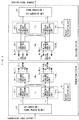
- FIG. 2 is a diagram illustrating a configuration of Example 1 of the OAM multiplexing communication system of the present invention.
- a transmitting station includes an S/P conversion/signal processing unit 11, L transmitting weight multiplication units such as a first transmitting weight multiplication unit 13-1 to an L-th transmitting weight multiplication unit 13-L, M TX transmitting OAM mode generation units such as a first transmitting OAM mode generation unit 14-1 to an M TX -th transmitting OAM mode generation unit 14-M TX respectively corresponding to M TX transmitting UCAs 15-1 to 15-M TX , and a reference signal transmission unit 16.
- L transmitting weight multiplication units such as a first transmitting weight multiplication unit 13-1 to an L-th transmitting weight multiplication unit 13-L
- M TX transmitting OAM mode generation units such as a first transmitting OAM mode generation unit 14-1 to an M TX -th transmitting OAM mode generation unit 14-M TX respectively corresponding to M TX transmitting UCAs 15-1 to
- a receiving station includes M RX receiving OAM mode demultiplex units such as a first receiving OAM mode demultiplex unit 22-1 to an M RX -th receiving OAM mode demultiplex unit 22-M RX respectively corresponding to M RX receiving UCAs 21-1 to 21-M RX , L receiving weight multiplication units such as a first receiving weight multiplication unit 23-1 to an L-th receiving weight multiplication unit 23-L, a signal processing/P/S conversion unit 24, a channel state acquisition unit 26, a weight calculation unit 27, and a feedback unit 28.
- M RX receiving OAM mode demultiplex units such as a first receiving OAM mode demultiplex unit 22-1 to an M RX -th receiving OAM mode demultiplex unit 22-M RX respectively corresponding to M RX receiving UCAs 21-1 to 21-M RX
- L receiving weight multiplication units such as a first receiving weight multiplication unit 23-1 to an L-th receiving weight multiplication unit 23-L
- a signal processing/P/S conversion unit 24, a channel state acquisition
- the OAM multiplexing communication system of Example 1 has an antenna configuration using an M-UCA unlike the configuration of the related art. There are differences in that a weight calculated by acquiring channel information is fed back to the transmitting station, and weights calculated based on the channel information are multiplied in the transmitting station and the receiving station.
- the l-th transmitting weight multiplication unit 13-I multiplies the transmission signal s l by a transmitting weight V l so as to output s' l .
- V l ⁇ C M TX ⁇ 1 s i ⁇ V l s l s i 1 , ... , s i M TX T
- D m Tx is a DFT matrix of N TX (m) ⁇ L of which a component corresponding to p row and q column is given by [Expression 5], j in the expression indicates an imaginary number unit, and l(q) indicates a discrete frequency index of DFT on the q-th column. exp ⁇ j 2 ⁇ p ⁇ 1 ⁇ l q N TX m
- a process related to the DFT calculation may be performed by an analog circuit using the same Butler matrix as in Non-Patent Document 1, and may be performed through digital signal processing.
- Output signals from the first transmitting OAM mode generation unit 14-1 to the M TX -th transmitting OAM mode generation unit 14-M TX are transmitted from the transmitting UCAs 15-1 to 15-M TX respectively coupled to DFT calculation units to the receiving UCAs.
- the k-th receiving OAM mode demultiplex unit 22-k of the receiving station multiplies the signal received by the k-th receiving UCA 21-k by an IDFT matrix D k RX , and outputs a result thereof.
- a component corresponding to p row and q column of the IDFT matrix D k RX is expressed as follows. D k RX ⁇ C L ⁇ N RX k
- l(p) indicates a discrete frequency index of IDFT on a p-th column.
- U l ⁇ C 1 ⁇ M RX r l U l l l
- the signal processing/P/S conversion unit 24 estimates a transmitted information bit string based on the signal r l subjected to receiving weight multiplication, performs P/S conversion on the estimated information bit string, and arranges the information bit strings in an original order.
- the reference signal transmission unit 16 of the transmitting station transmits a known signal sequence for estimating a channel response to the receiving station.
- the channel state acquisition unit 26 of the receiving station is coupled to the first receiving OAM mode demultiplex unit 22-1 to the M RX -th receiving OAM mode demultiplex unit 22-M RX , and estimates a channel response based on the known signal sequence.
- the estimated information is output to the weight calculation unit 27.
- the weight calculation unit 27 determines a transmitting weight and a receiving weight based on an estimated value in the channel state acquisition unit 26, sets the weights in the first receiving weight multiplication unit 23-1 to the L-th receiving weight multiplication unit 23-L of the receiving station, and sets the weights in the first transmitting weight multiplication unit 13-1 to the L-th transmitting weight multiplication unit 13-L of the transmitting station via the feedback unit 28.
- an interference component remaining in the signal r l subjected to receiving weight multiplication is expressed by an equation.
- Equation (5) is an interference component, and signal quality deteriorates due to interference from transmission signals having different indexes I.
- ⁇ l , k is a matrix of M RX ⁇ M TX representing interference from the OAM mode k to the OAM mode I.
- Example 1 a matrix of an interference component is subjected to singular value decomposition (SVD), and a vector orthogonal to a left singular vector with a large interference amount is used as a receiving weight, and thus the interference component is suppressed.
- SVD singular value decomposition
- ⁇ l INT ⁇ l , 1 , ... , ⁇ l , m ⁇ C M TX L
- Each of the matrixes ( u l ,1 , ... , u l,M RX ) and ( v l ,1 , ..., v l , M TX ( L -1) ) is a unitary matrix.
- O n ⁇ m indicates a zero matrix of n rows and m columns.
- the singular value ⁇ m is assumed to be
- Equation (5) may be rewritten as follows by using the singular value decomposition result in Equation (6).
- Equation (7) It can be seen from Equation (7) that, if the received signal r l is multiplied by the complex conjugate transposition u H l,m of the left singular vector u l,m , components other than ⁇ m u l,m v H l,m are removed from the interference component (the second term in Equation (7)) included in an output from the l-th receiving weight multiplication unit 23-1 due to the orthogonality between left singular vectors.
- the left singular vector u H l,MRX in which a singular value is the minimum may be used as the receiving weight U l such that a great interference term is removed.
- the received signal r l is given as follows, and it can be seen that the interference component is suppressed after receiving weight multiplication.
- a receiving weight may be a vector other than the left singular vector u H l,MRX with the minimum singular value, for example, may be u H l,MRX-1 .
- the matrix u H l , MRX ⁇ l forms an eigenspace not including a main interference component in a received signal.
- the eigenspace when a signal is transmitted by using an eigenvector having nonzero eigenvalues as a transmitting weight, it is possible to realize transmission of a signal not including a main interference component.
- a right singular vector having nonzero singular values is determined as the transmitting weight V l.
- ⁇ l , 1 ⁇ C 1 ⁇ 1 is a left singular vector of u l , M RX H ⁇ l
- ⁇ l , m ⁇ C M TX ⁇ 1 is a right singular vector of u l , M RX H ⁇ l
- ⁇ l ,1 is an eigenvalue
- Equation (8) When the right singular vector ⁇ l ,1 in Equation (8) is determined as the transmission vector V l , the following equation is given.
- a receiving weight is not u H l,MRX
- a transmitting weight is determined based on a singular value decomposition result of the multiplication result U l ⁇ l,m between the receiving weight U l and the matrix ⁇ l,m.
- FIG. 3 illustrates process procedures in Example 1 of the OAM multiplexing communication system of the present invention.
- the S/P conversion/signal processing unit 11 if a transmission signal sequence is input to the transmitting station, the S/P conversion/signal processing unit 11 generates a modulated signal (S11).
- the reference signal transmission unit 16 of the transmitting station transmits a known signal sequence (S12).
- the channel state acquisition unit 26 estimates responses ⁇ l and ⁇ l,k for each channel based on the known signal sequence (S21).
- the weight calculation unit 27 performs singular value decomposition represented in Equations (5) and (8) based on the estimated responses ⁇ l and ⁇ l,k for the channel, determines the transmitting weight V l and the receiving weight U l (S22), and sets the receiving weight U l in each receiving weight multiplication unit 23 of the receiving station.
- the feedback unit 28 sets the transmitting weight V l determined by the weight calculation unit 27 in each transmitting weight multiplication unit 13 of the transmitting station (S23).
- each transmitting weight multiplication unit 13 of the transmitting station multiplies the modulated signal generated in step S11 by the transmitting weight V l (S13).
- the transmitting OAM mode generation unit 14 performs an OAM mode generation process on the modulated signal multiplied by the transmitting weight V l according to DFT calculation (S14), and signals in respective OAM modes are respectively transmitted from the transmitting UCAs 15 of the transmitting station (S15).
- the respective receiving UCAs 21 of the receiving station receive the signals transmitted from the transmitting station (S24), and the receiving OAM mode demultiplex units 22 perform an OAM mode demultiplex process on the signals according to IDFT calculation (S25).
- each receiving weight multiplication unit 23 multiplies the received signals in the respective OAM modes by the receiving weight U l (S26).
- the signal processing/P/S conversion unit 24 demodulates the received signals in which inter-mode interference is suppressed through the above processes, to be converted into bit strings, and arranges the bit strings into an original information bit string through P/S conversion, and outputs the information bit string (S27).
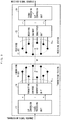
- FIG. 4 illustrates a modified configuration of Example 1 of the OAM multiplexing communication system of the present invention.
- a transmitting station includes an S/P conversion/signal processing unit 11, L transmitting weight multiplication units such as a first transmitting weight multiplication unit 13-1 to an L-th transmitting weight multiplication unit 13-L, M TX transmitting OAM mode generation units such as a first transmitting OAM mode generation unit 14-1 to an M TX -th transmitting OAM mode generation unit 14-M TX respectively corresponding to M TX transmitting UCAs 15-1 to 15-M TX , and a weight calculation unit 17.
- L transmitting weight multiplication units such as a first transmitting weight multiplication unit 13-1 to an L-th transmitting weight multiplication unit 13-L
- M TX transmitting OAM mode generation units such as a first transmitting OAM mode generation unit 14-1 to an M TX -th transmitting OAM mode generation unit 14-M TX respectively corresponding to M TX transmitting UCAs 15-1 to 15-M T
- a receiving station includes M RX receiving OAM mode demultiplex units such as a first receiving OAM mode demultiplex unit 22-1 to an M RX -th receiving OAM mode demultiplex unit 22-M RX respectively corresponding to M RX receiving UCAs 21-1 to 21-M RX , L receiving weight multiplication units such as a first receiving weight multiplication unit 23-1 to an L-th receiving weight multiplication unit 23-L, a signal processing/P/S conversion unit 24, and a weight calculation unit 29.
- M RX receiving OAM mode demultiplex units such as a first receiving OAM mode demultiplex unit 22-1 to an M RX -th receiving OAM mode demultiplex unit 22-M RX respectively corresponding to M RX receiving UCAs 21-1 to 21-M RX
- L receiving weight multiplication units such as a first receiving weight multiplication unit 23-1 to an L-th receiving weight multiplication unit 23-L
- a signal processing/P/S conversion unit 24 and a weight calculation unit 29.
- Example 1 illustrated in FIG. 2 A difference from Example 1 illustrated in FIG. 2 is that the receiving station does not perform channel estimation, and the transmitting station and the receiving station separately determine a transmitting weight and a receiving weight.
- a channel response is estimated in advance in the transmitting station and the receiving station, an estimated value is held in the weight calculation unit 17 of the transmitting station and the weight calculation unit 29 of the receiving station, the weight calculation units 17 and 29 determine a transmitting weight and a receiving weight based on the channel response, and set the weights in the transmitting weight multiplication unit 13 and the receiving weight multiplication unit 23.
- FIG. 5 illustrates process procedures in the modified configuration of Example 1 of the OAM multiplexing communication system of the present invention.
- the weight calculation unit 17 determines the transmitting weight V l based on a channel response value held in advance, and sets the transmitting weight in each transmitting weight multiplication unit 13 (S31).
- the S/P conversion/signal processing unit 11 generates a modulated signal (S32).
- each transmitting weight multiplication unit 13 multiplies the generated modulated signal by the transmitting weight V l (S33).
- the transmitting OAM mode generation unit 14 performs an OAM mode generation process on the modulated signal multiplied by the transmitting weight V l according to DFT calculation (S34), and signals in respective OAM modes are respectively transmitted from the transmitting UCAs 15 (S35).
- the weight calculation unit 29 determines the receiving weight U l based on a channel response value held in advance, and sets the receiving weight in each receiving weight multiplication unit 23 (S41).
- the respective receiving UCAs 21 receive the signals transmitted from the transmitting station
- each receiving weight multiplication unit 23 multiplies the received signals in the respective OAM modes by the receiving weight U l (S44).
- the signal processing/P/S conversion unit 24 demodulates the received signals in which inter-mode interference is suppressed through the above processes, to be converted into bit strings, and arranges the bit strings into an original information bit string through P/S conversion, and outputs the information bit string (S45).
- FIG. 6 is a diagram illustrating a configuration of Example 2 of the OAM multiplexing communication system of the present invention.
- a transmitting station includes an S/P conversion/signal processing unit 12, L transmitting weight multiplication units such as a first transmitting weight multiplication unit 13-1 to an L-th transmitting weight multiplication unit 13-L respectively receiving M 1 to M L signals, M TX transmitting OAM mode generation units such as a first transmitting OAM mode generation unit 14-1 to an M TX -th transmitting OAM mode generation unit 14-M TX respectively corresponding to M TX transmitting UCAs 15-1 to 15-M TX , and a reference signal transmission unit 16.
- L transmitting weight multiplication units such as a first transmitting weight multiplication unit 13-1 to an L-th transmitting weight multiplication unit 13-L respectively receiving M 1 to M L signals
- M TX transmitting OAM mode generation units such as a first transmitting OAM mode generation unit 14-1 to an M TX -th transmitting OAM mode generation unit 14-M T
- a receiving station includes M RX receiving OAM mode demultiplex units such as a first receiving OAM mode demultiplex unit 22-1 to an M RX -th receiving OAM mode demultiplex unit 22-M RX respectively corresponding to M RX receiving UCAs 21-1 to 21-M RX , L receiving weight multiplication units such as a first receiving weight multiplication unit 23-1 to an L-th receiving weight multiplication unit 23-L, a signal processing/P/S conversion unit 25 receiving M 1 to M L received signals, a channel state acquisition unit 26, a weight calculation unit 27, and a feedback unit 28.
- M RX receiving OAM mode demultiplex units such as a first receiving OAM mode demultiplex unit 22-1 to an M RX -th receiving OAM mode demultiplex unit 22-M RX respectively corresponding to M RX receiving UCAs 21-1 to 21-M RX
- L receiving weight multiplication units such as a first receiving weight multiplication unit 23-1 to an L-th receiving weight multiplication unit 23-L
- the OAM multiplexing communication system of Example 2 is different from the OAM multiplexing communication system of Example 1 in that a modulated signal that is input to the single transmitting weight multiplication unit 13 has a plurality of systems, and a received signal that is output from the single receiving weight multiplication unit 23 has a plurality of systems. Since the number of input systems is increased, matrix sizes of a transmitting weight and a receiving weight differ, and processing methods in the transmitting weight multiplication unit 13 and the receiving weight multiplication unit 23 differ.
- Example 1 there is a difference from Example 1 in that, among OAM modes, an OAM mode having a high signal-to-interference-plus-noise ratio (SINR) is selected and used, a throughput is improved while compensating for interference due to a tilt, axis deviation, or multipaths.
- SINR signal-to-interference-plus-noise ratio
- the l-th transmitting weight multiplication unit 13-1 receives M l parallel modulated signals s l , and outputs modulated signals s' l obtained by multiplying the respective modulated signals by the transmitting weight V l .
- the l-th receiving weight multiplication unit 23-1 receives outputs (r l [l],...,r MRX [l]) T from the first receiving OAM mode demultiplex unit 22-1 to the M RX -th receiving OAM mode demultiplex unit 22-M RX , and outputs received signals r l obtained by multiplying the outputs by the receiving weight U l .
- U l ⁇ C M l ⁇ M RX r l ⁇ r l , 1 , ... , r l , M l T U l r 1 l , ... , r M RX l T
- the received signal vector r l U l ⁇ l V l s l + U l ⁇ k ⁇ l ⁇ l , k V k s k
- Equation (9) is an interference component.
- Equation (9) may be rewritten as follows by using the singular value decomposition result in Equation (6).
- the left singular vector (u H l,MRX-(Ml-1) ,...,u H l,MRX-1 ,u H l,MRX ) is multiplied by a vector (r' l [l],...,r' MRX [l]) T in which l-th sequences output from the first receiving OAM mode demultiplex unit 22-1 to the M RX -th receiving OAM mode demultiplex unit 22-M RX are arranged, and thus some interference components are eliminated.
- a transmitting weight and a receiving weight are determined by using a singular vector obtained by subjecting the matrix (u H l,MRX-(Ml-1) ,...,u H l,MRX-1 ,u H l ,MRX ) ⁇ l of the main signal component to singular value decomposition. Consequently, eigenmode transmission can be performed while reducing inter-mode interference.
- a singular value decomposition result of the identical matrix is as follows. [Math.
- ⁇ l (img) and ⁇ l (ker) are respectively a left singular vector corresponding to nonzero singular values of (u H l,MRX-(Ml-1) ,...,u H l,MRX-1 ,u H l,MRX ) ⁇ l and a left singular vector corresponding to zero singular values thereof
- ⁇ l (img) and ⁇ l (ker) are respectively a right singular vector corresponding to nonzero singular values of the identical matrix and a right singular vector corresponding to zero singular values thereof.
- the transmitting weight V l and the receiving weight U l are determined as in Equation (11) based on the singular value decomposition result represented in Equation (10). [Math.
- V l ⁇ l img
- U l ⁇ l img H u l , M RX ⁇ M l ⁇ 1 H , ... , u l , M RX ⁇ 1 H , u l , M RX H
- the received signal r l is output as a signal in which interference is suppressed as follows.
- the multiplex number M l may be determined based on a selection standard depending on a total capacity computed according to an SINR or the like, and may be determined based on other selection standards. Alternatively, the multiplex number M l may be a fixed value determined in advance by a system.
- FIG. 7 illustrates process procedures in Example 2 of the OAM multiplexing communication system of the present invention.
- the reference signal transmission unit 16 of the transmitting station transmits a known signal sequence (S51).
- the channel state acquisition unit 26 estimates responses ⁇ l and ⁇ l,k for each channel based on the known signal sequence (S61).
- the weight calculation unit 27 performs singular value decomposition represented in Equation (9) based on the estimated responses ⁇ l and ⁇ l,k for the channel, determines the transmitting weight V l and the receiving weight U l as in Equation (10) and also determines the multiplex number M l , and sets the receiving weight U l in each receiving weight multiplication unit 23 (S62).
- the multiplex number M l may be a value set in advance, and may be an adaptively selected value.
- the feedback unit 28 sets the multiplex number M l determined by the weight calculation unit 27 in the S/P conversion/signal processing unit 12 of the transmitting station, and sets the transmitting weight V l in each transmitting weight multiplication unit 13 of the transmitting station (S63).
- the S/P conversion/signal processing unit 12 in which the multiplex number M l is set generates a modulated signal (S52).
- each transmitting weight multiplication unit 13 multiplies the generated modulated signal by the transmitting weight V l (S53).
- the transmitting OAM mode generation unit 14 performs an OAM mode generation process on the modulated signal multiplied by the transmitting weight V l according to DFT calculation (S54), and signals in respective OAM modes are respectively transmitted from the transmitting UCAs 15 of the transmitting station (S55).
- the respective receiving UCAs 21 of the receiving station receive the signals transmitted from the transmitting station (S64), and the receiving OAM mode demultiplex units 22 perform an OAM mode demultiplex process on the signals according to IDFT calculation (S65).
- each receiving weight multiplication unit 23 multiplies the received signals in the respective OAM modes by the receiving weight U l (S66).
- the signal processing/P/S conversion unit 25 demodulates the received signals in which inter-mode interference is suppressed through the above processes, to be converted into bit strings, and arranges the bit strings into an original information bit string through P/S conversion, and outputs the information bit string (S67).
- FIG. 8 illustrates a modified configuration of Example 2 of the OAM multiplexing communication system of the present invention.
- a transmitting station includes an S/P conversion/signal processing unit 12, L transmitting weight multiplication units such as a first transmitting weight multiplication unit 13-1 to an L-th transmitting weight multiplication unit 13-L, M TX transmitting OAM mode generation units such as a first transmitting OAM mode generation unit 14-1 to an M TX -th transmitting OAM mode generation unit 14-M TX respectively corresponding to M TX transmitting UCAs 15-1 to 15-M TX , and a weight calculation unit 17.
- L transmitting weight multiplication units such as a first transmitting weight multiplication unit 13-1 to an L-th transmitting weight multiplication unit 13-L
- M TX transmitting OAM mode generation units such as a first transmitting OAM mode generation unit 14-1 to an M TX -th transmitting OAM mode generation unit 14-M TX respectively corresponding to M TX transmitting UCAs 15-1 to 15-M T
- a receiving station includes M RX receiving OAM mode demultiplex units such as a first receiving OAM mode demultiplex unit 22-1 to an M RX -th receiving OAM mode demultiplex unit 22-M RX respectively corresponding to M RX receiving UCAs 21-1 to 21-M RX , L receiving weight multiplication units such as a first receiving weight multiplication unit 23-1 to an L-th receiving weight multiplication unit 23-L, a signal processing/P/S conversion unit 25 receiving M 1 to M L received signals, and a weight calculation unit 29.
- M RX receiving OAM mode demultiplex units such as a first receiving OAM mode demultiplex unit 22-1 to an M RX -th receiving OAM mode demultiplex unit 22-M RX respectively corresponding to M RX receiving UCAs 21-1 to 21-M RX
- L receiving weight multiplication units such as a first receiving weight multiplication unit 23-1 to an L-th receiving weight multiplication unit 23-L
- a signal processing/P/S conversion unit 25 receiving M 1 to M L received signals
- Example 2 illustrated in FIG. 6 A difference from Example 2 illustrated in FIG. 6 is that the receiving station does not perform channel estimation, and the transmitting station and the receiving station separately determine a transmitting weight and a receiving weight.
- a channel response is estimated in advance in the transmitting station and the receiving station, an estimated value is held in the weight calculation unit 17 of the transmitting station and the weight calculation unit 29 of the receiving station, the weight calculation units 17 and 29 determine a transmitting weight and a receiving weight based on the channel response, and set the weights in the transmitting weight multiplication unit 13 and the receiving weight multiplication unit 23.
- the multiplex number M l is determined in advance, and the transmitting station and the receiving station have the information regarding the multiplex number M l together, and can thus perform communication without performing a feedback process.
- Process procedures in the modified configuration of Example 2 of the OAM multiplexing communication system of the present invention are the same as the process procedures in the modified configuration of Example 1 illustrated in FIG. 5 except that the S/P conversion/signal processing unit 12 of the transmitting station generates modulated signals corresponding to the multiplex number M l , and the signal processing/P/S conversion unit 25 of the receiving station demodulates received signals corresponding to the multiplex number M l .
Landscapes
- Engineering & Computer Science (AREA)
- Signal Processing (AREA)
- Computer Networks & Wireless Communication (AREA)
- Power Engineering (AREA)
- Physics & Mathematics (AREA)
- Mathematical Physics (AREA)
- Radio Transmission System (AREA)
Abstract
Description
- The present invention relates to an OAM multiplexing communication system and an inter-mode interference elimination method of subjecting a radio signal to spatial multiplex transmission by using orbital angular momentum (OAM) of an electromagnetic wave.
- A technique of subjecting a radio signal to spatial multiplex transmission using OAM is effective to improve a transmission capacity in wireless communication. An electric wave having an OAM mode has a feature that an equiphase surface thereof is distributed in a spiral form along a rational direction centering on a propagation axis of a beam, and a mode in which a cycle of a spiral formed by an equiphase surface is 2π×k will be referred to as an OAM mode k. Different OAM modes have orthogonality in a rotational direction, and thus signals in a plurality of OAM modes can be subjected to spatial multiplex transmission. For example, since signals in an
OAM mode 1 and an OAM mode 2 are orthogonal to each other on a space, even though the signals in the modes are simultaneously transmitted from transmitting antennae, the signals in theOAM mode 1 and the OAM mode 2 can be demultiplexed from each other on a reception side. As a method of generating an OAM mode, a method using a uniform circular array (UCA) in which a plurality of antenna elements are disposed circularly at an equal interval has been reported. - In an OAM multiplexing communication system, UCAs used as transmitting and receiving antennae are disposed to face each other, and weight multiplication on a transmission side and weight multiplication on a reception side related to OAM mode transmission can be uniformized regardless of a distance between the transmitting and receiving antennae (Non-Patent Document 1). Herein, a Butler matrix circuit performing a discrete Fourier transform (DFT) applied to transmitting and receiving weight multiplication is mounted, and a calculation amount for digital signal processing related to OAM mode transmission is reduced.
-
FIG. 9 illustrates a configuration example of an OAM multiplexing communication system of the related art. InFIG. 9 , each of antennae of a transmitting station and a receiving station is a UCA including L antenna elements. For simplification of description, the number of antenna elements of the UCA of each of the transmitting station and the receiving station is the same as a spatial multiplex number (L multiplex). - When a transmission signal sequentially is input, a serial (S)/parallel (P) conversion/
signal processing unit 11 of the transmitting station converts the transmission signal sequence into L parallel bit strings, performs modulation on each bit string, and outputs a transmission signal sequence sl (where I = 1, 2, ..., and L). A transmitting OAMmode generation unit 14 receives the transmission signal sequence sl, performs DFT calculation, and outputs a result thereof to each antenna element of a transmittingUCA 15. The transmittingUCA 15 transmits an output signal from the transmitting OAMmode generation unit 14. - A receiving
UCA 21 of the receiving station receives a signal in a spatially multiplexed OAM mode with each antenna element, and outputs the signal to a receiving OAMmode demultiplex unit 22. The receiving OAMmode demultiplex unit 22 performs inverse DFT (IDFT) on a received signal in each antenna element, separates the spatially multiplexed OAM mode, and outputs a received signal sequence rl (where I = 1, 2, ..., and L). A signal processing/P/S conversion unit 24 demodulates each received signal sequence, and thus outputs received signal sequences rearranged in an original order. -
FIG. 9 schematically illustrates a positional relationship between the transmitting UCA 15 and the receiving UCA 21. Circularly disposed antenna elements (indicated by • inFIG. 9 ) forming the transmittingUCA 15 and thereceiving UCA 21 are disposed such that each antenna aperture surface is perpendicular to a straight line (optical axis) W connecting the centers P and Q of the antenna elements. In this case, a channel matrix H between the transmittingUCA 15 and thereceiving UCA 21 is a circulant matrix regardless of a distance between the transmitting and receiving UCAs. According to property of the circulant matrix, a channel matrix is subjected to eigenvalue decomposition through DFT calculation and IDFT calculation, and thus the received signal rl in the OAM multiplexing communication system illustrated inFIG. 9 is as follows at all times.
[Math. 1]
- Therefore, a signal can be received without interference between modes regardless of a transmission distance. Here, λl is a singular value in the mode I.
- Non-Patent Document 1: E. Sasaki, M. Hirabe, T. Maru, N. Zein, "Pragmatic OAM with Polarization Multiplexing Transmission for future 5G Ultra-High Capacity Radio", in Proceedings of EuMA2016, Oct. 2016.
- In the configuration disclosed in
Non-Patent Document 1, a transmitting UCA and a receiving UCA are disposed at positions facing each other, and the configuration is restricted to an open environment in which there is no reflected wave. However, in an actual operation, it is necessary to take into consideration a case where the transmitting UCA and the receiving UCA are provided at fixed positions deviated from front facing disposition, or the influence of a reflected wave or the like due to a surrounding environment. When a channel matrix between the transmitting UCA and the receiving UCA is deviated from ideal front facing disposition due to the influence, interference between OAM modes remains in an output stage of a Butler matrix circuit of a reception side. Thus, the received signal rl in the OAM mode I is represented in the following equation.
[Math. 2]
- Consequently, communication quality deteriorates due to interference from an OAM mode, indicated in the second term, which is different from the OAM mode I. In Equation (2), λ'l is a constant multiplied by an output in the OAM mode I, and λ'l,k is a constant indicating an interference amount from the OAM mode k to the OAM mode I.
- A proposition of the present invention is to provide an OAM multiplexing communication system and an inter-mode interference elimination method capable of suppressing inter-mode interference occurring due to deviation of an optical axis, a tilt, or a reflected wave between a transmitting UCA and a receiving UCA with low computational complexity.
- According to a first embodiment, there is provided an OAM multiplexing communication system that subjects a plurality of transmission signal sequences to spatial multiplex transmission by using an orbital angular momentum (OAM) mode, the OAM multiplexing communication system including a transmitting station including a transmitting antenna using an M-UCA formed of a plurality of MTX uniform circular arrays (UCAs) that are concentrically disposed at an equal interval and have different diameters, each of the UCAs having a plurality of antenna elements disposed circularly at an equal interval; and a receiving station including a receiving antenna using an M-UCA formed of a plurality of MRX UCAs in the same manner as the transmitting station, in which the transmitting station includes a plurality of transmitting weight multiplication units each inputting the plurality of transmission signal sequences and multiplying each of the transmission signal sequences by a transmitting weight, to be converted into MTX signals corresponding to the UCAs forming the M-UCA so as to output the converted signals, and MTX transmitting OAM mode generation units inputting the signals corresponding to the UCAs output from each of the plurality of transmitting weight multiplication units and performing discrete Fourier transform on the input signals, so as to output to the corresponding UCAs; and the receiving station includes MRX receiving OAM mode demultiplex units inputting signals from each of the UCAs forming the M-UCA and performing inverse Fourier transform on the input signals, so as to output by each of received signal sequences, and a plurality of receiving weight multiplication units multiplying for each of the received signal sequences output from the receiving OAM mode demultiplex units by a receiving weight, so as to demultiplex the received signal sequences subjected to spatial multiplex transmission and to output the received signal sequence in which interference between spatially multiplexed OAM modes is suppressed.
- In the OAM multiplexing communication system according to the first embodiment, the transmitting weight multiplication units are configured to receive the plurality of transmission signal sequences and to multiply the transmission signal sequences by the transmitting weight; and the receiving weight multiplication units are configured to demultiplex the plurality of received signal sequences subjected to the spatial multiplex transmission.
- The OAM multiplexing communication system according to the first embodiment further includes a weight calculation unit performing channel estimation based on output values from the receiving OAM mode demultiplex units for a known signal sequence transmitted from the transmitting station to the receiving station, and determining the transmitting weight and the receiving weight, in which the receiving weight is configured to set in the receiving weight multiplication units, and the transmitting weight is configured to feed back to the transmitting station from the receiving station to be set in the transmitting weight multiplication units, so that an interference component between OAM modes subjected to the spatial multiplex transmission is suppressed.
- According to a second embodiment, there is provided an inter-mode interference elimination method for an OAM multiplexing communication system that subjects a plurality of transmission signal sequences to spatial multiplex transmission by using an orbital angular momentum (OAM) mode; that includes a transmitting station including a transmitting antenna using an M-UCA formed of a plurality of MTX uniform circular arrays (UCAs) that are concentrically disposed at an equal interval and have different diameters, each of the UCAs having a plurality of antenna elements disposed circularly at an equal interval; and that includes a receiving station including a receiving antenna using an M-UCA formed of a plurality of MRX UCAs in the same manner as the transmitting station, the inter-mode interference elimination method including causing a plurality of transmitting weight multiplication units of the transmitting station each to input the plurality of transmission signal sequences and to multiply each of the transmission signal sequences by a transmitting weight, to be converted into MTX signals corresponding to the UCAs forming the M-UCA so as to output the converted signals; causing MTX transmitting OAM mode generation units of the transmitting station to input the signals corresponding to the UCAs output from each of the plurality of transmitting weight multiplication units and to perform discrete Fourier transform on the input signals, so as to output to the corresponding UCAs; causing MRX receiving OAM mode demultiplex units of the receiving station to input signals from each of the UCAs forming the M-UCA and to perform inverse Fourier transform on the input signals, so as to output by each of received signal sequences; and causing a plurality of receiving weight multiplication units of the receiving station to multiply for each of the received signal sequences output from the receiving OAM mode demultiplex units by a receiving weight so as to demultiplex the received signal sequence subjected to spatial multiplex transmission and to output the received signal sequence in which interference between spatially multiplexed OAM modes is suppressed.
- In the inter-mode interference elimination method for an OAM multiplexing communication system according to the second embodiment, in which channel estimation is performed based on output values from the receiving OAM mode demultiplex units for a known signal sequence transmitted from the transmitting station to the receiving station, and the transmitting weight and the receiving weight are determined; and the receiving weight is set in the receiving weight multiplication units, and the transmitting weight is fed back to the transmitting station from the receiving station to be set in the transmitting weight multiplication units, so that an interference component between OAM modes subjected to spatial multiplex transmission is suppressed.
- In the inter-mode interference elimination method for an OAM multiplexing communication system according to the second embodiment, in which the transmitting weight and the receiving weight for suppressing interference between spatially multiplexed signals may be determined based on a result of singular value decomposition on a matrix representing interference components from other discrete frequency components remaining in a specific discrete frequency component, and a result of singular value decomposition on a matrix representing a self-discrete frequency component, in outputs from the receiving OAM mode demultiplex units.
- A weight including a vector orthogonal to one or more vectors among vectors included in left singular vectors may be set as the receiving weight, the left singular vectors are a result of singular value decomposition on a matrix representing interference components from other discrete frequency components in outputs from the receiving OAM mode demultiplex units.
- The transmitting weight and the receiving weight may be determined based on singular value decomposition on a multiplication result between a vector orthogonal to a vector included in left singular vectors and a matrix representing a self-discrete frequency component, the left singular vectors are a result of singular value decomposition on a matrix representing interference components from other discrete frequency components in outputs from the receiving OAM mode demultiplex units.
- A multiplex number of spatially multiplexed signals may be determined based on a standard in which a total rate corresponding to a received signal quality is the maximum, or may be determined in advance.
- According to the present invention, a transmitting weight and a receiving weight are appropriately set, and thus it is possible to suppress interference between OAM modes caused by a case where a transmitting antenna and a receiving antenna are provided at fixed positions deviated from front facing disposition, or a reflected wave or the like due to a surrounding environment.
-
-
FIG. 1 is a diagram illustrating a configuration example of an M-UCA of an OAM multiplexing communication system of the present invention. -
FIG. 2 is a diagram illustrating a configuration of Example 1 of the OAM multiplexing communication system of the present invention. -
FIG. 3 is a flowchart illustrating process procedures in Example 1 of the OAM multiplexing communication system of the present invention. -
FIG. 4 is a diagram illustrating a modified configuration of Example 1 of the OAM multiplexing communication system of the present invention. -
FIG. 5 is a flowchart illustrating process procedures in the modified configuration of Example 1 of the OAM multiplexing communication system of the present invention. -
FIG. 6 is a diagram illustrating a configuration of Example 2 of the OAM multiplexing communication system of the present invention. -
FIG. 7 is a flowchart illustrating process procedures in Example 2 of the OAM multiplexing communication system of the present invention. -
FIG. 8 is a diagram illustrating a modified configuration of Example 2 of the OAM multiplexing communication system of the present invention. -
FIG. 9 is a diagram illustrating a configuration example of an OAM multiplexing communication system of the related art. -
FIG. 1 is a diagram illustrating a configuration example of an M-UCA of an OAM multiplexing communication system of the present invention. InFIG. 1 , a multi (M)-UCA has a configuration in which a plurality of UCAs are disposed concentrically or at an equal interval. Herein, a configuration in which four UCAs are disposed is illustrated, and the UCAs are referred to as a first UCA, a second UCA, a third UCA, and a fourth UCA in this order from the inner UCAs. A transmitting UCA will be referred to as an n-th transmitting UCA, and a receiving UCA will be referred to as an n-th receiving UCA. As an example, each UCA includes eight antenna elements (indicated by • inFIG. 1 ), but the number of antenna elements of each UCA is not necessarily required to be the same. - The definition of each symbol used in the following description is as follows.

-
FIG. 2 is a diagram illustrating a configuration of Example 1 of the OAM multiplexing communication system of the present invention. InFIG. 2 , a transmitting station includes an S/P conversion/signal processing unit 11, L transmitting weight multiplication units such as a first transmitting weight multiplication unit 13-1 to an L-th transmitting weight multiplication unit 13-L, MTX transmitting OAM mode generation units such as a first transmitting OAM mode generation unit 14-1 to an MTX-th transmitting OAM mode generation unit 14-MTX respectively corresponding to MTX transmitting UCAs 15-1 to 15-MTX, and a referencesignal transmission unit 16. - A receiving station includes MRX receiving OAM mode demultiplex units such as a first receiving OAM mode demultiplex unit 22-1 to an MRX-th receiving OAM mode demultiplex unit 22-MRX respectively corresponding to MRX receiving UCAs 21-1 to 21-MRX, L receiving weight multiplication units such as a first receiving weight multiplication unit 23-1 to an L-th receiving weight multiplication unit 23-L, a signal processing/P/
S conversion unit 24, a channelstate acquisition unit 26, aweight calculation unit 27, and afeedback unit 28. - The OAM multiplexing communication system of Example 1 has an antenna configuration using an M-UCA unlike the configuration of the related art. There are differences in that a weight calculated by acquiring channel information is fed back to the transmitting station, and weights calculated based on the channel information are multiplied in the transmitting station and the receiving station.
- First, input and output relationships of the transmitting station and the receiving station in Example 1 are expressed by equations. The transmitting station performs S/P conversion on an input transmission signal sequence that is thus converted into L parallel bit strings, and modulates each bit string so as to generate a transmission signal sl (where I = 1, 2, ..., and L)
- The l-th transmitting weight multiplication unit 13-I multiplies the transmission signal sl by a transmitting weight Vl so as to output s'l.

- The m-th OAM mode generation unit 14-m receives a signal vector S'[m] = (s'1[m],...,s'L[m])T in which m-th signals s'l[m] (where I = 1, 2, ..., and L) respectively output from the first transmitting weight multiplication unit 13-1 to the L-th transmitting weight multiplication unit 13-L are arranged, and multiplies S'[m] by a DFT matrix Dm TX, and outputs a result thereof. Here, Dm Tx is a DFT matrix of NTX(m)×L of which a component corresponding to p row and q column is given by [Expression 5], j in the expression indicates an imaginary number unit, and l(q) indicates a discrete frequency index of DFT on the q-th column.

- A process related to the DFT calculation may be performed by an analog circuit using the same Butler matrix as in
Non-Patent Document 1, and may be performed through digital signal processing. Output signals from the first transmitting OAM mode generation unit 14-1 to the MTX-th transmitting OAM mode generation unit 14-MTX are transmitted from the transmitting UCAs 15-1 to 15-MTX respectively coupled to DFT calculation units to the receiving UCAs. In this case, a signal received by the k-th receiving UCA 21-k is as follows.
[Math. 6]
- In Expression (3), for simplification of description, a noise term is omitted.
- Next, the k-th receiving OAM mode demultiplex unit 22-k of the receiving station multiplies the signal received by the k-th receiving UCA 21-k by an IDFT matrix Dk RX, and outputs a result thereof. Here, a component corresponding to p row and q column of the IDFT matrix Dk RX is expressed as follows.

- Component corresponding to p row and q column:

- An output from the k-th reception IDFT calculation unit 22-k is as follows.

- The l-th receiving weight multiplication unit 23-1 receives the following vector r[l] in which l-th outputs rk[l] (where k = 1, 2, ..., and MRX) from the first receiving OAM mode demultiplex unit 22-1 to the MRX-th receiving OAM mode demultiplex unit 22-MRX are arranged, and multiplies the vector by a receiving weight Ul, and outputs a result thereof.


- The signal processing/P/
S conversion unit 24 estimates a transmitted information bit string based on the signal rl subjected to receiving weight multiplication, performs P/S conversion on the estimated information bit string, and arranges the information bit strings in an original order. - The reference
signal transmission unit 16 of the transmitting station transmits a known signal sequence for estimating a channel response to the receiving station. - The channel
state acquisition unit 26 of the receiving station is coupled to the first receiving OAM mode demultiplex unit 22-1 to the MRX-th receiving OAM mode demultiplex unit 22-MRX, and estimates a channel response based on the known signal sequence. The estimated information is output to theweight calculation unit 27. - The
weight calculation unit 27 determines a transmitting weight and a receiving weight based on an estimated value in the channelstate acquisition unit 26, sets the weights in the first receiving weight multiplication unit 23-1 to the L-th receiving weight multiplication unit 23-L of the receiving station, and sets the weights in the first transmitting weight multiplication unit 13-1 to the L-th transmitting weight multiplication unit 13-L of the transmitting station via thefeedback unit 28. - Next, a description will be made of a method of calculating a transmitting weight and a receiving weight in the
weight calculation unit 27. For clarification of description, an interference component remaining in the signal rl subjected to receiving weight multiplication is expressed by an equation. First, when the M-UCAs of the transmitting station and the receiving station face each other, and thus interference does not occur, the channel matrix Hm,k is made diagonal as a result of being multiplied by the IDFT matrix Dk RX from the left and multiplied by the DFT matrix Dm TX from the right. Therefore, the signal rl output from the l-th receiving weight multiplication unit 23-1 is as follows.
[Math. 9]
- Λl in Equation (4) is a matrix of MRX×MTX representing each channel response. It can be seen from Equation (4) that interference from other signals (different OAM modes) having different indexes l does not occur in front facing. Therefore, in the same manner as in the configuration of the related art, the signal processing/P/
S conversion unit 24 can estimate a bit string sl for each signal rl without interference from other modes. On the other hand, in other cases, the signal rl is a signal including interference from other modes.
[Math. 10]
- The second term in Equation (5) is an interference component, and signal quality deteriorates due to interference from transmission signals having different indexes I. Λl,k is a matrix of MRX×MTX representing interference from the OAM mode k to the OAM mode I.
- Hereinafter, a description will be made of a method of determining the transmitting weight Vl and the receiving weight Ul for improving communication quality by suppressing an interference component (a signal component of the second term in Equation (5)).
- In Example 1, a matrix of an interference component is subjected to singular value decomposition (SVD), and a vector orthogonal to a left singular vector with a large interference amount is used as a receiving weight, and thus the interference component is suppressed.
- First, if the matrix Λl (INT) of the interference component is subjected to singular value decomposition in order to find out a singular vector with a large interference amount, Equation (6) is obtained.
[Math. 11]
[Math. 12]
Here,is a left singular vector of

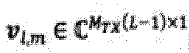

- Each of the matrixes (u l,1, ... , ul,M
RX ) and (v l,1, ..., v l,MTX (L-1)) is a unitary matrix. - O n×m indicates a zero matrix of n rows and m columns. The singular value σm is assumed to be |σ1| > |σ2| > ··· > |σ M
RX |. - The received signal in Equation (5) may be rewritten as follows by using the singular value decomposition result in Equation (6).
[Math. 13]
- It can be seen from Equation (7) that, if the received signal rl is multiplied by the complex conjugate transposition uH l,m of the left singular vector ul,m, components other than σmul,mvH l,m are removed from the interference component (the second term in Equation (7)) included in an output from the l-th receiving weight multiplication unit 23-1 due to the orthogonality between left singular vectors. In order to effectively suppress interference in a received signal, the left singular vector uH l,MRX in which a singular value is the minimum may be used as the receiving weight Ul such that a great interference term is removed. In this case, the received signal rl is given as follows, and it can be seen that the interference component is suppressed after receiving weight multiplication. A receiving weight may be a vector other than the left singular vector uH l,MRX with the minimum singular value, for example, may be uH l,MRX-1.

- On the other hand, the matrix uH l,MRXΛl forms an eigenspace not including a main interference component in a received signal. In the eigenspace, when a signal is transmitted by using an eigenvector having nonzero eigenvalues as a transmitting weight, it is possible to realize transmission of a signal not including a main interference component. Specifically, among right singular vectors obtained by subjecting the matrix uH l,MRXΛl to singular value decomposition, a right singular vector having nonzero singular values is determined as the transmitting weight Vl.
[Math. 15]
- Here,


- When the right singular vector Φ l,1 in Equation (8) is determined as the transmission vector V l, the following equation is given.

- Thus, interference occurring due to a tilt or a reflected wave is reduced, and thus it is possible to increase bit estimation accuracy in a demodulation unit. If a receiving weight is not uH l,MRX, a transmitting weight is determined based on a singular value decomposition result of the multiplication result UlΛl,m between the receiving weight Ul and the matrix Λl,m.
-
FIG. 3 illustrates process procedures in Example 1 of the OAM multiplexing communication system of the present invention. InFIG. 3 , if a transmission signal sequence is input to the transmitting station, the S/P conversion/signal processing unit 11 generates a modulated signal (S11). Next, the referencesignal transmission unit 16 of the transmitting station transmits a known signal sequence (S12). When the receiving station receives the known signal sequence, the channelstate acquisition unit 26 estimates responses Λl and Λl,k for each channel based on the known signal sequence (S21). Theweight calculation unit 27 performs singular value decomposition represented in Equations (5) and (8) based on the estimated responses Λl and Λl,k for the channel, determines the transmitting weight Vl and the receiving weight Ul (S22), and sets the receiving weight Ul in each receivingweight multiplication unit 23 of the receiving station. Thefeedback unit 28 sets the transmitting weight Vl determined by theweight calculation unit 27 in each transmittingweight multiplication unit 13 of the transmitting station (S23). - Next, each transmitting
weight multiplication unit 13 of the transmitting station multiplies the modulated signal generated in step S11 by the transmitting weight Vl (S13). The transmitting OAMmode generation unit 14 performs an OAM mode generation process on the modulated signal multiplied by the transmitting weight Vl according to DFT calculation (S14), and signals in respective OAM modes are respectively transmitted from the transmitting UCAs 15 of the transmitting station (S15). - The respective receiving UCAs 21 of the receiving station receive the signals transmitted from the transmitting station (S24), and the receiving OAM
mode demultiplex units 22 perform an OAM mode demultiplex process on the signals according to IDFT calculation (S25). Next, each receivingweight multiplication unit 23 multiplies the received signals in the respective OAM modes by the receiving weight Ul (S26). The signal processing/P/S conversion unit 24 demodulates the received signals in which inter-mode interference is suppressed through the above processes, to be converted into bit strings, and arranges the bit strings into an original information bit string through P/S conversion, and outputs the information bit string (S27). -
FIG. 4 illustrates a modified configuration of Example 1 of the OAM multiplexing communication system of the present invention. InFIG. 4 , a transmitting station includes an S/P conversion/signal processing unit 11, L transmitting weight multiplication units such as a first transmitting weight multiplication unit 13-1 to an L-th transmitting weight multiplication unit 13-L, MTX transmitting OAM mode generation units such as a first transmitting OAM mode generation unit 14-1 to an MTX-th transmitting OAM mode generation unit 14-MTX respectively corresponding to MTX transmitting UCAs 15-1 to 15-MTX, and aweight calculation unit 17. - A receiving station includes MRX receiving OAM mode demultiplex units such as a first receiving OAM mode demultiplex unit 22-1 to an MRX-th receiving OAM mode demultiplex unit 22-MRX respectively corresponding to MRX receiving UCAs 21-1 to 21-MRX, L receiving weight multiplication units such as a first receiving weight multiplication unit 23-1 to an L-th receiving weight multiplication unit 23-L, a signal processing/P/
S conversion unit 24, and aweight calculation unit 29. - A difference from Example 1 illustrated in
FIG. 2 is that the receiving station does not perform channel estimation, and the transmitting station and the receiving station separately determine a transmitting weight and a receiving weight. In other words, in the configuration illustrated inFIG. 4 , a channel response is estimated in advance in the transmitting station and the receiving station, an estimated value is held in theweight calculation unit 17 of the transmitting station and theweight calculation unit 29 of the receiving station, theweight calculation units weight multiplication unit 13 and the receivingweight multiplication unit 23. -
FIG. 5 illustrates process procedures in the modified configuration of Example 1 of the OAM multiplexing communication system of the present invention. InFIG. 5 , if a transmission signal sequence is input to the transmitting station, theweight calculation unit 17 determines the transmitting weight Vl based on a channel response value held in advance, and sets the transmitting weight in each transmitting weight multiplication unit 13 (S31). The S/P conversion/signal processing unit 11 generates a modulated signal (S32). Next, each transmittingweight multiplication unit 13 multiplies the generated modulated signal by the transmitting weight Vl (S33). The transmitting OAMmode generation unit 14 performs an OAM mode generation process on the modulated signal multiplied by the transmitting weight Vl according to DFT calculation (S34), and signals in respective OAM modes are respectively transmitted from the transmitting UCAs 15 (S35). - On the other hand, in the receiving station, the
weight calculation unit 29 determines the receiving weight Ul based on a channel response value held in advance, and sets the receiving weight in each receiving weight multiplication unit 23 (S41). The respective receiving UCAs 21 receive the signals transmitted from the transmitting station - (S42), and the receiving OAM
mode demultiplex units 22 perform an OAM mode demultiplex process on the signals according to IDFT calculation (S43). Next, each receivingweight multiplication unit 23 multiplies the received signals in the respective OAM modes by the receiving weight Ul (S44). The signal processing/P/S conversion unit 24 demodulates the received signals in which inter-mode interference is suppressed through the above processes, to be converted into bit strings, and arranges the bit strings into an original information bit string through P/S conversion, and outputs the information bit string (S45). -
FIG. 6 is a diagram illustrating a configuration of Example 2 of the OAM multiplexing communication system of the present invention. InFIG. 6 , a transmitting station includes an S/P conversion/signal processing unit 12, L transmitting weight multiplication units such as a first transmitting weight multiplication unit 13-1 to an L-th transmitting weight multiplication unit 13-L respectively receiving M1 to ML signals, MTX transmitting OAM mode generation units such as a first transmitting OAM mode generation unit 14-1 to an MTX-th transmitting OAM mode generation unit 14-MTX respectively corresponding to MTX transmitting UCAs 15-1 to 15-MTX, and a referencesignal transmission unit 16. - A receiving station includes MRX receiving OAM mode demultiplex units such as a first receiving OAM mode demultiplex unit 22-1 to an MRX-th receiving OAM mode demultiplex unit 22-MRX respectively corresponding to MRX receiving UCAs 21-1 to 21-MRX, L receiving weight multiplication units such as a first receiving weight multiplication unit 23-1 to an L-th receiving weight multiplication unit 23-L, a signal processing/P/
S conversion unit 25 receiving M1 to ML received signals, a channelstate acquisition unit 26, aweight calculation unit 27, and afeedback unit 28. - The OAM multiplexing communication system of Example 2 is different from the OAM multiplexing communication system of Example 1 in that a modulated signal that is input to the single transmitting
weight multiplication unit 13 has a plurality of systems, and a received signal that is output from the single receivingweight multiplication unit 23 has a plurality of systems. Since the number of input systems is increased, matrix sizes of a transmitting weight and a receiving weight differ, and processing methods in the transmittingweight multiplication unit 13 and the receivingweight multiplication unit 23 differ. Consequently, there is a difference from Example 1 in that, among OAM modes, an OAM mode having a high signal-to-interference-plus-noise ratio (SINR) is selected and used, a throughput is improved while compensating for interference due to a tilt, axis deviation, or multipaths. - The l-th transmitting weight multiplication unit 13-1 receives Ml parallel modulated signals sl, and outputs modulated signals s'l obtained by multiplying the respective modulated signals by the transmitting weight Vl.

- The l-th receiving weight multiplication unit 23-1 receives outputs (rl[l],...,rMRX[l])T from the first receiving OAM mode demultiplex unit 22-1 to the MRX-th receiving OAM mode demultiplex unit 22-MRX, and outputs received signals rl obtained by multiplying the outputs by the receiving weight Ul.

- When the transmitting antenna and the receiving antenna are not provided in an ideal open environment and are not disposed to face each other, the received signal vector rl is given as follows.
[Math. 18]
- The second term in Equation (9) is an interference component.
- Hereinafter, a description will be made of a method of determining the transmitting weight Vl and the receiving weight Ul in Example 2. The received signal in Equation (9) may be rewritten as follows by using the singular value decomposition result in Equation (6).


- In other words, (uH l,MRX-(Ml-1),...,uH l,MRX-1,uH l,MRX) is multiplied, and thus a vector space including a main interference component can be eliminated. Next, a transmitting weight and a receiving weight are determined by using a singular vector obtained by subjecting the matrix (uH l,MRX-(Ml-1),...,uH l,MRX-1,uHl,MRX)Λl of the main signal component to singular value decomposition. Consequently, eigenmode transmission can be performed while reducing inter-mode interference. A singular value decomposition result of the identical matrix is as follows.
[Math. 21]
- Here, Θl (img) and Θl (ker) are respectively a left singular vector corresponding to nonzero singular values of (uH l,MRX-(Ml-1),...,uH l,MRX-1,uH l,MRX)Λl and a left singular vector corresponding to zero singular values thereof, and Φl (img) and Φl (ker) are respectively a right singular vector corresponding to nonzero singular values of the identical matrix and a right singular vector corresponding to zero singular values thereof. The transmitting weight Vl and the receiving weight Ul are determined as in Equation (11) based on the singular value decomposition result represented in Equation (10).
[Math. 22]
- In this case, the received signal rl is output as a signal in which interference is suppressed as follows.

- The multiplex number Ml may be determined based on a selection standard depending on a total capacity computed according to an SINR or the like, and may be determined based on other selection standards. Alternatively, the multiplex number Ml may be a fixed value determined in advance by a system.
-
FIG. 7 illustrates process procedures in Example 2 of the OAM multiplexing communication system of the present invention. InFIG. 7 , the referencesignal transmission unit 16 of the transmitting station transmits a known signal sequence (S51). When the receiving station receives the known signal sequence is received, the channelstate acquisition unit 26 estimates responses Λl and Λl,k for each channel based on the known signal sequence (S61). Next, theweight calculation unit 27 performs singular value decomposition represented in Equation (9) based on the estimated responses Λl and Λl,k for the channel, determines the transmitting weight Vl and the receiving weight Ul as in Equation (10) and also determines the multiplex number Ml, and sets the receiving weight Ul in each receiving weight multiplication unit 23 (S62). The multiplex number Ml may be a value set in advance, and may be an adaptively selected value. Thefeedback unit 28 sets the multiplex number Ml determined by theweight calculation unit 27 in the S/P conversion/signal processing unit 12 of the transmitting station, and sets the transmitting weight Vl in each transmittingweight multiplication unit 13 of the transmitting station (S63). - In the transmitting station, the S/P conversion/
signal processing unit 12 in which the multiplex number Ml is set generates a modulated signal (S52). Next, each transmittingweight multiplication unit 13 multiplies the generated modulated signal by the transmitting weight Vl (S53). The transmitting OAMmode generation unit 14 performs an OAM mode generation process on the modulated signal multiplied by the transmitting weight Vl according to DFT calculation (S54), and signals in respective OAM modes are respectively transmitted from the transmitting UCAs 15 of the transmitting station (S55). - The respective receiving UCAs 21 of the receiving station receive the signals transmitted from the transmitting station (S64), and the receiving OAM
mode demultiplex units 22 perform an OAM mode demultiplex process on the signals according to IDFT calculation (S65). Next, each receivingweight multiplication unit 23 multiplies the received signals in the respective OAM modes by the receiving weight Ul (S66). The signal processing/P/S conversion unit 25 demodulates the received signals in which inter-mode interference is suppressed through the above processes, to be converted into bit strings, and arranges the bit strings into an original information bit string through P/S conversion, and outputs the information bit string (S67). -
FIG. 8 illustrates a modified configuration of Example 2 of the OAM multiplexing communication system of the present invention. InFIG. 8 , a transmitting station includes an S/P conversion/signal processing unit 12, L transmitting weight multiplication units such as a first transmitting weight multiplication unit 13-1 to an L-th transmitting weight multiplication unit 13-L, MTX transmitting OAM mode generation units such as a first transmitting OAM mode generation unit 14-1 to an MTX-th transmitting OAM mode generation unit 14-MTX respectively corresponding to MTX transmitting UCAs 15-1 to 15-MTX, and aweight calculation unit 17. - A receiving station includes MRX receiving OAM mode demultiplex units such as a first receiving OAM mode demultiplex unit 22-1 to an MRX-th receiving OAM mode demultiplex unit 22-MRX respectively corresponding to MRX receiving UCAs 21-1 to 21-MRX, L receiving weight multiplication units such as a first receiving weight multiplication unit 23-1 to an L-th receiving weight multiplication unit 23-L, a signal processing/P/
S conversion unit 25 receiving M1 to ML received signals, and aweight calculation unit 29. - A difference from Example 2 illustrated in
FIG. 6 is that the receiving station does not perform channel estimation, and the transmitting station and the receiving station separately determine a transmitting weight and a receiving weight. In other words, in the configuration illustrated inFIG. 8 , a channel response is estimated in advance in the transmitting station and the receiving station, an estimated value is held in theweight calculation unit 17 of the transmitting station and theweight calculation unit 29 of the receiving station, theweight calculation units weight multiplication unit 13 and the receivingweight multiplication unit 23. The multiplex number Ml is determined in advance, and the transmitting station and the receiving station have the information regarding the multiplex number Ml together, and can thus perform communication without performing a feedback process. - Process procedures in the modified configuration of Example 2 of the OAM multiplexing communication system of the present invention are the same as the process procedures in the modified configuration of Example 1 illustrated in
FIG. 5 except that the S/P conversion/signal processing unit 12 of the transmitting station generates modulated signals corresponding to the multiplex number Ml, and the signal processing/P/S conversion unit 25 of the receiving station demodulates received signals corresponding to the multiplex number Ml. -
- 11 AND 12 S/P CONVERSION/SIGNAL PROCESSING UNIT
- 13 TRANSMITTING WEIGHT MULTIPLICATION UNIT
- 14 TRANSMITTING OAM MODE GENERATION UNIT
- 15 TRANSMITTING UCA
- 16 REFERENCE SIGNAL TRANSMISSION UNIT
- 17 WEIGHT CALCULATION UNIT
- 21 RECEIVING UCA
- 22 RECEIVING OAM MODE DEMULTIPLEX UNIT
- 23 RECEIVING WEIGHT MULTIPLICATION UNIT
- 24 AND 25 SIGNAL PROCESSING/P/S CONVERSION UNIT
- 26 CHANNEL STATE ACQUISITION UNIT
- 27 WEIGHT CALCULATION UNIT
- 28 FEEDBACK UNIT
- 29 WEIGHT CALCULATION UNIT
Claims (9)
- An OAM multiplexing communication system that subjects a plurality of transmission signal sequences to spatial multiplex transmission by using an orbital angular momentum (OAM) mode of an electromagnetic wave, the OAM multiplexing communication system comprising:a transmitting station including a transmitting antenna using an M-UCA formed of a plurality of MTX uniform circular arrays (UCAs) that are concentrically disposed at an equal interval and have different diameters, each of the UCAs having a plurality of antenna elements disposed circularly at an equal interval; anda receiving station including a receiving antenna using an M-UCA formed of a plurality of MRX UCAs in the same manner as the transmitting station, wherein:the transmitting station includesa plurality of transmitting weight multiplication units each inputting the plurality of transmission signal sequences and multiplying each of the transmission signal sequences by a transmitting weight, to be converted into MTX signals corresponding to the UCAs forming the M-UCA so as to output the converted signals, andMTX transmitting OAM mode generation units inputting the signals corresponding to the UCAs output from each of the plurality of transmitting weight multiplication units and performing discrete Fourier transform on the input signals, so as to output to the corresponding UCAs; andthe receiving station includesMRX receiving OAM mode demultiplex units inputting signals from each of the UCAs forming the M-UCA and performing inverse Fourier transform on the input signals, so as to output by each of received signal sequences, anda plurality of receiving weight multiplication units multiplying for each of the received signal sequences output from the receiving OAM mode demultiplex units by a receiving weight, so as to demultiplex the received signal sequences subjected to spatial multiplex transmission and to output the received signal sequence in which interference between spatially multiplexed OAM modes is suppressed.
- The OAM multiplexing communication system according to claim 1, wherein:the transmitting weight multiplication units are configured to receive the plurality of transmission signal sequences and to multiply the transmission signal sequences by the transmitting weight; andthe receiving weight multiplication units are configured to demultiplex the plurality of received signal sequences subjected to the spatial multiplex transmission.
- The OAM multiplexing communication system according to claim 1 or 2, further comprising
a weight calculation unit performing channel estimation based on output values from the receiving OAM mode demultiplex units for a known signal sequence transmitted from the transmitting station to the receiving station, and determining the transmitting weight and the receiving weight, wherein
the receiving weight is configured to set in the receiving weight multiplication units, and the transmitting weight is configured to feed back to the transmitting station from the receiving station to be set in the transmitting weight multiplication units, so that an interference component between OAM modes subjected to the spatial multiplex transmission is suppressed. - An inter-mode interference elimination method for an OAM multiplexing communication system that subjects a plurality of transmission signal sequences to spatial multiplex transmission by using an orbital angular momentum (OAM) mode of an electromagnetic wave; that includes a transmitting station including a transmitting antenna using an M-UCA formed of a plurality of MTX uniform circular arrays (UCAs) that are concentrically disposed at an equal interval and have different diameters, each of the UCAs having a plurality of antenna elements disposed circularly at an equal interval; and that includes a receiving station including a receiving antenna using an M-UCA formed of a plurality of MRX UCAs in the same manner as the transmitting station, the inter-mode interference elimination method comprising:causing a plurality of transmitting weight multiplication units of the transmitting station each to input the plurality of transmission signal sequences and to multiply each of the transmission signal sequences by a transmitting weight, to be converted into MTX signals corresponding to the UCAs forming the M-UCA so as to output the converted signals;causing MTX transmitting OAM mode generation units of the transmitting station to input the signals corresponding to the UCAs output from each of the plurality of transmitting weight multiplication units and to perform discrete Fourier transform on the input signals, so as to output to the corresponding UCAs;causing MRX receiving OAM mode demultiplex units of the receiving station to input signals from each of the UCAs forming the M-UCA and to perform inverse Fourier transform on the input signals, so as to output by each of received signal sequences; andcausing a plurality of receiving weight multiplication units of the receiving station to multiply for each of the received signal sequences output from the receiving OAM mode demultiplex units by a receiving weight so as to demultiplex the received signal sequence subjected to spatial multiplex transmission and to output the received signal sequence in which interference between spatially multiplexed OAM modes is suppressed.
- The inter-mode interference elimination method for an OAM multiplexing communication system according to claim 4, wherein:channel estimation is performed based on output values from the receiving OAM mode demultiplex units for a known signal sequence transmitted from the transmitting station to the receiving station, and the transmitting weight and the receiving weight are determined; andthe receiving weight is set in the receiving weight multiplication units, and the transmitting weight is fed back to the transmitting station from the receiving station to be set in the transmitting weight multiplication units, so that an interference component between OAM modes subjected to spatial multiplex transmission is suppressed.
- The inter-mode interference elimination method for an OAM multiplexing communication system according to claim 5, wherein
the transmitting weight and the receiving weight for suppressing interference between spatially multiplexed signals are determined based on a result of singular value decomposition on a matrix representing interference components from other discrete frequency components remaining in a specific discrete frequency component, and a result of singular value decomposition on a matrix representing a self-discrete frequency component, in outputs from the receiving OAM mode demultiplex units. - The inter-mode interference elimination method for an OAM multiplexing communication system according to claim 5, wherein
a weight including a vector orthogonal to one or more vectors among vectors included in left singular vectors is set as the receiving weight, the left singular vectors are a result of singular value decomposition on a matrix representing interference components from other discrete frequency components in outputs from the receiving OAM mode demultiplex units. - The inter-mode interference elimination method for an OAM multiplexing communication system according to claim 5, wherein
the transmitting weight and the receiving weight are determined based on singular value decomposition on a multiplication result between a vector orthogonal to a vector included in left singular vectors and a matrix representing a self-discrete frequency component, the left singular vectors are a result of singular value decomposition on a matrix representing interference components from other discrete frequency components in outputs from the receiving OAM mode demultiplex units. - The inter-mode interference elimination method for an OAM multiplexing communication system according to claim 4, wherein
a multiplex number of spatially multiplexed signals is determined based on a standard in which a total rate corresponding to a received signal quality is the maximum, or is determined in advance.
Applications Claiming Priority (2)
| Application Number | Priority Date | Filing Date | Title |
|---|---|---|---|
| JP2017183847 | 2017-09-25 | ||
| PCT/JP2018/035535 WO2019059406A1 (en) | 2017-09-25 | 2018-09-25 | Oam multiplexing communication system and inter-mode interference elimination method |
Publications (3)
| Publication Number | Publication Date |
|---|---|
| EP3691150A1 true EP3691150A1 (en) | 2020-08-05 |
| EP3691150A4 EP3691150A4 (en) | 2021-06-30 |
| EP3691150B1 EP3691150B1 (en) | 2023-01-18 |
Family
ID=65811446
Family Applications (1)
| Application Number | Title | Priority Date | Filing Date |
|---|---|---|---|
| EP18858271.2A Active EP3691150B1 (en) | 2017-09-25 | 2018-09-25 | Oam multiplexing communication system and inter-mode interference elimination method |
Country Status (5)
| Country | Link |
|---|---|
| US (1) | US11228363B2 (en) |
| EP (1) | EP3691150B1 (en) |
| JP (1) | JP6996562B2 (en) |
| CN (1) | CN111133697B (en) |
| WO (1) | WO2019059406A1 (en) |
Cited By (2)
| Publication number | Priority date | Publication date | Assignee | Title |
|---|---|---|---|---|
| WO2023097546A1 (en) * | 2021-12-01 | 2023-06-08 | Qualcomm Incorporated | Mode division multiplex for data and reference signals in orbital angular momentum communication |
| US11722202B1 (en) | 2022-02-24 | 2023-08-08 | Huawei Technologies Co., Ltd. | Communication systems, methods, and non-transitory computer-readable storage devices using orbital angular momentum beams |
Families Citing this family (21)
| Publication number | Priority date | Publication date | Assignee | Title |
|---|---|---|---|---|
| CN114450892B (en) * | 2019-10-03 | 2023-07-25 | 三菱电机株式会社 | Interference signal generation circuit, interference removal device, method, and program storage medium |
| CN113162747B (en) * | 2020-01-23 | 2023-03-03 | 华为技术有限公司 | Full duplex communication method and device |
| JP7665922B2 (en) * | 2020-04-08 | 2025-04-22 | 日本電気株式会社 | Signal estimation device, signal estimation method, and computer program |
| WO2022000357A1 (en) * | 2020-07-01 | 2022-01-06 | Qualcomm Incorporated | Beamforming for multi-aperture orbital angular momentum multiplexing based communication |
| WO2022000400A1 (en) | 2020-07-02 | 2022-01-06 | Qualcomm Incorporated | Mode determination for orbital angular momentum communication system |
| US11974263B2 (en) * | 2020-07-16 | 2024-04-30 | Lg Electronics Inc. | Method of using orbital angular momentum in a wireless communication system and apparatus therefor |
| CN114205005B (en) * | 2020-09-02 | 2024-08-09 | 中国移动通信有限公司研究院 | Transmitting and receiving method and device based on orbital angular momentum |
| CN112327279B (en) * | 2020-10-30 | 2023-10-10 | 哈尔滨工业大学 | Anti-cloud and fog backscattering laser detection system based on orbital angular momentum modulation |
| CN116458076A (en) * | 2020-11-23 | 2023-07-18 | 高通股份有限公司 | Techniques for determining orbital angular momentum emitter circles |
| JP7563489B2 (en) * | 2020-12-28 | 2024-10-08 | 日本電信電話株式会社 | Wireless communication system, transmitting device, receiving device, and communication method |
| WO2022145010A1 (en) * | 2020-12-28 | 2022-07-07 | 日本電信電話株式会社 | Wireless communication system, transmission device, reception device, and communication method |
| JP7559839B2 (en) * | 2020-12-28 | 2024-10-02 | 日本電信電話株式会社 | Transmitting device, wireless communication system, and communication method |
| WO2022183478A1 (en) * | 2021-03-05 | 2022-09-09 | Qualcomm Incorporated | Connection setup in oam-based communication system |
| US11849469B2 (en) | 2021-06-18 | 2023-12-19 | Qualcomm Incorporated | Orbital angular momentum capability in millimeter wave and higher frequency bands |
| US11616555B2 (en) * | 2021-06-18 | 2023-03-28 | Qualcomm Incorporated | Spatial misalignment tracking for orbital angular momentum beams in millimeter wave and higher frequency bands |
| US12231912B2 (en) | 2021-06-18 | 2025-02-18 | Qualcomm Incorporated | System and method for reporting orbital angular momentum waveform misalignment |
| US11757516B2 (en) | 2021-06-18 | 2023-09-12 | Qualcomm Incorporated | Beam management procedure for OAM in MMW and higher bands |
| WO2023019532A1 (en) * | 2021-08-19 | 2023-02-23 | 北京小米移动软件有限公司 | Oam beam transmission method and apparatus, user equipment, and storage medium |
| WO2023097588A1 (en) * | 2021-12-02 | 2023-06-08 | Qualcomm Incorporated | Orbital angular momentum based codebook for access communications |
| KR20250099819A (en) * | 2023-12-26 | 2025-07-03 | 한국과학기술원 | Communication by using multi-uniform circular array |
| CN119582974B (en) * | 2024-11-22 | 2025-10-17 | 西安电子科技大学 | Perception-assisted vortex electromagnetic wave anti-interference method, device and system |
Family Cites Families (15)
| Publication number | Priority date | Publication date | Assignee | Title |
|---|---|---|---|---|
| US6842157B2 (en) * | 2001-07-23 | 2005-01-11 | Harris Corporation | Antenna arrays formed of spiral sub-array lattices |
| US7613248B2 (en) | 2002-06-24 | 2009-11-03 | Qualcomm Incorporated | Signal processing with channel eigenmode decomposition and channel inversion for MIMO systems |
| JP2007295549A (en) * | 2006-03-31 | 2007-11-08 | Matsushita Electric Ind Co Ltd | MIMO receiving apparatus and MIMO communication system |
| WO2009017230A1 (en) | 2007-08-02 | 2009-02-05 | Nec Corporation | Mimo communication system having deterministic communication path and antenna arrangement method therefor |
| JP5069579B2 (en) | 2008-01-30 | 2012-11-07 | 京セラ株式会社 | Wireless communication system, wireless communication apparatus, and wireless communication method |
| CN102326348B (en) * | 2009-02-24 | 2014-11-12 | 松下电器产业株式会社 | Wireless transmission apparatus and precoding method |
| JP5223939B2 (en) | 2011-03-25 | 2013-06-26 | 株式会社日立製作所 | MIMO radio communication method and MIMO radio communication apparatus |
| US9240956B2 (en) | 2012-03-11 | 2016-01-19 | Broadcom Corporation | Communication system using orbital angular momentum |
| US8917745B2 (en) * | 2012-03-11 | 2014-12-23 | Broadcom Corporation | Channel bonding with orbital angular momentum |
| US10228443B2 (en) | 2012-12-02 | 2019-03-12 | Khalifa University of Science and Technology | Method and system for measuring direction of arrival of wireless signal using circular array displacement |
| WO2014104911A1 (en) | 2012-12-26 | 2014-07-03 | Huawei Technologies Co., Ltd | Method and apparatus for generating electromagnetic beams |
| US9998187B2 (en) | 2014-10-13 | 2018-06-12 | Nxgen Partners Ip, Llc | System and method for combining MIMO and mode-division multiplexing |
| WO2016148262A1 (en) * | 2015-03-17 | 2016-09-22 | 日本電気株式会社 | Communication device, method and system, terminal, program |
| US10224641B2 (en) | 2015-04-03 | 2019-03-05 | Amrita Vishwa Vidyapeetham | Systems and methods for transmission and reception of radio waves in a focal plane antenna array |
| US10148009B2 (en) | 2015-11-23 | 2018-12-04 | Huawei Technologies Co., Ltd. | Sparse phase-mode planar feed for circular arrays |
-
2018
- 2018-09-25 CN CN201880062030.1A patent/CN111133697B/en active Active
- 2018-09-25 US US16/650,376 patent/US11228363B2/en active Active
- 2018-09-25 WO PCT/JP2018/035535 patent/WO2019059406A1/en not_active Ceased
- 2018-09-25 EP EP18858271.2A patent/EP3691150B1/en active Active
- 2018-09-25 JP JP2019543144A patent/JP6996562B2/en active Active
Cited By (3)
| Publication number | Priority date | Publication date | Assignee | Title |
|---|---|---|---|---|
| WO2023097546A1 (en) * | 2021-12-01 | 2023-06-08 | Qualcomm Incorporated | Mode division multiplex for data and reference signals in orbital angular momentum communication |
| US12483347B2 (en) | 2021-12-01 | 2025-11-25 | Qualcomm Incorporated | Mode division multiplex for data and reference signals in orbital angular momentum communication |
| US11722202B1 (en) | 2022-02-24 | 2023-08-08 | Huawei Technologies Co., Ltd. | Communication systems, methods, and non-transitory computer-readable storage devices using orbital angular momentum beams |
Also Published As
| Publication number | Publication date |
|---|---|
| WO2019059406A1 (en) | 2019-03-28 |
| JPWO2019059406A1 (en) | 2020-11-05 |
| CN111133697A (en) | 2020-05-08 |
| JP6996562B2 (en) | 2022-01-17 |
| CN111133697B (en) | 2022-02-01 |
| EP3691150A4 (en) | 2021-06-30 |
| US11228363B2 (en) | 2022-01-18 |
| US20200228195A1 (en) | 2020-07-16 |
| EP3691150B1 (en) | 2023-01-18 |
Similar Documents
| Publication | Publication Date | Title |
|---|---|---|
| EP3691150B1 (en) | Oam multiplexing communication system and inter-mode interference elimination method | |
| EP3691153B1 (en) | Oam multiplexing communication system and oam multiplexing communication method | |
| EP3404843B1 (en) | Method for enabling both analog and digital beamforming | |
| EP3780431B1 (en) | Oam multiplexed communication system and inter-mode interference control method | |
| US10341014B2 (en) | Hybrid beamforming multi-antenna wireless systems | |
| US10868587B2 (en) | Wireless communication method and wireless communication device | |
| US8488725B2 (en) | Method and system for spatial channel state information feedback based on a kronecker product | |
| EP2515451B1 (en) | Data transmission method and system for cooperative multiple input multiple output beam-forming | |
| EP3565133B1 (en) | Method for feeding back channel state information, terminal device, and network device | |
| US20200382346A1 (en) | Efficient sparse channel estimation based on compressed sensing | |
| EP2466761B1 (en) | Multiple input multiple output and beam-forming data transmission method and device | |
| Noh et al. | Fast beam search and refinement for millimeter-wave massive MIMO based on two-level phased arrays | |
| EP3903423B1 (en) | Channel estimation in mimo systems | |
| US8750401B2 (en) | Sequential transmission multi-beamforming method with low complexity using Hadamard matrix | |
| US10270500B2 (en) | Channel information feedback method, base station and terminal | |
| US10819404B2 (en) | Wireless apparatus and wireless communication method | |
| US10757658B2 (en) | Power allocation and precoding matrix computation method in a wireless communication system | |
| EP3683975A1 (en) | Method for enabling analog precoding and analog combining | |
| EP3806343A1 (en) | Information feedback method, terminal, base station, storage medium and electronic device | |
| EP3836419A1 (en) | Method and device for transmitting and receiving channel state information, communication node, and storage medium | |
| US10447443B2 (en) | Method for user cooperation-based beam scanning for hybrid beamforming in wireless communication system, and apparatus therefor | |
| CN102171946A (en) | Method and device for data transmission | |
| EP3383089A1 (en) | Method and device for acquiring channel information |
Legal Events
| Date | Code | Title | Description |
|---|---|---|---|
| STAA | Information on the status of an ep patent application or granted ep patent |
Free format text: STATUS: THE INTERNATIONAL PUBLICATION HAS BEEN MADE |
|
| PUAI | Public reference made under article 153(3) epc to a published international application that has entered the european phase |
Free format text: ORIGINAL CODE: 0009012 |
|
| STAA | Information on the status of an ep patent application or granted ep patent |
Free format text: STATUS: REQUEST FOR EXAMINATION WAS MADE |
|
| 17P | Request for examination filed |
Effective date: 20200309 |
|
| AK | Designated contracting states |
Kind code of ref document: A1 Designated state(s): AL AT BE BG CH CY CZ DE DK EE ES FI FR GB GR HR HU IE IS IT LI LT LU LV MC MK MT NL NO PL PT RO RS SE SI SK SM TR |
|
| AX | Request for extension of the european patent |
Extension state: BA ME |
|
| DAV | Request for validation of the european patent (deleted) | ||
| DAX | Request for extension of the european patent (deleted) | ||
| A4 | Supplementary search report drawn up and despatched |
Effective date: 20210531 |
|
| RIC1 | Information provided on ipc code assigned before grant |
Ipc: H04B 7/0456 20170101AFI20210525BHEP Ipc: H01Q 21/06 20060101ALI20210525BHEP Ipc: H04J 11/00 20060101ALI20210525BHEP |
|
| REG | Reference to a national code |
Ref country code: DE Ref legal event code: R079 Ref document number: 602018045597 Country of ref document: DE Free format text: PREVIOUS MAIN CLASS: H04J0099000000 Ipc: H04B0007045600 |
|
| RIC1 | Information provided on ipc code assigned before grant |
Ipc: H01Q 21/20 20060101ALI20220218BHEP Ipc: H04B 7/08 20060101ALI20220218BHEP Ipc: H04B 7/06 20060101ALI20220218BHEP Ipc: H04B 7/0456 20170101AFI20220218BHEP |
|
| GRAP | Despatch of communication of intention to grant a patent |
Free format text: ORIGINAL CODE: EPIDOSNIGR1 |
|
| STAA | Information on the status of an ep patent application or granted ep patent |
Free format text: STATUS: GRANT OF PATENT IS INTENDED |
|
| INTG | Intention to grant announced |
Effective date: 20220407 |
|
| GRAJ | Information related to disapproval of communication of intention to grant by the applicant or resumption of examination proceedings by the epo deleted |
Free format text: ORIGINAL CODE: EPIDOSDIGR1 |
|
| STAA | Information on the status of an ep patent application or granted ep patent |
Free format text: STATUS: REQUEST FOR EXAMINATION WAS MADE |
|
| INTC | Intention to grant announced (deleted) | ||
| GRAP | Despatch of communication of intention to grant a patent |
Free format text: ORIGINAL CODE: EPIDOSNIGR1 |
|
| STAA | Information on the status of an ep patent application or granted ep patent |
Free format text: STATUS: GRANT OF PATENT IS INTENDED |
|
| INTG | Intention to grant announced |
Effective date: 20221007 |
|
| GRAS | Grant fee paid |
Free format text: ORIGINAL CODE: EPIDOSNIGR3 |
|
| GRAA | (expected) grant |
Free format text: ORIGINAL CODE: 0009210 |
|
| STAA | Information on the status of an ep patent application or granted ep patent |
Free format text: STATUS: THE PATENT HAS BEEN GRANTED |
|
| AK | Designated contracting states |
Kind code of ref document: B1 Designated state(s): AL AT BE BG CH CY CZ DE DK EE ES FI FR GB GR HR HU IE IS IT LI LT LU LV MC MK MT NL NO PL PT RO RS SE SI SK SM TR |
|
| REG | Reference to a national code |
Ref country code: GB Ref legal event code: FG4D |
|
| REG | Reference to a national code |
Ref country code: CH Ref legal event code: EP |
|
| REG | Reference to a national code |
Ref country code: AT Ref legal event code: REF Ref document number: 1545232 Country of ref document: AT Kind code of ref document: T Effective date: 20230215 Ref country code: IE Ref legal event code: FG4D |
|
| REG | Reference to a national code |
Ref country code: DE Ref legal event code: R096 Ref document number: 602018045597 Country of ref document: DE |
|
| REG | Reference to a national code |
Ref country code: LT Ref legal event code: MG9D |
|
| REG | Reference to a national code |
Ref country code: NL Ref legal event code: MP Effective date: 20230118 |
|
| REG | Reference to a national code |
Ref country code: AT Ref legal event code: MK05 Ref document number: 1545232 Country of ref document: AT Kind code of ref document: T Effective date: 20230118 |
|
| PG25 | Lapsed in a contracting state [announced via postgrant information from national office to epo] |
Ref country code: NL Free format text: LAPSE BECAUSE OF FAILURE TO SUBMIT A TRANSLATION OF THE DESCRIPTION OR TO PAY THE FEE WITHIN THE PRESCRIBED TIME-LIMIT Effective date: 20230118 |
|
| PG25 | Lapsed in a contracting state [announced via postgrant information from national office to epo] |
Ref country code: RS Free format text: LAPSE BECAUSE OF FAILURE TO SUBMIT A TRANSLATION OF THE DESCRIPTION OR TO PAY THE FEE WITHIN THE PRESCRIBED TIME-LIMIT Effective date: 20230118 Ref country code: PT Free format text: LAPSE BECAUSE OF FAILURE TO SUBMIT A TRANSLATION OF THE DESCRIPTION OR TO PAY THE FEE WITHIN THE PRESCRIBED TIME-LIMIT Effective date: 20230518 Ref country code: NO Free format text: LAPSE BECAUSE OF FAILURE TO SUBMIT A TRANSLATION OF THE DESCRIPTION OR TO PAY THE FEE WITHIN THE PRESCRIBED TIME-LIMIT Effective date: 20230418 Ref country code: LV Free format text: LAPSE BECAUSE OF FAILURE TO SUBMIT A TRANSLATION OF THE DESCRIPTION OR TO PAY THE FEE WITHIN THE PRESCRIBED TIME-LIMIT Effective date: 20230118 Ref country code: LT Free format text: LAPSE BECAUSE OF FAILURE TO SUBMIT A TRANSLATION OF THE DESCRIPTION OR TO PAY THE FEE WITHIN THE PRESCRIBED TIME-LIMIT Effective date: 20230118 Ref country code: HR Free format text: LAPSE BECAUSE OF FAILURE TO SUBMIT A TRANSLATION OF THE DESCRIPTION OR TO PAY THE FEE WITHIN THE PRESCRIBED TIME-LIMIT Effective date: 20230118 Ref country code: ES Free format text: LAPSE BECAUSE OF FAILURE TO SUBMIT A TRANSLATION OF THE DESCRIPTION OR TO PAY THE FEE WITHIN THE PRESCRIBED TIME-LIMIT Effective date: 20230118 Ref country code: AT Free format text: LAPSE BECAUSE OF FAILURE TO SUBMIT A TRANSLATION OF THE DESCRIPTION OR TO PAY THE FEE WITHIN THE PRESCRIBED TIME-LIMIT Effective date: 20230118 |
|
| PG25 | Lapsed in a contracting state [announced via postgrant information from national office to epo] |
Ref country code: SE Free format text: LAPSE BECAUSE OF FAILURE TO SUBMIT A TRANSLATION OF THE DESCRIPTION OR TO PAY THE FEE WITHIN THE PRESCRIBED TIME-LIMIT Effective date: 20230118 Ref country code: PL Free format text: LAPSE BECAUSE OF FAILURE TO SUBMIT A TRANSLATION OF THE DESCRIPTION OR TO PAY THE FEE WITHIN THE PRESCRIBED TIME-LIMIT Effective date: 20230118 Ref country code: IS Free format text: LAPSE BECAUSE OF FAILURE TO SUBMIT A TRANSLATION OF THE DESCRIPTION OR TO PAY THE FEE WITHIN THE PRESCRIBED TIME-LIMIT Effective date: 20230518 Ref country code: GR Free format text: LAPSE BECAUSE OF FAILURE TO SUBMIT A TRANSLATION OF THE DESCRIPTION OR TO PAY THE FEE WITHIN THE PRESCRIBED TIME-LIMIT Effective date: 20230419 Ref country code: FI Free format text: LAPSE BECAUSE OF FAILURE TO SUBMIT A TRANSLATION OF THE DESCRIPTION OR TO PAY THE FEE WITHIN THE PRESCRIBED TIME-LIMIT Effective date: 20230118 |
|
| REG | Reference to a national code |
Ref country code: DE Ref legal event code: R097 Ref document number: 602018045597 Country of ref document: DE |
|
| PG25 | Lapsed in a contracting state [announced via postgrant information from national office to epo] |
Ref country code: SM Free format text: LAPSE BECAUSE OF FAILURE TO SUBMIT A TRANSLATION OF THE DESCRIPTION OR TO PAY THE FEE WITHIN THE PRESCRIBED TIME-LIMIT Effective date: 20230118 Ref country code: RO Free format text: LAPSE BECAUSE OF FAILURE TO SUBMIT A TRANSLATION OF THE DESCRIPTION OR TO PAY THE FEE WITHIN THE PRESCRIBED TIME-LIMIT Effective date: 20230118 Ref country code: EE Free format text: LAPSE BECAUSE OF FAILURE TO SUBMIT A TRANSLATION OF THE DESCRIPTION OR TO PAY THE FEE WITHIN THE PRESCRIBED TIME-LIMIT Effective date: 20230118 Ref country code: DK Free format text: LAPSE BECAUSE OF FAILURE TO SUBMIT A TRANSLATION OF THE DESCRIPTION OR TO PAY THE FEE WITHIN THE PRESCRIBED TIME-LIMIT Effective date: 20230118 Ref country code: CZ Free format text: LAPSE BECAUSE OF FAILURE TO SUBMIT A TRANSLATION OF THE DESCRIPTION OR TO PAY THE FEE WITHIN THE PRESCRIBED TIME-LIMIT Effective date: 20230118 |
|
| PLBE | No opposition filed within time limit |
Free format text: ORIGINAL CODE: 0009261 |
|
| STAA | Information on the status of an ep patent application or granted ep patent |
Free format text: STATUS: NO OPPOSITION FILED WITHIN TIME LIMIT |
|
| PG25 | Lapsed in a contracting state [announced via postgrant information from national office to epo] |
Ref country code: SK Free format text: LAPSE BECAUSE OF FAILURE TO SUBMIT A TRANSLATION OF THE DESCRIPTION OR TO PAY THE FEE WITHIN THE PRESCRIBED TIME-LIMIT Effective date: 20230118 |
|
| 26N | No opposition filed |
Effective date: 20231019 |
|
| PG25 | Lapsed in a contracting state [announced via postgrant information from national office to epo] |
Ref country code: SI Free format text: LAPSE BECAUSE OF FAILURE TO SUBMIT A TRANSLATION OF THE DESCRIPTION OR TO PAY THE FEE WITHIN THE PRESCRIBED TIME-LIMIT Effective date: 20230118 |
|
| REG | Reference to a national code |
Ref country code: CH Ref legal event code: PL |
|
| PG25 | Lapsed in a contracting state [announced via postgrant information from national office to epo] |
Ref country code: LU Free format text: LAPSE BECAUSE OF NON-PAYMENT OF DUE FEES Effective date: 20230925 |
|
| REG | Reference to a national code |
Ref country code: BE Ref legal event code: MM Effective date: 20230930 |
|
| PG25 | Lapsed in a contracting state [announced via postgrant information from national office to epo] |
Ref country code: MC Free format text: LAPSE BECAUSE OF FAILURE TO SUBMIT A TRANSLATION OF THE DESCRIPTION OR TO PAY THE FEE WITHIN THE PRESCRIBED TIME-LIMIT Effective date: 20230118 Ref country code: LU Free format text: LAPSE BECAUSE OF NON-PAYMENT OF DUE FEES Effective date: 20230925 Ref country code: IT Free format text: LAPSE BECAUSE OF FAILURE TO SUBMIT A TRANSLATION OF THE DESCRIPTION OR TO PAY THE FEE WITHIN THE PRESCRIBED TIME-LIMIT Effective date: 20230118 |
|
| REG | Reference to a national code |
Ref country code: IE Ref legal event code: MM4A |
|
| PG25 | Lapsed in a contracting state [announced via postgrant information from national office to epo] |
Ref country code: IE Free format text: LAPSE BECAUSE OF NON-PAYMENT OF DUE FEES Effective date: 20230925 |
|
| PG25 | Lapsed in a contracting state [announced via postgrant information from national office to epo] |
Ref country code: CH Free format text: LAPSE BECAUSE OF NON-PAYMENT OF DUE FEES Effective date: 20230930 |
|
| PG25 | Lapsed in a contracting state [announced via postgrant information from national office to epo] |
Ref country code: IE Free format text: LAPSE BECAUSE OF NON-PAYMENT OF DUE FEES Effective date: 20230925 Ref country code: CH Free format text: LAPSE BECAUSE OF NON-PAYMENT OF DUE FEES Effective date: 20230930 |
|
| PG25 | Lapsed in a contracting state [announced via postgrant information from national office to epo] |
Ref country code: BE Free format text: LAPSE BECAUSE OF NON-PAYMENT OF DUE FEES Effective date: 20230930 |
|
| PG25 | Lapsed in a contracting state [announced via postgrant information from national office to epo] |
Ref country code: BG Free format text: LAPSE BECAUSE OF FAILURE TO SUBMIT A TRANSLATION OF THE DESCRIPTION OR TO PAY THE FEE WITHIN THE PRESCRIBED TIME-LIMIT Effective date: 20230118 |
|
| PG25 | Lapsed in a contracting state [announced via postgrant information from national office to epo] |
Ref country code: BG Free format text: LAPSE BECAUSE OF FAILURE TO SUBMIT A TRANSLATION OF THE DESCRIPTION OR TO PAY THE FEE WITHIN THE PRESCRIBED TIME-LIMIT Effective date: 20230118 |
|
| PG25 | Lapsed in a contracting state [announced via postgrant information from national office to epo] |
Ref country code: CY Free format text: LAPSE BECAUSE OF FAILURE TO SUBMIT A TRANSLATION OF THE DESCRIPTION OR TO PAY THE FEE WITHIN THE PRESCRIBED TIME-LIMIT; INVALID AB INITIO Effective date: 20180925 |
|
| PG25 | Lapsed in a contracting state [announced via postgrant information from national office to epo] |
Ref country code: HU Free format text: LAPSE BECAUSE OF FAILURE TO SUBMIT A TRANSLATION OF THE DESCRIPTION OR TO PAY THE FEE WITHIN THE PRESCRIBED TIME-LIMIT; INVALID AB INITIO Effective date: 20180925 |
|
| PGFP | Annual fee paid to national office [announced via postgrant information from national office to epo] |
Ref country code: DE Payment date: 20250919 Year of fee payment: 8 |
|
| PGFP | Annual fee paid to national office [announced via postgrant information from national office to epo] |
Ref country code: GB Payment date: 20250919 Year of fee payment: 8 |
|
| PGFP | Annual fee paid to national office [announced via postgrant information from national office to epo] |
Ref country code: FR Payment date: 20250922 Year of fee payment: 8 |
|
| PG25 | Lapsed in a contracting state [announced via postgrant information from national office to epo] |
Ref country code: TR Free format text: LAPSE BECAUSE OF FAILURE TO SUBMIT A TRANSLATION OF THE DESCRIPTION OR TO PAY THE FEE WITHIN THE PRESCRIBED TIME-LIMIT Effective date: 20230118 |
|
| REG | Reference to a national code |
Ref country code: DE Ref legal event code: R081 Ref document number: 602018045597 Country of ref document: DE Owner name: NTT, INC., JP Free format text: FORMER OWNER: NIPPON TELEGRAPH AND TELEPHONE CORPORATION, TOKYO, JP Ref country code: DE Ref legal event code: R082 Ref document number: 602018045597 Country of ref document: DE Representative=s name: DENNEMEYER & ASSOCIATES RECHTSANWALTSGESELLSCH, DE |