EP3691066A1 - Electronic circuit breaker - Google Patents
Electronic circuit breaker Download PDFInfo
- Publication number
- EP3691066A1 EP3691066A1 EP17927316.4A EP17927316A EP3691066A1 EP 3691066 A1 EP3691066 A1 EP 3691066A1 EP 17927316 A EP17927316 A EP 17927316A EP 3691066 A1 EP3691066 A1 EP 3691066A1
- Authority
- EP
- European Patent Office
- Prior art keywords
- unit
- power supply
- control unit
- electronic circuit
- circuit breaker
- Prior art date
- Legal status (The legal status is an assumption and is not a legal conclusion. Google has not performed a legal analysis and makes no representation as to the accuracy of the status listed.)
- Granted
Links
Images






Classifications
-
- H—ELECTRICITY
- H02—GENERATION; CONVERSION OR DISTRIBUTION OF ELECTRIC POWER
- H02H—EMERGENCY PROTECTIVE CIRCUIT ARRANGEMENTS
- H02H3/00—Emergency protective circuit arrangements for automatic disconnection directly responsive to an undesired change from normal electric working condition with or without subsequent reconnection ; integrated protection
- H02H3/006—Calibration or setting of parameters
-
- H—ELECTRICITY
- H02—GENERATION; CONVERSION OR DISTRIBUTION OF ELECTRIC POWER
- H02H—EMERGENCY PROTECTIVE CIRCUIT ARRANGEMENTS
- H02H3/00—Emergency protective circuit arrangements for automatic disconnection directly responsive to an undesired change from normal electric working condition with or without subsequent reconnection ; integrated protection
- H02H3/02—Details
- H02H3/04—Details with warning or supervision in addition to disconnection, e.g. for indicating that protective apparatus has functioned
-
- H—ELECTRICITY
- H01—ELECTRIC ELEMENTS
- H01H—ELECTRIC SWITCHES; RELAYS; SELECTORS; EMERGENCY PROTECTIVE DEVICES
- H01H71/00—Details of the protective switches or relays covered by groups H01H73/00 - H01H83/00
- H01H71/74—Means for adjusting the conditions under which the device will function to provide protection
-
- H—ELECTRICITY
- H02—GENERATION; CONVERSION OR DISTRIBUTION OF ELECTRIC POWER
- H02H—EMERGENCY PROTECTIVE CIRCUIT ARRANGEMENTS
- H02H1/00—Details of emergency protective circuit arrangements
- H02H1/06—Arrangements for supplying operative power
-
- H—ELECTRICITY
- H02—GENERATION; CONVERSION OR DISTRIBUTION OF ELECTRIC POWER
- H02H—EMERGENCY PROTECTIVE CIRCUIT ARRANGEMENTS
- H02H3/00—Emergency protective circuit arrangements for automatic disconnection directly responsive to an undesired change from normal electric working condition with or without subsequent reconnection ; integrated protection
- H02H3/08—Emergency protective circuit arrangements for automatic disconnection directly responsive to an undesired change from normal electric working condition with or without subsequent reconnection ; integrated protection responsive to excess current
Definitions
- the present invention relates to an electronic circuit breaker capable of adjusting tripping characteristics, which are characteristics of tripping operation to open switch contacts.
- an electronic circuit breaker capable of adjusting tripping characteristics has a configuration capable of checking and adjusting set characteristic values that are parameter values determining tripping characteristics.
- an electronic circuit breaker taught in Patent Literature 1 is provided with a variable resistance switch for adjusting the values of characteristics parameters, and capable of checking set characteristic values from the position of a knob including the variable resistance switch.
- an electronic circuit breaker taught in Patent Literature 2 includes a keypad for adjusting set characteristic values, and a display for displaying the set characteristic values.
- Electronic circuit breakers have been becoming smaller in size, which causes a problem in that it has been becoming difficult to allow space for providing a variable resistance switch and to allow for space for providing both a display and a keypad.
- the present invention has been made in view of the above, and an object thereof is to provide an electronic circuit breaker capable of adjusting tripping characteristics without providing a space for placing a setting unit such as a variable resistance switch and a keypad, and capable of checking set characteristic values.
- an electronic circuit breaker includes: a switch contact to open and close a cable run; a current detecting unit to detect current flowing through the cable run; a tripping device to open the switch contact; a communication unit to receive, from an external device, a parameter value determining characteristics of tripping operation to open the switch contact; a display unit capable of displaying the parameter value; and a control unit to cause the tripping device to open the switch contact on a basis of the current detected by the current detecting unit and the parameter value, and display the parameter value on the display unit.
- the present invention provides advantageous effects of enabling adjustment of tripping characteristics without providing a space for placing a setting unit such as a variable resistance switch and a keypad, and enabling checking of set characteristic values.
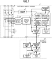
- FIG. 1 is a diagram illustrating an example of a configuration of an electronic circuit breaker according to a first embodiment of the present invention.
- an electronic circuit breaker 1 according to the first embodiment includes switch contacts 3 that open and close three-phase alternating current cable runs 2, a tripping device 4 that opens the switch contacts 3, current transformers 5 having primary sides inserted in the respective cable runs 2, a current detecting unit 6 that detects currents through the cable runs 2, a power supply unit 7 that generates power supply voltage Vc1 from secondary side outputs of the current transformers 5, power supply side connection terminals 8 connected with power supply side conductors, which are not illustrated and to which AC voltage is applied from a power supply, and load side connection terminals 9 connected with load side conductors, which are not illustrated and which are connected with loads.
- the electronic circuit breaker 1 also includes a communication unit 10 that communicates with an external device 50, a display unit 11 that displays parameter values that determine tripping characteristics, which are characteristics of tripping operation to open the switch contacts 3, and the like, a storage unit 12 that stores information used in the electronic circuit breaker 1, and a control unit 20 that controls the tripping device 4 and the display unit 11.
- a communication unit 10 that communicates with an external device 50
- a display unit 11 that displays parameter values that determine tripping characteristics, which are characteristics of tripping operation to open the switch contacts 3, and the like
- a storage unit 12 that stores information used in the electronic circuit breaker 1
- a control unit 20 that controls the tripping device 4 and the display unit 11.
- the switch contacts 3 include switch contacts 3 1 to 3 3 that respectively open and close three cable runs 2 1 to 2 3 , which constitute the cable runs 2.
- the switch contacts 3 1 to 3 3 each include a fixed contact, which is not illustrated, and a movable contact, which is not illustrated.
- the tripping device 4 separates the fixed contacts and the movable contacts in the contact state from each other on the basis of a command from the control unit 20, to disconnect the cable runs 2 1 to 2 3 and thus bring the electronic circuit breaker 1 into the off state.
- the electronic circuit breaker 1 includes a make-and-break mechanism, which is not illustrated, for moving the movable contacts, and the tripping device 4 is capable of separating the fixed contacts and the movable contacts in the contact state from each other by acting on the make-and-break mechanism.
- the current transformers 5 include current transformers 5 1 to 5 3 that are respectively inserted in the cable runs 2 1 to 2 3 , which constitute the cable runs 2.
- the current transformers 5 1 to 5 3 output, from secondary windings, currents directly proportional to the currents flowing through the cable runs 2 1 to 2 3 .
- the current detecting unit 6 detects the value of current output from each of the secondary windings of the current transformers 5 1 to 5 3 , and informs the control unit 20 of the detected current values.
- the values of currents detected by the current detecting unit 6 are instantaneous values, effective values, or mean values.
- the power supply unit 7 generates the power supply voltage Vc1 by using currents output from the respective secondary windings of the current transformers 5 1 to 5 3 .
- the power supply unit 7 is capable of generating the power supply voltage Vc1 by rectifying the currents output from the respective secondary windings of the current transformers 5 1 to 5 3 , combining the rectified currents, charging a capacitor with the resulting current, and stepping up or down the voltage of the capacitor.
- the power supply unit 7 supplies the power supply voltage Vc1 to the communication unit 10, the display unit 11, the storage unit 12, and the control unit 20.
- the configuration of the power supply unit 7 is not limited to that described above, and may be any configuration that generates the power supply voltage Vc1 by using the currents output from the respective secondary windings of the current transformers 5 1 to 5 3 .
- the communication unit 10 is a communication interface that communicates with the external device 50 by the frequency hopping spread spectrum method.
- the communication unit 10 is capable of receiving information transmitted from the external device 50, inputting the received information to the control unit 20, and transmitting information output from the control unit 20 to the external device 50.
- the communication method of the communication unit 10 is not limited to the frequency hopping spread spectrum method, and may be the direct spread spectrum method or a communication method other than spread spectrum methods.
- the external device 50 that communicates with the electronic circuit breaker 1 will now be described.
- the external device 50 includes a power supply unit 51 that generates and outputs power supply voltage Vc2, a communication unit 52 that communicates with the electronic circuit breaker 1, a control unit 53 that controls the entire external device 50, a display unit 54 that displays a screen based on control performed by the control unit 53, and an input unit 55 that receives an input operation performed by an operator.
- the power supply voltage Vc2 output from the power supply unit 51 is supplied to the communication unit 52, the control unit 53, and the display unit 54.
- the external device 50 can be connected with a connection terminal unit 14 of the electronic circuit breaker 1.
- the connection of the external device 50 with the connection terminal unit 14 causes the power supply voltage Vc2 of the power supply unit 51 to be supplied to the power supply unit 7 of the electronic circuit breaker 1 via the connection terminal unit 14, and causes the communication unit 52 to be communicably connected with the communication unit 10 of the electronic circuit breaker 1 via the connection terminal unit 14.
- the display unit 11 includes a display element, such as an electronic paper, capable of maintaining a displayed state in a state in which no power is supplied thereto.
- the display unit 11 is capable of rewriting the display screen on the basis of information output from the control unit 20 in a state in which the power supply voltage Vc1 is supplied from the power supply unit 7.
- the display unit 11 is capable of maintaining the state of the display screen while the supply of the power supply voltage Vc1 from the power supply unit 7 is stopped.
- the display unit 11 is thus capable of maintaining the displayed state even when the switch contacts 3 are in the off state.
- the display unit 11 is also capable of maintaining the displayed state even when the switch contacts 3 are in the on state and no currents flow through the cable runs 2.
- the storage unit 12 stores set values of the aforementioned tripping characteristics.
- the storage unit 12 is a nonvolatile storage unit capable of holding information stored in a state in which no power is supplied thereto, such as a flash memory, for example.
- the tripping characteristics are characteristics defined by the relation between the magnitude of an overcurrent flowing through the cable run 2 and a tripping operation time.
- the tripping characteristics of the electronic circuit breaker 1 have inverse time limit characteristics in which the operation time for the switch contacts 3 to open is shorter as the magnitudes of currents in excess of the rated current In in the cable runs 2 are larger.
- a region in which current is 115% or more of the rated current In and lower than short time limit tripping current Is is defined as a long time limit operation region
- a region in which current is equal to or higher than the short time limit tripping current Is and lower than instantaneous tripping current Ii is defined as a short time limit operation region
- a region in which current is equal to or higher than the instantaneous tripping current Ii is defined as an instantaneous operation region.
- the rated current In, the short time limit tripping current Is, and the instantaneous tripping current Ii mentioned above, and a long time limit operation time T L and a short time limit operation time T S are stored as a plurality of parameter values that determine the tripping characteristics.
- pre-alarm pick up current Ip is also stored as a parameter value in the electronic circuit breaker 1.
- the parameter values that determine the tripping characteristics may also be referred to as set characteristic values.
- the rated current In is a rated value of currents flowing through the cable runs 2 in the electronic circuit breaker 1.
- the short time limit tripping current Is is a current value that determines the aforementioned inverse time limit characteristics, and is expressed as a percentage of the rated current In.
- the instantaneous tripping current Ii is a current value at which instantaneous tripping is performed, and is expressed as a percentage of the rated current In.
- the short time limit operation time Ts is a time from when the value of current flowing through the cable run 2 reaches the short time limit operation region until when the tripping operation is completed in a case where a state in which the value of the current flowing through the cable run 2 is in the short time limit operation region continues.
- the long time limit operation time T L is a time from when the value of the current flowing through the cable run 2 reaches the long time limit operation region until when the tripping operation is completed in a case where a state in which the value of the current flowing through the cable run 2 is in the long time limit operation region continues.
- the pre-alarm pick up current Ip is a current value at which a pre-alarm function is started, and is expressed as a percentage of the rated current In.
- the pre-alarm function is a function of outputting an alarm when a load current that is current flowing through the cable run 2 exceeds the pre-alarm pick up current Ip.
- An example of the alarm of the pre-alarm function is an alarm signal output from a relay contact, which is not illustrated and is provided in the electronic circuit breaker 1, on the basis of control performed by the control unit 20.
- FIG. 2 is a table illustrating an example of a set value table stored in the storage unit according to the first embodiment.
- the set value table is information associating type information with the set characteristic values.
- the type information illustrated in FIG. 2 is information representing the type of a set value included in the tripping characteristics, and the set characteristic values illustrated in FIG. 2 are set values of the aforementioned tripping characteristics.
- the rated current In is set to 300 A
- the short time limit tripping current I S is set to 400%
- the instantaneous tripping current Ii is set to 1000%
- the long time limit operation time T L is set to 12 seconds
- the short time limit operation time Ts is set to 0.3 seconds
- the pre-alarm pick up current Ip is set to 85%.
- the set value table is not limited to the example illustrated in FIG. 2 .
- the set characteristic values may be stored at preset addresses in the storage unit 12.
- the control unit 20 includes an overcurrent determining unit 21 that determines an overcurrent through the cable run 2 on the basis of the value of current detected by the current detecting unit 6, a tripping control unit 22 that causes the tripping device 4 to open the switch contacts 3 when an overcurrent of the cable run 2 is determined by the overcurrent determining unit 21, a set value changing unit 23 that changes the set characteristic values stored in the storage unit 12, and a display control unit 24 that displays the set characteristic values stored in the storage unit 12, and the like on the display unit 11.
- the display control unit 24 When supply of the power supply voltage Vc1 from the power supply unit 7 is started, the display control unit 24 reads the set characteristic values stored in the storage unit 12, generates information on a set characteristic value display screen including the read set characteristic values, and displays the set characteristic value display screen on the display unit 11. Because the display unit 11 has a nonvolatile display element, the set characteristic value display screen displayed on the display unit 11 by the display control unit 24 is maintained even after the supply of the power supply voltage Vc1 to the display unit 11 is stopped. Thus, the set characteristic values can be checked even while no currents flow through the cable runs 2, and the set characteristic values can be checked even while the switch contacts 3 are in the off state.
- FIG. 3 is a diagram illustrating an example of a set characteristic value display screen according to the first embodiment.
- a set characteristic value display screen 31 illustrated in FIG. 3 displays a plurality of set characteristic values including the rated current In, the short time limit tripping current I S , the instantaneous tripping current Ii, the long time limit operation time T L , the short time limit operation time T S , and the pre-alarm pick up current Ip.
- the respective set characteristic values are displayed in a form of arc-shaped icons, and a boundary position between a black part and a white part of each of the icons indicates the magnitude of the set characteristic value. Because the magnitude of a set characteristic value is larger as the area of the black part in the corresponding icon is larger, the set characteristic values are easily recognized in a manner similar to a case of a rotational position of a rotational variable resistance switch.
- the electronic circuit breaker 1 is capable of updating the set characteristic values stored in the storage unit 12 from the external device 50.
- the connection of the external device 50 with the connection terminal unit 14 of the electronic circuit breaker 1 causes the power supply voltage Vc2 of the power supply unit 51 to be supplied to the power supply unit 7 of the electronic circuit breaker 1 via the connection terminal unit 14.
- the power supply unit 7 generates the power supply voltage Vc1 such that the magnitude of the power supply voltage Vc1 is equal to a reference value Vs.
- the power supply unit 7 can generate the power supply voltage Vc1 by using the higher of the value of the voltage generated by using the currents flowing through the cable runs 2 and the value of the power supply voltage Vc2.
- the power supply unit 7 may have such a configuration in which, when the power supply voltage Vc1 equal to the reference value Vs cannot be generated by using the currents flowing through the cable runs 2, the power supply unit 7 generates the power supply voltage Vc1 by using the power supply voltage Vc2 supplied from the external device 50.
- FIG. 4 is a diagram illustrating an example of a set characteristic value change screen according to the first embodiment.
- a set characteristic value change screen 32 illustrated in FIG. 4 displays input boxes 33 to 38 for entering respective changed values of the rated current In, the short time limit tripping current Is, the instantaneous tripping current Ii, the long time limit operation time T L , the short time limit operation time T S , and the pre-alarm pick up current Ip, and a check button 39 for checking an operating characteristic curve obtained with the changed values input in the input boxes 33 to 38.
- the operator inputs changed values of the set characteristic values into the input boxes 33 to 38 through input operation to the input unit 55 of the external device 50, so that the set value changing unit 23 causes the display unit 11 to display the changed values of the set characteristic values in the input boxes 33 to 38.
- the set value changing unit 23 informs the display control unit 24 of the changed values of the set characteristic values input in the input boxes 33 to 38.
- the display control unit 24 generates information on an update check screen including the operating characteristic curve of the changed set characteristic values on the basis of the changed values of the set characteristic values of which the display control unit 24 is informed by the set value changing unit 23.
- the set value changing unit 23 then causes the display unit 11 to display the update check screen.
- FIG. 5 is a diagram illustrating an example of an update check screen according to the first embodiment.
- An update check screen 41 illustrated in FIG. 5 displays a graph 42, an enter button 43, and a cancel button 44.
- the graph 42 includes a current operating characteristic curve and an operating characteristic curve of the changed set characteristic values.
- the vertical axis of the graph 42 represents the tripping operation time, and the horizontal axis of the graph 42 represents the magnitude of an overcurrent flowing through the cable run 2.
- the graph 42 enables the operator to easily know the tripping characteristics before and after a change.
- the set value changing unit 23 When the operator operates the enter button 43, the set value changing unit 23 is informed of update confirmation information indicating the operation of the enter button 43 by the external device 50. Upon being informed of the update confirmation information, the set value changing unit 23 stores the changed values of the set characteristic values input in the input boxes 33 to 38 into the storage unit 12 to update the set characteristic values stored in the storage unit 12.
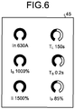
- FIG. 6 is a diagram illustrating an example of an updated set characteristic value display screen according to the first embodiment.
- a set characteristic value display screen 45 illustrated in FIG. 6 displays a state in which the set values other than the pre-alarm pick up current Ip are changed from the state of the set characteristic value display screen 31 illustrated in FIG. 3 .
- the set value changing unit 23 is informed of cancellation information indicating the operation of the cancel button 44 by the external device 50.
- the set value changing unit 23 deletes the changed values of the set characteristic values that are held, and requests the display control unit 24 to display the set characteristic value change screen on the display unit 11.
- the display control unit 24 displays the set characteristic value change screen on the display unit 11 on the basis of the request from the set value changing unit 23.
- the set value changing unit 23 can request the display control unit 24 to display, on the display unit 11, the set characteristic value change screen including the changed values of the set characteristic values that are held without deleting the changed values of the set characteristic values that are held. This enables the operator to work on changing the set characteristic values from a state with changed values as previously input.
- FIG. 7 is a flowchart illustrating an example of processes performed by the control unit 20 according to the first embodiment.
- the control unit 20 determines whether or not it is a timing for updating display of set characteristic values (step S10).
- the timing for updating display of the set characteristic values is a timing when supply of the power supply voltage Vc1 from the power supply unit 7 is started and the control unit 20 thus starts operating, or a timing when the set characteristic values stored in the storage unit 12 are updated, for example.
- step S10 If it is determined to be the timing for updating display of the set characteristic values (step S10: Yes), the control unit 20 sets a set characteristic value display screen as the display screen of the display unit 11 (step S11).
- step S11 the control unit 20 sets the set characteristic value display screen as the display screen of the display unit 11 by reading the set characteristic values stored in the storage unit 12 and rewriting the display screen of the display unit 11 to the set characteristic value display screen on the basis of the read set characteristic values. Note that, even when the display screen of the display unit 11 is a set characteristic value display screen, the control unit 20 overwrites the display screen of the display unit 11 by outputting information on the set characteristic value display screen based on the read set characteristic values to the display unit 11.
- step S11 determines whether or not the external device 50 is connected (step S12).
- step S12 the control unit 20 determines that the external device 50 is connected when communication with the external device 50 via the communication unit 10 is enabled.
- step S13 the control unit 20 performs a process of updating the set characteristic values.
- the process of updating the set characteristic values in step S13 is a process in which the control unit 20 updates the set characteristic values stored in the storage unit 12 on the basis of information transmitted from the external device 50, and corresponds to processes in steps S20 to S23 in FIG. 8 .
- step S13 When the process in step S13 is terminated or if the external device 50 is determined not to be connected (step S12: No), the control unit 20 determines whether or not an overcurrent is present in the cable runs 2 (step S14). If an overcurrent is determined to be present (step S14: Yes), the control unit 20 performs a tripping process (step S15). The tripping process in step S15 is performed by controlling the tripping device 4 on the basis of the set characteristic values stored in the storage unit 12.
- the control unit 20 causes the tripping devices 4 to open the switch contacts 3 when an overcurrent of 400% of the rated current In flows through the cable run 2 for 0.3 seconds or longer. In this manner, the tripping device 4 is controlled on the basis of the set characteristic values stored in the storage unit 12.
- step S15 When the process in step S15 is terminated or if it is determined that no overcurrent is present (step S14: No), the control unit 20 terminates the processes illustrated in FIG. 7 . Note that the control unit 20 repeats the processes illustrated in FIG. 7 . In addition, the control unit 20 can also perform the processes in steps S10 and S11, the processes in steps S12 and S13, and the processes in steps S14 and S15 in parallel with each other.
- FIG. 8 is a flowchart illustrating an example of the process of updating the set characteristic values in step S13.
- the control unit 20 sets a set characteristic value change screen as the display screen of the display unit 11 (step S20).
- the control unit 20 sets the set characteristic value display screen as the display screen of the display unit 11 by rewriting the display screen of the display unit 11 to the set characteristic value change screen. Thereafter, the control unit 20 performs a process of receiving input of changed values of the set characteristic values (step S21) .
- the control unit 20 determines whether or not the changed values of the set characteristic values are confirmed (step S22). In step S22, the control unit 20 determines that the changed values are confirmed when the enter button 43 is operated, and determines that the changed values are not confirmed when the cancel button 44 is operated. If the changed values are determined not to be confirmed (step S22: No), the control unit 20 returns to the process in step S20.
- control unit 20 stores the changed values of the set characteristic values into the storage unit 12 to update the set characteristic values stored in the storage unit 12 (step S23), and terminates the process illustrated in FIG. 8 .
- FIG. 9 is a diagram illustrating an example of a hardware configuration of the communication unit 10, the display unit 11, the storage unit 12, and the control unit 20 of the electronic circuit breaker 1 according to the first embodiment.
- the electronic circuit breaker 1 is a computer including a processor 101, a memory 102, a display 103, and an interface circuit 104.
- the processor 101, the memory 102, the display 103, and the interface circuit 104 are capable of transmitting and receiving data to and from each other via a bus 105.
- the communication unit 10 is implemented by the interface circuit 104
- the display unit 11 is implemented by the display 103
- the storage unit 12 is implemented by the memory 102.
- the processor 101 implements the functions of the overcurrent determining unit 21, the tripping control unit 22, the set value changing unit 23, and the display control unit 24 by reading and executing an OS and processing programs stored in the memory 102.
- the processor 101 can also read an OS and processing programs from one or more storage media including a magnetic disk, a universal serial bus (USB) memory, an optical disk, a compact disc, and a digital versatile disc (DVD) via an interface, which is not illustrated, store the read OS and processing programs in the memory 102, and execute the stored OS and processing programs.
- An optical disk, a compact disc, and a DVD are recording media in which computer-readable programs are recorded.
- the processor 101 is an example of a processing circuit and includes one or more of a CPU, a digital signal processor (DSP), and a system large scale integration (LSI).
- the memory 102 which is a storage area used as a work area of the processor 101, is a nonvolatile or volatile semiconductor memory typified by a random access memory (RAM).
- the electronic circuit breaker 1 includes the switch contacts 3 for opening and closing the cable runs 2, the current detecting unit 6 that detects currents flowing through the cable runs 2, the tripping device 4 that opens the switch contacts 3, the communication unit 10 that receives set characteristic values from the external device 50, the display unit 11 capable of displaying the set characteristic values, and the control unit 20 that controls the tripping device 4 on the basis of the currents detected by the current detecting unit 6 and the set characteristic values, and displays the set characteristic values on the display unit 11.
- the control unit 20 that controls the tripping device 4 on the basis of the currents detected by the current detecting unit 6 and the set characteristic values, and displays the set characteristic values on the display unit 11.
- the electronic circuit breaker 1 includes the power supply unit 7 that generates the power supply voltage Vc1 for driving the display unit 11, the communication unit 10, and the control unit 20 by using currents flowing through the cable runs 2.
- the display unit 11 is capable of maintaining a displayed state in the state in which the power supply voltage Vc1 is not supplied from the power supply unit 7, that is, in the state in which no power is supplied thereto.
- the display unit 11 is capable of maintaining the state in which the set characteristic values are displayed.
- the power supply unit 7 in the state in which no currents flow through the cable runs 2, the power supply unit 7 generates the power supply voltage Vc1 on the basis of voltage supplied from the external device, i.e., on the basis of the power supply voltage Vc2 supplied from the external device 50 that generates power supply voltage.
- the set characteristic values can be received from the external device 50 and displayed on the display unit 11 or can be updated.
- a second embodiment is different from the first embodiment in that, when power supply voltage output from the power supply unit of the electronic circuit breaker becomes low, the display screen is changed and a process of updating set characteristic values is stopped.
- components having similar functions to those in the first embodiment will be represented by the same reference numerals, the description thereof will not be repeated, and the description will be focused on the difference from the electronic circuit breaker 1 of the first embodiment.
- FIG. 10 is a diagram illustrating an example of a configuration of an electronic circuit breaker according to the second embodiment.
- an electronic circuit breaker 1A according to the second embodiment is different from the electronic circuit breaker 1 in that the electronic circuit breaker 1A includes a power supply unit 7A, a voltage detecting unit 17, and a control unit 20A instead of the power supply unit 7 and the control unit 20A.
- the power supply unit 7A includes a voltage generating unit 15 that generates the power supply voltage Vc1, and a power storing unit 16 that stores power on the basis of the power supply voltage Vc1 output from the voltage generating unit 15.
- the voltage generating unit 15 has a configuration similar to that of the power supply unit 7.
- the power storing unit 16 includes a capacitor to which the power supply voltage Vc1 from the voltage generating unit 15 is applied, and power is stored in the capacitor.
- the power of the power supply unit 51 of the external device 50 is supplied to the power supply unit 7A, and the voltage of the power storing unit 16 increases.
- the power supply voltage Vc1 output from the power supply unit 7A increases, bringing the communication unit 10 and the control unit 20A into an operable state, and communication between the control unit 20A and the external device 50 is started via the communication unit 10.
- the capacitance of the capacitor of the power storing unit 16 is set to such a value with which, in a case where the external device 50 is disconnected from the electronic circuit breaker 1A when the switch contacts 3 are in the off state, the time from when the power supply voltage Vc1 output from the power storing unit 16 becomes equal to or lower than a threshold Vth1 until when the power supply voltage Vc1 becomes smaller than a threshold Vth2 is equal to or longer than a preset time Ta.
- the preset time Ta is several to several tens of milliseconds, for example.
- the threshold Vth1 is a value smaller than the reference value Vs and larger than the threshold Vth2.
- the power supply unit 7A is not limited to the configuration illustrated in FIG. 10 .
- the capacitor of the voltage generating unit 15 can correspond to the power storing unit 16.
- the capacitance of the capacitor of the voltage generating unit 15 that functions as the power storing unit 16 is set to such a value with which, in the case where the external device 50 is disconnected from the electronic circuit breaker 1A when the switch contacts 3 are in the off state, the time from the timing when the power supply voltage Vc1 output from the power storing unit 16 becomes equal to or lower than the threshold Vth1 until the timing when the power supply voltage Vc1 becomes smaller than the threshold Vth2 is equal to or longer than the preset time Ta.
- the power supply unit 7A may have a configuration in which the power storing unit 16 is provided in the voltage generating unit 15.
- the voltage detecting unit 17 detects the power supply voltage Vc1 output from the power supply unit 7A.
- the power supply voltage Vc1 detected by the voltage detecting unit 17 is an instantaneous value or a mean value of the power supply voltage Vc1.
- the control unit 20A includes the overcurrent determining unit 21, the tripping control unit 22, a set value changing unit 23A, and a display control unit 24A.
- the set value changing unit 23A does not perform the process of changing the set characteristic values when the power supply voltage Vc1 is equal to or lower than the threshold Vth1, and halts the process of changing the set characteristic values when the power supply voltage Vc1 has become equal to or lower than the threshold Vth1 from a state higher than the threshold Vth1 while the process of changing the set characteristic values is performed.
- the display control unit 24A reads the set characteristic values stored in the storage unit 12, generates information on a set characteristic value display screen including the read set characteristic values, and displays the set characteristic value display screen on the display unit 11.
- the switch contacts 3 in the electronic circuit breaker 1A When the switch contacts 3 in the electronic circuit breaker 1A are in the on state, load currents are flowing through the cable runs 2, and thus currents directly proportional to the load currents are supplied from the secondary sides of the current transformers 5 to the power supply unit 7A.
- the power supply unit 7A can therefore generate the power supply voltage Vc1 higher than the threshold Vth1. In the state in which the power supply voltage Vc1 higher than the threshold Vth1 is supplied to the communication unit 10, the display unit 11, the storage unit 12, and the control unit 20A, the process of changing the set characteristic values can be performed.
- the display control unit 24A can rewrite the display screen of the display unit 11 to a display screen of a different type on the basis of a request from the external device 50 input via the communication unit 10.
- the types of the display screen include one or more cable run state display screens in addition to the set characteristic value display screen, the set characteristic value change screen, and the update check screen described above.
- a cable run state display screen includes at least one of measured values of the load currents that are currents flowing through the cable runs 2, measured values of the voltages of the cable runs 2, and measured values of power consumptions that are powers consumed by loads via the cable runs 2.
- the electronic circuit breaker 1A includes a voltage detecting unit, which is not illustrated, for detecting the voltages of the cable runs 2, and that the control unit 20A is capable of acquiring measured values of the voltages of the cable runs 2 from the not-illustrated voltage detecting unit and acquiring measured values of the load currents flowing through the cable runs 2 from the current detecting unit 6.
- the control unit 20A is also capable of acquiring the measured values of the power consumptions from the measured values of the voltages and the measured values of the currents.
- the electronic circuit breaker 1A can be provided with a switching button, which is not illustrated, as an operation unit for switching between a set characteristic value display screen and a cable run state display screen or switching between cable run state display screens.
- a switching button which is not illustrated, as an operation unit for switching between a set characteristic value display screen and a cable run state display screen or switching between cable run state display screens.
- the control unit 20A can perform the aforementioned switching.
- the control unit 20A can perform the aforementioned switching on the basis of a request from the external device 50.
- the display control unit 24A rewrites the display screen of the display unit 11 to a set characteristic value display screen before the power supply voltage Vc1 becomes lower than the threshold Vth2. This prevents the display screen of the display unit 11 from being maintained in a state other than the set characteristic value display screen, for example.
- the display control unit 24A and the display unit 11 can operate when the power supply voltage Vc1 is equal to or higher than the threshold Vth2, and the power storing unit 16 holds power for a period from when the power supply voltage Vc1 becomes equal to or lower than the threshold Vth1 until when the power supply voltage Vc1 becomes smaller than the threshold Vth2.
- the power supply voltage Vc1 lowers rapidly to a voltage lower than the threshold Vth2 if the power storing unit 16 is not present.
- the display control unit 24A is capable of rewriting the display screen of the display unit 11 to a set characteristic value display screen regardless of the extent to which the load currents are lowered.
- the display control unit 24A rewrites the display screen of the display unit 11 to a set characteristic value display screen before the power supply voltage Vc1 becomes lower than the threshold Vth2, as described above. This prevents the display screen of the display unit 11 from being maintained in a state other than the set characteristic value display screen.
- FIG. 11 is a flowchart illustrating an example of a process of updating set characteristic values performed by the control unit according to the second embodiment.
- the control unit 20A determines whether or not the power supply voltage Vc1 is higher than the threshold Vth1 (step S31). If the power supply voltage Vc1 is determined to be higher than the threshold Vth1 (step S31: Yes), the control unit 20A proceeds to the process in step S32.
- the processes in steps S32 to S35 are similar to those in steps S20 to S23 illustrated in FIG. 8 .
- step S31: No If the power supply voltage Vc1 is determined not to be higher than the threshold Vth1 (step S31: No) or when the process in step S35 is terminated, the control unit 20A terminates the process illustrated in FIG. 11 .
- control unit 20A does not change the display screen of the display unit 11 in the state in which the power supply voltage Vc1 is equal to or lower than the threshold Vth1, and changes the display screen of the display unit 11 when the power supply voltage Vc1 has become higher than the threshold Vth1. This enables the display screen of the display unit 11 to be changed in a state in which the power supply voltage Vc1 is stable.
- control unit 20A halts the process illustrated in FIG. 11 when the power supply voltage Vc1 has become equal to or lower than the threshold Vth1 during the processes in steps S32 to S35. This prevents the set characteristic values from being set to erroneous values by malfunction due to lowering of the power supply voltage Vc1.
- FIG. 12 is a flowchart illustrating an example of a process performed by the control unit according to the second embodiment when the power supply voltage is lowered, which is a process repeated by the control unit 20A. As illustrated in FIG. 12 , the control unit 20A determines whether or not the power supply voltage Vc1 has become equal to or lower than the threshold Vth1 (step S41).
- step S41 If the power supply voltage Vc1 is determined to have become equal to or lower than the threshold Vth1 (step S41: Yes), the control unit 20A sets an error screen as the display screen of the display unit 11 (step S42).
- step S42 the control unit 20A sets the error screen as the display screen of the display unit 11 by rewriting the display screen of the display unit 11 to the error screen.
- FIG. 13 is a diagram illustrating an example of the error screen.
- An error screen 46 illustrated in FIG. 13 displays words indicating power failure and words indicating that the processing is stopped.
- step S43 the control unit 20A sets a set characteristic value display screen as the display screen within the preset time Ta from when the power supply voltage Vc1 has become equal to or lower than the threshold Vth1 (step S43).
- step S43 the control unit 20A sets the set characteristic value display screen as the display screen by rewriting the display screen of the display unit 11 to the set characteristic value display screen on the basis of the set characteristic values read from the storage unit 12 in a manner similar to the process in step S11.
- step S41: No If the power supply voltage Vc1 is determined not to have become equal to or lower than the threshold Vth1 (step S41: No) or when the process in step S43 is terminated, the control unit 20A terminates the process illustrated in FIG. 12 .
- control unit 20A rewrites the display screen of the display unit 11 to a set characteristic value display screen displaying the set characteristic values stored in the storage unit 12 when the power supply voltage Vc1 has become equal to or lower than the threshold Vth1. This enables the set characteristic values and the values displayed on the display unit 11 to be coincident with each other in the case where the power supply voltage Vc1 is lowered while the operator is carrying out the process of updating the set characteristic values.
- control unit 20A stores the changed values of the set characteristic values without deleting the currently applied set characteristic values until the update process is confirmed.
- the control unit 20A can delete the currently applied set characteristic values from the storage unit 12 and use the changed values of the set characteristic values stored in the storage unit 12 as the updated set characteristic values.
- control unit 20A reads the currently applied set characteristic values from the storage unit 12 instead of the changed values of the set characteristic values.
- the control unit 20A can rewrite the display screen of the display unit 11 to the set characteristic value display screen displaying the read set characteristic values.
- the control unit 20A does not delete the changed values of the set characteristic values stored in the storage unit 12. Then, when the operator carries out the process of updating the set characteristic values again, a set characteristic value change screen including the changed values of the set characteristic values stored in the storage unit 12 can be displayed on the display unit 11. As a result, the burden on the operator in the process of updating the set characteristic values can be reduced. Note that, in the case where the power supply voltage Vc1 has become equal to or lower than the threshold Vth1 before the operator confirms the process of updating the set characteristic values, the control unit 20A can also delete the changed values of the set characteristic values stored in the storage unit 12.
- the processor 101 can implement the functions of the overcurrent determining unit 21, the tripping control unit 22, the set value changing unit 23A, and the display control unit 24A by reading and executing programs stored in the memory 102 that functions as the storage unit 12.
- the power supply unit 7A of the electronic circuit breaker 1A includes the power storing unit 16 that stores power on the basis of the currents flowing through the cable runs 2 or the power supply voltage Vc2 supplied from the external device 50, and outputs the power supply voltage Vc1 on the basis of the power stored in the power storing unit 16 when current flowing through the cable run 2 or the power supply voltage Vc2 supplied from the external device 50 is lowered.
- the control unit 20A determines whether or not the power supply voltage Vc1 has become equal to or lower than the threshold Vth1, and performs a process of displaying the set characteristic values on the display unit 11 if the power supply voltage Vc1 is determined to have become equal to or lower than the threshold Vth1.
- the display screen of the display unit 11 can be prevented from being maintained in a state other than the set characteristic value display screen.
- a third embodiment is different from the second embodiment in that a change in set characteristic values is permitted on the basis of a closing state of the electronic circuit breaker.
- components having similar functions to those in the second embodiment will be represented by the same reference numerals, the description thereof will not be repeated, and the description will be focused on the difference from the electronic circuit breaker 1A of the second embodiment.
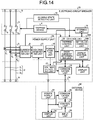
- FIG. 14 is a diagram illustrating an example of a configuration of an electronic circuit breaker according to the third embodiment.
- an electronic circuit breaker 1B according to the third embodiment is different from the electronic circuit breaker 1A in that the electronic circuit breaker 1B includes a closing state detecting unit 18 and a control unit 20B instead of the control unit 20A.
- the closing state detecting unit 18 detects the closing state of the electronic circuit breaker 1B, and informs the control unit 20B of the detection.
- the closing state of the electronic circuit breaker 1B includes an on state, an off state, and a tripped state.
- the on state of the electronic circuit breaker 1B means that the switch contacts 3 are in the on state.
- the off state of the electronic circuit breaker 1B means that the switch contacts 3 are brought into the off state by a manual lever, which is not illustrated, of the electronic circuit breaker 1B.
- the tripped state of the electronic circuit breaker 1B means that the switch contacts 3 are brought into the off state by the tripping device 4.
- the control unit 20B includes the overcurrent determining unit 21, the tripping control unit 22, a set value changing unit 23B, and the display control unit 24A.
- the set value changing unit 23B performs the process of changing set characteristic values when the closing state of the electronic circuit breaker 1B is the on state, and does not perform the process of changing set characteristic values when the closing state of the electronic circuit breaker 1B is the off state or the tripped state. As a result, the operator cannot change the set characteristic values while the cable runs 2 are in the conducting state, which can prevent occurrence of unnecessary operation.
- FIG. 15 is a flowchart illustrating an example of a process of updating set characteristic values performed by the control unit according to the third embodiment.
- the control unit 20B determines whether or not the power supply voltage Vc1 is higher than the threshold Vth1 (step S51). If the power supply voltage Vc1 is determined to be higher than the threshold Vth1 (step S51: Yes), the control unit 20B determines whether or not the closing state of the electronic circuit breaker 1B is the on state (step S52).
- step S52 If the closing state of the electronic circuit breaker 1B is determined to be the on state (step S52: Yes), the control unit 20B sets an alarm screen as the display screen of the display unit 11 by rewriting the display screen of the display unit 11 to an alarm screen and displaying the alarm screen on the display unit 11 (step S53). In step S53, the control unit 20B sets the alarm screen as the display screen of the display unit 11 by rewriting the display screen of the display unit 11 to the alarm screen.
- FIG. 16 is a diagram illustrating an example of an alarm screen. An alarm screen 47 illustrated in FIG. 16 includes information indicating that a change in the set characteristic values is not permitted.
- step S54 the control unit 20B sets a set characteristic value display screen as the display screen (step S54).
- step S54 the control unit 20B sets the set characteristic value display screen as the display screen by rewriting the display screen of the display unit 11 to the set characteristic value display screen on the basis of the set characteristic values read from the storage unit 12 in a manner similar to the process in step S43.
- step S52 determines whether the closing state of the electronic circuit breaker 1B is determined not to be the on state (step S52: No).
- the control unit 20B proceeds to the process in step S55.
- the processes in steps S55 to S58 are similar to those in steps S20 to S23 illustrated in FIG. 8 . If the power supply voltage Vc1 is determined not to be higher than the threshold Vth1 (step S51: No) or when the process in step S58 is terminated, the control unit 20B terminates the process illustrated in FIG. 15 .
- control unit 20B is capable of preventing the process of changing set characteristic values when the closing state of the electronic circuit breaker 1B is the on state. This can avoid, when the closing state of the electronic circuit breaker 1B is the on state, unnecessary tripping operation performed by the electronic circuit breaker 1B owing to a change in the set characteristic values.
- control unit 20B may be configured not to permit set characteristic values to become smaller but to permit set characteristic values to become larger when the closing state of the electronic circuit breaker 1B is the on state.
- an example of the hardware configuration of the communication unit 10, the display unit 11, the storage unit 12, and the control unit 20B of the electronic circuit breaker 1B according to the third embodiment is the same as that illustrated in FIG. 9 .
- the processor 101 can implement the functions of the overcurrent determining unit 21, the tripping control unit 22, the set value changing unit 23B, and the display control unit 24A by reading and executing programs stored in the memory 102 that functions as the storage unit 12.
- control unit 20B of the electronic circuit breaker 1B determines whether or not the switch contacts 3 are in an open state, and permits a change in set characteristic values from the external device 50 when the switch contacts 3 are determined to be in the open state. As a result, because the operator cannot change set characteristic values while the cable runs 2 are in the conducting state, occurrence of unnecessary tripping operation in the electronic circuit breaker 1B can be prevented.
- control unit 20B displays, on the display unit 11, information indicating that a change in set characteristic values is not permitted. As a result, the operator can easily know that the electronic circuit breaker 1B is in a state in which setting of set characteristic values cannot be performed.
- control unit 20B can additionally include information indicating that set characteristic values can be set in a set characteristic value display screen to be displayed on the display unit 11 when the power supply voltage Vc1 is determined to have become equal to or lower than the threshold Vth1.
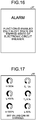
- FIG. 17 is a diagram illustrating an example of a set characteristic value display screen according to the third embodiment.
- a set characteristic value display screen 48 illustrated in FIG. 17 additionally displays information indicating that the set characteristic values can be set.
- control unit 20B can additionally include information indicating that set characteristic values cannot be set in a set characteristic value display screen to be displayed on the display unit 11 when the power supply voltage Vc1 has become higher than the threshold Vth1 from the state equal to or lower than the threshold Vth1 in a state in which the set characteristic value display screen 48 illustrated in FIG. 17 is displayed on the display unit 11.
- FIG. 18 is a diagram illustrating another example of a set characteristic value display screen according to the third embodiment.
- a set characteristic value display screen 49 illustrated in FIG. 18 additionally includes information indicating that set characteristic values cannot be set.
- the electronic circuit breakers 1, 1A, and 1B may be connected wirelessly with the external devices 50.
- power supply from the external devices 50 to the electronic circuit breakers 1, 1A, and 1B is performed through wireless radio transmission, and communication from the external devices 50 to the electronic circuit breakers 1, 1A, and 1B is performed through radio communication.
- power may be supplied from power supply devices other than the external devices 50 to the electronic circuit breakers 1, 1A, and 1B.
- timing for updating the display of set characteristic values is not limited to the timings described above.
- the control units 20, 20A, and 20B can generate display update timing at constant intervals.
- control units 20, 20A, and 20B can each display a screen similar to that displayed on the display unit 11 on the display unit 54 of the external device 50.
- the control units 20, 20A, and 20B each output information on the screen to be displayed on the display unit 11 to the external device 50 via the communication unit 10.
- the control unit 53 of the external device 50 can acquire the information on the screen via the communication unit 52, and display the screen on the display unit 54.
- the power supply units 7 and 7A each generate the power supply voltage Vc1 by using the currents flowing through the cable runs 2 in the examples described above
- the power supply units 7 and 7A may each be configured to generate the power supply voltage Vc1 on the basis of the voltages of the cable runs 2.
- the power supply units 7 and 7A each generate the power supply voltage Vc1 by using the voltages between the switch contacts 3 and the load side connection terminals 9.
- the electronic circuit breakers 1, 1A, and 1B may each be provided with a first power supply unit for supplying power supply voltage to the overcurrent determining unit 21 and the tripping control unit 22, and a second power supply for supplying power supply voltage to the set value changing unit 23, 23A, or 23B and the display control unit 24A.
- the second power supply may be configured to generate power supply voltage by voltage supply from the external device 50.
- control units 20, 20A, and 20B each cause the tripping device 4 to open the switch contacts 3 on the basis of set values of the tripping characteristics relating to overcurrent when overcurrent flows through the cable run 2 in the examples described above
- control units 20, 20A, and 20B can each also cause the tripping device 4 to open the switch contacts 3 on the basis of set values of the tripping characteristics relating to leakage current when electric leakage is detected.
- the voltages of the cable runs 2 are input to the current detecting unit 6 of each of the electronic circuit breakers 1, 1A, and 1B, and the current detecting unit 6 can detect the load currents of the cable runs 2 and the leakage current of the cable runs 2 by using the voltages of the cable runs 2 and the currents flowing through the cable runs 2.
- the set values of the tripping characteristics relating to leakage current are stored in the storage unit 12 of each of the electronic circuit breakers 1, 1A, and 1B.
- the control units 20, 20A, and 20B can then each cause the tripping device 4 to open the switch contacts 3 on the basis of the leakage current detected by the current detecting unit 6 and the set values of the tripping characteristics relating to leakage current stored in the storage unit.
- the control units 20, 20A, and 20B can each display, on the display unit 11, a set characteristic value display screen including the set values of the tripping characteristics relating to overcurrent and the set values of the tripping characteristics relating to leakage current.
- the electronic circuit breakers 1, 1A, and 1B can also function as earth leakage circuit breakers.
Landscapes
- Breakers (AREA)
- Emergency Protection Circuit Devices (AREA)
Abstract
Description
- The present invention relates to an electronic circuit breaker capable of adjusting tripping characteristics, which are characteristics of tripping operation to open switch contacts.
- In related art, an electronic circuit breaker capable of adjusting tripping characteristics has a configuration capable of checking and adjusting set characteristic values that are parameter values determining tripping characteristics. For example, an electronic circuit breaker taught in
Patent Literature 1 is provided with a variable resistance switch for adjusting the values of characteristics parameters, and capable of checking set characteristic values from the position of a knob including the variable resistance switch. - In addition, an electronic circuit breaker taught in
Patent Literature 2 includes a keypad for adjusting set characteristic values, and a display for displaying the set characteristic values. -
- Patent Literature 1: Japanese Patent Application Laid-open No.
S62-64215 - Patent Literature 2: Japanese Patent Application Laid-open No.
H02-119026 - Electronic circuit breakers, however, have been becoming smaller in size, which causes a problem in that it has been becoming difficult to allow space for providing a variable resistance switch and to allow for space for providing both a display and a keypad.
- In addition, in the electronic circuit breaker taught in
Patent Literature 2, although a unit including a display and a keypad is removable, set characteristic value cannot be checked with the electronic circuit breaker in the state in which the unit is removed. - The present invention has been made in view of the above, and an object thereof is to provide an electronic circuit breaker capable of adjusting tripping characteristics without providing a space for placing a setting unit such as a variable resistance switch and a keypad, and capable of checking set characteristic values.
- To solve the problem and achieve the object described above, an electronic circuit breaker according to an aspect of the present invention includes: a switch contact to open and close a cable run; a current detecting unit to detect current flowing through the cable run; a tripping device to open the switch contact; a communication unit to receive, from an external device, a parameter value determining characteristics of tripping operation to open the switch contact; a display unit capable of displaying the parameter value; and a control unit to cause the tripping device to open the switch contact on a basis of the current detected by the current detecting unit and the parameter value, and display the parameter value on the display unit.
- The present invention provides advantageous effects of enabling adjustment of tripping characteristics without providing a space for placing a setting unit such as a variable resistance switch and a keypad, and enabling checking of set characteristic values.
-
-
FIG. 1 is a diagram illustrating an example of a configuration of an electronic circuit breaker according to a first embodiment. -
FIG. 2 is a table illustrating an example of a set value table stored in a storage unit according to the first embodiment. -
FIG. 3 is a diagram illustrating an example of a set characteristic value display screen according to the first embodiment. -
FIG. 4 is a diagram illustrating an example of a set characteristic value change screen according to the first embodiment. -
FIG. 5 is a diagram illustrating an example of an update check screen according to the first embodiment. -
FIG. 6 is a diagram illustrating an example of an updated set characteristic value display screen according to the first embodiment. -
FIG. 7 is a flowchart illustrating an example of processes performed by a control unit according to the first embodiment. -
FIG. 8 is a flowchart illustrating an example of a process of updating set characteristic values according to the first embodiment. -
FIG. 9 is a diagram illustrating an example of a hardware configuration of a communication unit, a display unit, a storage unit, and a control unit of the electronic circuit breaker according to the first embodiment. -
FIG. 10 is a diagram illustrating an example of a configuration of an electronic circuit breaker according to a second embodiment. -
FIG. 11 is a flowchart illustrating an example of a process of updating set characteristic values performed by a control unit according to the second embodiment. -
FIG. 12 is a flowchart illustrating an example of a process performed by the control unit according to the second embodiment when a power supply voltage is lowered. -
FIG. 13 is a diagram illustrating an example of an error screen according to the second embodiment. -
FIG. 14 is a diagram illustrating an example of a configuration of an electronic circuit breaker according to a third embodiment. -
FIG. 15 is a flowchart illustrating an example of a process of updating set characteristic values performed by a control unit according to the third embodiment. -
FIG. 16 is a diagram illustrating an example of an alarm screen according to the third embodiment. -
FIG. 17 is a diagram illustrating another example of an alarm screen according to the third embodiment. -
FIG. 18 is a diagram illustrating another example of a set characteristic value display screen according to the third embodiment. - An electronic circuit breaker according to certain embodiments of the present invention will be described in detail below with reference to the drawings. Note that the present invention is not limited to the embodiments.
-
FIG. 1 is a diagram illustrating an example of a configuration of an electronic circuit breaker according to a first embodiment of the present invention. As illustrated inFIG. 1 , anelectronic circuit breaker 1 according to the first embodiment includesswitch contacts 3 that open and close three-phase alternating current cable runs 2, atripping device 4 that opens theswitch contacts 3,current transformers 5 having primary sides inserted in therespective cable runs 2, acurrent detecting unit 6 that detects currents through the cable runs 2, apower supply unit 7 that generates power supply voltage Vc1 from secondary side outputs of thecurrent transformers 5, power supplyside connection terminals 8 connected with power supply side conductors, which are not illustrated and to which AC voltage is applied from a power supply, and loadside connection terminals 9 connected with load side conductors, which are not illustrated and which are connected with loads. - The
electronic circuit breaker 1 also includes acommunication unit 10 that communicates with anexternal device 50, adisplay unit 11 that displays parameter values that determine tripping characteristics, which are characteristics of tripping operation to open theswitch contacts 3, and the like, astorage unit 12 that stores information used in theelectronic circuit breaker 1, and acontrol unit 20 that controls thetripping device 4 and thedisplay unit 11. - The
switch contacts 3 includeswitch contacts 31 to 33 that respectively open and close three cable runs 21 to 23, which constitute thecable runs 2. Theswitch contacts 31 to 33 each include a fixed contact, which is not illustrated, and a movable contact, which is not illustrated. When the fixed contacts and the movable contacts of therespective switch contacts 31 to 33 come in contact with each other, the power supplyside connection terminals 8 are electrically connected with the loadside connection terminals 9. Consequently, currents flow through the respective cable runs 21 to 23, and theelectronic circuit breaker 1 gets into a conducting state. - When the fixed contacts and the movable contacts of the
respective switch contacts 31 to 33 leave each other, theswitch contacts 3 are opened, and the power supplyside connection terminals 8 are electrically disconnected from the loadside connection terminals 9. Consequently, currents in the respective cable runs 21 to 23 are interrupted, and theelectronic circuit breaker 1 gets into a non-conducting state. Hereinafter, the state in which the fixed contacts and the movable contacts are in contact with each other will be referred to as an on state of theswitch contacts 3 or an on state of theelectronic circuit breaker 1, and the state in which the fixed contacts and the movable contacts are separated from each other will be referred to as an off state of theswitch contacts 3 or an off state of theelectronic circuit breaker 1. - The
tripping device 4 separates the fixed contacts and the movable contacts in the contact state from each other on the basis of a command from thecontrol unit 20, to disconnect the cable runs 21 to 23 and thus bring theelectronic circuit breaker 1 into the off state. Theelectronic circuit breaker 1 includes a make-and-break mechanism, which is not illustrated, for moving the movable contacts, and thetripping device 4 is capable of separating the fixed contacts and the movable contacts in the contact state from each other by acting on the make-and-break mechanism. - The
current transformers 5 includecurrent transformers 51 to 53 that are respectively inserted in the cable runs 21 to 23, which constitute the cable runs 2. Thecurrent transformers 51 to 53 output, from secondary windings, currents directly proportional to the currents flowing through the cable runs 21 to 23. - The
current detecting unit 6 detects the value of current output from each of the secondary windings of thecurrent transformers 51 to 53, and informs thecontrol unit 20 of the detected current values. The values of currents detected by the current detectingunit 6 are instantaneous values, effective values, or mean values. - The
power supply unit 7 generates the power supply voltage Vc1 by using currents output from the respective secondary windings of thecurrent transformers 51 to 53. For example, thepower supply unit 7 is capable of generating the power supply voltage Vc1 by rectifying the currents output from the respective secondary windings of thecurrent transformers 51 to 53, combining the rectified currents, charging a capacitor with the resulting current, and stepping up or down the voltage of the capacitor. Thepower supply unit 7 supplies the power supply voltage Vc1 to thecommunication unit 10, thedisplay unit 11, thestorage unit 12, and thecontrol unit 20. Note that the configuration of thepower supply unit 7 is not limited to that described above, and may be any configuration that generates the power supply voltage Vc1 by using the currents output from the respective secondary windings of thecurrent transformers 51 to 53. - The
communication unit 10 is a communication interface that communicates with theexternal device 50 by the frequency hopping spread spectrum method. Thecommunication unit 10 is capable of receiving information transmitted from theexternal device 50, inputting the received information to thecontrol unit 20, and transmitting information output from thecontrol unit 20 to theexternal device 50. The communication method of thecommunication unit 10 is not limited to the frequency hopping spread spectrum method, and may be the direct spread spectrum method or a communication method other than spread spectrum methods. - The
external device 50 that communicates with theelectronic circuit breaker 1 will now be described. Theexternal device 50 includes apower supply unit 51 that generates and outputs power supply voltage Vc2, acommunication unit 52 that communicates with theelectronic circuit breaker 1, acontrol unit 53 that controls the entireexternal device 50, adisplay unit 54 that displays a screen based on control performed by thecontrol unit 53, and aninput unit 55 that receives an input operation performed by an operator. The power supply voltage Vc2 output from thepower supply unit 51 is supplied to thecommunication unit 52, thecontrol unit 53, and thedisplay unit 54. - The
external device 50 can be connected with aconnection terminal unit 14 of theelectronic circuit breaker 1. The connection of theexternal device 50 with theconnection terminal unit 14 causes the power supply voltage Vc2 of thepower supply unit 51 to be supplied to thepower supply unit 7 of theelectronic circuit breaker 1 via theconnection terminal unit 14, and causes thecommunication unit 52 to be communicably connected with thecommunication unit 10 of theelectronic circuit breaker 1 via theconnection terminal unit 14. - The description returns to the explanation of the
electronic circuit breaker 1. Thedisplay unit 11 includes a display element, such as an electronic paper, capable of maintaining a displayed state in a state in which no power is supplied thereto. Thedisplay unit 11 is capable of rewriting the display screen on the basis of information output from thecontrol unit 20 in a state in which the power supply voltage Vc1 is supplied from thepower supply unit 7. In addition, thedisplay unit 11 is capable of maintaining the state of the display screen while the supply of the power supply voltage Vc1 from thepower supply unit 7 is stopped. - The
display unit 11 is thus capable of maintaining the displayed state even when theswitch contacts 3 are in the off state. Thedisplay unit 11 is also capable of maintaining the displayed state even when theswitch contacts 3 are in the on state and no currents flow through the cable runs 2. - The
storage unit 12 stores set values of the aforementioned tripping characteristics. Thestorage unit 12 is a nonvolatile storage unit capable of holding information stored in a state in which no power is supplied thereto, such as a flash memory, for example. - The tripping characteristics are characteristics defined by the relation between the magnitude of an overcurrent flowing through the
cable run 2 and a tripping operation time. The tripping characteristics of theelectronic circuit breaker 1 have inverse time limit characteristics in which the operation time for theswitch contacts 3 to open is shorter as the magnitudes of currents in excess of the rated current In in the cable runs 2 are larger. Herein, a region in which current is 115% or more of the rated current In and lower than short time limit tripping current Is is defined as a long time limit operation region, a region in which current is equal to or higher than the short time limit tripping current Is and lower than instantaneous tripping current Ii is defined as a short time limit operation region, and a region in which current is equal to or higher than the instantaneous tripping current Ii is defined as an instantaneous operation region. - In the
electronic circuit breaker 1, the rated current In, the short time limit tripping current Is, and the instantaneous tripping current Ii mentioned above, and a long time limit operation time TL and a short time limit operation time TS are stored as a plurality of parameter values that determine the tripping characteristics. In addition, pre-alarm pick up current Ip is also stored as a parameter value in theelectronic circuit breaker 1. Hereinafter, the parameter values that determine the tripping characteristics may also be referred to as set characteristic values. - The rated current In is a rated value of currents flowing through the cable runs 2 in the
electronic circuit breaker 1. The short time limit tripping current Is is a current value that determines the aforementioned inverse time limit characteristics, and is expressed as a percentage of the rated current In. The instantaneous tripping current Ii is a current value at which instantaneous tripping is performed, and is expressed as a percentage of the rated current In. - The short time limit operation time Ts is a time from when the value of current flowing through the
cable run 2 reaches the short time limit operation region until when the tripping operation is completed in a case where a state in which the value of the current flowing through thecable run 2 is in the short time limit operation region continues. The long time limit operation time TL is a time from when the value of the current flowing through thecable run 2 reaches the long time limit operation region until when the tripping operation is completed in a case where a state in which the value of the current flowing through thecable run 2 is in the long time limit operation region continues. - The pre-alarm pick up current Ip is a current value at which a pre-alarm function is started, and is expressed as a percentage of the rated current In. The pre-alarm function is a function of outputting an alarm when a load current that is current flowing through the
cable run 2 exceeds the pre-alarm pick up current Ip. An example of the alarm of the pre-alarm function is an alarm signal output from a relay contact, which is not illustrated and is provided in theelectronic circuit breaker 1, on the basis of control performed by thecontrol unit 20. -
FIG. 2 is a table illustrating an example of a set value table stored in the storage unit according to the first embodiment. As illustrated inFIG. 2 , the set value table is information associating type information with the set characteristic values. The type information illustrated inFIG. 2 is information representing the type of a set value included in the tripping characteristics, and the set characteristic values illustrated inFIG. 2 are set values of the aforementioned tripping characteristics. - In the set value table illustrated in
FIG. 2 , the rated current In is set to 300 A, the short time limit tripping current IS is set to 400%, the instantaneous tripping current Ii is set to 1000%, the long time limit operation time TL is set to 12 seconds, the short time limit operation time Ts is set to 0.3 seconds, and the pre-alarm pick up current Ip is set to 85%. Note that the set value table is not limited to the example illustrated inFIG. 2 . In addition, the set characteristic values may be stored at preset addresses in thestorage unit 12. - Referring back to
FIG. 1 , the description of thecontrol unit 20 is continued. Thecontrol unit 20 includes anovercurrent determining unit 21 that determines an overcurrent through thecable run 2 on the basis of the value of current detected by the current detectingunit 6, a trippingcontrol unit 22 that causes the trippingdevice 4 to open theswitch contacts 3 when an overcurrent of thecable run 2 is determined by theovercurrent determining unit 21, a setvalue changing unit 23 that changes the set characteristic values stored in thestorage unit 12, and adisplay control unit 24 that displays the set characteristic values stored in thestorage unit 12, and the like on thedisplay unit 11. - When supply of the power supply voltage Vc1 from the
power supply unit 7 is started, thedisplay control unit 24 reads the set characteristic values stored in thestorage unit 12, generates information on a set characteristic value display screen including the read set characteristic values, and displays the set characteristic value display screen on thedisplay unit 11. Because thedisplay unit 11 has a nonvolatile display element, the set characteristic value display screen displayed on thedisplay unit 11 by thedisplay control unit 24 is maintained even after the supply of the power supply voltage Vc1 to thedisplay unit 11 is stopped. Thus, the set characteristic values can be checked even while no currents flow through the cable runs 2, and the set characteristic values can be checked even while theswitch contacts 3 are in the off state. -
FIG. 3 is a diagram illustrating an example of a set characteristic value display screen according to the first embodiment. A set characteristicvalue display screen 31 illustrated inFIG. 3 displays a plurality of set characteristic values including the rated current In, the short time limit tripping current IS, the instantaneous tripping current Ii, the long time limit operation time TL, the short time limit operation time TS, and the pre-alarm pick up current Ip. - In the example illustrated in
FIG. 3 , the respective set characteristic values are displayed in a form of arc-shaped icons, and a boundary position between a black part and a white part of each of the icons indicates the magnitude of the set characteristic value. Because the magnitude of a set characteristic value is larger as the area of the black part in the corresponding icon is larger, the set characteristic values are easily recognized in a manner similar to a case of a rotational position of a rotational variable resistance switch. - The
electronic circuit breaker 1 according to the first embodiment is capable of updating the set characteristic values stored in thestorage unit 12 from theexternal device 50. As described above, the connection of theexternal device 50 with theconnection terminal unit 14 of theelectronic circuit breaker 1 causes the power supply voltage Vc2 of thepower supply unit 51 to be supplied to thepower supply unit 7 of theelectronic circuit breaker 1 via theconnection terminal unit 14. - When the
switch contacts 3 are in the off state or when theswitch contacts 3 are in the on state and the cable runs 2 are in the non-conducting state, no currents are output from the secondary windings of thecurrent transformers 51 to 53 to thepower supply unit 7, but the power supply voltage Vc2 is output from theexternal device 50 to thepower supply unit 7. This enables thepower supply unit 7 to generate the power supply voltage Vc1 on the basis of the power supply voltage Vc2, and to cause thecommunication unit 10, thedisplay unit 11, thestorage unit 12, and thecontrol unit 20 to operate on the basis of the power supply voltage Vc1. - In addition, the
power supply unit 7 generates the power supply voltage Vc1 such that the magnitude of the power supply voltage Vc1 is equal to a reference value Vs. When currents flow through the cable runs 2 and the power supply voltage Vc2 is supplied from theexternal device 50, thepower supply unit 7 can generate the power supply voltage Vc1 by using the higher of the value of the voltage generated by using the currents flowing through the cable runs 2 and the value of the power supply voltage Vc2. In addition, thepower supply unit 7 may have such a configuration in which, when the power supply voltage Vc1 equal to the reference value Vs cannot be generated by using the currents flowing through the cable runs 2, thepower supply unit 7 generates the power supply voltage Vc1 by using the power supply voltage Vc2 supplied from theexternal device 50. - When the
external device 50 is connected with theelectronic circuit breaker 1, thedisplay control unit 24 can output information on a set characteristic value change screen to thedisplay unit 11 to display the set characteristic value change screen on thedisplay unit 11.FIG. 4 is a diagram illustrating an example of a set characteristic value change screen according to the first embodiment. - A set characteristic
value change screen 32 illustrated inFIG. 4 displaysinput boxes 33 to 38 for entering respective changed values of the rated current In, the short time limit tripping current Is, the instantaneous tripping current Ii, the long time limit operation time TL, the short time limit operation time TS, and the pre-alarm pick up current Ip, and acheck button 39 for checking an operating characteristic curve obtained with the changed values input in theinput boxes 33 to 38. - The operator inputs changed values of the set characteristic values into the
input boxes 33 to 38 through input operation to theinput unit 55 of theexternal device 50, so that the setvalue changing unit 23 causes thedisplay unit 11 to display the changed values of the set characteristic values in theinput boxes 33 to 38. - When the operator selects the
check button 39 through input operation to theinput unit 55 of theexternal device 50, the setvalue changing unit 23 informs thedisplay control unit 24 of the changed values of the set characteristic values input in theinput boxes 33 to 38. Thedisplay control unit 24 generates information on an update check screen including the operating characteristic curve of the changed set characteristic values on the basis of the changed values of the set characteristic values of which thedisplay control unit 24 is informed by the setvalue changing unit 23. The setvalue changing unit 23 then causes thedisplay unit 11 to display the update check screen. -
FIG. 5 is a diagram illustrating an example of an update check screen according to the first embodiment. An update check screen 41 illustrated inFIG. 5 displays agraph 42, anenter button 43, and a cancelbutton 44. Thegraph 42 includes a current operating characteristic curve and an operating characteristic curve of the changed set characteristic values. The vertical axis of thegraph 42 represents the tripping operation time, and the horizontal axis of thegraph 42 represents the magnitude of an overcurrent flowing through thecable run 2. Thegraph 42 enables the operator to easily know the tripping characteristics before and after a change. - When the operator operates the
enter button 43, the setvalue changing unit 23 is informed of update confirmation information indicating the operation of theenter button 43 by theexternal device 50. Upon being informed of the update confirmation information, the setvalue changing unit 23 stores the changed values of the set characteristic values input in theinput boxes 33 to 38 into thestorage unit 12 to update the set characteristic values stored in thestorage unit 12. - When the set characteristic values stored in the
storage unit 12 are updated by the setvalue changing unit 23, thedisplay control unit 24 generates information on a set characteristic value display screen including the updated set characteristic values and displays the set characteristic value display screen on thedisplay unit 11.FIG. 6 is a diagram illustrating an example of an updated set characteristic value display screen according to the first embodiment. A set characteristicvalue display screen 45 illustrated inFIG. 6 displays a state in which the set values other than the pre-alarm pick up current Ip are changed from the state of the set characteristicvalue display screen 31 illustrated inFIG. 3 . - In addition, when the operator operates the cancel
button 44, the setvalue changing unit 23 is informed of cancellation information indicating the operation of the cancelbutton 44 by theexternal device 50. Upon being informed of the cancellation information, the setvalue changing unit 23 deletes the changed values of the set characteristic values that are held, and requests thedisplay control unit 24 to display the set characteristic value change screen on thedisplay unit 11. Thedisplay control unit 24 displays the set characteristic value change screen on thedisplay unit 11 on the basis of the request from the setvalue changing unit 23. - Alternatively, the set
value changing unit 23 can request thedisplay control unit 24 to display, on thedisplay unit 11, the set characteristic value change screen including the changed values of the set characteristic values that are held without deleting the changed values of the set characteristic values that are held. This enables the operator to work on changing the set characteristic values from a state with changed values as previously input. - Next, operation of the
control unit 20 will be explained with reference to flowcharts.FIG. 7 is a flowchart illustrating an example of processes performed by thecontrol unit 20 according to the first embodiment. - As illustrated in
FIG. 7 , thecontrol unit 20 determines whether or not it is a timing for updating display of set characteristic values (step S10). The timing for updating display of the set characteristic values is a timing when supply of the power supply voltage Vc1 from thepower supply unit 7 is started and thecontrol unit 20 thus starts operating, or a timing when the set characteristic values stored in thestorage unit 12 are updated, for example. - If it is determined to be the timing for updating display of the set characteristic values (step S10: Yes), the
control unit 20 sets a set characteristic value display screen as the display screen of the display unit 11 (step S11). In step S11, thecontrol unit 20 sets the set characteristic value display screen as the display screen of thedisplay unit 11 by reading the set characteristic values stored in thestorage unit 12 and rewriting the display screen of thedisplay unit 11 to the set characteristic value display screen on the basis of the read set characteristic values. Note that, even when the display screen of thedisplay unit 11 is a set characteristic value display screen, thecontrol unit 20 overwrites the display screen of thedisplay unit 11 by outputting information on the set characteristic value display screen based on the read set characteristic values to thedisplay unit 11. - When the process in step S11 is terminated or if it is determined not to be the timing for updating display of the set characteristic values (step S10: No), the
control unit 20 determines whether or not theexternal device 50 is connected (step S12). In step S12, thecontrol unit 20 determines that theexternal device 50 is connected when communication with theexternal device 50 via thecommunication unit 10 is enabled. - If the
external device 50 is determined to be connected (step S12: Yes), thecontrol unit 20 performs a process of updating the set characteristic values (step S13). The process of updating the set characteristic values in step S13 is a process in which thecontrol unit 20 updates the set characteristic values stored in thestorage unit 12 on the basis of information transmitted from theexternal device 50, and corresponds to processes in steps S20 to S23 inFIG. 8 . - When the process in step S13 is terminated or if the
external device 50 is determined not to be connected (step S12: No), thecontrol unit 20 determines whether or not an overcurrent is present in the cable runs 2 (step S14). If an overcurrent is determined to be present (step S14: Yes), thecontrol unit 20 performs a tripping process (step S15). The tripping process in step S15 is performed by controlling the trippingdevice 4 on the basis of the set characteristic values stored in thestorage unit 12. - For example, in a case where the set value table stored in the
storage unit 12 is in the state illustrated inFIG. 2 , thecontrol unit 20 causes the trippingdevices 4 to open theswitch contacts 3 when an overcurrent of 400% of the rated current In flows through thecable run 2 for 0.3 seconds or longer. In this manner, the trippingdevice 4 is controlled on the basis of the set characteristic values stored in thestorage unit 12. - When the process in step S15 is terminated or if it is determined that no overcurrent is present (step S14: No), the
control unit 20 terminates the processes illustrated inFIG. 7 . Note that thecontrol unit 20 repeats the processes illustrated inFIG. 7 . In addition, thecontrol unit 20 can also perform the processes in steps S10 and S11, the processes in steps S12 and S13, and the processes in steps S14 and S15 in parallel with each other. -
FIG. 8 is a flowchart illustrating an example of the process of updating the set characteristic values in step S13. As illustrated inFIG. 8 , thecontrol unit 20 sets a set characteristic value change screen as the display screen of the display unit 11 (step S20). Thecontrol unit 20 sets the set characteristic value display screen as the display screen of thedisplay unit 11 by rewriting the display screen of thedisplay unit 11 to the set characteristic value change screen. Thereafter, thecontrol unit 20 performs a process of receiving input of changed values of the set characteristic values (step S21) . - The
control unit 20 determines whether or not the changed values of the set characteristic values are confirmed (step S22). In step S22, thecontrol unit 20 determines that the changed values are confirmed when theenter button 43 is operated, and determines that the changed values are not confirmed when the cancelbutton 44 is operated. If the changed values are determined not to be confirmed (step S22: No), thecontrol unit 20 returns to the process in step S20. - If the changed values are determined to be confirmed (step S22: Yes), the
control unit 20 stores the changed values of the set characteristic values into thestorage unit 12 to update the set characteristic values stored in the storage unit 12 (step S23), and terminates the process illustrated inFIG. 8 . -
FIG. 9 is a diagram illustrating an example of a hardware configuration of thecommunication unit 10, thedisplay unit 11, thestorage unit 12, and thecontrol unit 20 of theelectronic circuit breaker 1 according to the first embodiment. As illustrated inFIG. 9 , theelectronic circuit breaker 1 is a computer including aprocessor 101, amemory 102, adisplay 103, and aninterface circuit 104. Theprocessor 101, thememory 102, thedisplay 103, and theinterface circuit 104 are capable of transmitting and receiving data to and from each other via abus 105. Thecommunication unit 10 is implemented by theinterface circuit 104, thedisplay unit 11 is implemented by thedisplay 103, and thestorage unit 12 is implemented by thememory 102. - The
processor 101 implements the functions of theovercurrent determining unit 21, the trippingcontrol unit 22, the setvalue changing unit 23, and thedisplay control unit 24 by reading and executing an OS and processing programs stored in thememory 102. Note that theprocessor 101 can also read an OS and processing programs from one or more storage media including a magnetic disk, a universal serial bus (USB) memory, an optical disk, a compact disc, and a digital versatile disc (DVD) via an interface, which is not illustrated, store the read OS and processing programs in thememory 102, and execute the stored OS and processing programs. An optical disk, a compact disc, and a DVD are recording media in which computer-readable programs are recorded. - The
processor 101 is an example of a processing circuit and includes one or more of a CPU, a digital signal processor (DSP), and a system large scale integration (LSI). Thememory 102, which is a storage area used as a work area of theprocessor 101, is a nonvolatile or volatile semiconductor memory typified by a random access memory (RAM). - As described above, the
electronic circuit breaker 1 according to the first embodiment includes theswitch contacts 3 for opening and closing the cable runs 2, the current detectingunit 6 that detects currents flowing through the cable runs 2, the trippingdevice 4 that opens theswitch contacts 3, thecommunication unit 10 that receives set characteristic values from theexternal device 50, thedisplay unit 11 capable of displaying the set characteristic values, and thecontrol unit 20 that controls the trippingdevice 4 on the basis of the currents detected by the current detectingunit 6 and the set characteristic values, and displays the set characteristic values on thedisplay unit 11. As a result, it is not necessary to provide a space for placing a setting unit for setting and displaying the tripping characteristics in theelectronic circuit breaker 1. In addition, because the set characteristic values are displayed on thedisplay unit 11 located in theelectronic circuit breaker 1, the set characteristic values can be checked even in the state in which theexternal device 50 is not connected. - Furthermore, the
electronic circuit breaker 1 includes thepower supply unit 7 that generates the power supply voltage Vc1 for driving thedisplay unit 11, thecommunication unit 10, and thecontrol unit 20 by using currents flowing through the cable runs 2. In addition, thedisplay unit 11 is capable of maintaining a displayed state in the state in which the power supply voltage Vc1 is not supplied from thepower supply unit 7, that is, in the state in which no power is supplied thereto. Thus, even while no currents flow through the cable runs 2 and no power necessary for driving thedisplay unit 11 is supplied thereto, thedisplay unit 11 is capable of maintaining the state in which the set characteristic values are displayed. - In addition, in the state in which no currents flow through the cable runs 2, the
power supply unit 7 generates the power supply voltage Vc1 on the basis of voltage supplied from the external device, i.e., on the basis of the power supply voltage Vc2 supplied from theexternal device 50 that generates power supply voltage. As a result, whether or not the cable runs 2 are in the conducting state, the set characteristic values can be received from theexternal device 50 and displayed on thedisplay unit 11 or can be updated. - A second embodiment is different from the first embodiment in that, when power supply voltage output from the power supply unit of the electronic circuit breaker becomes low, the display screen is changed and a process of updating set characteristic values is stopped. Hereinafter, components having similar functions to those in the first embodiment will be represented by the same reference numerals, the description thereof will not be repeated, and the description will be focused on the difference from the
electronic circuit breaker 1 of the first embodiment. -
FIG. 10 is a diagram illustrating an example of a configuration of an electronic circuit breaker according to the second embodiment. As illustrated inFIG. 10 , an electronic circuit breaker 1A according to the second embodiment is different from theelectronic circuit breaker 1 in that the electronic circuit breaker 1A includes a power supply unit 7A, avoltage detecting unit 17, and acontrol unit 20A instead of thepower supply unit 7 and thecontrol unit 20A. - The power supply unit 7A includes a
voltage generating unit 15 that generates the power supply voltage Vc1, and apower storing unit 16 that stores power on the basis of the power supply voltage Vc1 output from thevoltage generating unit 15. Thevoltage generating unit 15 has a configuration similar to that of thepower supply unit 7. Thepower storing unit 16 includes a capacitor to which the power supply voltage Vc1 from thevoltage generating unit 15 is applied, and power is stored in the capacitor. - In a case where the
external device 50 is connected with the electronic circuit breaker 1A when theswitch contacts 3 are in the off state, the power of thepower supply unit 51 of theexternal device 50 is supplied to the power supply unit 7A, and the voltage of thepower storing unit 16 increases. Thus, the power supply voltage Vc1 output from the power supply unit 7A increases, bringing thecommunication unit 10 and thecontrol unit 20A into an operable state, and communication between thecontrol unit 20A and theexternal device 50 is started via thecommunication unit 10. - The capacitance of the capacitor of the
power storing unit 16 is set to such a value with which, in a case where theexternal device 50 is disconnected from the electronic circuit breaker 1A when theswitch contacts 3 are in the off state, the time from when the power supply voltage Vc1 output from thepower storing unit 16 becomes equal to or lower than a threshold Vth1 until when the power supply voltage Vc1 becomes smaller than a threshold Vth2 is equal to or longer than a preset time Ta. The preset time Ta is several to several tens of milliseconds, for example. In addition, the threshold Vth1 is a value smaller than the reference value Vs and larger than the threshold Vth2. - Note that the power supply unit 7A is not limited to the configuration illustrated in
FIG. 10 . For example, in a case where thevoltage generating unit 15 is configured to rectify the currents output from the respective secondary windings of thecurrent transformers 51 to 53, combine the rectified currents, charge the capacitor with the resulting current, and step up or down the voltage of the capacitor, the capacitor of thevoltage generating unit 15 can correspond to thepower storing unit 16. In this case, the capacitance of the capacitor of thevoltage generating unit 15 that functions as thepower storing unit 16 is set to such a value with which, in the case where theexternal device 50 is disconnected from the electronic circuit breaker 1A when theswitch contacts 3 are in the off state, the time from the timing when the power supply voltage Vc1 output from thepower storing unit 16 becomes equal to or lower than the threshold Vth1 until the timing when the power supply voltage Vc1 becomes smaller than the threshold Vth2 is equal to or longer than the preset time Ta. In this manner, the power supply unit 7A may have a configuration in which thepower storing unit 16 is provided in thevoltage generating unit 15. - The
voltage detecting unit 17 detects the power supply voltage Vc1 output from the power supply unit 7A. The power supply voltage Vc1 detected by thevoltage detecting unit 17 is an instantaneous value or a mean value of the power supply voltage Vc1. - The
control unit 20A includes theovercurrent determining unit 21, the trippingcontrol unit 22, a setvalue changing unit 23A, and adisplay control unit 24A. The setvalue changing unit 23A does not perform the process of changing the set characteristic values when the power supply voltage Vc1 is equal to or lower than the threshold Vth1, and halts the process of changing the set characteristic values when the power supply voltage Vc1 has become equal to or lower than the threshold Vth1 from a state higher than the threshold Vth1 while the process of changing the set characteristic values is performed. - When the power supply voltage Vc1 has become equal to or lower than the threshold Vth1 from the state higher than the threshold Vth1, the
display control unit 24A reads the set characteristic values stored in thestorage unit 12, generates information on a set characteristic value display screen including the read set characteristic values, and displays the set characteristic value display screen on thedisplay unit 11. - When the
switch contacts 3 in the electronic circuit breaker 1A are in the on state, load currents are flowing through the cable runs 2, and thus currents directly proportional to the load currents are supplied from the secondary sides of thecurrent transformers 5 to the power supply unit 7A. The power supply unit 7A can therefore generate the power supply voltage Vc1 higher than the threshold Vth1. In the state in which the power supply voltage Vc1 higher than the threshold Vth1 is supplied to thecommunication unit 10, thedisplay unit 11, thestorage unit 12, and thecontrol unit 20A, the process of changing the set characteristic values can be performed. - The
display control unit 24A can rewrite the display screen of thedisplay unit 11 to a display screen of a different type on the basis of a request from theexternal device 50 input via thecommunication unit 10. The types of the display screen include one or more cable run state display screens in addition to the set characteristic value display screen, the set characteristic value change screen, and the update check screen described above. - A cable run state display screen includes at least one of measured values of the load currents that are currents flowing through the cable runs 2, measured values of the voltages of the cable runs 2, and measured values of power consumptions that are powers consumed by loads via the cable runs 2. Note that the electronic circuit breaker 1A includes a voltage detecting unit, which is not illustrated, for detecting the voltages of the cable runs 2, and that the
control unit 20A is capable of acquiring measured values of the voltages of the cable runs 2 from the not-illustrated voltage detecting unit and acquiring measured values of the load currents flowing through the cable runs 2 from the current detectingunit 6. Thecontrol unit 20A is also capable of acquiring the measured values of the power consumptions from the measured values of the voltages and the measured values of the currents. - The electronic circuit breaker 1A can be provided with a switching button, which is not illustrated, as an operation unit for switching between a set characteristic value display screen and a cable run state display screen or switching between cable run state display screens. Upon detecting that the operator has operated the switching button, the
control unit 20A can perform the aforementioned switching. In addition, thecontrol unit 20A can perform the aforementioned switching on the basis of a request from theexternal device 50. - When the currents supplied to the power supply unit 7A have lowered because the load currents, which are currents flowing through the cable runs 2, have lowered, the power supply voltage Vc1 lowers and may become equal to or lower than the threshold Vth1. In this case, the
display control unit 24A rewrites the display screen of thedisplay unit 11 to a set characteristic value display screen before the power supply voltage Vc1 becomes lower than the threshold Vth2. This prevents the display screen of thedisplay unit 11 from being maintained in a state other than the set characteristic value display screen, for example. - The
display control unit 24A and thedisplay unit 11 can operate when the power supply voltage Vc1 is equal to or higher than the threshold Vth2, and thepower storing unit 16 holds power for a period from when the power supply voltage Vc1 becomes equal to or lower than the threshold Vth1 until when the power supply voltage Vc1 becomes smaller than the threshold Vth2. Thus, in a case where the load currents lower rapidly, the power supply voltage Vc1 lowers rapidly to a voltage lower than the threshold Vth2 if thepower storing unit 16 is not present. In contrast, in the power supply unit 7A of the second embodiment, even when the load currents lower rapidly, the power supply voltage Vc1 is equal to or higher than the threshold Vth2 for the preset time Ta or longer after the timing when the power supply voltage Vc1 has become equal to or lower than the threshold Vth1. As a result, thedisplay control unit 24A is capable of rewriting the display screen of thedisplay unit 11 to a set characteristic value display screen regardless of the extent to which the load currents are lowered. - In addition, even when the
switch contacts 3 of the electronic circuit breaker 1A are in the off state, if theexternal device 50 is connected, the power supply voltage Vc2 is supplied from theexternal device 50 to the power supply unit 7A and the power supply voltage Vc1 is thus continuously output from the power supply unit 7A. - There are, however, cases where the connection between the
power supply unit 51 of theexternal device 50 and the electronic circuit breaker 1A is disconnected while set characteristic values are being changed and where the connection between thepower supply unit 51 of theexternal device 50 and the electronic circuit breaker 1A is intermittently interrupted owing to contact failure between thepower supply unit 51 of theexternal device 50 and theconnection terminal unit 14. In such a case, there is a period during which the power supply voltage Vc2 is not supplied to the power supply unit 7A, and the power supply voltage Vc1 therefore lowers. - Even in such a case, the
display control unit 24A rewrites the display screen of thedisplay unit 11 to a set characteristic value display screen before the power supply voltage Vc1 becomes lower than the threshold Vth2, as described above. This prevents the display screen of thedisplay unit 11 from being maintained in a state other than the set characteristic value display screen. - Next, operation of the
control unit 20A will be explained with reference to flowcharts. In the following description, the operation of thecontrol unit 20A different from that of thecontrol unit 20 will be mainly explained.FIG. 11 is a flowchart illustrating an example of a process of updating set characteristic values performed by the control unit according to the second embodiment. - As illustrated in
FIG. 11 , thecontrol unit 20A determines whether or not the power supply voltage Vc1 is higher than the threshold Vth1 (step S31). If the power supply voltage Vc1 is determined to be higher than the threshold Vth1 (step S31: Yes), thecontrol unit 20A proceeds to the process in step S32. The processes in steps S32 to S35 are similar to those in steps S20 to S23 illustrated inFIG. 8 . - If the power supply voltage Vc1 is determined not to be higher than the threshold Vth1 (step S31: No) or when the process in step S35 is terminated, the
control unit 20A terminates the process illustrated inFIG. 11 . - As described above, the
control unit 20A does not change the display screen of thedisplay unit 11 in the state in which the power supply voltage Vc1 is equal to or lower than the threshold Vth1, and changes the display screen of thedisplay unit 11 when the power supply voltage Vc1 has become higher than the threshold Vth1. This enables the display screen of thedisplay unit 11 to be changed in a state in which the power supply voltage Vc1 is stable. - In addition, the
control unit 20A halts the process illustrated inFIG. 11 when the power supply voltage Vc1 has become equal to or lower than the threshold Vth1 during the processes in steps S32 to S35. This prevents the set characteristic values from being set to erroneous values by malfunction due to lowering of the power supply voltage Vc1. -
FIG. 12 is a flowchart illustrating an example of a process performed by the control unit according to the second embodiment when the power supply voltage is lowered, which is a process repeated by thecontrol unit 20A. As illustrated inFIG. 12 , thecontrol unit 20A determines whether or not the power supply voltage Vc1 has become equal to or lower than the threshold Vth1 (step S41). - If the power supply voltage Vc1 is determined to have become equal to or lower than the threshold Vth1 (step S41: Yes), the
control unit 20A sets an error screen as the display screen of the display unit 11 (step S42). In step S42, thecontrol unit 20A sets the error screen as the display screen of thedisplay unit 11 by rewriting the display screen of thedisplay unit 11 to the error screen.FIG. 13 is a diagram illustrating an example of the error screen. An error screen 46 illustrated inFIG. 13 displays words indicating power failure and words indicating that the processing is stopped. - After setting the error screen as the display screen, the
control unit 20A sets a set characteristic value display screen as the display screen within the preset time Ta from when the power supply voltage Vc1 has become equal to or lower than the threshold Vth1 (step S43). In step S43, thecontrol unit 20A sets the set characteristic value display screen as the display screen by rewriting the display screen of thedisplay unit 11 to the set characteristic value display screen on the basis of the set characteristic values read from thestorage unit 12 in a manner similar to the process in step S11. - If the power supply voltage Vc1 is determined not to have become equal to or lower than the threshold Vth1 (step S41: No) or when the process in step S43 is terminated, the
control unit 20A terminates the process illustrated inFIG. 12 . - As described above, the
control unit 20A rewrites the display screen of thedisplay unit 11 to a set characteristic value display screen displaying the set characteristic values stored in thestorage unit 12 when the power supply voltage Vc1 has become equal to or lower than the threshold Vth1. This enables the set characteristic values and the values displayed on thedisplay unit 11 to be coincident with each other in the case where the power supply voltage Vc1 is lowered while the operator is carrying out the process of updating the set characteristic values. - In addition, in the case where changed values of the set characteristic values input by the operator during the process of updating the set characteristic values are to be stored into the
storage unit 12, thecontrol unit 20A stores the changed values of the set characteristic values without deleting the currently applied set characteristic values until the update process is confirmed. When the operator has confirmed the process of updating the set characteristic values, thecontrol unit 20A can delete the currently applied set characteristic values from thestorage unit 12 and use the changed values of the set characteristic values stored in thestorage unit 12 as the updated set characteristic values. - Then, in the case where the power supply voltage Vc1 has become equal to or lower than the threshold Vth1 before the operator confirms the process of updating the set characteristic values, the
control unit 20A reads the currently applied set characteristic values from thestorage unit 12 instead of the changed values of the set characteristic values. Thecontrol unit 20A can rewrite the display screen of thedisplay unit 11 to the set characteristic value display screen displaying the read set characteristic values. - Note that, in the case where the power supply voltage Vc1 has become equal to or lower than the threshold Vth1 before the operator confirms the process of updating the set characteristic values, the
control unit 20A does not delete the changed values of the set characteristic values stored in thestorage unit 12. Then, when the operator carries out the process of updating the set characteristic values again, a set characteristic value change screen including the changed values of the set characteristic values stored in thestorage unit 12 can be displayed on thedisplay unit 11. As a result, the burden on the operator in the process of updating the set characteristic values can be reduced. Note that, in the case where the power supply voltage Vc1 has become equal to or lower than the threshold Vth1 before the operator confirms the process of updating the set characteristic values, thecontrol unit 20A can also delete the changed values of the set characteristic values stored in thestorage unit 12. - Note that an example of the hardware configuration of the
communication unit 10, thedisplay unit 11, thestorage unit 12, and thecontrol unit 20A of the electronic circuit breaker 1A according to the second embodiment is the same as that illustrated inFIG. 9 . Theprocessor 101 can implement the functions of theovercurrent determining unit 21, the trippingcontrol unit 22, the setvalue changing unit 23A, and thedisplay control unit 24A by reading and executing programs stored in thememory 102 that functions as thestorage unit 12. - As described above, the power supply unit 7A of the electronic circuit breaker 1A according to the second embodiment includes the
power storing unit 16 that stores power on the basis of the currents flowing through the cable runs 2 or the power supply voltage Vc2 supplied from theexternal device 50, and outputs the power supply voltage Vc1 on the basis of the power stored in thepower storing unit 16 when current flowing through thecable run 2 or the power supply voltage Vc2 supplied from theexternal device 50 is lowered. Thecontrol unit 20A determines whether or not the power supply voltage Vc1 has become equal to or lower than the threshold Vth1, and performs a process of displaying the set characteristic values on thedisplay unit 11 if the power supply voltage Vc1 is determined to have become equal to or lower than the threshold Vth1. As a result, in a state in which a load current is lowered or in a case where theswitch contacts 3 is in the off state and theexternal device 50 is not connected, the display screen of thedisplay unit 11 can be prevented from being maintained in a state other than the set characteristic value display screen. - A third embodiment is different from the second embodiment in that a change in set characteristic values is permitted on the basis of a closing state of the electronic circuit breaker. Hereinafter, components having similar functions to those in the second embodiment will be represented by the same reference numerals, the description thereof will not be repeated, and the description will be focused on the difference from the electronic circuit breaker 1A of the second embodiment.
-
FIG. 14 is a diagram illustrating an example of a configuration of an electronic circuit breaker according to the third embodiment. As illustrated inFIG. 14 , anelectronic circuit breaker 1B according to the third embodiment is different from the electronic circuit breaker 1A in that theelectronic circuit breaker 1B includes a closingstate detecting unit 18 and acontrol unit 20B instead of thecontrol unit 20A. - The closing
state detecting unit 18 detects the closing state of theelectronic circuit breaker 1B, and informs thecontrol unit 20B of the detection. The closing state of theelectronic circuit breaker 1B includes an on state, an off state, and a tripped state. The on state of theelectronic circuit breaker 1B means that theswitch contacts 3 are in the on state. The off state of theelectronic circuit breaker 1B means that theswitch contacts 3 are brought into the off state by a manual lever, which is not illustrated, of theelectronic circuit breaker 1B. The tripped state of theelectronic circuit breaker 1B means that theswitch contacts 3 are brought into the off state by the trippingdevice 4. - The
control unit 20B includes theovercurrent determining unit 21, the trippingcontrol unit 22, a setvalue changing unit 23B, and thedisplay control unit 24A. The setvalue changing unit 23B performs the process of changing set characteristic values when the closing state of theelectronic circuit breaker 1B is the on state, and does not perform the process of changing set characteristic values when the closing state of theelectronic circuit breaker 1B is the off state or the tripped state. As a result, the operator cannot change the set characteristic values while the cable runs 2 are in the conducting state, which can prevent occurrence of unnecessary operation. - Next, operation of the
control unit 20B will be explained with reference to a flowchart. In the following description, the operation of thecontrol unit 20B different from that of thecontrol unit 20A will be mainly explained.FIG. 15 is a flowchart illustrating an example of a process of updating set characteristic values performed by the control unit according to the third embodiment. - As illustrated in
FIG. 15 , thecontrol unit 20B determines whether or not the power supply voltage Vc1 is higher than the threshold Vth1 (step S51). If the power supply voltage Vc1 is determined to be higher than the threshold Vth1 (step S51: Yes), thecontrol unit 20B determines whether or not the closing state of theelectronic circuit breaker 1B is the on state (step S52). - If the closing state of the
electronic circuit breaker 1B is determined to be the on state (step S52: Yes), thecontrol unit 20B sets an alarm screen as the display screen of thedisplay unit 11 by rewriting the display screen of thedisplay unit 11 to an alarm screen and displaying the alarm screen on the display unit 11 (step S53). In step S53, thecontrol unit 20B sets the alarm screen as the display screen of thedisplay unit 11 by rewriting the display screen of thedisplay unit 11 to the alarm screen.FIG. 16 is a diagram illustrating an example of an alarm screen. An alarm screen 47 illustrated inFIG. 16 includes information indicating that a change in the set characteristic values is not permitted. - After setting the alarm screen as the display screen, the
control unit 20B sets a set characteristic value display screen as the display screen (step S54). In step S54, thecontrol unit 20B sets the set characteristic value display screen as the display screen by rewriting the display screen of thedisplay unit 11 to the set characteristic value display screen on the basis of the set characteristic values read from thestorage unit 12 in a manner similar to the process in step S43. - If the closing state of the
electronic circuit breaker 1B is determined not to be the on state (step S52: No), thecontrol unit 20B proceeds to the process in step S55. The processes in steps S55 to S58 are similar to those in steps S20 to S23 illustrated inFIG. 8 . If the power supply voltage Vc1 is determined not to be higher than the threshold Vth1 (step S51: No) or when the process in step S58 is terminated, thecontrol unit 20B terminates the process illustrated inFIG. 15 . - As described above, the
control unit 20B is capable of preventing the process of changing set characteristic values when the closing state of theelectronic circuit breaker 1B is the on state. This can avoid, when the closing state of theelectronic circuit breaker 1B is the on state, unnecessary tripping operation performed by theelectronic circuit breaker 1B owing to a change in the set characteristic values. - Note that the
control unit 20B may be configured not to permit set characteristic values to become smaller but to permit set characteristic values to become larger when the closing state of theelectronic circuit breaker 1B is the on state. - In addition, an example of the hardware configuration of the
communication unit 10, thedisplay unit 11, thestorage unit 12, and thecontrol unit 20B of theelectronic circuit breaker 1B according to the third embodiment is the same as that illustrated inFIG. 9 . Theprocessor 101 can implement the functions of theovercurrent determining unit 21, the trippingcontrol unit 22, the setvalue changing unit 23B, and thedisplay control unit 24A by reading and executing programs stored in thememory 102 that functions as thestorage unit 12. - As described above, the
control unit 20B of theelectronic circuit breaker 1B according to the third embodiment determines whether or not theswitch contacts 3 are in an open state, and permits a change in set characteristic values from theexternal device 50 when theswitch contacts 3 are determined to be in the open state. As a result, because the operator cannot change set characteristic values while the cable runs 2 are in the conducting state, occurrence of unnecessary tripping operation in theelectronic circuit breaker 1B can be prevented. - If the
switch contacts 3 are determined not to be in the open state, thecontrol unit 20B displays, on thedisplay unit 11, information indicating that a change in set characteristic values is not permitted. As a result, the operator can easily know that theelectronic circuit breaker 1B is in a state in which setting of set characteristic values cannot be performed. - Note that the
control unit 20B can additionally include information indicating that set characteristic values can be set in a set characteristic value display screen to be displayed on thedisplay unit 11 when the power supply voltage Vc1 is determined to have become equal to or lower than the threshold Vth1.FIG. 17 is a diagram illustrating an example of a set characteristic value display screen according to the third embodiment. A set characteristicvalue display screen 48 illustrated inFIG. 17 additionally displays information indicating that the set characteristic values can be set. - In addition, the
control unit 20B can additionally include information indicating that set characteristic values cannot be set in a set characteristic value display screen to be displayed on thedisplay unit 11 when the power supply voltage Vc1 has become higher than the threshold Vth1 from the state equal to or lower than the threshold Vth1 in a state in which the set characteristicvalue display screen 48 illustrated inFIG. 17 is displayed on thedisplay unit 11.FIG. 18 is a diagram illustrating another example of a set characteristic value display screen according to the third embodiment. A set characteristicvalue display screen 49 illustrated inFIG. 18 additionally includes information indicating that set characteristic values cannot be set. - While examples in which the
electronic circuit breakers external devices 50 by wire are presented, theelectronic circuit breakers external devices 50. In this case, power supply from theexternal devices 50 to theelectronic circuit breakers external devices 50 to theelectronic circuit breakers - In addition, while power is supplied from the
external devices 50 to theelectronic circuit breakers external devices 50 to theelectronic circuit breakers - In addition, the timing for updating the display of set characteristic values is not limited to the timings described above. For example, in a case where the power supply voltage Vc1 higher than the threshold Vth1 is output from the
power supply units 7 and 7A, thecontrol units - In addition, the
control units display unit 11 on thedisplay unit 54 of theexternal device 50. In this case, thecontrol units display unit 11 to theexternal device 50 via thecommunication unit 10. Thecontrol unit 53 of theexternal device 50 can acquire the information on the screen via thecommunication unit 52, and display the screen on thedisplay unit 54. - In addition, while the
power supply units 7 and 7A each generate the power supply voltage Vc1 by using the currents flowing through the cable runs 2 in the examples described above, thepower supply units 7 and 7A may each be configured to generate the power supply voltage Vc1 on the basis of the voltages of the cable runs 2. In this case, thepower supply units 7 and 7A each generate the power supply voltage Vc1 by using the voltages between theswitch contacts 3 and the loadside connection terminals 9. - In addition, the
electronic circuit breakers overcurrent determining unit 21 and the trippingcontrol unit 22, and a second power supply for supplying power supply voltage to the setvalue changing unit display control unit 24A. In this case, the second power supply may be configured to generate power supply voltage by voltage supply from theexternal device 50. - In addition, while the
control units device 4 to open theswitch contacts 3 on the basis of set values of the tripping characteristics relating to overcurrent when overcurrent flows through thecable run 2 in the examples described above, thecontrol units device 4 to open theswitch contacts 3 on the basis of set values of the tripping characteristics relating to leakage current when electric leakage is detected. In this case, the voltages of the cable runs 2 are input to the current detectingunit 6 of each of theelectronic circuit breakers unit 6 can detect the load currents of the cable runs 2 and the leakage current of the cable runs 2 by using the voltages of the cable runs 2 and the currents flowing through the cable runs 2. In addition, the set values of the tripping characteristics relating to leakage current are stored in thestorage unit 12 of each of theelectronic circuit breakers control units device 4 to open theswitch contacts 3 on the basis of the leakage current detected by the current detectingunit 6 and the set values of the tripping characteristics relating to leakage current stored in the storage unit. Thecontrol units display unit 11, a set characteristic value display screen including the set values of the tripping characteristics relating to overcurrent and the set values of the tripping characteristics relating to leakage current. In this manner, theelectronic circuit breakers - The configurations presented in the embodiments above are examples of an aspect of the present invention, and can be combined with other known technologies or can be partly omitted or modified without departing from the scope of the present invention.
- 1, 1A, 1B electronic circuit breaker; 2, 21 to 23 cable run; 3, 31 to 32 switch contact; 4 tripping device; 5, 51 to 53 current transformer; 6 current detecting unit; 7, 7A, 51 power supply unit; 8 power supply side connection terminal; 9 load side connection terminal; 10, 52 communication unit; 11, 54 display unit; 12 storage unit; 14 connection terminal unit; 15 voltage generating unit; 16 power storing unit; 17 voltage detecting unit; 18 closing state detecting unit; 20, 20A, 20B, 53 control unit; 21 overcurrent determining unit; 22 tripping control unit; 23, 23A, 23B set value changing unit; 24, 24A display control unit; 50 external device; 55 input unit.
Claims (6)
- An electronic circuit breaker comprising:a switch contact to open and close a cable run;a current detecting unit to detect current flowing through the cable run;a tripping device to open the switch contact;a communication unit to receive, from an external device, a parameter value determining characteristics of tripping operation to open the switch contact;a display unit capable of displaying the parameter value; anda control unit to cause the tripping device to open the switch contact on a basis of the current detected by the current detecting unit and the parameter value, and display the parameter value on the display unit.
- The electronic circuit breaker according to claim 1, further comprising:a power supply unit to generate power supply voltage to drive the display unit and the control unit by using current or voltage of the cable run, whereinthe display unit is capable of maintaining a displayed state in a state in which no power supply voltage is supplied from the power supply unit.
- The electronic circuit breaker according to claim 2, wherein
the control unit determines whether or not the power supply voltage becomes equal to or lower than a threshold, and performs a process of displaying the parameter value on the display unit when the power supply voltage is determined to become equal to or lower than the threshold. - The electronic circuit breaker according to claim 2 or 3, wherein
the power supply unit generates the power supply voltage on a basis of voltage supplied from the external device in a state in which no current flows through the cable run. - The electronic circuit breaker according to any one of claims 1 to 4, wherein
the control unit determines whether or not the switch contact is in an open state, and permits a change in the parameter value from the external device when the switch contact is determined to be in the open state. - The electronic circuit breaker according to claim 5, wherein
the control unit displays, on the display unit, information indicating that a change in the parameter value is not permitted when the switch contact is determined not to be in the open state.
Applications Claiming Priority (1)
| Application Number | Priority Date | Filing Date | Title |
|---|---|---|---|
| PCT/JP2017/035299 WO2019064453A1 (en) | 2017-09-28 | 2017-09-28 | Electronic circuit breaker |
Publications (3)
| Publication Number | Publication Date |
|---|---|
| EP3691066A1 true EP3691066A1 (en) | 2020-08-05 |
| EP3691066A4 EP3691066A4 (en) | 2020-10-14 |
| EP3691066B1 EP3691066B1 (en) | 2022-10-26 |
Family
ID=65901368
Family Applications (1)
| Application Number | Title | Priority Date | Filing Date |
|---|---|---|---|
| EP17927316.4A Active EP3691066B1 (en) | 2017-09-28 | 2017-09-28 | Electronic circuit breaker |
Country Status (6)
| Country | Link |
|---|---|
| EP (1) | EP3691066B1 (en) |
| JP (1) | JP6771677B2 (en) |
| KR (1) | KR20200064988A (en) |
| CN (1) | CN111149268B (en) |
| TW (1) | TWI673745B (en) |
| WO (1) | WO2019064453A1 (en) |
Families Citing this family (3)
| Publication number | Priority date | Publication date | Assignee | Title |
|---|---|---|---|---|
| US11645029B2 (en) | 2018-07-12 | 2023-05-09 | Manufacturing Resources International, Inc. | Systems and methods for remotely monitoring electronic displays |
| US11972672B1 (en) * | 2022-10-26 | 2024-04-30 | Manufacturing Resources International, Inc. | Display assemblies providing open and unlatched alerts, systems and methods for the same |
| WO2025212305A1 (en) | 2024-04-04 | 2025-10-09 | Manufacturing Resources International, Inc. | Display assembly using air characteristic data to verify display assembly operating conditions, systems and methods for the same |
Family Cites Families (24)
| Publication number | Priority date | Publication date | Assignee | Title |
|---|---|---|---|---|
| JPS59141431U (en) * | 1983-04-20 | 1984-09-21 | 東京電力株式会社 | Setting device for digital protective relay |
| FR2584877A1 (en) | 1985-07-29 | 1987-01-16 | Gen Electric | Circuit for adjusting the trip functions of an electronic circuit breaker |
| US4870531A (en) | 1988-08-15 | 1989-09-26 | General Electric Company | Circuit breaker with removable display and keypad |
| JP3599344B2 (en) * | 1995-03-15 | 2004-12-08 | 株式会社日立産機システム | Circuit breaker |
| DE19811956A1 (en) * | 1998-03-13 | 1999-09-16 | Siemens Ag | Electronic release especially for low-voltage (LV) circuit-breaker |
| US6121886A (en) * | 1999-05-18 | 2000-09-19 | General Electric Company | Method for predicting fault conditions in an intelligent electronic device |
| FR2798524B1 (en) * | 1999-09-13 | 2001-11-02 | Schneider Electric Ind Sa | TRIGGER COMPRISING AN IMPROVED MAN-MACHINE INTERFACE AND CIRCUIT BREAKER COMPRISING SUCH A DEVICE |
| JP4090850B2 (en) * | 2002-11-13 | 2008-05-28 | 三菱電機株式会社 | Circuit breaker |
| DE102005016105A1 (en) * | 2005-04-08 | 2006-10-12 | Moeller Gmbh | Method for setting and displaying the tripping characteristic of circuit breakers |
| DE602007008382D1 (en) * | 2007-06-06 | 2010-09-23 | Bticino Spa | Molded case circuit breaker with processing unit with data visualization function |
| EP2068336A1 (en) * | 2007-12-05 | 2009-06-10 | ABB Technology AG | Protective relay and human-machine interface there for |
| JP5248269B2 (en) * | 2008-10-31 | 2013-07-31 | 株式会社東芝 | Circuit breaker switching control device and circuit breaker switching control system |
| JP2011009152A (en) * | 2009-06-29 | 2011-01-13 | Mitsubishi Electric Corp | Electronic circuit breaker |
| JP5322293B2 (en) * | 2009-07-27 | 2013-10-23 | パナソニック株式会社 | Current limiting device and current interruption system |
| US8552728B2 (en) * | 2009-11-30 | 2013-10-08 | Utility Relay Co., Ltd. | Sluggish circuit breaker detection system and method |
| CN102110555B (en) * | 2009-12-24 | 2013-01-23 | 张世兴 | Load variation tracking automatic rated value breaker |
| US10320177B2 (en) * | 2012-12-13 | 2019-06-11 | Emneve Pty Limited | Power distribution system and method, and circuit breaker for use therein |
| SG2013074323A (en) * | 2013-10-03 | 2015-05-28 | Schneider Electric South East Asia Hq Pte Ltd | A switching device and a method of controlling the same |
| CN105765393B (en) * | 2013-11-22 | 2018-09-11 | 三菱电机株式会社 | Electronic circuit breaker |
| CN203690878U (en) * | 2013-12-07 | 2014-07-02 | 湖南省凯盈科技有限公司 | Adjustable multi-point temperature control type load thermal protection module |
| JP2016044365A (en) * | 2014-08-21 | 2016-04-04 | 村田機械株式会社 | Textile machine and data updating method |
| US10276321B2 (en) * | 2015-04-06 | 2019-04-30 | Atom Power, Inc. | Dynamic coordination of protection devices in electrical distribution systems |
| TWM518815U (en) * | 2015-10-02 | 2016-03-11 | Longmen Technical Service Co Ltd | Extra-high voltage and obstacle-free tripping system of high voltage circuit breaker |
| JP6276239B2 (en) * | 2015-10-27 | 2018-02-07 | ファナック株式会社 | Load control device to prevent contact failure of relay contacts |
-
2017
- 2017-09-28 WO PCT/JP2017/035299 patent/WO2019064453A1/en not_active Ceased
- 2017-09-28 EP EP17927316.4A patent/EP3691066B1/en active Active
- 2017-09-28 JP JP2019545510A patent/JP6771677B2/en active Active
- 2017-09-28 CN CN201780095140.3A patent/CN111149268B/en active Active
- 2017-09-28 KR KR1020207007833A patent/KR20200064988A/en not_active Withdrawn
-
2018
- 2018-05-21 TW TW107117238A patent/TWI673745B/en active
Also Published As
| Publication number | Publication date |
|---|---|
| EP3691066A4 (en) | 2020-10-14 |
| TW201916069A (en) | 2019-04-16 |
| TWI673745B (en) | 2019-10-01 |
| CN111149268B (en) | 2022-04-01 |
| KR20200064988A (en) | 2020-06-08 |
| EP3691066B1 (en) | 2022-10-26 |
| CN111149268A (en) | 2020-05-12 |
| JP6771677B2 (en) | 2020-10-21 |
| JPWO2019064453A1 (en) | 2020-02-06 |
| WO2019064453A1 (en) | 2019-04-04 |
Similar Documents
| Publication | Publication Date | Title |
|---|---|---|
| US10784061B2 (en) | Dynamic coordination of protection devices in electrical distribution systems | |
| EP3691066B1 (en) | Electronic circuit breaker | |
| US12363426B2 (en) | Electronic apparatus, control method, and non-transitory computer readable medium | |
| JP5198489B2 (en) | Charging circuit, mobile device and charging method | |
| EP3067708B1 (en) | Self-test module of electronic circuit breaker | |
| JP2009171723A (en) | Test instrument for digital protective relay | |
| CN110033987B (en) | Power supply control method, system, equipment and storage medium | |
| KR100972274B1 (en) | Earth leakage breaker | |
| CN108631579B (en) | UPS and method, system and equipment for adjusting DC bus voltage thereof | |
| US20140198419A1 (en) | Power spike mitigation | |
| US11349335B2 (en) | Power supplying device | |
| JP2007042638A (en) | Electronic trip device with power supply circuit including boosting means and circuit breaker including such trip device | |
| EP3667693B1 (en) | Grounding circuit, electrical apparatus, grounding control method, and grounding control program | |
| KR101987935B1 (en) | Switching surge and transient voltage/current reducing method and apparatus in parallel connection with mechanical switch of capacitor bank and Transformer | |
| CN111537870A (en) | Circuit breaker electric leakage testing method, system, equipment and medium | |
| CN209117830U (en) | Circuit breaker performance test device | |
| CN111830404A (en) | Multifunctional circuit breaker detection device and method | |
| JP2016015833A (en) | Switching power supply | |
| CN110783984B (en) | Charging box, charging control method and readable storage medium thereof | |
| JPH06178438A (en) | Load controller | |
| KR102060479B1 (en) | Circuit breaker | |
| EP4128459A1 (en) | A motor-protective circuit breaker comprising an automatic setup function and a method of using such a circuit breaker | |
| US20210194277A1 (en) | Off-line uninterruptible power system and line-interactive uninterruptible power system | |
| CN120446734A (en) | Test device and test method for disconnector opening and closing capacitive current test method 3 | |
| KR20160021662A (en) | Automatic load transfer switch |
Legal Events
| Date | Code | Title | Description |
|---|---|---|---|
| STAA | Information on the status of an ep patent application or granted ep patent |
Free format text: STATUS: THE INTERNATIONAL PUBLICATION HAS BEEN MADE |
|
| PUAI | Public reference made under article 153(3) epc to a published international application that has entered the european phase |
Free format text: ORIGINAL CODE: 0009012 |
|
| STAA | Information on the status of an ep patent application or granted ep patent |
Free format text: STATUS: REQUEST FOR EXAMINATION WAS MADE |
|
| 17P | Request for examination filed |
Effective date: 20200103 |
|
| AK | Designated contracting states |
Kind code of ref document: A1 Designated state(s): AL AT BE BG CH CY CZ DE DK EE ES FI FR GB GR HR HU IE IS IT LI LT LU LV MC MK MT NL NO PL PT RO RS SE SI SK SM TR |
|
| AX | Request for extension of the european patent |
Extension state: BA ME |
|
| A4 | Supplementary search report drawn up and despatched |
Effective date: 20200910 |
|
| RIC1 | Information provided on ipc code assigned before grant |
Ipc: H02H 1/06 20060101ALI20200904BHEP Ipc: H02H 3/08 20060101AFI20200904BHEP Ipc: H02H 3/00 20060101ALI20200904BHEP Ipc: H01H 71/74 20060101ALI20200904BHEP |
|
| DAV | Request for validation of the european patent (deleted) | ||
| DAX | Request for extension of the european patent (deleted) | ||
| GRAP | Despatch of communication of intention to grant a patent |
Free format text: ORIGINAL CODE: EPIDOSNIGR1 |
|
| STAA | Information on the status of an ep patent application or granted ep patent |
Free format text: STATUS: GRANT OF PATENT IS INTENDED |
|
| INTG | Intention to grant announced |
Effective date: 20220328 |
|
| GRAJ | Information related to disapproval of communication of intention to grant by the applicant or resumption of examination proceedings by the epo deleted |
Free format text: ORIGINAL CODE: EPIDOSDIGR1 |
|
| STAA | Information on the status of an ep patent application or granted ep patent |
Free format text: STATUS: REQUEST FOR EXAMINATION WAS MADE |
|
| INTC | Intention to grant announced (deleted) | ||
| GRAP | Despatch of communication of intention to grant a patent |
Free format text: ORIGINAL CODE: EPIDOSNIGR1 |
|
| STAA | Information on the status of an ep patent application or granted ep patent |
Free format text: STATUS: GRANT OF PATENT IS INTENDED |
|
| INTG | Intention to grant announced |
Effective date: 20220721 |
|
| GRAS | Grant fee paid |
Free format text: ORIGINAL CODE: EPIDOSNIGR3 |
|
| GRAA | (expected) grant |
Free format text: ORIGINAL CODE: 0009210 |
|
| STAA | Information on the status of an ep patent application or granted ep patent |
Free format text: STATUS: THE PATENT HAS BEEN GRANTED |
|
| AK | Designated contracting states |
Kind code of ref document: B1 Designated state(s): AL AT BE BG CH CY CZ DE DK EE ES FI FR GB GR HR HU IE IS IT LI LT LU LV MC MK MT NL NO PL PT RO RS SE SI SK SM TR |
|
| REG | Reference to a national code |
Ref country code: GB Ref legal event code: FG4D |
|
| REG | Reference to a national code |
Ref country code: CH Ref legal event code: EP |
|
| REG | Reference to a national code |
Ref country code: DE Ref legal event code: R096 Ref document number: 602017063162 Country of ref document: DE |
|
| REG | Reference to a national code |
Ref country code: AT Ref legal event code: REF Ref document number: 1527764 Country of ref document: AT Kind code of ref document: T Effective date: 20221115 |
|
| REG | Reference to a national code |
Ref country code: IE Ref legal event code: FG4D |
|
| REG | Reference to a national code |
Ref country code: LT Ref legal event code: MG9D |
|
| REG | Reference to a national code |
Ref country code: NL Ref legal event code: MP Effective date: 20221026 |
|
| REG | Reference to a national code |
Ref country code: AT Ref legal event code: MK05 Ref document number: 1527764 Country of ref document: AT Kind code of ref document: T Effective date: 20221026 |
|
| PG25 | Lapsed in a contracting state [announced via postgrant information from national office to epo] |
Ref country code: NL Free format text: LAPSE BECAUSE OF FAILURE TO SUBMIT A TRANSLATION OF THE DESCRIPTION OR TO PAY THE FEE WITHIN THE PRESCRIBED TIME-LIMIT Effective date: 20221026 |
|
| PG25 | Lapsed in a contracting state [announced via postgrant information from national office to epo] |
Ref country code: SE Free format text: LAPSE BECAUSE OF FAILURE TO SUBMIT A TRANSLATION OF THE DESCRIPTION OR TO PAY THE FEE WITHIN THE PRESCRIBED TIME-LIMIT Effective date: 20221026 Ref country code: PT Free format text: LAPSE BECAUSE OF FAILURE TO SUBMIT A TRANSLATION OF THE DESCRIPTION OR TO PAY THE FEE WITHIN THE PRESCRIBED TIME-LIMIT Effective date: 20230227 Ref country code: NO Free format text: LAPSE BECAUSE OF FAILURE TO SUBMIT A TRANSLATION OF THE DESCRIPTION OR TO PAY THE FEE WITHIN THE PRESCRIBED TIME-LIMIT Effective date: 20230126 Ref country code: LT Free format text: LAPSE BECAUSE OF FAILURE TO SUBMIT A TRANSLATION OF THE DESCRIPTION OR TO PAY THE FEE WITHIN THE PRESCRIBED TIME-LIMIT Effective date: 20221026 Ref country code: FI Free format text: LAPSE BECAUSE OF FAILURE TO SUBMIT A TRANSLATION OF THE DESCRIPTION OR TO PAY THE FEE WITHIN THE PRESCRIBED TIME-LIMIT Effective date: 20221026 Ref country code: ES Free format text: LAPSE BECAUSE OF FAILURE TO SUBMIT A TRANSLATION OF THE DESCRIPTION OR TO PAY THE FEE WITHIN THE PRESCRIBED TIME-LIMIT Effective date: 20221026 Ref country code: AT Free format text: LAPSE BECAUSE OF FAILURE TO SUBMIT A TRANSLATION OF THE DESCRIPTION OR TO PAY THE FEE WITHIN THE PRESCRIBED TIME-LIMIT Effective date: 20221026 |
|
| PG25 | Lapsed in a contracting state [announced via postgrant information from national office to epo] |
Ref country code: RS Free format text: LAPSE BECAUSE OF FAILURE TO SUBMIT A TRANSLATION OF THE DESCRIPTION OR TO PAY THE FEE WITHIN THE PRESCRIBED TIME-LIMIT Effective date: 20221026 Ref country code: PL Free format text: LAPSE BECAUSE OF FAILURE TO SUBMIT A TRANSLATION OF THE DESCRIPTION OR TO PAY THE FEE WITHIN THE PRESCRIBED TIME-LIMIT Effective date: 20221026 Ref country code: LV Free format text: LAPSE BECAUSE OF FAILURE TO SUBMIT A TRANSLATION OF THE DESCRIPTION OR TO PAY THE FEE WITHIN THE PRESCRIBED TIME-LIMIT Effective date: 20221026 Ref country code: IS Free format text: LAPSE BECAUSE OF FAILURE TO SUBMIT A TRANSLATION OF THE DESCRIPTION OR TO PAY THE FEE WITHIN THE PRESCRIBED TIME-LIMIT Effective date: 20230226 Ref country code: HR Free format text: LAPSE BECAUSE OF FAILURE TO SUBMIT A TRANSLATION OF THE DESCRIPTION OR TO PAY THE FEE WITHIN THE PRESCRIBED TIME-LIMIT Effective date: 20221026 Ref country code: GR Free format text: LAPSE BECAUSE OF FAILURE TO SUBMIT A TRANSLATION OF THE DESCRIPTION OR TO PAY THE FEE WITHIN THE PRESCRIBED TIME-LIMIT Effective date: 20230127 |
|
| REG | Reference to a national code |
Ref country code: DE Ref legal event code: R097 Ref document number: 602017063162 Country of ref document: DE |
|
| PG25 | Lapsed in a contracting state [announced via postgrant information from national office to epo] |
Ref country code: SM Free format text: LAPSE BECAUSE OF FAILURE TO SUBMIT A TRANSLATION OF THE DESCRIPTION OR TO PAY THE FEE WITHIN THE PRESCRIBED TIME-LIMIT Effective date: 20221026 Ref country code: RO Free format text: LAPSE BECAUSE OF FAILURE TO SUBMIT A TRANSLATION OF THE DESCRIPTION OR TO PAY THE FEE WITHIN THE PRESCRIBED TIME-LIMIT Effective date: 20221026 Ref country code: EE Free format text: LAPSE BECAUSE OF FAILURE TO SUBMIT A TRANSLATION OF THE DESCRIPTION OR TO PAY THE FEE WITHIN THE PRESCRIBED TIME-LIMIT Effective date: 20221026 Ref country code: DK Free format text: LAPSE BECAUSE OF FAILURE TO SUBMIT A TRANSLATION OF THE DESCRIPTION OR TO PAY THE FEE WITHIN THE PRESCRIBED TIME-LIMIT Effective date: 20221026 Ref country code: CZ Free format text: LAPSE BECAUSE OF FAILURE TO SUBMIT A TRANSLATION OF THE DESCRIPTION OR TO PAY THE FEE WITHIN THE PRESCRIBED TIME-LIMIT Effective date: 20221026 |
|
| P01 | Opt-out of the competence of the unified patent court (upc) registered |
Effective date: 20230711 |
|
| PG25 | Lapsed in a contracting state [announced via postgrant information from national office to epo] |
Ref country code: SK Free format text: LAPSE BECAUSE OF FAILURE TO SUBMIT A TRANSLATION OF THE DESCRIPTION OR TO PAY THE FEE WITHIN THE PRESCRIBED TIME-LIMIT Effective date: 20221026 Ref country code: AL Free format text: LAPSE BECAUSE OF FAILURE TO SUBMIT A TRANSLATION OF THE DESCRIPTION OR TO PAY THE FEE WITHIN THE PRESCRIBED TIME-LIMIT Effective date: 20221026 |
|
| PLBE | No opposition filed within time limit |
Free format text: ORIGINAL CODE: 0009261 |
|
| STAA | Information on the status of an ep patent application or granted ep patent |
Free format text: STATUS: NO OPPOSITION FILED WITHIN TIME LIMIT |
|
| 26N | No opposition filed |
Effective date: 20230727 |
|
| PG25 | Lapsed in a contracting state [announced via postgrant information from national office to epo] |
Ref country code: SI Free format text: LAPSE BECAUSE OF FAILURE TO SUBMIT A TRANSLATION OF THE DESCRIPTION OR TO PAY THE FEE WITHIN THE PRESCRIBED TIME-LIMIT Effective date: 20221026 |
|
| REG | Reference to a national code |
Ref country code: CH Ref legal event code: PL |
|
| PG25 | Lapsed in a contracting state [announced via postgrant information from national office to epo] |
Ref country code: LU Free format text: LAPSE BECAUSE OF NON-PAYMENT OF DUE FEES Effective date: 20230928 |
|
| REG | Reference to a national code |
Ref country code: BE Ref legal event code: MM Effective date: 20230930 |
|
| GBPC | Gb: european patent ceased through non-payment of renewal fee |
Effective date: 20230928 |
|
| PG25 | Lapsed in a contracting state [announced via postgrant information from national office to epo] |
Ref country code: LU Free format text: LAPSE BECAUSE OF NON-PAYMENT OF DUE FEES Effective date: 20230928 Ref country code: IT Free format text: LAPSE BECAUSE OF FAILURE TO SUBMIT A TRANSLATION OF THE DESCRIPTION OR TO PAY THE FEE WITHIN THE PRESCRIBED TIME-LIMIT Effective date: 20221026 Ref country code: MC Free format text: LAPSE BECAUSE OF FAILURE TO SUBMIT A TRANSLATION OF THE DESCRIPTION OR TO PAY THE FEE WITHIN THE PRESCRIBED TIME-LIMIT Effective date: 20221026 |
|
| REG | Reference to a national code |
Ref country code: IE Ref legal event code: MM4A |
|
| PG25 | Lapsed in a contracting state [announced via postgrant information from national office to epo] |
Ref country code: IE Free format text: LAPSE BECAUSE OF NON-PAYMENT OF DUE FEES Effective date: 20230928 |
|
| PG25 | Lapsed in a contracting state [announced via postgrant information from national office to epo] |
Ref country code: GB Free format text: LAPSE BECAUSE OF NON-PAYMENT OF DUE FEES Effective date: 20230928 |
|
| PG25 | Lapsed in a contracting state [announced via postgrant information from national office to epo] |
Ref country code: CH Free format text: LAPSE BECAUSE OF NON-PAYMENT OF DUE FEES Effective date: 20230930 |
|
| PG25 | Lapsed in a contracting state [announced via postgrant information from national office to epo] |
Ref country code: IE Free format text: LAPSE BECAUSE OF NON-PAYMENT OF DUE FEES Effective date: 20230928 Ref country code: GB Free format text: LAPSE BECAUSE OF NON-PAYMENT OF DUE FEES Effective date: 20230928 Ref country code: CH Free format text: LAPSE BECAUSE OF NON-PAYMENT OF DUE FEES Effective date: 20230930 |
|
| PG25 | Lapsed in a contracting state [announced via postgrant information from national office to epo] |
Ref country code: BE Free format text: LAPSE BECAUSE OF NON-PAYMENT OF DUE FEES Effective date: 20230930 |
|
| PG25 | Lapsed in a contracting state [announced via postgrant information from national office to epo] |
Ref country code: BG Free format text: LAPSE BECAUSE OF FAILURE TO SUBMIT A TRANSLATION OF THE DESCRIPTION OR TO PAY THE FEE WITHIN THE PRESCRIBED TIME-LIMIT Effective date: 20221026 |
|
| PG25 | Lapsed in a contracting state [announced via postgrant information from national office to epo] |
Ref country code: BG Free format text: LAPSE BECAUSE OF FAILURE TO SUBMIT A TRANSLATION OF THE DESCRIPTION OR TO PAY THE FEE WITHIN THE PRESCRIBED TIME-LIMIT Effective date: 20221026 |
|
| REG | Reference to a national code |
Ref country code: DE Ref legal event code: R084 Ref document number: 602017063162 Country of ref document: DE |
|
| PG25 | Lapsed in a contracting state [announced via postgrant information from national office to epo] |
Ref country code: CY Free format text: LAPSE BECAUSE OF FAILURE TO SUBMIT A TRANSLATION OF THE DESCRIPTION OR TO PAY THE FEE WITHIN THE PRESCRIBED TIME-LIMIT; INVALID AB INITIO Effective date: 20170928 |
|
| PG25 | Lapsed in a contracting state [announced via postgrant information from national office to epo] |
Ref country code: HU Free format text: LAPSE BECAUSE OF FAILURE TO SUBMIT A TRANSLATION OF THE DESCRIPTION OR TO PAY THE FEE WITHIN THE PRESCRIBED TIME-LIMIT; INVALID AB INITIO Effective date: 20170928 |
|
| PGFP | Annual fee paid to national office [announced via postgrant information from national office to epo] |
Ref country code: DE Payment date: 20250805 Year of fee payment: 9 |
|
| PGFP | Annual fee paid to national office [announced via postgrant information from national office to epo] |
Ref country code: FR Payment date: 20250808 Year of fee payment: 9 |
|
| PG25 | Lapsed in a contracting state [announced via postgrant information from national office to epo] |
Ref country code: TR Free format text: LAPSE BECAUSE OF FAILURE TO SUBMIT A TRANSLATION OF THE DESCRIPTION OR TO PAY THE FEE WITHIN THE PRESCRIBED TIME-LIMIT Effective date: 20221026 |