EP3691047A1 - Connector structure - Google Patents
Connector structure Download PDFInfo
- Publication number
- EP3691047A1 EP3691047A1 EP20150186.3A EP20150186A EP3691047A1 EP 3691047 A1 EP3691047 A1 EP 3691047A1 EP 20150186 A EP20150186 A EP 20150186A EP 3691047 A1 EP3691047 A1 EP 3691047A1
- Authority
- EP
- European Patent Office
- Prior art keywords
- mating
- hood
- connector
- regulating member
- housing
- Prior art date
- Legal status (The legal status is an assumption and is not a legal conclusion. Google has not performed a legal analysis and makes no representation as to the accuracy of the status listed.)
- Granted
Links
Images









Classifications
-
- H—ELECTRICITY
- H01—ELECTRIC ELEMENTS
- H01R—ELECTRICALLY-CONDUCTIVE CONNECTIONS; STRUCTURAL ASSOCIATIONS OF A PLURALITY OF MUTUALLY-INSULATED ELECTRICAL CONNECTING ELEMENTS; COUPLING DEVICES; CURRENT COLLECTORS
- H01R13/00—Details of coupling devices of the kinds covered by groups H01R12/70 or H01R24/00 - H01R33/00
- H01R13/46—Bases; Cases
- H01R13/52—Dustproof, splashproof, drip-proof, waterproof, or flameproof cases
- H01R13/5219—Sealing means between coupling parts, e.g. interfacial seal
-
- H—ELECTRICITY
- H01—ELECTRIC ELEMENTS
- H01R—ELECTRICALLY-CONDUCTIVE CONNECTIONS; STRUCTURAL ASSOCIATIONS OF A PLURALITY OF MUTUALLY-INSULATED ELECTRICAL CONNECTING ELEMENTS; COUPLING DEVICES; CURRENT COLLECTORS
- H01R13/00—Details of coupling devices of the kinds covered by groups H01R12/70 or H01R24/00 - H01R33/00
- H01R13/46—Bases; Cases
- H01R13/502—Bases; Cases composed of different pieces
- H01R13/5025—Bases; Cases composed of different pieces one or more pieces being of resilient material
-
- H—ELECTRICITY
- H01—ELECTRIC ELEMENTS
- H01R—ELECTRICALLY-CONDUCTIVE CONNECTIONS; STRUCTURAL ASSOCIATIONS OF A PLURALITY OF MUTUALLY-INSULATED ELECTRICAL CONNECTING ELEMENTS; COUPLING DEVICES; CURRENT COLLECTORS
- H01R13/00—Details of coupling devices of the kinds covered by groups H01R12/70 or H01R24/00 - H01R33/00
- H01R13/62—Means for facilitating engagement or disengagement of coupling parts or for holding them in engagement
- H01R13/627—Snap or like fastening
- H01R13/6271—Latching means integral with the housing
- H01R13/6272—Latching means integral with the housing comprising a single latching arm
-
- H—ELECTRICITY
- H01—ELECTRIC ELEMENTS
- H01R—ELECTRICALLY-CONDUCTIVE CONNECTIONS; STRUCTURAL ASSOCIATIONS OF A PLURALITY OF MUTUALLY-INSULATED ELECTRICAL CONNECTING ELEMENTS; COUPLING DEVICES; CURRENT COLLECTORS
- H01R13/00—Details of coupling devices of the kinds covered by groups H01R12/70 or H01R24/00 - H01R33/00
- H01R13/46—Bases; Cases
- H01R13/52—Dustproof, splashproof, drip-proof, waterproof, or flameproof cases
- H01R13/5219—Sealing means between coupling parts, e.g. interfacial seal
- H01R13/5221—Sealing means between coupling parts, e.g. interfacial seal having cable sealing means
-
- H—ELECTRICITY
- H01—ELECTRIC ELEMENTS
- H01R—ELECTRICALLY-CONDUCTIVE CONNECTIONS; STRUCTURAL ASSOCIATIONS OF A PLURALITY OF MUTUALLY-INSULATED ELECTRICAL CONNECTING ELEMENTS; COUPLING DEVICES; CURRENT COLLECTORS
- H01R13/00—Details of coupling devices of the kinds covered by groups H01R12/70 or H01R24/00 - H01R33/00
- H01R13/62—Means for facilitating engagement or disengagement of coupling parts or for holding them in engagement
-
- H—ELECTRICITY
- H01—ELECTRIC ELEMENTS
- H01R—ELECTRICALLY-CONDUCTIVE CONNECTIONS; STRUCTURAL ASSOCIATIONS OF A PLURALITY OF MUTUALLY-INSULATED ELECTRICAL CONNECTING ELEMENTS; COUPLING DEVICES; CURRENT COLLECTORS
- H01R13/00—Details of coupling devices of the kinds covered by groups H01R12/70 or H01R24/00 - H01R33/00
- H01R13/62—Means for facilitating engagement or disengagement of coupling parts or for holding them in engagement
- H01R13/639—Additional means for holding or locking coupling parts together, after engagement, e.g. separate keylock, retainer strap
-
- H—ELECTRICITY
- H01—ELECTRIC ELEMENTS
- H01R—ELECTRICALLY-CONDUCTIVE CONNECTIONS; STRUCTURAL ASSOCIATIONS OF A PLURALITY OF MUTUALLY-INSULATED ELECTRICAL CONNECTING ELEMENTS; COUPLING DEVICES; CURRENT COLLECTORS
- H01R13/00—Details of coupling devices of the kinds covered by groups H01R12/70 or H01R24/00 - H01R33/00
- H01R13/40—Securing contact members in or to a base or case; Insulating of contact members
- H01R13/42—Securing in a demountable manner
-
- H—ELECTRICITY
- H01—ELECTRIC ELEMENTS
- H01R—ELECTRICALLY-CONDUCTIVE CONNECTIONS; STRUCTURAL ASSOCIATIONS OF A PLURALITY OF MUTUALLY-INSULATED ELECTRICAL CONNECTING ELEMENTS; COUPLING DEVICES; CURRENT COLLECTORS
- H01R13/00—Details of coupling devices of the kinds covered by groups H01R12/70 or H01R24/00 - H01R33/00
- H01R13/40—Securing contact members in or to a base or case; Insulating of contact members
- H01R13/42—Securing in a demountable manner
- H01R13/436—Securing a plurality of contact members by one locking piece or operation
- H01R13/4361—Insertion of locking piece perpendicular to direction of contact insertion
-
- H—ELECTRICITY
- H01—ELECTRIC ELEMENTS
- H01R—ELECTRICALLY-CONDUCTIVE CONNECTIONS; STRUCTURAL ASSOCIATIONS OF A PLURALITY OF MUTUALLY-INSULATED ELECTRICAL CONNECTING ELEMENTS; COUPLING DEVICES; CURRENT COLLECTORS
- H01R13/00—Details of coupling devices of the kinds covered by groups H01R12/70 or H01R24/00 - H01R33/00
- H01R13/46—Bases; Cases
- H01R13/52—Dustproof, splashproof, drip-proof, waterproof, or flameproof cases
- H01R13/5202—Sealing means between parts of housing or between housing part and a wall, e.g. sealing rings
-
- H—ELECTRICITY
- H01—ELECTRIC ELEMENTS
- H01R—ELECTRICALLY-CONDUCTIVE CONNECTIONS; STRUCTURAL ASSOCIATIONS OF A PLURALITY OF MUTUALLY-INSULATED ELECTRICAL CONNECTING ELEMENTS; COUPLING DEVICES; CURRENT COLLECTORS
- H01R2103/00—Two poles
-
- H—ELECTRICITY
- H01—ELECTRIC ELEMENTS
- H01R—ELECTRICALLY-CONDUCTIVE CONNECTIONS; STRUCTURAL ASSOCIATIONS OF A PLURALITY OF MUTUALLY-INSULATED ELECTRICAL CONNECTING ELEMENTS; COUPLING DEVICES; CURRENT COLLECTORS
- H01R2201/00—Connectors or connections adapted for particular applications
- H01R2201/26—Connectors or connections adapted for particular applications for vehicles
Definitions
- the present invention relates to a connector structure.
- the connector structure includes a connector 503 including a hood 501 and a mating connector 507 including a mating hood 505.
- a packing 509 that is an elastic member made of a resin is disposed inside the mating hood 505.
- the hood 501 of the connector 503 is inserted into the mating hood 505 of the mating connector 507, and a tip end of the hood 501 presses a protruding piece 511 of the packing 509 to suppress a backlash between the connector 503 and the mating connector 507 in a fitting axial direction.
- Patent Literature 1 JP-A-2005-174813
- the packing 509 is accommodated in a fitting space of the mating hood 505, and the hood 501 is also inserted into the fitting space, so that the fitting space is effectively used.
- the packing 509 is the elastic member made of the resin, there is a concern that an elastic repulsive force is reduced due to deterioration due to long-term use, and an effect of suppressing the backlash is reduced. As a result, due to vibration during traveling of a vehicle or the like, an electrical connection reliability may be reduced due to fine sliding wear between a male tab 513 and a contact spring 515 of a female terminal.
- One or more embodiments provide a connector structure capable of obtaining a stable vibration resistant effect even after aging.
- one or more embodiments provide a connector structure including a bottomed tubular hood formed in a housing, a mating hood formed in a mating housing and fitted inside the hood, a plate spring member made of metal accommodated in a tube bottom of the hood, a backlash regulating member provided on an opposite side of the tube bottom across the plate spring member and urged in a direction opposite to a fitting direction of the mating hood by the plate spring member, a mating hood tip end surface formed at a tip end of the mating hood in the fitting direction, and a regulating member abutting surface provided on the backlash regulating member and pressed by the mating hood tip end surface in a fitted state that the housing and the mating housing are fitted.
- the plate spring member made of metal is provided at the tube bottom of the hood.
- the backlash regulating member is provided on an opposite side of the tube bottom across the plate spring member.
- the backlash regulating member is urged in a direction opposite to a fitting direction of the mating hood by the plate spring member.
- the backlash regulating member is provided with the regulating member abutting surface.
- the regulating member abutting surface is pressed by the mating hood tip end surface formed at a tip end of the mating hood in the fitting direction.
- the backlash regulating member including the regulating member abutting surface pressed by the mating hood tip end surface compresses and deforms the plate spring member against a spring force (elastic restoring force).
- the plate spring member that pushes back the mating housing so as to eliminate the clearance in the lock mechanism is made of a metal elastic member. Therefore, the plate spring member is less likely to creep due to aging such as an elastic member made of rubber or resin. That is, a push-back force acting on the mating housing can be maintained for a long period of time.
- the plate spring member can maintain an elastic repulsive force of the spring portion even in long-term use, and can suppress the backlash in the fitting direction between the housing and the mating housing. Therefore, according to the connector structure of the present configuration, abrasion powder generated by the fine sliding wear between the terminal and the mating terminal can be suppressed from being an oxide insulator, so that a contact reliability between the terminal and the mating terminal can be suppressed from being reduced. Therefore, it is possible to maintain a good contact reliability over a long period of time.
- the connector structure may further include an insertion portion formed on the mating hood tip end surface, and a backlash regulating protruding portion provided on the regulating member abutting surface and including a V-shaped groove formed by an inner side bending piece bent toward an inside of a tube of the hood and an outer side bending piece bent to an outside of the tube of the hood.
- the V-shaped groove of the backlash regulating protruding portion is pressed by the insertion portion.
- the insertion portion formed on the mating hood tip end surface is inserted into the V-shaped groove of the backlash regulating protruding portion.
- the spring portion of the plate spring member is pressed and elastically deformed by the backlash regulating member, and the elastic restoring force is generated in the spring portion of the plate spring member.
- the insertion portion bends and deforms the inner side bending piece and the outer side bending piece of the backlash regulating protruding portion configuring the V-shaped groove, respectively.
- the lock projection and the lock arm in the lock mechanism are engaged, and the insertion portion maintains the inner side bending piece and the outer side bending piece of the backlash regulating protruding portion in a bent state.
- the insertion portion maintains the inner side bending piece and the outer side bending piece of the backlash regulating protruding portion in a bent state.
- At least one backlash regulating protruding portion may be provided on each of the regulating member abutting surfaces in an upper-lower direction and a left-right direction which are orthogonal to a tubular center axis of the hood and orthogonal to each other.
- At least four backlash regulating protruding portions provided on the regulating member abutting surface are provided on upper and lower sides of the regulating member abutting surface that sandwich the tubular center axis of the hood vertically and left and right sides of the regulating member abutting surface that sandwich the tubular center axis of the hood on the left and right.
- a pair of the backlash regulating protruding portions may be provided on one of the four sides (for example, an upper side of the regulating member abutting surface) with the tubular center axis interposed therebetween. In this case, a total of five backlash regulating protruding portions are provided.
- the backlash regulating protruding portions provided on the regulating member abutting surface are arranged radially in four directions sandwiching the tubular center axis in the upper-lower and left-right directions. Therefore, the mating hood tip end surface abuts against the backlash regulating member substantially uniformly in a radial direction around the tubular center axis. As a result, an urging force of the plate spring member acting on the mating hood tip end surface via the backlash regulating member is substantially uniform in the radial direction around the tubular center axis.
- the backlash regulating member can maintain a high degree of parallelism with the tube bottom even when the plate spring member is pressed and moved or when the mating hood is pushed back. Therefore, in the connector structure according to the present configuration, it is possible to prevent the backlash regulating member from being inclined with respect to the tube bottom and causing the backlash reducing action to be uneven in the radial direction.
- the backlash regulating member may be provided with a displacement preventing projection abutting against the tube bottom.
- the displacement preventing projection may be configured to prevent from an excessive displacement of the plate spring member.
- the backlash regulating member includes the displacement preventing projection protruding toward the tube bottom.
- the backlash regulating member presses the plate spring member toward the tube bottom when the regulating member abutting surface is pressed by the mating hood tip end surface.
- the spring portion provided on the plate spring member is compressed and deformed by this pressing.
- the displacement preventing projection abuts against the tube bottom before displacement exceeding an elastic limit is applied. Accordingly, further displacement of the spring portion of the plate spring member is regulated.
- the spring portion of the plate spring member can be prevented from being excessively deformed beyond the elastic limit and plastically deformed, so that a stable backlash reducing action can be maintained.
- an abutting start position of the mating hood tip end surface and the regulating member abutting surface may be set to a predetermined stroke position, so that the mating hood tip end surface and the regulating member abutting surface are abutted after a fitting force of the housing and the mating housing reaches a maximum.
- the abutting of the mating hood tip end surface and the regulating member abutting surface starts after the fitting force of the housing and the mating housing reaches the maximum. That is, in the fitting process of the housing and the mating housing, the lock arm first comes into contact with the lock projection of the mating housing in the lock mechanism, and a lock insertion load starts to occur, for example. Next, the mating hood and the packing come into contact with each other, and a packing insertion load starts to occur. Then, the mating terminal and the terminal come into contact with each other, and a terminal insertion load starts to occur. As a result, all three of the lock insertion load, the packing insertion load, and the terminal insertion load, which are elements of the connector insertion force, are generated.
- the connector insertion force is maximized in this state.
- the connector structure according to the present configuration after the connector insertion force reaches the maximum, the abutting of the mating hood tip end surface and the regulating member abutting surface is started. As a result, the spring load of the spring portion of the plate spring member starts to occur.
- the connector structure according to the present configuration is configured such that the generation of the spring load does not increase the connector insertion force.
- a stable vibration resistant effect can be obtained even after aging.
- Fig. 1 is an exploded perspective view of a high vibration resistant connector 11 including a connector structure according to a first embodiment of the present invention.
- X, Y and Z directions follow directions of arrows shown in Fig. 1 .
- the connector structure according to the first embodiment is applied to the high vibration resistant connector 11.
- the high vibration resistant connector 11 is configured to fit a connector 13 and a mating connector 15.
- the connector 13 is a female connector.
- the mating connector 15 is a male connector.
- the mating connector 15 can be formed as a part of an auxiliary machine, for example.
- the connector 13 accommodates, for example, two female terminals 17 formed in a box shape.
- the mating connector 15 accommodates, for example, two male mating terminals 19 (see Fig. 8 ) formed in a tab shape.
- a shape and the number of the terminals of the connector structure are not limited thereto.
- the connector structure according to the first embodiment mainly includes a hood 21 of the connector 13, a mating hood 23 of a mating connector 15, a plate spring member 25, a backlash regulating member 27, a mating hood tip end surface 29 (see Fig. 6 ) of the mating connector 15, and a regulating member abutting surface 31 of the backlash regulating member 27.
- the connector structure according to the first embodiment includes a packing 33, rubber plugs 35, electric wires 37, a housing 39 of the connector 13, a mating housing 41 of the mating connector 15, a lock arm 43, a side spacer 45, and a lock projection 47.
- Fig. 2 is a front view of the connector 13 shown in Fig. 1 .
- the hood 21 of the connector 13 is formed integrally with the housing 39 made of an insulating resin, and is formed in a substantially rectangular bottomed tubular shape.
- a tube bottom 49 is a back wall of the housing 39.
- An inner tube portion 53 formed with terminal receiving ports 51 protrudes coaxially inside the hood 21.
- An annular fitting space 55 is formed between the inner tube portion 53 and the hood 21.
- the mating hood 23 of the mating connector 15 is fitted into the fitting space 55.
- grooves 57 extending along a tubular center axis L are formed above and below the inner tube portion 53 so as to sandwich the inner tube portion 53.
- Each of the grooves 57 is provided with a locked protruding portion 59 (see Figs. 5A and 5B ).
- a pair of press-fitting holes 61 are formed on both sides of a line segment connecting a pair of diagonal corners of the tube bottom 49 of the fitting space 55.
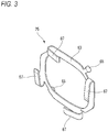
- Fig. 3 is a perspective view of the plate spring member 25 shown in Fig. 1 .
- the plate spring member 25 made of metal is accommodated in the tube bottom 49 of the hood 21.
- the plate spring member 25 includes a plate spring main body portion 63.
- the plate spring member 25 is formed in a square frame shape obtained by punching a metal plate parallel to the tube bottom 49 into a substantially rectangular shape.
- a pair of press-fitting projections 65 protrude from a surface of the plate spring main body portion 63 facing the tube bottom 49 so as to correspond to the press-fitting holes 61.
- Four spring portions 67 are integrally formed on a surface of the plate spring main body portion 63 on a side not facing the tube bottom 49.
- the spring portions 67 are formed by bending so as to overlap along sides of the plate spring main body portion 63, respectively.
- Each of the spring portions 67 is formed as a plate spring with a bent tip end as a free end.
- Fig. 4 is a perspective view of the backlash regulating member 27 shown in Fig. 1 .
- the backlash regulating member 27 is formed of an insulating resin material.
- the backlash regulating member 27 is formed in a square frame shape substantially similar to the plate spring main body portion 63.
- the backlash regulating member 27 is mounted on an opposite side of the tube bottom 49 across the plate spring member 25.
- the backlash regulating member 27 is urged in a direction opposite to a fitting direction (Z direction) of the mating hood 23 by the spring portions 67 of the plate spring member 25.
- protruding portions 69 protruding in extending directions of the side portions thereof are formed.
- the protruding portions 69 are respectively locked to the locked protruding portions 59 provided in the grooves 57 described above.
- the backlash regulating member 27 is movable along a fitting direction (Z direction) of the mating hood 23, and is regulated from falling-off from the hood 21 of the connector 13.
- a pair of displacement preventing projections 71 protrude an upper side portion and a lower side portion from a surface of the backlash regulating member 27 facing the tube bottom 49.
- the spring portion 67 is displaced by a constant amount, a protruding tip end of the displacement preventing projection 71 abuts against the tube bottom 49.
- Figs. 5A and 5B are plan sectional views of the connector 13 shown in Fig. 1 .
- Fig. 5A is a plan sectional view of the hood 21 to which the plate spring member 25 is mounted.
- Fig. 5B is a plan sectional view of the hood 21 to which the plate spring member 25 and the backlash regulating member 27 are mounted.
- the plate spring member 25 is inserted into the fitting space 55 of the hood 21, and the press-fitting projections 65 are respectively press-fitted into the press-fitting holes 61, so that the plate spring main body portion 63 is fixed in close contact with the tube bottom 49 in parallel.
- the backlash regulating member 27 is inserted into the fitting space 55 in the hood 21 in which the plate spring member 25 is fixed to the tube bottom 49.
- the protruding portions 69 are respectively engaged with the locked protruding portions 59 of the grooves 57, the backlash regulating member 27 is regulated from falling-off from the hood 21, and the mounting is completed.
- the spring portion 67 is in a state of being bent by a predetermined amount in advance in an arrow direction shown in Fig. 5B .
- Fig. 6 is a front view of the mating connector 15 shown in Fig. 1 .
- the mating hood 23 fitted inside the hood 21 is integrally formed with the mating housing 41 of the mating connector 15.
- the inner tube portion 53 of the connector 13 is fitted inside the mating hood 23.
- the pair of mating terminals 19 that enter the terminal receiving ports 51 protrude inside the mating hood 23.
- the ribs 73 are inserted into the grooves 57 of the hood 21 and serve as a fitting guide, respectively.
- a mating hood tip end surface 29 is formed at a tip end of the mating hood 23 in the fitting direction (Z direction). Immediately before the completion of the fitting, the mating hood tip end surface 29 abuts against the backlash regulating member 27.
- a regulating member abutting surface 31 (see Fig. 4 ) pressed by the mating hood tip end surface 29 is formed in the backlash regulating member 27 in a fitting state between the housing 39 and the mating housing 41.
- the packing 33 is accommodated in the fitting space 55 of the hood 21.
- the packing 33 is formed in an annular shape by rubber or the like.
- the packing 33 is mounted on an outer periphery of the inner tube portion 53 to seal the inner tube portion 53 and the mating hood 23 in a watertight manner.
- the electric wires 37 are respectively electrically connected to the terminals 17 by crimping or the like.
- the annular rubber plugs 35 are mounted to outer peripheries of the electric wires 37 connected to the terminals 17, respectively.
- the rubber plug 35 seals between an electric wire outlet port 74 (see Fig. 8 ) of the housing 39 from which the electric wire 37 is led out and the electric wire 37.
- the rubber plug 35 is fixed to the electric wire 37 by, for example, being crimped to a crimping piece of the terminal 17.
- the lock arm 43 of the connector 13 is formed in a cantilever shape in which a base end thereof is formed integrally with the housing 39 and the other end thereof extending forward is a free end.
- the lock arm 43 has an operation arm 44 extending rearward from a free end side. A rear end side of the operation arm 44 serves as an operation portion.
- the lock arm 43 includes an arm tip end portion 75 that faces the mating hood 23 of the mating connector 15. The arm tip end portion 75 is engaged with the lock projection 47 formed on the mating hood 23.
- the lock arm 43 and the lock projection 47 form a lock mechanism that fits and locks the connector 13 and the mating connector 15.
- the side spacer 45 is inserted into a terminal accommodating chamber from one side surface of the housing 39. By inserting a regulating portion 46 into the terminal accommodating chamber, the side spacer 45 locks a rear end of the terminal 17 to regulate the terminal 17 from coming-off.
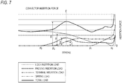
- Fig. 7 is a graph showing a correlation between a stroke and an insertion force when the high vibration resistant connector 11 shown in Fig. 1 is fitted.
- a vertical axis of the graph represents the insertion force.
- a dotted line in the graph represents a lock insertion load, a broken line represents a packing insertion load, a chain line represents a terminal insertion load, a two-dot chain line represents a spring load, and a solid line represents a total load.
- Fig. 8 is a longitudinal sectional view of the high vibration resistant connector 11 in which contact between the lock arm 43 and the lock projection 47 is started.
- Fig. 9 is a longitudinal sectional view of the high vibration resistant connector 11 in which the packing 33 is started to be contacted.
- Fig. 10 is a longitudinal sectional view of the high vibration resistant connector 11 in which contact between the terminal 17 and the mating terminal 19 is started.
- Fig. 11 is a longitudinal sectional view of the high vibration resistant connector 11 in which contact between the mating hood 23 and the backlash regulating member 27 is started.
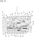
- Fig. 12 is a longitudinal sectional view of the high vibration resistant connector 11 that has been fitted
- Fig. 13 is an enlarged view of a main part of Fig. 12 .
- an abutting start position of the mating hood tip end surface 29 (see Fig. 6 ) and the regulating member abutting surface 31 is set to the predetermined stroke position P1 after a fitting force of the housing 39 and the mating housing 41 reaches the maximum (after the stroke position E).
- the lock projection 47 and the lock arm 43 are engaged with each other in the fitted state of the high vibration resistant connector 11, and an abutting state between the mating hood tip end surface 29 and the regulating member abutting surface 31 of the backlash regulating member 27 is maintained.
- the connector 13 and the mating connector 15 are fitted and locked by the lock mechanism configured by the lock arm 43 and the lock projection 47, so that the fitting therebetween is regulated from being released.
- the connector structure according to the first embodiment is in a locked state in which the release of the fitting is regulated during use.
- the lock arm 43 is provided on the connector 13
- the lock projection 47 is provided on the mating connector 15, for example.
- Either of the lock arm 43 or the lock projection 47 configuring the lock mechanism may be provided on the connector 13 or the mating connector 15 as long as the lock arm 43 and the lock projection 47 relatively approach each other at the time of fitting.
- the lock arm 43 provided in the connector 13 has the arm side locking surface 79 perpendicular to the fitting direction in a direction opposite to the fitting direction of the mating connector 15. Since the arm side locking surface 79 is disposed on the free end side of the lock arm 43, the arm side locking surface 79 can be displaced in a direction substantially perpendicular to the fitting direction of the mating connector 15.
- the lock projection 47 of the mating connector 15 is provided with the arm push-up inclined surface 77 having a downward slope that gradually decreases in the fitting direction (Z direction). That is, the arm push-up inclined surface 77 is an inclined surface gradually increasing toward the direction opposite side to the fitting direction (Z direction).
- the arm push-up inclined surface 77 is formed with the mating locking surface 81 that hangs substantially vertically at a top portion of a terminal end thereof that gradually increases.
- the lock arm 43 and the lock projection 47 approach each other.
- the arm push-up inclined surface 77 formed on the lock projection 47 abuts against the arm tip end portion 75 on which the arm side locking surface 79 is formed.
- the arm tip end portion 75 is pushed up by the arm push-up inclined surface 77. That is, the arm tip end portion 75 goes up the arm push-up inclined surface 77.
- the arm tip end portion 75 reaches the top portion of the arm push-up inclined surface 77. In this state, the lock arm 43 is elastically deformed to the uppermost position.
- the arm tip end portion 75 needs to pass through the top portion of the arm push-up inclined surface 77.
- the lock arm 43 finishes riding on the arm push-up inclined surface 77.
- the lock arm 43 falls along the mating locking surface 81 by an elastic restoring force. Accordingly, the mating locking surface 81 and the arm side locking surface 79 face each other, and the connector 13 and the mating connector 15 is regulated from being detached. That is, the connector 13 and the mating connector 15 are locked in the fitted state by the lock mechanism.
- the arm tip end portion 75 must slightly pass through the top portion so as to fall along the mating locking surface 81.
- a slight passing distance is an essential clearance for completing the locking of the lock mechanism.
- the clearance in the lock mechanism remains even when the connector 13 and the mating connector 15 are in the locked state. That is, even in the fitted and locked state of the connector, the lock arm 43 and the lock projection 47 can move slightly relative to each other by the clearance.
- the terminal 17 accommodated in the housing 39 and the mating terminal 19 accommodated in the mating housing 41 can be finely slid by the clearance due to vibration during traveling of a vehicle or the like.
- wear that is, fine sliding wear
- an electrical connection reliability may be reduced.
- the plate spring member 25 made of metal is provided at the tube bottom 49 of the hood 21.
- the backlash regulating member 27 is provided on an opposite side of the tube bottom 49 across the plate spring member 25.
- the backlash regulating member 27 is urged by the plate spring member 25 in the direction opposite to the fitting direction (Z direction) of the mating hood 23.
- the backlash regulating member 27 is provided with the regulating member abutting surface 31.
- the regulating member abutting surface 31 is pressed by the mating hood tip end surface 29 formed at the tip end of the mating hood 23 in the fitting direction.
- the backlash regulating member 27 including the regulating member abutting surface 31 pressed by the mating hood tip end surface 29 compresses and deforms the spring portion 67 of the plate spring member 25 against a spring force (elastic restoring force).
- the arm tip end portion 75 that has reached the top portion of the arm push-up inclined surface 77 passes through the top portion by the clearance and locks the arm side locking surface 79 to the mating locking surface 81. Even in movement by the clearance, the plate spring member 25 is compressed to accumulate the elastic restoring force. Therefore, when an insertion force for the fitting is released, the mating housing 41 of the mating connector 15 is urged by the elastic restoring force of the plate spring member 25 and pushed back in the direction opposite to the fitting direction.
- the mating locking surface 81 of the lock projection 47 provided on the mating housing 41 is brought into close contact with the arm side locking surface 79 of the lock arm 43 provided on the housing 39, and the clearance in the lock mechanism can be eliminated. That is, the backlash by the clearance in the lock mechanism that fits and locks the housing 39 and the mating housing 41 is reduced. Accordingly, in the connector structure according to the first embodiment, in the fitted and locked state of the housing 39 and the mating housing 41, a movement between the mating locking surface 81 of the lock projection 47 and the arm side locking surface 79 of the lock arm 43 in an approaching/separating direction becomes impossible due to the clearance in the lock mechanism. As a result, in the connector structure according to the first embodiment, even when the vibration occurs when the vehicle is traveling or the like, the fine sliding between the terminal 17 accommodated in the housing 39 and the mating terminal 19 accommodated in the mating housing 41 can be suppressed.
- the plate spring member 25 that pushes back the mating housing 41 so as to eliminate the clearance in the lock mechanism is made of a metal elastic member. Therefore, the plate spring member 25 is less likely to creep due to aging such as an elastic member made of rubber or resin. That is, a push-back force acting on the mating housing 41 can be maintained for a long period of time. Therefore, the plate spring member 25 can maintain the elastic repulsive force of the spring portion 67 even in long-term use, and can suppress the backlash in the fitting direction between the housing 39 and the mating housing 41.
- abrasion powder generated by the fine sliding wear between the terminal 17 and the mating terminal 19 can be suppressed from being an oxide insulator, so that a contact reliability between the terminal 17 and the mating terminal 19 can be suppressed from being reduced. Therefore, it is possible to maintain a good contact reliability over a long period of time.
- the fitting space 55 is effectively used by accommodating the plate spring member 25 and the backlash regulating member 27 in the fitting space 55 of the hood 21 into which the mating hood 23 is inserted. As a result, it is not necessary to ensure a dedicated backlash regulating space in other portions.
- the backlash regulating member 27 includes the displacement preventing projection 71 protruding toward the tube bottom 49.
- the backlash regulating member 27 presses the plate spring member 25 toward the tube bottom 49 when the regulating member abutting surface 31 is pressed by the mating hood tip end surface 29.
- the spring portion 67 provided on the plate spring member 25 is compressed and deformed by this pressing.
- the displacement preventing projection 71 abuts against the tube bottom 49 before displacement exceeding the elastic limit is applied.
- the spring portion 67 of the plate spring member 25 can be prevented from being excessively deformed beyond the elastic limit and plastically deformed, so that a stable backlash reducing action can be maintained.
- the mating hood tip end surface 29 and the regulating member abutting surface 31 are abutted after the fitting force of the housing 39 and the mating housing 41 reaches the maximum. That is, in the fitting process of the housing 39 and the mating housing 41, the lock arm 43 first comes into contact with the lock projection 47 of the mating housing 41 in the lock mechanism, and the lock insertion load starts to occur. Next, the mating hood 23 and the packing 33 come into contact with each other, and the packing insertion load starts to occur. Then, the mating terminal 19 and the terminal 17 come into contact with each other, and the terminal insertion load starts to occur. As a result, all three of the lock insertion load, the packing insertion load, and the terminal insertion load, which are elements of the connector insertion force, are generated.
- the connector insertion force D is maximized in this state.
- the connector structure according to the first embodiment after the connector insertion force D reaches the maximum (after the stroke position E), the abutting of the mating hood tip end surface 29 and the regulating member abutting surface 31 is started. Accordingly, the spring load of the spring portion 67 of the plate spring member 25 starts to occur.
- the spring load is generated (the predetermined stroke position PI)
- a time point when the connector insertion force becomes maximum has passed. That is, only the respective static loads are generated.
- the connector structure according to the first embodiment is configured such that generation of the spring load does not increase the connector insertion force D.
- Fig. 14 is a perspective view of a mating connector 83 in a high vibration resistant connector including a connector structure according to the second embodiment of the present invention.
- insertion portions 85 are formed on the mating hood tip end surface 29 of the mating connector 83.
- Each of the insertion portions 85 is formed of a wedge-shaped tapered surface that gradually becomes thinner toward the tip end.
- An angle of the wedge-shaped tapered surface of the insertion portion 85 is set at ⁇ 1 (see Fig. 16 ).
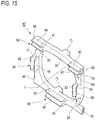
- Fig. 15 is a perspective view of a backlash regulating member 87 according to the second embodiment of the present invention.
- the regulating member abutting surface 31 of the backlash regulating member 87 is provided with backlash regulating protruding portions 89.
- a V-shaped groove 91 is formed on each of the backlash regulating protruding portions 89 by an inner side bending piece 93 bent toward the inside of the tube of the hood 21 and an outer side bending piece 95 bent toward the outside of the tube of the hood 21.
- the V-shaped groove 91 of the backlash regulating protruding portion 89 is pressed by the insertion portion 85.
- At least one backlash regulating protruding portion 89 is provided on the regulating member abutting surface 31 in an upper-lower direction (Y direction) and a left-right direction (X direction) that are respectively orthogonal to the tubular center axis L of the hood 21, and are orthogonal to each other.
- Fig. 16 is an enlarged view of a main part showing an angle of the insertion portion 85 formed on the mating hood tip end surface 29 and an angle of the V-shaped groove 91 in the high vibration resistant connector according to the second embodiment of the present invention.
- the V-shaped groove 91 gradually approaches a groove inner wall on both sides toward a groove bottom.
- An interior angle of the V-shaped groove 91 is set to ⁇ 2.
- the interior angle ⁇ 2 of the V-shaped groove 91 and the taper angle ⁇ 1 of the insertion portion 85 are set in a relationship of ⁇ 1 > ⁇ 2.
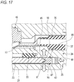
- Fig. 17 is an operation explanatory view showing a backlash reducing action by the insertion portion 85 and the V-shaped groove 91 in the high vibration resistant connector according to the second embodiment of the present invention.
- the insertion portion 85 formed on the mating hood tip end surface 29 is inserted into the V-shaped groove 91 of the backlash regulating protruding portion 89.
- the spring portion 67 of the plate spring member 25 is pressed and elastically deformed by the backlash regulating member 87, and the elastic restoring force is generated in the spring portion 67 of the plate spring member 25.
- the pointed wedge-shaped insertion portion 85 bends and deforms the inner side bending piece 93 and the outer side bending piece 95 of the backlash regulating protruding portion 89 configuring the V-shaped groove 91, respectively.
- At least four backlash regulating protruding portions 89 provided on the regulating member abutting surface 31 are provided on upper and lower sides of the regulating member abutting surface 31 that sandwich the tubular center axis L of the hood 21 vertically and left and right sides of the regulating member abutting surface 31 that sandwich the tubular center axis L of the hood 21 on the left and right.
- a pair of the backlash regulating protruding portions 89 according to the second embodiment is provided on one of the four sides (upper side of the regulating member abutting surface 31) with the tubular center axis L interposed therebetween. Therefore, a total of five backlash regulating protruding portions 89 are provided.
- the five backlash regulating protruding portions 89 provided on the regulating member abutting surface 31 are arranged radially in four directions sandwiching the tubular center axis L in the upper-lower and left-right directions (Y, X directions).
- the mating hood tip end surface 29 of the mating connector 83 abuts against the backlash regulating member 87 substantially uniformly in a radial direction (upper-lower and left-right directions) around the tubular center axis L. Accordingly, an urging force of the plate spring member 25 acting on the mating hood tip end surface 29 via the backlash regulating member 87 is substantially uniform in the radial direction around the tubular center axis L.
- the backlash regulating member 87 can maintain a high degree of parallelism with the tube bottom 49 of the connector 13 even when the plate spring member 25 is pressed or moved or when the mating hood 23 of the mating connector 83 is pushed back. Therefore, in the connector structure according to the second embodiment, it is possible to prevent the backlash regulating member 87 from being inclined with respect to the tube bottom 49 and causing the backlash reducing action to be uneven in the radial direction.
- the present invention is not limited to the embodiments described above, and may be appropriately modified, improved or the like.
- the material, shape, size, number, arrangement position, or the like of each component in the above-described embodiments are optional and are not limited as long as the present invention can be achieved.
Landscapes
- Details Of Connecting Devices For Male And Female Coupling (AREA)
- Connector Housings Or Holding Contact Members (AREA)
- Coupling Device And Connection With Printed Circuit (AREA)
Abstract
Description
- The present invention relates to a connector structure.
- There has been known a technique for providing a connector structure without rattle (for example, Patent Literature 1). As shown in
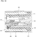
Fig. 18 , the connector structure includes aconnector 503 including ahood 501 and amating connector 507 including amating hood 505. In themating connector 507, apacking 509 that is an elastic member made of a resin is disposed inside themating hood 505. In a fitting state of both connectors, thehood 501 of theconnector 503 is inserted into themating hood 505 of themating connector 507, and a tip end of thehood 501 presses aprotruding piece 511 of thepacking 509 to suppress a backlash between theconnector 503 and themating connector 507 in a fitting axial direction.
[Patent Literature 1]JP-A-2005-174813 - In the conventional connector structure, the
packing 509 is accommodated in a fitting space of themating hood 505, and thehood 501 is also inserted into the fitting space, so that the fitting space is effectively used. - However, since the
packing 509 is the elastic member made of the resin, there is a concern that an elastic repulsive force is reduced due to deterioration due to long-term use, and an effect of suppressing the backlash is reduced. As a result, due to vibration during traveling of a vehicle or the like, an electrical connection reliability may be reduced due to fine sliding wear between amale tab 513 and acontact spring 515 of a female terminal. - One or more embodiments provide a connector structure capable of obtaining a stable vibration resistant effect even after aging.
- In an aspect (1), one or more embodiments provide a connector structure including a bottomed tubular hood formed in a housing, a mating hood formed in a mating housing and fitted inside the hood, a plate spring member made of metal accommodated in a tube bottom of the hood, a backlash regulating member provided on an opposite side of the tube bottom across the plate spring member and urged in a direction opposite to a fitting direction of the mating hood by the plate spring member, a mating hood tip end surface formed at a tip end of the mating hood in the fitting direction, and a regulating member abutting surface provided on the backlash regulating member and pressed by the mating hood tip end surface in a fitted state that the housing and the mating housing are fitted.
- According to the aspect (1), the plate spring member made of metal is provided at the tube bottom of the hood. The backlash regulating member is provided on an opposite side of the tube bottom across the plate spring member. The backlash regulating member is urged in a direction opposite to a fitting direction of the mating hood by the plate spring member. The backlash regulating member is provided with the regulating member abutting surface. Immediately before completion of fitting, the regulating member abutting surface is pressed by the mating hood tip end surface formed at a tip end of the mating hood in the fitting direction. The backlash regulating member including the regulating member abutting surface pressed by the mating hood tip end surface compresses and deforms the plate spring member against a spring force (elastic restoring force). When an insertion force for the fitting is released, the mating housing is urged by the elastic restoring force of the plate spring member and pushed back in the direction opposite to the fitting direction.
- Therefore, in the mating housing pushed back by the elastic restoring force of the plate spring member, a mating locking surface of a lock projection provided on the mating housing is came into close contact with an arm side locking surface of a lock arm provided on the housing, and a clearance in a lock mechanism can be eliminated. That is, the backlash by the clearance in the lock mechanism that fits and locks both of the housings is reduced. Accordingly, in the connector structure according to the present configuration, in the fitted and locked state of the both housings, a movement of the mating locking surface of the lock projection and the arm side locking surface of the lock arm in an approaching/separating direction due to the clearance in the lock mechanism becomes impossible. As a result, in the connector structure according to the present configuration, even when vibration occurs when the vehicle is traveling or the like, fine sliding between a terminal accommodated in the housing and a mating terminal accommodated in the mating housing can be suppressed. In the connector structure according to the present configuration, the plate spring member that pushes back the mating housing so as to eliminate the clearance in the lock mechanism is made of a metal elastic member. Therefore, the plate spring member is less likely to creep due to aging such as an elastic member made of rubber or resin. That is, a push-back force acting on the mating housing can be maintained for a long period of time. Therefore, the plate spring member can maintain an elastic repulsive force of the spring portion even in long-term use, and can suppress the backlash in the fitting direction between the housing and the mating housing. Therefore, according to the connector structure of the present configuration, abrasion powder generated by the fine sliding wear between the terminal and the mating terminal can be suppressed from being an oxide insulator, so that a contact reliability between the terminal and the mating terminal can be suppressed from being reduced. Therefore, it is possible to maintain a good contact reliability over a long period of time.
- In an aspect (2), the connector structure may further include an insertion portion formed on the mating hood tip end surface, and a backlash regulating protruding portion provided on the regulating member abutting surface and including a V-shaped groove formed by an inner side bending piece bent toward an inside of a tube of the hood and an outer side bending piece bent to an outside of the tube of the hood. The V-shaped groove of the backlash regulating protruding portion is pressed by the insertion portion.
- According to the aspect (2), in the fitting process of the housing and the mating housing, the insertion portion formed on the mating hood tip end surface is inserted into the V-shaped groove of the backlash regulating protruding portion. When further inserted, the spring portion of the plate spring member is pressed and elastically deformed by the backlash regulating member, and the elastic restoring force is generated in the spring portion of the plate spring member. Then, due to the urging of the elastic restoring force of the spring portion, the insertion portion bends and deforms the inner side bending piece and the outer side bending piece of the backlash regulating protruding portion configuring the V-shaped groove, respectively.
- Therefore, in the fitted state of the housing and the mating housing, the lock projection and the lock arm in the lock mechanism are engaged, and the insertion portion maintains the inner side bending piece and the outer side bending piece of the backlash regulating protruding portion in a bent state. As a result, due to the bending of the inner side bending piece and the outer side bending piece provided in the backlash regulating protruding portion of the backlash regulating member, backlash due to clearance in a direction orthogonal to a housing fitting direction between the housing and the mating housing is suppressed. Therefore, in the fitted state of the housing and the mating housing, even if the vibration is applied to the vehicle, the fine sliding wear due to the terminal and the mating terminal is suppressed, and an electrical connection reliability is improved.
- In an aspect (3), at least one backlash regulating protruding portion may be provided on each of the regulating member abutting surfaces in an upper-lower direction and a left-right direction which are orthogonal to a tubular center axis of the hood and orthogonal to each other.
- According to the aspect (3), at least four backlash regulating protruding portions provided on the regulating member abutting surface are provided on upper and lower sides of the regulating member abutting surface that sandwich the tubular center axis of the hood vertically and left and right sides of the regulating member abutting surface that sandwich the tubular center axis of the hood on the left and right. Incidentally, a pair of the backlash regulating protruding portions may be provided on one of the four sides (for example, an upper side of the regulating member abutting surface) with the tubular center axis interposed therebetween. In this case, a total of five backlash regulating protruding portions are provided. As described above, in the connector structure according to the present configuration, the backlash regulating protruding portions provided on the regulating member abutting surface are arranged radially in four directions sandwiching the tubular center axis in the upper-lower and left-right directions. Therefore, the mating hood tip end surface abuts against the backlash regulating member substantially uniformly in a radial direction around the tubular center axis. As a result, an urging force of the plate spring member acting on the mating hood tip end surface via the backlash regulating member is substantially uniform in the radial direction around the tubular center axis. As a result, the backlash regulating member can maintain a high degree of parallelism with the tube bottom even when the plate spring member is pressed and moved or when the mating hood is pushed back. Therefore, in the connector structure according to the present configuration, it is possible to prevent the backlash regulating member from being inclined with respect to the tube bottom and causing the backlash reducing action to be uneven in the radial direction.
- In an aspect (4), the backlash regulating member may be provided with a displacement preventing projection abutting against the tube bottom. The displacement preventing projection may be configured to prevent from an excessive displacement of the plate spring member.
- According to the aspect (4), the backlash regulating member includes the displacement preventing projection protruding toward the tube bottom. When the connector and the mating connector are fitted, the backlash regulating member presses the plate spring member toward the tube bottom when the regulating member abutting surface is pressed by the mating hood tip end surface. The spring portion provided on the plate spring member is compressed and deformed by this pressing. In a process of compressing and deforming the spring portion of the plate spring member, the displacement preventing projection abuts against the tube bottom before displacement exceeding an elastic limit is applied. Accordingly, further displacement of the spring portion of the plate spring member is regulated. As a result, in the connector structure according to the present configuration, the spring portion of the plate spring member can be prevented from being excessively deformed beyond the elastic limit and plastically deformed, so that a stable backlash reducing action can be maintained.
- In an aspect (5), an abutting start position of the mating hood tip end surface and the regulating member abutting surface may be set to a predetermined stroke position, so that the mating hood tip end surface and the regulating member abutting surface are abutted after a fitting force of the housing and the mating housing reaches a maximum.
- According to the aspect (5), the abutting of the mating hood tip end surface and the regulating member abutting surface starts after the fitting force of the housing and the mating housing reaches the maximum. That is, in the fitting process of the housing and the mating housing, the lock arm first comes into contact with the lock projection of the mating housing in the lock mechanism, and a lock insertion load starts to occur, for example. Next, the mating hood and the packing come into contact with each other, and a packing insertion load starts to occur. Then, the mating terminal and the terminal come into contact with each other, and a terminal insertion load starts to occur. As a result, all three of the lock insertion load, the packing insertion load, and the terminal insertion load, which are elements of the connector insertion force, are generated.
- In the connector structure according to the present configuration, the connector insertion force is maximized in this state. In the connector structure according to the present configuration, after the connector insertion force reaches the maximum, the abutting of the mating hood tip end surface and the regulating member abutting surface is started. As a result, the spring load of the spring portion of the plate spring member starts to occur. However, when the spring load is generated, a time point when the connector insertion force becomes maximum has passed. That is, only the respective static loads are generated. Therefore, the connector structure according to the present configuration is configured such that the generation of the spring load does not increase the connector insertion force.
- According to one or more embodiments, a stable vibration resistant effect can be obtained even after aging.
- The present invention has been briefly described above. Further, details of the present invention will be clarified by reading a mode for carrying out the invention to be described below with reference to accompanying drawings.
-
-
Fig. 1 is an exploded perspective view of a high vibration resistant connector including a connector structure according to a first embodiment. -
Fig. 2 is a front view of the connector shown inFig. 1 . -
Fig. 3 is a perspective view of a plate spring member shown inFig. 1 . -
Fig. 4 is a perspective view of a backlash regulating member shown inFig. 1 . -
Fig. 5A and 5B are plan sectional views of the connector shown inFig. 1 .Fig. 5A is a plan sectional view of a hood to which the plate spring member is mounted.Fig. 5B is a plan sectional view of the hood to which the plate spring member and the backlash regulating member are mounted. -
Fig. 6 is a front view of a mating connector shown inFig. 1 . -
Fig. 7 is a graph showing a correlation between a stroke and an insertion force when the high vibration resistant connector shown inFig. 1 is fitted. -
Fig. 8 is a longitudinal sectional view of the high vibration resistant connector in which contact between a lock arm and a lock projection is started. -
Fig. 9 is a longitudinal sectional view of the high vibration resistant connector in which the packing is started to be contacted. -
Fig. 10 is a longitudinal sectional view of the high vibration resistant connector in which contact between a terminal and a mating terminal is started. -
Fig. 11 is a longitudinal sectional view of the high vibration resistant connector in which contact between a mating hood and the backlash regulating member is started. -
Fig. 12 is a longitudinal sectional view of the high vibration resistant connector that has been fitted. -
Fig. 13 is an enlarged view of a main part ofFig. 12 . -
Fig. 14 is a perspective view of a mating connector in a high vibration resistant connector including a connector structure according to a second embodiment of the present invention. -
Fig. 15 is a perspective view of a backlash regulating member according to the second embodiment of the present invention. -
Fig. 16 is an enlarged view of a main part showing an angle of an insertion portion formed on a mating hood tip end surface and an angle of a V-shaped groove in the high vibration resistant connector according to the second embodiment of the present invention. -
Fig. 17 is an operation explanatory view showing a backlash reducing action by the insertion portion and the V-shaped groove in the high vibration resistant connector according to the second embodiment of the present invention. -
Fig. 18 is a longitudinal sectional view of a connector having a conventional connector structure. - Embodiments of the present invention will be described below with reference to the drawings.
-
Fig. 1 is an exploded perspective view of a high vibrationresistant connector 11 including a connector structure according to a first embodiment of the present invention. In the present specification, X, Y and Z directions follow directions of arrows shown inFig. 1 . - The connector structure according to the first embodiment is applied to the high vibration
resistant connector 11. - The high vibration
resistant connector 11 is configured to fit aconnector 13 and amating connector 15. In the first embodiment, theconnector 13 is a female connector. Themating connector 15 is a male connector. Themating connector 15 can be formed as a part of an auxiliary machine, for example. Theconnector 13 accommodates, for example, twofemale terminals 17 formed in a box shape. Themating connector 15 accommodates, for example, two male mating terminals 19 (seeFig. 8 ) formed in a tab shape. Incidentally, a shape and the number of the terminals of the connector structure are not limited thereto. - The connector structure according to the first embodiment mainly includes a
hood 21 of theconnector 13, amating hood 23 of amating connector 15, aplate spring member 25, abacklash regulating member 27, a mating hood tip end surface 29 (seeFig. 6 ) of themating connector 15, and a regulatingmember abutting surface 31 of thebacklash regulating member 27. - In addition, the connector structure according to the first embodiment includes a packing 33, rubber plugs 35,
electric wires 37, ahousing 39 of theconnector 13, amating housing 41 of themating connector 15, alock arm 43, aside spacer 45, and alock projection 47. -
Fig. 2 is a front view of theconnector 13 shown inFig. 1 . - The
hood 21 of theconnector 13 is formed integrally with thehousing 39 made of an insulating resin, and is formed in a substantially rectangular bottomed tubular shape. Atube bottom 49 is a back wall of thehousing 39. Aninner tube portion 53 formed with terminal receivingports 51 protrudes coaxially inside thehood 21. An annularfitting space 55 is formed between theinner tube portion 53 and thehood 21. Themating hood 23 of themating connector 15 is fitted into thefitting space 55. In thefitting space 55,grooves 57 extending along a tubular center axis L are formed above and below theinner tube portion 53 so as to sandwich theinner tube portion 53. Each of thegrooves 57 is provided with a locked protruding portion 59 (seeFigs. 5A and 5B ). A pair of press-fittingholes 61 are formed on both sides of a line segment connecting a pair of diagonal corners of thetube bottom 49 of thefitting space 55. -
Fig. 3 is a perspective view of theplate spring member 25 shown inFig. 1 . Theplate spring member 25 made of metal is accommodated in thetube bottom 49 of thehood 21. Theplate spring member 25 includes a plate springmain body portion 63. Theplate spring member 25 is formed in a square frame shape obtained by punching a metal plate parallel to the tube bottom 49 into a substantially rectangular shape. A pair of press-fittingprojections 65 protrude from a surface of the plate springmain body portion 63 facing the tube bottom 49 so as to correspond to the press-fittingholes 61. Fourspring portions 67 are integrally formed on a surface of the plate springmain body portion 63 on a side not facing thetube bottom 49. Thespring portions 67 are formed by bending so as to overlap along sides of the plate springmain body portion 63, respectively. Each of thespring portions 67 is formed as a plate spring with a bent tip end as a free end. -
Fig. 4 is a perspective view of thebacklash regulating member 27 shown inFig. 1 . - The
backlash regulating member 27 is formed of an insulating resin material. Thebacklash regulating member 27 is formed in a square frame shape substantially similar to the plate springmain body portion 63. Thebacklash regulating member 27 is mounted on an opposite side of the tube bottom 49 across theplate spring member 25. Thebacklash regulating member 27 is urged in a direction opposite to a fitting direction (Z direction) of themating hood 23 by thespring portions 67 of theplate spring member 25. On both sides of an upper side portion and both sides of a lower side portion of thebacklash regulating member 27, protrudingportions 69 protruding in extending directions of the side portions thereof are formed. The protrudingportions 69 are respectively locked to the locked protrudingportions 59 provided in thegrooves 57 described above. As a result, thebacklash regulating member 27 is movable along a fitting direction (Z direction) of themating hood 23, and is regulated from falling-off from thehood 21 of theconnector 13. - A pair of
displacement preventing projections 71 protrude an upper side portion and a lower side portion from a surface of thebacklash regulating member 27 facing thetube bottom 49. When thespring portion 67 is displaced by a constant amount, a protruding tip end of thedisplacement preventing projection 71 abuts against thetube bottom 49. -
Figs. 5A and 5B are plan sectional views of theconnector 13 shown inFig. 1 .Fig. 5A is a plan sectional view of thehood 21 to which theplate spring member 25 is mounted.Fig. 5B is a plan sectional view of thehood 21 to which theplate spring member 25 and thebacklash regulating member 27 are mounted. - As shown in
Fig. 5A , theplate spring member 25 is inserted into thefitting space 55 of thehood 21, and the press-fittingprojections 65 are respectively press-fitted into the press-fittingholes 61, so that the plate springmain body portion 63 is fixed in close contact with the tube bottom 49 in parallel. - As shown in
Fig. 5B , thebacklash regulating member 27 is inserted into thefitting space 55 in thehood 21 in which theplate spring member 25 is fixed to thetube bottom 49. When the protrudingportions 69 are respectively engaged with the locked protrudingportions 59 of thegrooves 57, thebacklash regulating member 27 is regulated from falling-off from thehood 21, and the mounting is completed. In this engaged state, thespring portion 67 is in a state of being bent by a predetermined amount in advance in an arrow direction shown inFig. 5B . - When the
spring portion 67 is deformed by the predetermined amount in a mounting completed state of thebacklash regulating member 27 shown inFig. 5B , thedisplacement preventing projection 71 provided in thebacklash regulating member 27 abuts against thetube bottom 49. As a result, thedisplacement preventing projection 71 prevents thespring portion 67 from being deformed excessively beyond an elastic limit and plastically deformed. -
Fig. 6 is a front view of themating connector 15 shown inFig. 1 . - The
mating hood 23 fitted inside thehood 21 is integrally formed with themating housing 41 of themating connector 15. Theinner tube portion 53 of theconnector 13 is fitted inside themating hood 23. The pair ofmating terminals 19 that enter theterminal receiving ports 51 protrude inside themating hood 23. On both sides of an upper side portion and both sides of a lower side portion of themating hood 23,ribs 73 protruding in extending directions of the side portions thereof are formed. Theribs 73 are inserted into thegrooves 57 of thehood 21 and serve as a fitting guide, respectively. A mating hoodtip end surface 29 is formed at a tip end of themating hood 23 in the fitting direction (Z direction). Immediately before the completion of the fitting, the mating hoodtip end surface 29 abuts against thebacklash regulating member 27. - A regulating member abutting surface 31 (see
Fig. 4 ) pressed by the mating hoodtip end surface 29 is formed in thebacklash regulating member 27 in a fitting state between thehousing 39 and themating housing 41. - The packing 33 is accommodated in the
fitting space 55 of thehood 21. The packing 33 is formed in an annular shape by rubber or the like. The packing 33 is mounted on an outer periphery of theinner tube portion 53 to seal theinner tube portion 53 and themating hood 23 in a watertight manner. - The
electric wires 37 are respectively electrically connected to theterminals 17 by crimping or the like. The annular rubber plugs 35 are mounted to outer peripheries of theelectric wires 37 connected to theterminals 17, respectively. The rubber plug 35 seals between an electric wire outlet port 74 (seeFig. 8 ) of thehousing 39 from which theelectric wire 37 is led out and theelectric wire 37. Therubber plug 35 is fixed to theelectric wire 37 by, for example, being crimped to a crimping piece of the terminal 17. - The
lock arm 43 of theconnector 13 is formed in a cantilever shape in which a base end thereof is formed integrally with thehousing 39 and the other end thereof extending forward is a free end. Thelock arm 43 has anoperation arm 44 extending rearward from a free end side. A rear end side of theoperation arm 44 serves as an operation portion. Thelock arm 43 includes an armtip end portion 75 that faces themating hood 23 of themating connector 15. The armtip end portion 75 is engaged with thelock projection 47 formed on themating hood 23. Thelock arm 43 and thelock projection 47 form a lock mechanism that fits and locks theconnector 13 and themating connector 15. - The
side spacer 45 is inserted into a terminal accommodating chamber from one side surface of thehousing 39. By inserting a regulatingportion 46 into the terminal accommodating chamber, theside spacer 45 locks a rear end of the terminal 17 to regulate the terminal 17 from coming-off. - Next, a fitting operation of the connector structure according to the first embodiment will be described.
-
Fig. 7 is a graph showing a correlation between a stroke and an insertion force when the high vibrationresistant connector 11 shown inFig. 1 is fitted. A horizontal axis of the graph represents the stroke that changes from P3 to P0 in a fitting process and P0 = 0 mm in a fitting completed state. A vertical axis of the graph represents the insertion force. A dotted line in the graph represents a lock insertion load, a broken line represents a packing insertion load, a chain line represents a terminal insertion load, a two-dot chain line represents a spring load, and a solid line represents a total load. -
Fig. 8 is a longitudinal sectional view of the high vibrationresistant connector 11 in which contact between thelock arm 43 and thelock projection 47 is started. - In the connector structure according to the first embodiment, when fitting of the high vibration
resistant connector 11 is started, as shown inFig. 8 , thelock arm 43 and thelock projection 47 start to contact each other. That is, the armtip end portion 75 of thelock arm 43 comes into contact with an arm push-upinclined surface 77 of thelock projection 47. At this time, the lock insertion load starts to occur. -
Fig. 9 is a longitudinal sectional view of the high vibrationresistant connector 11 in which the packing 33 is started to be contacted. - In a process of inserting the
mating hood 23 into thefitting space 55 of thehood 21, as shown inFig. 9 , the packing 33 starts to enter themating hood 23. At this time point (stroke position P3), the packing insertion load shown inFig. 7 starts to occur. The armtip end portion 75 goes up the arm push-upinclined surface 77. -
Fig. 10 is a longitudinal sectional view of the high vibrationresistant connector 11 in which contact between the terminal 17 and themating terminal 19 is started. - Further, when the
mating hood 23 is inserted into thehood 21, as shown inFig. 10 , the terminal 17 and themating terminal 19 start to contact each other. At this time point (stroke position P2), the terminal insertion load shown inFig. 7 starts to occur. Then, at a later time point (stroke position E), a connector insertion force D (lock insertion load A + packing insertion load B + terminal insertion load C) becomes maximum. -
Fig. 11 is a longitudinal sectional view of the high vibrationresistant connector 11 in which contact between themating hood 23 and thebacklash regulating member 27 is started. - When the
mating hood 23 is further inserted into thehood 21, as shown inFig. 11 , the mating hoodtip end surface 29 abuts against the regulatingmember abutting surface 31 of the backlash regulating member 27 (stroke position PI), and pressing by theplate spring member 25 is started. -
Fig. 12 is a longitudinal sectional view of the high vibrationresistant connector 11 that has been fitted, andFig. 13 is an enlarged view of a main part ofFig. 12 . - When the
mating hood 23 is furthermore inserted into thehood 21, as shown inFig. 12 , thespring portion 67 of theplate spring member 25 is pressed by thebacklash regulating member 27 to be elastically deformed, and an elastic repulsive force is generated in thespring portion 67. In the connector structure according to the first embodiment, at a stroke position P0, an armside locking surface 79 of thelock arm 43 and amating locking surface 81 of thelock projection 47 are locked to complete the fitting. - As described above, in the connector structure according to the first embodiment, an abutting start position of the mating hood tip end surface 29 (see
Fig. 6 ) and the regulatingmember abutting surface 31 is set to the predetermined stroke position P1 after a fitting force of thehousing 39 and themating housing 41 reaches the maximum (after the stroke position E). - According to the connector structure of the first embodiment, the
lock projection 47 and thelock arm 43 are engaged with each other in the fitted state of the high vibrationresistant connector 11, and an abutting state between the mating hoodtip end surface 29 and the regulatingmember abutting surface 31 of thebacklash regulating member 27 is maintained. - Next, an action of the connector structure according to the first embodiment will be described.
- In the connector structure according to the first embodiment, the
connector 13 and themating connector 15 are fitted and locked by the lock mechanism configured by thelock arm 43 and thelock projection 47, so that the fitting therebetween is regulated from being released. The connector structure according to the first embodiment is in a locked state in which the release of the fitting is regulated during use. Thelock arm 43 is provided on theconnector 13, and thelock projection 47 is provided on themating connector 15, for example. Either of thelock arm 43 or thelock projection 47 configuring the lock mechanism may be provided on theconnector 13 or themating connector 15 as long as thelock arm 43 and thelock projection 47 relatively approach each other at the time of fitting. - The
lock arm 43 provided in theconnector 13 has the armside locking surface 79 perpendicular to the fitting direction in a direction opposite to the fitting direction of themating connector 15. Since the armside locking surface 79 is disposed on the free end side of thelock arm 43, the armside locking surface 79 can be displaced in a direction substantially perpendicular to the fitting direction of themating connector 15. On the other hand, thelock projection 47 of themating connector 15 is provided with the arm push-upinclined surface 77 having a downward slope that gradually decreases in the fitting direction (Z direction). That is, the arm push-upinclined surface 77 is an inclined surface gradually increasing toward the direction opposite side to the fitting direction (Z direction). The arm push-upinclined surface 77 is formed with themating locking surface 81 that hangs substantially vertically at a top portion of a terminal end thereof that gradually increases. - When the
connector 13 and themating connector 15 are fitted, thelock arm 43 and thelock projection 47 approach each other. When the fitting is started, the arm push-upinclined surface 77 formed on thelock projection 47 abuts against the armtip end portion 75 on which the armside locking surface 79 is formed. When the fitting further proceeds, the armtip end portion 75 is pushed up by the arm push-upinclined surface 77. That is, the armtip end portion 75 goes up the arm push-upinclined surface 77. Immediately before the completion of the fitting, the armtip end portion 75 reaches the top portion of the arm push-upinclined surface 77. In this state, thelock arm 43 is elastically deformed to the uppermost position. - Here, the arm
tip end portion 75 needs to pass through the top portion of the arm push-upinclined surface 77. When the armtip end portion 75 passes through the top portion of the arm push-upinclined surface 77, thelock arm 43 finishes riding on the arm push-upinclined surface 77. When the armtip end portion 75 passes through the top portion, thelock arm 43 falls along themating locking surface 81 by an elastic restoring force. Accordingly, themating locking surface 81 and the armside locking surface 79 face each other, and theconnector 13 and themating connector 15 is regulated from being detached. That is, theconnector 13 and themating connector 15 are locked in the fitted state by the lock mechanism. - At this time, the arm
tip end portion 75 must slightly pass through the top portion so as to fall along themating locking surface 81. A slight passing distance is an essential clearance for completing the locking of the lock mechanism. - The clearance in the lock mechanism remains even when the
connector 13 and themating connector 15 are in the locked state. That is, even in the fitted and locked state of the connector, thelock arm 43 and thelock projection 47 can move slightly relative to each other by the clearance. - Therefore, the terminal 17 accommodated in the
housing 39 and themating terminal 19 accommodated in themating housing 41 can be finely slid by the clearance due to vibration during traveling of a vehicle or the like. When the fine sliding between the terminal 17 and themating terminal 19 occurs over a long period of time, wear (that is, fine sliding wear) exceeds an allowable amount, and an electrical connection reliability may be reduced. - Therefore, in the connector structure according to the first embodiment, the
plate spring member 25 made of metal is provided at thetube bottom 49 of thehood 21. Thebacklash regulating member 27 is provided on an opposite side of the tube bottom 49 across theplate spring member 25. Thebacklash regulating member 27 is urged by theplate spring member 25 in the direction opposite to the fitting direction (Z direction) of themating hood 23. Thebacklash regulating member 27 is provided with the regulatingmember abutting surface 31. Immediately before the completion of the fitting, the regulatingmember abutting surface 31 is pressed by the mating hoodtip end surface 29 formed at the tip end of themating hood 23 in the fitting direction. Thebacklash regulating member 27 including the regulatingmember abutting surface 31 pressed by the mating hoodtip end surface 29 compresses and deforms thespring portion 67 of theplate spring member 25 against a spring force (elastic restoring force). - As described above, the arm
tip end portion 75 that has reached the top portion of the arm push-upinclined surface 77 passes through the top portion by the clearance and locks the armside locking surface 79 to themating locking surface 81. Even in movement by the clearance, theplate spring member 25 is compressed to accumulate the elastic restoring force. Therefore, when an insertion force for the fitting is released, themating housing 41 of themating connector 15 is urged by the elastic restoring force of theplate spring member 25 and pushed back in the direction opposite to the fitting direction. - Therefore, in the
mating housing 41 of themating connector 15 pushed back by the elastic restoring force of theplate spring member 25, themating locking surface 81 of thelock projection 47 provided on themating housing 41 is brought into close contact with the armside locking surface 79 of thelock arm 43 provided on thehousing 39, and the clearance in the lock mechanism can be eliminated. That is, the backlash by the clearance in the lock mechanism that fits and locks thehousing 39 and themating housing 41 is reduced. Accordingly, in the connector structure according to the first embodiment, in the fitted and locked state of thehousing 39 and themating housing 41, a movement between themating locking surface 81 of thelock projection 47 and the armside locking surface 79 of thelock arm 43 in an approaching/separating direction becomes impossible due to the clearance in the lock mechanism. As a result, in the connector structure according to the first embodiment, even when the vibration occurs when the vehicle is traveling or the like, the fine sliding between the terminal 17 accommodated in thehousing 39 and themating terminal 19 accommodated in themating housing 41 can be suppressed. - In the connector structure according to the first embodiment, the
plate spring member 25 that pushes back themating housing 41 so as to eliminate the clearance in the lock mechanism is made of a metal elastic member. Therefore, theplate spring member 25 is less likely to creep due to aging such as an elastic member made of rubber or resin. That is, a push-back force acting on themating housing 41 can be maintained for a long period of time. Therefore, theplate spring member 25 can maintain the elastic repulsive force of thespring portion 67 even in long-term use, and can suppress the backlash in the fitting direction between thehousing 39 and themating housing 41. - Therefore, according to the connector structure of the first embodiment, abrasion powder generated by the fine sliding wear between the terminal 17 and the
mating terminal 19 can be suppressed from being an oxide insulator, so that a contact reliability between the terminal 17 and themating terminal 19 can be suppressed from being reduced. Therefore, it is possible to maintain a good contact reliability over a long period of time. - In the connector structure according to the first embodiment, the
fitting space 55 is effectively used by accommodating theplate spring member 25 and thebacklash regulating member 27 in thefitting space 55 of thehood 21 into which themating hood 23 is inserted. As a result, it is not necessary to ensure a dedicated backlash regulating space in other portions. - In the connector structure according to the first embodiment, the
backlash regulating member 27 includes thedisplacement preventing projection 71 protruding toward thetube bottom 49. When theconnector 13 and themating connector 15 are fitted, thebacklash regulating member 27 presses theplate spring member 25 toward the tube bottom 49 when the regulatingmember abutting surface 31 is pressed by the mating hoodtip end surface 29. Thespring portion 67 provided on theplate spring member 25 is compressed and deformed by this pressing. In a process of compressing and deforming thespring portion 67 of theplate spring member 25, thedisplacement preventing projection 71 abuts against the tube bottom 49 before displacement exceeding the elastic limit is applied. - Further displacement of the
spring portion 67 of theplate spring member 25 is regulated. As a result, according to the connector structure of the first embodiment, thespring portion 67 of theplate spring member 25 can be prevented from being excessively deformed beyond the elastic limit and plastically deformed, so that a stable backlash reducing action can be maintained. - In the connector structure according to the first embodiment, the mating hood
tip end surface 29 and the regulatingmember abutting surface 31 are abutted after the fitting force of thehousing 39 and themating housing 41 reaches the maximum. That is, in the fitting process of thehousing 39 and themating housing 41, thelock arm 43 first comes into contact with thelock projection 47 of themating housing 41 in the lock mechanism, and the lock insertion load starts to occur. Next, themating hood 23 and the packing 33 come into contact with each other, and the packing insertion load starts to occur. Then, themating terminal 19 and the terminal 17 come into contact with each other, and the terminal insertion load starts to occur. As a result, all three of the lock insertion load, the packing insertion load, and the terminal insertion load, which are elements of the connector insertion force, are generated. - In the connector structure according to the first embodiment, the connector insertion force D is maximized in this state. In the connector structure according to the first embodiment, after the connector insertion force D reaches the maximum (after the stroke position E), the abutting of the mating hood
tip end surface 29 and the regulatingmember abutting surface 31 is started. Accordingly, the spring load of thespring portion 67 of theplate spring member 25 starts to occur. When the spring load is generated (the predetermined stroke position PI), a time point when the connector insertion force becomes maximum has passed. That is, only the respective static loads are generated. As a result, the connector structure according to the first embodiment is configured such that generation of the spring load does not increase the connector insertion force D. - Next, a connector structure according to a second embodiment of the present invention will be described.
-
Fig. 14 is a perspective view of amating connector 83 in a high vibration resistant connector including a connector structure according to the second embodiment of the present invention. - In the connector structure according to the second embodiment,
insertion portions 85 are formed on the mating hoodtip end surface 29 of themating connector 83. Each of theinsertion portions 85 is formed of a wedge-shaped tapered surface that gradually becomes thinner toward the tip end. An angle of the wedge-shaped tapered surface of theinsertion portion 85 is set at θ1 (seeFig. 16 ). -
Fig. 15 is a perspective view of abacklash regulating member 87 according to the second embodiment of the present invention. - In the connector structure according to the second embodiment, the regulating
member abutting surface 31 of thebacklash regulating member 87 is provided with backlash regulating protrudingportions 89. A V-shapedgroove 91 is formed on each of the backlash regulating protrudingportions 89 by an innerside bending piece 93 bent toward the inside of the tube of thehood 21 and an outerside bending piece 95 bent toward the outside of the tube of thehood 21. The V-shapedgroove 91 of the backlash regulating protrudingportion 89 is pressed by theinsertion portion 85. - In the connector structure according to the second embodiment, at least one backlash regulating protruding
portion 89 is provided on the regulatingmember abutting surface 31 in an upper-lower direction (Y direction) and a left-right direction (X direction) that are respectively orthogonal to the tubular center axis L of thehood 21, and are orthogonal to each other. -
Fig. 16 is an enlarged view of a main part showing an angle of theinsertion portion 85 formed on the mating hoodtip end surface 29 and an angle of the V-shapedgroove 91 in the high vibration resistant connector according to the second embodiment of the present invention. - The V-shaped
groove 91 gradually approaches a groove inner wall on both sides toward a groove bottom. An interior angle of the V-shapedgroove 91 is set to θ2. Here, the interior angle θ2 of the V-shapedgroove 91 and the taper angle θ1 of theinsertion portion 85 are set in a relationship of θ1 > θ2. -
Fig. 17 is an operation explanatory view showing a backlash reducing action by theinsertion portion 85 and the V-shapedgroove 91 in the high vibration resistant connector according to the second embodiment of the present invention. - In the connector structure according to the second embodiment, in the fitting process of the
housing 39 of theconnector 13 and themating housing 41 of themating connector 83, theinsertion portion 85 formed on the mating hoodtip end surface 29 is inserted into the V-shapedgroove 91 of the backlash regulating protrudingportion 89. When further inserted, thespring portion 67 of theplate spring member 25 is pressed and elastically deformed by thebacklash regulating member 87, and the elastic restoring force is generated in thespring portion 67 of theplate spring member 25. Then, due to the urging of the elastic restoring force of thespring portion 67, the pointed wedge-shapedinsertion portion 85 bends and deforms the innerside bending piece 93 and the outerside bending piece 95 of the backlash regulating protrudingportion 89 configuring the V-shapedgroove 91, respectively. - Therefore, in the fitted state of the
housing 39 of theconnector 13 and themating housing 41 of themating connector 83, thelock projection 47 and thelock arm 43 in the lock mechanism are engaged, and the wedge-shapedinsertion portion 85 having a sharp tip end maintains the innerside bending piece 93 and the outerside bending piece 95 of the backlash regulating protrudingportion 89 in a bent state. As a result, due to the bending of the innerside bending piece 93 and the outerside bending piece 95 provided in the backlash regulating protrudingportion 89 of thebacklash regulating member 87, backlash due to clearance in the upper-lower direction (Y direction) and the left-right direction (X direction) orthogonal to a housing fitting direction (Z direction) between thehousing 39 and themating housing 41 is suppressed. - Therefore, in the fitted state of the
housing 39 of theconnector 13 and themating housing 41 of themating connector 83, even if the vibration is applied to the vehicle, the fine sliding wear due to the terminal 17 and themating terminal 19 is suppressed, and the electrical connection reliability is improved. - The backlash due to the clearance in the upper-lower direction (Y direction) and the left-right direction (X direction) orthogonal to the housing fitting direction (Z direction) is also suppressed by the restoring force due to the compression of the packing 33.
- In the connector structure according to the second embodiment, at least four backlash regulating protruding
portions 89 provided on the regulatingmember abutting surface 31 are provided on upper and lower sides of the regulatingmember abutting surface 31 that sandwich the tubular center axis L of thehood 21 vertically and left and right sides of the regulatingmember abutting surface 31 that sandwich the tubular center axis L of thehood 21 on the left and right. Incidentally, a pair of the backlash regulating protrudingportions 89 according to the second embodiment is provided on one of the four sides (upper side of the regulating member abutting surface 31) with the tubular center axis L interposed therebetween. Therefore, a total of five backlash regulating protrudingportions 89 are provided. As described above, in the connector structure according to the second embodiment, the five backlash regulating protrudingportions 89 provided on the regulatingmember abutting surface 31 are arranged radially in four directions sandwiching the tubular center axis L in the upper-lower and left-right directions (Y, X directions). - The mating hood
tip end surface 29 of themating connector 83 abuts against thebacklash regulating member 87 substantially uniformly in a radial direction (upper-lower and left-right directions) around the tubular center axis L. Accordingly, an urging force of theplate spring member 25 acting on the mating hoodtip end surface 29 via thebacklash regulating member 87 is substantially uniform in the radial direction around the tubular center axis L. As a result, thebacklash regulating member 87 can maintain a high degree of parallelism with thetube bottom 49 of theconnector 13 even when theplate spring member 25 is pressed or moved or when themating hood 23 of themating connector 83 is pushed back. Therefore, in the connector structure according to the second embodiment, it is possible to prevent thebacklash regulating member 87 from being inclined with respect to the tube bottom 49 and causing the backlash reducing action to be uneven in the radial direction. - Therefore, according to the connector structure according to the above-described embodiments, a stable vibration resistant effect can be obtained even after aging.
- The present invention is not limited to the embodiments described above, and may be appropriately modified, improved or the like. In addition, the material, shape, size, number, arrangement position, or the like of each component in the above-described embodiments are optional and are not limited as long as the present invention can be achieved.
- Here, characteristics of the embodiments of the connector structure according to the present invention above will be briefly summarized in the following [1] to [5], respectively.
- [1] A connector structure comprising:
- a bottomed tubular hood (21) formed in a housing (39);
- a mating hood (23) formed in a mating housing (41) and fitted inside the hood;
- a plate spring member (25) made of metal accommodated in a tube bottom (49) of the hood;
- a backlash regulating member (27, 87) provided on an opposite side of the tube bottom across the plate spring member and urged in a direction opposite to a fitting direction (Z direction) of the mating hood by the plate spring member;
- a mating hood tip end surface (29) formed at a tip end of the mating hood in the fitting direction; and
- a regulating member abutting surface (31) provided on the backlash regulating member and pressed by the mating hood tip end surface in a fitted state that the housing and the mating housing are fitted.
- [2] The connector structure according to [1] further comprising:
- an insertion portion (85) formed on the mating hood tip end surface (29); and
- a backlash regulating protruding portion (89) provided on the regulating member abutting surface (31) and including a V-shaped groove (91) formed by an inner side bending piece (93) bent toward an inside of a tube of the hood (21) and an outer side bending piece (95) bent to an outside of the tube of the hood,
- wherein the V-shaped groove of the backlash regulating protruding portion is pressed by the insertion portion.
- [3] The connector structure according to [2],
wherein at least one backlash regulating protruding portion (89) is provided on each of the regulating member abutting surfaces (31) in an upper-lower direction (Y direction) and a left-right direction (X direction) which are orthogonal to a tubular center axis (L) of the hood (21) and orthogonal to each other. - [4] The connector structure according to any one of [1] to [3],
wherein the backlash regulating member (27, 87) is provided with a displacement preventing projection (71) abutting against the tube bottom (49), and
wherein the displacement preventing projection (71) is configured to prevent from an excessive displacement of the plate spring member (25). - [5] The connector structure according to any one of [1] to [4],
wherein an abutting start position of the mating hood tip end surface (29) and the regulating member abutting surface (31) is set to a predetermined stroke position (P1), so that the mating hood tip end surface (29) and the regulating member abutting surface (31) are abutted after a fitting force of the housing (39) and the mating housing (41) reaches a maximum. -
- 11
- high vibration resistant connector
- 21
- hood
- 23
- mating hood
- 25
- plate spring member
- 27
- backlash regulating member
- 29
- mating hood tip end surface
- 31
- regulating member abutting surface
- 39
- housing
- 41
- mating housing
- 49
- tube bottom
- 71
- displacement preventing projection
- 85
- insertion portion
- 87
- backlash regulating member
- 89
- backlash regulating protruding portion
- 91
- V-shaped groove
- 93
- inner side bending piece
- 95
- outer side bending piece
- P1
- predetermined stroke position
Claims (5)
- A connector structure comprising:a bottomed tubular hood formed in a housing;a mating hood formed in a mating housing and fitted inside the hood;a plate spring member made of metal accommodated in a tube bottom of the hood;a backlash regulating member provided on an opposite side of the tube bottom across the plate spring member and urged in a direction opposite to a fitting direction of the mating hood by the plate spring member;a mating hood tip end surface formed at a tip end of the mating hood in the fitting direction; anda regulating member abutting surface provided on the backlash regulating member and pressed by the mating hood tip end surface in a fitted state that the housing and the mating housing are fitted.
- The connector structure according to claim 1, further comprising:an insertion portion formed on the mating hood tip end surface; anda backlash regulating protruding portion provided on the regulating member abutting surface and including a V-shaped groove formed by an inner side bending piece bent toward an inside of a tube of the hood and an outer side bending piece bent to an outside of the tube of the hood,wherein the V-shaped groove of the backlash regulating protruding portion is pressed by the insertion portion.
- The connector structure according to claim 2,
wherein at least one backlash regulating protruding portion is provided on each of the regulating member abutting surfaces in an upper-lower direction and a left-right direction which are orthogonal to a tubular center axis of the hood and are orthogonal to each other. - The connector structure according to any one of claims 1 to 3,
wherein the backlash regulating member is provided with a displacement preventing projection abutting against the tube bottom, and
wherein the displacement preventing projection is configured to prevent from an excessive displacement of the plate spring member. - The connector structure according to any one of claims 1 to 4,
wherein an abutting start position of the mating hood tip end surface and the regulating member abutting surface is set to a predetermined stroke position, so that the mating hood tip end surface and the regulating member abutting surface are abutted after a fitting force of the housing and the mating housing reaches a maximum.
Applications Claiming Priority (1)
| Application Number | Priority Date | Filing Date | Title |
|---|---|---|---|
| JP2019017832A JP6904989B2 (en) | 2019-02-04 | 2019-02-04 | Connector structure |
Publications (2)
| Publication Number | Publication Date |
|---|---|
| EP3691047A1 true EP3691047A1 (en) | 2020-08-05 |
| EP3691047B1 EP3691047B1 (en) | 2021-10-13 |
Family
ID=69105748
Family Applications (1)
| Application Number | Title | Priority Date | Filing Date |
|---|---|---|---|
| EP20150186.3A Active EP3691047B1 (en) | 2019-02-04 | 2020-01-03 | Connector structure |
Country Status (4)
| Country | Link |
|---|---|
| US (1) | US10931054B2 (en) |
| EP (1) | EP3691047B1 (en) |
| JP (1) | JP6904989B2 (en) |
| CN (1) | CN111525337B (en) |
Families Citing this family (4)
| Publication number | Priority date | Publication date | Assignee | Title |
|---|---|---|---|---|
| US20240297462A1 (en) * | 2021-06-25 | 2024-09-05 | Commscope Technologies Llc | Security connector for a single twisted pair of conductors |
| CN113594761B (en) * | 2021-08-18 | 2024-03-19 | 深圳市同心富精密电子有限公司 | Waterproof connector |
| JP7706751B2 (en) * | 2021-10-26 | 2025-07-14 | 株式会社アイエイアイ | Connector support member and actuator |
| FR3151433A1 (en) * | 2023-07-21 | 2025-01-24 | Tyco Electronics France Sas | Electrical connector and method of manufacturing an electrical connector |
Citations (3)
| Publication number | Priority date | Publication date | Assignee | Title |
|---|---|---|---|---|
| JP2005019287A (en) * | 2003-06-27 | 2005-01-20 | Yazaki Corp | connector |
| JP2005174813A (en) | 2003-12-12 | 2005-06-30 | Yazaki Corp | connector |
| EP1764879A1 (en) * | 2005-09-14 | 2007-03-21 | Sumitomo Wiring Systems, Ltd. | A connector, a connector assembly and an assembling method thereof |
Family Cites Families (12)
| Publication number | Priority date | Publication date | Assignee | Title |
|---|---|---|---|---|
| US3713076A (en) * | 1971-09-30 | 1973-01-23 | Electronic Eng Co | Locking electrical cable connection apparatus |
| US4874325A (en) * | 1988-09-23 | 1989-10-17 | General Motors Corporation | Electrical connector with interface seal |
| US5334039A (en) * | 1991-08-14 | 1994-08-02 | Yazaki Corp. | Waterproof connector housing and method of producing the same |
| JP3285305B2 (en) * | 1995-12-22 | 2002-05-27 | 矢崎総業株式会社 | Half mating prevention connector |
| US6648700B1 (en) * | 2003-02-20 | 2003-11-18 | Tyco Electronics Corporation | Stepped/keying interface stabilization alignment mechanism |
| US7104840B2 (en) * | 2003-06-27 | 2006-09-12 | Yazaki Corporation | Electrical connector |
| JP2006086090A (en) * | 2004-09-17 | 2006-03-30 | Sumitomo Wiring Syst Ltd | Connector |
| JP4747753B2 (en) * | 2005-09-14 | 2011-08-17 | 住友電装株式会社 | connector |
| JP4941745B2 (en) * | 2007-06-19 | 2012-05-30 | 住友電装株式会社 | connector |
| US8535095B2 (en) * | 2009-01-22 | 2013-09-17 | Ls Cable & System Ltd. | Clip-type elastic contact piece and shielded connector housing assembly having the same |
| JP5375533B2 (en) * | 2009-11-11 | 2013-12-25 | 株式会社オートネットワーク技術研究所 | Waterproof connector |
| JP6633824B2 (en) * | 2014-03-31 | 2020-01-22 | 矢崎総業株式会社 | connector |
-
2019
- 2019-02-04 JP JP2019017832A patent/JP6904989B2/en active Active
- 2019-12-31 CN CN201911407334.XA patent/CN111525337B/en active Active
-
2020
- 2020-01-03 EP EP20150186.3A patent/EP3691047B1/en active Active
- 2020-01-06 US US16/734,996 patent/US10931054B2/en active Active
Patent Citations (3)
| Publication number | Priority date | Publication date | Assignee | Title |
|---|---|---|---|---|
| JP2005019287A (en) * | 2003-06-27 | 2005-01-20 | Yazaki Corp | connector |
| JP2005174813A (en) | 2003-12-12 | 2005-06-30 | Yazaki Corp | connector |
| EP1764879A1 (en) * | 2005-09-14 | 2007-03-21 | Sumitomo Wiring Systems, Ltd. | A connector, a connector assembly and an assembling method thereof |
Also Published As
| Publication number | Publication date |
|---|---|
| EP3691047B1 (en) | 2021-10-13 |
| US10931054B2 (en) | 2021-02-23 |
| CN111525337A (en) | 2020-08-11 |
| JP2020126746A (en) | 2020-08-20 |
| US20200251847A1 (en) | 2020-08-06 |
| JP6904989B2 (en) | 2021-07-21 |
| CN111525337B (en) | 2021-10-08 |
Similar Documents
| Publication | Publication Date | Title |
|---|---|---|
| US11075480B2 (en) | Connector structure | |
| EP3691047B1 (en) | Connector structure | |
| KR101209323B1 (en) | Connector assembly with strain relief | |
| CN113258355B (en) | Connector assembly | |
| US9011186B2 (en) | Electrical connection element | |
| CN110226266B (en) | Shielded Connectors and Male Shielded Terminals | |
| US10879646B2 (en) | Connector assembly | |
| US20210184382A1 (en) | Terminal fitting | |
| CN103001034A (en) | Electric connector | |
| CN107919564B (en) | Connector | |
| JP2020004538A (en) | Terminal fitting and engagement structure between terminal fitting and housing | |
| CN114498132B (en) | Connection terminal | |
| CN110858686B (en) | Contact assembly | |
| JP6224041B2 (en) | Connector waterproof structure | |
| CN108666803A (en) | electrical connector | |
| JP2019032988A (en) | connector | |
| JP7405566B2 (en) | Terminal fittings and connector structure | |
| WO2022201589A1 (en) | Terminal module | |
| JP6411304B2 (en) | Connector waterproof structure | |
| JP2023111108A (en) | Terminal connection structure | |
| JPS61161679A (en) | Electric connector for receptacle | |
| JP2003308926A (en) | Electrical connector | |
| WO2010020294A1 (en) | Grid for an electrical connector, electrical connector provided with such a grid, and method of assembly | |
| JP2022042098A (en) | connector | |
| WO2021140918A1 (en) | Electrical connector set and circuit board on which electrical connector set is mounted |
Legal Events
| Date | Code | Title | Description |
|---|---|---|---|
| PUAI | Public reference made under article 153(3) epc to a published international application that has entered the european phase |
Free format text: ORIGINAL CODE: 0009012 |
|
| STAA | Information on the status of an ep patent application or granted ep patent |
Free format text: STATUS: REQUEST FOR EXAMINATION WAS MADE |
|
| 17P | Request for examination filed |
Effective date: 20200103 |
|
| AK | Designated contracting states |
Kind code of ref document: A1 Designated state(s): AL AT BE BG CH CY CZ DE DK EE ES FI FR GB GR HR HU IE IS IT LI LT LU LV MC MK MT NL NO PL PT RO RS SE SI SK SM TR |
|
| AX | Request for extension of the european patent |
Extension state: BA ME |
|
| GRAP | Despatch of communication of intention to grant a patent |
Free format text: ORIGINAL CODE: EPIDOSNIGR1 |
|
| STAA | Information on the status of an ep patent application or granted ep patent |
Free format text: STATUS: GRANT OF PATENT IS INTENDED |
|
| RIC1 | Information provided on ipc code assigned before grant |
Ipc: H01R 13/52 20060101AFI20210712BHEP Ipc: H01R 13/635 20060101ALI20210712BHEP Ipc: H01R 13/639 20060101ALI20210712BHEP Ipc: H01R 13/631 20060101ALI20210712BHEP Ipc: H01R 13/436 20060101ALN20210712BHEP Ipc: H01R 103/00 20060101ALN20210712BHEP Ipc: H01R 13/627 20060101ALN20210712BHEP |
|
| INTG | Intention to grant announced |
Effective date: 20210727 |
|
| GRAS | Grant fee paid |
Free format text: ORIGINAL CODE: EPIDOSNIGR3 |
|
| GRAA | (expected) grant |
Free format text: ORIGINAL CODE: 0009210 |
|
| STAA | Information on the status of an ep patent application or granted ep patent |
Free format text: STATUS: THE PATENT HAS BEEN GRANTED |
|
| AK | Designated contracting states |
Kind code of ref document: B1 Designated state(s): AL AT BE BG CH CY CZ DE DK EE ES FI FR GB GR HR HU IE IS IT LI LT LU LV MC MK MT NL NO PL PT RO RS SE SI SK SM TR |
|
| REG | Reference to a national code |
Ref country code: GB Ref legal event code: FG4D |
|
| REG | Reference to a national code |
Ref country code: CH Ref legal event code: EP |
|
| REG | Reference to a national code |
Ref country code: DE Ref legal event code: R096 Ref document number: 602020000690 Country of ref document: DE |
|
| REG | Reference to a national code |
Ref country code: IE Ref legal event code: FG4D |
|
| REG | Reference to a national code |
Ref country code: AT Ref legal event code: REF Ref document number: 1438862 Country of ref document: AT Kind code of ref document: T Effective date: 20211115 |
|
| REG | Reference to a national code |
Ref country code: LT Ref legal event code: MG9D |
|
| REG | Reference to a national code |
Ref country code: NL Ref legal event code: MP Effective date: 20211013 |
|
| REG | Reference to a national code |
Ref country code: AT Ref legal event code: MK05 Ref document number: 1438862 Country of ref document: AT Kind code of ref document: T Effective date: 20211013 |
|
| PG25 | Lapsed in a contracting state [announced via postgrant information from national office to epo] |
Ref country code: RS Free format text: LAPSE BECAUSE OF FAILURE TO SUBMIT A TRANSLATION OF THE DESCRIPTION OR TO PAY THE FEE WITHIN THE PRESCRIBED TIME-LIMIT Effective date: 20211013 Ref country code: LT Free format text: LAPSE BECAUSE OF FAILURE TO SUBMIT A TRANSLATION OF THE DESCRIPTION OR TO PAY THE FEE WITHIN THE PRESCRIBED TIME-LIMIT Effective date: 20211013 Ref country code: FI Free format text: LAPSE BECAUSE OF FAILURE TO SUBMIT A TRANSLATION OF THE DESCRIPTION OR TO PAY THE FEE WITHIN THE PRESCRIBED TIME-LIMIT Effective date: 20211013 Ref country code: BG Free format text: LAPSE BECAUSE OF FAILURE TO SUBMIT A TRANSLATION OF THE DESCRIPTION OR TO PAY THE FEE WITHIN THE PRESCRIBED TIME-LIMIT Effective date: 20220113 Ref country code: AT Free format text: LAPSE BECAUSE OF FAILURE TO SUBMIT A TRANSLATION OF THE DESCRIPTION OR TO PAY THE FEE WITHIN THE PRESCRIBED TIME-LIMIT Effective date: 20211013 |
|
| PG25 | Lapsed in a contracting state [announced via postgrant information from national office to epo] |
Ref country code: IS Free format text: LAPSE BECAUSE OF FAILURE TO SUBMIT A TRANSLATION OF THE DESCRIPTION OR TO PAY THE FEE WITHIN THE PRESCRIBED TIME-LIMIT Effective date: 20220213 Ref country code: SE Free format text: LAPSE BECAUSE OF FAILURE TO SUBMIT A TRANSLATION OF THE DESCRIPTION OR TO PAY THE FEE WITHIN THE PRESCRIBED TIME-LIMIT Effective date: 20211013 Ref country code: PT Free format text: LAPSE BECAUSE OF FAILURE TO SUBMIT A TRANSLATION OF THE DESCRIPTION OR TO PAY THE FEE WITHIN THE PRESCRIBED TIME-LIMIT Effective date: 20220214 Ref country code: PL Free format text: LAPSE BECAUSE OF FAILURE TO SUBMIT A TRANSLATION OF THE DESCRIPTION OR TO PAY THE FEE WITHIN THE PRESCRIBED TIME-LIMIT Effective date: 20211013 Ref country code: NO Free format text: LAPSE BECAUSE OF FAILURE TO SUBMIT A TRANSLATION OF THE DESCRIPTION OR TO PAY THE FEE WITHIN THE PRESCRIBED TIME-LIMIT Effective date: 20220113 Ref country code: NL Free format text: LAPSE BECAUSE OF FAILURE TO SUBMIT A TRANSLATION OF THE DESCRIPTION OR TO PAY THE FEE WITHIN THE PRESCRIBED TIME-LIMIT Effective date: 20211013 Ref country code: LV Free format text: LAPSE BECAUSE OF FAILURE TO SUBMIT A TRANSLATION OF THE DESCRIPTION OR TO PAY THE FEE WITHIN THE PRESCRIBED TIME-LIMIT Effective date: 20211013 Ref country code: HR Free format text: LAPSE BECAUSE OF FAILURE TO SUBMIT A TRANSLATION OF THE DESCRIPTION OR TO PAY THE FEE WITHIN THE PRESCRIBED TIME-LIMIT Effective date: 20211013 Ref country code: GR Free format text: LAPSE BECAUSE OF FAILURE TO SUBMIT A TRANSLATION OF THE DESCRIPTION OR TO PAY THE FEE WITHIN THE PRESCRIBED TIME-LIMIT Effective date: 20220114 Ref country code: ES Free format text: LAPSE BECAUSE OF FAILURE TO SUBMIT A TRANSLATION OF THE DESCRIPTION OR TO PAY THE FEE WITHIN THE PRESCRIBED TIME-LIMIT Effective date: 20211013 |
|
| REG | Reference to a national code |
Ref country code: DE Ref legal event code: R097 Ref document number: 602020000690 Country of ref document: DE |
|
| PG25 | Lapsed in a contracting state [announced via postgrant information from national office to epo] |
Ref country code: SM Free format text: LAPSE BECAUSE OF FAILURE TO SUBMIT A TRANSLATION OF THE DESCRIPTION OR TO PAY THE FEE WITHIN THE PRESCRIBED TIME-LIMIT Effective date: 20211013 Ref country code: SK Free format text: LAPSE BECAUSE OF FAILURE TO SUBMIT A TRANSLATION OF THE DESCRIPTION OR TO PAY THE FEE WITHIN THE PRESCRIBED TIME-LIMIT Effective date: 20211013 Ref country code: RO Free format text: LAPSE BECAUSE OF FAILURE TO SUBMIT A TRANSLATION OF THE DESCRIPTION OR TO PAY THE FEE WITHIN THE PRESCRIBED TIME-LIMIT Effective date: 20211013 Ref country code: EE Free format text: LAPSE BECAUSE OF FAILURE TO SUBMIT A TRANSLATION OF THE DESCRIPTION OR TO PAY THE FEE WITHIN THE PRESCRIBED TIME-LIMIT Effective date: 20211013 Ref country code: DK Free format text: LAPSE BECAUSE OF FAILURE TO SUBMIT A TRANSLATION OF THE DESCRIPTION OR TO PAY THE FEE WITHIN THE PRESCRIBED TIME-LIMIT Effective date: 20211013 Ref country code: CZ Free format text: LAPSE BECAUSE OF FAILURE TO SUBMIT A TRANSLATION OF THE DESCRIPTION OR TO PAY THE FEE WITHIN THE PRESCRIBED TIME-LIMIT Effective date: 20211013 |
|
| PLBE | No opposition filed within time limit |
Free format text: ORIGINAL CODE: 0009261 |
|
| STAA | Information on the status of an ep patent application or granted ep patent |
Free format text: STATUS: NO OPPOSITION FILED WITHIN TIME LIMIT |
|
| PG25 | Lapsed in a contracting state [announced via postgrant information from national office to epo] |
Ref country code: MC Free format text: LAPSE BECAUSE OF FAILURE TO SUBMIT A TRANSLATION OF THE DESCRIPTION OR TO PAY THE FEE WITHIN THE PRESCRIBED TIME-LIMIT Effective date: 20211013 |
|
| 26N | No opposition filed |
Effective date: 20220714 |
|
| REG | Reference to a national code |
Ref country code: BE Ref legal event code: MM Effective date: 20220131 |
|
| PG25 | Lapsed in a contracting state [announced via postgrant information from national office to epo] |
Ref country code: LU Free format text: LAPSE BECAUSE OF NON-PAYMENT OF DUE FEES Effective date: 20220103 Ref country code: AL Free format text: LAPSE BECAUSE OF FAILURE TO SUBMIT A TRANSLATION OF THE DESCRIPTION OR TO PAY THE FEE WITHIN THE PRESCRIBED TIME-LIMIT Effective date: 20211013 |
|
| PG25 | Lapsed in a contracting state [announced via postgrant information from national office to epo] |
Ref country code: SI Free format text: LAPSE BECAUSE OF FAILURE TO SUBMIT A TRANSLATION OF THE DESCRIPTION OR TO PAY THE FEE WITHIN THE PRESCRIBED TIME-LIMIT Effective date: 20211013 Ref country code: FR Free format text: LAPSE BECAUSE OF NON-PAYMENT OF DUE FEES Effective date: 20220131 Ref country code: BE Free format text: LAPSE BECAUSE OF NON-PAYMENT OF DUE FEES Effective date: 20220131 |
|
| PG25 | Lapsed in a contracting state [announced via postgrant information from national office to epo] |
Ref country code: IE Free format text: LAPSE BECAUSE OF NON-PAYMENT OF DUE FEES Effective date: 20220103 |
|
| PG25 | Lapsed in a contracting state [announced via postgrant information from national office to epo] |
Ref country code: IT Free format text: LAPSE BECAUSE OF FAILURE TO SUBMIT A TRANSLATION OF THE DESCRIPTION OR TO PAY THE FEE WITHIN THE PRESCRIBED TIME-LIMIT Effective date: 20211013 |
|
| REG | Reference to a national code |
Ref country code: CH Ref legal event code: PL |
|
| PG25 | Lapsed in a contracting state [announced via postgrant information from national office to epo] |
Ref country code: LI Free format text: LAPSE BECAUSE OF NON-PAYMENT OF DUE FEES Effective date: 20230131 Ref country code: CH Free format text: LAPSE BECAUSE OF NON-PAYMENT OF DUE FEES Effective date: 20230131 |
|
| PG25 | Lapsed in a contracting state [announced via postgrant information from national office to epo] |
Ref country code: MK Free format text: LAPSE BECAUSE OF FAILURE TO SUBMIT A TRANSLATION OF THE DESCRIPTION OR TO PAY THE FEE WITHIN THE PRESCRIBED TIME-LIMIT Effective date: 20211013 Ref country code: CY Free format text: LAPSE BECAUSE OF FAILURE TO SUBMIT A TRANSLATION OF THE DESCRIPTION OR TO PAY THE FEE WITHIN THE PRESCRIBED TIME-LIMIT Effective date: 20211013 |
|
| PG25 | Lapsed in a contracting state [announced via postgrant information from national office to epo] |
Ref country code: HU Free format text: LAPSE BECAUSE OF FAILURE TO SUBMIT A TRANSLATION OF THE DESCRIPTION OR TO PAY THE FEE WITHIN THE PRESCRIBED TIME-LIMIT; INVALID AB INITIO Effective date: 20200103 |
|
| PG25 | Lapsed in a contracting state [announced via postgrant information from national office to epo] |
Ref country code: TR Free format text: LAPSE BECAUSE OF FAILURE TO SUBMIT A TRANSLATION OF THE DESCRIPTION OR TO PAY THE FEE WITHIN THE PRESCRIBED TIME-LIMIT Effective date: 20211013 |
|
| GBPC | Gb: european patent ceased through non-payment of renewal fee |
Effective date: 20240103 |
|
| PG25 | Lapsed in a contracting state [announced via postgrant information from national office to epo] |
Ref country code: MT Free format text: LAPSE BECAUSE OF FAILURE TO SUBMIT A TRANSLATION OF THE DESCRIPTION OR TO PAY THE FEE WITHIN THE PRESCRIBED TIME-LIMIT Effective date: 20211013 |
|
| PG25 | Lapsed in a contracting state [announced via postgrant information from national office to epo] |
Ref country code: GB Free format text: LAPSE BECAUSE OF NON-PAYMENT OF DUE FEES Effective date: 20240103 |
|
| PG25 | Lapsed in a contracting state [announced via postgrant information from national office to epo] |
Ref country code: GB Free format text: LAPSE BECAUSE OF NON-PAYMENT OF DUE FEES Effective date: 20240103 |
|
| PGFP | Annual fee paid to national office [announced via postgrant information from national office to epo] |
Ref country code: DE Payment date: 20251203 Year of fee payment: 7 |