EP3691031A1 - Antenna device and router unit with antenna - Google Patents
Antenna device and router unit with antenna Download PDFInfo
- Publication number
- EP3691031A1 EP3691031A1 EP19220008.7A EP19220008A EP3691031A1 EP 3691031 A1 EP3691031 A1 EP 3691031A1 EP 19220008 A EP19220008 A EP 19220008A EP 3691031 A1 EP3691031 A1 EP 3691031A1
- Authority
- EP
- European Patent Office
- Prior art keywords
- antenna
- shield part
- transferring unit
- dielectric body
- router
- Prior art date
- Legal status (The legal status is an assumption and is not a legal conclusion. Google has not performed a legal analysis and makes no representation as to the accuracy of the status listed.)
- Granted
Links
Images


Classifications
-
- H—ELECTRICITY
- H01—ELECTRIC ELEMENTS
- H01Q—ANTENNAS, i.e. RADIO AERIALS
- H01Q1/00—Details of, or arrangements associated with, antennas
- H01Q1/12—Supports; Mounting means
- H01Q1/22—Supports; Mounting means by structural association with other equipment or articles
- H01Q1/24—Supports; Mounting means by structural association with other equipment or articles with receiving set
-
- H—ELECTRICITY
- H01—ELECTRIC ELEMENTS
- H01Q—ANTENNAS, i.e. RADIO AERIALS
- H01Q1/00—Details of, or arrangements associated with, antennas
- H01Q1/27—Adaptation for use in or on movable bodies
- H01Q1/32—Adaptation for use in or on road or rail vehicles
- H01Q1/325—Adaptation for use in or on road or rail vehicles characterised by the location of the antenna on the vehicle
- H01Q1/3275—Adaptation for use in or on road or rail vehicles characterised by the location of the antenna on the vehicle mounted on a horizontal surface of the vehicle, e.g. on roof, hood, trunk
-
- H—ELECTRICITY
- H01—ELECTRIC ELEMENTS
- H01Q—ANTENNAS, i.e. RADIO AERIALS
- H01Q1/00—Details of, or arrangements associated with, antennas
- H01Q1/36—Structural form of radiating elements, e.g. cone, spiral, umbrella; Particular materials used therewith
- H01Q1/38—Structural form of radiating elements, e.g. cone, spiral, umbrella; Particular materials used therewith formed by a conductive layer on an insulating support
-
- H—ELECTRICITY
- H01—ELECTRIC ELEMENTS
- H01Q—ANTENNAS, i.e. RADIO AERIALS
- H01Q1/00—Details of, or arrangements associated with, antennas
- H01Q1/48—Earthing means; Earth screens; Counterpoises
-
- H—ELECTRICITY
- H01—ELECTRIC ELEMENTS
- H01Q—ANTENNAS, i.e. RADIO AERIALS
- H01Q1/00—Details of, or arrangements associated with, antennas
- H01Q1/52—Means for reducing coupling between antennas; Means for reducing coupling between an antenna and another structure
-
- H—ELECTRICITY
- H01—ELECTRIC ELEMENTS
- H01Q—ANTENNAS, i.e. RADIO AERIALS
- H01Q1/00—Details of, or arrangements associated with, antennas
- H01Q1/52—Means for reducing coupling between antennas; Means for reducing coupling between an antenna and another structure
- H01Q1/526—Electromagnetic shields
-
- H—ELECTRICITY
- H01—ELECTRIC ELEMENTS
- H01Q—ANTENNAS, i.e. RADIO AERIALS
- H01Q9/00—Electrically-short antennas having dimensions not more than twice the operating wavelength and consisting of conductive active radiating elements
- H01Q9/04—Resonant antennas
- H01Q9/0407—Substantially flat resonant element parallel to ground plane, e.g. patch antenna
-
- H—ELECTRICITY
- H01—ELECTRIC ELEMENTS
- H01Q—ANTENNAS, i.e. RADIO AERIALS
- H01Q9/00—Electrically-short antennas having dimensions not more than twice the operating wavelength and consisting of conductive active radiating elements
- H01Q9/04—Resonant antennas
- H01Q9/30—Resonant antennas with feed to end of elongated active element, e.g. unipole
- H01Q9/42—Resonant antennas with feed to end of elongated active element, e.g. unipole with folded element, the folded parts being spaced apart a small fraction of the operating wavelength
Definitions
- the present invention relates to an antenna device and a router unit with an antenna.
- the antenna unit is mounted in a vehicle and transmits and receives a radio wave.
- the antenna unit includes a dielectric body formed to have a sheet shape, a planar antenna formed at a front surface of the dielectric body, and a ground formed at a rear surface of the dielectric body.
- the antenna unit is connected to an electronic component of the vehicle and outputs a received signal to the electronic component.
- the present invention has been made in view of the above circumstances, and an object is to provide an antenna device and a router unit with an antenna in which the increase in the number of components and the attenuation of a signal can be suppressed.
- a antenna device includes an antenna structure that is mounted in a vehicle, and includes a dielectric body with a dielectric property and an antenna element with a conductive property that is provided to the dielectric body, wherein in a router including a transferring unit that transfers a signal to a transfer destination and a housing that houses the transferring unit and includes a shield part with a conductive property for blocking noise that affects the transferring unit, the antenna structure is provided to the shield part, connected to the transferring unit, and transmits or receives a radio wave by using the shield part as a ground of the antenna structure.
- the shield part is larger than the antenna element when viewed from a stacking direction of a pattern of the antenna element stacked on the dielectric body.
- the dielectric body is formed to have a sheet shape, is disposed to face the shield part with a distance therebetween, and includes a bent part corresponding to one end of the dielectric body disposed to face the shield part, the one end being bent toward the shield part, the antenna element is provided to the dielectric body on a side of the shield part and includes a capacitive coupling part that is capacitively coupled with the shield part in a manner that a part of the antenna element is overlapped with the shield part through the dielectric body at the bent part, and the antenna structure transmits or receives the radio wave by using the shield part as the ground of the antenna structure.
- a router unit with an antenna includes an antenna structure that is mounted in a vehicle, and includes a dielectric body with a dielectric property and an antenna element with a conductive property that is provided to the dielectric body; and a router including a transferring unit that transfers a signal to a transfer destination and a housing that houses the transferring unit and includes a shield part with a conductive property for blocking noise that affects the transferring unit, wherein the antenna structure is provided to the shield part, connected to the transferring unit, and transmits or receives a radio wave by using the shield part as a ground of the antenna structure.
- FIG. 1 is a schematic view illustrating an example in which the router unit 1 with the antenna according to the embodiment is mounted.
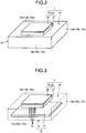
- Fig. 2 is a perspective view illustrating a structure example of the router unit 1 with the antenna according to the embodiment.
- Fig. 3 is a perspective view illustrating an example in which an antenna structure 20 and a transferring unit 11 according to the embodiment are connected.
- the router unit 1 with the antenna has a function of transmitting or receiving a signal, and a function of transferring the signal.
- the router unit 1 with the antenna is mounted in a vehicle 100, and in this example, placed in a rear spoiler 100a of the vehicle 100 as illustrated in Fig. 1 .
- the router unit 1 with the antenna is housed in an internal space of the rear spoiler 100a and fixed thereto, for example. Note that the position of the router unit 1 with the antenna is not limited to the rear spoiler 100a and may be at any place in the vehicle 100 where the transmission and reception of a radio wave are possible.
- the router unit 1 with the antenna includes a router 10 and the antenna structure 20 as illustrated in Fig. 2 and Fig. 3 .
- the router 10 transfers a signal to a transfer destination.
- the router 10 includes the transferring unit 11 and a housing 12.
- the transferring unit 11 is housed in an internal space of the housing 12, and is connected to a planar element 22 of the antenna structure 20 and an electronic device in the vehicle as will be described below.
- the transferring unit 11 includes a routing table where the transfer destination is written, and on the basis of the routing table, transfers the signal, which is output from the planar element 22 of the antenna structure 20, to the electronic device in the vehicle.
- the transferring unit 11 transfers the signal, which is output from the electronic device in the vehicle, to the planar element 22 on the basis of the routing table.
- the housing 12 houses the transferring unit 11.
- the housing 12 includes a plurality of (for example, six) wall parts 12a and is formed to have a box-like shape.
- Each wall part 12a is formed to have a flat plate shape and each pair of wall parts 12a is disposed to face each other; thus, the box-like shape is formed.
- the housing 12 includes the internal space for housing the transferring unit 11 therein.
- Each wall part 12a of the housing 12 includes a main body part 12b formed to have a plate shape by an insulating member such as resin, and a shield part 12c with a conductive property for blocking noise that affects the transferring unit 11.
- the shield part 12c is formed by, for example, providing a conductive metal plate to an external wall surface of the main body part 12b.
- the conductive metal plate is formed in the entire area of the external wall surface of each main body part 12b, and provided to each of all the six wall parts 12a. Note that the conductive metal plate may be provided to a part of the six wall parts 12a.
- the shield part 12c is not limited to the aforementioned structure and may employ another structure.
- each main body part 12b itself may be formed by a conductive metal plate.
- the shield part 12c is larger than the planar element 22 when viewed from a stacking direction of the pattern of the planar element 22 stacked on a dielectric body 21, the stacking direction being described later. That is to say, the shield part 12c includes an overlapping part that overlaps with the planar element 22 and an extension part that is extended outward from the overlapping part, when viewed from the stacking direction.
- the antenna structure 20 includes the dielectric body 21 and the planar element 22 as an antenna element.
- the dielectric body 21 has the dielectric property, is stacked on the surface of the shield part 12c, and is formed to have a flat plate shape.
- the planar element 22 has the conductive property, is stacked on the side of the dielectric body 21 opposite to the shield part 12c, and is formed to have a thin film shape.
- the planar element 22 has, for example, a rectangular shape but the shape is not limited to the rectangular shape.
- the planar element 22 is connected to the transferring unit 11 of the router 10 through a connector cable 23.
- the antenna structure 20 transmits or receives a radio wave (signal) by using the shield part 12c as a ground of the antenna structure 20.
- the antenna structure 20 transmits the signal output from the router 10, for example, to a communication system 101 outside the vehicle.
- the antenna structure 20 receives the signal from the communication system 101 outside the vehicle and outputs the received signal to the router 10.
- the router unit 1 with the antenna includes the router 10 and the antenna structure 20.
- the antenna structure 20 is mounted in the vehicle 100 and includes the dielectric body 21 with the dielectric property and the planar element 22 with the conductive property that is provided to the dielectric body 21.
- the router 10 includes the transferring unit 11 and the housing 12.
- the transferring unit 11 transfers the signal to the transfer destination.
- the housing 12 houses the transferring unit 11, and includes the shield part 12c with the conductive property for blocking the noise that affects the transferring unit 11.
- the antenna structure 20 is provided to the shield part 12c and is connected to the transferring unit 11. Then, the antenna unit 20 transmits or receives the radio wave by using the shield part 12c as the ground of the antenna structure 20.
- the router unit 1 with the antenna can use the shield part 12c of the router 10 also as the ground of the antenna structure 20.
- the increase in the number of components can be suppressed and accordingly, the enlargement of the device can be suppressed.
- the router unit 1 with the antenna since the router unit 1 with the antenna includes the antenna structure 20 in the shield part 12c of the router 10, the distance between the router 10 and the antenna structure 20 can be made relatively short and the attenuation of the signal by the connector cable 23 between the router 10 and the antenna structure 20 can be suppressed.
- the router unit 1 with the antenna can relieve the antenna gain performance and suppress the enlargement of the device.
- the router unit 1 with the antenna can omit a relay unit to be installed between the router 10 and the antenna structure 20.
- the increase in the number of components is suppressed and the attenuation of the signal is suppressed, and accordingly, the enlargement of the device can be suppressed.
- the antenna device 2 includes the antenna structure 20.
- the antenna structure 20 is mounted in the vehicle 100 and includes the dielectric body 21 with the dielectric property and the planar element 22 with the conductive property that is provided to the dielectric body 21.
- the antenna structure 20 is provided to the shield part 12c, connected to the transferring unit 11, and transmits or receives the radio wave by using the shield part 12c as the ground of the antenna structure 20.
- the antenna device 2 obtains the effect similar to that of the router unit 1 with the antenna.
- the antenna structure 20 transmits the signal output from the transferring unit 11 to the communication system 101 outside the vehicle, or outputs the signal received from the communication system 101 outside the vehicle to the transferring unit 11.
- the antenna device 2 can communicate with the outside of the vehicle 100.
- FIG. 4 is a perspective view illustrating a structure example of a router unit 1A with an antenna according to the modification of the embodiment.
- the router unit 1A with the antenna is different from the router unit 1 with the antenna according to the embodiment in that the router unit 1A includes a monopolar element 22A instead of the planar element 22.
- the router unit 1A with the antenna includes the router 10 and an antenna structure 20A as illustrated in Fig. 4 .
- the antenna structure 20A includes a dielectric body 21A and the monopolar element 22A as the antenna element.
- the dielectric body 21A is formed to have a sheet shape, and is disposed to face the shield part 12c of the router 10 with a distance therebetween in the stacking direction. Then, the dielectric body 21A includes a bent part 21a corresponding to one end of the dielectric body 21A that is bent toward the shield part 12c. Between the dielectric body 21A and the shield part 12c, a supporting member (not shown) such as a foamed material with a dielectric property is provided between the dielectric body 21A and the shield part 12c.
- the supporting member supports the dielectric body 21A, and maintains the gap between the dielectric body 21A and the shield part 12c constant.
- the monopolar element 22A has the conductive property, is stacked on the shield part 12c side of the dielectric body 21A, and is formed to have a thin film shape. That is to say, the monopolar element 22A is provided to the dielectric body 21A on a side (inner side) that faces the shield part 12c.
- the monopolar element 22A is connected to the transferring unit 11 of the router 10 through a connector cable (not shown).
- the monopolar element 22A includes a capacitive coupling part 22a that is capacitively coupled with the shield part 12c in a manner that a part of the monopolar element 22A is overlapped with the shield part 12c through the dielectric body 21A at the bent part 21a.
- the antenna structure 20A transmits or receives the radio wave by using the shield part 12c as the ground of the antenna structure 20A.
- the dielectric body 21A is formed to have the sheet shape, is disposed to face the shield part 12c with a distance therebetween, and includes the bent part 21a corresponding to one end of the dielectric body 21A disposed to face the shield part 12c, the one end being bent toward the shield part 12c.
- the monopolar element 22A is provided to the dielectric body 21A on the side of the shield part 12c and includes the capacitive coupling part 22a that is capacitively coupled with the shield part 12c in a manner that a part of the monopolar element 22A is overlapped with the shield part 12c through the dielectric body 21A at the bent part 21a.
- the antenna structure 20A transmits or receives the radio wave by using the shield part 12c as the ground of the antenna structure 20A.
- the router unit 1A with the antenna obtains the effect similar to that of the router unit 1 with the antenna (antenna device 2) according to the embodiment.
- the antenna structure 20 transmits the signal, which is output from the transferring unit 11, to the communication system 101 outside the vehicle or outputs the signal, which is received from the communication system 101 outside the vehicle, to the transferring unit 11; however, the present invention is not limited to this example.
- the antenna structure 20 may transmit the signal, which is output from the transferring unit 11, to a communication unit inside the vehicle or output the signal, which is received from the communication unit inside the vehicle, to the transferring unit 11.
- planar element 22 and the monopolar element 22A are described as the antenna elements; however, the antenna element is not limited to the aforementioned element and may be an antenna with another shape.
- the antenna structure 20 includes one planar element 22 and the antenna structure 20A includes one monopolar element 22A; however, the number of elements is not limited to this number and each of the antenna structures 20 and 20A may include a plurality of, and a plurality of kinds of antenna elements.
Landscapes
- Physics & Mathematics (AREA)
- Electromagnetism (AREA)
- Engineering & Computer Science (AREA)
- Remote Sensing (AREA)
- Details Of Aerials (AREA)
- Waveguide Aerials (AREA)
- Support Of Aerials (AREA)
Abstract
Description
- The present invention relates to an antenna device and a router unit with an antenna.
- One example of the conventionally known antenna devices is an antenna unit disclosed in Japanese Patent Application Laid-open No.
2018-182415 - Incidentally, in the antenna unit according to Japanese Patent Application Laid-open No.
2018-182415 - The present invention has been made in view of the above circumstances, and an object is to provide an antenna device and a router unit with an antenna in which the increase in the number of components and the attenuation of a signal can be suppressed.
- In order to solve the above mentioned problem and achieve the object, a antenna device according to one aspect of the present invention includes an antenna structure that is mounted in a vehicle, and includes a dielectric body with a dielectric property and an antenna element with a conductive property that is provided to the dielectric body, wherein in a router including a transferring unit that transfers a signal to a transfer destination and a housing that houses the transferring unit and includes a shield part with a conductive property for blocking noise that affects the transferring unit, the antenna structure is provided to the shield part, connected to the transferring unit, and transmits or receives a radio wave by using the shield part as a ground of the antenna structure.
- According to another aspect of the present invention, in the antenna device, it is preferable that the antenna structure transmits the signal, which is output from the transferring unit, to a communication system outside the vehicle or outputs the signal, which is received from the communication system outside the vehicle, to the transferring unit.
- According to still another aspect of the present invention, in the antenna device, it is preferable that the shield part is larger than the antenna element when viewed from a stacking direction of a pattern of the antenna element stacked on the dielectric body.
- According to still another aspect of the present invention, in the antenna device, it is preferable that the dielectric body is formed to have a sheet shape, is disposed to face the shield part with a distance therebetween, and includes a bent part corresponding to one end of the dielectric body disposed to face the shield part, the one end being bent toward the shield part, the antenna element is provided to the dielectric body on a side of the shield part and includes a capacitive coupling part that is capacitively coupled with the shield part in a manner that a part of the antenna element is overlapped with the shield part through the dielectric body at the bent part, and the antenna structure transmits or receives the radio wave by using the shield part as the ground of the antenna structure.
- In order to achieve the object, a router unit with an antenna according to still another aspect of the present invention includes an antenna structure that is mounted in a vehicle, and includes a dielectric body with a dielectric property and an antenna element with a conductive property that is provided to the dielectric body; and a router including a transferring unit that transfers a signal to a transfer destination and a housing that houses the transferring unit and includes a shield part with a conductive property for blocking noise that affects the transferring unit, wherein the antenna structure is provided to the shield part, connected to the transferring unit, and transmits or receives a radio wave by using the shield part as a ground of the antenna structure.
- The above and other objects, features, advantages and technical and industrial significance of this invention will be better understood by reading the following detailed description of presently preferred embodiments of the invention, when considered in connection with the accompanying drawings.
-
-
Fig. 1 is a schematic view illustrating an example in which a router unit with an antenna according to one embodiment is mounted; -
Fig. 2 is a perspective view illustrating a structure example of the router unit with the antenna according to the embodiment; -
Fig. 3 is a perspective view illustrating an example in which an antenna structure and a transferring unit according to the embodiment are connected; and -
Fig. 4 is a perspective view illustrating a structure example of a router unit with an antenna according to a modification of the embodiment. - A mode for carrying out the present invention (embodiment) is described in detail with reference to the drawings. However, the present invention is not limited by the content described in the embodiment below. In addition, the component described below includes the component that is easily conceived by a person skilled in the art or that is substantially the same. Furthermore, the structures described below can be combined with each other. Moreover, the structures can be omitted, replaced, or changed variously within the range not departing from the scope of the present invention.
- A
router unit 1 with an antenna and anantenna device 2 according to an embodiment are described with reference to the drawings.Fig. 1 is a schematic view illustrating an example in which therouter unit 1 with the antenna according to the embodiment is mounted.Fig. 2 is a perspective view illustrating a structure example of therouter unit 1 with the antenna according to the embodiment.Fig. 3 is a perspective view illustrating an example in which anantenna structure 20 and a transferringunit 11 according to the embodiment are connected. - The
router unit 1 with the antenna has a function of transmitting or receiving a signal, and a function of transferring the signal. Therouter unit 1 with the antenna is mounted in avehicle 100, and in this example, placed in arear spoiler 100a of thevehicle 100 as illustrated inFig. 1 . Therouter unit 1 with the antenna is housed in an internal space of therear spoiler 100a and fixed thereto, for example. Note that the position of therouter unit 1 with the antenna is not limited to therear spoiler 100a and may be at any place in thevehicle 100 where the transmission and reception of a radio wave are possible. - The
router unit 1 with the antenna includes arouter 10 and theantenna structure 20 as illustrated inFig. 2 and Fig. 3 . Therouter 10 transfers a signal to a transfer destination. Therouter 10 includes the transferringunit 11 and ahousing 12. The transferringunit 11 is housed in an internal space of thehousing 12, and is connected to aplanar element 22 of theantenna structure 20 and an electronic device in the vehicle as will be described below. The transferringunit 11 includes a routing table where the transfer destination is written, and on the basis of the routing table, transfers the signal, which is output from theplanar element 22 of theantenna structure 20, to the electronic device in the vehicle. Moreover, the transferringunit 11 transfers the signal, which is output from the electronic device in the vehicle, to theplanar element 22 on the basis of the routing table. - The
housing 12 houses the transferringunit 11. Thehousing 12 includes a plurality of (for example, six)wall parts 12a and is formed to have a box-like shape. Eachwall part 12a is formed to have a flat plate shape and each pair ofwall parts 12a is disposed to face each other; thus, the box-like shape is formed. Thehousing 12 includes the internal space for housing the transferringunit 11 therein. - Each
wall part 12a of thehousing 12 includes amain body part 12b formed to have a plate shape by an insulating member such as resin, and ashield part 12c with a conductive property for blocking noise that affects the transferringunit 11. Theshield part 12c is formed by, for example, providing a conductive metal plate to an external wall surface of themain body part 12b. The conductive metal plate is formed in the entire area of the external wall surface of eachmain body part 12b, and provided to each of all the sixwall parts 12a. Note that the conductive metal plate may be provided to a part of the sixwall parts 12a. Theshield part 12c is not limited to the aforementioned structure and may employ another structure. In theshield part 12c, for example, eachmain body part 12b itself may be formed by a conductive metal plate. Theshield part 12c is larger than theplanar element 22 when viewed from a stacking direction of the pattern of theplanar element 22 stacked on adielectric body 21, the stacking direction being described later. That is to say, theshield part 12c includes an overlapping part that overlaps with theplanar element 22 and an extension part that is extended outward from the overlapping part, when viewed from the stacking direction. - The
antenna structure 20 includes thedielectric body 21 and theplanar element 22 as an antenna element. Thedielectric body 21 has the dielectric property, is stacked on the surface of theshield part 12c, and is formed to have a flat plate shape. Theplanar element 22 has the conductive property, is stacked on the side of thedielectric body 21 opposite to theshield part 12c, and is formed to have a thin film shape. Theplanar element 22 has, for example, a rectangular shape but the shape is not limited to the rectangular shape. Theplanar element 22 is connected to the transferringunit 11 of therouter 10 through aconnector cable 23. - The
antenna structure 20 transmits or receives a radio wave (signal) by using theshield part 12c as a ground of theantenna structure 20. Theantenna structure 20 transmits the signal output from therouter 10, for example, to acommunication system 101 outside the vehicle. In addition, theantenna structure 20 receives the signal from thecommunication system 101 outside the vehicle and outputs the received signal to therouter 10. - As described above, the
router unit 1 with the antenna according to the embodiment includes therouter 10 and theantenna structure 20. Theantenna structure 20 is mounted in thevehicle 100 and includes thedielectric body 21 with the dielectric property and theplanar element 22 with the conductive property that is provided to thedielectric body 21. Therouter 10 includes the transferringunit 11 and thehousing 12. The transferringunit 11 transfers the signal to the transfer destination. Thehousing 12 houses the transferringunit 11, and includes theshield part 12c with the conductive property for blocking the noise that affects the transferringunit 11. Theantenna structure 20 is provided to theshield part 12c and is connected to the transferringunit 11. Then, theantenna unit 20 transmits or receives the radio wave by using theshield part 12c as the ground of theantenna structure 20. - By this structure, the
router unit 1 with the antenna can use theshield part 12c of therouter 10 also as the ground of theantenna structure 20. Thus, in therouter unit 1 with the antenna, the increase in the number of components can be suppressed and accordingly, the enlargement of the device can be suppressed. In addition, since therouter unit 1 with the antenna includes theantenna structure 20 in theshield part 12c of therouter 10, the distance between therouter 10 and theantenna structure 20 can be made relatively short and the attenuation of the signal by theconnector cable 23 between therouter 10 and theantenna structure 20 can be suppressed. Therouter unit 1 with the antenna can relieve the antenna gain performance and suppress the enlargement of the device. Additionally, therouter unit 1 with the antenna can omit a relay unit to be installed between therouter 10 and theantenna structure 20. Thus, in therouter unit 1 with the antenna, the increase in the number of components is suppressed and the attenuation of the signal is suppressed, and accordingly, the enlargement of the device can be suppressed. - The
antenna device 2 includes theantenna structure 20. Theantenna structure 20 is mounted in thevehicle 100 and includes thedielectric body 21 with the dielectric property and theplanar element 22 with the conductive property that is provided to thedielectric body 21. In therouter 10 including the transferringunit 11 that transfers the signal to the transfer destination and thehousing 12 that houses the transferringunit 11 and includes theshield part 12c with the conductive property for blocking the noise that affects the transferringunit 11, theantenna structure 20 is provided to theshield part 12c, connected to the transferringunit 11, and transmits or receives the radio wave by using theshield part 12c as the ground of theantenna structure 20. By this structure, theantenna device 2 obtains the effect similar to that of therouter unit 1 with the antenna. - In the
antenna device 2, theantenna structure 20 transmits the signal output from the transferringunit 11 to thecommunication system 101 outside the vehicle, or outputs the signal received from thecommunication system 101 outside the vehicle to the transferringunit 11. By this structure, theantenna device 2 can communicate with the outside of thevehicle 100. - In the
antenna device 2, theshield part 12c is larger than theplanar element 22 when viewed from the stacking direction of the pattern of theplanar element 22 stacked on thedielectric body 21. By this structure, theantenna device 2 can secure the antenna gain as appropriate. - Next, a modification of the embodiment is described. In the modification below, the component equivalent to that of the embodiment is denoted by the same reference sign and the detailed description of the corresponding component is omitted.
Fig. 4 is a perspective view illustrating a structure example of arouter unit 1A with an antenna according to the modification of the embodiment. Therouter unit 1A with the antenna is different from therouter unit 1 with the antenna according to the embodiment in that therouter unit 1A includes amonopolar element 22A instead of theplanar element 22. - The
router unit 1A with the antenna (antenna device 2A) includes therouter 10 and anantenna structure 20A as illustrated inFig. 4 . Theantenna structure 20A includes adielectric body 21A and themonopolar element 22A as the antenna element. - The
dielectric body 21A is formed to have a sheet shape, and is disposed to face theshield part 12c of therouter 10 with a distance therebetween in the stacking direction. Then, thedielectric body 21A includes abent part 21a corresponding to one end of thedielectric body 21A that is bent toward theshield part 12c. Between thedielectric body 21A and theshield part 12c, a supporting member (not shown) such as a foamed material with a dielectric property is provided. The supporting member supports thedielectric body 21A, and maintains the gap between thedielectric body 21A and theshield part 12c constant. - The
monopolar element 22A has the conductive property, is stacked on theshield part 12c side of thedielectric body 21A, and is formed to have a thin film shape. That is to say, themonopolar element 22A is provided to thedielectric body 21A on a side (inner side) that faces theshield part 12c. Themonopolar element 22A is connected to the transferringunit 11 of therouter 10 through a connector cable (not shown). Themonopolar element 22A includes acapacitive coupling part 22a that is capacitively coupled with theshield part 12c in a manner that a part of themonopolar element 22A is overlapped with theshield part 12c through thedielectric body 21A at thebent part 21a. Theantenna structure 20A transmits or receives the radio wave by using theshield part 12c as the ground of theantenna structure 20A. - As described above, in the
router unit 1A with the antenna (antenna device 2A), thedielectric body 21A is formed to have the sheet shape, is disposed to face theshield part 12c with a distance therebetween, and includes thebent part 21a corresponding to one end of thedielectric body 21A disposed to face theshield part 12c, the one end being bent toward theshield part 12c. Themonopolar element 22A is provided to thedielectric body 21A on the side of theshield part 12c and includes thecapacitive coupling part 22a that is capacitively coupled with theshield part 12c in a manner that a part of themonopolar element 22A is overlapped with theshield part 12c through thedielectric body 21A at thebent part 21a. Theantenna structure 20A transmits or receives the radio wave by using theshield part 12c as the ground of theantenna structure 20A. By this structure, therouter unit 1A with the antenna (antenna device 2A) obtains the effect similar to that of therouter unit 1 with the antenna (antenna device 2) according to the embodiment. - In the above example, the
antenna structure 20 transmits the signal, which is output from the transferringunit 11, to thecommunication system 101 outside the vehicle or outputs the signal, which is received from thecommunication system 101 outside the vehicle, to the transferringunit 11; however, the present invention is not limited to this example. Theantenna structure 20 may transmit the signal, which is output from the transferringunit 11, to a communication unit inside the vehicle or output the signal, which is received from the communication unit inside the vehicle, to the transferringunit 11. - The
planar element 22 and themonopolar element 22A are described as the antenna elements; however, the antenna element is not limited to the aforementioned element and may be an antenna with another shape. - The
antenna structure 20 includes oneplanar element 22 and theantenna structure 20A includes onemonopolar element 22A; however, the number of elements is not limited to this number and each of theantenna structures - In the antenna device and the router unit with the antenna according to the embodiment, the increase in the number of components can be suppressed and the attenuation of the signal can be suppressed by the use of the shield part of the router as the ground of the antenna structure.
- Although the invention has been described with respect to specific embodiments for a complete and clear disclosure, the appended claims are not to be thus limited but are to be construed as embodying all modifications and alternative constructions that may occur to one skilled in the art that fairly fall within the basic teaching herein set forth.
Claims (5)
- An antenna device (2, 2A), comprising:an antenna structure (20, 20A) that is mounted in a vehicle (100), and includes a dielectric body (21, 21A) with a dielectric property and an antenna element (22, 22A) with a conductive property that is provided to the dielectric body (21, 21A), whereinin a router (10) including a transferring unit (11) that transfers a signal to a transfer destination and a housing (12) that houses the transferring unit (11) and includes a shield part (12b) with a conductive property for blocking noise that affects the transferring unit (11), the antenna structure (20, 20A) is provided to the shield part (12b), connected to the transferring unit (11), and transmits or receives a radio wave by using the shield part (12b) as a ground of the antenna structure (20, 20A).
- The antenna device (2, 2A) according to claim 1, wherein
the antenna structure (20, 20A) transmits the signal, which is output from the transferring unit (11), to a communication system (101) outside the vehicle (100) or outputs the signal, which is received from the communication system (101) outside the vehicle (100), to the transferring unit (11). - The antenna device (2, 2A) according to claim 1 or 2, wherein
the shield part (12b) is larger than the antenna element (22, 22A) when viewed from a stacking direction of a pattern of the antenna element (22, 22A) stacked on the dielectric body (21, 21A). - The antenna device (2A) according to any one of claims 1 to 3, wherein
the dielectric body (21A) is formed to have a sheet shape, is disposed to face the shield part (12b) with a distance therebetween, and includes a bent part (21a) corresponding to one end of the dielectric body (21A) disposed to face the shield part (12b), the one end being bent toward the shield part (12b),
the antenna element (22A) is provided to the dielectric body (21A) on a side of the shield part (12b) and includes a capacitive coupling part (22a) that is capacitively coupled with the shield part (12b) in a manner that a part of the antenna element (22A) is overlapped with the shield part (12b) through the dielectric body (21A) at the bent part (21a), and
the antenna structure (20A) transmits or receives the radio wave by using the shield part (12b) as the ground of the antenna structure (20A). - A router unit with an antenna (1, 1A), comprising:an antenna structure (20, 20A) that is mounted in a vehicle (100), and includes a dielectric body (21, 21A) with a dielectric property and an antenna element (22, 22A) with a conductive property that is provided to the dielectric body (21, 21A); anda router (10) including a transferring unit (11) that transfers a signal to a transfer destination and a housing (12) that houses the transferring unit (11) and includes a shield part (12b) with a conductive property for blocking noise that affects the transferring unit (11), whereinthe antenna structure (20, 20A) is provided to the shield part (12b), connected to the transferring unit (11), and transmits or receives a radio wave by using the shield part (12b) as a ground of the antenna structure (20, 20A).
Applications Claiming Priority (1)
| Application Number | Priority Date | Filing Date | Title |
|---|---|---|---|
| JP2019012741A JP6932731B2 (en) | 2019-01-29 | 2019-01-29 | Antenna device and router unit with antenna |
Publications (2)
| Publication Number | Publication Date |
|---|---|
| EP3691031A1 true EP3691031A1 (en) | 2020-08-05 |
| EP3691031B1 EP3691031B1 (en) | 2023-02-01 |
Family
ID=69055839
Family Applications (1)
| Application Number | Title | Priority Date | Filing Date |
|---|---|---|---|
| EP19220008.7A Active EP3691031B1 (en) | 2019-01-29 | 2019-12-30 | Antenna device and router unit with antenna |
Country Status (4)
| Country | Link |
|---|---|
| US (1) | US11121451B2 (en) |
| EP (1) | EP3691031B1 (en) |
| JP (1) | JP6932731B2 (en) |
| CN (1) | CN111490332B (en) |
Families Citing this family (1)
| Publication number | Priority date | Publication date | Assignee | Title |
|---|---|---|---|---|
| US11539137B2 (en) * | 2019-08-27 | 2022-12-27 | 2J Antennas Usa, Corporation | Socket antenna module and related transceiver assembly |
Citations (4)
| Publication number | Priority date | Publication date | Assignee | Title |
|---|---|---|---|---|
| EP0590955A2 (en) * | 1992-09-30 | 1994-04-06 | Loral Aerospace Corporation | Multiple band antenna |
| US20130120210A1 (en) * | 2011-11-14 | 2013-05-16 | Continental Automotive Systems, Inc. | Gps antenna on-shield/housing with grounding |
| WO2017211534A1 (en) * | 2016-06-09 | 2017-12-14 | Hirschmann Car Communication Gmbh | Communication system of a vehicle having improved heat management |
| JP2018182415A (en) | 2017-04-05 | 2018-11-15 | 矢崎総業株式会社 | Antenna unit |
Family Cites Families (10)
| Publication number | Priority date | Publication date | Assignee | Title |
|---|---|---|---|---|
| US6215454B1 (en) * | 1998-02-20 | 2001-04-10 | Qualcomm, Inc. | Multi-layered shielded substrate antenna |
| JP2005286794A (en) * | 2004-03-30 | 2005-10-13 | Clarion Co Ltd | Antenna unit |
| JP4264040B2 (en) * | 2004-09-01 | 2009-05-13 | アルプス電気株式会社 | Antenna device |
| US7973722B1 (en) * | 2007-08-28 | 2011-07-05 | Apple Inc. | Electronic device with conductive housing and near field antenna |
| JP6011910B2 (en) * | 2012-05-07 | 2016-10-25 | 日立金属株式会社 | Antenna device |
| US9093750B2 (en) * | 2013-09-12 | 2015-07-28 | Laird Technologies, Inc. | Multiband MIMO vehicular antenna assemblies with DSRC capabilities |
| JP5989722B2 (en) * | 2014-08-04 | 2016-09-07 | 原田工業株式会社 | Antenna device |
| CN105206932A (en) * | 2015-09-17 | 2015-12-30 | 成都汇丁科技有限公司 | Double-inverted F antenna shielding structure |
| JP6393706B2 (en) * | 2016-04-28 | 2018-09-19 | 矢崎総業株式会社 | Roof module |
| WO2018110671A1 (en) * | 2016-12-16 | 2018-06-21 | 株式会社ヨコオ | Antenna device |
-
2019
- 2019-01-29 JP JP2019012741A patent/JP6932731B2/en active Active
- 2019-12-23 US US16/725,186 patent/US11121451B2/en active Active
- 2019-12-26 CN CN201911366605.1A patent/CN111490332B/en active Active
- 2019-12-30 EP EP19220008.7A patent/EP3691031B1/en active Active
Patent Citations (4)
| Publication number | Priority date | Publication date | Assignee | Title |
|---|---|---|---|---|
| EP0590955A2 (en) * | 1992-09-30 | 1994-04-06 | Loral Aerospace Corporation | Multiple band antenna |
| US20130120210A1 (en) * | 2011-11-14 | 2013-05-16 | Continental Automotive Systems, Inc. | Gps antenna on-shield/housing with grounding |
| WO2017211534A1 (en) * | 2016-06-09 | 2017-12-14 | Hirschmann Car Communication Gmbh | Communication system of a vehicle having improved heat management |
| JP2018182415A (en) | 2017-04-05 | 2018-11-15 | 矢崎総業株式会社 | Antenna unit |
Also Published As
| Publication number | Publication date |
|---|---|
| JP2020123760A (en) | 2020-08-13 |
| US20200243945A1 (en) | 2020-07-30 |
| CN111490332B (en) | 2021-07-30 |
| CN111490332A (en) | 2020-08-04 |
| EP3691031B1 (en) | 2023-02-01 |
| US11121451B2 (en) | 2021-09-14 |
| JP6932731B2 (en) | 2021-09-08 |
Similar Documents
| Publication | Publication Date | Title |
|---|---|---|
| CN109037918B (en) | Antenna assembly and electronic equipment | |
| US7535422B2 (en) | Notebook and antenna structure thereof | |
| WO2020010923A1 (en) | Antenna assembly and electronic device | |
| CN111244600B (en) | Antenna structure and wireless communication device with same | |
| US10840592B2 (en) | Electronic device and antenna assembly thereof | |
| US7372412B2 (en) | Transceiver-integrated antenna | |
| CN108417996A (en) | Antenna components and mobile terminals | |
| US12189435B2 (en) | Foldable apparatus and terminal device | |
| US7498995B2 (en) | UWB antenna having 270 degree coverage and system thereof | |
| US11121451B2 (en) | Antenna device and router unit with antenna | |
| WO2023027519A1 (en) | Shield can having antenna function | |
| JPH08125433A (en) | Repeater for in-building radio communication | |
| JPH10107674A (en) | Integrated flat antenna and radio frequency device for point-to-point microwave radio | |
| WO2021098042A1 (en) | Antenna, middle terminal frame, and terminal | |
| JP4655095B2 (en) | Antenna device | |
| JP7635921B2 (en) | MIMO antenna device | |
| CN210607605U (en) | Antenna device and mobile payment terminal | |
| EP3648244B1 (en) | Antenna unit | |
| CN115084830A (en) | Antenna module and terminal | |
| CN215008571U (en) | Low-profile GNSS antenna | |
| US7146201B2 (en) | Portable wireless apparatus | |
| CN112886231A (en) | Antenna and terminal equipment | |
| TWI712216B (en) | Antenna structure and wireless communication device using the same | |
| US20100207831A1 (en) | Loop Dipole Antenna Module | |
| JP2015053534A (en) | Antenna device |
Legal Events
| Date | Code | Title | Description |
|---|---|---|---|
| PUAI | Public reference made under article 153(3) epc to a published international application that has entered the european phase |
Free format text: ORIGINAL CODE: 0009012 |
|
| STAA | Information on the status of an ep patent application or granted ep patent |
Free format text: STATUS: REQUEST FOR EXAMINATION WAS MADE |
|
| 17P | Request for examination filed |
Effective date: 20191230 |
|
| AK | Designated contracting states |
Kind code of ref document: A1 Designated state(s): AL AT BE BG CH CY CZ DE DK EE ES FI FR GB GR HR HU IE IS IT LI LT LU LV MC MK MT NL NO PL PT RO RS SE SI SK SM TR |
|
| AX | Request for extension of the european patent |
Extension state: BA ME |
|
| RBV | Designated contracting states (corrected) |
Designated state(s): AL AT BE BG CH CY CZ DE DK EE ES FI FR GB GR HR HU IE IS IT LI LT LU LV MC MK MT NL NO PL PT RO RS SE SI SK SM TR |
|
| STAA | Information on the status of an ep patent application or granted ep patent |
Free format text: STATUS: EXAMINATION IS IN PROGRESS |
|
| 17Q | First examination report despatched |
Effective date: 20211103 |
|
| GRAP | Despatch of communication of intention to grant a patent |
Free format text: ORIGINAL CODE: EPIDOSNIGR1 |
|
| STAA | Information on the status of an ep patent application or granted ep patent |
Free format text: STATUS: GRANT OF PATENT IS INTENDED |
|
| RIC1 | Information provided on ipc code assigned before grant |
Ipc: H01Q 9/42 20060101ALN20220920BHEP Ipc: H01Q 9/04 20060101ALN20220920BHEP Ipc: H01Q 1/52 20060101ALI20220920BHEP Ipc: H01Q 1/32 20060101AFI20220920BHEP |
|
| INTG | Intention to grant announced |
Effective date: 20221026 |
|
| GRAS | Grant fee paid |
Free format text: ORIGINAL CODE: EPIDOSNIGR3 |
|
| GRAA | (expected) grant |
Free format text: ORIGINAL CODE: 0009210 |
|
| STAA | Information on the status of an ep patent application or granted ep patent |
Free format text: STATUS: THE PATENT HAS BEEN GRANTED |
|
| AK | Designated contracting states |
Kind code of ref document: B1 Designated state(s): AL AT BE BG CH CY CZ DE DK EE ES FI FR GB GR HR HU IE IS IT LI LT LU LV MC MK MT NL NO PL PT RO RS SE SI SK SM TR |
|
| REG | Reference to a national code |
Ref country code: GB Ref legal event code: FG4D |
|
| REG | Reference to a national code |
Ref country code: CH Ref legal event code: EP Ref country code: AT Ref legal event code: REF Ref document number: 1547162 Country of ref document: AT Kind code of ref document: T Effective date: 20230215 |
|
| REG | Reference to a national code |
Ref country code: DE Ref legal event code: R096 Ref document number: 602019025009 Country of ref document: DE |
|
| REG | Reference to a national code |
Ref country code: IE Ref legal event code: FG4D |
|
| REG | Reference to a national code |
Ref country code: LT Ref legal event code: MG9D |
|
| RAP4 | Party data changed (patent owner data changed or rights of a patent transferred) |
Owner name: YAZAKI CORPORATION |
|
| REG | Reference to a national code |
Ref country code: NL Ref legal event code: MP Effective date: 20230201 |
|
| REG | Reference to a national code |
Ref country code: AT Ref legal event code: MK05 Ref document number: 1547162 Country of ref document: AT Kind code of ref document: T Effective date: 20230201 |
|
| PG25 | Lapsed in a contracting state [announced via postgrant information from national office to epo] |
Ref country code: RS Free format text: LAPSE BECAUSE OF FAILURE TO SUBMIT A TRANSLATION OF THE DESCRIPTION OR TO PAY THE FEE WITHIN THE PRESCRIBED TIME-LIMIT Effective date: 20230201 Ref country code: PT Free format text: LAPSE BECAUSE OF FAILURE TO SUBMIT A TRANSLATION OF THE DESCRIPTION OR TO PAY THE FEE WITHIN THE PRESCRIBED TIME-LIMIT Effective date: 20230601 Ref country code: NO Free format text: LAPSE BECAUSE OF FAILURE TO SUBMIT A TRANSLATION OF THE DESCRIPTION OR TO PAY THE FEE WITHIN THE PRESCRIBED TIME-LIMIT Effective date: 20230501 Ref country code: NL Free format text: LAPSE BECAUSE OF FAILURE TO SUBMIT A TRANSLATION OF THE DESCRIPTION OR TO PAY THE FEE WITHIN THE PRESCRIBED TIME-LIMIT Effective date: 20230201 Ref country code: LV Free format text: LAPSE BECAUSE OF FAILURE TO SUBMIT A TRANSLATION OF THE DESCRIPTION OR TO PAY THE FEE WITHIN THE PRESCRIBED TIME-LIMIT Effective date: 20230201 Ref country code: LT Free format text: LAPSE BECAUSE OF FAILURE TO SUBMIT A TRANSLATION OF THE DESCRIPTION OR TO PAY THE FEE WITHIN THE PRESCRIBED TIME-LIMIT Effective date: 20230201 Ref country code: HR Free format text: LAPSE BECAUSE OF FAILURE TO SUBMIT A TRANSLATION OF THE DESCRIPTION OR TO PAY THE FEE WITHIN THE PRESCRIBED TIME-LIMIT Effective date: 20230201 Ref country code: ES Free format text: LAPSE BECAUSE OF FAILURE TO SUBMIT A TRANSLATION OF THE DESCRIPTION OR TO PAY THE FEE WITHIN THE PRESCRIBED TIME-LIMIT Effective date: 20230201 Ref country code: AT Free format text: LAPSE BECAUSE OF FAILURE TO SUBMIT A TRANSLATION OF THE DESCRIPTION OR TO PAY THE FEE WITHIN THE PRESCRIBED TIME-LIMIT Effective date: 20230201 |
|
| PG25 | Lapsed in a contracting state [announced via postgrant information from national office to epo] |
Ref country code: SE Free format text: LAPSE BECAUSE OF FAILURE TO SUBMIT A TRANSLATION OF THE DESCRIPTION OR TO PAY THE FEE WITHIN THE PRESCRIBED TIME-LIMIT Effective date: 20230201 Ref country code: PL Free format text: LAPSE BECAUSE OF FAILURE TO SUBMIT A TRANSLATION OF THE DESCRIPTION OR TO PAY THE FEE WITHIN THE PRESCRIBED TIME-LIMIT Effective date: 20230201 Ref country code: IS Free format text: LAPSE BECAUSE OF FAILURE TO SUBMIT A TRANSLATION OF THE DESCRIPTION OR TO PAY THE FEE WITHIN THE PRESCRIBED TIME-LIMIT Effective date: 20230601 Ref country code: GR Free format text: LAPSE BECAUSE OF FAILURE TO SUBMIT A TRANSLATION OF THE DESCRIPTION OR TO PAY THE FEE WITHIN THE PRESCRIBED TIME-LIMIT Effective date: 20230502 Ref country code: FI Free format text: LAPSE BECAUSE OF FAILURE TO SUBMIT A TRANSLATION OF THE DESCRIPTION OR TO PAY THE FEE WITHIN THE PRESCRIBED TIME-LIMIT Effective date: 20230201 |
|
| PG25 | Lapsed in a contracting state [announced via postgrant information from national office to epo] |
Ref country code: SM Free format text: LAPSE BECAUSE OF FAILURE TO SUBMIT A TRANSLATION OF THE DESCRIPTION OR TO PAY THE FEE WITHIN THE PRESCRIBED TIME-LIMIT Effective date: 20230201 Ref country code: RO Free format text: LAPSE BECAUSE OF FAILURE TO SUBMIT A TRANSLATION OF THE DESCRIPTION OR TO PAY THE FEE WITHIN THE PRESCRIBED TIME-LIMIT Effective date: 20230201 Ref country code: EE Free format text: LAPSE BECAUSE OF FAILURE TO SUBMIT A TRANSLATION OF THE DESCRIPTION OR TO PAY THE FEE WITHIN THE PRESCRIBED TIME-LIMIT Effective date: 20230201 Ref country code: DK Free format text: LAPSE BECAUSE OF FAILURE TO SUBMIT A TRANSLATION OF THE DESCRIPTION OR TO PAY THE FEE WITHIN THE PRESCRIBED TIME-LIMIT Effective date: 20230201 Ref country code: CZ Free format text: LAPSE BECAUSE OF FAILURE TO SUBMIT A TRANSLATION OF THE DESCRIPTION OR TO PAY THE FEE WITHIN THE PRESCRIBED TIME-LIMIT Effective date: 20230201 |
|
| REG | Reference to a national code |
Ref country code: DE Ref legal event code: R097 Ref document number: 602019025009 Country of ref document: DE |
|
| PG25 | Lapsed in a contracting state [announced via postgrant information from national office to epo] |
Ref country code: SK Free format text: LAPSE BECAUSE OF FAILURE TO SUBMIT A TRANSLATION OF THE DESCRIPTION OR TO PAY THE FEE WITHIN THE PRESCRIBED TIME-LIMIT Effective date: 20230201 |
|
| PLBE | No opposition filed within time limit |
Free format text: ORIGINAL CODE: 0009261 |
|
| STAA | Information on the status of an ep patent application or granted ep patent |
Free format text: STATUS: NO OPPOSITION FILED WITHIN TIME LIMIT |
|
| 26N | No opposition filed |
Effective date: 20231103 |
|
| PG25 | Lapsed in a contracting state [announced via postgrant information from national office to epo] |
Ref country code: SI Free format text: LAPSE BECAUSE OF FAILURE TO SUBMIT A TRANSLATION OF THE DESCRIPTION OR TO PAY THE FEE WITHIN THE PRESCRIBED TIME-LIMIT Effective date: 20230201 |
|
| PG25 | Lapsed in a contracting state [announced via postgrant information from national office to epo] |
Ref country code: IT Free format text: LAPSE BECAUSE OF FAILURE TO SUBMIT A TRANSLATION OF THE DESCRIPTION OR TO PAY THE FEE WITHIN THE PRESCRIBED TIME-LIMIT Effective date: 20230201 |
|
| REG | Reference to a national code |
Ref country code: CH Ref legal event code: PL |
|
| PG25 | Lapsed in a contracting state [announced via postgrant information from national office to epo] |
Ref country code: LU Free format text: LAPSE BECAUSE OF NON-PAYMENT OF DUE FEES Effective date: 20231230 |
|
| PG25 | Lapsed in a contracting state [announced via postgrant information from national office to epo] |
Ref country code: MC Free format text: LAPSE BECAUSE OF FAILURE TO SUBMIT A TRANSLATION OF THE DESCRIPTION OR TO PAY THE FEE WITHIN THE PRESCRIBED TIME-LIMIT Effective date: 20230201 |
|
| GBPC | Gb: european patent ceased through non-payment of renewal fee |
Effective date: 20231230 |
|
| REG | Reference to a national code |
Ref country code: BE Ref legal event code: MM Effective date: 20231231 |
|
| PG25 | Lapsed in a contracting state [announced via postgrant information from national office to epo] |
Ref country code: MC Free format text: LAPSE BECAUSE OF FAILURE TO SUBMIT A TRANSLATION OF THE DESCRIPTION OR TO PAY THE FEE WITHIN THE PRESCRIBED TIME-LIMIT Effective date: 20230201 Ref country code: LU Free format text: LAPSE BECAUSE OF NON-PAYMENT OF DUE FEES Effective date: 20231230 |
|
| REG | Reference to a national code |
Ref country code: IE Ref legal event code: MM4A |
|
| PG25 | Lapsed in a contracting state [announced via postgrant information from national office to epo] |
Ref country code: IE Free format text: LAPSE BECAUSE OF NON-PAYMENT OF DUE FEES Effective date: 20231230 |
|
| PG25 | Lapsed in a contracting state [announced via postgrant information from national office to epo] |
Ref country code: GB Free format text: LAPSE BECAUSE OF NON-PAYMENT OF DUE FEES Effective date: 20231230 |
|
| PG25 | Lapsed in a contracting state [announced via postgrant information from national office to epo] |
Ref country code: BE Free format text: LAPSE BECAUSE OF NON-PAYMENT OF DUE FEES Effective date: 20231231 |
|
| PG25 | Lapsed in a contracting state [announced via postgrant information from national office to epo] |
Ref country code: FR Free format text: LAPSE BECAUSE OF NON-PAYMENT OF DUE FEES Effective date: 20231231 |
|
| PG25 | Lapsed in a contracting state [announced via postgrant information from national office to epo] |
Ref country code: CH Free format text: LAPSE BECAUSE OF NON-PAYMENT OF DUE FEES Effective date: 20231231 |
|
| PG25 | Lapsed in a contracting state [announced via postgrant information from national office to epo] |
Ref country code: IE Free format text: LAPSE BECAUSE OF NON-PAYMENT OF DUE FEES Effective date: 20231230 Ref country code: GB Free format text: LAPSE BECAUSE OF NON-PAYMENT OF DUE FEES Effective date: 20231230 Ref country code: FR Free format text: LAPSE BECAUSE OF NON-PAYMENT OF DUE FEES Effective date: 20231231 Ref country code: CH Free format text: LAPSE BECAUSE OF NON-PAYMENT OF DUE FEES Effective date: 20231231 Ref country code: BE Free format text: LAPSE BECAUSE OF NON-PAYMENT OF DUE FEES Effective date: 20231231 |
|
| PG25 | Lapsed in a contracting state [announced via postgrant information from national office to epo] |
Ref country code: BG Free format text: LAPSE BECAUSE OF FAILURE TO SUBMIT A TRANSLATION OF THE DESCRIPTION OR TO PAY THE FEE WITHIN THE PRESCRIBED TIME-LIMIT Effective date: 20230201 |
|
| PG25 | Lapsed in a contracting state [announced via postgrant information from national office to epo] |
Ref country code: BG Free format text: LAPSE BECAUSE OF FAILURE TO SUBMIT A TRANSLATION OF THE DESCRIPTION OR TO PAY THE FEE WITHIN THE PRESCRIBED TIME-LIMIT Effective date: 20230201 |
|
| PG25 | Lapsed in a contracting state [announced via postgrant information from national office to epo] |
Ref country code: CY Free format text: LAPSE BECAUSE OF FAILURE TO SUBMIT A TRANSLATION OF THE DESCRIPTION OR TO PAY THE FEE WITHIN THE PRESCRIBED TIME-LIMIT; INVALID AB INITIO Effective date: 20191230 |
|
| PG25 | Lapsed in a contracting state [announced via postgrant information from national office to epo] |
Ref country code: HU Free format text: LAPSE BECAUSE OF FAILURE TO SUBMIT A TRANSLATION OF THE DESCRIPTION OR TO PAY THE FEE WITHIN THE PRESCRIBED TIME-LIMIT; INVALID AB INITIO Effective date: 20191230 |
|
| PG25 | Lapsed in a contracting state [announced via postgrant information from national office to epo] |
Ref country code: TR Free format text: LAPSE BECAUSE OF FAILURE TO SUBMIT A TRANSLATION OF THE DESCRIPTION OR TO PAY THE FEE WITHIN THE PRESCRIBED TIME-LIMIT Effective date: 20230201 |
|
| PGFP | Annual fee paid to national office [announced via postgrant information from national office to epo] |
Ref country code: DE Payment date: 20251104 Year of fee payment: 7 |