EP3690859B1 - Method for monitoring blind spot of cycle using smart helmet for cycle rider and blind spot monitoring device using them - Google Patents
Method for monitoring blind spot of cycle using smart helmet for cycle rider and blind spot monitoring device using them Download PDFInfo
- Publication number
- EP3690859B1 EP3690859B1 EP20153072.2A EP20153072A EP3690859B1 EP 3690859 B1 EP3690859 B1 EP 3690859B1 EP 20153072 A EP20153072 A EP 20153072A EP 3690859 B1 EP3690859 B1 EP 3690859B1
- Authority
- EP
- European Patent Office
- Prior art keywords
- cycle
- training
- layer
- objects
- rider
- Prior art date
- Legal status (The legal status is an assumption and is not a legal conclusion. Google has not performed a legal analysis and makes no representation as to the accuracy of the status listed.)
- Active
Links
Images



Classifications
-
- G—PHYSICS
- G06—COMPUTING OR CALCULATING; COUNTING
- G06N—COMPUTING ARRANGEMENTS BASED ON SPECIFIC COMPUTATIONAL MODELS
- G06N3/00—Computing arrangements based on biological models
- G06N3/02—Neural networks
- G06N3/08—Learning methods
- G06N3/084—Backpropagation, e.g. using gradient descent
-
- H—ELECTRICITY
- H04—ELECTRIC COMMUNICATION TECHNIQUE
- H04W—WIRELESS COMMUNICATION NETWORKS
- H04W4/00—Services specially adapted for wireless communication networks; Facilities therefor
- H04W4/30—Services specially adapted for particular environments, situations or purposes
- H04W4/40—Services specially adapted for particular environments, situations or purposes for vehicles, e.g. vehicle-to-pedestrians [V2P]
- H04W4/44—Services specially adapted for particular environments, situations or purposes for vehicles, e.g. vehicle-to-pedestrians [V2P] for communication between vehicles and infrastructures, e.g. vehicle-to-cloud [V2C] or vehicle-to-home [V2H]
-
- A—HUMAN NECESSITIES
- A42—HEADWEAR
- A42B—HATS; HEAD COVERINGS
- A42B3/00—Helmets; Helmet covers ; Other protective head coverings
- A42B3/04—Parts, details or accessories of helmets
- A42B3/0406—Accessories for helmets
-
- A—HUMAN NECESSITIES
- A42—HEADWEAR
- A42B—HATS; HEAD COVERINGS
- A42B3/00—Helmets; Helmet covers ; Other protective head coverings
- A42B3/04—Parts, details or accessories of helmets
- A42B3/0406—Accessories for helmets
- A42B3/042—Optical devices
- A42B3/0426—Rear view devices or the like
-
- A—HUMAN NECESSITIES
- A42—HEADWEAR
- A42B—HATS; HEAD COVERINGS
- A42B3/00—Helmets; Helmet covers ; Other protective head coverings
- A42B3/04—Parts, details or accessories of helmets
- A42B3/0406—Accessories for helmets
- A42B3/0433—Detecting, signalling or lighting devices
-
- A—HUMAN NECESSITIES
- A42—HEADWEAR
- A42B—HATS; HEAD COVERINGS
- A42B3/00—Helmets; Helmet covers ; Other protective head coverings
- A42B3/04—Parts, details or accessories of helmets
- A42B3/0406—Accessories for helmets
- A42B3/0433—Detecting, signalling or lighting devices
- A42B3/046—Means for detecting hazards or accidents
-
- A—HUMAN NECESSITIES
- A42—HEADWEAR
- A42B—HATS; HEAD COVERINGS
- A42B3/00—Helmets; Helmet covers ; Other protective head coverings
- A42B3/04—Parts, details or accessories of helmets
- A42B3/30—Mounting radio sets or communication systems
-
- B—PERFORMING OPERATIONS; TRANSPORTING
- B60—VEHICLES IN GENERAL
- B60W—CONJOINT CONTROL OF VEHICLE SUB-UNITS OF DIFFERENT TYPE OR DIFFERENT FUNCTION; CONTROL SYSTEMS SPECIALLY ADAPTED FOR HYBRID VEHICLES; ROAD VEHICLE DRIVE CONTROL SYSTEMS FOR PURPOSES NOT RELATED TO THE CONTROL OF A PARTICULAR SUB-UNIT
- B60W50/00—Details of control systems for road vehicle drive control not related to the control of a particular sub-unit, e.g. process diagnostic or vehicle driver interfaces
- B60W50/08—Interaction between the driver and the control system
- B60W50/14—Means for informing the driver, warning the driver or prompting a driver intervention
-
- G—PHYSICS
- G01—MEASURING; TESTING
- G01S—RADIO DIRECTION-FINDING; RADIO NAVIGATION; DETERMINING DISTANCE OR VELOCITY BY USE OF RADIO WAVES; LOCATING OR PRESENCE-DETECTING BY USE OF THE REFLECTION OR RERADIATION OF RADIO WAVES; ANALOGOUS ARRANGEMENTS USING OTHER WAVES
- G01S13/00—Systems using the reflection or reradiation of radio waves, e.g. radar systems; Analogous systems using reflection or reradiation of waves whose nature or wavelength is irrelevant or unspecified
- G01S13/88—Radar or analogous systems specially adapted for specific applications
- G01S13/93—Radar or analogous systems specially adapted for specific applications for anti-collision purposes
- G01S13/931—Radar or analogous systems specially adapted for specific applications for anti-collision purposes of land vehicles
-
- G—PHYSICS
- G02—OPTICS
- G02B—OPTICAL ELEMENTS, SYSTEMS OR APPARATUS
- G02B27/00—Optical systems or apparatus not provided for by any of the groups G02B1/00 - G02B26/00, G02B30/00
- G02B27/01—Head-up displays
- G02B27/017—Head mounted
- G02B27/0172—Head mounted characterised by optical features
-
- G—PHYSICS
- G06—COMPUTING OR CALCULATING; COUNTING
- G06N—COMPUTING ARRANGEMENTS BASED ON SPECIFIC COMPUTATIONAL MODELS
- G06N3/00—Computing arrangements based on biological models
- G06N3/02—Neural networks
- G06N3/04—Architecture, e.g. interconnection topology
- G06N3/045—Combinations of networks
-
- G—PHYSICS
- G06—COMPUTING OR CALCULATING; COUNTING
- G06N—COMPUTING ARRANGEMENTS BASED ON SPECIFIC COMPUTATIONAL MODELS
- G06N3/00—Computing arrangements based on biological models
- G06N3/02—Neural networks
- G06N3/04—Architecture, e.g. interconnection topology
- G06N3/0464—Convolutional networks [CNN, ConvNet]
-
- G—PHYSICS
- G06—COMPUTING OR CALCULATING; COUNTING
- G06N—COMPUTING ARRANGEMENTS BASED ON SPECIFIC COMPUTATIONAL MODELS
- G06N3/00—Computing arrangements based on biological models
- G06N3/02—Neural networks
- G06N3/08—Learning methods
- G06N3/09—Supervised learning
-
- G—PHYSICS
- G06—COMPUTING OR CALCULATING; COUNTING
- G06V—IMAGE OR VIDEO RECOGNITION OR UNDERSTANDING
- G06V10/00—Arrangements for image or video recognition or understanding
- G06V10/40—Extraction of image or video features
- G06V10/44—Local feature extraction by analysis of parts of the pattern, e.g. by detecting edges, contours, loops, corners, strokes or intersections; Connectivity analysis, e.g. of connected components
- G06V10/443—Local feature extraction by analysis of parts of the pattern, e.g. by detecting edges, contours, loops, corners, strokes or intersections; Connectivity analysis, e.g. of connected components by matching or filtering
- G06V10/449—Biologically inspired filters, e.g. difference of Gaussians [DoG] or Gabor filters
- G06V10/451—Biologically inspired filters, e.g. difference of Gaussians [DoG] or Gabor filters with interaction between the filter responses, e.g. cortical complex cells
- G06V10/454—Integrating the filters into a hierarchical structure, e.g. convolutional neural networks [CNN]
-
- G—PHYSICS
- G06—COMPUTING OR CALCULATING; COUNTING
- G06V—IMAGE OR VIDEO RECOGNITION OR UNDERSTANDING
- G06V10/00—Arrangements for image or video recognition or understanding
- G06V10/70—Arrangements for image or video recognition or understanding using pattern recognition or machine learning
- G06V10/82—Arrangements for image or video recognition or understanding using pattern recognition or machine learning using neural networks
-
- G—PHYSICS
- G06—COMPUTING OR CALCULATING; COUNTING
- G06V—IMAGE OR VIDEO RECOGNITION OR UNDERSTANDING
- G06V20/00—Scenes; Scene-specific elements
- G06V20/50—Context or environment of the image
- G06V20/56—Context or environment of the image exterior to a vehicle by using sensors mounted on the vehicle
- G06V20/58—Recognition of moving objects or obstacles, e.g. vehicles or pedestrians; Recognition of traffic objects, e.g. traffic signs, traffic lights or roads
-
- G—PHYSICS
- G08—SIGNALLING
- G08G—TRAFFIC CONTROL SYSTEMS
- G08G1/00—Traffic control systems for road vehicles
- G08G1/09—Arrangements for giving variable traffic instructions
- G08G1/0962—Arrangements for giving variable traffic instructions having an indicator mounted inside the vehicle, e.g. giving voice messages
- G08G1/0967—Systems involving transmission of highway information, e.g. weather, speed limits
- G08G1/096766—Systems involving transmission of highway information, e.g. weather, speed limits where the system is characterised by the origin of the information transmission
- G08G1/096791—Systems involving transmission of highway information, e.g. weather, speed limits where the system is characterised by the origin of the information transmission where the origin of the information is another vehicle
-
- G—PHYSICS
- G08—SIGNALLING
- G08G—TRAFFIC CONTROL SYSTEMS
- G08G1/00—Traffic control systems for road vehicles
- G08G1/16—Anti-collision systems
- G08G1/167—Driving aids for lane monitoring, lane changing, e.g. blind spot detection
-
- B—PERFORMING OPERATIONS; TRANSPORTING
- B60—VEHICLES IN GENERAL
- B60W—CONJOINT CONTROL OF VEHICLE SUB-UNITS OF DIFFERENT TYPE OR DIFFERENT FUNCTION; CONTROL SYSTEMS SPECIALLY ADAPTED FOR HYBRID VEHICLES; ROAD VEHICLE DRIVE CONTROL SYSTEMS FOR PURPOSES NOT RELATED TO THE CONTROL OF A PARTICULAR SUB-UNIT
- B60W50/00—Details of control systems for road vehicle drive control not related to the control of a particular sub-unit, e.g. process diagnostic or vehicle driver interfaces
- B60W50/08—Interaction between the driver and the control system
- B60W50/14—Means for informing the driver, warning the driver or prompting a driver intervention
- B60W2050/146—Display means
-
- B—PERFORMING OPERATIONS; TRANSPORTING
- B60—VEHICLES IN GENERAL
- B60W—CONJOINT CONTROL OF VEHICLE SUB-UNITS OF DIFFERENT TYPE OR DIFFERENT FUNCTION; CONTROL SYSTEMS SPECIALLY ADAPTED FOR HYBRID VEHICLES; ROAD VEHICLE DRIVE CONTROL SYSTEMS FOR PURPOSES NOT RELATED TO THE CONTROL OF A PARTICULAR SUB-UNIT
- B60W2300/00—Indexing codes relating to the type of vehicle
- B60W2300/36—Cycles; Motorcycles; Scooters
-
- G—PHYSICS
- G01—MEASURING; TESTING
- G01S—RADIO DIRECTION-FINDING; RADIO NAVIGATION; DETERMINING DISTANCE OR VELOCITY BY USE OF RADIO WAVES; LOCATING OR PRESENCE-DETECTING BY USE OF THE REFLECTION OR RERADIATION OF RADIO WAVES; ANALOGOUS ARRANGEMENTS USING OTHER WAVES
- G01S13/00—Systems using the reflection or reradiation of radio waves, e.g. radar systems; Analogous systems using reflection or reradiation of waves whose nature or wavelength is irrelevant or unspecified
- G01S13/88—Radar or analogous systems specially adapted for specific applications
- G01S13/93—Radar or analogous systems specially adapted for specific applications for anti-collision purposes
- G01S13/931—Radar or analogous systems specially adapted for specific applications for anti-collision purposes of land vehicles
- G01S2013/9315—Monitoring blind spots
-
- G—PHYSICS
- G02—OPTICS
- G02B—OPTICAL ELEMENTS, SYSTEMS OR APPARATUS
- G02B27/00—Optical systems or apparatus not provided for by any of the groups G02B1/00 - G02B26/00, G02B30/00
- G02B27/01—Head-up displays
- G02B27/0101—Head-up displays characterised by optical features
- G02B2027/0123—Head-up displays characterised by optical features comprising devices increasing the field of view
-
- G—PHYSICS
- G02—OPTICS
- G02B—OPTICAL ELEMENTS, SYSTEMS OR APPARATUS
- G02B27/00—Optical systems or apparatus not provided for by any of the groups G02B1/00 - G02B26/00, G02B30/00
- G02B27/01—Head-up displays
- G02B27/0101—Head-up displays characterised by optical features
- G02B2027/0138—Head-up displays characterised by optical features comprising image capture systems, e.g. camera
Definitions
- the present disclosure relates to a blind-spot monitoring method and a blind-spot monitoring device for monitoring blind spots of a cycle using a smart helmet to be used by a rider of the cycle; and more particularly, to the blind-spot monitoring method and the blind-spot monitoring device for monitoring the blind spots using a video image acquired from the smart helmet worn by the rider of the cycle.
- the inventors of the present disclosure propose a method for allowing the riders of the cycles to accurately perceive the surrounding environment.
- US9247779 discloses a motorcycle helmet that includes electronic components operating within the motorcycle helmet. At least a portion of the electronic components is embedded within an outer shell of the helmet or an inner shell of the helmet.
- the electronic components include an internally mounted Global Positioning System (GPS) transceiver that is part of a GPS subsystem of the electronic components.
- GPS Global Positioning System
- a blind-spot monitoring device as claimed in independent claim 7.
- Embodiments of the blind-spot monitoring device are claimed in dependent claims 8-10.
- recordable media readable by a computer for storing a computer program to execute the method of the present disclosure is further provided.
- Fig. 1 is a drawing schematically illustrating a blind-spot monitoring device for monitoring one or more blind spots of a cycle using a smart helmet of a rider of the cycle in accordance with one example embodiment of the present disclosure.
- the blind-spot monitoring device 100 includes a memory 110 for storing instructions to monitor the blind spots of the cycle by referring to sensor information acquired from one or more sensors installed on the smart helmet worn by the rider of the cycle, and a processor 120 for performing processes to monitor the blind spots of the cycle by referring to the sensor information acquired from the sensors installed on the smart helmet according to the instructions in the memory 110.
- the cycle may include a unicycle, a bicycle, a tricycle, a two-wheeled motorcycle, a one-wheeled or three-wheeled motor vehicle, etc.
- the blind-spot monitoring device 100 may typically achieve a desired system performance by using combinations of at least one computing device and at least one computer software, e.g., a computer processor, a memory, a storage, an input device, an output device, or any other conventional computing components, an electronic communication device such as a router or a switch, an electronic information storage system such as a network-attached storage (NAS) device and a storage area network (SAN) as the computing device and any instructions that allow the computing device to function in a specific way as the computer software.
- NAS network-attached storage
- SAN storage area network
- the processor of the computing device may include hardware configuration of MPU (Micro Processing Unit) or CPU (Central Processing Unit), cache memory, data bus, etc. Additionally, the computing device may further include OS and software configuration of applications that achieve specific purposes.
- MPU Micro Processing Unit
- CPU Central Processing Unit
- the blind-spot monitoring device 100 performs a process of instructing an object detector to detect one or more objects on the video image, at a step of S1.
- the radar sensor may include a LiDAR sensor, a laser sensor, an ultrasonic sensor, etc., and may include any sensors capable of scanning their surrounding environment and acquiring images corresponding to the surrounding environment.
- the blind-spot monitoring device 100 transmits the video image to the object detector 150.
- the object detector 150 may input the video image into a convolutional layer 151, to thereby allow the convolutional layer 151 to apply its at least one convolution operation to the video image and thus to generate at least one feature map.
- the object detector 150 may input the feature map into a region proposal network 152, to thereby allow the region proposal network 152 to output one or more proposal boxes corresponding to one or more objects on the feature map.
- the object detector may have been learned by a learning device.
- the learning device may input at least one training image into the convolutional layer 151, to thereby allow the convolutional layer 151 to generate at least one feature map for training by applying its at least one convolution operation to the training image, and may input the feature map for training into the region proposal network 152, to thereby allow the region proposal network 152 to output one or more proposal boxes for training, corresponding to one or more objects for training, on the feature map for training.
- the blind-spot monitoring device 100 performs a process of confirming one or more 1-st objects, located in the 1-st blind spots, among the objects detected by the object detector, at a step of S2.
- the blind-spot monitoring device 100 performs a process of confirming one or more 2-nd objects, located in one or more 2-nd blind spots corresponding to the cycle, among the 1-st objects, by referring to the smart helmet orientation and the cycle traveling direction at a step of S4.
- the 2-nd blind spots are areas near the cycle that cannot be visually perceived by the rider.
- one or more sensing angles 4 of the camera or the radar sensor installed on the smart helmet 2 worn by the rider of the cycle 1 may correspond to the blind spots of the smart helmet, that is, one or more rear areas of the smart helmet, and the blind spots 5 of the cycle 1 are one or more preset areas set as areas where the rider cannot perceive visually depending on a traveling direction of the cycle 1.
- the blind-spot monitoring device 100 determines an angle between the smart helmet orientation RD and the cycle traveling direction BD on a basis of the smart helmet 2, converts the 1-st locations of the 1-st objects into the relative locations on a basis of the cycle traveling direction BD by referring to the determined angle, and determines at least part of the 1-st objects, whose relative locations are in the 2-nd blind spots 5, as the 2-nd objects, to thereby detect the objects located in the blind spots 5 of the cycle.
- the blind-spot monitoring device 100 performs a process of displaying the 2-nd objects, at a step of S5, located in the 2-nd blind spots, which are the blind spots of the cycle, via a head-up display installed on the smart helmet, or a process of sounding an alarm representing that the 2-nd objects are located in the 2-nd blind spots via at least one speaker installed on the smart helmet, to thereby allow the rider to safely drive the cycle by perceiving that the objects, that is, one or more pedestrians, one or more vehicles, or one or more other cycles, are located in the blind spots of the cycle.
- the blind-spot monitoring device 100 may confirm one or more rider blind spots at a step of S6 by referring to a viewing angle of the rider wearing the smart helmet and the sensing angles of the radar sensor or the camera taking the video image.
- the rider blind spots 6 may be determined, which are out of ranges of the sensing angles 4 of the camera or the radar sensor installed on the smart helmet and the viewing angle 3 of the rider wearing the smart helmet.
- the blind-spot monitoring device 100 may transmit, at a step of S7, (i) rider blind-spot information on the rider blind spots acquired by referring to the viewing angle of the rider wearing the smart helmet and the sensing angles of the camera taking the video image or the radar sensor, and (ii) a cycle location, a cycle traveling direction, and a cycle traveling speed acquired by referring to the sensor information from the smart helmet, to one or more nearby vehicles and one or more nearby smart helmets of one or more nearby cycles.
- the blind-spot monitoring device 100 may transmit the rider blind-spot information, the cycle location, the cycle traveling direction, and the cycle traveling speed over V2X (vehicle to everything) communication.
- a specific nearby vehicle located in one of the rider blind spots may alert a specific nearby driver of the specific nearby vehicle using a probability of a traffic accident between the specific nearby vehicle and the cycle, where the probability may be determined by referring to (i) a vehicle location, a vehicle traveling direction, and a vehicle traveling speed acquired from the sensor information of the specific nearby vehicle and (ii) the cycle location, the cycle traveling direction, and the cycle traveling speed acquired from the blind-spot monitoring device 100.
- At least one specific nearby smart helmet corresponding to at least one specific nearby cycle located in the rider blind spots, among the nearby smart helmets, may determine a possibility of a traffic accident between the specific nearby cycle and the cycle by referring to (i) a nearby cycle location, a nearby cycle traveling direction, and a nearby cycle traveling speed acquired from sensor information of the specific nearby smart helmet and (ii) the cycle location, the cycle traveling direction, and the cycle traveling speed acquired from the blind-spot monitoring device 100, and may thus alert at least one specific nearby rider corresponding to the specific nearby cycle.
- the specific nearby driver of the specific nearby vehicle located in the rider blind spots operates a steering wheel of the specific nearby vehicle to move into a nearby front area of the cycle by referring to (i) the vehicle location, the vehicle traveling direction, and the vehicle traveling speed acquired from sensor information of the specific nearby vehicle and (ii) the cycle location, the cycle traveling direction, and the cycle traveling speed acquired from the blind-spot monitoring device 100, the specific nearby vehicle located in the rider blind spots may perform a process of preventing the steering wheel from rotating or of vibrating the steering wheel in order to alert the specific nearby driver.
- a vehicle 30 traveling near the cycle 1 may perform a process of confirming whether the vehicle 30 is located in one of the rider blind spots 6 by referring to the rider blind-spot information received from the blind-spot monitoring device 100, and a process of, if the vehicle 30 is determined as located in said one of the rider blind spots 6, confirming a dangerous area 40 having a probability of a traffic accident larger than a preset threshold in case the vehicle traveling direction of the vehicle 30 is changed to pointing to an area where the rider of the cycle 1 is not paying attention, that is, to the nearby front area of the cycle where the rider is not visually observing, and thus preventing the traffic accident between the vehicle 30 and the rider 1 by stopping the vehicle 30 from entering the dangerous area 40.
- the specific nearby vehicle located in the rider blind spots is an autonomous vehicle
- a driving plan of the autonomous vehicle is determined as representing moving into the nearby front area of the cycle by referring to (i) an autonomous vehicle location, an autonomous vehicle traveling direction, and an autonomous vehicle traveling speed acquired from sensor information of the autonomous vehicle and (ii) the cycle location, the cycle traveling direction, and the cycle traveling speed, then the autonomous vehicle located in the rider blind spots may prevent itself from changing lanes due to the driving plan of the autonomous vehicle.
- the autonomous vehicle 200 may determine whether to change the lanes, and if lane-changing is to be performed, may determine a lane-changing direction by referring to the driving plan 201 and at least one signal from at least one steering sensor 202 at a step of S11, and while the autonomous vehicle 200 drives itself by referring to the autonomous vehicle location, the autonomous vehicle traveling direction, and the autonomous vehicle traveling speed using the sensor information acquired from at least one location sensor and at least one speed sensor 203 at a step of S12, if the rider blind-spot information, the cycle location, the cycle traveling direction, and the cycle traveling speed are acquired via a V2x communication part 204, the autonomous vehicle 200 may determine that itself is located in one of the rider blind spots by referring to the rider blind-spot information.
- the autonomous vehicle 200 may determine whether a driving environment of the autonomous vehicle 200 is dangerous, at a step of S13.
- the autonomous vehicle may determine that the probability of the traffic accident is larger than the preset threshold because the rider of the cycle cannot perceive the autonomous vehicle 100.
- the autonomous vehicle 200 may operate an electronic steering device 205 to make the steering wheel difficult to move or to vibrate the steering wheel, to thereby allow the driver of the autonomous vehicle 200 to perceive a dangerous situation.
- the autonomous vehicle 200 may operate an autonomous driving system 206 to stop the autonomous vehicle 200 from changing the lanes toward the cycle, in order to prevent the traffic accident.
- the autonomous vehicle 200 may operate an alarming device 207 to alert the driver of the autonomous vehicle or the rider of the cycle using light, sound, etc., in order to prevent the traffic accident.
- the present disclosure as defined in the appended claims has an effect of preventing traffic accidents by allowing the rider of the cycle being driven to perceive surrounding environment of the cycle.
- the present disclosure has another effect of improving a driving quality of the rider by allowing the rider of the cycle to perceive the surrounding environment of the cycle.
- the present disclosure as claimed in claims 2 and 8 has in addition the effect of allowing the nearby vehicles to safely travel by transmitting information acquired by the rider of the cycle to the nearby vehicles over the V2X communication, and as a result, reducing the traffic accidents on a roadway.
- Program commands include not only a machine language code made by a complier but also a high level code that can be used by an interpreter etc., which is executed by a computer.
- the aforementioned hardware device can work as more than a software module to perform the action of the present disclosure and vice versa.
Landscapes
- Engineering & Computer Science (AREA)
- Physics & Mathematics (AREA)
- Theoretical Computer Science (AREA)
- General Physics & Mathematics (AREA)
- Evolutionary Computation (AREA)
- Health & Medical Sciences (AREA)
- Artificial Intelligence (AREA)
- General Health & Medical Sciences (AREA)
- Life Sciences & Earth Sciences (AREA)
- Computing Systems (AREA)
- Molecular Biology (AREA)
- Software Systems (AREA)
- Biomedical Technology (AREA)
- Mathematical Physics (AREA)
- Data Mining & Analysis (AREA)
- Computational Linguistics (AREA)
- General Engineering & Computer Science (AREA)
- Biophysics (AREA)
- Multimedia (AREA)
- Remote Sensing (AREA)
- Radar, Positioning & Navigation (AREA)
- Computer Vision & Pattern Recognition (AREA)
- Automation & Control Theory (AREA)
- Optics & Photonics (AREA)
- Computer Networks & Wireless Communication (AREA)
- Mechanical Engineering (AREA)
- Databases & Information Systems (AREA)
- Biodiversity & Conservation Biology (AREA)
- Medical Informatics (AREA)
- Transportation (AREA)
- Human Computer Interaction (AREA)
- Electromagnetism (AREA)
- Atmospheric Sciences (AREA)
- Signal Processing (AREA)
- Traffic Control Systems (AREA)
- Chemical & Material Sciences (AREA)
- Combustion & Propulsion (AREA)
- Environmental & Geological Engineering (AREA)
- General Life Sciences & Earth Sciences (AREA)
- Geology (AREA)
Description
- The present disclosure relates to a blind-spot monitoring method and a blind-spot monitoring device for monitoring blind spots of a cycle using a smart helmet to be used by a rider of the cycle; and more particularly, to the blind-spot monitoring method and the blind-spot monitoring device for monitoring the blind spots using a video image acquired from the smart helmet worn by the rider of the cycle.
- Riders of motorcycles have increased safety concerns than drivers of automotive vehicles. Additionally, due to the open area in which the riders are positioned when driving the motorcycles and the two-wheeled nature of the motorcycles, the availability of standard safety systems, such as airbags, is reduced.
- Therefore, motorcycle riders must be careful to avoid traffic incidents. Specifically, the motorcycle riders must be careful to see the surrounding vehicle and make the motorcycle seen by drivers of the surrounding vehicles. One such instance in particular occurs when, at a stop, the single rear brake light of a motorcycle can be confused with one of the brake lights of a vehicle located in front of the motorcycle.
- However, viewing angles of the riders who ride cycles such as bicycles or the motorcycles are limited, and accordingly, the riders cannot check all the surrounding environment of the cycles that are being driven, causing various accidents.
- Accordingly, the inventors of the present disclosure propose a method for allowing the riders of the cycles to accurately perceive the surrounding environment.
- It is noted that
US9247779 - It is an object of the present disclosure to solve all the aforementioned problems.
- It is another object of the present disclosure to allow a rider of a cycle in operation to perceive surrounding environment of the cycle.
- It is still another object of the present disclosure to allow the rider of the cycle to ride the cycle safely as a result of perceiving the surrounding environment.
- It is still another object of the present disclosure to transmit information acquired by the rider of the cycle to one or more nearby vehicles over V2X communication.
- In accordance with one aspect of the present disclosure, there is provided a method as claimed in
independent claim 1. Embodiments of the method are claimed in dependent claims 2 - 6. - In accordance with still yet another aspect of the present disclosure, there is provided a blind-spot monitoring device as claimed in independent claim 7. Embodiments of the blind-spot monitoring device are claimed in dependent claims 8-10.
- In addition, recordable media readable by a computer for storing a computer program to execute the method of the present disclosure is further provided.
- The following drawings to be used to explain example embodiments of the present disclosure are only part of example embodiments of the present disclosure and other drawings can be obtained based on the drawings by those skilled in the art of the present disclosure without inventive work.
-
Fig. 1 is a drawing schematically illustrating a blind-spot monitoring device for monitoring one or more blind spots of a cycle using a smart helmet wearable by a rider of the cycle in accordance with one example embodiment of the present disclosure. -
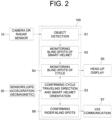
Fig. 2 is a drawing schematically illustrating a blind-spot monitoring method for monitoring the blind spots of the cycle using the smart helmet wearable by the rider of the cycle in accordance with one example embodiment of the present disclosure. -
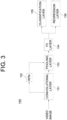
Fig. 3 is a drawing schematically illustrating an object detector for detecting one or more objects from at least one video image in a method for monitoring the blind spots of the cycle using the smart helmet wearable by the rider of the cycle in accordance with one example embodiment of the present disclosure. -
Fig. 4 is a drawing schematically illustrating a process of monitoring the blind spots of the cycle in the method for monitoring the blind spots of the cycle using the smart helmet wearable by the rider of the cycle in accordance with one example embodiment of the present disclosure. -
Fig. 5 is a drawing schematically illustrating a process of traveling the cycle and its nearby vehicles in the method for monitoring the blind spots of the cycle using the smart helmet wearable by the rider of the cycle in accordance with one example embodiment of the present disclosure. -
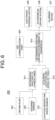
Fig. 6 is a drawing schematically illustrating an operation of an autonomous vehicle traveling by referring to information, on the blind spots of the cycle, from the smart helmet in the method for monitoring the blind spots of the cycle using the smart helmet wearable by the rider of the cycle in accordance with one example of the present disclosure. - Detailed explanation on the present disclosure to be made below refer to attached drawings and diagrams illustrated as specific embodiment examples under which the present disclosure may be implemented to make clear of purposes, technical solutions, and advantages of the present disclosure. These embodiments are described in sufficient detail to enable those skilled in the art to practice the invention.
- Besides, in the detailed description and claims of the present disclosure, a term "include" and its variations are not intended to exclude other technical features, additions, components or steps. Other objects, benefits and features of the present disclosure will be revealed to one skilled in the art, partially from the specification and partially from the implementation of the present disclosure. The following examples and drawings will be provided as examples but they are not intended to limit the present disclosure.
- Moreover, the present disclosure covers all possible combinations of example embodiments indicated in this specification. It is to be understood that the various embodiments of the present disclosure, although different, are not necessarily mutually exclusive. For example, a particular feature, structure, or characteristic described herein in connection with one embodiment may be implemented within other embodiments without departing from the spirit and scope of the present disclosure. In addition, it is to be understood that the position or arrangement of individual elements within each disclosed embodiment may be modified without departing from the spirit and scope of the present disclosure. The following detailed description is, therefore, not to be taken in a limiting sense, and the scope of the present disclosure is defined only by the appended claims, appropriately interpreted, along with the full range of equivalents to which the claims are entitled. In the drawings, similar reference numerals refer to the same or similar functionality throughout the several aspects.
- The headings and abstract of the present disclosure provided herein are for convenience only and do not limit or interpret the scope or meaning of the embodiments.
- To allow those skilled in the art to carry out the present disclosure easily, the example embodiments of the present disclosure by referring to attached diagrams will be explained in detail as shown below.
-
Fig. 1 is a drawing schematically illustrating a blind-spot monitoring device for monitoring one or more blind spots of a cycle using a smart helmet of a rider of the cycle in accordance with one example embodiment of the present disclosure. By referring toFig. 1 , the blind-spot monitoring device 100 includes amemory 110 for storing instructions to monitor the blind spots of the cycle by referring to sensor information acquired from one or more sensors installed on the smart helmet worn by the rider of the cycle, and aprocessor 120 for performing processes to monitor the blind spots of the cycle by referring to the sensor information acquired from the sensors installed on the smart helmet according to the instructions in thememory 110. Throughout the present disclosure, the cycle may include a unicycle, a bicycle, a tricycle, a two-wheeled motorcycle, a one-wheeled or three-wheeled motor vehicle, etc. - Specifically, the blind-
spot monitoring device 100 may typically achieve a desired system performance by using combinations of at least one computing device and at least one computer software, e.g., a computer processor, a memory, a storage, an input device, an output device, or any other conventional computing components, an electronic communication device such as a router or a switch, an electronic information storage system such as a network-attached storage (NAS) device and a storage area network (SAN) as the computing device and any instructions that allow the computing device to function in a specific way as the computer software. - The processor of the computing device may include hardware configuration of MPU (Micro Processing Unit) or CPU (Central Processing Unit), cache memory, data bus, etc. Additionally, the computing device may further include OS and software configuration of applications that achieve specific purposes.
- However, such description of the computing device does not exclude an integrated device including any combination of a processor, a memory, a medium, or any other computing components for implementing the present disclosure.
- A method for monitoring the blind spots of the cycle by referring to the sensor information acquired from the sensors installed on the smart helmet by using the blind-
spot monitoring device 100 in accordance with one example embodiment of the present disclosure is described by referring toFig. 2 as follows. - First, if at least one video image of one or more 1-st blind spots is acquired from at least one camera or at least one
radar sensor 10 installed on the smart helmet worn by the rider, the blind-spot monitoring device 100 performs a process of instructing an object detector to detect one or more objects on the video image, at a step of S1. Herein, the radar sensor may include a LiDAR sensor, a laser sensor, an ultrasonic sensor, etc., and may include any sensors capable of scanning their surrounding environment and acquiring images corresponding to the surrounding environment. - As one example, by referring to
Fig. 3 , the blind-spot monitoring device 100 transmits the video image to theobject detector 150. Then, theobject detector 150 may input the video image into aconvolutional layer 151, to thereby allow theconvolutional layer 151 to apply its at least one convolution operation to the video image and thus to generate at least one feature map. And, theobject detector 150 may input the feature map into aregion proposal network 152, to thereby allow theregion proposal network 152 to output one or more proposal boxes corresponding to one or more objects on the feature map. Thereafter, theobject detector 150 may input the feature map into apooling layer 153, to thereby allow thepooling layer 153 to output at least one feature vector by applying its pooling operation to one or more regions, corresponding to the proposal boxes, on the feature map. And, theobject detector 150 may input the feature vector into a fully connectedlayer 154, to thereby allow the fully connectedlayer 154 to apply its fully-connected operation to the feature vector, and may input at least one output from the fully connectedlayer 154 respectively into aclassification layer 155 and aregression layer 156, to thereby allow theclassification layer 155 and theregression layer 156 to respectively generate class information and regression information on each of the objects corresponding to each of the proposal boxes, and as a result, may detect the objects on the video image. - Herein, the object detector may have been learned by a learning device.
- That is, the learning device may input at least one training image into the
convolutional layer 151, to thereby allow theconvolutional layer 151 to generate at least one feature map for training by applying its at least one convolution operation to the training image, and may input the feature map for training into theregion proposal network 152, to thereby allow theregion proposal network 152 to output one or more proposal boxes for training, corresponding to one or more objects for training, on the feature map for training. And, the learning device may input the feature map for training into thepooling layer 153, to thereby allow thepooling layer 153 to generate at least one feature vector for training by applying its pooling operation to one or more regions, corresponding to the proposal boxes for training, on the feature map for training, and may input the feature vector for training into the fully connectedlayer 154, to thereby allow the fully connectedlayer 154 to apply its fully-connected operation to the feature vector for training. Thereafter, the learning device may input at least one output for training from the fully connectedlayer 154 respectively into theclassification layer 155 and theregression layer 156, to thereby allow theclassification layer 155 and theregression layer 156 to respectively generate class information for training and regression information for training on each of one or more objects for training corresponding to each of the proposal boxes for training. And, the learning device may allow a loss layer to calculate one or more losses by referring to the class information for training and the regression information for training and their respective corresponding GTs, and may update at least one parameter of at least one of the fully connectedlayer 154 and theconvolutional layer 151 via backpropagation using the losses such that the losses are minimized. And, as a result of repeating the above processes, the learning device may learn the object detector. - Next, the blind-
spot monitoring device 100 performs a process of confirming one or more 1-st objects, located in the 1-st blind spots, among the objects detected by the object detector, at a step of S2. - Herein, the 1-st blind spots are the blind spots corresponding to the smart helmet, and may be areas, within a preset distance from the smart helmet, that cannot be visually perceived by the rider.
- Next, if the sensor information is acquired from at least part of the
sensors 20, for example, a GPS sensor, an acceleration sensor, and a geomagnetic sensor, installed on the smart helmet, then the blind-spot monitoring device 100 confirms a smart helmet orientation and a cycle traveling direction at a step of S3, by using the sensor information from at least part of the GPS sensor, the acceleration sensor, and the geomagnetic sensor. - And, the blind-
spot monitoring device 100 performs a process of confirming one or more 2-nd objects, located in one or more 2-nd blind spots corresponding to the cycle, among the 1-st objects, by referring to the smart helmet orientation and the cycle traveling direction at a step of S4. Herein, the 2-nd blind spots are areas near the cycle that cannot be visually perceived by the rider. - That is, the blind-
spot monitoring device 100 performs a process of calculating at least one angular difference between the smart helmet orientation and the cycle traveling direction, a process of converting one or more 1-st locations of the 1-st objects into one or more relative locations corresponding to the cycle traveling direction by using the angular difference, and a process of determining at least part of the 1-st objects, corresponding to at least part of the relative locations matching the 2-nd blind spots, as the 2-nd objects. - As one example, by referring to
Fig. 4 , one ormore sensing angles 4 of the camera or the radar sensor installed on thesmart helmet 2 worn by the rider of thecycle 1 may correspond to the blind spots of the smart helmet, that is, one or more rear areas of the smart helmet, and theblind spots 5 of thecycle 1 are one or more preset areas set as areas where the rider cannot perceive visually depending on a traveling direction of thecycle 1. - Herein, the smart helmet orientation of the
smart helmet 2 may be changed by the rider, and in such a case, the 1-st objects located in the 1-st blind spots, which are the blind spots of the smart helmet detected by the object detector, may not be the objects detected from the 2-nd blind spots which are the blind spots of the cycle. - Therefore, the blind-
spot monitoring device 100 determines an angle between the smart helmet orientation RD and the cycle traveling direction BD on a basis of thesmart helmet 2, converts the 1-st locations of the 1-st objects into the relative locations on a basis of the cycle traveling direction BD by referring to the determined angle, and determines at least part of the 1-st objects, whose relative locations are in the 2-ndblind spots 5, as the 2-nd objects, to thereby detect the objects located in theblind spots 5 of the cycle. - Next, the blind-
spot monitoring device 100 performs a process of displaying the 2-nd objects, at a step of S5, located in the 2-nd blind spots, which are the blind spots of the cycle, via a head-up display installed on the smart helmet, or a process of sounding an alarm representing that the 2-nd objects are located in the 2-nd blind spots via at least one speaker installed on the smart helmet, to thereby allow the rider to safely drive the cycle by perceiving that the objects, that is, one or more pedestrians, one or more vehicles, or one or more other cycles, are located in the blind spots of the cycle. - Also, at a same time, the blind-
spot monitoring device 100 may confirm one or more rider blind spots at a step of S6 by referring to a viewing angle of the rider wearing the smart helmet and the sensing angles of the radar sensor or the camera taking the video image. - That is, by referring to
Fig. 4 again, the riderblind spots 6 may be determined, which are out of ranges of the sensing angles 4 of the camera or the radar sensor installed on the smart helmet and theviewing angle 3 of the rider wearing the smart helmet. - Therefore, the blind-
spot monitoring device 100 may transmit, at a step of S7, (i) rider blind-spot information on the rider blind spots acquired by referring to the viewing angle of the rider wearing the smart helmet and the sensing angles of the camera taking the video image or the radar sensor, and (ii) a cycle location, a cycle traveling direction, and a cycle traveling speed acquired by referring to the sensor information from the smart helmet, to one or more nearby vehicles and one or more nearby smart helmets of one or more nearby cycles. Herein, the blind-spot monitoring device 100 may transmit the rider blind-spot information, the cycle location, the cycle traveling direction, and the cycle traveling speed over V2X (vehicle to everything) communication. - Then, a specific nearby vehicle located in one of the rider blind spots may alert a specific nearby driver of the specific nearby vehicle using a probability of a traffic accident between the specific nearby vehicle and the cycle, where the probability may be determined by referring to (i) a vehicle location, a vehicle traveling direction, and a vehicle traveling speed acquired from the sensor information of the specific nearby vehicle and (ii) the cycle location, the cycle traveling direction, and the cycle traveling speed acquired from the blind-
spot monitoring device 100. Also, at least one specific nearby smart helmet, corresponding to at least one specific nearby cycle located in the rider blind spots, among the nearby smart helmets, may determine a possibility of a traffic accident between the specific nearby cycle and the cycle by referring to (i) a nearby cycle location, a nearby cycle traveling direction, and a nearby cycle traveling speed acquired from sensor information of the specific nearby smart helmet and (ii) the cycle location, the cycle traveling direction, and the cycle traveling speed acquired from the blind-spot monitoring device 100, and may thus alert at least one specific nearby rider corresponding to the specific nearby cycle. - Herein, if the specific nearby driver of the specific nearby vehicle located in the rider blind spots operates a steering wheel of the specific nearby vehicle to move into a nearby front area of the cycle by referring to (i) the vehicle location, the vehicle traveling direction, and the vehicle traveling speed acquired from sensor information of the specific nearby vehicle and (ii) the cycle location, the cycle traveling direction, and the cycle traveling speed acquired from the blind-
spot monitoring device 100, the specific nearby vehicle located in the rider blind spots may perform a process of preventing the steering wheel from rotating or of vibrating the steering wheel in order to alert the specific nearby driver. - As one example, by referring to
Fig. 5 , avehicle 30 traveling near thecycle 1 may perform a process of confirming whether thevehicle 30 is located in one of the riderblind spots 6 by referring to the rider blind-spot information received from the blind-spot monitoring device 100, and a process of, if thevehicle 30 is determined as located in said one of the riderblind spots 6, confirming adangerous area 40 having a probability of a traffic accident larger than a preset threshold in case the vehicle traveling direction of thevehicle 30 is changed to pointing to an area where the rider of thecycle 1 is not paying attention, that is, to the nearby front area of the cycle where the rider is not visually observing, and thus preventing the traffic accident between thevehicle 30 and therider 1 by stopping thevehicle 30 from entering thedangerous area 40. - Also, in case that the specific nearby vehicle located in the rider blind spots is an autonomous vehicle, if a driving plan of the autonomous vehicle is determined as representing moving into the nearby front area of the cycle by referring to (i) an autonomous vehicle location, an autonomous vehicle traveling direction, and an autonomous vehicle traveling speed acquired from sensor information of the autonomous vehicle and (ii) the cycle location, the cycle traveling direction, and the cycle traveling speed, then the autonomous vehicle located in the rider blind spots may prevent itself from changing lanes due to the driving plan of the autonomous vehicle.
- As one example, by referring to
Fig. 6 , theautonomous vehicle 200 may determine whether to change the lanes, and if lane-changing is to be performed, may determine a lane-changing direction by referring to thedriving plan 201 and at least one signal from at least onesteering sensor 202 at a step of S11, and while theautonomous vehicle 200 drives itself by referring to the autonomous vehicle location, the autonomous vehicle traveling direction, and the autonomous vehicle traveling speed using the sensor information acquired from at least one location sensor and at least onespeed sensor 203 at a step of S12, if the rider blind-spot information, the cycle location, the cycle traveling direction, and the cycle traveling speed are acquired via aV2x communication part 204, theautonomous vehicle 200 may determine that itself is located in one of the rider blind spots by referring to the rider blind-spot information. - And, if the
autonomous vehicle 200 is determined as located in said one of the rider blind spots, theautonomous vehicle 200 may determine whether a driving environment of theautonomous vehicle 200 is dangerous, at a step of S13. - That is, in case that the driving plan of the autonomous vehicle is determined as representing moving from said one of the rider blind spots into the nearby front area of the cycle by referring to (i) the autonomous vehicle location, the autonomous vehicle traveling direction, and the autonomous vehicle traveling speed acquired from the sensor information of the autonomous vehicle and (ii) the cycle location, the cycle traveling direction, and the cycle traveling speed, then the autonomous vehicle may determine that the probability of the traffic accident is larger than the preset threshold because the rider of the cycle cannot perceive the
autonomous vehicle 100. - Then, the
autonomous vehicle 200 may operate anelectronic steering device 205 to make the steering wheel difficult to move or to vibrate the steering wheel, to thereby allow the driver of theautonomous vehicle 200 to perceive a dangerous situation. Also, theautonomous vehicle 200 may operate anautonomous driving system 206 to stop theautonomous vehicle 200 from changing the lanes toward the cycle, in order to prevent the traffic accident. Also, theautonomous vehicle 200 may operate analarming device 207 to alert the driver of the autonomous vehicle or the rider of the cycle using light, sound, etc., in order to prevent the traffic accident. - The present disclosure as defined in the appended claims has an effect of preventing traffic accidents by allowing the rider of the cycle being driven to perceive surrounding environment of the cycle.
- The present disclosure has another effect of improving a driving quality of the rider by allowing the rider of the cycle to perceive the surrounding environment of the cycle.
- The present disclosure as claimed in
claims 2 and 8 has in addition the effect of allowing the nearby vehicles to safely travel by transmitting information acquired by the rider of the cycle to the nearby vehicles over the V2X communication, and as a result, reducing the traffic accidents on a roadway. - The embodiments of the present disclosure as defined in the appended claims and as further explained above can be implemented in a form of executable program command through a variety of computer means recordable to computer readable media. The computer readable media may include solely or in combination, program commands, data files, and data structures. The program commands recorded to the media may be components specially designed for the present disclosure or may be usable to those skilled in the art. Computer readable media include magnetic media such as hard disk, floppy disk, and magnetic tape, optical media such as CD-ROM and DVD, magneto-optical media such as floptical disk and hardware devices such as ROM, RAM, and flash memory specially designed to store and carry out program commands. Program commands include not only a machine language code made by a complier but also a high level code that can be used by an interpreter etc., which is executed by a computer. The aforementioned hardware device can work as more than a software module to perform the action of the present disclosure and vice versa.
Claims (10)
- A method performed by a blind-spot monitoring device (100) for monitoring at least one blind spot of a cycle (1) using a smart helmet (2) to be used for a rider of the cycle, wherein the at least one blind spot (5) of the cycle (1) is one or more preset areas set as areas where the rider cannot perceive visually depending on a traveling direction of the cycle (1) and the smart helmet having at least one camera (10) or at least one radar installed thereon, the method comprising steps of:(a) if at least one video image of one or more 1-st blind spots corresponding to the smart helmet worn by the rider is acquired from the at least one camera or radar, detecting (S1) by an object detector (150) one or more objects on the video image and confirming (S2) one or more 1-st objects located in the one or more 1-st blind spots among the detected objects; and(b) determining (S3) a smart helmet orientation (RD) and a cycle traveling direction (BD) by using sensor information acquired from at least part of a GPS sensor, an acceleration sensor, and a geomagnetic sensor installed on the smart helmet, confirming (S4) one or more 2-nd objects, among the one or more 1-st objects, located in one or more 2-nd blind spots corresponding to the blind spots (5) of the cycle by referring to the smart helmet orientation and the cycle traveling direction, wherein confirming (S4) one or more 2-nd objects, among the one or more 1-st objects, is performed by:calculating at least one angular difference between the smart helmet orientation (RD) and the cycle traveling direction (BD) converting one or more 1-st locations of the one or more 1-st objects into one or more relative locations corresponding to the cycle traveling direction by using the at least one angular difference, determining at least part of the one or more 1-st objects, corresponding to at least part of the relative locations matching the one or more 2-nd blind spots, as the 2-nd objects, and the method further comprising, subsequent to confirming (S4), the steps ofdisplaying (S5) the 2-nd objects via a head-up display installed on the smart helmet orsounding an alarm representing that the 2-nd objects are located in the one or more 2-nd blind spots via at least one speaker installed on the smart helmet
- The method of Claim 1, wherein the step of (b) (S3) further includes steps of:
(b1) determining (S6) rider blind-spot information on rider blind spots (6) which are out of range of a viewing angle (3) of the rider wearing the smart helmet and out of range of the one or more sensing angles (4) of the at least one radar sensor or the at least one camera installed on the smart helmet taking the video image and transmitting (S7)(i) the rider blind spot information,(ii) the cycle location, the cycle traveling direction (BD), and the cycle traveling speed acquired by referring to the sensor information, to one or more nearby vehicles and one or more nearby smart helmets corresponding to one or more nearby cycles, to thereby perform at least one of processes of(1) allowing at least one specific nearby vehicle, among the nearby vehicles, located in one or more rider blind spots (1-a) to determine a possibility of a traffic accident between the specific nearby vehicle and the cycle by referring to(i) the vehicle location, the vehicle traveling direction, and the vehicle traveling speed acquired from sensor information of the specific nearby vehicle and(ii) the cycle location, the cycle traveling direction, and the cycle traveling speed, and thus (1-b) to give an alarm to at least one specific nearby vehicle and(2) allowing at least one specific nearby smart helmet, corresponding to at least one specific nearby cycle located in the rider blind spots, among the nearby smart helmets (2-a) to determine a possibility of a traffic accident between the specific nearby cycle and the cycle by referring to(i) the nearby cycle location, the nearby cycle traveling direction, and the nearby cycle traveling speed acquired from sensor information of the specific nearby smart helmet and(ii) the cycle location, the cycle traveling direction, and the cycle traveling speed and thus (2-b) to give an alarm to at least one specific nearby rider corresponding to the specific nearby cycle. - The method of Claim 2, wherein, if the specific nearby driver of the specific nearby vehicle (30) located in the rider blind spots (6) operates a steering wheel of the specific nearby vehicle to move into a nearby front area of the cycle (1) by referring to(i) the vehicle location, the vehicle traveling direction, and the vehicle traveling speed acquired from sensor information of the specific nearby vehicle (30) and(ii) the cycle location, the cycle traveling direction, and the cycle traveling speed, the specific nearby vehicle (30) located in the rider blind spots (6) prevents the steering wheel from rotating or vibrates the steering wheel in order to alert the specific nearby driver.
- The method of Claim 2, wherein, in case the specific nearby vehicle located in the rider blind spots (6) is an autonomous vehicle (200), if a driving plan of the autonomous vehicle is determined as representing moving into the nearby front area of the cycle (10) by referring to (i) the autonomous vehicle location, the autonomous vehicle traveling direction, and the autonomous vehicle traveling speed acquired from sensor information of the autonomous vehicle and (ii) the cycle location, the cycle traveling direction, and the cycle traveling speed, the autonomous vehicle located in the rider blind spots prevents itself from changing lanes due to the driving plan.
- The method of Claim 1, wherein, at the step of (a), the blind-spot monitoring device (100) performs a process of transmitting the video image to the object detector (150) to allow the object detector to (i) input the video image into a convolutional layer (151), to thereby allow the convolutional layer to generate at least one feature map by applying convolution operation to the video image, (ii) input the feature map into a region proposal network (152), to thereby allow the region proposal network to generate one or more proposal boxes corresponding to the objects on the feature map, (iii) input the feature map into a pooling layer (153), to thereby allow the pooling layer to generate at least one feature vector by applying pooling operation to one or more regions, corresponding to the proposal boxes, on the feature map, (iv) input the feature vector into a fully connected layer (154), to thereby allow the fully connected layer to apply fully-connected operation to the feature vector, and (v) input an output from the fully connected layer respectively into a classification layer (155) and a regression layer (156), to thereby allow the classification layer and the regression layer to respectively output class information and regression information on each of the objects corresponding to each of the proposal boxes, and thus to detect the objects in the video image.
- The method of Claim 5, wherein the object detector has been learned by a learning device performing (i) a process of inputting a training image into the convolutional layer (151), to thereby allow the convolutional layer to generate a feature map for training by applying convolution operation to the training image, (ii) a process of inputting the feature map for training into the region proposal network (152), to thereby allow the region proposal network to generate one or more proposal boxes for training corresponding to one or more objects for training on the feature map for training, (iii) a process of inputting the feature map for training into the pooling layer (153), to thereby allow the pooling layer to generate a feature vector for training by applying pooling operation to one or more regions, corresponding to the proposal boxes for training, on the feature map for training, (iv) a process of inputting the feature vector for training into the fully connected layer (154), to thereby allow the fully connected layer to apply fully-connected operation to the feature vector for training, (v) a process of inputting at least one output for training from the fully connected layer respectively into the classification layer (155) and the regression layer (156), to thereby allow the classification layer and the regression layer to respectively output class information for training and regression information for training on each of the objects for training corresponding to each of the proposal boxes for training, and (vi) a process of allowing a loss layer to calculate one or more losses by referring to the class information for training, the regression information for training, and their respective corresponding GTs, to thereby update at least one parameter of at least one of the fully connected layer and the convolutional layer by backpropagating the losses such that the losses are minimized.
- A blind-spot monitoring device (100) for monitoring at least one blind spot of a cycle (1) using a smart helmet (2) to be used for a rider of the cycle, wherein the at least one blind spot (5) of the cycle (1) is one or more preset areas set as areas where the rider cannot perceive visually depending on a traveling direction of the cycle (1), the smart helmet having at least one camera (10) or a at least one radar installed thereon, the blind-spot monitoring device comprising:at least one memory (110) that stores instructions; andat least one processor (120) configured to execute the instructions to perform(I) if at least one video image of one or more 1-st blind spots corresponding to the smart helmet worn by the rider is acquired from the at least one camera or radar, a process of instructing (S1) an object detector (150) to detect one or more objects on the video image and a process of confirming (S2) one or more 1-st objects located in the one or more 1-st blind spots among the detected objects, and(II) a process of determining (S3) a smart helmet orientation (RD) and a cycle traveling direction (BD) by referring to sensor information acquired from at least part of a GPS sensor, an acceleration sensor, and a geomagnetic sensor installed on the smart helmet,a process of confirming (S4) one or more 2-nd objects, among the one or more 1-st objects, located in one or more 2-nd blind spots corresponding to the blind spots (5) of the cycle by referring to the smart helmet orientation and the cycle traveling direction, the process of confirming (S4) is performed by: a process of calculating at least one angular difference between the smart helmet orientation (RD) and the cycle traveling direction (BD),a process of converting one or more 1-st locations of the one or more 1-st objects into one or more relative locations corresponding to the cycle traveling direction by using the at least one angular difference, anda process of determining at least part of the 1-st objects, corresponding to at least part of the relative locations matching the one or more 2-nd blind spots, as the 2-nd objects and, subsequent to the process of confirming (S4), a process of displaying (S5) the 2-nd objects via a head-up display installed on the smart helmet or sounding an alarm representing that the one or more 2-nd objects are located in the 2-nd blind spots via at least one speaker installed on the smart helmet.
- The blind-spot monitoring device of Claim 7, wherein the process of (II) further includes:(II-1) a process of determining (S6) rider blind-spot information on rider blind spots (6) which are out of range of a viewing angle (3) of the rider wearing the smart helmet and out of range of one or more sensing angles (4) of the at least one radar sensor or the at least one camera installed on the smart helmet taking the video image and(II-2) a process of transmitting (S7)(i) the rider blind-spot information,(ii) a cycle location, the cycle traveling direction, and a cycle traveling speed acquired by referring to the sensor information, to one or more nearby vehicles (30, 200) and one or more nearby smart helmets corresponding to one or more nearby cycles.
- The blind-spot monitoring device of Claim 7, wherein, at the process of (I), the processor (120) performs a process of transmitting the video image to the object detector (150) to allow the object detector to (i) input the video image into a convolutional layer (151), to thereby allow the convolutional layer to generate at least one feature map by applying convolution operation to the video image, (ii) input the feature map into a region proposal network (152), to thereby allow the region proposal network to generate one or more proposal boxes corresponding to the objects on the feature map, (iii) input the feature map into a pooling layer (153), to thereby allow the pooling layer to generate at least one feature vector by applying pooling operation to one or more regions, corresponding to the proposal boxes, on the feature map, (iv) input the feature vector into a fully connected layer (154), to thereby allow the fully connected layer to apply fully-connected operation to the feature vector, and (v) input an output from the fully connected layer respectively into a classification layer (155) and a regression layer (156), to thereby allow the classification layer and the regression layer to respectively output class information and regression information on each of the objects corresponding to each of the proposal boxes, and thus to detect the objects in the video image.
- The blind-spot monitoring device of Claim 9, wherein the object detector (150) has been learned by a learning device performing (i) a process of inputting a training image into the convolutional layer (151), to thereby allow the convolutional layer to generate a feature map for training by applying convolution operation to the training image, (ii) a process of inputting the feature map for training into the region proposal network (152), to thereby allow the region proposal network to generate one or more proposal boxes for training corresponding to one or more objects for training on the feature map for training, (iii) a process of inputting the feature map for training into the pooling layer (153), to thereby allow the pooling layer to generate a feature vector for training by applying pooling operation to one or more regions, corresponding to the proposal boxes for training, on the feature map for training, (iv) a process of inputting the feature vector for training into the fully connected layer (154), to thereby allow the fully connected layer to apply fully-connected operation to the feature vector for training, (v) a process of inputting at least one output for training from the fully connected layer respectively into the classification layer (155) and the regression layer (156), to thereby allow the classification layer and the regression layer to respectively output class information for training and regression information for training on each of the objects for training corresponding to each of the proposal boxes for training, and (vi) a process of allowing a loss layer to calculate one or more losses by referring to the class information for training, the regression information for training, and their respective corresponding GTs, to thereby update at least one parameter of at least one of the fully connected layer and the convolutional layer by backpropagating the losses such that the losses are minimized.
Applications Claiming Priority (2)
| Application Number | Priority Date | Filing Date | Title |
|---|---|---|---|
| US201962799282P | 2019-01-31 | 2019-01-31 | |
| US16/732,039 US10698222B1 (en) | 2019-01-31 | 2019-12-31 | Method for monitoring blind spot of cycle using smart helmet for cycle rider and blind spot monitoring device using them |
Publications (3)
| Publication Number | Publication Date |
|---|---|
| EP3690859A1 EP3690859A1 (en) | 2020-08-05 |
| EP3690859B1 true EP3690859B1 (en) | 2025-04-23 |
| EP3690859C0 EP3690859C0 (en) | 2025-04-23 |
Family
ID=71125280
Family Applications (1)
| Application Number | Title | Priority Date | Filing Date |
|---|---|---|---|
| EP20153072.2A Active EP3690859B1 (en) | 2019-01-31 | 2020-01-22 | Method for monitoring blind spot of cycle using smart helmet for cycle rider and blind spot monitoring device using them |
Country Status (5)
| Country | Link |
|---|---|
| US (1) | US10698222B1 (en) |
| EP (1) | EP3690859B1 (en) |
| JP (1) | JP6919925B2 (en) |
| KR (1) | KR102325021B1 (en) |
| CN (2) | CN111493443B (en) |
Families Citing this family (8)
| Publication number | Priority date | Publication date | Assignee | Title |
|---|---|---|---|---|
| US10698222B1 (en) * | 2019-01-31 | 2020-06-30 | StradVision, Inc. | Method for monitoring blind spot of cycle using smart helmet for cycle rider and blind spot monitoring device using them |
| EP3745157B1 (en) * | 2019-05-31 | 2023-11-29 | Aptiv Technologies Limited | Method for detecting non-visible vehicles and system thereof |
| CN112026693A (en) * | 2020-08-19 | 2020-12-04 | 山东交通职业学院 | Engineering machinery anti-rollover control system and control method thereof |
| US11462021B2 (en) * | 2021-01-13 | 2022-10-04 | GM Global Technology Operations LLC | Obstacle detection and notification for motorcycles |
| KR20230094290A (en) | 2021-12-21 | 2023-06-28 | 금오공과대학교 산학협력단 | The smart helmet system |
| WO2023149031A1 (en) * | 2022-02-01 | 2023-08-10 | パナソニック インテレクチュアル プロパティ コーポレーション オブ アメリカ | Information notification method, information notification device, and program |
| KR102607080B1 (en) | 2022-04-25 | 2023-11-29 | 충남대학교산학협력단 | Intelligent helmet appratus and method for operation thereof |
| CN115303390B (en) * | 2022-08-30 | 2024-06-21 | 拉扎斯网络科技(上海)有限公司 | Turn signal auxiliary control method, device and system in delivery scene |
Family Cites Families (26)
| Publication number | Priority date | Publication date | Assignee | Title |
|---|---|---|---|---|
| US7049945B2 (en) * | 2000-05-08 | 2006-05-23 | Automotive Technologies International, Inc. | Vehicular blind spot identification and monitoring system |
| GB2386732B (en) * | 2002-03-06 | 2005-07-13 | Antony Gary Ward | Improvements in and relating to motorcycle safety |
| JP3895225B2 (en) * | 2002-07-10 | 2007-03-22 | 本田技研工業株式会社 | Vehicle warning system |
| JP3123844U (en) * | 2006-05-18 | 2006-07-27 | 祥一 君塚 | Rear confirmation system for motorcycles |
| DE102006037731A1 (en) * | 2006-08-11 | 2008-02-14 | Röder, Roland | Monitoring system e.g. for motor vehicle, has central PC module which receives information from several sensors arranged on vehicle and which is connected to storage device |
| JP4948115B2 (en) * | 2006-10-18 | 2012-06-06 | ヤマハ発動機株式会社 | Rear view device |
| EP1974998B1 (en) * | 2007-03-26 | 2011-05-25 | Aisin AW Co., Ltd. | Driving support method and driving support apparatus |
| JP2013011939A (en) * | 2011-06-28 | 2013-01-17 | Mitsubishi Motors Corp | Driving support device |
| US20130311075A1 (en) * | 2012-05-18 | 2013-11-21 | Continental Automotive Systems, Inc. | Motorcycle and helmet providing advance driver assistance |
| US9247779B1 (en) * | 2012-11-08 | 2016-02-02 | Peter Aloumanis | Enhanced global positioning system (GPS) based functionality for helmets |
| US10219571B1 (en) * | 2012-11-08 | 2019-03-05 | Peter Aloumanis | In helmet sensors providing blind spot awareness |
| JP5846109B2 (en) * | 2012-11-20 | 2016-01-20 | 株式会社デンソー | Collision determination device and collision avoidance system |
| US10065562B2 (en) * | 2013-12-31 | 2018-09-04 | International Business Mahcines Corporation | Vehicle collision avoidance |
| FR3024334A1 (en) * | 2014-07-31 | 2016-02-05 | Romain Duflot | HIGH HEAD PROJECTION ACCESSORIES FOR MOTORCYCLE |
| WO2016086230A1 (en) * | 2014-11-28 | 2016-06-02 | Tammam Eric S | Augmented audio enhanced perception system |
| EP3050752A1 (en) * | 2015-01-29 | 2016-08-03 | Application Solutions (Electronics and Vision) Ltd. | Motorcycle rear view cameras |
| US10368602B2 (en) * | 2015-04-27 | 2019-08-06 | Intelligent Cranium Helmets, LLC | Protective helmet |
| JP2017030530A (en) * | 2015-07-31 | 2017-02-09 | スズキ株式会社 | Video display system |
| TWM516332U (en) * | 2015-11-11 | 2016-02-01 | Jarvish Inc | Helmet having auxiliary function for blind spots |
| US10694801B2 (en) * | 2016-09-28 | 2020-06-30 | Bruce Cooke | Electronic motorcycle helmet |
| CN107028274A (en) * | 2017-04-11 | 2017-08-11 | 重庆银钢科技(集团)有限公司 | A kind of helmet and the method that interaction is carried out using the helmet |
| CN207037598U (en) * | 2017-05-31 | 2018-02-23 | 广东南海鹰视通达科技有限公司 | An intelligent display helmet and its display system |
| CN108010383A (en) * | 2017-09-29 | 2018-05-08 | 北京车和家信息技术有限公司 | Blind zone detection method, device, terminal and vehicle based on driving vehicle |
| US9934440B1 (en) * | 2017-10-04 | 2018-04-03 | StradVision, Inc. | Method for monitoring blind spot of monitoring vehicle and blind spot monitor using the same |
| US9947228B1 (en) * | 2017-10-05 | 2018-04-17 | StradVision, Inc. | Method for monitoring blind spot of vehicle and blind spot monitor using the same |
| US10698222B1 (en) * | 2019-01-31 | 2020-06-30 | StradVision, Inc. | Method for monitoring blind spot of cycle using smart helmet for cycle rider and blind spot monitoring device using them |
-
2019
- 2019-12-31 US US16/732,039 patent/US10698222B1/en active Active
-
2020
- 2020-01-13 KR KR1020200004524A patent/KR102325021B1/en active Active
- 2020-01-21 JP JP2020007737A patent/JP6919925B2/en active Active
- 2020-01-22 EP EP20153072.2A patent/EP3690859B1/en active Active
- 2020-01-22 CN CN202010073407.2A patent/CN111493443B/en active Active
- 2020-01-22 CN CN202211056264.XA patent/CN115515106B/en active Active
Also Published As
| Publication number | Publication date |
|---|---|
| CN111493443A (en) | 2020-08-07 |
| CN111493443B (en) | 2022-09-20 |
| JP6919925B2 (en) | 2021-08-18 |
| CN115515106A (en) | 2022-12-23 |
| KR20200096122A (en) | 2020-08-11 |
| EP3690859A1 (en) | 2020-08-05 |
| EP3690859C0 (en) | 2025-04-23 |
| JP2020126629A (en) | 2020-08-20 |
| KR102325021B1 (en) | 2021-11-15 |
| CN115515106B (en) | 2025-07-29 |
| US10698222B1 (en) | 2020-06-30 |
Similar Documents
| Publication | Publication Date | Title |
|---|---|---|
| EP3690859B1 (en) | Method for monitoring blind spot of cycle using smart helmet for cycle rider and blind spot monitoring device using them | |
| US12367749B2 (en) | Active vehicle safety system for cyclists and pedestrians | |
| US12077046B2 (en) | Interactive safety system for vehicles | |
| JP6468454B2 (en) | System and method for processing traffic sound data to provide driver assistance | |
| JP7382327B2 (en) | Information processing device, mobile object, information processing method and program | |
| US12139075B2 (en) | Vehicle with a protective warning system | |
| JP7133086B2 (en) | saddle-riding vehicle | |
| CN106043308A (en) | Method and device for detecting the alertness of a vehicle driver | |
| TWI755869B (en) | Inclined vehicle with FCW control | |
| JP2017027292A (en) | Vehicle control device | |
| WO2015174208A1 (en) | Image-recognition device and method for controlling same | |
| CN107399290A (en) | Safe driving assistant system and its control method | |
| JP2017151963A (en) | Method and device for supporting driver | |
| JP2019185639A (en) | Collision determination device and method | |
| JP2010039933A (en) | Inattentive driving determination device | |
| KR102094405B1 (en) | Method and apparatus for determining an accident using an image | |
| KR20240124570A (en) | Method or apparatus for collision avoidance or impulse reduction | |
| JP7722336B2 (en) | Driving assistance devices | |
| US20240264291A1 (en) | Apparatus and method controlling the same | |
| JP2006331082A (en) | Operation support device for vehicle | |
| CN121459612A (en) | Method and apparatus for processing data associated with a vehicle | |
| KR20140055352A (en) | Apparatus and method for accident information management of vehicle |
Legal Events
| Date | Code | Title | Description |
|---|---|---|---|
| PUAI | Public reference made under article 153(3) epc to a published international application that has entered the european phase |
Free format text: ORIGINAL CODE: 0009012 |
|
| STAA | Information on the status of an ep patent application or granted ep patent |
Free format text: STATUS: REQUEST FOR EXAMINATION WAS MADE |
|
| 17P | Request for examination filed |
Effective date: 20200222 |
|
| AK | Designated contracting states |
Kind code of ref document: A1 Designated state(s): AL AT BE BG CH CY CZ DE DK EE ES FI FR GB GR HR HU IE IS IT LI LT LU LV MC MK MT NL NO PL PT RO RS SE SI SK SM TR |
|
| AX | Request for extension of the european patent |
Extension state: BA ME |
|
| RBV | Designated contracting states (corrected) |
Designated state(s): AL AT BE BG CH CY CZ DE DK EE ES FI FR GB GR HR HU IE IS IT LI LT LU LV MC MK MT NL NO PL PT RO RS SE SI SK SM TR |
|
| STAA | Information on the status of an ep patent application or granted ep patent |
Free format text: STATUS: EXAMINATION IS IN PROGRESS |
|
| 17Q | First examination report despatched |
Effective date: 20220214 |
|
| REG | Reference to a national code |
Ref country code: DE Ref legal event code: R079 Free format text: PREVIOUS MAIN CLASS: G08G0001160000 Ipc: B60W0050140000 Ref country code: DE Ref legal event code: R079 Ref document number: 602020049799 Country of ref document: DE Free format text: PREVIOUS MAIN CLASS: G08G0001160000 Ipc: B60W0050140000 |
|
| GRAP | Despatch of communication of intention to grant a patent |
Free format text: ORIGINAL CODE: EPIDOSNIGR1 |
|
| RIC1 | Information provided on ipc code assigned before grant |
Ipc: G06N 3/045 20230101ALI20241015BHEP Ipc: G06V 20/58 20220101ALI20241015BHEP Ipc: G06V 10/82 20220101ALI20241015BHEP Ipc: G08G 1/0967 20060101ALI20241015BHEP Ipc: G06N 3/084 20230101ALI20241015BHEP Ipc: B60W 50/14 20200101AFI20241015BHEP |
|
| STAA | Information on the status of an ep patent application or granted ep patent |
Free format text: STATUS: GRANT OF PATENT IS INTENDED |
|
| INTG | Intention to grant announced |
Effective date: 20241121 |
|
| GRAS | Grant fee paid |
Free format text: ORIGINAL CODE: EPIDOSNIGR3 |
|
| GRAA | (expected) grant |
Free format text: ORIGINAL CODE: 0009210 |
|
| STAA | Information on the status of an ep patent application or granted ep patent |
Free format text: STATUS: THE PATENT HAS BEEN GRANTED |
|
| AK | Designated contracting states |
Kind code of ref document: B1 Designated state(s): AL AT BE BG CH CY CZ DE DK EE ES FI FR GB GR HR HU IE IS IT LI LT LU LV MC MK MT NL NO PL PT RO RS SE SI SK SM TR |
|
| REG | Reference to a national code |
Ref country code: GB Ref legal event code: FG4D |
|
| REG | Reference to a national code |
Ref country code: CH Ref legal event code: EP |
|
| REG | Reference to a national code |
Ref country code: DE Ref legal event code: R096 Ref document number: 602020049799 Country of ref document: DE |
|
| REG | Reference to a national code |
Ref country code: IE Ref legal event code: FG4D |
|
| U01 | Request for unitary effect filed |
Effective date: 20250523 |
|
| U07 | Unitary effect registered |
Designated state(s): AT BE BG DE DK EE FI FR IT LT LU LV MT NL PT RO SE SI Effective date: 20250704 |
|
| PG25 | Lapsed in a contracting state [announced via postgrant information from national office to epo] |
Ref country code: ES Free format text: LAPSE BECAUSE OF FAILURE TO SUBMIT A TRANSLATION OF THE DESCRIPTION OR TO PAY THE FEE WITHIN THE PRESCRIBED TIME-LIMIT Effective date: 20250423 |
|
| PG25 | Lapsed in a contracting state [announced via postgrant information from national office to epo] |
Ref country code: GR Free format text: LAPSE BECAUSE OF FAILURE TO SUBMIT A TRANSLATION OF THE DESCRIPTION OR TO PAY THE FEE WITHIN THE PRESCRIBED TIME-LIMIT Effective date: 20250724 Ref country code: NO Free format text: LAPSE BECAUSE OF FAILURE TO SUBMIT A TRANSLATION OF THE DESCRIPTION OR TO PAY THE FEE WITHIN THE PRESCRIBED TIME-LIMIT Effective date: 20250723 |
|
| PG25 | Lapsed in a contracting state [announced via postgrant information from national office to epo] |
Ref country code: PL Free format text: LAPSE BECAUSE OF FAILURE TO SUBMIT A TRANSLATION OF THE DESCRIPTION OR TO PAY THE FEE WITHIN THE PRESCRIBED TIME-LIMIT Effective date: 20250423 |
|
| PG25 | Lapsed in a contracting state [announced via postgrant information from national office to epo] |
Ref country code: HR Free format text: LAPSE BECAUSE OF FAILURE TO SUBMIT A TRANSLATION OF THE DESCRIPTION OR TO PAY THE FEE WITHIN THE PRESCRIBED TIME-LIMIT Effective date: 20250423 |
|
| PG25 | Lapsed in a contracting state [announced via postgrant information from national office to epo] |
Ref country code: RS Free format text: LAPSE BECAUSE OF FAILURE TO SUBMIT A TRANSLATION OF THE DESCRIPTION OR TO PAY THE FEE WITHIN THE PRESCRIBED TIME-LIMIT Effective date: 20250723 |
|
| PG25 | Lapsed in a contracting state [announced via postgrant information from national office to epo] |
Ref country code: IS Free format text: LAPSE BECAUSE OF FAILURE TO SUBMIT A TRANSLATION OF THE DESCRIPTION OR TO PAY THE FEE WITHIN THE PRESCRIBED TIME-LIMIT Effective date: 20250823 |
|
| PG25 | Lapsed in a contracting state [announced via postgrant information from national office to epo] |
Ref country code: SM Free format text: LAPSE BECAUSE OF FAILURE TO SUBMIT A TRANSLATION OF THE DESCRIPTION OR TO PAY THE FEE WITHIN THE PRESCRIBED TIME-LIMIT Effective date: 20250423 |
|
| PG25 | Lapsed in a contracting state [announced via postgrant information from national office to epo] |
Ref country code: CZ Free format text: LAPSE BECAUSE OF FAILURE TO SUBMIT A TRANSLATION OF THE DESCRIPTION OR TO PAY THE FEE WITHIN THE PRESCRIBED TIME-LIMIT Effective date: 20250423 |
|
| PG25 | Lapsed in a contracting state [announced via postgrant information from national office to epo] |
Ref country code: SK Free format text: LAPSE BECAUSE OF FAILURE TO SUBMIT A TRANSLATION OF THE DESCRIPTION OR TO PAY THE FEE WITHIN THE PRESCRIBED TIME-LIMIT Effective date: 20250423 |
|
| PLBE | No opposition filed within time limit |
Free format text: ORIGINAL CODE: 0009261 |
|
| STAA | Information on the status of an ep patent application or granted ep patent |
Free format text: STATUS: NO OPPOSITION FILED WITHIN TIME LIMIT |
|
| REG | Reference to a national code |
Ref country code: CH Ref legal event code: L10 Free format text: ST27 STATUS EVENT CODE: U-0-0-L10-L00 (AS PROVIDED BY THE NATIONAL OFFICE) Effective date: 20260304 |
|
| U20 | Renewal fee for the european patent with unitary effect paid |
Year of fee payment: 7 Effective date: 20260129 |
|
| 26N | No opposition filed |
Effective date: 20260126 |