EP3690847A1 - Lift-up determining device and lift-up determining method - Google Patents
Lift-up determining device and lift-up determining method Download PDFInfo
- Publication number
- EP3690847A1 EP3690847A1 EP18861591.8A EP18861591A EP3690847A1 EP 3690847 A1 EP3690847 A1 EP 3690847A1 EP 18861591 A EP18861591 A EP 18861591A EP 3690847 A1 EP3690847 A1 EP 3690847A1
- Authority
- EP
- European Patent Office
- Prior art keywords
- tire
- determination unit
- lift
- determining device
- vehicle
- Prior art date
- Legal status (The legal status is an assumption and is not a legal conclusion. Google has not performed a legal analysis and makes no representation as to the accuracy of the status listed.)
- Granted
Links
Images







Classifications
-
- G—PHYSICS
- G06—COMPUTING OR CALCULATING; COUNTING
- G06T—IMAGE DATA PROCESSING OR GENERATION, IN GENERAL
- G06T7/00—Image analysis
- G06T7/70—Determining position or orientation of objects or cameras
- G06T7/73—Determining position or orientation of objects or cameras using feature-based methods
-
- G—PHYSICS
- G06—COMPUTING OR CALCULATING; COUNTING
- G06T—IMAGE DATA PROCESSING OR GENERATION, IN GENERAL
- G06T7/00—Image analysis
- G06T7/20—Analysis of motion
-
- G—PHYSICS
- G06—COMPUTING OR CALCULATING; COUNTING
- G06T—IMAGE DATA PROCESSING OR GENERATION, IN GENERAL
- G06T7/00—Image analysis
- G06T7/70—Determining position or orientation of objects or cameras
-
- G—PHYSICS
- G06—COMPUTING OR CALCULATING; COUNTING
- G06T—IMAGE DATA PROCESSING OR GENERATION, IN GENERAL
- G06T7/00—Image analysis
- G06T7/97—Determining parameters from multiple pictures
-
- G—PHYSICS
- G06—COMPUTING OR CALCULATING; COUNTING
- G06V—IMAGE OR VIDEO RECOGNITION OR UNDERSTANDING
- G06V10/00—Arrangements for image or video recognition or understanding
- G06V10/70—Arrangements for image or video recognition or understanding using pattern recognition or machine learning
- G06V10/768—Arrangements for image or video recognition or understanding using pattern recognition or machine learning using context analysis, e.g. recognition aided by known co-occurring patterns
-
- G—PHYSICS
- G06—COMPUTING OR CALCULATING; COUNTING
- G06V—IMAGE OR VIDEO RECOGNITION OR UNDERSTANDING
- G06V20/00—Scenes; Scene-specific elements
- G06V20/10—Terrestrial scenes
-
- G—PHYSICS
- G06—COMPUTING OR CALCULATING; COUNTING
- G06V—IMAGE OR VIDEO RECOGNITION OR UNDERSTANDING
- G06V20/00—Scenes; Scene-specific elements
- G06V20/50—Context or environment of the image
- G06V20/52—Surveillance or monitoring of activities, e.g. for recognising suspicious objects
- G06V20/54—Surveillance or monitoring of activities, e.g. for recognising suspicious objects of traffic, e.g. cars on the road, trains or boats
-
- G—PHYSICS
- G06—COMPUTING OR CALCULATING; COUNTING
- G06V—IMAGE OR VIDEO RECOGNITION OR UNDERSTANDING
- G06V40/00—Recognition of biometric, human-related or animal-related patterns in image or video data
- G06V40/20—Movements or behaviour, e.g. gesture recognition
-
- G—PHYSICS
- G08—SIGNALLING
- G08G—TRAFFIC CONTROL SYSTEMS
- G08G1/00—Traffic control systems for road vehicles
- G08G1/01—Detecting movement of traffic to be counted or controlled
- G08G1/015—Detecting movement of traffic to be counted or controlled with provision for distinguishing between two or more types of vehicles, e.g. between motor-cars and cycles
-
- G—PHYSICS
- G08—SIGNALLING
- G08G—TRAFFIC CONTROL SYSTEMS
- G08G1/00—Traffic control systems for road vehicles
- G08G1/01—Detecting movement of traffic to be counted or controlled
- G08G1/04—Detecting movement of traffic to be counted or controlled using optical or ultrasonic detectors
-
- G—PHYSICS
- G06—COMPUTING OR CALCULATING; COUNTING
- G06T—IMAGE DATA PROCESSING OR GENERATION, IN GENERAL
- G06T2207/00—Indexing scheme for image analysis or image enhancement
- G06T2207/30—Subject of image; Context of image processing
- G06T2207/30248—Vehicle exterior or interior
-
- G—PHYSICS
- G06—COMPUTING OR CALCULATING; COUNTING
- G06V—IMAGE OR VIDEO RECOGNITION OR UNDERSTANDING
- G06V2201/00—Indexing scheme relating to image or video recognition or understanding
- G06V2201/08—Detecting or categorising vehicles
Definitions
- the present disclosure relates to a lift-up determining device that determines whether one or more axles of a vehicle are lifted up.
- the lift axle mechanism brings up, in other words, lifts up at least one axle such that tires on the axle are not in contact with the ground.
- toll roads have a toll system in which a toll is different depending on the number of axles whose tires are in contact with the ground.
- Such toll roads are desired to be installed with a lift-up determining device that determines whether an axle of a vehicle running on the toll road is lifted up.
- an axle number detection device is described in, for example, PTL 1.
- the present disclosure is made in view of the above issues, and an object of the present disclosure is to provide a lift-up determining device with which the cost required for installation, repair, or removal of the lift-up determining device can be made lower than before, and to provide a lift-up determining method having such features.
- a lift-up determining device includes a detector and a determination unit.
- the detector acquires a captured image including a tire on an axle of a vehicle and detects the tire from the captured image.
- the determination unit determines whether the axle is lifted up, based on the detection result of the detector.
- a lift-up determining method acquires a captured image including a tire of an axle of a vehicle, detects the tire from the captured image, and determines whether the axle is lifted up.
- a lift-up determining device includes a detector and a determination unit.
- the detector acquires a captured image including a tire on an axle of a vehicle and detects the tire from the captured image.
- the determination unit determines whether the axle is lifted up, based on the detection result of the detector.
- this lift-up determining device can determine in a non-contact manner whether at least one axle of a vehicle is lifted up.
- this lift-up determining device when installed, it is not necessary to bury, in a traveling road or the like, a sensor and other components required to determine whether an axle is lifted up.
- the above lift-up determining device may further include a position determination unit. If the tire is a middle tire located between a front-most front wheel tire on the vehicle and a rear-most rear wheel tire of the vehicle, the position determination unit may determine whether a lowest point of the middle tire is apart by greater than or equal to a predetermined value on an upper side of the vehicle from a baseline that extends, from a lowest point of the rear wheel tire, in a traveling direction of the vehicle. The determination unit may determine that the axle is lifted up when the position determination unit determines that the lowest point of the middle tire is apart by greater than or equal to the predetermined value on the upper side of the vehicle from the baseline.
- the above lift-up determining device may further include a calculator.
- the calculator may calculate, from the captured image, a straight line connecting the lowest point of the front wheel tire and the lowest point of the rear wheel tire.
- the position determination unit may use the straight line calculated by the calculator as the baseline.
- the above lift-up determining device may further include a rotation determination unit.
- the rotation determination unit may determine whether the tire detected by the detector is rotating, based on the captured image. If the rotation determination unit determines that the tire is not rotating, the determination unit may determine that the axle is lifted up.
- the rotation determination unit may determine whether the tire is rotating, based on a frequency component of a plurality of pixels included in an area of the tire.
- the rotation determination unit may determine whether the tire detected by the detector is rotating, based on a result of comparison between the frequency component and a frequency component of a plurality of pixels included in an area of the front-most front wheel tire of the vehicle.
- the rotation determination unit may determine whether the tire detected by the detector is rotating, based on a result of comparison between the frequency component and a frequency component of a plurality of pixels included in an area of the rear-most rear wheel tire of the vehicle.
- the detector may acquire another captured image including a tire and may detect the tire from the another captured image.
- the rotation determination unit may calculate a rotation amount of the tire based on the captured image and the another captured image and may determine whether the tire is rotating, based on the calculated rotation amount.
- the above lift-up determining device may further include a deflection determination unit.
- the deflection determination unit may determine, based on the captured image, whether a local region of a road surface located directly under the lowest point of the tire detected by the detector is deflected by greater than or equal to a predetermined value. If the deflection determination unit determines that the local region is not deflected by greater than or equal to the predetermined value, the determination unit may determine that the axle is lifted up.
- the above lift-up determining device may further include a position determination unit, a rotation determination unit, and a deflection determination unit. If the tire is a middle tire located between a front-most front wheel tire on the vehicle and a rear-most rear wheel tire of the vehicle, the position determination unit may determine whether a lowest point of the middle tire is apart by greater than or equal to a predetermined value on an upper side of the vehicle from a baseline that extends, from a lowest point of the rear wheel tire, in a traveling direction of the vehicle. The rotation determination unit may determine whether the tire detected by the detector is rotating, based on the captured image.
- the deflection determination unit may determine, based on the captured image, whether a local region of a road surface located directly under the lowest point of the tire detected by the detector is deflected by greater than or equal to a predetermined value.
- the determination unit may determine whether the axle is lifted up, based on the determination result of the position determination unit, the determination result of the rotation determination unit, and the determination result of the deflection determination unit.
- a lift-up determining method acquires a captured image including a tire on an axle of a vehicle, detects the tire from the captured image, and determines whether the axle is lifted up.
- a lift-up determining device using the lift-up determining method can determine in a non-contact manner whether at least one axle of a vehicle is lifted up.
- CD-ROM compact disc read only memory
- a lift-up determining device that determines whether at least one axle of a vehicle is lifted up.
- This lift-up determining device acquires from the outside a captured image of a vehicle including a tire. Then, the lift-up determining device determines whether at least one axle of the vehicle is lifted up, based on the acquired captured image.
- FIG. 1 is a schematic diagram showing an example when lift-up determining device 10 according to the first exemplary embodiment determines whether at least one axle of vehicle 40 travelling on traveling road 30 is lifted up.
- lift-up determining device 10 is connected to image capturing device 20 that captures one or more captured images including one or more tires of vehicle 40 running on traveling road 30
- image capturing device 20 that captures one or more captured images including one or more tires of vehicle 40 running on traveling road 30
- one or more captured images taken by image capturing device 20 are output from image capturing device 20.
- FIG. 2 is a block diagram showing a configuration of lift-up determining device 10.
- lift-up determining device 10 is configured to include detector 11, calculator 12, position determination unit 13, and determination unit 14.
- Lift-up determining device 10 is implemented, for example, such that, in a computer (not shown) including a microprocessor (not shown) and a memory (not shown), the microprocessor executes a program stored in the memory.
- Detector 11 acquires one or more captured images including a tire on an axle of one vehicle, from image capturing device 20. Then, detector 11 detects one or more tires from the acquired one or more captured images.
- Detector 11 may detect a tire by, for example, previously machine learning on identification of tire. Further, detector 11 may detect a tire by, for example, using a template matching method.
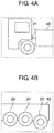
- FIGS. 3 , 4A, and 4B are schematic diagrams each showing an example of a captured image acquired by detector 11.
- Detector 11 may acquire, from image capturing device 20, one captured image including front wheel tire 21 on a front-most axle of vehicle 40 and rear wheel tire 22 on a rear-most axle of vehicle 40, for example, as shown in FIG. 3 .
- detector 11 may acquire, from image capturing device 20, a plurality of captured images each of which does not include front wheel tire 21 and rear wheel tire 22 of vehicle 40 at the same time, for example, as shown in FIGS. 4A and 4B .
- Calculator 12 calculates a baseline that extends from a lowest point of rear wheel tire 22 in a traveling direction of vehicle 40, from the one or more captured images acquired by detector 11.
- calculator 12 may calculate, as the above baseline, a straight line connecting a lowest point of front wheel tire 21 and the lowest point of rear wheel tire 22 by using a detection result of detector 11.
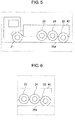
- FIG. 5 is a schematic diagram showing baseline 25a calculated by calculator 12 in the above example.
- calculator 12 may calculates, as the above baseline, a straight line that extends from the lowest point of rear wheel tire 22 in the traveling direction of a driving lane on which vehicle 40 is running, by using a detection result of detector 11.
- FIG. 6 is a schematic diagram showing baseline 25b calculated by calculator 12 in the above example.
- calculator 12 may compose these plurality of captured images to generate one composite image including front wheel tire 21 and rear wheel tire 22. Then, calculator 12 may calculate, as the above baseline, a straight line connecting the lowest point of front wheel tire 21 and the lowest point of rear wheel tire 22 by using the detection result of detector 11 from the composed composite image.
- Position determination unit 13 determines whether the lowest point of a tire that is included in the one or more tires detected by detector 11 and is other than front wheel tire 21 or rear wheel tire 22 of vehicle 40 (in this case, the tire is, for example, tires 23 and 24 in FIGS. 3 , 4B , 5, and 6 , and hereinafter, referred to as "middle tire") is apart by greater than or equal to a predetermined value on the upper side of vehicle 40 from the baseline (in this case, the baseline is, for example, baseline 25a in FIG. 5 or baseline 25b in FIG. 6 ) calculated by the calculator.
- the above predetermined value may be any value as long as the value indicates that a tire on a middle axle is lifted up by a lift axle mechanism to such an extent that the tire is not in contact with the ground.
- the above predetermined value may be, for example, a predetermined pixel number of the captured image (for example, 100 pixels) or may be, for example, a predetermined distance converted to the real space (for example, 10 cm).
- Determination unit 14 determines, based on the detection result of detector 11, whether at least one axle of vehicle 40 is lifted up.
- determination unit 14 positively performs the above determination, which is to be made by determination unit 14, if there is a tire that is positively determined by position determination unit 13.
- a middle tire on a middle axle other than the front-most axle and the rear-most axle of the vehicle is an object to be lifted up. Therefore, in the target vehicle, if the lowest point of the middle tire on the middle axle is apart by greater than or equal to the above predetermined value on the upper side of the vehicle from the baseline that extends from the lowest point of the rear wheel tire on the rear-most axle of the vehicle in the traveling direction of the vehicle, it means that the middle axle of the vehicle is lifted up.
- determination unit 14 negatively performs the above determination, which is to be made by determination unit 14, if there is no middle tire that is positively determined by position determination unit 13.
- determination unit 14 outputs the determination result to the outside.
- Lift-up determining device 10 performs a first determination process as a characteristic operation of lift-up determining device 10.
- the first determination process is a process that determines, if image capturing device 20 has output one or more captured images including one or more tires of one vehicle, whether at least one or more axles of the vehicle are lifted up.
- FIG. 7 is a flowchart of the first determination process.
- the first determination process is started upon output of one or more captured images including one or more tires of one vehicle 40 from image capturing device 20 to lift-up determining device 10.
- detector 11 acquires from image capturing device 20 one or more captured images including one or more tires of one vehicle 40 (step S10).
- detector 11 detects one or more tires from the acquired one or more captured images (step S20).
- calculator 12 calculates a baseline that extends from the lowest point of rear wheel tire 22 of vehicle 40 in a traveling direction of vehicle 40, from the one or more captured images acquired by detector 11 (step S30).
- position determination unit 13 determines, regarding the middle tire on the middle axle of the one or more tires detected by detector 11, whether the lowest point of the middle tire is apart by greater than or equal to a predetermined value on the upper side of vehicle 40 from the baseline calculated by calculator 12 (step S40).
- determination unit 14 checks whether there is a tire that was positively determined by position determination unit 13 in the process of step S40 (step S50).
- step S50 if there is a tire that was positively determined by position determination unit 13 (step S50: Yes), determination unit 14 determines that at least one axle of vehicle 40 is lifted up (step S60).
- step S50 if there is no tire that was positively determined by position determination unit 13 (step S50: No), determination unit 14 determines that no axle of vehicle 40 is lifted up (step S70).
- determination unit 14 When the process of step S60 or step S70 is finished, determination unit 14 outputs a determination result to the outside (step S80).
- step S80 When the process of step S80 is finished, lift-up determining device 10 finishes the first determination process.
- lift-up determining device 10 determines, from a captured image taken by external image capturing device 20, whether there is a tire on a middle axle lifted up to such an extent that the tire is not in contact with the ground. Then, lift-up determining device 10 determines whether at least one axle of the vehicle is lifted up, based on this determination result.
- lift-up determining device 10 can determine in a non-contact manner whether an axle is lifted up.
- lift-up determining device 10 when lift-up determining device 10 is installed, it is not necessary to bury, in a traveling road or the like, a sensor and other components required to determine whether an axle is lifted up.
- this lift-up determining device 10 it is possible to make a cost required for installation, repair, or removal of the lift-up determining device lower than before.
- lift-up determining device 10a that is configured such that a part of the configuration of lift-up determining device 10 according to the first exemplary embodiment is modified.
- Lift-up determining device 10 is an example of a configuration in which, by determining from a captured image whether there is a middle tire on a middle axle lifted up to such an extent that the tire is not in contact with the ground, it is determined whether an axle of a target vehicle is lifted up.
- lift-up determining device 10a is an example of a configuration in which, by determining from a captured image whether there is a tire that is not rotating to such an extent that the vehicle runs, it is determined whether an axle of a target vehicle is lifted up.
- lift-up determining device 10a will be described mainly on a difference from lift-up determining device 10 according to the first exemplary embodiment.
- FIG. 8 is a block diagram showing a configuration of lift-up determining device 10a according to the second exemplary embodiment.
- lift-up determining device 10a is configured such that, with respect to lift-up determining device 10 according to the first exemplary embodiment, calculator 12 and position determination unit 13 are removed, determination unit 14 is changed to determination unit 14a, and rotation determination unit 15 is added.
- Rotation determination unit 15 determines, based on one or more captured images acquired by detector 11, whether at least one tire of one or more tires detected by detector 11 is rotating.
- rotation determination unit 15 determines whether the tire is rotating, based on a frequency component of a plurality of pixels included in an area of the above at least one tire.
- Rotation determination unit 15 uses this phenomenon to determine whether the tire is rotating.
- rotation determination unit 15 may determine that the second tire is not rotating.
- middle tire 23, 24 on the middle axle of vehicle 40 if a proportion of a high frequency component in a frequency component of pixel values of a plurality of pixels in an area of the tire is smaller, by greater than or equal to a second predetermined value, than a high frequency component in a frequency component of pixel values of a plurality of pixels included in an area of front wheel tire 21 or rear wheel tire 22 of vehicle 40, rotation determination unit 15 may determine that such middle tire 23, 24 is not rotating.
- rotation determination unit 15 may determine whether middle tire 23 detected by detector 11 is rotating, based on a result of a comparison of a frequency component of a plurality of pixels included in the area of middle tire 23 of vehicle 40 and a frequency component of a plurality of pixels included in the area of front wheel tire 21.
- rotation determination unit 15 may determine whether middle tire 23 detected by detector 11 is rotating, based on a result of a comparison of a frequency component of a plurality of pixels included in the area of middle tire 23 of vehicle 40 and a frequency component of a plurality of pixels included in the area of rear wheel tire 22.
- rotation determination unit 15 may determine whether middle tire 23 is rotating, based on a result of a comparison of a proportion of a high frequency component of a frequency component of middle tire 23 and a proportion of a high frequency component of a frequency component of front wheel tire 21 or rear wheel tire 22.
- rotation determination unit 15 may determine that the tire is not rotating.
- the first predetermined value, the second predetermined value, and the third predetermined value may be any value, as long as the values each make it possible to distinguish between a tire rotating to such an extent that the vehicle runs and a tire not rotating to such an extent that the vehicle runs. Further, the above predetermined values may change depending on an imaging condition (such as a shutter speed) when a captured image is taken by image capturing device 20.
- an imaging condition such as a shutter speed
- Determination unit 14a determines, based on the detection result of detector 11, whether at least one axle of vehicle 40 is lifted up.
- determination unit 14a negatively performs the above determination, which is to be made by determination unit 14a, if there is a tire that is positively determined by rotation determination unit 15.
- a tire on a lifted-up axle does not rotate while the vehicle is running. Therefore, if a running vehicle has a non-rotating tire, it means that an axle of the vehicle to which the tire is attached is lifted up.
- determination unit 14a negatively performs the above determination, which is to be made by determination unit 14a, if there is no middle tire that is negatively determined by rotation determination unit 15.
- determination unit 14a outputs the determination result to the outside.
- Lift-up determining device 10a performs, as a characteristic operation of lift-up determining device 10a, a second determination process configured by modifying a part of the first determination process according to the first exemplary embodiment.
- the second determination process will be described mainly on the difference from the first determination process according to the first exemplary embodiment.
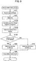
- FIG. 9 is a flowchart of the second determination process.
- the second determination process is configured such that, with respect to the first determination process according to the first exemplary embodiment, the process of step S30 is changed to a process of step S130, the process of step S40 is changed to a process of step S140, and the process of step S50 is changed to a process of step S150.
- step S130 the process of step S140, and the process of step S150.
- rotation determination unit 15 calculates, based on one or more captured images acquired by detector 11, a proportion of a high frequency component in a frequency component of pixel values of pixels included in an area of at least one tire of one or more tires detected by detector 11 (step S130).
- rotation determination unit 15 determines, based on the calculated proportion of the high frequency component, whether the tire is rotating (step S140).
- determination unit 14a checks, in the process of step S140, whether there is a tire that is negatively determined by rotation determination unit 15 (step S150).
- step S150 If in the process of step S150 there is a tire that is negatively determined by rotation determination unit 15 (step S150: Yes), determination unit 14a performs a process of step S60.
- step S150 If in the process of step S150 there is no tire that is negatively determined by rotation determination unit 15 (step S150: No), determination unit 14a performs a process of step S70.
- lift-up determining device 10a determines, from a captured image taken by external image capturing device 20, whether there is a tire that is not rotating to such an extent that the vehicle runs. Then, lift-up determining device 10a determines whether at least one axle of the vehicle is lifted up, based on this determination result.
- lift-up determining device 10a can determine in a non-contact manner whether an axle is lifted up.
- lift-up determining device 10a when lift-up determining device 10a is installed, it is not necessary to bury, in a traveling road or the like, a sensor and other components required to determine whether an axle is lifted up.
- this lift-up determining device 10a it is possible to make a cost required for installation, repair, or removal of the lift-up determining device lower than before.
- lift-up determining device 10b that is configured such that a part of the components of lift-up determining device 10a according to the second exemplary embodiment is modified.
- Lift-up determining device 10a is an example of a configuration in which it is determined from a captured image whether a tire is rotating, based on a high frequency component in a frequency component of pixel values of a plurality of pixels in an area of the tire in the captured image.
- lift-up determining device 10b is an example of a configuration in which a rotation amount of one tire is calculated from two or more captured images and it is determined, from the calculated rotation amount, whether the tire is rotating.
- lift-up determining device 10b will be described mainly on a difference from lift-up determining device 10a according to the second exemplary embodiment.
- FIG. 10 is a block diagram showing a configuration of lift-up determining device 10b according to the third exemplary embodiment.
- lift-up determining device 10b is configured such that, with respect to lift-up determining device 10a according to the second exemplary embodiment, rotation determination unit 15 is changed to rotation determination unit 15b.
- rotation determination unit 15b calculates a rotation amount of the tire from these two or more captured images and determines, based on the calculated rotation amount, whether the tire is rotating.
- rotation determination unit 15b may calculate a rotation amount of the one tire by tracking movement of the one tire in the second captured image by performing a template matching on the second captured image by using pixel values of pixels included in an area of the one tire detected in the first captured image.
- FIG. 11 is a schematic diagram showing that one tire makes a rotation between the first captured image and the second captured image.
- rotation determination unit 15b may calculate the rotation amount of the tire by performing template matching by using, for example, an edge part, of a wheel, having a characteristic brightness, a pixel part corresponding to a rubber plug provided on the wheel of the detected tire, or other parts. Further, detector 11 may calculate the rotation amount of the tire by calculating an optical flow by using these parts.
- rotation determination unit 15b may estimate the rotation amount of the detected tire from, for example, a travel distance of the tire in the traveling direction of vehicle 40 and a radius of the tire, and may limit, based on the estimated rotation amount, an area in which the template matching is performed
- rotation determination unit 15b may determine that the tire is not rotating.
- the above predetermined value may be any value, as long as the value makes it possible to distinguish between a tire rotating to such an extent that the vehicle runs and a tire not rotating to such an extent that the vehicle runs. Further, the above predetermined values may change depending on an imaging condition (such as an imaging cycle when two or more captured images are taken) when captured images are taken by image capturing device 20.
- Lift-up determining device 10b performs, as a characteristic operation of lift-up determining device 10b, a third determination process configured by modifying a part of the second determination process according to the second exemplary embodiment.
- the third determination process will be described mainly on the difference from the second determination process according to the second exemplary embodiment.
- FIG. 12 is a flowchart of the third determination process.
- the third determination process is configured such that, with respect to the second determination process according to the second exemplary embodiment, the process of step S130 is changed to a process of step S230, and the process of step S140 is changed to a process of step S240.
- step S230 a description will be mainly given on the process of step S230, and the process of step S240.
- rotation determination unit 15b calculates a rotation amount of one tire from two or more captured images acquired by detector 11 amount (step S230).
- rotation determination unit 15b determines, based on the calculated rotation amount, whether the tire is rotating (step S240).
- step S240 determines whether the process of step S240 is finished.
- lift-up determining device 10b determines, from captured images taken by external image capturing device 20, whether there is a tire that is not rotating to such an extent that the vehicle runs. Then, lift-up determining device 10b determines whether at least one axle of the vehicle is lifted up, based on this determination result.
- lift-up determining device 10b can determine in a non-contact manner whether an axle is lifted up.
- lift-up determining device 10b when lift-up determining device 10b is installed, it is not necessary to bury, in a traveling road or the like, a sensor and other components required to determine whether an axle is lifted up.
- this lift-up determining device 10b it is possible to make a cost required for installation, repair, or removal of the lift-up determining device lower than before.
- lift-up determining device 10c that is configured such that a part of the components of lift-up determining device 10 according to the first exemplary embodiment is modified.
- Lift-up determining device 10 is an example of a configuration with which it is determined whether an axle of a target vehicle is lifted up, by determining from a captured image whether there is a tire on a middle axle lifted up to such an extent that the tire is not in contact with the ground.
- lift-up determining device 10c is an example of a configuration with which, by determining, from a captured image, whether there is a tire directly under which a local region of a road surface is not deflected, it is determined whether an axle of a target vehicle is lifted up.
- lift-up determining device 10c will be described mainly on a difference from lift-up determining device 10 according to the first exemplary embodiment.
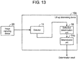
- FIG. 13 is a block diagram showing a configuration of lift-up determining device 10c according to the fourth exemplary embodiment.
- lift-up determining device 10c is configured such that, with respect to lift-up determining device 10 according to the first exemplary embodiment, calculator 12 and position determination unit 13 are removed, determination unit 14 is changed to determination unit 14c, and deflection determination unit 16 is added.
- Deflection determination unit 16 may determine, based on one or more captured images acquired by detector 11, whether a local region or local regions of a road surface located at the lowest point or lowest points of one or more tires detected by detector 11 are deflected by greater than or equal to a predetermined value.
- a phenomenon is known to occur, and in that phenomenon, when a tire is in contact with a road surface, a local region of the road surface with which the tire is in contact is deflected by an axle load applied via the tire, by a deflection amount corresponding to the axle load.
- Deflection determination unit 16 determines whether the deflection amount due to this phenomenon is greater than or equal to a predetermined value.
- deflection determination unit 16 previously stores, for example, a captured image of traveling road 30 that is included in an imaging area of device 20 and is not deflected (for example, a captured image of traveling road 30 taken by image capturing device 20 when no vehicle is running, and hereinafter this captured image is also referred to as a "reference image"). Further, deflection determination unit 16 may calculate the deflection amount of the local region of the road surface located at the lowest point of the tire by comparing the captured image acquired by detector 11 with a previously stored reference image, and may determine whether the calculated deflection amount is greater than or equal to the predetermined value.
- the above predetermined value can be any value as long as the value makes it possible to distinguish between a state where the road receives an axle load because a tire is in contact with the ground and a state where the road surface does not receive an axle load because a tire is not in contact with the ground.
- the above predetermined value may be, for example, a predetermined pixel number of the captured image (for example, 0.1 pixels) or may be, for example, a predetermined distance converted to the real space (for example, 1 mm).
- the above predetermined values may change depending on an imaging condition (such as atmospheric temperature, humidity, road surface temperature, or weather) when a captured image is taken by image capturing device 20.
- the above setting value may change depending on a type of the target tire, a type of a vehicle attached with the target tire, and the like. Further, the above predetermined value may change depending on the position of the lowest point of the target tire.
- Determination unit 14c determines, based on the detection result of detector 11, whether at least one axle of vehicle 40 is lifted up.
- determination unit 14c negatively performs the above determination, which is to be made by determination unit 14c, if there is a tire that is positively determined by deflection determination unit 16.
- a tire on a lifted-up axle is not in contact with a road surface while the vehicle is running. Therefore, if a running vehicle has a tire directly under which the local region of the road surface is not deflected, it means that an axle of the vehicle to which the tire is attached is lifted up.
- determination unit 14c negatively performs the above determination, which is to be made by determination unit 14c, if there is no middle tire that is negatively determined by deflection determination unit 16.
- determination unit 14c outputs the determination result to the outside.
- Lift-up determining device 10c performs, as a characteristic operation of lift-up determining device 10c, a fourth determination process configured by modifying a part of the first determination process according to the first exemplary embodiment.
- the fourth determination process will be described mainly on the difference from the first determination process according to the first exemplary embodiment.
- FIG. 14 is a flowchart of the fourth determination process.
- the fourth determination process is configured such that, with respect to the first determination process according to the first exemplary embodiment, the process of step S30 is changed to a process of step S330, the process of step S40 is changed to a process of step S340, and the process of step S50 is changed to a process of step S350.
- step S330 the process of step S340, and the process of step S350.
- deflection determination unit 16 calculates, based on one or more captured images acquired by detector 11, a deflection amount or deflection amounts of a local region or local regions of a road surface located directly under a lowest point or lowest points of one or more tires detected by detector 11 (step S330).
- deflection determination unit 16 determines whether the calculated deflection amount or deflection amount are greater than or equal to a predetermined value (step S340).
- determination unit 14c checks, in the process of step S340, whether there is a tire that is negatively determined by deflection determination unit 16 (step S350).
- step S350 If in the process of step S350 there is a tire that is negatively determined by deflection determination unit 16 (step S350: Yes), determination unit 14c performs a process of step S60.
- step S350 If in the process of step S350 there is no tire that is negatively determined by deflection determination unit 16 (step S350: No), determination unit 14c performs a process of step S70.
- lift-up determining device 10c determines, from a captured image taken by external image capturing device 20, whether there is a tire located directly under which a local region of a road surface is not deflected by greater than or equal to a predetermined value. Then, lift-up determining device 10c determines whether at least one axle of the vehicle is lifted up, based on this determination result.
- lift-up determining device 10c can determine in a non-contact manner whether an axle is lifted up.
- lift-up determining device 10c when lift-up determining device 10c is installed, it is not necessary to bury, in a traveling road or the like, a sensor and other components required to determine whether an axle is lifted up.
- this lift-up determining device 10c it is possible to make a cost required for installation, repair, or removal of the lift-up determining device lower than before.
- the first to fourth exemplary embodiments have been described as illustrations of the technique disclosed in the present application.
- the technique in the present disclosure is not limited to the first to fourth exemplary embodiments, and are applicable to exemplary embodiments in which changes, replacements, additions, omissions, or the like are made as appropriate.
- Lift-up determining device 10, lift-up determining device 10a, lift-up determining device 10b, and lift-up determining device 10c illustrated in the first to fourth exemplary embodiments are examples each configured to include any one of position determination unit 13 according to first exemplary embodiment, rotation determination unit 15 according to second exemplary embodiment, rotation determination unit 15b according to the third exemplary embodiment, and deflection determination unit 16 according to the fourth exemplary embodiment.
- another example can be considered such that the example is configured to include two or more of position determination unit 13 according to the first exemplary embodiment, rotation determination unit 15 according to the second exemplary embodiment, rotation determination unit 15b according to the third exemplary embodiment, and deflection determination unit 16 according to the fourth exemplary embodiment.
- it may be determined whether at least one axle of vehicle 40 is lifted up, based on determination results by these two or more determination units.
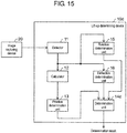
- FIG. 15 is a block diagram showing a configuration of lift-up determining device 10d according to another exemplary embodiment.
- lift-up determining device 10d is configured to include detector 11, calculator 12, and position determination unit 13 according to the first exemplary embodiment, rotation determination unit 15 according to the second exemplary embodiment, and deflection determination unit 16 and determination unit 14d according to the fourth exemplary embodiment.
- Determination unit 14d determines whether at least one axle of vehicle 40 is lifted up, based on a determination result of position determination unit 13, a determination result by rotation determination unit 15, and a determination result by deflection determination unit 16.
- determination unit 14d takes, for example, a majority vote or a weighted majority vote among the determination result of position determination unit 13, the determination result of rotation determination unit 15, and the determination result of deflection determination unit 16. Then, determination unit 14d may determine, following the determination result accounting for the largest number, whether at least one axle of vehicle 40 is lifted up.
- determination unit 14d may apply, for example, an evaluation function using likelihood to the determination result by position determination unit 13, the determination result by rotation determination unit 15, and the determination result by deflection determination unit 16, thereby calculating degrees of probabilities of these determination results. Then, determination unit 14d may determine, following the most probable determination result, whether at least one axle of vehicle 40 is lifted up.
- lift-up determining device 10c determines whether the axle of a target vehicle is lifted up, by determining, from a captured image, whether there is a tire directly under which a local region of a road surface is not deflected.
- lift-up determining device 10c may be configured such that lift-up determining device 10c determines whether the axle of the target vehicle is lifted up, by, for example, determining from a captured image whether there is a tire at the lowest point of which a local region is deflected.
- deflection determination unit 16 determines whether a local region or local regions of a road surface or road surfaces directly under the lowest point or the lowest points of one or more tires detected by detector 11 are deflected by greater than or equal to a predetermined value, based on one or more captured images acquired by detector 11.
- deflection determination unit 16 may be configured, for example, as follows. Instead of directly calculating the deflection amount of the local region at the lowest point of the target tire, deflection determination unit 16 calculated a tire profile of a target tire, and if the calculated tire profile is less than or equal to a predetermined value, deflection determination unit 16 determines that the local region at the lowest point of the tire is deflected by greater than or equal to a predetermined value.
- lift-up determining device 10a lift-up determining device 10a
- lift-up determining device 10b lift-up determining device 10c
- lift-up determining device 10d may be individually integrated into one chips by using a semiconductor device such as an IC (Integrated Circuit) or an LSI (Large Scale Integration), or a part of or the whole of each component may be integrated into one chip.
- a semiconductor device such as an IC (Integrated Circuit) or an LSI (Large Scale Integration)
- LSI Large Scale Integration
- the circuit integration is not necessarily implemented by an LSI, and may be implemented by a dedicated circuit or a general-purpose processor.
- FPGA Field Programmable Gate Array
- reconfigurable processor in which connections or settings of circuit cells in the LSI can be reconfigured.
- all or a part of various processes described above may be implemented by hardware such as an electronic circuit, or may be implemented by using software.
- processing by software is implemented in such a way that a processor included in the lift-up determining device executes a program stored in the memory.
- the program may be recorded on a recording medium to be distributed or circulated.
- the distributed program is installed in another device including a processor, and the program is executed by the processor, so that the device can execute the above processes.
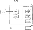
- FIG. 16 shows toll setting system 100 according to the present disclosure.
- Toll setting system 100 includes lift-up determining device 10, image capturing device 20, and server 50.
- Lift-up determining device 10 includes decision unit 19.
- decision unit 19 may be implemented by an electronic circuit in the same way as the other components of lift-up determining device 10 or may be implemented by a processor of lift-up determining device 10 executing a program.
- Server 50 includes a processor and a memory. A function of server 50 may be implemented by, for example, a processor executing a program stored in the memory.
- Decision unit 19 determines a number of axle or axles that are on a vehicle included in a captured image and are not lifted up, based on a determination result by determination unit 14. For example, in a case where three axles are detected in a captured image and only one axle is lifted up, decision unit 19 determines the number of axles that are not lifted up to be two.
- Server 50 sets a toll for the vehicle included in the captured image, based on the result determined by decision unit 19. For example, server 50 may set a toll of a vehicle higher as the number of axles that are not lifted up is larger.
- the above configuration enables a toll for a vehicle to be set by using a captured image by image capturing device 20 without using a sensor buried in a traveling road. As a result, a toll for a vehicle can be set at a lower cost than before.
- the present disclosure can be used for a lift-up determining device that determines whether one or more axles of a vehicle are lifted up.
Landscapes
- Engineering & Computer Science (AREA)
- Theoretical Computer Science (AREA)
- General Physics & Mathematics (AREA)
- Physics & Mathematics (AREA)
- Computer Vision & Pattern Recognition (AREA)
- Multimedia (AREA)
- Health & Medical Sciences (AREA)
- General Health & Medical Sciences (AREA)
- Databases & Information Systems (AREA)
- Software Systems (AREA)
- Medical Informatics (AREA)
- Evolutionary Computation (AREA)
- Computing Systems (AREA)
- Artificial Intelligence (AREA)
- Psychiatry (AREA)
- Social Psychology (AREA)
- Human Computer Interaction (AREA)
- Length Measuring Devices By Optical Means (AREA)
- Traffic Control Systems (AREA)
- Image Analysis (AREA)
- Tires In General (AREA)
Abstract
Description
- The present disclosure relates to a lift-up determining device that determines whether one or more axles of a vehicle are lifted up.
- Conventionally, some of vehicles having three or more axles are equipped with a lift axle mechanism. The lift axle mechanism brings up, in other words, lifts up at least one axle such that tires on the axle are not in contact with the ground.
- Meanwhile, some toll roads have a toll system in which a toll is different depending on the number of axles whose tires are in contact with the ground.
- Such toll roads are desired to be installed with a lift-up determining device that determines whether an axle of a vehicle running on the toll road is lifted up.
- As a known example of conventional lift-up determining devices, an axle number detection device is described in, for example,
PTL 1. - PTL 1: Unexamined Japanese Patent Publication No.
2016-162354 - Regarding the above conventional axle number detection device, it is necessary to bury a road plate in a traveling road to detect when a traveling vehicle steps on the road. Therefore, it needs a certain cost to install, repair, or remove the above conventional axle number detection device.
- The present disclosure is made in view of the above issues, and an object of the present disclosure is to provide a lift-up determining device with which the cost required for installation, repair, or removal of the lift-up determining device can be made lower than before, and to provide a lift-up determining method having such features.
- A lift-up determining device according to an aspect of the present disclosure includes a detector and a determination unit. The detector acquires a captured image including a tire on an axle of a vehicle and detects the tire from the captured image. The determination unit determines whether the axle is lifted up, based on the detection result of the detector.
- A lift-up determining method according to an aspect of the present disclosure acquires a captured image including a tire of an axle of a vehicle, detects the tire from the captured image, and determines whether the axle is lifted up.
- With the above lift-up determining device and lift-up determining method according to the present disclosure, it is possible to make the cost required for installation, repair, or removal of the lift-up determining device lower than before.
-
-
FIG. 1 is a schematic diagram showing an example of when it is determined whether lift-up is being performed. -
FIG. 2 is a block diagram showing a configuration of a lift-up determining device according to a first exemplary embodiment. -
FIG. 3 is a schematic diagram showing an example of a captured image. -
FIG. 4A is a schematic diagram showing an example of a captured image. -
FIG. 4B is a schematic diagram showing an example of a captured image. -
FIG. 5 is a schematic diagram showing a baseline. -
FIG. 6 is a schematic diagram showing a baseline. -
FIG. 7 is a flowchart of a first determination process. -
FIG. 8 is a block diagram showing a configuration of a lift-up determining device according to a second exemplary embodiment. -
FIG. 9 is a flowchart of a second determination process. -
FIG. 10 is a block diagram showing a configuration of a lift-up determining device according to a third exemplary embodiment. -
FIG. 11 is a schematic diagram showing when a tire is rotating. -
FIG. 12 is a flowchart of a third determination process. -
FIG. 13 is a block diagram showing a configuration of a lift-up determining device according to a fourth exemplary embodiment. -
FIG. 14 is a flowchart of a fourth determination process. -
FIG. 15 is a block diagram showing a configuration of a lift-up determining device according to another exemplary embodiment. -
FIG. 16 is a block diagram showing a configuration of a toll setting system according to another exemplary embodiment. - A lift-up determining device according to an aspect of the present disclosure includes a detector and a determination unit. The detector acquires a captured image including a tire on an axle of a vehicle and detects the tire from the captured image. The determination unit determines whether the axle is lifted up, based on the detection result of the detector.
- With this configuration, this lift-up determining device can determine in a non-contact manner whether at least one axle of a vehicle is lifted up.
- Therefore, when this lift-up determining device is installed, it is not necessary to bury, in a traveling road or the like, a sensor and other components required to determine whether an axle is lifted up.
- Therefore, with this lift-up determining device, it is possible to make a cost required for installation, repair, or removal of the lift-up determining device lower than before.
- The above lift-up determining device may further include a position determination unit. If the tire is a middle tire located between a front-most front wheel tire on the vehicle and a rear-most rear wheel tire of the vehicle, the position determination unit may determine whether a lowest point of the middle tire is apart by greater than or equal to a predetermined value on an upper side of the vehicle from a baseline that extends, from a lowest point of the rear wheel tire, in a traveling direction of the vehicle. The determination unit may determine that the axle is lifted up when the position determination unit determines that the lowest point of the middle tire is apart by greater than or equal to the predetermined value on the upper side of the vehicle from the baseline.
- The above lift-up determining device may further include a calculator. The calculator may calculate, from the captured image, a straight line connecting the lowest point of the front wheel tire and the lowest point of the rear wheel tire. The position determination unit may use the straight line calculated by the calculator as the baseline.
- The above lift-up determining device may further include a rotation determination unit. The rotation determination unit may determine whether the tire detected by the detector is rotating, based on the captured image. If the rotation determination unit determines that the tire is not rotating, the determination unit may determine that the axle is lifted up.
- In the above lift-up determining device, the rotation determination unit may determine whether the tire is rotating, based on a frequency component of a plurality of pixels included in an area of the tire.
- In the above lift-up determining device, the rotation determination unit may determine whether the tire detected by the detector is rotating, based on a result of comparison between the frequency component and a frequency component of a plurality of pixels included in an area of the front-most front wheel tire of the vehicle.
- In the above lift-up determining device, the rotation determination unit may determine whether the tire detected by the detector is rotating, based on a result of comparison between the frequency component and a frequency component of a plurality of pixels included in an area of the rear-most rear wheel tire of the vehicle.
- In the above lift-up determining device, the detector may acquire another captured image including a tire and may detect the tire from the another captured image. The rotation determination unit may calculate a rotation amount of the tire based on the captured image and the another captured image and may determine whether the tire is rotating, based on the calculated rotation amount.
- The above lift-up determining device may further include a deflection determination unit. The deflection determination unit may determine, based on the captured image, whether a local region of a road surface located directly under the lowest point of the tire detected by the detector is deflected by greater than or equal to a predetermined value. If the deflection determination unit determines that the local region is not deflected by greater than or equal to the predetermined value, the determination unit may determine that the axle is lifted up.
- The above lift-up determining device may further include a position determination unit, a rotation determination unit, and a deflection determination unit. If the tire is a middle tire located between a front-most front wheel tire on the vehicle and a rear-most rear wheel tire of the vehicle, the position determination unit may determine whether a lowest point of the middle tire is apart by greater than or equal to a predetermined value on an upper side of the vehicle from a baseline that extends, from a lowest point of the rear wheel tire, in a traveling direction of the vehicle. The rotation determination unit may determine whether the tire detected by the detector is rotating, based on the captured image. The deflection determination unit may determine, based on the captured image, whether a local region of a road surface located directly under the lowest point of the tire detected by the detector is deflected by greater than or equal to a predetermined value. The determination unit may determine whether the axle is lifted up, based on the determination result of the position determination unit, the determination result of the rotation determination unit, and the determination result of the deflection determination unit.
- A lift-up determining method according to an aspect of the present disclosure acquires a captured image including a tire on an axle of a vehicle, detects the tire from the captured image, and determines whether the axle is lifted up.
- With this configuration, a lift-up determining device using the lift-up determining method can determine in a non-contact manner whether at least one axle of a vehicle is lifted up.
- Therefore, when the lift-up determining device using this lift-up determining method is installed, it is not necessary to bury, in a traveling road or the like, a sensor and other components required to determine whether an axle is lifted up.
- Therefore, with this lift-up determining method, it is possible to make a cost required for installation, repair, or removal of the lift-up determining device lower than before.
- Note that these generic or specific aspects may be implemented by using a system, a method, an integrated circuit, a computer program, or a computer-readable recording medium such as a compact disc read only memory (CD-ROM), and may also be implemented by any combination of the system, the method, the integrated circuit, the computer program, and the recording medium.
- Hereinafter, specific examples of a lift-up determining device according to an aspect of the present disclosure will be described. Note that each of the exemplary embodiments to be described below illustrates one preferred specific example of the present disclosure. Numerical values, shapes, materials, components, arrangement positions and connection configurations of the components, steps, processing order of the steps, and the like shown in the following exemplary embodiments are just an example, and are not intended to limit the present disclosure. The present disclosure is limited only by the scope of the claims. Therefore, among the components in the following exemplary embodiments, components not described in any of independent claims indicating the most generic concept of the present disclosure are not essential for achieving the object of the present disclosure but are described as components constituting a further preferable configuration.
- In this exemplary embodiment, as an aspect of the present disclosure, there will be described a lift-up determining device that determines whether at least one axle of a vehicle is lifted up.
- This lift-up determining device acquires from the outside a captured image of a vehicle including a tire. Then, the lift-up determining device determines whether at least one axle of the vehicle is lifted up, based on the acquired captured image.
- Hereinafter, this lift-up determining device will be described in detail with reference to the drawings.
-
FIG. 1 is a schematic diagram showing an example when lift-up determiningdevice 10 according to the first exemplary embodiment determines whether at least one axle ofvehicle 40 travelling on travelingroad 30 is lifted up. - In this case, for example, lift-up determining
device 10 is connected to image capturingdevice 20 that captures one or more captured images including one or more tires ofvehicle 40 running on travelingroad 30 To lift-up determiningdevice 10, one or more captured images taken byimage capturing device 20 are output fromimage capturing device 20. -
FIG. 2 is a block diagram showing a configuration of lift-up determiningdevice 10. - As shown in
FIG. 2 , lift-up determiningdevice 10 is configured to includedetector 11,calculator 12,position determination unit 13, anddetermination unit 14. - Lift-up determining
device 10 is implemented, for example, such that, in a computer (not shown) including a microprocessor (not shown) and a memory (not shown), the microprocessor executes a program stored in the memory. -
Detector 11 acquires one or more captured images including a tire on an axle of one vehicle, fromimage capturing device 20. Then,detector 11 detects one or more tires from the acquired one or more captured images. -
Detector 11 may detect a tire by, for example, previously machine learning on identification of tire. Further,detector 11 may detect a tire by, for example, using a template matching method. -
FIGS. 3 ,4A, and 4B are schematic diagrams each showing an example of a captured image acquired bydetector 11. -
Detector 11 may acquire, fromimage capturing device 20, one captured image includingfront wheel tire 21 on a front-most axle ofvehicle 40 andrear wheel tire 22 on a rear-most axle ofvehicle 40, for example, as shown inFIG. 3 . - Further,
detector 11 may acquire, fromimage capturing device 20, a plurality of captured images each of which does not includefront wheel tire 21 andrear wheel tire 22 ofvehicle 40 at the same time, for example, as shown inFIGS. 4A and 4B . -
Calculator 12 calculates a baseline that extends from a lowest point ofrear wheel tire 22 in a traveling direction ofvehicle 40, from the one or more captured images acquired bydetector 11. - For example, in a case where a captured image acquired by
detector 11 is one captured image includingfront wheel tire 21 andrear wheel tire 22 ofvehicle 40 as shown inFIG. 3 ,calculator 12 may calculate, as the above baseline, a straight line connecting a lowest point offront wheel tire 21 and the lowest point ofrear wheel tire 22 by using a detection result ofdetector 11. -
FIG. 5 is a schematicdiagram showing baseline 25a calculated bycalculator 12 in the above example. - Alternatively, for example, in the case where the captured image acquired by
detector 11 is a captured image includingrear wheel tire 22 ofvehicle 40 but not includingfront wheel tire 21 as shown inFIG. 4B ,calculator 12 may calculates, as the above baseline, a straight line that extends from the lowest point ofrear wheel tire 22 in the traveling direction of a driving lane on whichvehicle 40 is running, by using a detection result ofdetector 11. -
FIG. 6 is a schematicdiagram showing baseline 25b calculated bycalculator 12 in the above example. - Alternatively, for example, in a case where the captured images acquired by
detector 11 are a plurality of captured images (two images, in this case) each of which does not includefront wheel tire 21 andrear wheel tire 22 ofvehicle 40 at the same time as shown inFIGS. 4A and 4B ,calculator 12 may compose these plurality of captured images to generate one composite image includingfront wheel tire 21 andrear wheel tire 22. Then,calculator 12 may calculate, as the above baseline, a straight line connecting the lowest point offront wheel tire 21 and the lowest point ofrear wheel tire 22 by using the detection result ofdetector 11 from the composed composite image. -
Position determination unit 13 determines whether the lowest point of a tire that is included in the one or more tires detected bydetector 11 and is other thanfront wheel tire 21 orrear wheel tire 22 of vehicle 40 (in this case, the tire is, for example,tires FIGS. 3 ,4B ,5, and 6 , and hereinafter, referred to as "middle tire") is apart by greater than or equal to a predetermined value on the upper side ofvehicle 40 from the baseline (in this case, the baseline is, for example,baseline 25a inFIG. 5 orbaseline 25b inFIG. 6 ) calculated by the calculator. - Here, the above predetermined value may be any value as long as the value indicates that a tire on a middle axle is lifted up by a lift axle mechanism to such an extent that the tire is not in contact with the ground. The above predetermined value may be, for example, a predetermined pixel number of the captured image (for example, 100 pixels) or may be, for example, a predetermined distance converted to the real space (for example, 10 cm).
-
Determination unit 14 determines, based on the detection result ofdetector 11, whether at least one axle ofvehicle 40 is lifted up. - More specifically,
determination unit 14 positively performs the above determination, which is to be made bydetermination unit 14, if there is a tire that is positively determined byposition determination unit 13. - In general, regarding a vehicle equipped with a lift axle mechanism, a middle tire on a middle axle other than the front-most axle and the rear-most axle of the vehicle is an object to be lifted up. Therefore, in the target vehicle, if the lowest point of the middle tire on the middle axle is apart by greater than or equal to the above predetermined value on the upper side of the vehicle from the baseline that extends from the lowest point of the rear wheel tire on the rear-most axle of the vehicle in the traveling direction of the vehicle, it means that the middle axle of the vehicle is lifted up.
- Further,
determination unit 14 negatively performs the above determination, which is to be made bydetermination unit 14, if there is no middle tire that is positively determined byposition determination unit 13. - Then,
determination unit 14 outputs the determination result to the outside. - An operation performed by lift-up determining
device 10 having the above configuration will be described below with reference to the drawing. - Lift-up determining
device 10 performs a first determination process as a characteristic operation of lift-up determiningdevice 10. - The first determination process is a process that determines, if
image capturing device 20 has output one or more captured images including one or more tires of one vehicle, whether at least one or more axles of the vehicle are lifted up. -
FIG. 7 is a flowchart of the first determination process. - The first determination process is started upon output of one or more captured images including one or more tires of one
vehicle 40 fromimage capturing device 20 to lift-up determiningdevice 10. - When the first determination process is started,
detector 11 acquires fromimage capturing device 20 one or more captured images including one or more tires of one vehicle 40 (step S10). - Then,
detector 11 detects one or more tires from the acquired one or more captured images (step S20). - When
detector 11 has detected one or more tires,calculator 12 calculates a baseline that extends from the lowest point ofrear wheel tire 22 ofvehicle 40 in a traveling direction ofvehicle 40, from the one or more captured images acquired by detector 11 (step S30). - When
calculator 12 has calculated the baseline,position determination unit 13 determines, regarding the middle tire on the middle axle of the one or more tires detected bydetector 11, whether the lowest point of the middle tire is apart by greater than or equal to a predetermined value on the upper side ofvehicle 40 from the baseline calculated by calculator 12 (step S40). - When the determination of
position determination unit 13 is finished,determination unit 14 checks whether there is a tire that was positively determined byposition determination unit 13 in the process of step S40 (step S50). - In the process of step S50, if there is a tire that was positively determined by position determination unit 13 (step S50: Yes),
determination unit 14 determines that at least one axle ofvehicle 40 is lifted up (step S60). - In the process of step S50, if there is no tire that was positively determined by position determination unit 13 (step S50: No),
determination unit 14 determines that no axle ofvehicle 40 is lifted up (step S70). - When the process of step S60 or step S70 is finished,
determination unit 14 outputs a determination result to the outside (step S80). - When the process of step S80 is finished, lift-up determining
device 10 finishes the first determination process. - As described above, lift-up determining
device 10 determines, from a captured image taken by externalimage capturing device 20, whether there is a tire on a middle axle lifted up to such an extent that the tire is not in contact with the ground. Then, lift-up determiningdevice 10 determines whether at least one axle of the vehicle is lifted up, based on this determination result. - In this way, lift-up determining
device 10 can determine in a non-contact manner whether an axle is lifted up. - Therefore, when lift-up determining
device 10 is installed, it is not necessary to bury, in a traveling road or the like, a sensor and other components required to determine whether an axle is lifted up. - Therefore, by using this lift-up determining
device 10, it is possible to make a cost required for installation, repair, or removal of the lift-up determining device lower than before. - In this exemplary embodiment, as an aspect of the present disclosure, there will be described lift-up determining
device 10a that is configured such that a part of the configuration of lift-up determiningdevice 10 according to the first exemplary embodiment is modified. - Lift-up determining
device 10 according to the first exemplary embodiment is an example of a configuration in which, by determining from a captured image whether there is a middle tire on a middle axle lifted up to such an extent that the tire is not in contact with the ground, it is determined whether an axle of a target vehicle is lifted up. - In contrast, lift-up determining
device 10a according to the second exemplary embodiment is an example of a configuration in which, by determining from a captured image whether there is a tire that is not rotating to such an extent that the vehicle runs, it is determined whether an axle of a target vehicle is lifted up. - Hereinafter, lift-up determining
device 10a will be described mainly on a difference from lift-up determiningdevice 10 according to the first exemplary embodiment. -
FIG. 8 is a block diagram showing a configuration of lift-up determiningdevice 10a according to the second exemplary embodiment. - As shown in
FIG. 8 , lift-up determiningdevice 10a is configured such that, with respect to lift-up determiningdevice 10 according to the first exemplary embodiment,calculator 12 andposition determination unit 13 are removed,determination unit 14 is changed todetermination unit 14a, androtation determination unit 15 is added. -
Rotation determination unit 15 determines, based on one or more captured images acquired bydetector 11, whether at least one tire of one or more tires detected bydetector 11 is rotating. - More specifically,
rotation determination unit 15 determines whether the tire is rotating, based on a frequency component of a plurality of pixels included in an area of the above at least one tire. - In general, if a tire is imaged while the tire is rotating, the image is susceptible to motion blur due to rotation compared with when the tire is not rotating. Therefore, there is a known phenomenon that, regarding a frequency component of pixel values of a plurality of pixels included in an area of the tire in a captured image having been taken, a proportion of a high frequency component is lowered.
-
Rotation determination unit 15 uses this phenomenon to determine whether the tire is rotating. - Specifically, for example, in a case where a first tire and a second tire are detected by
detector 11, if a proportion of a high frequency component in a frequency component of pixel values of the pixels included in an area of the first tire is greater, by greater than or equal to a first predetermined value, than a proportion of a high frequency component in a frequency component of pixel values of pixels included in an area of the second tire,rotation determination unit 15 may determine that the second tire is not rotating. - Further, for example, regarding
middle tire vehicle 40, if a proportion of a high frequency component in a frequency component of pixel values of a plurality of pixels in an area of the tire is smaller, by greater than or equal to a second predetermined value, than a high frequency component in a frequency component of pixel values of a plurality of pixels included in an area offront wheel tire 21 orrear wheel tire 22 ofvehicle 40,rotation determination unit 15 may determine that suchmiddle tire - Specifically,
rotation determination unit 15 may determine whethermiddle tire 23 detected bydetector 11 is rotating, based on a result of a comparison of a frequency component of a plurality of pixels included in the area ofmiddle tire 23 ofvehicle 40 and a frequency component of a plurality of pixels included in the area offront wheel tire 21. Alternatively,rotation determination unit 15 may determine whethermiddle tire 23 detected bydetector 11 is rotating, based on a result of a comparison of a frequency component of a plurality of pixels included in the area ofmiddle tire 23 ofvehicle 40 and a frequency component of a plurality of pixels included in the area ofrear wheel tire 22. In this operation,rotation determination unit 15 may determine whethermiddle tire 23 is rotating, based on a result of a comparison of a proportion of a high frequency component of a frequency component ofmiddle tire 23 and a proportion of a high frequency component of a frequency component offront wheel tire 21 orrear wheel tire 22. - Alternatively, for example, regarding
middle tire vehicle 40, if a proportion of a high frequency component in a frequency component of pixel values of a plurality of pixels in an area ofmiddle tire rotation determination unit 15 may determine that the tire is not rotating. - In this case, the first predetermined value, the second predetermined value, and the third predetermined value may be any value, as long as the values each make it possible to distinguish between a tire rotating to such an extent that the vehicle runs and a tire not rotating to such an extent that the vehicle runs. Further, the above predetermined values may change depending on an imaging condition (such as a shutter speed) when a captured image is taken by
image capturing device 20. -
Determination unit 14a determines, based on the detection result ofdetector 11, whether at least one axle ofvehicle 40 is lifted up. - More specifically,
determination unit 14a negatively performs the above determination, which is to be made bydetermination unit 14a, if there is a tire that is positively determined byrotation determination unit 15. - In general, regarding a vehicle equipped with a lift axle mechanism, a tire on a lifted-up axle does not rotate while the vehicle is running. Therefore, if a running vehicle has a non-rotating tire, it means that an axle of the vehicle to which the tire is attached is lifted up.
- Further,
determination unit 14a negatively performs the above determination, which is to be made bydetermination unit 14a, if there is no middle tire that is negatively determined byrotation determination unit 15. - Then,
determination unit 14a outputs the determination result to the outside. - An operation performed by lift-up determining
device 10a having the above configuration will be described below with reference to the drawing. - Lift-up determining
device 10a performs, as a characteristic operation of lift-up determiningdevice 10a, a second determination process configured by modifying a part of the first determination process according to the first exemplary embodiment. - Hereinafter, the second determination process will be described mainly on the difference from the first determination process according to the first exemplary embodiment.
-
FIG. 9 is a flowchart of the second determination process. - As shown in
FIG. 9 , the second determination process is configured such that, with respect to the first determination process according to the first exemplary embodiment, the process of step S30 is changed to a process of step S130, the process of step S40 is changed to a process of step S140, and the process of step S50 is changed to a process of step S150. - Therefore, in the following, a description will be mainly given on the process of step S130, the process of step S140, and the process of step S150.
- In the second determination process, when a process of step S20 is finished,
rotation determination unit 15 calculates, based on one or more captured images acquired bydetector 11, a proportion of a high frequency component in a frequency component of pixel values of pixels included in an area of at least one tire of one or more tires detected by detector 11 (step S130). - Then,
rotation determination unit 15 determines, based on the calculated proportion of the high frequency component, whether the tire is rotating (step S140). - When the determination by
rotation determination unit 15 is finished,determination unit 14a checks, in the process of step S140, whether there is a tire that is negatively determined by rotation determination unit 15 (step S150). - If in the process of step S150 there is a tire that is negatively determined by rotation determination unit 15 (step S150: Yes),
determination unit 14a performs a process of step S60. - If in the process of step S150 there is no tire that is negatively determined by rotation determination unit 15 (step S150: No),
determination unit 14a performs a process of step S70. - As described above, lift-up determining
device 10a determines, from a captured image taken by externalimage capturing device 20, whether there is a tire that is not rotating to such an extent that the vehicle runs. Then, lift-up determiningdevice 10a determines whether at least one axle of the vehicle is lifted up, based on this determination result. - In this way, lift-up determining
device 10a can determine in a non-contact manner whether an axle is lifted up. - Therefore, when lift-up determining
device 10a is installed, it is not necessary to bury, in a traveling road or the like, a sensor and other components required to determine whether an axle is lifted up. - Therefore, by using this lift-up determining
device 10a, it is possible to make a cost required for installation, repair, or removal of the lift-up determining device lower than before. - In this exemplary embodiment, as an aspect of the present disclosure, there will be described lift-up determining
device 10b that is configured such that a part of the components of lift-up determiningdevice 10a according to the second exemplary embodiment is modified. - Lift-up determining
device 10a according to the second exemplary embodiment is an example of a configuration in which it is determined from a captured image whether a tire is rotating, based on a high frequency component in a frequency component of pixel values of a plurality of pixels in an area of the tire in the captured image. - In contrast, lift-up determining
device 10b according to the third exemplary embodiment is an example of a configuration in which a rotation amount of one tire is calculated from two or more captured images and it is determined, from the calculated rotation amount, whether the tire is rotating. - Hereinafter, lift-up determining
device 10b will be described mainly on a difference from lift-up determiningdevice 10a according to the second exemplary embodiment. -
FIG. 10 is a block diagram showing a configuration of lift-up determiningdevice 10b according to the third exemplary embodiment. - As shown in
FIG. 10 , lift-up determiningdevice 10b is configured such that, with respect to lift-up determiningdevice 10a according to the second exemplary embodiment,rotation determination unit 15 is changed torotation determination unit 15b. - When
detector 11 has detected one tire from two or more captured images,rotation determination unit 15b calculates a rotation amount of the tire from these two or more captured images and determines, based on the calculated rotation amount, whether the tire is rotating. - More specifically, for example, when one tire is detected from a first captured image and a second captured image (an example of another captured image),
rotation determination unit 15b may calculate a rotation amount of the one tire by tracking movement of the one tire in the second captured image by performing a template matching on the second captured image by using pixel values of pixels included in an area of the one tire detected in the first captured image. -
FIG. 11 is a schematic diagram showing that one tire makes a rotation between the first captured image and the second captured image. - In a case where the tire detected by
detector 11 has a shape, for example, shown inFIG. 11 ,rotation determination unit 15b may calculate the rotation amount of the tire by performing template matching by using, for example, an edge part, of a wheel, having a characteristic brightness, a pixel part corresponding to a rubber plug provided on the wheel of the detected tire, or other parts. Further,detector 11 may calculate the rotation amount of the tire by calculating an optical flow by using these parts. - Further,
rotation determination unit 15b may estimate the rotation amount of the detected tire from, for example, a travel distance of the tire in the traveling direction ofvehicle 40 and a radius of the tire, and may limit, based on the estimated rotation amount, an area in which the template matching is performed - Further, for example, if the rotation amount calculated with respect to the one tire is less than or equal to a predetermined value,
rotation determination unit 15b may determine that the tire is not rotating. - In this case, the above predetermined value may be any value, as long as the value makes it possible to distinguish between a tire rotating to such an extent that the vehicle runs and a tire not rotating to such an extent that the vehicle runs. Further, the above predetermined values may change depending on an imaging condition (such as an imaging cycle when two or more captured images are taken) when captured images are taken by
image capturing device 20. - Lift-up determining
device 10b performs, as a characteristic operation of lift-up determiningdevice 10b, a third determination process configured by modifying a part of the second determination process according to the second exemplary embodiment. - Hereinafter, the third determination process will be described mainly on the difference from the second determination process according to the second exemplary embodiment.
-
FIG. 12 is a flowchart of the third determination process. - As shown in
FIG. 12 , the third determination process is configured such that, with respect to the second determination process according to the second exemplary embodiment, the process of step S130 is changed to a process of step S230, and the process of step S140 is changed to a process of step S240. - Therefore, in the following, a description will be mainly given on the process of step S230, and the process of step S240.
- In the third determination process, when the process of step S20 is finished,
rotation determination unit 15b calculates a rotation amount of one tire from two or more captured images acquired bydetector 11 amount (step S230). - Then,
rotation determination unit 15b determines, based on the calculated rotation amount, whether the tire is rotating (step S240). - When the process of step S240 is finished,
determination unit 14a performs the process of step S150. - As described above, lift-up determining
device 10b determines, from captured images taken by externalimage capturing device 20, whether there is a tire that is not rotating to such an extent that the vehicle runs. Then, lift-up determiningdevice 10b determines whether at least one axle of the vehicle is lifted up, based on this determination result. - In this way, lift-up determining
device 10b can determine in a non-contact manner whether an axle is lifted up. - Therefore, when lift-up determining
device 10b is installed, it is not necessary to bury, in a traveling road or the like, a sensor and other components required to determine whether an axle is lifted up. - Therefore, by using this lift-up determining
device 10b, it is possible to make a cost required for installation, repair, or removal of the lift-up determining device lower than before. - In this exemplary embodiment, as an aspect of the present disclosure, there will be described lift-up determining
device 10c that is configured such that a part of the components of lift-up determiningdevice 10 according to the first exemplary embodiment is modified. - Lift-up determining
device 10 according to the first exemplary embodiment is an example of a configuration with which it is determined whether an axle of a target vehicle is lifted up, by determining from a captured image whether there is a tire on a middle axle lifted up to such an extent that the tire is not in contact with the ground. - In contrast, lift-up determining
device 10c according to the fourth exemplary embodiment is an example of a configuration with which, by determining, from a captured image, whether there is a tire directly under which a local region of a road surface is not deflected, it is determined whether an axle of a target vehicle is lifted up. - Hereinafter, lift-up determining
device 10c will be described mainly on a difference from lift-up determiningdevice 10 according to the first exemplary embodiment. -
FIG. 13 is a block diagram showing a configuration of lift-up determiningdevice 10c according to the fourth exemplary embodiment. - As shown in
FIG. 13 , lift-up determiningdevice 10c is configured such that, with respect to lift-up determiningdevice 10 according to the first exemplary embodiment,calculator 12 andposition determination unit 13 are removed,determination unit 14 is changed todetermination unit 14c, anddeflection determination unit 16 is added. -
Deflection determination unit 16 may determine, based on one or more captured images acquired bydetector 11, whether a local region or local regions of a road surface located at the lowest point or lowest points of one or more tires detected bydetector 11 are deflected by greater than or equal to a predetermined value. - In general, a phenomenon is known to occur, and in that phenomenon, when a tire is in contact with a road surface, a local region of the road surface with which the tire is in contact is deflected by an axle load applied via the tire, by a deflection amount corresponding to the axle load.
-
Deflection determination unit 16 determines whether the deflection amount due to this phenomenon is greater than or equal to a predetermined value. - More specifically,
deflection determination unit 16 previously stores, for example, a captured image of travelingroad 30 that is included in an imaging area ofdevice 20 and is not deflected (for example, a captured image of travelingroad 30 taken byimage capturing device 20 when no vehicle is running, and hereinafter this captured image is also referred to as a "reference image"). Further,deflection determination unit 16 may calculate the deflection amount of the local region of the road surface located at the lowest point of the tire by comparing the captured image acquired bydetector 11 with a previously stored reference image, and may determine whether the calculated deflection amount is greater than or equal to the predetermined value. - In this exemplary embodiment, the above predetermined value can be any value as long as the value makes it possible to distinguish between a state where the road receives an axle load because a tire is in contact with the ground and a state where the road surface does not receive an axle load because a tire is not in contact with the ground. The above predetermined value may be, for example, a predetermined pixel number of the captured image (for example, 0.1 pixels) or may be, for example, a predetermined distance converted to the real space (for example, 1 mm). Further, the above predetermined values may change depending on an imaging condition (such as atmospheric temperature, humidity, road surface temperature, or weather) when a captured image is taken by
image capturing device 20. Further, the above setting value may change depending on a type of the target tire, a type of a vehicle attached with the target tire, and the like. Further, the above predetermined value may change depending on the position of the lowest point of the target tire. -
Determination unit 14c determines, based on the detection result ofdetector 11, whether at least one axle ofvehicle 40 is lifted up. - More specifically,
determination unit 14c negatively performs the above determination, which is to be made bydetermination unit 14c, if there is a tire that is positively determined bydeflection determination unit 16. - In general, regarding a vehicle equipped with a lift axle mechanism, a tire on a lifted-up axle is not in contact with a road surface while the vehicle is running. Therefore, if a running vehicle has a tire directly under which the local region of the road surface is not deflected, it means that an axle of the vehicle to which the tire is attached is lifted up.
- Further,
determination unit 14c negatively performs the above determination, which is to be made bydetermination unit 14c, if there is no middle tire that is negatively determined bydeflection determination unit 16. - Then,
determination unit 14c outputs the determination result to the outside. - An operation performed by lift-up determining
device 10c having the above configuration will be described below with reference to the drawing. - Lift-up determining
device 10c performs, as a characteristic operation of lift-up determiningdevice 10c, a fourth determination process configured by modifying a part of the first determination process according to the first exemplary embodiment. - Hereinafter, the fourth determination process will be described mainly on the difference from the first determination process according to the first exemplary embodiment.
-
FIG. 14 is a flowchart of the fourth determination process. - As shown in
FIG. 14 , the fourth determination process is configured such that, with respect to the first determination process according to the first exemplary embodiment, the process of step S30 is changed to a process of step S330, the process of step S40 is changed to a process of step S340, and the process of step S50 is changed to a process of step S350. - Therefore, in the following, a description will be mainly given on the process of step S330, the process of step S340, and the process of step S350.
- In the fourth determination process, when a process of step S20 is finished,
deflection determination unit 16 calculates, based on one or more captured images acquired bydetector 11, a deflection amount or deflection amounts of a local region or local regions of a road surface located directly under a lowest point or lowest points of one or more tires detected by detector 11 (step S330). - Then,
deflection determination unit 16 determines whether the calculated deflection amount or deflection amount are greater than or equal to a predetermined value (step S340). - When the determination by
deflection determination unit 16 is finished,determination unit 14c checks, in the process of step S340, whether there is a tire that is negatively determined by deflection determination unit 16 (step S350). - If in the process of step S350 there is a tire that is negatively determined by deflection determination unit 16 (step S350: Yes),
determination unit 14c performs a process of step S60. - If in the process of step S350 there is no tire that is negatively determined by deflection determination unit 16 (step S350: No),
determination unit 14c performs a process of step S70. - As described above, lift-up determining
device 10c determines, from a captured image taken by externalimage capturing device 20, whether there is a tire located directly under which a local region of a road surface is not deflected by greater than or equal to a predetermined value. Then, lift-up determiningdevice 10c determines whether at least one axle of the vehicle is lifted up, based on this determination result. - In this way, lift-up determining
device 10c can determine in a non-contact manner whether an axle is lifted up. - Therefore, when lift-up determining
device 10c is installed, it is not necessary to bury, in a traveling road or the like, a sensor and other components required to determine whether an axle is lifted up. - Therefore, by using this lift-up determining
device 10c, it is possible to make a cost required for installation, repair, or removal of the lift-up determining device lower than before. - As described above, the first to fourth exemplary embodiments have been described as illustrations of the technique disclosed in the present application. However, the technique in the present disclosure is not limited to the first to fourth exemplary embodiments, and are applicable to exemplary embodiments in which changes, replacements, additions, omissions, or the like are made as appropriate.
- (1) Lift-up determining
device 10, lift-up determiningdevice 10a, lift-up determiningdevice 10b, and lift-up determiningdevice 10c illustrated in the first to fourth exemplary embodiments are examples each configured to include any one ofposition determination unit 13 according to first exemplary embodiment,rotation determination unit 15 according to second exemplary embodiment,rotation determination unit 15b according to the third exemplary embodiment, anddeflection determination unit 16 according to the fourth exemplary embodiment. - In contrast, another example can be considered such that the example is configured to include two or more of
position determination unit 13 according to the first exemplary embodiment,rotation determination unit 15 according to the second exemplary embodiment,rotation determination unit 15b according to the third exemplary embodiment, anddeflection determination unit 16 according to the fourth exemplary embodiment. In this example, it may be determined whether at least one axle ofvehicle 40 is lifted up, based on determination results by these two or more determination units. -
FIG. 15 is a block diagram showing a configuration of lift-up determiningdevice 10d according to another exemplary embodiment. - As shown in
FIG. 15 , lift-up determiningdevice 10d is configured to includedetector 11,calculator 12, andposition determination unit 13 according to the first exemplary embodiment,rotation determination unit 15 according to the second exemplary embodiment, anddeflection determination unit 16 anddetermination unit 14d according to the fourth exemplary embodiment. -
Determination unit 14d determines whether at least one axle ofvehicle 40 is lifted up, based on a determination result ofposition determination unit 13, a determination result byrotation determination unit 15, and a determination result bydeflection determination unit 16. - More specifically,
determination unit 14d takes, for example, a majority vote or a weighted majority vote among the determination result ofposition determination unit 13, the determination result ofrotation determination unit 15, and the determination result ofdeflection determination unit 16. Then,determination unit 14d may determine, following the determination result accounting for the largest number, whether at least one axle ofvehicle 40 is lifted up. - Alternatively,
determination unit 14d may apply, for example, an evaluation function using likelihood to the determination result byposition determination unit 13, the determination result byrotation determination unit 15, and the determination result bydeflection determination unit 16, thereby calculating degrees of probabilities of these determination results. Then,determination unit 14d may determine, following the most probable determination result, whether at least one axle ofvehicle 40 is lifted up. - (2) In the fourth exemplary embodiment, it is described that lift-up determining
device 10c determines whether the axle of a target vehicle is lifted up, by determining, from a captured image, whether there is a tire directly under which a local region of a road surface is not deflected. - In contrast, lift-up determining
device 10c may be configured such that lift-up determiningdevice 10c determines whether the axle of the target vehicle is lifted up, by, for example, determining from a captured image whether there is a tire at the lowest point of which a local region is deflected. - This configuration example is implemented such that, for example,
deflection determination unit 16 determines whether a local region or local regions of a road surface or road surfaces directly under the lowest point or the lowest points of one or more tires detected bydetector 11 are deflected by greater than or equal to a predetermined value, based on one or more captured images acquired bydetector 11. - In this configuration example,
deflection determination unit 16 may be configured, for example, as follows. Instead of directly calculating the deflection amount of the local region at the lowest point of the target tire,deflection determination unit 16 calculated a tire profile of a target tire, and if the calculated tire profile is less than or equal to a predetermined value,deflection determination unit 16 determines that the local region at the lowest point of the tire is deflected by greater than or equal to a predetermined value. - (3) The components (function blocks) in lift-up determining
device 10, lift-up determiningdevice 10a, lift-up determiningdevice 10b, lift-up determiningdevice 10c, and lift-up determiningdevice 10d may be individually integrated into one chips by using a semiconductor device such as an IC (Integrated Circuit) or an LSI (Large Scale Integration), or a part of or the whole of each component may be integrated into one chip. Further, the circuit integration is not necessarily implemented by an LSI, and may be implemented by a dedicated circuit or a general-purpose processor. It is also possible to use an FPGA (Field Programmable Gate Array), which can be programed after being fabricated as an LSI, or to use a reconfigurable processor, in which connections or settings of circuit cells in the LSI can be reconfigured. Further, when there emerges a technique for circuit integration that replaces the LSI as a result of development of semiconductor technology or another technology derived from semiconductor technology, the function blocks may be integrated by using such techniques. There can be a possibility that biotechnology can be applied. - Further, all or a part of various processes described above may be implemented by hardware such as an electronic circuit, or may be implemented by using software. Note that processing by software is implemented in such a way that a processor included in the lift-up determining device executes a program stored in the memory. Further, the program may be recorded on a recording medium to be distributed or circulated. For example, the distributed program is installed in another device including a processor, and the program is executed by the processor, so that the device can execute the above processes.
- (4)
FIG. 16 shows toll settingsystem 100 according to the present disclosure.Toll setting system 100 includes lift-up determiningdevice 10,image capturing device 20, andserver 50. Lift-up determiningdevice 10 includesdecision unit 19. Note thatdecision unit 19 may be implemented by an electronic circuit in the same way as the other components of lift-up determiningdevice 10 or may be implemented by a processor of lift-up determiningdevice 10 executing a program.Server 50 includes a processor and a memory. A function ofserver 50 may be implemented by, for example, a processor executing a program stored in the memory. -
Decision unit 19 determines a number of axle or axles that are on a vehicle included in a captured image and are not lifted up, based on a determination result bydetermination unit 14. For example, in a case where three axles are detected in a captured image and only one axle is lifted up,decision unit 19 determines the number of axles that are not lifted up to be two. -
Server 50 sets a toll for the vehicle included in the captured image, based on the result determined bydecision unit 19. For example,server 50 may set a toll of a vehicle higher as the number of axles that are not lifted up is larger. - The above configuration enables a toll for a vehicle to be set by using a captured image by
image capturing device 20 without using a sensor buried in a traveling road. As a result, a toll for a vehicle can be set at a lower cost than before. - In addition, an embodiment realized by arbitrary combination of the components and the functions of the above-described exemplary embodiments is included in the scope of the present disclosure.
- The present disclosure can be used for a lift-up determining device that determines whether one or more axles of a vehicle are lifted up.
-
- 10, 10a, 10b, 10c, 10d:
- lift-up determining device
- 11:
- detector
- 12:
- calculator
- 13:
- position determination unit
- 14, 14a, 14b, 14c, 14d:
- determniation unit
- 16:
- deflection determination unit
- 19:
- decision unit
- 20:
- image capturing device
- 50:
- server
- 100:
- toll setting system
Claims (12)
- A lift-up determining device comprising:a detector that acquires a captured image including a tire of an axle of a vehicle and detects the tire from the captured image; anda determination unit that determines whether the axle is lifted up, based on a detection result of the detector.
- The lift-up determining device according to claim 1, further comprising a position determination unit that determines, when the tire is a middle tire located between a front-most front wheel tire of the vehicle and a rear-most rear wheel tire of the vehicle, whether a lowest point of the middle tire is higher than a baseline by a distance greater than or equal to a predetermined value, the baseline extending in a traveling direction of the vehicle from a lowest point of the rear-most rear wheel tire,
wherein when the position determination unit determines that the lowest point of the middle tire is higher than the baseline by the distance greater than or equal to the predetermined value, the determination unit determines that the axle is lifted up. - The lift-up determining device according to claim 2, further comprising a calculator that calculates, from the captured image, a straight line connecting a lowest point of the front-most front wheel tire and the lowest point of the rear-most rear wheel tire,
wherein the position determination unit uses, as the baseline, the straight line calculated by the calculator. - The lift-up determining device according to claim 1, further comprising a rotation determination unit that determines, based on the captured image, whether the tire detected by the detector is rotating,
wherein when the rotation determination unit determines that the tire is not rotating, the determination unit determines that the axle is lifted up. - The lift-up determining device according to claim 4, wherein the rotation determination unit determines whether the tire is rotating, based on a frequency component of a plurality of pixels included in an area of the tire in the captured image.
- The lift-up determining device according to claim 5, wherein the rotation determination unit determines whether the tire detected by the detector is rotating, based on a result of comparison between the frequency component and a frequency component of a plurality of pixels included in an area of a front-most front wheel tire of the vehicle in the captured image.
- The lift-up determining device according to claim 5, wherein the rotation determination unit determines whether the tire detected by the detector is rotating, based on a result of comparison between the frequency component and a frequency component of a plurality of pixels included in an area of a rear-most rear wheel tire of the vehicle in the captured image.
- The lift-up determining device according to claim 4, wherein
the detector acquires another captured image including the tire and detects the tire from the another captured image, and
the rotation determination unit calculates a rotation amount of the tire from the captured image and the another captured image, and determines whether the tire is rotating, based on the calculated rotation amount. - The lift-up determining device according to claim 1, further comprising a deflection determination unit that determines, based on the captured image, whether a local region of a road surface located directly under a lowest point of the tire detected by the detector is deflected by a distance greater than or equal to a predetermined value,
wherein when the deflection determination unit determines that the local region is not deflected by the distance greater than or equal to the predetermined value, the determination unit determines that the axle is lifted up. - The lift-up determining device according to claim 1, further comprising:a position determination unit that determines, when the tire is a middle tire located between a front-most front wheel tire of the vehicle and a rear-most rear wheel tire of the vehicle, whether a lowest point of the middle tire is higher than a baseline by a distance greater than or equal to a predetermined value, the baseline extending in a traveling direction of the vehicle from a lowest point of the rear-most rear wheel tire;a rotation determination unit that determines, based on the captured image, whether the tire detected by the detector is rotating; anda deflection determination unit that determines, based on the captured image, whether a local region of a road surface located directly under the lowest point of the middle tire detected by the detector is deflected by a distance greater than or equal to a predetermined value,wherein the determination unit determines whether the axle is lifted up, based on a determination result of the position determination unit, a determination result of the rotation determination unit, and a determination result of the deflection determination unit.
- The lift-up determining device according to any one of claims 1 to 10, further comprising a decision unit that decides, based on a determination result of the determination unit, a number of axles of the vehicle that are not lifted up.
- A lift-up determining method comprising:acquiring a captured image including a tire of an axle of a vehicle;detecting the tire from the captured image; anddetermining, based on a result of the detecting of the tire, whether the axle is lifted up.
Applications Claiming Priority (2)
| Application Number | Priority Date | Filing Date | Title |
|---|---|---|---|
| JP2017185396 | 2017-09-26 | ||
| PCT/JP2018/019220 WO2019064682A1 (en) | 2017-09-26 | 2018-05-18 | Lift-up determining device and lift-up determining method |
Publications (3)
| Publication Number | Publication Date |
|---|---|
| EP3690847A1 true EP3690847A1 (en) | 2020-08-05 |
| EP3690847A4 EP3690847A4 (en) | 2020-11-04 |
| EP3690847B1 EP3690847B1 (en) | 2025-10-15 |
Family
ID=65900937
Family Applications (1)
| Application Number | Title | Priority Date | Filing Date |
|---|---|---|---|
| EP18861591.8A Active EP3690847B1 (en) | 2017-09-26 | 2018-05-18 | Lift-up determining device and lift-up determining method |
Country Status (5)
| Country | Link |
|---|---|
| US (1) | US11238608B2 (en) |
| EP (1) | EP3690847B1 (en) |
| JP (2) | JP7190680B2 (en) |
| CN (1) | CN111133488B (en) |
| WO (1) | WO2019064682A1 (en) |
Families Citing this family (8)
| Publication number | Priority date | Publication date | Assignee | Title |
|---|---|---|---|---|
| JP7234538B2 (en) * | 2018-08-31 | 2023-03-08 | コニカミノルタ株式会社 | Image processing device, axle number detection system, fee setting device, fee setting system and program |
| EP4024363B1 (en) * | 2019-08-29 | 2024-04-17 | Panasonic Intellectual Property Management Co., Ltd. | Axle number measurement device, axle number measurement system, and axle number measurement method |
| JP7362499B2 (en) * | 2020-02-03 | 2023-10-17 | 三菱重工機械システム株式会社 | Axle number detection device, toll collection system, axle number detection method, and program |
| JP7365254B2 (en) * | 2020-02-03 | 2023-10-19 | 三菱重工機械システム株式会社 | Axle number detection device, toll collection system, axle number detection method, and program |
| JP7296898B2 (en) * | 2020-02-05 | 2023-06-23 | 三菱重工機械システム株式会社 | AXLE NUMBER DETECTION DEVICE, TOLL COLLECTION SYSTEM, AXLE NUMBER DETECTION METHOD, AND PROGRAM |
| JP7759574B2 (en) * | 2021-03-12 | 2025-10-24 | パナソニックIpマネジメント株式会社 | Measurement equipment and programs |
| WO2022269946A1 (en) * | 2021-06-23 | 2022-12-29 | 日本電気株式会社 | Processing device, processing method, and program |
| KR102761764B1 (en) * | 2024-04-17 | 2025-02-05 | 경북대학교 산학협력단 | Apparatus for detecting potential cut-in vehicles and method thereof |
Family Cites Families (16)
| Publication number | Priority date | Publication date | Assignee | Title |
|---|---|---|---|---|
| JPH05225490A (en) * | 1992-02-07 | 1993-09-03 | Toshiba Corp | Vehicle type identification device |
| JPH1166312A (en) * | 1997-08-27 | 1999-03-09 | Nissan Motor Co Ltd | Vehicle recognition device |
| JPH1186185A (en) * | 1997-09-03 | 1999-03-30 | Mitsubishi Heavy Ind Ltd | Vehicle-type discriminating device |
| JP3791380B2 (en) | 2001-10-02 | 2006-06-28 | 日産自動車株式会社 | Ambient vehicle detection device |
| DE102008042024A1 (en) * | 2008-09-12 | 2010-03-18 | Robert Bosch Gmbh | Method and device for optical wheel alignment of motor vehicles |
| EP2721593B1 (en) * | 2011-06-17 | 2017-04-05 | Leddartech Inc. | System and method for traffic side detection and characterization |
| JP5677281B2 (en) * | 2011-12-27 | 2015-02-25 | 株式会社東芝 | Vehicle detection device |
| JP2014128982A (en) * | 2012-12-27 | 2014-07-10 | Tokai Rika Co Ltd | Tire position determination system |
| JP2014215719A (en) * | 2013-04-23 | 2014-11-17 | 株式会社東芝 | Vehicle type determination device |
| DE102014012285A1 (en) * | 2014-08-22 | 2016-02-25 | Jenoptik Robot Gmbh | Method and axle counting device for non-contact axle counting of a vehicle and axle counting system for road traffic |
| JP6403005B2 (en) * | 2014-12-12 | 2018-10-10 | コニカミノルタ株式会社 | Relay connection system, relay connection program |
| JP6569138B2 (en) | 2015-03-04 | 2019-09-04 | 三菱重工機械システム株式会社 | Axle number detection device, vehicle type discrimination system, axle number detection method and program |
| JP6750967B2 (en) | 2016-06-09 | 2020-09-02 | 株式会社東芝 | Vehicle type identification device and vehicle type identification method |
| US10609292B2 (en) * | 2017-02-28 | 2020-03-31 | Panasonic Intellectual Property Management Co., Ltd. | Imaging apparatus, axle load measuring system, and imaging method |
| CN111213192B (en) * | 2017-10-31 | 2022-05-10 | 松下知识产权经营株式会社 | Dual tire determination device and dual tire determination method |
| JP7234538B2 (en) * | 2018-08-31 | 2023-03-08 | コニカミノルタ株式会社 | Image processing device, axle number detection system, fee setting device, fee setting system and program |
-
2018
- 2018-05-18 CN CN201880061954.XA patent/CN111133488B/en active Active
- 2018-05-18 WO PCT/JP2018/019220 patent/WO2019064682A1/en not_active Ceased
- 2018-05-18 EP EP18861591.8A patent/EP3690847B1/en active Active
- 2018-05-18 JP JP2019544239A patent/JP7190680B2/en active Active
-
2020
- 2020-03-06 US US16/810,909 patent/US11238608B2/en active Active
-
2022
- 2022-11-25 JP JP2022188232A patent/JP7511166B2/en active Active
Also Published As
| Publication number | Publication date |
|---|---|
| JPWO2019064682A1 (en) | 2020-09-10 |
| CN111133488A (en) | 2020-05-08 |
| JP7511166B2 (en) | 2024-07-05 |
| WO2019064682A1 (en) | 2019-04-04 |
| JP7190680B2 (en) | 2022-12-16 |
| US11238608B2 (en) | 2022-02-01 |
| JP2023016890A (en) | 2023-02-02 |
| CN111133488B (en) | 2022-05-13 |
| US20200202555A1 (en) | 2020-06-25 |
| EP3690847A4 (en) | 2020-11-04 |
| EP3690847B1 (en) | 2025-10-15 |
Similar Documents
| Publication | Publication Date | Title |
|---|---|---|
| US11238608B2 (en) | Lift-up determining device and lift-up determining method | |
| US9047518B2 (en) | Method for the detection and tracking of lane markings | |
| EP3855215B1 (en) | Depth acquisition device, depth-acquiring method and program | |
| US10339396B2 (en) | Vehicle accessibility determination device | |
| JP6817104B2 (en) | Adhesion detection device, deposit detection method | |
| JP2015153295A (en) | Environment recognition system, vehicle, and camera dirt detection method | |
| WO2014002692A1 (en) | Stereo camera | |
| US11530993B2 (en) | Deposit detection device and deposit detection method | |
| EP3352134A1 (en) | Image processing device, object recognition device, device control system, image processing method, and program | |
| EP3115933A1 (en) | Image processing device, image capturing device, mobile body control system, image processing method, and computer-readable recording medium | |
| EP3584763A1 (en) | Vehicle-mounted environment recognition device | |
| US10521915B2 (en) | Distance measurement device and distance measurement method | |
| WO2006101004A1 (en) | Vehicle-use image processing system, vehicle-use image processing method, vehicle-use image processing program, vehicle, and method of formulating vehicle-use image processing system | |
| US10984273B2 (en) | Attachable matter detection apparatus | |
| JP5983729B2 (en) | White line detection device, white line detection filter device, and white line detection method | |
| JP7283081B2 (en) | Attached matter detection device and attached matter detection method | |
| US20200211194A1 (en) | Attached object detection apparatus | |
| CN113168701A (en) | Method for camera misalignment detection, camera system, computer program product and computer readable medium | |
| EP3115965A2 (en) | Detection device, disparity value deriving device, object recognizing device, device control system, detection method, and program | |
| CN116912167A (en) | Transmission line inspection method, system and controller | |
| KR20150111611A (en) | Apparatus and method for detecting vehicle candidate | |
| US20240001933A1 (en) | Occupant temperature estimating device, occupant state detection device, occupant temperature estimating method, and occupant temperature estimating system | |
| KR101156145B1 (en) | Method and apparatus for processing image of the vehicles, and control apparatus for a vehicle using the method | |
| JP6334773B2 (en) | Stereo camera | |
| JP2026074056A (en) | Line detection device, line detection method, program, and storage medium |
Legal Events
| Date | Code | Title | Description |
|---|---|---|---|
| STAA | Information on the status of an ep patent application or granted ep patent |
Free format text: STATUS: THE INTERNATIONAL PUBLICATION HAS BEEN MADE |
|
| PUAI | Public reference made under article 153(3) epc to a published international application that has entered the european phase |
Free format text: ORIGINAL CODE: 0009012 |
|
| STAA | Information on the status of an ep patent application or granted ep patent |
Free format text: STATUS: REQUEST FOR EXAMINATION WAS MADE |
|
| 17P | Request for examination filed |
Effective date: 20200325 |
|
| AK | Designated contracting states |
Kind code of ref document: A1 Designated state(s): AL AT BE BG CH CY CZ DE DK EE ES FI FR GB GR HR HU IE IS IT LI LT LU LV MC MK MT NL NO PL PT RO RS SE SI SK SM TR |
|
| AX | Request for extension of the european patent |
Extension state: BA ME |
|
| A4 | Supplementary search report drawn up and despatched |
Effective date: 20201006 |
|
| RIC1 | Information provided on ipc code assigned before grant |
Ipc: G06K 9/00 20060101AFI20200930BHEP Ipc: G08G 1/04 20060101ALI20200930BHEP Ipc: G06T 7/73 20170101ALI20200930BHEP Ipc: G08G 1/015 20060101ALI20200930BHEP |
|
| DAV | Request for validation of the european patent (deleted) | ||
| DAX | Request for extension of the european patent (deleted) | ||
| STAA | Information on the status of an ep patent application or granted ep patent |
Free format text: STATUS: EXAMINATION IS IN PROGRESS |
|
| 17Q | First examination report despatched |
Effective date: 20220429 |
|
| REG | Reference to a national code |
Ref legal event code: R079 Ref country code: DE Ref legal event code: R079 Ref document number: 602018086435 Country of ref document: DE Free format text: PREVIOUS MAIN CLASS: G08G0001015000 Ipc: G06V0010700000 |
|
| GRAP | Despatch of communication of intention to grant a patent |
Free format text: ORIGINAL CODE: EPIDOSNIGR1 |
|
| STAA | Information on the status of an ep patent application or granted ep patent |
Free format text: STATUS: GRANT OF PATENT IS INTENDED |
|
| INTG | Intention to grant announced |
Effective date: 20250401 |
|
| RIC1 | Information provided on ipc code assigned before grant |
Ipc: G06T 7/73 20170101ALI20250321BHEP Ipc: G08G 1/04 20060101ALI20250321BHEP Ipc: G08G 1/015 20060101ALI20250321BHEP Ipc: G06V 40/20 20220101ALI20250321BHEP Ipc: G06V 20/54 20220101ALI20250321BHEP Ipc: G06V 20/10 20220101ALI20250321BHEP Ipc: G06V 10/70 20220101AFI20250321BHEP |
|
| GRAJ | Information related to disapproval of communication of intention to grant by the applicant or resumption of examination proceedings by the epo deleted |
Free format text: ORIGINAL CODE: EPIDOSDIGR1 |
|
| STAA | Information on the status of an ep patent application or granted ep patent |
Free format text: STATUS: EXAMINATION IS IN PROGRESS |
|
| GRAP | Despatch of communication of intention to grant a patent |
Free format text: ORIGINAL CODE: EPIDOSNIGR1 |
|
| STAA | Information on the status of an ep patent application or granted ep patent |
Free format text: STATUS: GRANT OF PATENT IS INTENDED |
|
| INTC | Intention to grant announced (deleted) | ||
| INTG | Intention to grant announced |
Effective date: 20250627 |
|
| GRAS | Grant fee paid |
Free format text: ORIGINAL CODE: EPIDOSNIGR3 |
|
| GRAA | (expected) grant |
Free format text: ORIGINAL CODE: 0009210 |
|
| STAA | Information on the status of an ep patent application or granted ep patent |
Free format text: STATUS: THE PATENT HAS BEEN GRANTED |
|
| AK | Designated contracting states |
Kind code of ref document: B1 Designated state(s): AL AT BE BG CH CY CZ DE DK EE ES FI FR GB GR HR HU IE IS IT LI LT LU LV MC MK MT NL NO PL PT RO RS SE SI SK SM TR |
|
| REG | Reference to a national code |
Ref country code: GB Ref legal event code: FG4D Ref country code: CH Ref legal event code: F10 Free format text: ST27 STATUS EVENT CODE: U-0-0-F10-F00 (AS PROVIDED BY THE NATIONAL OFFICE) Effective date: 20251015 |
|
| REG | Reference to a national code |
Ref country code: DE Ref legal event code: R096 Ref document number: 602018086435 Country of ref document: DE |
|
| REG | Reference to a national code |
Ref country code: IE Ref legal event code: FG4D |
|
| REG | Reference to a national code |
Ref country code: NL Ref legal event code: MP Effective date: 20251015 |
|
| REG | Reference to a national code |
Ref country code: AT Ref legal event code: MK05 Ref document number: 1847691 Country of ref document: AT Kind code of ref document: T Effective date: 20251015 |
|
| PG25 | Lapsed in a contracting state [announced via postgrant information from national office to epo] |
Ref country code: NL Free format text: LAPSE BECAUSE OF FAILURE TO SUBMIT A TRANSLATION OF THE DESCRIPTION OR TO PAY THE FEE WITHIN THE PRESCRIBED TIME-LIMIT Effective date: 20251015 |
|
| PG25 | Lapsed in a contracting state [announced via postgrant information from national office to epo] |
Ref country code: ES Free format text: LAPSE BECAUSE OF FAILURE TO SUBMIT A TRANSLATION OF THE DESCRIPTION OR TO PAY THE FEE WITHIN THE PRESCRIBED TIME-LIMIT Effective date: 20251015 |
|
| REG | Reference to a national code |
Ref country code: LT Ref legal event code: MG9D |
|
| PG25 | Lapsed in a contracting state [announced via postgrant information from national office to epo] |
Ref country code: NO Free format text: LAPSE BECAUSE OF FAILURE TO SUBMIT A TRANSLATION OF THE DESCRIPTION OR TO PAY THE FEE WITHIN THE PRESCRIBED TIME-LIMIT Effective date: 20260115 |
|
| PG25 | Lapsed in a contracting state [announced via postgrant information from national office to epo] |
Ref country code: AT Free format text: LAPSE BECAUSE OF FAILURE TO SUBMIT A TRANSLATION OF THE DESCRIPTION OR TO PAY THE FEE WITHIN THE PRESCRIBED TIME-LIMIT Effective date: 20251015 Ref country code: FI Free format text: LAPSE BECAUSE OF FAILURE TO SUBMIT A TRANSLATION OF THE DESCRIPTION OR TO PAY THE FEE WITHIN THE PRESCRIBED TIME-LIMIT Effective date: 20251015 Ref country code: HR Free format text: LAPSE BECAUSE OF FAILURE TO SUBMIT A TRANSLATION OF THE DESCRIPTION OR TO PAY THE FEE WITHIN THE PRESCRIBED TIME-LIMIT Effective date: 20251015 |
|
| PG25 | Lapsed in a contracting state [announced via postgrant information from national office to epo] |
Ref country code: RS Free format text: LAPSE BECAUSE OF FAILURE TO SUBMIT A TRANSLATION OF THE DESCRIPTION OR TO PAY THE FEE WITHIN THE PRESCRIBED TIME-LIMIT Effective date: 20260115 |
|
| PG25 | Lapsed in a contracting state [announced via postgrant information from national office to epo] |
Ref country code: IS Free format text: LAPSE BECAUSE OF FAILURE TO SUBMIT A TRANSLATION OF THE DESCRIPTION OR TO PAY THE FEE WITHIN THE PRESCRIBED TIME-LIMIT Effective date: 20260215 |
|
| PG25 | Lapsed in a contracting state [announced via postgrant information from national office to epo] |
Ref country code: PT Free format text: LAPSE BECAUSE OF FAILURE TO SUBMIT A TRANSLATION OF THE DESCRIPTION OR TO PAY THE FEE WITHIN THE PRESCRIBED TIME-LIMIT Effective date: 20260216 |
|
| PG25 | Lapsed in a contracting state [announced via postgrant information from national office to epo] |
Ref country code: PL Free format text: LAPSE BECAUSE OF FAILURE TO SUBMIT A TRANSLATION OF THE DESCRIPTION OR TO PAY THE FEE WITHIN THE PRESCRIBED TIME-LIMIT Effective date: 20251015 |
|
| PG25 | Lapsed in a contracting state [announced via postgrant information from national office to epo] |
Ref country code: LV Free format text: LAPSE BECAUSE OF FAILURE TO SUBMIT A TRANSLATION OF THE DESCRIPTION OR TO PAY THE FEE WITHIN THE PRESCRIBED TIME-LIMIT Effective date: 20251015 |