EP3690816A1 - Schätzen einer relativen position und lage eines zielobjekts in bezug auf ein ausgangsobjekt - Google Patents
Schätzen einer relativen position und lage eines zielobjekts in bezug auf ein ausgangsobjekt Download PDFInfo
- Publication number
- EP3690816A1 EP3690816A1 EP19154869.2A EP19154869A EP3690816A1 EP 3690816 A1 EP3690816 A1 EP 3690816A1 EP 19154869 A EP19154869 A EP 19154869A EP 3690816 A1 EP3690816 A1 EP 3690816A1
- Authority
- EP
- European Patent Office
- Prior art keywords
- points
- target object
- approximation
- model
- sensor
- Prior art date
- Legal status (The legal status is an assumption and is not a legal conclusion. Google has not performed a legal analysis and makes no representation as to the accuracy of the status listed.)
- Granted
Links
Images

Classifications
-
- G—PHYSICS
- G06—COMPUTING OR CALCULATING; COUNTING
- G06T—IMAGE DATA PROCESSING OR GENERATION, IN GENERAL
- G06T7/00—Image analysis
- G06T7/20—Analysis of motion
- G06T7/246—Analysis of motion using feature-based methods, e.g. the tracking of corners or segments
- G06T7/251—Analysis of motion using feature-based methods, e.g. the tracking of corners or segments involving models
-
- G—PHYSICS
- G06—COMPUTING OR CALCULATING; COUNTING
- G06T—IMAGE DATA PROCESSING OR GENERATION, IN GENERAL
- G06T7/00—Image analysis
- G06T7/70—Determining position or orientation of objects or cameras
- G06T7/73—Determining position or orientation of objects or cameras using feature-based methods
- G06T7/75—Determining position or orientation of objects or cameras using feature-based methods involving models
-
- G—PHYSICS
- G06—COMPUTING OR CALCULATING; COUNTING
- G06T—IMAGE DATA PROCESSING OR GENERATION, IN GENERAL
- G06T2207/00—Indexing scheme for image analysis or image enhancement
- G06T2207/10—Image acquisition modality
- G06T2207/10028—Range image; Depth image; 3D point clouds
-
- G—PHYSICS
- G06—COMPUTING OR CALCULATING; COUNTING
- G06T—IMAGE DATA PROCESSING OR GENERATION, IN GENERAL
- G06T2207/00—Indexing scheme for image analysis or image enhancement
- G06T2207/10—Image acquisition modality
- G06T2207/10032—Satellite or aerial image; Remote sensing
-
- G—PHYSICS
- G06—COMPUTING OR CALCULATING; COUNTING
- G06T—IMAGE DATA PROCESSING OR GENERATION, IN GENERAL
- G06T2207/00—Indexing scheme for image analysis or image enhancement
- G06T2207/20—Special algorithmic details
- G06T2207/20084—Artificial neural networks [ANN]
Definitions
- the present invention relates to a method for estimating a relative position and location of a target object with respect to a starting object.
- the invention relates to a controllable spacecraft with a computing and measuring unit, which is set up to carry out such a method.
- a robot can then grab the object, for example, in order to transport it to a designated location or to a respective facility and / or to carry out other operations such as, for example, maintenance work on it.
- Such situations occur under water or in other inaccessible or inaccessible places on earth or in space, for example in the case of so-called "on-orbit servicing", in which a controllable spacecraft flies to a satellite that is to be serviced or repaired and thereby (for example in the last approx. 50m) based on a determined position and / or location and navigated.
- on-orbit servicing in which a controllable spacecraft flies to a satellite that is to be serviced or repaired and thereby (for example in the last approx. 50m) based on a determined position and / or location and navigated.
- a previously known shape of the object for example in the form of construction data, is often the only aid that can be used to determine the position and location of an object.
- sensor data can be compared with a previously known model of the object. A relative position and location of the object can be determined from the result.
- a contour model of the respective target object is compared with the result of edge filtering of a camera image.
- the solution to an optimization problem formulated in this way then provides a position and location of the object.
- Alternative conventional methods are based on three-dimensional point clouds, which are recorded, for example, by means of respective depth cameras, stereo cameras or imaging lidar devices.
- the point clouds obtained in this way are then compared with a spatial model of the respective target object.
- the sought-after relative position and location can then be determined or at least approximated using an optimization method (in particular the so-called "iterative closest point algorithm ICP).
- a disadvantage of such conventional methods is that precise knowledge of the shape of the respective target object is required; in reality, however, this is inadequate in many cases.
- target objects in the form of satellites in space are mostly surrounded with a large area of flexible insulation material that was manually placed around the satellite during manufacture and is intended to protect it from thermal influences. Isolation layers of this type change a geometry of the satellite known from construction plans and / or CAD models.
- a point cloud recorded during an approach to the target satellite can therefore only agree with the known design data of the satellite, which is partially covered by the insulation material, with limited accuracy.
- the deviations that occur in reality between the insulation layer and the satellite body which can lie, for example, in the range of about 2 cm - 5 cm, thus cause errors in the position and position determination and thus lead to inaccuracies in the Navigation. This makes gripping or docking considerably more difficult.
- the present invention has for its object to provide a technique with which the accuracy in determining a relative position and location of a target object (in relation to a starting object) is increased.
- a method according to the invention is used to estimate (and thus determine as accurately as possible) a relative position and position of a target object in relation to a starting object;
- the starting object can be, for example, at least part of a (in particular unmanned) land or water vehicle or aircraft (e.g. a controllable spacecraft) or at least part of a robot.
- a method By scanning a surface of the target object, in a method according to the invention, several sensor points are acquired by means of at least one sensor; the sensor can be at least part of the starting object or can be arranged in a known spatial constellation.
- the acquired sensor points are iteratively assigned to a model point of an approximation model for the target object until a total deviation of the acquired sensor points from the model points assigned to them is minimized or lies below a predetermined limit; the total deviation can be calculated, for example, on the basis of the (Euclidean) distances of the sensor points from the model point assigned to them and a sum formation, and / or using an integral-based method.
- the sought relative position and location of the target object is estimated.
- the approximation model contains, as model points, points in which the approximation model corresponds to a precisely known surface area of the target object (and which are referred to below as “target object points”), as well as points (hereinafter referred to as "approximation points") in which the approximation model is known to be unsafe.
- the optimization process includes a one-time or repeated modification of the approximation model. At least some of the approximation points are changed (in each case), whereas the target object points are retained.
- a spacecraft according to the invention can be controlled and comprises at least one drive and a computing and measuring unit with at least one sensor.
- the computing and measuring unit is set up to estimate the relative position and location of a respective target object in relation to a starting object (which is preferably at least part of the spacecraft) according to a method according to the invention (in one of the embodiments disclosed in this document).
- such a spacecraft comprises at least one gripping element which is set up to be guided to the target object and then to grip it on the basis of an estimated relative position and position of the target object.
- an adaptive approximation model is therefore used for the estimation, the points of which are distinguished in terms of their level of awareness.
- the approximation model precisely describes previously known areas of the target object, from which the respective sensor points deviate only due to a sensor measurement noise, but that in other areas of the proximity model both the model points and the associated sensor points are inaccurate can. in these areas
- the approximation model is then modified and can thus be gradually (and in particular using the acquired sensor points) adapted to an actual external shape of the target object in its current position or location, which can thus be estimated particularly accurately or appropriately.
- the at least one sensor can comprise, for example, an imaging lidar and / or radar and / or a camera, in particular a stereo camera and / or a depth image camera.
- the sensor points can be two-dimensional or three-dimensional data, which can contain, for example, coordinate values for each point of the surface of the target object that is detected.
- the approximation model in its respective variants / modifications can be two or three-dimensional. The dimensions of the sensor points and the approximation model preferably match.
- At least one rigid surface of the target object is simulated by at least some of the target object points of the approximation model.
- Such a rigid surface is in particular largely independent of environmental influences and can be manufactured in a fixed, stable form.
- An approximation model, preferably created on the basis of design data, can therefore correspond very precisely to such a surface and can therefore be considered reliable there.
- At least some of the approximation points of the approximation model can emulate (or approximate) at least one movable or even flexible surface of the target object in accordance with advantageous embodiments.
- a surface can have an irregular design and / or can be subject to influences which can hardly be foreseen and affect its shape, so that its modeling can be uncertain.
- the approximation model in its various modifications, preferably matches a construction model (for example a CAD model) of at least part of the target object.
- the target object is a satellite, which in particular can be partially surrounded by at least one protective and / or insulating material (e.g. a multilayer insulation material (MLI)).
- a protective and / or insulating material e.g. a multilayer insulation material (MLI)
- target object points of the proximity model can include points in which the proximity model represents at least one area of the satellite which (especially when using the optimization method) is known to be free of such protective material:
- Such an area can, for example, be a mechanical interface ( include, for example, a launch adapter ring) for connecting the satellite (during its transport) to a launch vehicle and / or a nozzle of an apogee engine of the satellite and / or at least one assembly of a position engine.
- the optimization method comprises performing an iterative closest point algorithm with a constant approximation model (so that there is no modification of the approximation model during this implementation).
- An assignment of the acquired sensor points resulting from the iterative closest point algorithm then preferably provides the basis on the basis of which the approximation model at least once in at least part of it Approximation points is modified.
- the sensor points and the approximation model can first be brought into good coverage with one another by means of transformations (in particular rotations and / or translations) determined by the iterative closest point algorithm, before the approximation model is modified in the (known as uncertain) approximation points and the consistency can be further improved by taking into account the weaknesses of the approximation model.
- the optimization method can include, for example, using a coherent point drift method, a robust point matching method, a kernel correlation method, a simulated annealing method and / or other optimization algorithms.
- the optimization method comprises using an artificial neural network. In particular, this allows a particularly efficient, progressive reduction of deviations between the target object and a respective version of the (modified) approximation model.
- a method according to the invention comprises a further acquisition of sensor points by scanning the surface or another surface of the target object by means of the at least one sensor.
- the sensor points acquired in this way are referred to below as “further sensor points” (or also “further plurality of sensor points”).
- Such an embodiment preferably also includes a further implementation of the optimization method.
- the further sensor points and the sensor points recorded below can have different (possibly average) distance from the target object and / or from different directions.
- the at least one sensor can therefore move relative to the target object, for example toward the target object, between the acquisition of further and subsequent sensor points.
- Different distances and perspectives, in particular fields of vision, then advantageously flow into the subsequent approximation model based on the further and subsequent sensor points.
- the approximation model can be adapted particularly well to the actual outer geometry of the target object.
- the relative position and position of the target object are estimated several times:
- the method can include a further estimation of the relative position and position based on an assignment of the sensor points resulting from the further implementation.
- a subsequent estimation of the position and location can then be based on the further estimation, in addition to the assignment that results from the subsequent implementation, in particular the (earlier) result of the further estimation can be used in the subsequent estimation.
- the approximation points of the approximation model are preferably changed in each case within a defined range by points of a predefined basic model.
- the basic model can be given, for example, by a construction model of the target object.
- the range can, for example, stipulate that changed approximation points deviate from the basic model by at most +/- 5 cm, at most +/- 3 cm or at most +/- 2 cm.
- the adaptivity of the approximation model can be controlled and kept within predetermined limits. In particular, it can False developments, for example due to a sensor defect, can be prevented.
- the range can be changed, in particular reduced, while the optimization method is being carried out, so that different limits then apply when the approximation model is modified for the first time than in a later modification.
- a different, in particular a larger, span can be defined in a first implementation than in a later implementation. This enables an accurate estimation even if the target object and the starting object move relative to one another and, for example, when the optimization process is carried out later, due to the changed perspective, part or all of the target object points can no longer be detected by the at least one sensor.
- a plurality of sensor points 10 are used, which were previously acquired by means of at least one sensor by scanning a surface of a respective target object (not shown).
- the individual sensor points 10 of the point cloud thus obtained are subject to measurement inaccuracies and contain no information about which surface areas of the target object were detected by them.
- the geometry of the surface is only partially known precisely (e.g. through design data of the target object). The method is based on the problem that the sensor points should nevertheless be used to conclude or estimate how the target object must be arranged (such as its position and position in relation to a starting object, for example the sensor), so that the sensor receives these sensor points could acquire.
- an adaptive approximation model 20 for the target object is gradually brought into line with the sensor points (ie the associated data):
- a model point of the approximation model 20 is assigned to the individual sensor points 10;
- the approximation model can in particular be a construction model (for example a CAD model) of the target object.
- This procedure can include, for example, the use of an iterative closest point algorithm.
- the total deviation can in particular be determined on the basis of the Euclidean distances between the sensor points 10 and the model points assigned to them, for example the sum of the squared distances can be calculated.
- the optimization method used is based on a different evaluation of the model points of the approximation model 20:
- This accordingly comprises target object points 21 in which the approximation model corresponds to a precisely known surface area of the target object, and approximation points 22 in which the approximation model is known to be uncertain, for example because in it it is not taken into account that the target object in the area of the proximity points with an additional material such as an insulation and / or protective layer is covered.
- Figure 1b is shown how the sensor points 10 and the approximation model 20 (compared to the Figure 1a ) are shifted relative to each other.
- the point cloud of the sensor points 10 was brought as close as possible to the target object points 21 of the approximation model 20.
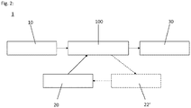
- FIG. 2 A flowchart of a method 1 according to an embodiment of the present invention is shown: Like in the Figure 2 can be seen, acquired sensor data 10 and an approximation model 20 for a target object by means of a Optimization method 100 processed. Model points of the approximation model are iteratively assigned to the sensor data and an overall deviation resulting from the assignment is calculated.
- the approximation model 20 includes proximity points and target object points (not shown).
- the approximation model is modified by receiving changed approximation points 22 '.
- the changed approximation points can be determined from a respective assignment made in the course of the optimization method 100 such that an associated overall deviation is reduced.
- the changed approximation points 22 ' preferably deviate from a basic model (which can be, for example, a construction model of the target object) by a predetermined range at most, so the change is limited.
- the optimization method 100 is carried out again using the modified approximation model, it being possible to use the same and / or modified method parameters.
- the approximation model can then be modified further.
- the position and position 30 of the target object with respect to a respective starting object can be determined with great robustness and accuracy on the basis of the resulting assignment.
- a method 1 for estimating a relative position and location of a target object with respect to a starting object For this purpose, sensor points 10 are acquired by scanning a surface of the target object and iteratively assigned to model points of an approximation model 20 by means of an optimization method 100. Its model points are distinguished in terms of their degree of familiarity: approximation points 22, 22 'of the approximation model 20 which are known to be unsafe are changed as part of the optimization process, whereas target object points 21 of the approximation model 20 which are known to be safe are retained.
Landscapes
- Engineering & Computer Science (AREA)
- Computer Vision & Pattern Recognition (AREA)
- Physics & Mathematics (AREA)
- General Physics & Mathematics (AREA)
- Theoretical Computer Science (AREA)
- Multimedia (AREA)
- Length Measuring Devices With Unspecified Measuring Means (AREA)
Abstract
Description
- Die vorliegende Erfindung betrifft ein Verfahren zum Schätzen einer relativen Position und Lage eines Zielobjekts in Bezug auf ein Ausgangsobjekt. Darüber hinaus betrifft die Erfindung einen steuerbaren Raumflugkörper mit einer Rechen- und Messeinheit, die dazu eingerichtet ist, ein derartiges Verfahren auszuführen.
- In Situationen, in denen ein vorbekanntes Zielobjekt ferngesteuert angenähert und dann bestimmten Prozeduren unterzogen werden soll, ist es im Allgemeinen wichtig, dass die jeweilige Position und Lage des Zielobjektes möglichst präzise erfasst wird. Stehen die genannten Informationen bereit, kann dann beispielsweise ein Roboter das Objekt greifen, um es an einen vorgesehenen Ort bzw. zu einer jeweiligen Einrichtung zu transportieren und/oder um sonstige Operationen wie beispielsweise Wartungsarbeiten an ihm vorzunehmen.
- Insbesondere treten derartige Situationen unter Wasser oder an sonstigen unzugänglichen bzw. unerreichbaren Orten auf der Erde oder auch im Weltraum auf, beispielsweise beim sogenannten "On-Orbit-Servicing", bei dem ein steuerbarer Raumflugkörper einen zu wartenden oder instandzusetzenden Satelliten anfliegt und dabei (beispielsweise auf den letzten ca. 50m) auf Grundlage einer ermittelten Position und/oder Lage ausgerichtet und navigiert wird.
- Sofern das jeweilige Zielobjekt keine visuellen Marken oder Retroreflektoren aufweist, die derartige Annäherungsprozesse erleichtern könnten, ist eine vorab bekannte, beispielsweise in Form von Konstruktionsdaten gegebene Gestalt des Objekts häufig das einzige Hilfsmittel, das bei einer Bestimmung von Position und Lage eines Objekts herangezogen werden kann. So können Sensordaten beispielsweise mit einem vorbekannten Modell des Objekts abgeglichen werden. Aus dem Ergebnis können eine relative Position und Lage des Objekts bestimmt werden.
- Zum Realisieren einer derartigen Vorgehensweise sind verschiedene Ansätze bekannt. So wird gemäß einer verbreiteten Methode ein Konturenmodell des jeweiligen Zielobjekt mit dem Ergebnis einer Kantenfilterung eines Kamerabildes verglichen. Die Lösung eines damit formulierten Optimierungsproblems liefert dann eine Position und Lage des Objekts.
- Alternative herkömmliche Verfahren bauen auf dreidimensionalen Punktwolken auf, die beispielsweise mittels jeweiliger Tiefenbildkameras, Stereokameras oder bildgebenden Lidar-Geräten aufgenommen werden. Die so gewonnenen Punktwolken werden dann mit einem räumlichen Modell des jeweiligen Zielobjekts verglichen. Die gesuchte relative Position und Lage kann dann mittels eines Optimierungsverfahrens (insbesondere des sogenannten "iterativen Closest-Point-Algorithmus ICP) bestimmt oder zumindest approximiert werden.
- Ein Nachteil derartiger herkömmlicher Verfahren besteht darin, dass die genaue Kenntnis über die Form des jeweiligen Zielobjekts vorausgesetzt wird; dies ist in der Realität in vielen Fällen jedoch nur unzulänglich der Fall. So sind beispielsweise Zielobjekte in Form von Satelliten im Weltraum meist großflächig mit einem flexiblen Isolationsmaterial umgeben, das bei Fertigung des jeweiligen Satelliten manuell um diesen gelegt wurde und ihn vor thermischen Einflüssen schützen soll. Derartige Isolationsschichten ändern eine aus Konstruktionsplänen und/oder CAD-Modellen bekannte Geometrie des Satelliten.
- Eine während einer Annäherung an den Zielsatelliten sensorisch aufgenommene Punktwolke kann daher nur mit eingeschränkter Genauigkeit mit den vorbekannten Konstruktionsdaten des teilweise vom Isolationsmaterial bedeckten Satelliten übereinstimmen. Die in der Realität auftretenden Abweichungen zwischen Isolationsschicht und Satellitenkörper, die beispielsweise im Bereich von etwa 2cm - 5cm liegen können, bedingen somit Fehler in der Positions- und Lagebestimmung und führen damit zu Ungenauigkeiten in der Navigation. Das Greifen bzw. Andocken wird dadurch erheblich erschwert.
- Der vorliegenden Erfindung liegt die Aufgabe zugrunde, eine Technik bereitzustellen, mit der die Genauigkeit bei der Bestimmung einer relativen Position und Lage eines Zielobjekts (in Bezug auf ein Ausgangsobjekt) erhöht wird.
- Die Aufgabe wird gelöst durch ein Verfahren gemäß Anspruch 1 und einen steuerbaren Raumflugkörper nach Anspruch 13. Vorteilhafte Ausführungsformen sind in den Unteransprüchen, der Beschreibung und den Figuren offenbart.
- Ein erfindungsgemäßes Verfahren dient dem Schätzen (und damit möglichst genauen Bestimmen) einer relativen Position und Lage eines Zielobjekts in Bezug auf ein Ausgangsobjekt; das Ausgangsobjekt kann dabei beispielsweise zumindest ein Teil eines (insbesondere unbemannten) Land- oder Wasserfahrzeugs oder Fluggeräts (z.B. eines steuerbaren Raumflugkörpers) sein oder zumindest ein Teil eines Roboters.
- Durch Abtasten einer Oberfläche des Zielobjekts werden bei einem erfindungsgemäßen Verfahren mehrere Sensorpunkten mittels mindestens eines Sensors akquiriert; der Sensor kann dabei mindestens ein Teil des Ausgangsobjekts sein oder in einer bekannten räumlichen Konstellation dazu angeordnet sein. In einem Optimierungsverfahren werden die akquirierten Sensorpunkte iterativ jeweils einem Modellpunkt eines Näherungsmodells für das Zielobjekt zugeordnet, bis eine Gesamtabweichung der akquirierten Sensorpunkte von den ihnen jeweils zugeordneten Modellpunkten minimiert ist oder unterhalb einer vorgegebenen Schranke liegt; die Gesamtabweichung kann dabei beispielsweise auf Grundlage der (euklidischen) Abstände der Sensorpunkte vom ihnen jeweils zugeordneten Modellpunkt und einer Summenbildung berechnet werden und/oder mittels einer integralbasierten Methode. Basierend auf einer aus dem Optimierungsverfahren resultierenden Zuordnung der Sensorpunkte wird dann die gesuchte relative Position und Lage des Zielobjekts geschätzt.
- Das Näherungsmodell enthält dabei erfindungsgemäß als Modellpunkte sowohl Punkte, in denen das Näherungsmodell einem präzise bekannten Oberflächenbereich des Zielobjekts entspricht (und die im Folgenden als "Zielobjektpunkte" bezeichnet werden), als auch (im Weiteren "Näherungspunkte" genannte) Punkte, in denen das Näherungsmodell als unsicher bekannt ist. Das Optimierungsverfahren umfasst ein einmaliges oder wiederholtes Modifizieren des Näherungsmodells. Dabei wird (jeweils) mindestens ein Teil der Näherungspunkte geändert, wohingegen die Zielobjektpunkte beibehalten werden.
- Ein erfindungsgemäßer Raumflugkörper ist steuerbar und umfasst mindestens einen Antrieb sowie eine Rechen- und Messeinheit mit mindestens einem Sensor. Die Rechen- und Messeinheit ist dabei dazu eingerichtet, die relative Position und Lage eines jeweiligen Zielobjekts in Bezug auf ein Ausgangsobjekt (das vorzugsweise zumindest ein Teil des Raumflugkörpers ist) gemäß einem erfindungsgemäßen Verfahren (in einer der in dieser Schrift offenbarten Ausführungsformen) zu schätzen.
- Gemäß vorteilhaften Ausführungsformen umfasst ein derartiger Raumflugkörper mindestens ein Greifelement, das dazu eingerichtet ist, zum Zielobjekt hingeführt zu werden und dieses dann auf Grundlage einer geschätzten relativen Position und Lage des Zielobjekt zu greifen.
- Erfindungsgemäß wird somit für die Schätzung ein adaptives Näherungsmodell verwendet, dessen Punkte hinsichtlich ihres Bekanntheitsgrades unterschieden werden. Auf diese Weise kann bei der Positions- und Lageschätzung berücksichtigt werden, dass das Näherungsmodell einerseits vorbekannte Bereiche des Zielobjekts präzise beschreibt, von denen jeweilige Sensorpunkte lediglich aufgrund eines Sensormessrauschens abweichen, dass aber in anderen Bereichen des Näherungsmodells sowohl die Modellpunkte als auch zugehörige Sensorpunkte ungenau sein können. In diesen Bereichen wird das Näherungsmodell dann modifiziert und kann so nach und nach (und insbesondere unter Verwendung der akquirierten Sensorpunkte) einer tatsächlichen äußeren Gestalt des Zielobjekts in dessen jeweils aktueller Position bzw. Lage angeglichen werden, die damit besonders genau bzw. zutreffend geschätzt werden kann.
- Selbst bei nur ungenauer Kenntnis über die äußere Gestalt des Zielobjekts kann mittels der vorliegenden Erfindung somit präzise eine jeweilige Position und Lage des Zielobjekts bestimmt werden. Insbesondere kann daher in entsprechenden Anwendungen auf aufwendige Greifmechanismen mit besonders nachgiebigen und toleranten Andockmechanismen, die herkömmlicherweise zur Kompensation von Ungenauigkeiten in den Positions- und Lagedaten eingesetzt werden, verzichtet werden.
- Der mindestens eine Sensor kann beispielsweise einen bildgebenden Lidar und/oder Radar umfassen und/oder eine Kamera, insbesondere eine Stereokamera und/oder eine Tiefenbildkamera. Die Sensorpunkte können zwei- oder dreidimensionale Daten sein, die beispielsweise Koordinatenwerte für jeweils erfasste Punkte der Oberfläche des Zielobjekts enthalten können. Analog kann das Näherungsmodell (in seinen jeweiligen Varianten / Modifikationen) zwei- oder dreidimensional sein. Vorzugsweise stimmen die Dimensionen der Sensorpunkte und des Näherungsmodells überein.
- Gemäß vorteilhafter Ausführungsformen eines erfindungsgemäßen Verfahrens wird durch zumindest einen Teil der Zielobjektpunkte des Näherungsmodells wenigstens eine starre Oberfläche des Zielobjekts nachgebildet.
- Eine derartige starre Oberfläche ist insbesondere weitgehend unabhängig von Umgebungseinflüssen und kann in einer festgelegten, stabilen Form gefertigt werden. Ein vorzugsweise auf Grundlage von Konstruktionsdaten erstelltes Näherungsmodell kann daher einer solchen Oberfläche sehr genau entsprechen und dort somit als zuverlässig gelten.
- Wenigstens ein Teil der Näherungspunkte des Näherungsmodells kann gemäß vorteilhaften Ausführungsformen mindestens eine bewegliche oder sogar flexible Oberfläche des Zielobjekts nachbilden (bzw. approximieren). Eine solche Oberfläche kann irregulär ausgebildet sein und/oder kaum vorherzusehenden sich auf ihre Form auswirkenden Einflüssen unterliegen, so dass ihre Modellierung unsicher sein kann.
- In mindestens einem Teil der Zielobjektpunkte stimmt das Näherungsmodell (in seinen verschiedenen Modifikationen) vorzugsweise mit einem Konstruktionsmodell (beispielsweise einem CAD-Modell) zumindest eines Teils des Zielobjekts überein.
- Gemäß speziellen Ausführungsbeispielen der vorliegenden Erfindung ist das Zielobjekt ein Satellit, der insbesondere teilweise von mindestens einem Schutz- und/oder Isoliermaterial (z.B. einem Multilayer-Insulation-Material (MLI)) umhüllt sein kann.
- Zielobjektpunkte des Näherungsmodells können bei derartigen Ausführungsformen Punkte umfassen, in denen das Näherungsmodell mindestens einen Bereich des Satelliten repräsentiert, von dem (insbesondere bei Anwendung des Optimierungsverfahrens) bekannt ist, dass er frei von derartigem Schutzmaterial ist: Ein derartiger Bereich kann beispielsweise eine mechanische Schnittstelle (beispielsweise einen Launch-Adapter-Ring) zur Verbindung des Satelliten (bei seinem Transport) mit einer Trägerrakete umfassen und/oder eine Düse eines Apogäumsmotors des Satelliten und/oder mindestens eine Baugruppe eines Lagetriebwerkes.
- Gemäß vorteilhaften Ausführungsformen der vorliegenden Erfindung umfasst das Optimierungsverfahren ein Durchführen eines Iterative-Closest-Point-Algorithmus' mit gleichbleibendem Näherungsmodell (so dass also während dieses Durchführens keine Modifikation des Näherungsmodells erfolgt). Eine aus dem Iterative-Closest-Point-Algorithmus resultierende Zuordnung der akquirierten Sensorpunkte liefert dann vorzugsweise die Grundlage, aufgrund deren das Näherungsmodell zumindest einmal wenigstens in einem Teil seiner Näherungspunkte modifiziert wird. Auf diese Weise können zunächst die Sensorpunkte und das Näherungsmodell mittels durch den Iterative-Closest-Point-Algorithmus bestimmte Transformationen (insbesondere Rotationen und/oder Translationen) in möglichst gute Deckung miteinander gebracht werden, ehe das Näherungsmodell in den (als unsicher bekannten) Näherungspunkten modifiziert und die Übereinstimmung durch die Berücksichtigung der Schwächen des Näherungsmodells so weiter verbessert werden können.
- Alternativ oder zusätzlich kann das Optimierungsverfahren beispielsweise ein Anwenden eines Coherent-Point-Drift-Verfahren, eines Robust-Point-Matching-Verfahrens, eines Kernel-Correlationsverfahrens, eines Simulated-Annealing-Verfahrens und/oder sonstiger Optimierungsalgorithmen umfassen. Gemäß einer vorteilhaften Ausführungsform der vorliegenden Erfindung umfasst das Optimierungsverfahren das Anwenden eines künstlichen neuronalen Netzes. Dies erlaubt insbesondere eine besonders effiziente fortschreitende Reduktion von Abweichungen zwischen dem Zielobjekt und einer jeweiligen Version des (modifizierten) Näherungsmodells.
- Gemäß vorteilhaften Ausführungsformen umfasst ein erfindungsgemäßes Verfahren ein weiteres Akquirieren von Sensorpunkten durch Abtasten der Oberfläche oder einer anderen Oberfläche des Zielobjekts mittels des mindestens eines Sensors. Die dadurch akquirierten Sensorpunkte werden im Folgenden als "weitere Sensorpunkte" (oder auch "weitere Mehrzahl an Sensorpunkten") bezeichnet. Vorzugsweise umfasst eine solche Ausführungsform zudem ein weiteres Durchführen des Optimierungsverfahrens. Beim Durchführen eines (dem weiteren) nachfolgenden Optimierungsverfahrens kann dann mit einer Version des Näherungsmodells gestartet werden, die sich aus dem (zuvor erfolgten) weiteren Durchführen des Optimierungsverfahrens mit den weiteren Sensorpunkten ergeben hat. Auf diese Weise kann das Näherungsmodell anhand der nachfolgend erfassten Sensorpunkte weiterentwickelt und verbessert werden.
- Die weiteren und die nachfolgend erfassten Sensorpunkte können bei derartigen Ausführungsformen in voneinander verschiedenem (ggf. mittleren) Abstand vom Zielobjekt und/oder aus voneinander verschiedenen Richtungen akquiriert werden. Insbesondere kann sich der mindestens eine Sensor zwischen dem Akquirieren von weiteren und nachfolgenden Sensorpunkten also relativ zum Zielobjekt bewegen, beispielsweise auf dieses zu. In das auf den weiteren und nachfolgenden Sensorpunkten beruhende nachfolgende Näherungsmodell fließen dann also vorteilhaft verschiedene Abstände und Perspektiven, insbesondere Sichtfelder ein. Dadurch kann das Näherungsmodell besonders gut an die tatsächliche äußere Geometrie des Zielobjekts angepasst werden.
- Gemäß vorteilhaften Ausführungsformen der vorliegenden Erfindung erfolgt das Schätzen der relativen Position und Lage des Zielobjekts mehrmals: Insbesondere kann das Verfahren ein weiteres Schätzen der relativen Position und Lage auf Grundlage einer aus dem weiteren Durchführen resultierenden Zuordnung der Sensorpunkte umfassen. Ein nachfolgendes Schätzen der Position und Lage kann dann außer auf der Zuordnung, die sich dem nachfolgenden Durchführen ergibt, auf dem weiteren Schätzen beruhen, insbesondere kann beim nachfolgenden Schätzen das (frühere) Ergebnis des weiteren Schätzens verwendet werden.
- Beispielsweise in Situationen, in denen beim nachfolgenden Schätzen aufgrund einer zu großen Nähe wesentliche Elemente des Zielobjekts aus dem Sichtfeld verschwunden sind, kann dadurch insbesondere die Lageschätzung verbessert werden.
- Das Ändern der Näherungspunkte des Näherungsmodells erfolgt vorzugsweise jeweils innerhalb einer festgelegten Spanne um Punkte eines vorgegebenen Grundmodells. Das Grundmodell kann dabei beispielsweise durch ein Konstruktionsmodell des Zielobjekts gegeben sein. Durch die Spanne kann beispielsweise festgelegt sein, dass geänderte Näherungspunkte höchstens +/- 5cm, höchstens +/- 3cm oder höchstens +/- 2cm von dem Grundmodell abweichen. Auf diese Weise kann die Adaptivität des Näherungsmodells kontrolliert und in vorgegebenen Grenzen gehalten werden. Insbesondere können damit Fehlentwicklungen beispielsweise infolge eines Sensordefekts verhindert werden.
- Die Spanne kann während des Durchführens des Optimierungsverfahrens geändert, insbesondere verkleinert werden, so dass dann also bei einem ersten Modifizieren des Näherungsmodells andere Schranken gelten als bei einem späteren Modifizieren.
- Alternativ oder zusätzlich können - in entsprechenden Ausführungsformen, die ein mehrmaliges Durchführen des Optimierungsverfahrens mit jeweiligen Sensorpunkten umfassen - bei einem ersten Durchführen eine andere, insbesondere eine größere Spanne festgelegt sein als bei einem späteren Durchführen. Dies ermöglicht eine genaue Schätzung auch dann, wenn sich das Zielobjekt und das Ausgangsobjekt relativ zueinander bewegen und beispielsweise beim späteren Durchführen des Optimierungsverfahrens aufgrund der geänderten Perspektive ein Teil oder alle Zielobjektpunkte nicht mehr vom mindestens einen Sensor erfasst werden können.
- Im Folgenden werden Aspekte bevorzugter Ausführungsbeispiele der vorliegenden Erfindung anhand von Zeichnungen näher erläutert. Bezugszeichen für einander entsprechende Elemente sind dabei figurenübergreifend verwendet.
- Es zeigen schematisch:
- Figur 1 a - c :
- eine Illustration von Schritten eines exemplarischen Optimierungsverfahrens als Teil eines erfindungsgemäßen Verfahrens;
- Figur 2:
- ein Ablaufdiagramm eines Verfahrens gemäß einer Ausführungsform der vorliegenden Erfindung.
- In den
Figuren 1a - 1c ist eine Optimierungsverfahren erläutert, wie es in einem erfindungsgemäßen Verfahren Anwendung findet. - Dabei wird eine Mehrzahl von Sensorpunkten 10 verwendet, die zuvor mittels mindestens eines Sensors durch Abtasten einer Oberfläche eines jeweiligen Zielobjekts akquiriert wurden (nicht dargestellt). Die einzelnen Sensorpunkte 10 der so erhaltenen Punktwolke unterliegen Messungenauigkeiten und enthalten keine Information darüber, welche Oberflächenbereiche des Zielobjekts durch sie erfasst wurden. Zudem ist die Geometrie der Oberfläche dabei nur teilweise präzise bekannt (z.B. durch Konstruktionsdaten des Zielobjekts). Dem Verfahren liegt nun das Problem zugrunde, dass gleichwohl anhand der Sensorpunkte geschlossen bzw. abgeschätzt werden soll, wie das Zielobjekt angeordnet sein muss (wie also seine Position und Lage in Bezug auf ein Ausgangsobjekt, z.B. den Sensor sind), damit der Sensor diese Sensorpunkte akquirieren konnte.
- Erfindungsgemäß wird dazu zumindest ein Bereich eines adaptiven Näherungsmodells 20 für das Zielobjekt nach und nach mit dem Sensorpunkten (d.h. den zugehörigen Daten) in Einklang gebracht:
InFigur 1a ist (mittels Pfeilen) illustriert, dass den einzelnen Sensorpunkten 10 jeweils ein Modellpunkt des Näherungsmodells 20 zugeordnet wird; das Näherungsmodell kann insbesondere ein Konstruktionsmodell (z.B. ein CAD-Modell) des Zielobjekts sein. Durch Verdrehen und/oder Verschieben von Näherungsmodell und Sensorpunkten relativ zueinander wird im Wege des (automatisierten) Optimierungsverfahrens versucht, das Näherungsmodell 20 und die Sensorpunktwolke möglichst gut miteinander in Deckung zu bringen, die Gesamtabweichung zwischen den Sensorpunkten 10 und den ihnen jeweils zugeordneten Modellpunkten also zu minimieren oder unterhalb eine vorgegebene Schranke zu senken. Dieses Vorgehen kann beispielsweise die Anwendung eines Iterative-Closest-Point-Algorithmus umfassen. Die Gesamtabweichung kann insbesondere auf Grundlage der euklidischen Abstände der Sensorpunkte 10 von den ihnen jeweils zugeordneten Modellpunkten bestimmt werden, beispielsweise kann dabei die Summe der jeweils quadrierten Abstände berechnet werden. - Erfindungsgemäß liegt dem verwendeten Optimierungsverfahren eine unterschiedliche Bewertung der Modellpunkte des Näherungsmodells 20 zugrunde: Dieses umfasst demnach Zielobjektpunkte 21, in denen das Näherungsmodell einem präzise bekannten Oberflächenbereich des Zielobjekts entspricht, sowie Näherungspunkte 22, in denen das Näherungsmodell als unsicher bekannt ist, beispielsweise weil in ihm nicht berücksichtigt ist, dass das Zielobjekt im Bereich der Näherungspunkte mit einem zusätzlichen Material wie z.B. einer Isolations- und/oder Schutzschicht bedeckt ist.
- In
Figur 1b ist dargestellt, wie die Sensorpunkte 10 und das Näherungsmodell 20 (im Vergleich zurFigur 1a ) relativ zueinander verschoben sind. Dabei wurde die Punktwolke der Sensorpunkte 10 möglichst genau den Zielobjektpunkten 21 des Näherungsmodells 20 angenähert. - In den Näherungspunkten 22 hingegen wurde das Näherungsmodell dabei nicht mit den Sensorpunkten 10 in Deckung gebracht.
- Die dort vorhandenen Abweichungen werden dann durch Ändern mindestens eines Teils der Näherungspunkte 22 reduziert; die Zielobjektpunkte 21 bleiben dabei erhalten: In
Figur 1c ist das derart modifizierte Näherungsmodell 20 mit den beibehaltenen Zielobjektpunkten 21 und den geänderten Näherungspunkten 22' dargestellt. Wie aus derFigur 1c ersichtlich ist, kann auf diese Weise eine hohe Übereinstimmung von (modifiziertem) Näherungsmodell und Sensorpunkten 10 erreicht werden. Die Sensorpunkte 10 können damit jeweiligen Modellpunkten auf dem modifizierten Näherungsmodell 20 so zugeordnet werden, dass eine Gesamtabweichung minimiert wird. Auf Grundlage einer solchen Zuordnung können dann Position und Lage des Zielobjekts realitätsnah geschätzt werden. - In
Figur 2 ist ein Ablaufdiagramm eines Verfahrens 1 gemäß einer Ausführungsform der vorliegenden Erfindung dargestellt:
Wie in derFigur 2 zu erkennen ist, werden akquirierte Sensordaten 10 und ein Näherungsmodell 20 für ein Zielobjekt mittels eines Optimierungsverfahrens 100 verarbeitet. Dabei werden den Sensordaten iterativ Modellpunkte des Näherungsmodells zugeordnet und eine jeweils aus der Zuordnung resultierende Gesamtabweichung berechnet. - Das Näherungsmodell 20 umfasst Näherungspunkte und Zielobjektpunkte (nicht dargestellt). Zum Optimieren bzw. Verbessern der Zuordnung im Sinne einer Verminderung der Gesamtabweichung wird das Näherungsmodell modifiziert, indem es geänderte Näherungspunkte 22' erhält. Die geänderten Näherungspunkte können dabei aus einer jeweiligen, im Wege des Optimierungsverfahrens 100 vorgenommenen Zuordnung so bestimmt werden, dass eine zugehörige Gesamtabweichung reduziert wird. Dabei weichen die geänderten Näherungspunkte 22' vorzugsweise höchstens um eine vorgegebene Spanne von einem Grundmodell (das beispielsweise ein Konstruktionsmodell des Zielobjekts sein kann) ab, die Änderung ist also limitiert.
- Das Optimierungsverfahren 100 wird mit dem modifizierten Näherungsmodell erneut durchgeführt, wobei gleiche und/modifizierte Verfahrensparameter verwendet werden können. Das Näherungsmodell kann dann weiter modifiziert werden.
- Liegt die Gesamtabweichung nach einem oder mehreren derartigen Durchläufen und ggf. Modifikationen unterhalb einer vorgegebenen Schranke, können anhand der sich ergebenden Zuordnung die Position und Lage 30 des Zielobjekts in Bezug auf ein jeweiliges Ausgangsobjekt mit hoher Robustheit und Genauigkeit bestimmt werden.
- Offenbart ist ein Verfahren 1 zum Schätzen einer relativen Position und Lage eines Zielobjekts in Bezug auf ein Ausgangsobjekt. Dazu werden durch Abtasten einer Oberfläche des Zielobjekts Sensorpunkte 10 akquiriert und mittels eines Optimierungsverfahrens 100 iterativ Modellpunkten eines Näherungsmodells 20 zugeordnet. Dessen Modellpunkte werden hinsichtlich ihres Bekanntheitsgrades unterschieden: Als unsicher bekannte Näherungspunkte 22, 22' des Näherungsmodells 20 werden im Rahmen des Optimierungsverfahrens geändert, wohingegen als sicher bekannte Zielobjektpunkte 21 des Näherungsmodells 20 dabei beibehalten werden.
-
- 1
- erfindungsgemäßes Verfahren gemäß einer exemplarischen Ausführungsform
- 10
- Sensorpunkte
- 20
- Näherungsmodell
- 21
- Zielobjektpunkte
- 22
- Näherungspunkte
- 22'
- geänderte Näherungspunkte
- 30
- Position und Lage
- 100
- Optimierungsverfahren
Claims (14)
- Verfahren (1) zum Schätzen einer relativen Position und Lage eines Zielobjekts in Bezug auf ein Ausgangsobjekt, wobei das Verfahren umfasst:- Akquirieren einer Mehrzahl von Sensorpunkten (10) durch Abtasten einer Oberfläche des Zielobjekts mittels mindestens eines Sensors;- Durchführen eines Optimierungsverfahrens (100), in dem die akquirierten Sensorpunkte (10) iterativ jeweils einem Modellpunkt eines Näherungsmodells (20) für das Zielobjekt zugeordnet werden, bis eine Gesamtabweichung der akquirierten Sensorpunkte von den ihnen jeweils zugeordneten Modellpunkten minimiert ist oder unterhalb einer vorgegebenen Schranke liegt; und- Schätzen der relativen Position und Lage (20) des Zielobjekts auf Grundlage einer aus dem Optimierungsverfahren resultierenden Zuordnung der Sensorpunkte;dadurch gekennzeichnet,
dass das Näherungsmodell (20) als Modellpunkte Zielobjektpunkte (21) umfasst, in denen das Näherungsmodell einem präzise bekannten Oberflächenbereich des Zielobjekts entspricht, sowie Näherungspunkte (22, 22'), in denen das Näherungsmodell als unsicher bekannt ist,
und dass das Optimierungsverfahren (100) ein einmaliges oder wiederholtes Modifizieren des Näherungsmodells durch Ändern mindestens eines Teils seiner Näherungspunkte (22, 22') bei Festhalten an den Zielobjektpunkten (21) umfasst. - Verfahren gemäß Anspruch 1, wobei das Optimierungsverfahren (100) mindestens ein Durchführen eines Iterative-Closest-Point Algorithmus' mit gleichbleibendem Näherungsmodell umfasst und wobei das Modifizieren des Näherungsmodells zumindest einmal auf Grundlage einer aus dem Iterative-Closest-Point Algorithmus resultierenden Zuordnung der akquirierten Sensorpunkte (10) erfolgt.
- Verfahren gemäß einem der Ansprüche 1 oder 2, wobei das Optimierungsverfahren (100) ein Anwenden eines künstlichen neuronalen Netzes umfasst.
- Verfahren gemäß einem der vorhergehenden Ansprüche, wobei das Ändern der Näherungspunkte (22, 22') jeweils innerhalb einer festgelegten Spanne um Punkte eines vorgegebenen Grundmodells des Zielobjekts erfolgt.
- Verfahren gemäß einem der vorhergehenden Ansprüche, wobei das Akquirieren der Mehrzahl an Sensorpunkten (10) ein nachfolgendes Akquirieren und das Durchführen des Optimierungsverfahrens (100) ein nachfolgendes Durchführen sind,
und wobei das Verfahren zudem- vor dem nachfolgenden ein weiteres Akquirieren einer weiteren Mehrzahl an Sensorpunkten durch Abtasten der Oberfläche oder einer anderen Oberfläche des Zielobjekts mittels des mindestens eines Sensors sowie- vor dem nachfolgenden ein weiteres Durchführen des Optimierungsverfahrensumfasst,
und wobei das Durchführen des nachfolgenden Optimierungsverfahrens mit einer Version des Näherungsmodells startet, die sich aus der Durchführung des weiteren Optimierungsverfahrens mit der weiteren Mehrzahl an Sensorpunkten ergibt. - Verfahren gemäß Anspruch 5, wobei die Mehrzahl an Sensorpunkten (10) und die weitere Mehrzahl an Sensorpunkten in voneinander verschiedenem Abstand des mindestens einen Sensors vom Zielobjekt akquiriert werden.
- Verfahren gemäß einem der Ansprüche 5 oder 6, wobei eine für das das Ändern der Näherungspunkte (22, 22') jeweils festgelegte Spanne beim nachfolgenden Durchführen des Optimierungsverfahrens kleiner ist als oder genauso groß ist wie beim weiteren Durchführen.
- Verfahren gemäß einem der Ansprüche 5 bis 7, wobei das Schätzen der relativen Position und Lage (30) des Zielobjekts ein nachfolgendes Schätzen ist und zudem auf Grundlage einer Positions- und Lageschätzung erfolgt, die auf einer sich aus dem weiteren Durchführen des Optimierungsverfahrens ergebenden Zuordnung beruht.
- Verfahren gemäß einem der vorhergehenden Ansprüche, wobei die Näherungspunkte (22, 22') des Näherungsmodells jeweils eine bewegliche oder sogar flexible Oberfläche des Zielobjekts nachbilden.
- Verfahren gemäß einem der vorhergehenden Ansprüche, wobei die Zielobjektpunkte (21) des Näherungsmodells jeweils eine starre Oberfläche des Zielobjekts nachbilden.
- Verfahren gemäß einem der vorhergehenden Ansprüche, wobei die Sensordaten (10) und das Näherungsmodell (20) jeweils zweidimensional oder jeweils dreidimensional sind.
- Verfahren gemäß einem der vorhergehenden Ansprüche, wobei das Zielobjekt ein teilweise von einer Multi-Layer-Isolationsschicht umgebener Satellit und/oder wobei das Ausgangsobjekt mindestens ein Teil eines steuerbaren Raumflugkörpers ist.
- Steuerbarer Raumflugkörper, der mindestens einen Antrieb und eine Rechen- und Messeinheit mit mindestens einem Sensor umfasst, wobei die Rechen- und Messeinheit dazu eingerichtet ist, ein Verfahren (1) gemäß einem der vorhergehenden Ansprüche auszuführen.
- Raumflugkörper gemäß Anspruch 13, der zudem mindestens ein Greifelement umfasst und dazu eingerichtet ist, ein jeweiliges Zielobjekt auf Grundlage einer geschätzten relativen Position und Lage (30) des Zielobjekts in Bezug auf den Raumflugkörper zu greifen.
Priority Applications (1)
| Application Number | Priority Date | Filing Date | Title |
|---|---|---|---|
| EP19154869.2A EP3690816B1 (de) | 2019-01-31 | 2019-01-31 | Schätzen einer relativen position und lage eines zielobjekts in bezug auf ein ausgangsobjekt |
Applications Claiming Priority (1)
| Application Number | Priority Date | Filing Date | Title |
|---|---|---|---|
| EP19154869.2A EP3690816B1 (de) | 2019-01-31 | 2019-01-31 | Schätzen einer relativen position und lage eines zielobjekts in bezug auf ein ausgangsobjekt |
Publications (2)
| Publication Number | Publication Date |
|---|---|
| EP3690816A1 true EP3690816A1 (de) | 2020-08-05 |
| EP3690816B1 EP3690816B1 (de) | 2022-08-17 |
Family
ID=65276057
Family Applications (1)
| Application Number | Title | Priority Date | Filing Date |
|---|---|---|---|
| EP19154869.2A Active EP3690816B1 (de) | 2019-01-31 | 2019-01-31 | Schätzen einer relativen position und lage eines zielobjekts in bezug auf ein ausgangsobjekt |
Country Status (1)
| Country | Link |
|---|---|
| EP (1) | EP3690816B1 (de) |
Citations (2)
| Publication number | Priority date | Publication date | Assignee | Title |
|---|---|---|---|---|
| US20120320053A1 (en) * | 2010-02-25 | 2012-12-20 | Canon Kabushiki Kaisha | Position and orientation estimation method and apparatus therefor |
| US20150235380A1 (en) * | 2012-11-19 | 2015-08-20 | Ihi Corporation | Three-dimensional object recognition device and three-dimensional object recognition method |
-
2019
- 2019-01-31 EP EP19154869.2A patent/EP3690816B1/de active Active
Patent Citations (2)
| Publication number | Priority date | Publication date | Assignee | Title |
|---|---|---|---|---|
| US20120320053A1 (en) * | 2010-02-25 | 2012-12-20 | Canon Kabushiki Kaisha | Position and orientation estimation method and apparatus therefor |
| US20150235380A1 (en) * | 2012-11-19 | 2015-08-20 | Ihi Corporation | Three-dimensional object recognition device and three-dimensional object recognition method |
Non-Patent Citations (2)
| Title |
|---|
| A MASSON: "AIRBUS DS VISION BASED NAVIGATION SOLUTIONS TESTED ON LIRIS EXPERIMENT DATA", PROC. 7TH EUROPEAN CONFERENCE ON SPACE DEBRIS, 18 April 2017 (2017-04-18), Darmstadt, Germany, pages 1 - 8, XP055599318 * |
| OPROMOLLA ROBERTO ET AL: "A review of cooperative and uncooperative spacecraft pose determination techniques for close-proximity operations", PROGRESS IN AEROSPACE SCIENCES, OXFORD, GB, vol. 93, 21 July 2017 (2017-07-21), pages 53 - 72, XP085191302, ISSN: 0376-0421, DOI: 10.1016/J.PAEROSCI.2017.07.001 * |
Also Published As
| Publication number | Publication date |
|---|---|
| EP3690816B1 (de) | 2022-08-17 |
Similar Documents
| Publication | Publication Date | Title |
|---|---|---|
| EP2916106B1 (de) | Verfahren zur Positions- und Lagebestimmung mittels virtueller Referenzbilder | |
| DE102016211129A1 (de) | Verfahren zum Überprüfen einer Kollision zwischen zwei fahrerlosen Transportfahrzeugen, fahrerloses Transportfahrzeug und System mit mehreren fahrerlosen Transportfahrzeugen | |
| DE102019206444A1 (de) | Maschinelles Lernen einer Objekterkennung mithilfe einer robotergeführten Kamera | |
| EP2381207B1 (de) | 3D-Zielvermessung und Zieleinweisung aus IR-Daten | |
| DE102019100820A1 (de) | Verfahren und Vorrichtung zur Inspektion schwer erreichbarer Komponenten | |
| DE102018207421A1 (de) | Verfahren und System zum Ermitteln einer erwarteten Vorrichtungskontur | |
| DE69829091T2 (de) | Messungsgerät | |
| EP4239277A1 (de) | Vorrichtung und verfahren zur zielübergabe | |
| DE102005035746B4 (de) | Verfahren zur Bestimmung einer Relativposition einer mobilen Einheit durch Vergleich von Scans einer Umgebung und mobile Einheit | |
| EP3387375B1 (de) | Verfahren zur erstellung einer tiefenkarte | |
| EP4225537A1 (de) | Kalibrierungsverfahren zur automatisierten kalibrierung von kamera zu medizinischem roboter und chirurgisches assistenzsystem | |
| DE102018128535A1 (de) | Trainieren eines künstlichen neuronalen Netzwerks mit durch Sensoren eines Fahrzeugs erfassten Daten | |
| WO2021233674A1 (de) | Verfahren zum ermitteln einer ausgangspose eines fahrzeugs | |
| EP3690816B1 (de) | Schätzen einer relativen position und lage eines zielobjekts in bezug auf ein ausgangsobjekt | |
| EP3797936A1 (de) | Verfahren zum präzisieren einer position und/oder orientierung eines gerätekopfes | |
| EP1915239B1 (de) | Verfahren zum erzeugen eines umgebungsbildes | |
| DE102017123195A1 (de) | System und Verfahren zum Navigieren eines Flugzeugs in einer Halle | |
| DE102021200569A1 (de) | Vorrichtung und Verfahren zum Trainieren eines Gaußprozess-Zustandsraummodells | |
| DE102014108873B4 (de) | Verfahren zum Bestimmen einer aktuellen Position einer Landeeinrichtung | |
| EP3797935A1 (de) | Verfahren zum präzisieren einer position und/oder orientierung eines gerätekopfes | |
| DE102019207410A1 (de) | Verfahren und Vorrichtung für eine automatisierte Beeinflussung eines Aktuators | |
| DE102023107422A1 (de) | Verbesserte navigation, lokalisierung und bahnplanung für autonome roboter | |
| DE102021123124B4 (de) | Verfahren zum Steuern eines unbemannten Fluggeräts für einen Inspektionsflug zum Inspizieren eines Objekts und unbemanntes Inspektionsfluggerät | |
| DE102014017904A1 (de) | Verfahren und Vorrichtung zur Detektion erhabener Objekte und Verfahren zur Unterstützung eines Fahrers beim Führen eines Fahrzeugs | |
| DE102006036346A1 (de) | Verfahren zur automatisierten 3-D-Objekterkennung und Lagebestimmung |
Legal Events
| Date | Code | Title | Description |
|---|---|---|---|
| PUAI | Public reference made under article 153(3) epc to a published international application that has entered the european phase |
Free format text: ORIGINAL CODE: 0009012 |
|
| STAA | Information on the status of an ep patent application or granted ep patent |
Free format text: STATUS: THE APPLICATION HAS BEEN PUBLISHED |
|
| AK | Designated contracting states |
Kind code of ref document: A1 Designated state(s): AL AT BE BG CH CY CZ DE DK EE ES FI FR GB GR HR HU IE IS IT LI LT LU LV MC MK MT NL NO PL PT RO RS SE SI SK SM TR |
|
| AX | Request for extension of the european patent |
Extension state: BA ME |
|
| STAA | Information on the status of an ep patent application or granted ep patent |
Free format text: STATUS: REQUEST FOR EXAMINATION WAS MADE |
|
| 17P | Request for examination filed |
Effective date: 20201218 |
|
| RBV | Designated contracting states (corrected) |
Designated state(s): AL AT BE BG CH CY CZ DE DK EE ES FI FR GB GR HR HU IE IS IT LI LT LU LV MC MK MT NL NO PL PT RO RS SE SI SK SM TR |
|
| GRAP | Despatch of communication of intention to grant a patent |
Free format text: ORIGINAL CODE: EPIDOSNIGR1 |
|
| STAA | Information on the status of an ep patent application or granted ep patent |
Free format text: STATUS: GRANT OF PATENT IS INTENDED |
|
| INTG | Intention to grant announced |
Effective date: 20220321 |
|
| GRAS | Grant fee paid |
Free format text: ORIGINAL CODE: EPIDOSNIGR3 |
|
| GRAA | (expected) grant |
Free format text: ORIGINAL CODE: 0009210 |
|
| STAA | Information on the status of an ep patent application or granted ep patent |
Free format text: STATUS: THE PATENT HAS BEEN GRANTED |
|
| AK | Designated contracting states |
Kind code of ref document: B1 Designated state(s): AL AT BE BG CH CY CZ DE DK EE ES FI FR GB GR HR HU IE IS IT LI LT LU LV MC MK MT NL NO PL PT RO RS SE SI SK SM TR |
|
| REG | Reference to a national code |
Ref country code: CH Ref legal event code: EP |
|
| REG | Reference to a national code |
Ref country code: DE Ref legal event code: R096 Ref document number: 502019005298 Country of ref document: DE |
|
| REG | Reference to a national code |
Ref country code: IE Ref legal event code: FG4D Free format text: LANGUAGE OF EP DOCUMENT: GERMAN |
|
| REG | Reference to a national code |
Ref country code: AT Ref legal event code: REF Ref document number: 1512666 Country of ref document: AT Kind code of ref document: T Effective date: 20220915 |
|
| REG | Reference to a national code |
Ref country code: NL Ref legal event code: MP Effective date: 20220817 |
|
| REG | Reference to a national code |
Ref country code: LT Ref legal event code: MG9D |
|
| PG25 | Lapsed in a contracting state [announced via postgrant information from national office to epo] |
Ref country code: SE Free format text: LAPSE BECAUSE OF FAILURE TO SUBMIT A TRANSLATION OF THE DESCRIPTION OR TO PAY THE FEE WITHIN THE PRESCRIBED TIME-LIMIT Effective date: 20220817 Ref country code: RS Free format text: LAPSE BECAUSE OF FAILURE TO SUBMIT A TRANSLATION OF THE DESCRIPTION OR TO PAY THE FEE WITHIN THE PRESCRIBED TIME-LIMIT Effective date: 20220817 Ref country code: PT Free format text: LAPSE BECAUSE OF FAILURE TO SUBMIT A TRANSLATION OF THE DESCRIPTION OR TO PAY THE FEE WITHIN THE PRESCRIBED TIME-LIMIT Effective date: 20221219 Ref country code: NO Free format text: LAPSE BECAUSE OF FAILURE TO SUBMIT A TRANSLATION OF THE DESCRIPTION OR TO PAY THE FEE WITHIN THE PRESCRIBED TIME-LIMIT Effective date: 20221117 Ref country code: NL Free format text: LAPSE BECAUSE OF FAILURE TO SUBMIT A TRANSLATION OF THE DESCRIPTION OR TO PAY THE FEE WITHIN THE PRESCRIBED TIME-LIMIT Effective date: 20220817 Ref country code: LV Free format text: LAPSE BECAUSE OF FAILURE TO SUBMIT A TRANSLATION OF THE DESCRIPTION OR TO PAY THE FEE WITHIN THE PRESCRIBED TIME-LIMIT Effective date: 20220817 Ref country code: LT Free format text: LAPSE BECAUSE OF FAILURE TO SUBMIT A TRANSLATION OF THE DESCRIPTION OR TO PAY THE FEE WITHIN THE PRESCRIBED TIME-LIMIT Effective date: 20220817 Ref country code: FI Free format text: LAPSE BECAUSE OF FAILURE TO SUBMIT A TRANSLATION OF THE DESCRIPTION OR TO PAY THE FEE WITHIN THE PRESCRIBED TIME-LIMIT Effective date: 20220817 |
|
| PG25 | Lapsed in a contracting state [announced via postgrant information from national office to epo] |
Ref country code: PL Free format text: LAPSE BECAUSE OF FAILURE TO SUBMIT A TRANSLATION OF THE DESCRIPTION OR TO PAY THE FEE WITHIN THE PRESCRIBED TIME-LIMIT Effective date: 20220817 Ref country code: IS Free format text: LAPSE BECAUSE OF FAILURE TO SUBMIT A TRANSLATION OF THE DESCRIPTION OR TO PAY THE FEE WITHIN THE PRESCRIBED TIME-LIMIT Effective date: 20221217 Ref country code: HR Free format text: LAPSE BECAUSE OF FAILURE TO SUBMIT A TRANSLATION OF THE DESCRIPTION OR TO PAY THE FEE WITHIN THE PRESCRIBED TIME-LIMIT Effective date: 20220817 Ref country code: GR Free format text: LAPSE BECAUSE OF FAILURE TO SUBMIT A TRANSLATION OF THE DESCRIPTION OR TO PAY THE FEE WITHIN THE PRESCRIBED TIME-LIMIT Effective date: 20221118 |
|
| PG25 | Lapsed in a contracting state [announced via postgrant information from national office to epo] |
Ref country code: SM Free format text: LAPSE BECAUSE OF FAILURE TO SUBMIT A TRANSLATION OF THE DESCRIPTION OR TO PAY THE FEE WITHIN THE PRESCRIBED TIME-LIMIT Effective date: 20220817 Ref country code: RO Free format text: LAPSE BECAUSE OF FAILURE TO SUBMIT A TRANSLATION OF THE DESCRIPTION OR TO PAY THE FEE WITHIN THE PRESCRIBED TIME-LIMIT Effective date: 20220817 Ref country code: ES Free format text: LAPSE BECAUSE OF FAILURE TO SUBMIT A TRANSLATION OF THE DESCRIPTION OR TO PAY THE FEE WITHIN THE PRESCRIBED TIME-LIMIT Effective date: 20220817 Ref country code: DK Free format text: LAPSE BECAUSE OF FAILURE TO SUBMIT A TRANSLATION OF THE DESCRIPTION OR TO PAY THE FEE WITHIN THE PRESCRIBED TIME-LIMIT Effective date: 20220817 Ref country code: CZ Free format text: LAPSE BECAUSE OF FAILURE TO SUBMIT A TRANSLATION OF THE DESCRIPTION OR TO PAY THE FEE WITHIN THE PRESCRIBED TIME-LIMIT Effective date: 20220817 |
|
| REG | Reference to a national code |
Ref country code: DE Ref legal event code: R097 Ref document number: 502019005298 Country of ref document: DE |
|
| PG25 | Lapsed in a contracting state [announced via postgrant information from national office to epo] |
Ref country code: SK Free format text: LAPSE BECAUSE OF FAILURE TO SUBMIT A TRANSLATION OF THE DESCRIPTION OR TO PAY THE FEE WITHIN THE PRESCRIBED TIME-LIMIT Effective date: 20220817 Ref country code: EE Free format text: LAPSE BECAUSE OF FAILURE TO SUBMIT A TRANSLATION OF THE DESCRIPTION OR TO PAY THE FEE WITHIN THE PRESCRIBED TIME-LIMIT Effective date: 20220817 |
|
| PLBE | No opposition filed within time limit |
Free format text: ORIGINAL CODE: 0009261 |
|
| STAA | Information on the status of an ep patent application or granted ep patent |
Free format text: STATUS: NO OPPOSITION FILED WITHIN TIME LIMIT |
|
| PG25 | Lapsed in a contracting state [announced via postgrant information from national office to epo] |
Ref country code: AL Free format text: LAPSE BECAUSE OF FAILURE TO SUBMIT A TRANSLATION OF THE DESCRIPTION OR TO PAY THE FEE WITHIN THE PRESCRIBED TIME-LIMIT Effective date: 20220817 |
|
| 26N | No opposition filed |
Effective date: 20230519 |
|
| PG25 | Lapsed in a contracting state [announced via postgrant information from national office to epo] |
Ref country code: SI Free format text: LAPSE BECAUSE OF FAILURE TO SUBMIT A TRANSLATION OF THE DESCRIPTION OR TO PAY THE FEE WITHIN THE PRESCRIBED TIME-LIMIT Effective date: 20220817 |
|
| REG | Reference to a national code |
Ref country code: CH Ref legal event code: PL |
|
| PG25 | Lapsed in a contracting state [announced via postgrant information from national office to epo] |
Ref country code: LU Free format text: LAPSE BECAUSE OF NON-PAYMENT OF DUE FEES Effective date: 20230131 |
|
| REG | Reference to a national code |
Ref country code: BE Ref legal event code: MM Effective date: 20230131 |
|
| PG25 | Lapsed in a contracting state [announced via postgrant information from national office to epo] |
Ref country code: LI Free format text: LAPSE BECAUSE OF NON-PAYMENT OF DUE FEES Effective date: 20230131 Ref country code: CH Free format text: LAPSE BECAUSE OF NON-PAYMENT OF DUE FEES Effective date: 20230131 |
|
| PG25 | Lapsed in a contracting state [announced via postgrant information from national office to epo] |
Ref country code: BE Free format text: LAPSE BECAUSE OF NON-PAYMENT OF DUE FEES Effective date: 20230131 |
|
| PG25 | Lapsed in a contracting state [announced via postgrant information from national office to epo] |
Ref country code: IE Free format text: LAPSE BECAUSE OF NON-PAYMENT OF DUE FEES Effective date: 20230131 |
|
| PG25 | Lapsed in a contracting state [announced via postgrant information from national office to epo] |
Ref country code: MC Free format text: LAPSE BECAUSE OF FAILURE TO SUBMIT A TRANSLATION OF THE DESCRIPTION OR TO PAY THE FEE WITHIN THE PRESCRIBED TIME-LIMIT Effective date: 20220817 |
|
| PG25 | Lapsed in a contracting state [announced via postgrant information from national office to epo] |
Ref country code: MC Free format text: LAPSE BECAUSE OF FAILURE TO SUBMIT A TRANSLATION OF THE DESCRIPTION OR TO PAY THE FEE WITHIN THE PRESCRIBED TIME-LIMIT Effective date: 20220817 |
|
| PG25 | Lapsed in a contracting state [announced via postgrant information from national office to epo] |
Ref country code: BG Free format text: LAPSE BECAUSE OF FAILURE TO SUBMIT A TRANSLATION OF THE DESCRIPTION OR TO PAY THE FEE WITHIN THE PRESCRIBED TIME-LIMIT Effective date: 20220817 |
|
| PG25 | Lapsed in a contracting state [announced via postgrant information from national office to epo] |
Ref country code: BG Free format text: LAPSE BECAUSE OF FAILURE TO SUBMIT A TRANSLATION OF THE DESCRIPTION OR TO PAY THE FEE WITHIN THE PRESCRIBED TIME-LIMIT Effective date: 20220817 |
|
| REG | Reference to a national code |
Ref country code: AT Ref legal event code: MM01 Ref document number: 1512666 Country of ref document: AT Kind code of ref document: T Effective date: 20240131 |
|
| PG25 | Lapsed in a contracting state [announced via postgrant information from national office to epo] |
Ref country code: AT Free format text: LAPSE BECAUSE OF NON-PAYMENT OF DUE FEES Effective date: 20240131 |
|
| PG25 | Lapsed in a contracting state [announced via postgrant information from national office to epo] |
Ref country code: CY Free format text: LAPSE BECAUSE OF FAILURE TO SUBMIT A TRANSLATION OF THE DESCRIPTION OR TO PAY THE FEE WITHIN THE PRESCRIBED TIME-LIMIT; INVALID AB INITIO Effective date: 20190131 |
|
| PG25 | Lapsed in a contracting state [announced via postgrant information from national office to epo] |
Ref country code: HU Free format text: LAPSE BECAUSE OF FAILURE TO SUBMIT A TRANSLATION OF THE DESCRIPTION OR TO PAY THE FEE WITHIN THE PRESCRIBED TIME-LIMIT; INVALID AB INITIO Effective date: 20190131 |
|
| PG25 | Lapsed in a contracting state [announced via postgrant information from national office to epo] |
Ref country code: TR Free format text: LAPSE BECAUSE OF FAILURE TO SUBMIT A TRANSLATION OF THE DESCRIPTION OR TO PAY THE FEE WITHIN THE PRESCRIBED TIME-LIMIT Effective date: 20220817 |
|
| PGFP | Annual fee paid to national office [announced via postgrant information from national office to epo] |
Ref country code: GB Payment date: 20260123 Year of fee payment: 8 |
|
| PGFP | Annual fee paid to national office [announced via postgrant information from national office to epo] |
Ref country code: DE Payment date: 20260121 Year of fee payment: 8 |
|
| PGFP | Annual fee paid to national office [announced via postgrant information from national office to epo] |
Ref country code: AT Payment date: 20260410 Year of fee payment: 5 |
|
| PGFP | Annual fee paid to national office [announced via postgrant information from national office to epo] |
Ref country code: IT Payment date: 20260126 Year of fee payment: 8 |
|
| PGFP | Annual fee paid to national office [announced via postgrant information from national office to epo] |
Ref country code: FR Payment date: 20260123 Year of fee payment: 8 |