EP3690813B1 - Parking assistance device - Google Patents
Parking assistance device Download PDFInfo
- Publication number
- EP3690813B1 EP3690813B1 EP18861970.4A EP18861970A EP3690813B1 EP 3690813 B1 EP3690813 B1 EP 3690813B1 EP 18861970 A EP18861970 A EP 18861970A EP 3690813 B1 EP3690813 B1 EP 3690813B1
- Authority
- EP
- European Patent Office
- Prior art keywords
- parking
- vehicle
- frame line
- parking frame
- line
- Prior art date
- Legal status (The legal status is an assumption and is not a legal conclusion. Google has not performed a legal analysis and makes no representation as to the accuracy of the status listed.)
- Active
Links
Images



Classifications
-
- G—PHYSICS
- G06—COMPUTING OR CALCULATING; COUNTING
- G06V—IMAGE OR VIDEO RECOGNITION OR UNDERSTANDING
- G06V20/00—Scenes; Scene-specific elements
- G06V20/50—Context or environment of the image
- G06V20/56—Context or environment of the image exterior to a vehicle by using sensors mounted on the vehicle
- G06V20/58—Recognition of moving objects or obstacles, e.g. vehicles or pedestrians; Recognition of traffic objects, e.g. traffic signs, traffic lights or roads
- G06V20/586—Recognition of moving objects or obstacles, e.g. vehicles or pedestrians; Recognition of traffic objects, e.g. traffic signs, traffic lights or roads of parking space
-
- B—PERFORMING OPERATIONS; TRANSPORTING
- B60—VEHICLES IN GENERAL
- B60R—VEHICLES, VEHICLE FITTINGS, OR VEHICLE PARTS, NOT OTHERWISE PROVIDED FOR
- B60R1/00—Optical viewing arrangements; Real-time viewing arrangements for drivers or passengers using optical image capturing systems, e.g. cameras or video systems specially adapted for use in or on vehicles
- B60R1/20—Real-time viewing arrangements for drivers or passengers using optical image capturing systems, e.g. cameras or video systems specially adapted for use in or on vehicles
- B60R1/22—Real-time viewing arrangements for drivers or passengers using optical image capturing systems, e.g. cameras or video systems specially adapted for use in or on vehicles for viewing an area outside the vehicle, e.g. the exterior of the vehicle
- B60R1/23—Real-time viewing arrangements for drivers or passengers using optical image capturing systems, e.g. cameras or video systems specially adapted for use in or on vehicles for viewing an area outside the vehicle, e.g. the exterior of the vehicle with a predetermined field of view
- B60R1/27—Real-time viewing arrangements for drivers or passengers using optical image capturing systems, e.g. cameras or video systems specially adapted for use in or on vehicles for viewing an area outside the vehicle, e.g. the exterior of the vehicle with a predetermined field of view providing all-round vision, e.g. using omnidirectional cameras
-
- B—PERFORMING OPERATIONS; TRANSPORTING
- B60—VEHICLES IN GENERAL
- B60R—VEHICLES, VEHICLE FITTINGS, OR VEHICLE PARTS, NOT OTHERWISE PROVIDED FOR
- B60R99/00—Subject matter not provided for in other groups of this subclass
-
- G—PHYSICS
- G01—MEASURING; TESTING
- G01C—MEASURING DISTANCES, LEVELS OR BEARINGS; SURVEYING; NAVIGATION; GYROSCOPIC INSTRUMENTS; PHOTOGRAMMETRY OR VIDEOGRAMMETRY
- G01C21/00—Navigation; Navigational instruments not provided for in groups G01C1/00 - G01C19/00
- G01C21/26—Navigation; Navigational instruments not provided for in groups G01C1/00 - G01C19/00 specially adapted for navigation in a road network
- G01C21/34—Route searching; Route guidance
- G01C21/3407—Route searching; Route guidance specially adapted for specific applications
-
- G—PHYSICS
- G06—COMPUTING OR CALCULATING; COUNTING
- G06T—IMAGE DATA PROCESSING OR GENERATION, IN GENERAL
- G06T7/00—Image analysis
-
- G—PHYSICS
- G06—COMPUTING OR CALCULATING; COUNTING
- G06T—IMAGE DATA PROCESSING OR GENERATION, IN GENERAL
- G06T7/00—Image analysis
- G06T7/60—Analysis of geometric attributes
-
- G—PHYSICS
- G08—SIGNALLING
- G08G—TRAFFIC CONTROL SYSTEMS
- G08G1/00—Traffic control systems for road vehicles
- G08G1/14—Traffic control systems for road vehicles indicating individual free spaces in parking areas
- G08G1/141—Traffic control systems for road vehicles indicating individual free spaces in parking areas with means giving the indication of available parking spaces
- G08G1/143—Traffic control systems for road vehicles indicating individual free spaces in parking areas with means giving the indication of available parking spaces inside the vehicles
-
- G—PHYSICS
- G08—SIGNALLING
- G08G—TRAFFIC CONTROL SYSTEMS
- G08G1/00—Traffic control systems for road vehicles
- G08G1/16—Anti-collision systems
-
- B—PERFORMING OPERATIONS; TRANSPORTING
- B60—VEHICLES IN GENERAL
- B60R—VEHICLES, VEHICLE FITTINGS, OR VEHICLE PARTS, NOT OTHERWISE PROVIDED FOR
- B60R2300/00—Details of viewing arrangements using cameras and displays, specially adapted for use in a vehicle
- B60R2300/10—Details of viewing arrangements using cameras and displays, specially adapted for use in a vehicle characterised by the type of camera system used
- B60R2300/105—Details of viewing arrangements using cameras and displays, specially adapted for use in a vehicle characterised by the type of camera system used using multiple cameras
-
- B—PERFORMING OPERATIONS; TRANSPORTING
- B60—VEHICLES IN GENERAL
- B60R—VEHICLES, VEHICLE FITTINGS, OR VEHICLE PARTS, NOT OTHERWISE PROVIDED FOR
- B60R2300/00—Details of viewing arrangements using cameras and displays, specially adapted for use in a vehicle
- B60R2300/20—Details of viewing arrangements using cameras and displays, specially adapted for use in a vehicle characterised by the type of display used
-
- B—PERFORMING OPERATIONS; TRANSPORTING
- B60—VEHICLES IN GENERAL
- B60R—VEHICLES, VEHICLE FITTINGS, OR VEHICLE PARTS, NOT OTHERWISE PROVIDED FOR
- B60R2300/00—Details of viewing arrangements using cameras and displays, specially adapted for use in a vehicle
- B60R2300/80—Details of viewing arrangements using cameras and displays, specially adapted for use in a vehicle characterised by the intended use of the viewing arrangement
- B60R2300/806—Details of viewing arrangements using cameras and displays, specially adapted for use in a vehicle characterised by the intended use of the viewing arrangement for aiding parking
Definitions
- the present invention relates to a vehicle control device which parks a vehicle at an arbitrary position according to a result of recognized external field, and particularly to a technology which can set a target parking position even in a case where only a part of a parking frame is recognizable due to a restriction such as a camera tilt angle or an HMI display range, and estimates the target parking position from visible recognition information.
- a parking support device which supports a driving operation when a vehicle is parked
- a detection procedure of the target parking position that is, a frame image indicating a recommended target parking position in a plurality of target parking positions obtained by detection and other detected parking candidates are classified with colors and types of lines, and displayed at each position on an overhead image, so that the driver is informed of that the target parking position is detected.
- PTL 3 discloses a parking assistance apparatus which assist a driving operation of a driver at the time when the driver parks a vehicle during perpendicular parking.
- a driver When a driver selects a desired parking position, the driver operates and selects the parking position on the HMI. Normally, it is necessary to recognize the parking frame with high accuracy by a side camera having a large tilt angle, and a recognition range is approximately a display range of the HMI.
- the tilt angle of the camera is assumed to be large, and there is a possibility of causing a problem in the recognition accuracy.
- most of the parking frame lines are not able to be recognized by the camera, or not be displayed on the HMI in an inclined parking mode.
- the recognition range is narrowed due to the reduction.
- a side camera is used for recognizing the parking frame normally, but the recognition range is approximately equal to the display range of the HMI in view of the recognition accuracy.
- the tilt parking mode it is necessary to approach the parking frame at a short distance due to restrictions on the camera recognition range and the display range of the HMI, and the driver may feel anxiety in a parking lot where the vehicle is parked.
- An object of the invention is to improve a usability by accurately determining a "target parking position" without changing a camera tilt angle and an HMI display range in a tilt parking mode, and notifying the driver of the information.
- the target parking position is defined on the basis of lines connecting an end point of the parking frame line on a rear side of the own vehicle, a virtually extending line of the parking frame line on a front side of the own vehicle, and a point intersecting with the virtual line on a front side of the vehicle from the end point of the parking frame line on the rear side of the own vehicle.
- the invention can be mounted without changing a system, so that a versatility is increased and the cost is reduced.
- the invention is applied to a parking support system in which a target parking position is automatically detected to park an own vehicle, a frame image indicating the target parking position is drawn and overlapped on an overhead image around the own vehicle, so that a driver of the vehicle may recognize and select the automatically-detected target parking position.
- a target parking position can be estimated from currently recognized information regardless of a situation that most parking frame line is not recognizable in a tilt parking mode. For example, in a case where it is possible to recognize an end point the parking frame line on a vehicle rear side and an "intersection" where the end point of the parking frame line on the vehicle rear side and the parking frame line on a vehicle front side intersect at a right angle, the target parking position can be calculated, and the notification to the driver can be performed without any problem.
- the target parking position can be determined on the basis of lines connecting the end point of the parking frame line on the vehicle rear side, a line virtually extending from the parking frame line on the vehicle front side, and an "intersection" intersecting at a right angle from the end point of the parking frame line on the vehicle rear side to a virtual line on the vehicle front side.
- FIG. 1 An overhead view in the parking support system is illustrated in FIG. 1 .
- a vehicle V is 1.5 m away from the parking frame end in a parking lot of which the parking frame line is inclined by 45 deg.
- the parking frame line is recognized by a side camera from the viewpoint of recognition accuracy.
- the recognition range is almost the same as a display range 11 of an HMI unit.
- a distance of 1.5 m from the parking frame end is a boundary distance at which the driver feels anxiety.
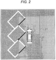
- FIG. 2 illustrates an overhead view in a case where the vehicle V is 0.5 m away from the parking frame end. It can be seen that it is not clear whether the end point of the parking frame line on the vehicle rear side, and the "intersection" where the end point of the parking frame line on the vehicle rear side and the parking frame line on the vehicle front side intersect at a right angle are recognizable in order to calculate the target parking position regardless of a situation that the vehicle approaches in such a short distance.
- FIG. 3 illustrates an overhead view in a case where the own vehicle V is 1.5 m away from the parking frame end in the parking lot of which the parking frame line is inclined by 60 deg.
- the parking frame line is recognized by a side camera from the viewpoint of recognition accuracy.
- the recognition range is almost the same as the display range of an HMI unit.
- the target parking position is determined on the basis of lines connecting the end point of the parking frame line on the rear side of the vehicle, a virtually extending line of the parking frame line on the front side of the vehicle, and the "intersection" intersecting at a right angle from the end point of the parking frame line on the vehicle rear side to a virtual line on the vehicle front side, and information is displayed on the HMI to indicate that parking is possible, so that the driver can recognize that the vehicle is able to be parked even in a region which is not displayed on the HMI. Therefore, the "target parking position" can be accurately determined without changing the camera tilt angle and the HMI display range, and can be notified to the driver, so that the usability can be improved.
- a parking support device of the invention includes an external field recognition unit which recognizes an external field, an information holding unit which holds information of a parking frame line recognized by the external field recognition unit, a parking region extraction unit which extracts a parking region from information of the parking frame line, a parking position determination unit which determines a target parking position from the parking region, and a path calculation unit which calculates a parking path from a current position of an own vehicle up to the target parking position.
- the target parking position is defined on the basis of lines connecting an end point of the parking frame line on a rear side of the own vehicle, a virtually extending line of the parking frame line on a front side of the own vehicle, and a point intersecting with the virtual line on a front side of the vehicle from the end point of the parking frame line on the rear side of the own vehicle.
- the external field recognition unit preferably recognizes the parking frame line using cameras which are attached at a leading end of the vehicle, a trailing end of the vehicle, or both side ends of the vehicle.
- the parking frame line preferably includes at least any one of a parallel line, a parking frame surrounded by lines, double parallel lines, a U-like frame line, an independent frame, and a T-like frame line.
- a center, an inner side, or an outer side of the frame line is preferably detected using the external field recognition unit.
- the parking region extraction unit preferably includes an inclined parking determination unit which determines whether the parking frame line is inclined with respect to a position of the own vehicle on the basis of the information of the parking frame line recognized by the external field recognition unit.
- an HMI unit which displays information on parking to a driver and receives information from the driver.
- the target parking position is preferably defined on the basis of lines connecting an end point of the parking frame line on a rear side of the own vehicle displayed in the HMI unit, a virtually extending line of the parking frame line on a front side of the own vehicle, and a point intersecting with the virtual line on the front side of the vehicle from the end point of the parking frame line on the rear side of the own vehicle.
- the HMI unit preferably displays information on the HMI unit to indicate that parking is possible.
- the HMI unit preferably determines whether the parking frame line is inclined with respect to a position of the own vehicle by the inclined parking determination unit.
- the HMI unit preferably displays information on the HMI unit to indicate that the parking is possible.
Landscapes
- Engineering & Computer Science (AREA)
- Physics & Mathematics (AREA)
- General Physics & Mathematics (AREA)
- Multimedia (AREA)
- Remote Sensing (AREA)
- Radar, Positioning & Navigation (AREA)
- Mechanical Engineering (AREA)
- Theoretical Computer Science (AREA)
- Computer Vision & Pattern Recognition (AREA)
- Automation & Control Theory (AREA)
- Geometry (AREA)
- Traffic Control Systems (AREA)
- Image Analysis (AREA)
Description
- The present invention relates to a vehicle control device which parks a vehicle at an arbitrary position according to a result of recognized external field, and particularly to a technology which can set a target parking position even in a case where only a part of a parking frame is recognizable due to a restriction such as a camera tilt angle or an HMI display range, and estimates the target parking position from visible recognition information.
- Conventionally, as a parking support device which supports a driving operation when a vehicle is parked, there is known a technique in which a space of the target parking position is detected to park an own vehicle using a distance measuring sensor for example, a frame image indicating the target parking position is drawn and displayed at a position corresponding to an image captured by a camera, and therefore, a driver can recognize the target parking position.
- In addition, regarding the problem that it is hard for the driver to determine whether the target parking position displayed on an HMI is the target parking position automatically detected on the basis of a recognition result, which causes anxiety in operation, there is known a technique in which different frame images are displayed depending on cases where the target parking position can be detected or where not, and therefore, the driver can check the display of the frame image so as to easily grasp whether the target parking position is appropriately detected.
- Specifically, in a case where the target parking position is detected, a detection procedure of the target parking position, that is, a frame image indicating a recommended target parking position in a plurality of target parking positions obtained by detection and other detected parking candidates are classified with colors and types of lines, and displayed at each position on an overhead image, so that the driver is informed of that the target parking position is detected.
- On the other hand, there is a technique in which, in a case where the target parking position is not able to be detected, a default frame image is displayed at a predetermined default position with respect to a position of the own vehicle, and therefore, instead of a parking frame line displayed on the HMI, a moving target parking position with respect to the own vehicle and a position adjustment icon of the default frame image on the image are displayed, so that the driver is informed of that the position is not able to be automatically detected. Furthermore, PTL 3 discloses a parking assistance apparatus which assist a driving operation of a driver at the time when the driver parks a vehicle during perpendicular parking.
-
- PTL 1:
JP 2011-39600 A - PTL 2:
JP 2013-35327 A - PTL 3:
EP 2 147 826 A2 - When a driver selects a desired parking position, the driver operates and selects the parking position on the HMI. Normally, it is necessary to recognize the parking frame with high accuracy by a side camera having a large tilt angle, and a recognition range is approximately a display range of the HMI.
- However, the techniques proposed in PTL 1 and PTL 2 are conceptual, and the range of the HMI and a camera recognition range are not clear.
- If a proposed range of the parking frame is recognized by the camera, the tilt angle of the camera is assumed to be large, and there is a possibility of causing a problem in the recognition accuracy. Particularly, most of the parking frame lines are not able to be recognized by the camera, or not be displayed on the HMI in an inclined parking mode.
- Therefore, in order to accurately recognize the parking frame line, it is necessary to reduce the tilt angle of the camera, but the recognition range is narrowed due to the reduction. Thus, a side camera is used for recognizing the parking frame normally, but the recognition range is approximately equal to the display range of the HMI in view of the recognition accuracy.
- Therefore, in the case of the tilt parking mode, it is necessary to approach the parking frame at a short distance due to restrictions on the camera recognition range and the display range of the HMI, and the driver may feel anxiety in a parking lot where the vehicle is parked.
- An object of the invention is to improve a usability by accurately determining a "target parking position" without changing a camera tilt angle and an HMI display range in a tilt parking mode, and notifying the driver of the information.
- In a parking support device of the invention to solve the above problem, an automatic parking system includes an external field recognition unit such as a camera and a sonar, which recognizes an external field, an information holding unit which holds information of a parking frame line recognized by the external field recognition unit, a parking region extraction unit which extracts a parking region from information of the parking frame line, a parking position determination unit which determines a target parking position from the parking region, and a path calculation unit which calculates a parking path from a current position of an own vehicle up to the target parking position. In a case where part of the parking frame line is not recognized by the camera, the target parking position is defined on the basis of lines connecting an end point of the parking frame line on a rear side of the own vehicle, a virtually extending line of the parking frame line on a front side of the own vehicle, and a point intersecting with the virtual line on a front side of the vehicle from the end point of the parking frame line on the rear side of the own vehicle.
- According to the invention, in an inclined parking mode, the target parking position can be determined on the basis of lines connecting the end point of the parking frame line on the rear side of the vehicle, a virtually extending line of the parking frame line on the front side of the vehicle, and the "intersection" intersecting at a right angle from the end point of the parking frame line on the vehicle rear side to a virtual line on the vehicle front side. Therefore, the "target parking position" can be accurately determined without changing a camera tilt angle and an HMI display range, and the usability can be improved by notifying the driver of the information.
- In addition, the invention can be mounted without changing a system, so that a versatility is increased and the cost is reduced.
- Other features of the invention will be clear from the description and the accompanying drawings. In addition, objects, configurations, and effects besides the above description will be apparent through the explanation on the following embodiments.
-
- [
FIG. 1] FIG. 1 is an overhead view in a case where a vehicle is 1.5 m away from a parking frame end in a parking lot in which a parking frame line is inclined by 45 deg. - [
FIG. 2] FIG. 2 is an overhead view in a case where the vehicle is 0.5 m away from the parking frame end in the parking lot where the parking frame line is inclined by 45 deg. - [
FIG. 3] FIG. 3 is an overhead view in a case where the vehicle is 1.5 m away from the parking frame end in the parking lot where the parking frame line is inclined by 60 deg. - [
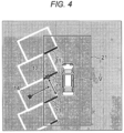
FIG. 4] FIG. 4 is an overhead view in a case where the vehicle is 0.5 m away from the parking frame end in the parking lot where the parking frame line is inclined by 60 deg. - [
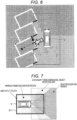
FIG. 5] FIG. 5 is a diagram illustrating an application example of the invention, and a method for determining a target parking position in a case where the vehicle is 1.5 m away from the parking frame end in the parking lot where the parking frame line is inclined by 45 deg. - [
FIG. 6] FIG. 6 is a diagram illustrating an application example of the invention, and a method for determining a target parking position in a case where the vehicle is 1.5 m away from the parking frame end in the parking lot where the parking frame line is inclined by 60 deg. - [
FIG. 7] FIG. 7 is a diagram illustrating a recognition range in a camera. - [
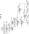
FIG. 8] FIG. 8 is a flowchart of control up to a tilt parking mode. - Hereinafter, embodiments of the invention will be described using the drawings.
- The invention is applied to a parking support system in which a target parking position is automatically detected to park an own vehicle, a frame image indicating the target parking position is drawn and overlapped on an overhead image around the own vehicle, so that a driver of the vehicle may recognize and select the automatically-detected target parking position.
- Then, particularly in the parking support system to which the invention is applied, a target parking position can be estimated from currently recognized information regardless of a situation that most parking frame line is not recognizable in a tilt parking mode. For example, in a case where it is possible to recognize an end point the parking frame line on a vehicle rear side and an "intersection" where the end point of the parking frame line on the vehicle rear side and the parking frame line on a vehicle front side intersect at a right angle, the target parking position can be calculated, and the notification to the driver can be performed without any problem. However, in a case where the "intersection" is not recognizable, the target parking position can be determined on the basis of lines connecting the end point of the parking frame line on the vehicle rear side, a line virtually extending from the parking frame line on the vehicle front side, and an "intersection" intersecting at a right angle from the end point of the parking frame line on the vehicle rear side to a virtual line on the vehicle front side.
- In the following, the description will be given using an overhead view in a case where the vehicle is away from a parking frame end by a certain distance in a parking lot of which the parking frame line is inclined.
- An overhead view in the parking support system is illustrated in
FIG. 1 . - In the overhead view, a vehicle V is 1.5 m away from the parking frame end in a parking lot of which the parking frame line is inclined by 45 deg. The parking frame line is recognized by a side camera from the viewpoint of recognition accuracy. The recognition range is almost the same as a
display range 11 of an HMI unit. A distance of 1.5 m from the parking frame end is a boundary distance at which the driver feels anxiety. However, in a parking lot of the inclined parking, it can be seen that most parking frame line is not recognizable. However, in order to calculate the target parking position, there is a need to recognize the end point of the parking frame line on the vehicle rear side, and an "intersection" at which the end point of the parking frame line on the vehicle rear side and the parking frame line on the vehicle front side intersect at a right angle. Therefore, most automatic parking systems are not able to cope with the inclined parking. - Similarly,
FIG. 2 illustrates an overhead view in a case where the vehicle V is 0.5 m away from the parking frame end. It can be seen that it is not clear whether the end point of the parking frame line on the vehicle rear side, and the "intersection" where the end point of the parking frame line on the vehicle rear side and the parking frame line on the vehicle front side intersect at a right angle are recognizable in order to calculate the target parking position regardless of a situation that the vehicle approaches in such a short distance. - Next,
FIG. 3 illustrates an overhead view in a case where the own vehicle V is 1.5 m away from the parking frame end in the parking lot of which the parking frame line is inclined by 60 deg. The parking frame line is recognized by a side camera from the viewpoint of recognition accuracy. The recognition range is almost the same as the display range of an HMI unit. Herein, it can also be seen that it is not clear whether the end point of the parking frame line on the vehicle rear side, and the "intersection" where the end point of the parking frame line on the vehicle rear side and the parking frame line on the vehicle front side intersect at a right angle are recognizable in order to calculate the target parking position. - On the other hand, in a case where the vehicle V is 0.5 m away from the parking frame end in the parking lot of which the parking frame line is inclined by 60 deg, it is possible to securely recognize the "intersection" where the end point of the parking frame line on the vehicle rear side and the "intersection" where the end point of the parking frame line on the vehicle rear side and the parking frame line on the vehicle front side intersect at a right angle as illustrated in
FIG. 4 . Therefore it is possible to set the target parking position. However, in an actual environment, there are other vehicles in the parking frames, and approaching up to 0.5 m may cause anxiety. - In other words, in the tile parking mode, there is a need to increase a coverage in an actual environment. One of corresponding techniques is to expand a recognition region of the camera. However, a camera performance UP, a camera tilt angle resetting, and a recognition logic redesigning come into request, and make the cost increase. In addition, as another method, the expansion of the HMI display range is exemplified. This method seems to be optimized at a glance, but the recognition information is complicated, causing the relation with a position of the own vehicle to be hardly understood. In addition, a display object becomes small, and is hardly recognized by the driver. Therefore, there is a need of a device to accurately determine the "target parking position" without changing the camera tilt angle and the HMI display range.
- Thus, in an environment that the parking frame line is almost not able to be recognized in an inclined parking mode, the target parking position is determined on the basis of lines connecting the end point of the parking frame line on the rear side of the vehicle, a virtually extending line of the parking frame line on the front side of the vehicle, and the "intersection" intersecting at a right angle from the end point of the parking frame line on the vehicle rear side to a virtual line on the vehicle front side, and information is displayed on the HMI to indicate that parking is possible, so that the driver can recognize that the vehicle is able to be parked even in a region which is not displayed on the HMI. Therefore, the "target parking position" can be accurately determined without changing the camera tilt angle and the HMI display range, and can be notified to the driver, so that the usability can be improved.
- A parking support device of the invention includes an external field recognition unit which recognizes an external field, an information holding unit which holds information of a parking frame line recognized by the external field recognition unit, a parking region extraction unit which extracts a parking region from information of the parking frame line, a parking position determination unit which determines a target parking position from the parking region, and a path calculation unit which calculates a parking path from a current position of an own vehicle up to the target parking position. In a case where part of the parking frame line is not recognized by the external field recognition unit, the target parking position is defined on the basis of lines connecting an end point of the parking frame line on a rear side of the own vehicle, a virtually extending line of the parking frame line on a front side of the own vehicle, and a point intersecting with the virtual line on a front side of the vehicle from the end point of the parking frame line on the rear side of the own vehicle.
- Then, the external field recognition unit preferably recognizes the parking frame line using cameras which are attached at a leading end of the vehicle, a trailing end of the vehicle, or both side ends of the vehicle.
- In addition, the parking frame line preferably includes at least any one of a parallel line, a parking frame surrounded by lines, double parallel lines, a U-like frame line, an independent frame, and a T-like frame line. A center, an inner side, or an outer side of the frame line is preferably detected using the external field recognition unit.
- The parking region extraction unit preferably includes an inclined parking determination unit which determines whether the parking frame line is inclined with respect to a position of the own vehicle on the basis of the information of the parking frame line recognized by the external field recognition unit.
- There is provided an HMI unit which displays information on parking to a driver and receives information from the driver. In a case where part of the parking frame line is out of a display range of the HMI unit, the target parking position is preferably defined on the basis of lines connecting an end point of the parking frame line on a rear side of the own vehicle displayed in the HMI unit, a virtually extending line of the parking frame line on a front side of the own vehicle, and a point intersecting with the virtual line on the front side of the vehicle from the end point of the parking frame line on the rear side of the own vehicle.
- In a case where part of the parking frame line is out of the display range of the HMI unit and it is determined that the target parking position is able to be defined on the basis of lines connecting the end point of the parking frame line on the rear side of the own vehicle displayed in the HMI, the virtually expending line of the parking frame line on the front side of the own vehicle, and the point intersecting with the virtual line on the front side of the vehicle from the end point of the parking frame line on the rear side of the own vehicle, the HMI unit preferably displays information on the HMI unit to indicate that parking is possible.
- In a case where part of the parking frame line is out of the display range of the HMI unit, and the parking frame line on the rear side of the own vehicle displayed in the HMI unit and the parking frame line on the front side of the own vehicle are recognized, the HMI unit preferably determines whether the parking frame line is inclined with respect to a position of the own vehicle by the inclined parking determination unit.
- In a case where it is determined that the parking frame line is inclined with respect to the position of the own vehicle, the HMI unit preferably displays information on the HMI unit to indicate that the parking is possible.
Claims (7)
- A parking support device, comprising:an external field recognition unit which is configured to recognize a parking frame line using a plurality of cameras which are attached at a leading end of the vehicle, a trailing end of the vehicle, or both side ends of the vehicle;an information holding unit which is configured to hold information of the parking frame line recognized by the external field recognition unit;a parking region extraction unit which is configured to extract a parking region from information of the parking frame line;a parking position determination unit which is configured to determine a target parking position from the parking region; anda path calculation unit which is configured to calculate a parking path from a current position of an own vehicle (V) up to the target parking position,wherein, in a case where part of the parking frame line is not recognized by the external field recognition unit, the target parking position is defined on the basis of lines connecting an end point of the parking frame line on a rear side of the own vehicle, a virtually extending line of the parking frame line on a front side of the own vehicle, and a point intersecting with the virtual line on a front side of the vehicle (V) from the end point of the parking frame line on the rear side of the own vehicle.
- The parking support device according to claim 1,wherein the parking frame line includes at least any one of a parallel line, a parking frame surrounded by lines, double parallel lines, a U-like frame line, an independent frame, and a T-like frame line, andwherein a center, an inner side, or an outer side of the frame line is detected using the external field recognition unit.
- The parking support device according to claim 1,
wherein the parking region extraction unit includes an inclined parking determination unit which determines whether the parking frame line is inclined with respect to a position of the own vehicle (V) on the basis of the information of the parking frame line recognized by the external field recognition unit. - The parking support device according to claim 1, further comprising:an HMI unit which is configured to display information on parking to a driver and receives information from the driver,wherein, in a case where part of the parking frame line is out of a display range (11) of the HMI unit, the target parking position is defined on the basis of lines connecting an end point of the parking frame line on a rear side of the own vehicle (V) displayed in the HMI unit, a virtually extending line of the parking frame line on a front side of the own vehicle, and a point intersecting with the virtual line on the front side of the vehicle (V) from the end point of the parking frame line on the rear side of the own vehicle.
- The parking support device according to claim 4,
wherein, in a case where part of the parking frame line is out of the display range (11) of the HMI unit and it is determined that the target parking position is able to be defined on the basis of lines connecting the end point of the parking frame line on the rear side of the own vehicle (V) displayed in the HMI, the virtually expending line of the parking frame line on the front side of the own vehicle, and the point intersecting with the virtual line on the front side of the vehicle (V) from the end point of the parking frame line on the rear side of the own vehicle, the HMI unit displays information on the HMI unit to indicate that parking is possible. - The parking support device according to claim 4,
wherein, in a case where part of the parking frame line is out of the display range (11) of the HMI unit, and the parking frame line on the rear side of the own vehicle (V) displayed in the HMI unit and the parking frame line on the front side of the own vehicle (V) are recognized, the HMI unit determines whether the parking frame line is inclined with respect to a position of the own vehicle (V) by the inclined parking determination unit. - The parking support device according to claim 6,
wherein, in a case where it is determined that the parking frame line is inclined with respect to the position of the own vehicle, the HMI unit displays information on the HMI unit to indicate that the parking is possible.
Applications Claiming Priority (2)
| Application Number | Priority Date | Filing Date | Title |
|---|---|---|---|
| JP2017191877 | 2017-09-29 | ||
| PCT/JP2018/028794 WO2019064907A1 (en) | 2017-09-29 | 2018-08-01 | Parking assistance device |
Publications (3)
| Publication Number | Publication Date |
|---|---|
| EP3690813A1 EP3690813A1 (en) | 2020-08-05 |
| EP3690813A4 EP3690813A4 (en) | 2021-07-14 |
| EP3690813B1 true EP3690813B1 (en) | 2025-04-30 |
Family
ID=65902362
Family Applications (1)
| Application Number | Title | Priority Date | Filing Date |
|---|---|---|---|
| EP18861970.4A Active EP3690813B1 (en) | 2017-09-29 | 2018-08-01 | Parking assistance device |
Country Status (5)
| Country | Link |
|---|---|
| US (1) | US11535152B2 (en) |
| EP (1) | EP3690813B1 (en) |
| JP (1) | JP6924269B2 (en) |
| CN (1) | CN111108503B (en) |
| WO (1) | WO2019064907A1 (en) |
Families Citing this family (5)
| Publication number | Priority date | Publication date | Assignee | Title |
|---|---|---|---|---|
| JP7296768B2 (en) * | 2019-04-22 | 2023-06-23 | フォルシアクラリオン・エレクトロニクス株式会社 | Image processing device and image processing method |
| JP6975766B2 (en) * | 2019-12-13 | 2021-12-01 | 本田技研工業株式会社 | Parking support device, parking support method and program |
| KR102473407B1 (en) * | 2020-12-28 | 2022-12-05 | 삼성전기주식회사 | Vehicle's svm system using tilt camera |
| CN113830076B (en) * | 2021-09-17 | 2023-12-19 | 东风柳州汽车有限公司 | Parking method, device, equipment and storage medium |
| CN114771506A (en) * | 2022-05-07 | 2022-07-22 | 浙江吉利控股集团有限公司 | Parking track determination method, device, equipment and storage medium |
Family Cites Families (8)
| Publication number | Priority date | Publication date | Assignee | Title |
|---|---|---|---|---|
| JP5182545B2 (en) * | 2007-05-16 | 2013-04-17 | アイシン精機株式会社 | Parking assistance device |
| JP4661917B2 (en) * | 2008-07-25 | 2011-03-30 | 日産自動車株式会社 | Parking assistance device and parking assistance method |
| JP5471141B2 (en) | 2009-08-06 | 2014-04-16 | 日産自動車株式会社 | Parking assistance device and parking assistance method |
| JP5982750B2 (en) * | 2011-08-04 | 2016-08-31 | 日産自動車株式会社 | Parking assistance device and parking assistance method |
| US9378425B2 (en) | 2012-11-27 | 2016-06-28 | Clarion Co., Ltd. | On-vehicle image processing device |
| JP6097533B2 (en) * | 2012-11-27 | 2017-03-15 | クラリオン株式会社 | In-vehicle image processing device |
| JP6313081B2 (en) * | 2014-03-20 | 2018-04-18 | クラリオン株式会社 | In-vehicle image processing apparatus and vehicle system using the same |
| RU2691498C1 (en) * | 2015-10-22 | 2019-06-14 | Ниссан Мотор Ко., Лтд. | Method (versions) and parking places lines detection device |
-
2018
- 2018-08-01 US US16/641,726 patent/US11535152B2/en active Active
- 2018-08-01 CN CN201880047758.7A patent/CN111108503B/en active Active
- 2018-08-01 JP JP2019544361A patent/JP6924269B2/en active Active
- 2018-08-01 WO PCT/JP2018/028794 patent/WO2019064907A1/en not_active Ceased
- 2018-08-01 EP EP18861970.4A patent/EP3690813B1/en active Active
Also Published As
| Publication number | Publication date |
|---|---|
| EP3690813A4 (en) | 2021-07-14 |
| WO2019064907A1 (en) | 2019-04-04 |
| US11535152B2 (en) | 2022-12-27 |
| JPWO2019064907A1 (en) | 2020-11-19 |
| CN111108503A (en) | 2020-05-05 |
| CN111108503B (en) | 2023-08-08 |
| JP6924269B2 (en) | 2021-08-25 |
| US20200353866A1 (en) | 2020-11-12 |
| EP3690813A1 (en) | 2020-08-05 |
Similar Documents
| Publication | Publication Date | Title |
|---|---|---|
| US11535152B2 (en) | Parking support device | |
| US10710502B2 (en) | In-vehicle alert apparatus and alert method | |
| EP3650285B1 (en) | Parking assistance method and parking assistance device | |
| EP2080668B1 (en) | Driving assist device, method and computer program product for a vehicle | |
| EP2819858B1 (en) | Hitch alignment assistance | |
| EP3650315B1 (en) | Parking assistance method and parking assistance device | |
| KR102181196B1 (en) | Parking control method and parking control device | |
| US9919703B2 (en) | Method and device for assisting a maneuvering process of a motor vehicle | |
| US9697735B2 (en) | Drive assistance device | |
| JP6614359B2 (en) | Obstacle determination method, parking support method, exit support method, and obstacle determination device | |
| KR20150012799A (en) | Apparatus and method for providing parking control | |
| US20180174464A1 (en) | Driving assistance apparatus | |
| EP3196076A1 (en) | Electronic mirror device | |
| EP3731138B1 (en) | Image processing device and image processing method | |
| JP6325365B2 (en) | Steering support control device | |
| JP2018077566A (en) | Attitude estimation method for parking control apparatus and attitude estimation apparatus | |
| KR20210057897A (en) | Apparatus for controlling safety driving of vehicle and method thereof | |
| US20210209383A1 (en) | Vehicle control device and vehicle control method | |
| JP2006182108A (en) | Vehicle periphery monitoring device | |
| JP2000289548A (en) | Vehicle backing support device | |
| JP2005189936A (en) | Vehicle control system | |
| JP4400264B2 (en) | Moving object danger judgment device | |
| JP2011148424A (en) | Vehicle guiding device | |
| US20190072658A1 (en) | Device and Method for Determining the Initial Direction of Movement of an Object in the Detection Range of a Motor Vehicle Radar Sensor |
Legal Events
| Date | Code | Title | Description |
|---|---|---|---|
| STAA | Information on the status of an ep patent application or granted ep patent |
Free format text: STATUS: THE INTERNATIONAL PUBLICATION HAS BEEN MADE |
|
| PUAI | Public reference made under article 153(3) epc to a published international application that has entered the european phase |
Free format text: ORIGINAL CODE: 0009012 |
|
| STAA | Information on the status of an ep patent application or granted ep patent |
Free format text: STATUS: REQUEST FOR EXAMINATION WAS MADE |
|
| 17P | Request for examination filed |
Effective date: 20200429 |
|
| AK | Designated contracting states |
Kind code of ref document: A1 Designated state(s): AL AT BE BG CH CY CZ DE DK EE ES FI FR GB GR HR HU IE IS IT LI LT LU LV MC MK MT NL NO PL PT RO RS SE SI SK SM TR |
|
| AX | Request for extension of the european patent |
Extension state: BA ME |
|
| DAV | Request for validation of the european patent (deleted) | ||
| DAX | Request for extension of the european patent (deleted) | ||
| A4 | Supplementary search report drawn up and despatched |
Effective date: 20210611 |
|
| RIC1 | Information provided on ipc code assigned before grant |
Ipc: G08G 1/16 20060101ALI20210607BHEP Ipc: G06T 7/00 20170101ALI20210607BHEP Ipc: B60R 99/00 20090101ALI20210607BHEP Ipc: G06T 7/60 20170101ALI20210607BHEP Ipc: G06K 9/00 20060101AFI20210607BHEP |
|
| RAP3 | Party data changed (applicant data changed or rights of an application transferred) |
Owner name: HITACHI ASTEMO, LTD. |
|
| GRAP | Despatch of communication of intention to grant a patent |
Free format text: ORIGINAL CODE: EPIDOSNIGR1 |
|
| STAA | Information on the status of an ep patent application or granted ep patent |
Free format text: STATUS: GRANT OF PATENT IS INTENDED |
|
| RIC1 | Information provided on ipc code assigned before grant |
Ipc: B60R 99/00 20090101ALI20241113BHEP Ipc: G06T 7/00 20170101ALI20241113BHEP Ipc: G08G 1/16 20060101ALI20241113BHEP Ipc: G06T 7/60 20170101AFI20241113BHEP |
|
| INTG | Intention to grant announced |
Effective date: 20241126 |
|
| RIN1 | Information on inventor provided before grant (corrected) |
Inventor name: TAKAHASHI KOJI Inventor name: OKUBO SATORU |
|
| GRAS | Grant fee paid |
Free format text: ORIGINAL CODE: EPIDOSNIGR3 |
|
| GRAA | (expected) grant |
Free format text: ORIGINAL CODE: 0009210 |
|
| STAA | Information on the status of an ep patent application or granted ep patent |
Free format text: STATUS: THE PATENT HAS BEEN GRANTED |
|
| AK | Designated contracting states |
Kind code of ref document: B1 Designated state(s): AL AT BE BG CH CY CZ DE DK EE ES FI FR GB GR HR HU IE IS IT LI LT LU LV MC MK MT NL NO PL PT RO RS SE SI SK SM TR |
|
| REG | Reference to a national code |
Ref country code: CH Ref legal event code: EP Ref country code: GB Ref legal event code: FG4D |
|
| REG | Reference to a national code |
Ref country code: IE Ref legal event code: FG4D |
|
| REG | Reference to a national code |
Ref country code: DE Ref legal event code: R096 Ref document number: 602018081605 Country of ref document: DE |
|
| REG | Reference to a national code |
Ref country code: NL Ref legal event code: MP Effective date: 20250430 |
|
| REG | Reference to a national code |
Ref country code: AT Ref legal event code: MK05 Ref document number: 1790775 Country of ref document: AT Kind code of ref document: T Effective date: 20250430 |
|
| PG25 | Lapsed in a contracting state [announced via postgrant information from national office to epo] |
Ref country code: PT Free format text: LAPSE BECAUSE OF FAILURE TO SUBMIT A TRANSLATION OF THE DESCRIPTION OR TO PAY THE FEE WITHIN THE PRESCRIBED TIME-LIMIT Effective date: 20250901 Ref country code: ES Free format text: LAPSE BECAUSE OF FAILURE TO SUBMIT A TRANSLATION OF THE DESCRIPTION OR TO PAY THE FEE WITHIN THE PRESCRIBED TIME-LIMIT Effective date: 20250430 Ref country code: FI Free format text: LAPSE BECAUSE OF FAILURE TO SUBMIT A TRANSLATION OF THE DESCRIPTION OR TO PAY THE FEE WITHIN THE PRESCRIBED TIME-LIMIT Effective date: 20250430 |
|
| PGFP | Annual fee paid to national office [announced via postgrant information from national office to epo] |
Ref country code: DE Payment date: 20250831 Year of fee payment: 8 |
|
| REG | Reference to a national code |
Ref country code: LT Ref legal event code: MG9D |
|
| PG25 | Lapsed in a contracting state [announced via postgrant information from national office to epo] |
Ref country code: GR Free format text: LAPSE BECAUSE OF FAILURE TO SUBMIT A TRANSLATION OF THE DESCRIPTION OR TO PAY THE FEE WITHIN THE PRESCRIBED TIME-LIMIT Effective date: 20250731 Ref country code: NO Free format text: LAPSE BECAUSE OF FAILURE TO SUBMIT A TRANSLATION OF THE DESCRIPTION OR TO PAY THE FEE WITHIN THE PRESCRIBED TIME-LIMIT Effective date: 20250730 |
|
| PG25 | Lapsed in a contracting state [announced via postgrant information from national office to epo] |
Ref country code: PL Free format text: LAPSE BECAUSE OF FAILURE TO SUBMIT A TRANSLATION OF THE DESCRIPTION OR TO PAY THE FEE WITHIN THE PRESCRIBED TIME-LIMIT Effective date: 20250430 Ref country code: NL Free format text: LAPSE BECAUSE OF FAILURE TO SUBMIT A TRANSLATION OF THE DESCRIPTION OR TO PAY THE FEE WITHIN THE PRESCRIBED TIME-LIMIT Effective date: 20250430 |
|
| PG25 | Lapsed in a contracting state [announced via postgrant information from national office to epo] |
Ref country code: BG Free format text: LAPSE BECAUSE OF FAILURE TO SUBMIT A TRANSLATION OF THE DESCRIPTION OR TO PAY THE FEE WITHIN THE PRESCRIBED TIME-LIMIT Effective date: 20250430 |
|
| PG25 | Lapsed in a contracting state [announced via postgrant information from national office to epo] |
Ref country code: HR Free format text: LAPSE BECAUSE OF FAILURE TO SUBMIT A TRANSLATION OF THE DESCRIPTION OR TO PAY THE FEE WITHIN THE PRESCRIBED TIME-LIMIT Effective date: 20250430 |
|
| PG25 | Lapsed in a contracting state [announced via postgrant information from national office to epo] |
Ref country code: AT Free format text: LAPSE BECAUSE OF FAILURE TO SUBMIT A TRANSLATION OF THE DESCRIPTION OR TO PAY THE FEE WITHIN THE PRESCRIBED TIME-LIMIT Effective date: 20250430 |
|
| PG25 | Lapsed in a contracting state [announced via postgrant information from national office to epo] |
Ref country code: RS Free format text: LAPSE BECAUSE OF FAILURE TO SUBMIT A TRANSLATION OF THE DESCRIPTION OR TO PAY THE FEE WITHIN THE PRESCRIBED TIME-LIMIT Effective date: 20250731 |
|
| PG25 | Lapsed in a contracting state [announced via postgrant information from national office to epo] |
Ref country code: IS Free format text: LAPSE BECAUSE OF FAILURE TO SUBMIT A TRANSLATION OF THE DESCRIPTION OR TO PAY THE FEE WITHIN THE PRESCRIBED TIME-LIMIT Effective date: 20250830 |
|
| PG25 | Lapsed in a contracting state [announced via postgrant information from national office to epo] |
Ref country code: LV Free format text: LAPSE BECAUSE OF FAILURE TO SUBMIT A TRANSLATION OF THE DESCRIPTION OR TO PAY THE FEE WITHIN THE PRESCRIBED TIME-LIMIT Effective date: 20250430 |
|
| PG25 | Lapsed in a contracting state [announced via postgrant information from national office to epo] |
Ref country code: SM Free format text: LAPSE BECAUSE OF FAILURE TO SUBMIT A TRANSLATION OF THE DESCRIPTION OR TO PAY THE FEE WITHIN THE PRESCRIBED TIME-LIMIT Effective date: 20250430 Ref country code: DK Free format text: LAPSE BECAUSE OF FAILURE TO SUBMIT A TRANSLATION OF THE DESCRIPTION OR TO PAY THE FEE WITHIN THE PRESCRIBED TIME-LIMIT Effective date: 20250430 |
|
| PG25 | Lapsed in a contracting state [announced via postgrant information from national office to epo] |
Ref country code: CZ Free format text: LAPSE BECAUSE OF FAILURE TO SUBMIT A TRANSLATION OF THE DESCRIPTION OR TO PAY THE FEE WITHIN THE PRESCRIBED TIME-LIMIT Effective date: 20250430 |
|
| PG25 | Lapsed in a contracting state [announced via postgrant information from national office to epo] |
Ref country code: EE Free format text: LAPSE BECAUSE OF FAILURE TO SUBMIT A TRANSLATION OF THE DESCRIPTION OR TO PAY THE FEE WITHIN THE PRESCRIBED TIME-LIMIT Effective date: 20250430 |
|
| PG25 | Lapsed in a contracting state [announced via postgrant information from national office to epo] |
Ref country code: SK Free format text: LAPSE BECAUSE OF FAILURE TO SUBMIT A TRANSLATION OF THE DESCRIPTION OR TO PAY THE FEE WITHIN THE PRESCRIBED TIME-LIMIT Effective date: 20250430 Ref country code: RO Free format text: LAPSE BECAUSE OF FAILURE TO SUBMIT A TRANSLATION OF THE DESCRIPTION OR TO PAY THE FEE WITHIN THE PRESCRIBED TIME-LIMIT Effective date: 20250430 |
|
| PG25 | Lapsed in a contracting state [announced via postgrant information from national office to epo] |
Ref country code: IT Free format text: LAPSE BECAUSE OF FAILURE TO SUBMIT A TRANSLATION OF THE DESCRIPTION OR TO PAY THE FEE WITHIN THE PRESCRIBED TIME-LIMIT Effective date: 20250430 |
|
| REG | Reference to a national code |
Ref country code: DE Ref legal event code: R097 Ref document number: 602018081605 Country of ref document: DE |
|
| PLBE | No opposition filed within time limit |
Free format text: ORIGINAL CODE: 0009261 |
|
| STAA | Information on the status of an ep patent application or granted ep patent |
Free format text: STATUS: NO OPPOSITION FILED WITHIN TIME LIMIT |
|
| REG | Reference to a national code |
Ref country code: CH Ref legal event code: L10 Free format text: ST27 STATUS EVENT CODE: U-0-0-L10-L00 (AS PROVIDED BY THE NATIONAL OFFICE) Effective date: 20260311 |
|
| REG | Reference to a national code |
Ref country code: CH Ref legal event code: H13 Free format text: ST27 STATUS EVENT CODE: U-0-0-H10-H13 (AS PROVIDED BY THE NATIONAL OFFICE) Effective date: 20260324 |
|
| PG25 | Lapsed in a contracting state [announced via postgrant information from national office to epo] |
Ref country code: MC Free format text: LAPSE BECAUSE OF FAILURE TO SUBMIT A TRANSLATION OF THE DESCRIPTION OR TO PAY THE FEE WITHIN THE PRESCRIBED TIME-LIMIT Effective date: 20250430 |
|
| 26N | No opposition filed |
Effective date: 20260202 |
|
| PG25 | Lapsed in a contracting state [announced via postgrant information from national office to epo] |
Ref country code: LU Free format text: LAPSE BECAUSE OF NON-PAYMENT OF DUE FEES Effective date: 20250801 |
|
| PG25 | Lapsed in a contracting state [announced via postgrant information from national office to epo] |
Ref country code: CH Free format text: LAPSE BECAUSE OF NON-PAYMENT OF DUE FEES Effective date: 20250831 |
|
| GBPC | Gb: european patent ceased through non-payment of renewal fee |
Effective date: 20250801 |