EP3690760A1 - Device and method to improve the robustness against "adversarial examples" - Google Patents
Device and method to improve the robustness against "adversarial examples" Download PDFInfo
- Publication number
- EP3690760A1 EP3690760A1 EP19155345.2A EP19155345A EP3690760A1 EP 3690760 A1 EP3690760 A1 EP 3690760A1 EP 19155345 A EP19155345 A EP 19155345A EP 3690760 A1 EP3690760 A1 EP 3690760A1
- Authority
- EP
- European Patent Office
- Prior art keywords
- value
- classifier
- input signal
- class
- robustness
- Prior art date
- Legal status (The legal status is an assumption and is not a legal conclusion. Google has not performed a legal analysis and makes no representation as to the accuracy of the status listed.)
- Granted
Links
Images







Classifications
-
- G—PHYSICS
- G06—COMPUTING OR CALCULATING; COUNTING
- G06N—COMPUTING ARRANGEMENTS BASED ON SPECIFIC COMPUTATIONAL MODELS
- G06N20/00—Machine learning
-
- G—PHYSICS
- G06—COMPUTING OR CALCULATING; COUNTING
- G06F—ELECTRIC DIGITAL DATA PROCESSING
- G06F18/00—Pattern recognition
- G06F18/20—Analysing
- G06F18/21—Design or setup of recognition systems or techniques; Extraction of features in feature space; Blind source separation
- G06F18/217—Validation; Performance evaluation; Active pattern learning techniques
- G06F18/2193—Validation; Performance evaluation; Active pattern learning techniques based on specific statistical tests
-
- G—PHYSICS
- G06—COMPUTING OR CALCULATING; COUNTING
- G06F—ELECTRIC DIGITAL DATA PROCESSING
- G06F18/00—Pattern recognition
- G06F18/20—Analysing
- G06F18/24—Classification techniques
- G06F18/241—Classification techniques relating to the classification model, e.g. parametric or non-parametric approaches
- G06F18/2415—Classification techniques relating to the classification model, e.g. parametric or non-parametric approaches based on parametric or probabilistic models, e.g. based on likelihood ratio or false acceptance rate versus a false rejection rate
-
- G—PHYSICS
- G06—COMPUTING OR CALCULATING; COUNTING
- G06F—ELECTRIC DIGITAL DATA PROCESSING
- G06F18/00—Pattern recognition
- G06F18/20—Analysing
- G06F18/24—Classification techniques
- G06F18/243—Classification techniques relating to the number of classes
- G06F18/2431—Multiple classes
-
- G—PHYSICS
- G06—COMPUTING OR CALCULATING; COUNTING
- G06N—COMPUTING ARRANGEMENTS BASED ON SPECIFIC COMPUTATIONAL MODELS
- G06N7/00—Computing arrangements based on specific mathematical models
- G06N7/01—Probabilistic graphical models, e.g. probabilistic networks
-
- G—PHYSICS
- G06—COMPUTING OR CALCULATING; COUNTING
- G06V—IMAGE OR VIDEO RECOGNITION OR UNDERSTANDING
- G06V10/00—Arrangements for image or video recognition or understanding
- G06V10/70—Arrangements for image or video recognition or understanding using pattern recognition or machine learning
- G06V10/77—Processing image or video features in feature spaces; using data integration or data reduction, e.g. principal component analysis [PCA] or independent component analysis [ICA] or self-organising maps [SOM]; Blind source separation
- G06V10/774—Generating sets of training patterns; Bootstrap methods, e.g. bagging or boosting
-
- G—PHYSICS
- G06—COMPUTING OR CALCULATING; COUNTING
- G06V—IMAGE OR VIDEO RECOGNITION OR UNDERSTANDING
- G06V10/00—Arrangements for image or video recognition or understanding
- G06V10/70—Arrangements for image or video recognition or understanding using pattern recognition or machine learning
- G06V10/77—Processing image or video features in feature spaces; using data integration or data reduction, e.g. principal component analysis [PCA] or independent component analysis [ICA] or self-organising maps [SOM]; Blind source separation
- G06V10/776—Validation; Performance evaluation
-
- G—PHYSICS
- G06—COMPUTING OR CALCULATING; COUNTING
- G06V—IMAGE OR VIDEO RECOGNITION OR UNDERSTANDING
- G06V10/00—Arrangements for image or video recognition or understanding
- G06V10/70—Arrangements for image or video recognition or understanding using pattern recognition or machine learning
- G06V10/82—Arrangements for image or video recognition or understanding using pattern recognition or machine learning using neural networks
Definitions
- the invention concerns a method for assessing a robustness of a smoothed classifier, a method for assessing an overall robustness of a smoothed classifier, a method for training a smoothed classifier, a method for operating a smoothed classifier, a method for providing an actuator control signal, a computer program and a machine-readable storage medium.
- classifiers like e.g. neural network classification systems can easily be fooled. It is well known that classifiers which may be based on deep learning may be sensitive to small perturbations. In order to deploy such systems in the physical world it is important to provide a proof about the system's robustness.
- a smoothed classifier g may be defined as follows: When presented with an input x , the smoothed classifier g returns the most likely prediction by base classifier f under noise, in particular under random Gaussian perturbations of input signal x : where ⁇ (0, ⁇ 2 I ) for some predefined variance ⁇ 2 .
- the method with the features of independent claim 1 yields a robustness value (also called a robustness bound ) that guarantees that the classification yielded by smoothed classifier g is the same for all input vectors that lie within a ball of radius around input signal x.
- the invention is concerned with a computer-implemented method for assessing a robustness of a smoothed classifier ( g ) for classifying sensor signals received from a sensor (30), comprising the steps of:
- the smoothed classifier ( g ) is robust if and only if said robustness value is larger than a predefined threshold.
- said predefined threshold may be given by a quantity characterizing noise in said sensor signals.
- said robustness value is determined proportional to ⁇ -1 ( p A ) - ⁇ -1 ( p B ), preferably ⁇ ⁇ ( ⁇ -1 ( p A ) - ⁇ -1 ( p B )).
- test set comprising a plurality of test input signals ( x i ).
- test input signal ( x i ) as input signal (x) as above, it is then possible to determine a plurality of test robustness values ( ), each corresponding to one of the test input signals ( x i ). It is then possible to determine an overall robustrness value ( ) that characterizes the determined set of test robustness values ( ), for example its minimum value.
- the smoothed classifier (g) is robust if and only if said overall robustness value is larger than a predefined threshold.
- said smoothed classifier ( g ) is robust or not based on a relative size of said robustness value ( ) and said overall robustness value ( ).
- Said relative size is an indicator whether said input signal (x) is meaningfully represented by the test set, or not, or, in other words, whether said input signal (x) is representative of said test set.
- said smoothed classifier ( g ) is robust if and only if said relative size, for example a quotient / R ov R , is larger than a second predefined threshold.
- this decision whether the smoothed classifier ( g ) is robust or not as a cut-off criterion for training of said smoothed classifier ( g ), wherein training is continued if said smooth classifier ( g ) is determined to be non-robust.
- relative size for training during operation of said smoothed classifier. It may be envisioned to operate said smoothed classifier ( g ), determining whether said smoothed classifier ( g ) is robust or not using the above method, and, if said smoothed classifier ( g ) is determined to be non-robust based on said relative size, send said input signal (x) to a remote server, receive, from said remote server, a target classification of said input signal (x), and further train said smoothed classifier ( g ) using said input signal (x) and said target classification.
- said target classification may have been provided by a human expert.
- Remote may mean that said remote server and a computer executing said smoothed classifier are not integrated in a single unit.
- said robustness value as a trigger for closer inspection, by determining, using the above method, said robustness value ( ) of said smoothed classifier ( g ) when provided with said input signal (x) and adjusting operating parameters of said sensor (30) depending on said robustness value.
- said sensor (30) may be controlled to zoom into a region that is classified as non-robust.
- said robustness value for safe operation of an actuator by assessing whether said smoothed classifier ( g ) is robust or not using the above method, and determining an actuator control signal (A) for controlling said actuator in accordance with a result of said assessment, in particular by determining said actuator control signal (A) to cause said actuator to operate in a safe mode if said smoothed classifier ( g ) is deemed not robust as a result of said assessment.
- the above methods are not limited in application to automated driving. In other applications, it may be envisioned to have said actuator controlling an at least partially autonomous robot (100) and/or a manufacturing machine (200)) and/or an access control system (300).
- FIG. 1 Shown in figure 1 is one embodiment of an actuator 10 in its environment 20.
- Actuator 10 interacts with a control system 40.
- Actuator 10 and its environment 20 will be jointly called actuator system.
- a sensor 30 senses a condition of the actuator system.
- the sensor 30 may comprise several sensors.
- sensor 30 is an optical sensor that takes images of the environment 20.
- An output signal S of sensor 30 (or, in case the sensor 30 comprises a plurality of sensors, an output signal S for each of the sensors) which encodes the sensed condition is transmitted to the control system 40.
- control system 40 receives a stream of sensor signals S. It then computes a series of actuator control commands A depending on the stream of sensor signals S, which are then transmitted to actuator 10.
- Control system 40 receives the stream of sensor signals S of sensor 30 in an optional receiving unit 50.
- Receiving unit 50 transforms the sensor signals S into input signals x.
- each sensor signal S may directly be taken as an input signal x.
- Input signal x may, for example, be given as an excerpt from sensor signal S.
- sensor signal S may be processed to yield input signal x.
- Input signal x comprises image data corresponding to an image recorded by sensor 30. In other words, input signal x is provided in accordance with sensor signal S.
- Input signal x is then passed on to a classifier 60, which may, for example, be given by an artificial neural network.
- Classifier 60 is parametrized by parameters ⁇ , which are stored in and provided by parameter storage St 1 .
- Classifier 60 determines output signals y from input signals x.
- the output signal y comprises top class c A and robustness value .
- top class c A and robustness value may correspond to a classification of the entire input signal x. Alternatively, it may be given as a semantic segmentation, e.g. by assigning classes to bounding boxes.
- Output signals y are transmitted to an optional conversion unit 80, which is configured to determine actuator control commands A. Actuator control commands A are then transmitted to actuator 10 for controlling actuator 10 accordingly. Alternatively, output signals y may directly be taken as control commands A.
- Actuator 10 receives actuator control commands A, is controlled accordingly and carries out an action corresponding to actuator control commands A.
- Actuator 10 may comprise a control logic which transforms actuator control command A into a further control command, which is then used to control actuator 10.
- control system 40 may comprise sensor 30. In even further embodiments, control system 40 alternatively or additionally may comprise actuator 10.
- control system 40 controls a display 10a instead of an actuator 10.
- control system 40 may comprise a processor 45 (or a plurality of processors) and at least one machine-readable storage medium 46 on which instructions are stored which, if carried out, cause control system 40 to carry out a method according to one aspect of the invention.
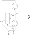
- Figure 2 shows an embodiment in which control system 40 is used to control an at least partially autonomous robot, e.g. an at least partially autonomous vehicle 100.
- Sensor 30 may comprise one or more video sensors and/or one or more radar sensors and/or one or more ultrasonic sensors and/or one or more LiDAR sensors and or one or more position sensors (like e.g. GPS). Some or all of these sensors are preferably but not necessarily integrated in vehicle 100.
- sensor 30 may comprise an information system for determining a state of the actuator system.
- One example for such an information system is a weather information system which determines a present or future state of the weather in environment 20.
- the classifier 60 may for example detect objects in the vicinity of the at least partially autonomous robot.
- Output signal y may comprise an information which characterizes where objects are located in the vicinity of the at least partially autonomous robot.
- Control command A may then be determined in accordance with this information, for example to avoid collisions with said detected objects.
- Actuator 10 which is preferably integrated in vehicle 100, may be given by a brake, a propulsion system, an engine, a drivetrain, or a steering of vehicle 100.
- Actuator control commands A may be determined such that actuator (or actuators) 10 is/are controlled such that vehicle 100 avoids collisions with said detected objects.
- Detected objects may also be classified according to what the classifier 60 deems them most likely to be, e.g. pedestrians or trees, and actuator control commands A may be determined depending on the classification.
- the at least partially autonomous robot may be given by another mobile robot (not shown), which may, for example, move by flying, swimming, diving or stepping.
- the mobile robot may, inter alia, be an at least partially autonomous lawn mower, or an at least partially autonomous cleaning robot.
- actuator command control A may be determined such that propulsion unit and/or steering and/or brake of the mobile robot are controlled such that the mobile robot may avoid collisions with said identified objects.
- the at least partially autonomous robot may be given by a gardening robot (not shown), which uses sensor 30, preferably an optical sensor, to determine a state of plants in the environment 20.
- Actuator 10 may be a nozzle for spraying chemicals.
- an actuator control command A may be determined to cause actuator 10 to spray the plants with a suitable quantity of suitable chemicals.
- the at least partially autonomous robot may be given by a domestic appliance (not shown), like e.g. a washing machine, a stove, an oven, a microwave, or a dishwasher.
- Sensor 30, e.g. an optical sensor may detect a state of an object which is to undergo processing by the household appliance.
- Sensor 30 may detect a state of the laundry inside the washing machine.
- Actuator control signal A may then be determined depending on a detected material of the laundry.
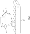
- control system 40 is used to control a manufacturing machine 11, e.g. a punch cutter, a cutter or a gun drill) of a manufacturing system 200, e.g. as part of a production line.
- the control system 40 controls an actuator 10 which in turn control the manufacturing machine 11.
- Sensor 30 may be given by an optical sensor which captures properties of e.g. a manufactured product 12.
- Classifier 60 may determine a state of the manufactured product 12 from these captured properties.
- Actuator 10 which controls manufacturing machine 11 may then be controlled depending on the determined state of the manufactured product 12 for a subsequent manufacturing step of manufactured product 12. Or, it may be envisioned that actuator 10 is controlled during manufacturing of a subsequent manufactured product 12 depending on the determined state of the manufactured product 12.
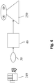
- control system 40 is used for controlling an automated personal assistant 250.
- Sensor 30 may be an optic sensor, e.g. for receiving video images of a gestures of user 249.
- sensor 30 may also be an audio sensor e.g. for receiving a voice command of user 249.
- Control system 40 determines actuator control commands A for controlling the automated personal assistant 250.
- the actuator control commands A are determined in accordance with sensor signal S from sensor 30. Sensor signal S is transmitted to the control system 40.
- classifier 60 may be configured to e.g. carry out a gesture recognition algorithm to identify a gesture made by user 249.
- Control system 40 may then determine an actuator control command A for transmission to the automated personal assistant 250. It then transmits said actuator control command A to the automated personal assistant 250.
- actuator control command A may be determined in accordance with the identified user gesture recognized by classifier 60. It may then comprise information that causes the automated personal assistant 250 to retrieve information from a database and output this retrieved information in a form suitable for reception by user 249.
- control system 40 controls a domestic appliance (not shown) controlled in accordance with the identified user gesture.
- the domestic appliance may be a washing machine, a stove, an oven, a microwave or a dishwasher.
- Access control system may be designed to physically control access. It may, for example, comprise a door 401.
- Sensor 30 is configured to detect a scene that is relevant for deciding whether access is to be granted or not. It may for example be an optical sensor for providing image or video data, for detecting a person's face.
- Classifier 60 may be configured to interpret this image or video data e.g. by matching identities with known people stored in a database, thereby determining an identity of the person.
- Actuator control signal A may then be determined depending on the interpretation of classifier 60, e.g. in accordance with the determined identity.
- Actuator 10 may be a lock which grants access or not depending on actuator control signal A.
- a non-physical, logical access control is also possible.
- control system 40 controls a surveillance system 400.
- Sensor 30 is configured to detect a scene that is under surveillance.
- Control system does not necessarily control an actuator 10, but a display 10a.
- the machine learning system 60 may determine a classification of a scene, e.g. whether the scene detected by optical sensor 30 is suspicious.
- Actuator control signal A which is transmitted to display 10a may then e.g. be configured to cause display 10a to adjust the displayed content dependent on the determined classification, e.g. to highlight an object that is deemed suspicious by machine learning system 60.
- Shown in figure 7 is an embodiment of a control system 40 for controlling an imaging system 500, for example an MRI apparatus, x-ray imaging apparatus or ultrasonic imaging apparatus.
- Sensor 30 may, for example, be an imaging sensor.
- Machine learning system 60 may then determine a classification of all or part of the sensed image. Actuator control signal A may then be chosen in accordance with this classification, thereby controlling display 10a. For example, machine learning system 60 may interpret a region of the sensed image to be potentially anomalous. In this case, actuator control signal A may be determined to cause display 10a to display the imaging and highlighting the potentially anomalous region.
- FIG 8 illustrates schematically a structure of one embodiment of classifier 60.
- Classifier 60 comprises smoothed classifier g and base classifier f , e.g. a deep neural network.
- Input signal x is inputted into smoothed classifier g , which is configured to sample a plurality of random numbers ⁇ from a standard Gaussian distribution with a predefined standard deviation ⁇ and add them onto input signal x.
- base classifier f is configured to return a corresponding classification f ( x + ⁇ ) .
- the smoothed classifier g is then configured to determine top class c A and robustness value , e.g. by using the algorithms illustrated in figures 9 and 10 , and output top class c A and robustness value collectively as output signal y. Because of the structure of classifier 60, smoothed classifier g and classifier 60 are used interchangeably.
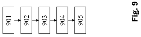
- Shown in figure 9 is a flow-chart diagram of an embodiment of a method for determining robustness value .
- First (901) a predefined number of samples n 0 is provided and n o random numbers ⁇ are sampled from the standard Gaussian distribution with a predefined standard deviation ⁇ are added onto input signal x.
- base classifier f returns a corresponding classification f ( x + ⁇ ) .
- Estimated top class c A is then determined as the class that occurs most often amongst these corresponding classifications f ( x + ⁇ ) .
- n n random numbers ⁇ are sampled from the standard Gaussian distribution with predefined standard deviation ⁇ are added onto input signal x.
- base classifier f returns a corresponding classification f ( x + ⁇ ) .
- the absolute frequency of occurrences of estimated top class c A is denoted as k.
- Figure 10 illustrates an alternative embodiment of a method for determining top class c A that is less likely to abstain if the top two classes of f ( x + ⁇ ) have similar mass.
- n random numbers ⁇ are sampled from the standard Gaussian distribution with predefined standard deviation ⁇ are added onto input signal x.
- base classifier f returns a corresponding classification f ( x + ⁇ ) .
- the top two classes c A , c B are selected as the two most frequently occurring classes amongst these classifications f ( x + ⁇ ) .
- n A and n B denote their absolute frequencies.
- n A is drawn from Binomial ( 1 2 , n A + n B ) returns a p -value of less than ⁇ . If this is the case, top class c A is returned, otherwise the algorithm abstaind.
- Shown in figure 11 is a flow-chart diagram of an embodiment of a method for determining whether classifier 60 is robust.
- input signal x which is derived from sensor signal S is provided.
- Input signal x may be noisy, because sensor signal S may be noisy.
- predefined threshold value ⁇ is provided.
- it is possible to provide environmental conditions to which sensor 30 is subjected e.g. a temperature or a humidity value of air surrounding sensor 30.
- threshold ⁇ may be determined depending on said environmental conditions, e.g. by means of a look-up table.
- Threshold ⁇ may be chosen to characterize noise produced by sensor 30, e.g.
- robustness value is provided for input signal x. Then (1400), it is determined whether robustness value is larger than ⁇ . If that is the case (1500), classifier 60 is determined to be robust. If not (1600), classifier 60 is determined not to be robust.
- Shown in figure 12 is a flow-chart diagram of an embodiment of a method for determining whether a classifier 60 is overall robust.
- a test data set comprising test input signals x i is provided (2100).
- said test data set is representative of real-world input data.
- a corresponding robustness value is determined e.g. by using the method illustrated in figure 9 and providing test input signal x i as input signal x.
- overall robustness value may be selected differently, e.g. as the median or average value of all . Then (2400), it is decided whether said overall robustness value is greater than a second threshold value ⁇ 2 , which may be provided like threshold value ⁇ in step (1200). If this is the case, classifier 60 is deemed to be overall robust (2500), if not (2600), it is deemed not to be overall robust.
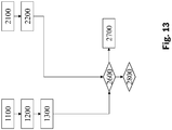
- Shown in figure 13 is a flow-chart diagram of an embodiment of a method for determining whether an input signal x is well represented in test set ⁇ x i ⁇ and hence, if classifier 60 trained using said test set is robust around input signal x.
- Steps (2100) and (2200) are identical to those in the method illustrated in figure 12
- steps (1100), (1200) and (1300) are identical to those in the method illustrated in figure 11 .
- robustness value and overall robustness value have been determined, it is checked (2600), whether they satisfy inequality R ⁇ R ov ⁇ c
- Shown in figure 14 is a flow-chart diagram of an embodiment of a method for training smoothed classifier g , which is conveniently achieved by training base classifier f associated with smoothed classifier g , and also simply referred to as 'training classifier 60'.
- classifier 60 is trained (3100). Then the overall robustness is determined based on the test set used in training and it is determined whether classifier 60 is overall robust. If this is the case, the method concludes (3300). If it is not the case, however, the method branches back to (3100) and training continues.
- An actuator control signal (A) may then (916) be determined in accordance with said parameter vu, and actuator (10) may be controlled in accordance with said actuator control signal (A). For example, if said parameter vu indicates a non-vulnerability, said actuator control signal (A) may then be determined to correspond to normal operation mode, whereas, if said parameter vu indicates a vulnerability, said actuator control signal (A) may then be determined to correspond to a fail-safe operation mode, by e.g. reducing a dynamics of a motion of said actuator (10).
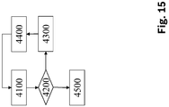
- Shown in figure 15 is a flow-chart diagram of an embodiment of a method for operating classifier 60.
- classifier 60 is operated.
- Upon being provided with a new input signal x it is determining (4200) whether classifier 60 is robust or not using the method according to claim 9. If that is not the case, the method concludes (4500). If it is the case, however, new input signal x is sent (4300) to a remote server where it may be, for example, presented to a human expert from whom said remote server receives a manual classification as target classification.
- Said target classification is then (4400) receiving, from said remote server, the pair of new input signal (x) and received target classification are added to a training set which may be used to train classifier 60 before operation resumes, or at a later point in time. The method then branches back to step (4100).
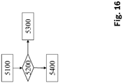
- Shown in figure 16 is a flow-chart diagram of an embodiment of a method for operating classifier 60.
- First classifier 60 is operated.
- Upon being provided with a new input signal x it is determining (5200) whether classifier 60 is robust or not using the method according to claim 9. If that is the case, the method concludes (5400), If it is not the case, however, operating parameters of sensors 30 are adjusted (5300), in particular zooming sensor 30 may zoom in on the area of new input signal x for which classifier 60 was deemed not to be robust.
- Shown in figure 17 is a flow-chart diagram of an embodiment of a method for providing actuator control signal A for controlling actuator 10 depending on an output signal y of classifier 60.
- classifier 60 is operated.
- classifier 60 is robust (6200) e.g. by using the algorithm illustrated in figure 9 .
- Actuator control signal is now determined) in accordance with the result of said assessment. If operator 60 is deemed to be robust (6300), actuator control signal A is determined to cause actuator 10 to operate in normal mode. If it is not the case, however, said actuator control signal (A) is determined to cause said actuator (10) to operate in a safe mode
- the term "computer” covers any device for the processing of pre-defined calculation instructions. These calculation instructions can be in the form of software, or in the form of hardware, or also in a mixed form of software and hardware.
Landscapes
- Engineering & Computer Science (AREA)
- Theoretical Computer Science (AREA)
- Physics & Mathematics (AREA)
- Evolutionary Computation (AREA)
- General Physics & Mathematics (AREA)
- Artificial Intelligence (AREA)
- Computer Vision & Pattern Recognition (AREA)
- Software Systems (AREA)
- Data Mining & Analysis (AREA)
- Computing Systems (AREA)
- Medical Informatics (AREA)
- General Engineering & Computer Science (AREA)
- General Health & Medical Sciences (AREA)
- Multimedia (AREA)
- Health & Medical Sciences (AREA)
- Databases & Information Systems (AREA)
- Evolutionary Biology (AREA)
- Probability & Statistics with Applications (AREA)
- Life Sciences & Earth Sciences (AREA)
- Bioinformatics & Cheminformatics (AREA)
- Bioinformatics & Computational Biology (AREA)
- Mathematical Physics (AREA)
- Algebra (AREA)
- Computational Mathematics (AREA)
- Mathematical Analysis (AREA)
- Mathematical Optimization (AREA)
- Pure & Applied Mathematics (AREA)
- Image Analysis (AREA)
- Feedback Control In General (AREA)
Abstract
- providing an input signal (x) depending on said sensor signal (S),
- determining, by the smoothed classifier (g), a first value (pA ) which characterizes a probability that said input signal (x), when subjected to noise will be classified as belonging to a first class (cA ) out of a predefined plurality of classes, wherein said first class (cA ) is a most probable class,
- determining, by the smoothed classifier (g)), a second value (pB ) which characterizes a probability that said input signal (x), when subjected to said noise (in particular Gaussian noise), will be classified as belonging to a second class (cB ) out of said predefined plurality of classes, wherein said second class (cB ) is a second-most probable class,
- determining a robustness value (

Description
- The invention concerns a method for assessing a robustness of a smoothed classifier, a method for assessing an overall robustness of a smoothed classifier, a method for training a smoothed classifier, a method for operating a smoothed classifier, a method for providing an actuator control signal, a computer program and a machine-readable storage medium.
- In safety-critical applications like, for example, highly automated driving, it is important that a classification and/or semantic segmentation of an input signal depending on which further actions of the system are selected is correct.
- However, it is well known that without appropriate counter-measures, classifiers, like e.g. neural network classification systems can easily be fooled. It is well known that classifiers which may be based on deep learning may be sensitive to small perturbations. In order to deploy such systems in the physical world it is important to provide a proof about the system's robustness.
- "Certified Robustness to Adversarial Examples with Differential Privacy", arXiv preprint arXiv:1802.03471v3, 2018, Mathias Lecuyer, Vaggelis Atlidakis, Roxana Geambasu, Daniel Hsu, Suman Jana and "Second-Order Adversarial Attack and Certifiable Robustness", arXiv preprint arXiv:1809.03113v1, 2018, Bai Li, Changyou Chen, Wenlin Wang, Lawrence Carin disclose a randomization technique to create a certifiably robust classifier based on a given classifier f, that maps an input signal to classes. Classifier f is also called a base classifier in this context. They also presented certifiably robust bounds for such a smoothed classifier.

- A smoothed classifier g may be defined as follows: When presented with an input x, the smoothed classifier g returns the most likely prediction by base classifier f under noise, in particular under random Gaussian perturbations of input signal x:
 (0,σ2 I) for some predefined variance σ 2.
- In order to be sure that the classification of said smoothed classifier g is correct, it is important to have guaranteed robustness. The method with the features of independent claim 1 yields a robustness value (also called a robustness bound)that guarantees that the classification yielded by smoothed classifier g is the same for all input vectors that lie within a ball of radius
 around input signal x.
- Therefore, in a first aspect, the invention is concerned with a computer-implemented method for assessing a robustness of a smoothed classifier (g) for classifying sensor signals received from a sensor (30), comprising the steps of:
- determining an input signal depending on said sensor signal
- determining, by the smoothed classifier (g)a first value (pA ) which characterizes a probability that said input signal (x), when subjected to noise, will be classified as belonging to a first class (cA ) out of a predefined plurality of classes, wherein said first class (cA ) is a most probable class,
- determining, by the smoothed classifier (g), a second value (pB ) which characterizes a probability that said input signal (x), when subjected to said noise will be classified as belonging to a second class (cB ) out of said predefined plurality of classes, wherein said second class (cB ) is a second-most probable class,
- determining the robustness value on a first inverse value (Φ-1(pA )) of a standard Gaussian cumulative distribution function at said first value (pA ) and/or depending on a second inverse value (Φ-1(pB )) of said standard Gaussian cumulative distribution function at said second value (pB ).

- It may then be decided that the smoothed classifier (g) is robust if and only if said robustness valueis larger than a predefined threshold.

- For example, said predefined threshold may be given by a quantity characterizing noise in said sensor signals.
- In a preferred embodiment, said robustness valueis determined proportional to Φ-1(pA ) - Φ-1(pB ), preferably σ · (Φ-1(pA ) - Φ-1(pB )).

- If it is chosen equal to


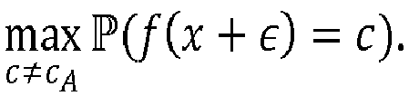 around input signal x, it is necessary to compute pA and pB. However, if the input signal is high-dimensional, it is impossible to exactly compute the distribution of f(x + ε), which is a discrete distribution over the set of possible classes
 . That is because in order to compute g(x) exactly, it is necessary to compute f(x + ε) over all possible states x + ε and integrate a Gaussian along the setSA = {x + ε|f(x + ε) = cA }.
- A good approximation can be obtained by Monte Carlo estimation to construct bounds pA and pB .that satisfy

- Estimating pA and pB while simultaneously identifying the top class cA is potentially inefficient. A straightforward implementation would compute pi =

- One way is a two-step procedure. First, use n 0 samples from f(x + ε) to take a guess
cA .at the identity of the top class cA . Since meaningfully large radii can only be certified when f(x + ε) puts almost all its mass on the top class, it is possible to take n 0 very small, e.g. n 0 = 3. Second, use n samples from f(x + ε) to obtain pA and pB that satisfy (2) with probability 1 - α for a predefined value of α. It can be observed that it is much more typical for the mass of f(x + ε) outside top class cA to be allocated entirely to one remaining class than to be spread uniformly over all remaining classes. Therefore, it is possible to determine pB as pB = 1 - pA , which is highly efficient, while at the same time being a very precise upper bound. - In a further aspect of the invention, it is possible to apply the above method to a test set comprising a plurality of test input signals (xi ). Using said test input signal (xi ) as input signal (x) as above, it is then possible to determine a plurality of test robustness values (), each corresponding to one of the test input signals (xi ). It is then possible to determine an overall robustrness value (
 ) that characterizes the determined set of test robustness values (
 ), for example its minimum value.
- It may then be decided that the smoothed classifier (g) is robust if and only if said overall robustness valueis larger than a predefined threshold.

- Alternatively, it is then possible to determine whether said smoothed classifier (g) is robust or not based on a relative size of said robustness value () and said overall robustness value (
 ). Said relative size is an indicator whether said input signal (x) is meaningfully represented by the test set, or not, or, in other words, whether said input signal (x) is representative of said test set. For example, it may be determined that said smoothed classifier (g) is robust if and only if said relative size, for example a quotient

- In a further aspect of the invention, it may be envisioned to use this decision whether the smoothed classifier (g) is robust or not as a cut-off criterion for training of said smoothed classifier (g), wherein training is continued if said smooth classifier (g) is determined to be non-robust.
- In a still further aspect of the invention, it is possible to use relative size for training during operation of said smoothed classifier. It may be envisioned to operate said smoothed classifier (g), determining whether said smoothed classifier (g) is robust or not using the above method, and, if said smoothed classifier (g) is determined to be non-robust based on said relative size, send said input signal (x) to a remote server, receive, from said remote server, a target classification of said input signal (x), and further train said smoothed classifier (g) using said input signal (x) and said target classification. For example, said target classification may have been provided by a human expert. Remote may mean that said remote server and a computer executing said smoothed classifier are not integrated in a single unit.
- In another still further aspect of the invention, it is possible to use said robustness valueas a trigger for closer inspection, by determining, using the above method, said robustness value (
 ) of said smoothed classifier (g) when provided with said input signal (x) and adjusting operating parameters of said sensor (30) depending on said robustness value. In particular, said sensor (30) may be controlled to zoom into a region that is classified as non-robust.
- In another still further aspect of the invention, it is possible to use said robustness valuefor safe operation of an actuator, by assessing whether said smoothed classifier (g) is robust or not using the above method, and determining an actuator control signal (A) for controlling said actuator in accordance with a result of said assessment, in particular by determining said actuator control signal (A) to cause said actuator to operate in a safe mode if said smoothed classifier (g) is deemed not robust as a result of said assessment.

- Naturally, the above methods are not limited in application to automated driving. In other applications, it may be envisioned to have said actuator controlling an at least partially autonomous robot (100) and/or a manufacturing machine (200)) and/or an access control system (300).
- Embodiments of the invention will be discussed with reference to the following figures in more detail. The figures show:
- Figure 1
- a control system having a classifier controlling an actuator in its environment;
- Figure 2
- the control system controlling an at least partially autonomous robot;
- Figure 3
- the control system controlling a manufacturing machine;
- Figure 4
- the control system controlling an automated personal assistant;
- Figure 5
- the control system controlling an access control system;
- Figure 6
- the control system controlling a surveillance system;
- Figure 7
- the control system controlling an imaging system;
- Figure 8
- an embodiment of a structure of said classifier;
- Figure 9
- a flow-chart diagram of an algorithm for determining robustness value
;

- Figure 10
- a flow-chart diagram of a part of an alternative algorithm for determining robustness value
;

- Figure 11
- a flow-chart diagram of a method for determining whether a classifier is robust;
- Figure 12
- a flow-chart diagram illustrating of a method for determining whether a
classifier 60 is overall robust; - Figure 13
- a flow-chart diagram for illustrating of a method for determining whether an input signal x is well represented in a test set;
- Figure 14
- a flow-chart diagram illustrating another method for operating
classifier 60; - Figure 15
- a flow-chart diagram illustrating another method for operating
classifier 60; - Figure 16
- a flow-chart diagram illustrating another method for operating
classifier 60; - Figure 17
- a flow-chart diagram illustrating a method for providing actuator control signal A.
- Shown in
figure 1 is one embodiment of anactuator 10 in itsenvironment 20.Actuator 10 interacts with acontrol system 40.Actuator 10 and itsenvironment 20 will be jointly called actuator system. At preferably evenly spaced distances, asensor 30 senses a condition of the actuator system. Thesensor 30 may comprise several sensors. Preferably,sensor 30 is an optical sensor that takes images of theenvironment 20. An output signal S of sensor 30 (or, in case thesensor 30 comprises a plurality of sensors, an output signal S for each of the sensors) which encodes the sensed condition is transmitted to thecontrol system 40. - Thereby,
control system 40 receives a stream of sensor signals S. It then computes a series of actuator control commands A depending on the stream of sensor signals S, which are then transmitted toactuator 10. -
Control system 40 receives the stream of sensor signals S ofsensor 30 in anoptional receiving unit 50. Receivingunit 50 transforms the sensor signals S into input signals x. Alternatively, in case of no receivingunit 50, each sensor signal S may directly be taken as an input signal x. Input signal x may, for example, be given as an excerpt from sensor signal S. Alternatively, sensor signal S may be processed to yield input signal x. Input signal x comprises image data corresponding to an image recorded bysensor 30. In other words, input signal x is provided in accordance with sensor signal S. - Input signal x is then passed on to a
classifier 60, which may, for example, be given by an artificial neural network. -
Classifier 60 is parametrized by parameters φ, which are stored in and provided by parameter storage St 1. -
Classifier 60 determines output signals y from input signals x. The output signal y comprises top class cA and robustness value. Naturally, top class cA and robustness value may correspond to a classification of the entire input signal x. Alternatively, it may be given as a semantic segmentation, e.g. by assigning classes to bounding boxes. Output signals y are transmitted to an
optional conversion unit 80, which is configured to determine actuator control commands A. Actuator control commands A are then transmitted toactuator 10 for controllingactuator 10 accordingly. Alternatively, output signals y may directly be taken as control commands A. -
Actuator 10 receives actuator control commands A, is controlled accordingly and carries out an action corresponding to actuator control commandsA. Actuator 10 may comprise a control logic which transforms actuator control command A into a further control command, which is then used to controlactuator 10. - In further embodiments,
control system 40 may comprisesensor 30. In even further embodiments,control system 40 alternatively or additionally may compriseactuator 10. - In still further embodiments, it may be envisioned that
control system 40 controls adisplay 10a instead of anactuator 10. - Furthermore,
control system 40 may comprise a processor 45 (or a plurality of processors) and at least one machine-readable storage medium 46 on which instructions are stored which, if carried out, causecontrol system 40 to carry out a method according to one aspect of the invention. -
Figure 2 shows an embodiment in whichcontrol system 40 is used to control an at least partially autonomous robot, e.g. an at least partiallyautonomous vehicle 100. -
Sensor 30 may comprise one or more video sensors and/or one or more radar sensors and/or one or more ultrasonic sensors and/or one or more LiDAR sensors and or one or more position sensors (like e.g. GPS). Some or all of these sensors are preferably but not necessarily integrated invehicle 100. Alternatively or additionallysensor 30 may comprise an information system for determining a state of the actuator system. One example for such an information system is a weather information system which determines a present or future state of the weather inenvironment 20. - For example, using input signal x, the
classifier 60 may for example detect objects in the vicinity of the at least partially autonomous robot. Output signal y may comprise an information which characterizes where objects are located in the vicinity of the at least partially autonomous robot. Control command A may then be determined in accordance with this information, for example to avoid collisions with said detected objects. -
Actuator 10, which is preferably integrated invehicle 100, may be given by a brake, a propulsion system, an engine, a drivetrain, or a steering ofvehicle 100. Actuator control commands A may be determined such that actuator (or actuators) 10 is/are controlled such thatvehicle 100 avoids collisions with said detected objects. Detected objects may also be classified according to what theclassifier 60 deems them most likely to be, e.g. pedestrians or trees, and actuator control commands A may be determined depending on the classification. - In further embodiments, the at least partially autonomous robot may be given by another mobile robot (not shown), which may, for example, move by flying, swimming, diving or stepping. The mobile robot may, inter alia, be an at least partially autonomous lawn mower, or an at least partially autonomous cleaning robot. In all of the above embodiments, actuator command control A may be determined such that propulsion unit and/or steering and/or brake of the mobile robot are controlled such that the mobile robot may avoid collisions with said identified objects.
- In a further embodiment, the at least partially autonomous robot may be given by a gardening robot (not shown), which uses
sensor 30, preferably an optical sensor, to determine a state of plants in theenvironment 20.Actuator 10 may be a nozzle for spraying chemicals. Depending on an identified species and/or an identified state of the plants, an actuator control command A may be determined to causeactuator 10 to spray the plants with a suitable quantity of suitable chemicals. - In even further embodiments, the at least partially autonomous robot may be given by a domestic appliance (not shown), like e.g. a washing machine, a stove, an oven, a microwave, or a dishwasher.
Sensor 30, e.g. an optical sensor, may detect a state of an object which is to undergo processing by the household appliance. For example, in the case of the domestic appliance being a washing machine,sensor 30 may detect a state of the laundry inside the washing machine. Actuator control signal A may then be determined depending on a detected material of the laundry. - Shown in
figure 3 is an embodiment in whichcontrol system 40 is used to control amanufacturing machine 11, e.g. a punch cutter, a cutter or a gun drill) of amanufacturing system 200, e.g. as part of a production line. Thecontrol system 40 controls anactuator 10 which in turn control themanufacturing machine 11. -
Sensor 30 may be given by an optical sensor which captures properties of e.g. a manufacturedproduct 12.Classifier 60 may determine a state of the manufacturedproduct 12 from these captured properties.Actuator 10 which controlsmanufacturing machine 11 may then be controlled depending on the determined state of the manufacturedproduct 12 for a subsequent manufacturing step of manufacturedproduct 12. Or, it may be envisioned thatactuator 10 is controlled during manufacturing of a subsequent manufacturedproduct 12 depending on the determined state of the manufacturedproduct 12. - Shown in
figure 4 is an embodiment in whichcontrol system 40 is used for controlling an automatedpersonal assistant 250.Sensor 30 may be an optic sensor, e.g. for receiving video images of a gestures ofuser 249. Alternatively,sensor 30 may also be an audio sensor e.g. for receiving a voice command ofuser 249. -
Control system 40 then determines actuator control commands A for controlling the automatedpersonal assistant 250. The actuator control commands A are determined in accordance with sensor signal S fromsensor 30. Sensor signal S is transmitted to thecontrol system 40. For example,classifier 60 may be configured to e.g. carry out a gesture recognition algorithm to identify a gesture made byuser 249.Control system 40 may then determine an actuator control command A for transmission to the automatedpersonal assistant 250. It then transmits said actuator control command A to the automatedpersonal assistant 250. - For example, actuator control command A may be determined in accordance with the identified user gesture recognized by
classifier 60. It may then comprise information that causes the automatedpersonal assistant 250 to retrieve information from a database and output this retrieved information in a form suitable for reception byuser 249. - In further embodiments, it may be envisioned that instead of the automated
personal assistant 250,control system 40 controls a domestic appliance (not shown) controlled in accordance with the identified user gesture. The domestic appliance may be a washing machine, a stove, an oven, a microwave or a dishwasher. - Shown in
figure 5 is an embodiment in which control system controls anaccess control system 300. Access control system may be designed to physically control access. It may, for example, comprise adoor 401.Sensor 30 is configured to detect a scene that is relevant for deciding whether access is to be granted or not. It may for example be an optical sensor for providing image or video data, for detecting a person's face.Classifier 60 may be configured to interpret this image or video data e.g. by matching identities with known people stored in a database, thereby determining an identity of the person. Actuator control signal A may then be determined depending on the interpretation ofclassifier 60, e.g. in accordance with the determined identity.Actuator 10 may be a lock which grants access or not depending on actuator control signal A. A non-physical, logical access control is also possible. - Shown in
figure 6 is an embodiment in whichcontrol system 40 controls asurveillance system 400. This embodiment is largely identical to the embodiment shown infigure 5 . Therefore, only the differing aspects will be described in detail.Sensor 30 is configured to detect a scene that is under surveillance. Control system does not necessarily control anactuator 10, but adisplay 10a. For example, themachine learning system 60 may determine a classification of a scene, e.g. whether the scene detected byoptical sensor 30 is suspicious. Actuator control signal A which is transmitted todisplay 10a may then e.g. be configured to causedisplay 10a to adjust the displayed content dependent on the determined classification, e.g. to highlight an object that is deemed suspicious bymachine learning system 60. - Shown in
figure 7 is an embodiment of acontrol system 40 for controlling animaging system 500, for example an MRI apparatus, x-ray imaging apparatus or ultrasonic imaging apparatus.Sensor 30 may, for example, be an imaging sensor.Machine learning system 60 may then determine a classification of all or part of the sensed image. Actuator control signal A may then be chosen in accordance with this classification, thereby controllingdisplay 10a. For example,machine learning system 60 may interpret a region of the sensed image to be potentially anomalous. In this case, actuator control signal A may be determined to causedisplay 10a to display the imaging and highlighting the potentially anomalous region. -
Figure 8 illustrates schematically a structure of one embodiment ofclassifier 60.Classifier 60 comprises smoothed classifier g and base classifier f, e.g. a deep neural network. Input signal x is inputted into smoothed classifier g, which is configured to sample a plurality of random numbers ε from a standard Gaussian distribution with a predefined standard deviation σ and add them onto input signal x. For each random number ε, base classifier f is configured to return a corresponding classification f(x + ε). Using this plurality of classifications f(x + ε), the smoothed classifier g is then configured to determine top class cA and robustness value, e.g. by using the algorithms illustrated in
figures 9 and10 , and output top class cA and robustness valuecollectively as output signal y. Because of the structure of
classifier 60, smoothed classifier g andclassifier 60 are used interchangeably. - Shown in
figure 9 is a flow-chart diagram of an embodiment of a method for determining robustness value. First (901), a predefined number of samples n 0 is provided and no random numbers ε are sampled from the standard Gaussian distribution with a predefined standard deviation σ are added onto input signal x. For each random number ε, base classifier f returns a corresponding classification f(x + ε). Estimated top class
cA is then determined as the class that occurs most often amongst these corresponding classifications f(x + ε). - Then (902), a predefined second number of samples n is provided and n random numbers ε are sampled from the standard Gaussian distribution with predefined standard deviation σ are added onto input signal x. For each random number ε, base classifier f returns a corresponding classification f(x + ε). By counting the number of occurrences of estimated top class
cA , a relative frequency
cA is computed. Here, the absolute frequency of occurrences of estimated top classcA is denoted as k. - Next (903), because the statistical sample with n data points is subject to fluctuations, lower bound pA satisfying

- For example one could use the following formula with Fa,b,c being the 1 - c quantile of the F-distribution with parameters a and b. Then, the lower bound pA may be given by equation

- Upper bound pB is computed as pB = 1 - pA.
- Then (905) it is checked whether pA ≥ pB, in which case the robustness valueis computed using equation (2). If pA < pB, the algorithm abstains and issues a default error message, e.g. by setting


-
Figure 10 illustrates an alternative embodiment of a method for determining top class cA that is less likely to abstain if the top two classes of f(x + ε) have similar mass. First (911), n random numbers ε are sampled from the standard Gaussian distribution with predefined standard deviation σ are added onto input signal x. For each random number ε, base classifier f returns a corresponding classification f(x + ε).
Then (912) the top two classes cA, cB are selected as the two most frequently occurring classes amongst these classifications f(x + ε). nA and nB denote their absolute frequencies. Then, it is checked whether the two-sided binomial hypothesis test that nA is drawn from Binomial (
- Shown in
figure 11 is a flow-chart diagram of an embodiment of a method for determining whetherclassifier 60 is robust. First (1100), input signal x which is derived from sensor signal S is provided. Input signal x may be noisy, because sensor signal S may be noisy. Then (1200), predefined threshold value τ is provided. For example, it is possible to provide environmental conditions to whichsensor 30 is subjected, e.g. a temperature or a humidity value ofair surrounding sensor 30. Then, threshold τ may be determined depending on said environmental conditions, e.g. by means of a look-up table. Threshold τ may be chosen to characterize noise produced bysensor 30, e.g. a standard deviation or statistical variations of pixel values, ifsensor 30 is an image or video sensor. Then, robustness valueis provided for input signal x. Then (1400), it is determined whether robustness value is larger than τ. If that is the case (1500),
classifier 60 is determined to be robust. If not (1600),classifier 60 is determined not to be robust. - Shown in
figure 12 is a flow-chart diagram of an embodiment of a method for determining whether aclassifier 60 is overall robust. To this end, a test data set comprising test input signals xi is provided (2100). Preferably, said test data set is representative of real-world input data. Then (2200), for each test input signal xi , a corresponding robustness valueis determined e.g. by using the method illustrated in
figure 9 and providing test input signal xi as input signal x. Next (2300), overall robustness valueis determined from the set of robustness values { } by taking a value that characterizes this set, e.g. the minimum value, i.e.
 . Then (2400), it is decided whether said overall robustness value
 is greater than a second threshold value τ 2, which may be provided like threshold value τ in step (1200). If this is the case,
classifier 60 is deemed to be overall robust (2500), if not (2600), it is deemed not to be overall robust. - Shown in
figure 13 is a flow-chart diagram of an embodiment of a method for determining whether an input signal x is well represented in test set {xi } and hence, ifclassifier 60 trained using said test set is robust around input signal x. - Steps (2100) and (2200) are identical to those in the method illustrated in
figure 12 , steps (1100), (1200) and (1300) are identical to those in the method illustrated infigure 11 . After robustness valueand overall robustness value have been determined, it is checked (2600), whether they satisfy inequality

- If this is the case (2700), input signal x is deemed not to be well represented in the test set and hence
classifier 60 trained using the test set is deemed not robust. If this is not the case (2800), input signal x is deemed to be well represented in the test set, and henceclassifier 60 is deemed to be robust. - Shown in
figure 14 is a flow-chart diagram of an embodiment of a method for training smoothed classifier g, which is conveniently achieved by training base classifier f associated with smoothed classifier g, and also simply referred to as 'training classifier 60'. First,classifier 60 is trained (3100). Then the overall robustnessis determined based on the test set used in training and it is determined whether
classifier 60 is overall robust. If this is the case, the method concludes (3300). If it is not the case, however, the method branches back to (3100) and training continues. - An actuator control signal (A) may then (916) be determined in accordance with said parameter vu, and actuator (10) may be controlled in accordance with said actuator control signal (A). For example, if said parameter vu indicates a non-vulnerability, said actuator control signal (A) may then be determined to correspond to normal operation mode, whereas, if said parameter vu indicates a vulnerability, said actuator control signal (A) may then be determined to correspond to a fail-safe operation mode, by e.g. reducing a dynamics of a motion of said actuator (10).
- Shown in
figure 15 is a flow-chart diagram of an embodiment of a method for operatingclassifier 60. First (4100),classifier 60 is operated. Upon being provided with a new input signal x, it is determining (4200) whetherclassifier 60 is robust or not using the method according toclaim 9. If that is not the case, the method concludes (4500). If it is the case, however, new input signal x is sent (4300) to a remote server where it may be, for example, presented to a human expert from whom said remote server receives a manual classification as target classification. Said target classification is then (4400) receiving, from said remote server, the pair of new input signal (x) and received target classification are added to a training set which may be used to trainclassifier 60 before operation resumes, or at a later point in time. The method then branches back to step (4100). - Shown in
figure 16 is a flow-chart diagram of an embodiment of a method for operatingclassifier 60. First (5100),classifier 60 is operated. Upon being provided with a new input signal x, it is determining (5200) whetherclassifier 60 is robust or not using the method according toclaim 9. If that is the case, the method concludes (5400), If it is not the case, however, operating parameters ofsensors 30 are adjusted (5300), inparticular zooming sensor 30 may zoom in on the area of new input signal x for whichclassifier 60 was deemed not to be robust. - Shown in
figure 17 is a flow-chart diagram of an embodiment of a method for providing actuator control signal A for controllingactuator 10 depending on an output signal y ofclassifier 60. First (6100),classifier 60 is operated. Upon being provided with a new input signal x, it is determined whetherclassifier 60 is robust (6200) e.g. by using the algorithm illustrated infigure 9 . Actuator control signal is now determined) in accordance with the result of said assessment. Ifoperator 60 is deemed to be robust (6300), actuator control signal A is determined to causeactuator 10 to operate in normal mode. If it is not the case, however, said actuator control signal (A) is determined to cause said actuator (10) to operate in a safe mode - The term "computer" covers any device for the processing of pre-defined calculation instructions. These calculation instructions can be in the form of software, or in the form of hardware, or also in a mixed form of software and hardware.
- It is further understood that the procedures cannot only be completely implemented in software as described. They can also be implemented in hardware, or in a mixed form of software and hardware.
Claims (16)
- A computer-implemented method for assessing a robustness of a smoothed classifier (g) for classifying sensor signals received from a sensor (30), comprising the steps of:- providing an input signal (x) depending on said sensor signal (S),- determining, by the smoothed classifier (g), a first value (pA ) which characterizes a probability that said input signal (x), when subjected to noise, will be classified as belonging to a first class (cA ) out of a predefined plurality of classes, wherein said first class (cA ) is a most probable class,- determining, by the smoothed classifier (g)), a second value (pB ) which characterizes a probability that said input signal (x), when subjected to said noise, will be classified as belonging to a second class (cB ) out of said predefined plurality of classes, wherein said second class (cB ) is a second-most probable class,- determining a robustness value () on a first inverse value (Φ-1(pA )) of a standard Gaussian cumulative distribution function (Φ) at said first value (pA ) and/or depending on a second inverse value (Φ-1(pB )) of said standard Gaussian cumulative distribution function (Φ) at said second value (pB ).

- The method according to claim 1, wherein said robustness value () is determined depending on a product of a standard deviation (σ) and a difference of said first inverse value (Φ-1(pA )) minus said second inverse value (Φ-1(pB )).

- The method according to any one of claims 1 and 2, in which prior to determining said first value (pA ), the method comprises the step of estimating which class out of said predefined plurality of classes is said first class (cA ).
- The method according to any one of claims 1 to 3, wherein said first value (pA ) is a lower bound to the probability that said input signal (x), when subjected to said noise will be classified as belonging to said first class (cA ).
- The method according to any one of claims 1 to 4, wherein said second value (pB ) is an upper bound to the probability that said input signal (x), when subjected to said noise will be classified as belonging to said second class (cB ).
- The method according to claim 5, in which said second value (pB ) is determined as pB = 1 - pA
- The method according to any one of the above claims, wherein said robustness value () is determined depending on a product of a standard deviation (σ) and a difference of said first inverse value (Φ-1(pA )) minus said second inverse value (Φ-1(pB )).

- A computer-implemented method for assessing an overall robustness () of a smoothed classifier (g) for classifying sensor signals received from a sensor (30), comprising the steps of:
 - providing a training set comprising test input signals (xi)- determining a test robustness value for each of said test input signals (xi) by using the method according to any one of claims 1 to 7 and using said test input signal (xi) as said input signal (x) instead of receiving it from said sensor (30),- determining said overall robustness () as a value that characterizes the determined set of test robustness values (
 ), in particular its minimum value.
- The computer-implemented method according to claim 1 and 7, wherein it is determined whether said smoothed classifier (g) is robust or not based on a relative size of said robustness value () and said overall robustness value (
 ).
).
- A computer-implemented method for training a smoothed classifier (g), comprising the steps of:- training said smoothed classifier (g),- determining whether the classifier (g) is robust using the method of claim 8- continuing training if said smooth classifier (g) is determined to be non-robust.
- A computer-implemented method for operating a smoothed classifier (g), comprising the steps of:- determining whether said smoothed classifier (g) is robust or not using the method according to claim 9, and, if said smoothed classifier (g) is determined to be non-robust:- sending said input signal (x) to a remote server- receiving, from said remote server, a target classification of said input signal (x), and- further training said smoothed classifier (g) using said input signal (x) and said target classification.
- A computer-implemented method for operating a system comprising a smoothed classifier (g) and a sensor (30) providing input signal (x) to said smoothed classifier (g), comprising the steps of- determining, using the method according to any of claims 1 to 7, a robustness value () of said smoothed classifier (g) when provided with said input signal (x);
 - adjusting operating parameters, in particular zooming in, of said sensor (30) depending on said robustness value ().
- A computer-implemented method for providing an actuator control signal (A) for controlling an actuator (10) depending on an output signal (y) of a smoothed classifier (60), comprising the steps of:- assessing whether said smoothed classifier (g) is robust or not using the method according any one of claims 1 to 7, and determining said actuator control signal (A) in accordance with a result of said assessment, in particular by determining said actuator control signal (A) to cause said actuator (10) to operate in a safe mode if said smoothed classifier (g) is deemed not robust as a result of said assessment.
- The method according to any one of claims 13, in which said actuator (10) controls an at least partially autonomous robot (100) and/or a manufacturing machine (200)) and/or an access control system (300).
- Computer program that is configured to cause a computer to carry out the method according to any one of claims 1 to 14 with all of its steps if the computer program is carried out by a processor (45, 145).
- Machine-readable storage medium (46, 146) on which the computer program according to claim 15 is stored.
Priority Applications (5)
| Application Number | Priority Date | Filing Date | Title |
|---|---|---|---|
| EP19155345.2A EP3690760B1 (en) | 2019-02-04 | 2019-02-04 | Device and method to improve the robustness against adversarial examples |
| US17/272,435 US12254384B2 (en) | 2019-02-04 | 2020-01-10 | Device and method to improve the robustness against ‘adversarial examples’ |
| CN202080012339.7A CN113348475B (en) | 2019-02-04 | 2020-01-10 | Apparatus and method for improving robustness against "challenge examples |
| PCT/IB2020/050176 WO2020161546A1 (en) | 2019-02-04 | 2020-01-10 | Device and method to improve the robustness against adversarial examples |
| JP2021545397A JP7264412B2 (en) | 2019-02-04 | 2020-01-10 | Device and method for improving robustness against adversarial samples |
Applications Claiming Priority (1)
| Application Number | Priority Date | Filing Date | Title |
|---|---|---|---|
| EP19155345.2A EP3690760B1 (en) | 2019-02-04 | 2019-02-04 | Device and method to improve the robustness against adversarial examples |
Publications (2)
| Publication Number | Publication Date |
|---|---|
| EP3690760A1 true EP3690760A1 (en) | 2020-08-05 |
| EP3690760B1 EP3690760B1 (en) | 2022-10-26 |
Family
ID=65279479
Family Applications (1)
| Application Number | Title | Priority Date | Filing Date |
|---|---|---|---|
| EP19155345.2A Active EP3690760B1 (en) | 2019-02-04 | 2019-02-04 | Device and method to improve the robustness against adversarial examples |
Country Status (5)
| Country | Link |
|---|---|
| US (1) | US12254384B2 (en) |
| EP (1) | EP3690760B1 (en) |
| JP (1) | JP7264412B2 (en) |
| CN (1) | CN113348475B (en) |
| WO (1) | WO2020161546A1 (en) |
Cited By (1)
| Publication number | Priority date | Publication date | Assignee | Title |
|---|---|---|---|---|
| JP2023541450A (en) * | 2020-09-15 | 2023-10-02 | ローベルト ボツシユ ゲゼルシヤフト ミツト ベシユレンクテル ハフツング | Apparatus and method for classifying images and accessing robustness of classification |
Family Cites Families (7)
| Publication number | Priority date | Publication date | Assignee | Title |
|---|---|---|---|---|
| US5745601A (en) | 1995-07-31 | 1998-04-28 | Neopath, Inc. | Robustness of classification measurement apparatus and method |
| US10013477B2 (en) * | 2012-11-19 | 2018-07-03 | The Penn State Research Foundation | Accelerated discrete distribution clustering under wasserstein distance |
| BR112017017079A2 (en) * | 2015-02-12 | 2018-04-10 | Koninklijke Philips N.V. | robust classification apparatus, processor-based method, and computer readable non-transient media |
| CN104966105A (en) * | 2015-07-13 | 2015-10-07 | 苏州大学 | Robust machine error retrieving method and system |
| US11263545B2 (en) * | 2016-06-30 | 2022-03-01 | Microsoft Technology Licensing, Llc | Control of cyber-physical systems under uncertainty |
| DE102017209496B4 (en) | 2017-06-06 | 2020-10-01 | Robert Bosch Gmbh | Method and device for classifying an object for a vehicle |
| CN107463951A (en) | 2017-07-19 | 2017-12-12 | 清华大学 | A kind of method and device for improving deep learning model robustness |
-
2019
- 2019-02-04 EP EP19155345.2A patent/EP3690760B1/en active Active
-
2020
- 2020-01-10 JP JP2021545397A patent/JP7264412B2/en active Active
- 2020-01-10 WO PCT/IB2020/050176 patent/WO2020161546A1/en not_active Ceased
- 2020-01-10 CN CN202080012339.7A patent/CN113348475B/en active Active
- 2020-01-10 US US17/272,435 patent/US12254384B2/en active Active
Non-Patent Citations (5)
| Title |
|---|
| BAI LI ET AL: "Second-Order Adversarial Attack and Certifiable Robustness", ARXIV.ORG, CORNELL UNIVERSITY LIBRARY, 201 OLIN LIBRARY CORNELL UNIVERSITY ITHACA, NY 14853, 10 September 2018 (2018-09-10), XP081189094 * |
| BAI LI; CHANGYOU CHEN; WENLIN WANG; LAWRENCE CARIN: "Second-Order Adversarial Attack and Certifiable Robustness", ARXIV PREPRINT ARXIV:1809.03113V1, 2018 |
| HOUPU YAO ET AL: "Improving Model Robustness with Transformation-Invariant Attacks", ARXIV.ORG, CORNELL UNIVERSITY LIBRARY, 201 OLIN LIBRARY CORNELL UNIVERSITY ITHACA, NY 14853, 31 January 2019 (2019-01-31), XP081013096 * |
| MATHIAS LECUYER; VAGGELIS ATLIDAKIS; ROXANA GEAMBASU; DANIEL HSU; SUMAN JANA: "Certified Robustness to Adversarial Examples with Differential Privacy", ARXIV PREPRINT ARXIV:1802.03471V3, 2018 |
| PAPERNOT NICOLAS ET AL: "Distillation as a Defense to Adversarial Perturbations Against Deep Neural Networks", 2016 IEEE SYMPOSIUM ON SECURITY AND PRIVACY (SP), IEEE, 22 May 2016 (2016-05-22), pages 582 - 597, XP032945721, DOI: 10.1109/SP.2016.41 * |
Cited By (2)
| Publication number | Priority date | Publication date | Assignee | Title |
|---|---|---|---|---|
| JP2023541450A (en) * | 2020-09-15 | 2023-10-02 | ローベルト ボツシユ ゲゼルシヤフト ミツト ベシユレンクテル ハフツング | Apparatus and method for classifying images and accessing robustness of classification |
| US12456284B2 (en) | 2020-09-15 | 2025-10-28 | Robert Bosch Gmbh | Device and method for classifying images and accessing the robustness of the classification |
Also Published As
| Publication number | Publication date |
|---|---|
| CN113348475B (en) | 2025-08-01 |
| US12254384B2 (en) | 2025-03-18 |
| JP2022519594A (en) | 2022-03-24 |
| EP3690760B1 (en) | 2022-10-26 |
| US20210319268A1 (en) | 2021-10-14 |
| JP7264412B2 (en) | 2023-04-25 |
| WO2020161546A1 (en) | 2020-08-13 |
| CN113348475A (en) | 2021-09-03 |
Similar Documents
| Publication | Publication Date | Title |
|---|---|---|
| EP3576021A1 (en) | Method, apparatus and computer program for generating robust automated learning systems and testing trained automated learning systems | |
| US12050990B2 (en) | Device and method for training an augmented discriminator | |
| US12159447B2 (en) | Device and method for training a classifier | |
| US20230259658A1 (en) | Device and method for determining adversarial patches for a machine learning system | |
| US20220019890A1 (en) | Method and device for creating a machine learning system | |
| KR20210068993A (en) | Device and method for training a classifier | |
| US20220101129A1 (en) | Device and method for classifying an input signal using an invertible factorization model | |
| EP3754557A1 (en) | Robustness indicator unit, certificate determination unit, training unit, control unit and computer-implemented method to determine a robustness indicator | |
| US20230418246A1 (en) | Device and method for determining adversarial perturbations of a machine learning system | |
| US12254384B2 (en) | Device and method to improve the robustness against ‘adversarial examples’ | |
| EP3671574B1 (en) | Device and method to improve the robustness against adversarial examples | |
| EP3968214A1 (en) | Device and method for classifying images and accessing the robustness of the classification | |
| US20230072747A1 (en) | Device and method for training a neural network for image analysis | |
| US20240135699A1 (en) | Device and method for determining an encoder configured image analysis | |
| US12468937B2 (en) | Device and method for training a classifier using an invertible factorization model | |
| US20230368007A1 (en) | Neural network layer for non-linear normalization | |
| US12254675B2 (en) | Training of machine learning systems for image processing | |
| EP4343619A1 (en) | Method for regularizing a neural network |
Legal Events
| Date | Code | Title | Description |
|---|---|---|---|
| PUAI | Public reference made under article 153(3) epc to a published international application that has entered the european phase |
Free format text: ORIGINAL CODE: 0009012 |
|
| STAA | Information on the status of an ep patent application or granted ep patent |
Free format text: STATUS: THE APPLICATION HAS BEEN PUBLISHED |
|
| AK | Designated contracting states |
Kind code of ref document: A1 Designated state(s): AL AT BE BG CH CY CZ DE DK EE ES FI FR GB GR HR HU IE IS IT LI LT LU LV MC MK MT NL NO PL PT RO RS SE SI SK SM TR |
|
| AX | Request for extension of the european patent |
Extension state: BA ME |
|
| STAA | Information on the status of an ep patent application or granted ep patent |
Free format text: STATUS: REQUEST FOR EXAMINATION WAS MADE |
|
| STAA | Information on the status of an ep patent application or granted ep patent |
Free format text: STATUS: EXAMINATION IS IN PROGRESS |
|
| 17P | Request for examination filed |
Effective date: 20210205 |
|
| RBV | Designated contracting states (corrected) |
Designated state(s): AL AT BE BG CH CY CZ DE DK EE ES FI FR GB GR HR HU IE IS IT LI LT LU LV MC MK MT NL NO PL PT RO RS SE SI SK SM TR |
|
| 17Q | First examination report despatched |
Effective date: 20210305 |
|
| REG | Reference to a national code |
Ref country code: DE Ref legal event code: R079 Ref document number: 602019020957 Country of ref document: DE Free format text: PREVIOUS MAIN CLASS: G06N0020000000 Ipc: G06V0010820000 |
|
| GRAP | Despatch of communication of intention to grant a patent |
Free format text: ORIGINAL CODE: EPIDOSNIGR1 |
|
| STAA | Information on the status of an ep patent application or granted ep patent |
Free format text: STATUS: GRANT OF PATENT IS INTENDED |
|
| RIC1 | Information provided on ipc code assigned before grant |
Ipc: G06K 9/62 20060101ALI20220608BHEP Ipc: G06N 20/00 20190101ALI20220608BHEP Ipc: G06V 10/82 20220101AFI20220608BHEP |
|
| INTG | Intention to grant announced |
Effective date: 20220701 |
|
| GRAS | Grant fee paid |
Free format text: ORIGINAL CODE: EPIDOSNIGR3 |
|
| GRAA | (expected) grant |
Free format text: ORIGINAL CODE: 0009210 |
|
| STAA | Information on the status of an ep patent application or granted ep patent |
Free format text: STATUS: THE PATENT HAS BEEN GRANTED |
|
| AK | Designated contracting states |
Kind code of ref document: B1 Designated state(s): AL AT BE BG CH CY CZ DE DK EE ES FI FR GB GR HR HU IE IS IT LI LT LU LV MC MK MT NL NO PL PT RO RS SE SI SK SM TR |
|
| REG | Reference to a national code |
Ref country code: GB Ref legal event code: FG4D |
|
| REG | Reference to a national code |
Ref country code: CH Ref legal event code: EP |
|
| REG | Reference to a national code |
Ref country code: DE Ref legal event code: R096 Ref document number: 602019020957 Country of ref document: DE |
|
| REG | Reference to a national code |
Ref country code: AT Ref legal event code: REF Ref document number: 1527615 Country of ref document: AT Kind code of ref document: T Effective date: 20221115 |
|
| REG | Reference to a national code |
Ref country code: IE Ref legal event code: FG4D |
|
| REG | Reference to a national code |
Ref country code: LT Ref legal event code: MG9D |
|
| REG | Reference to a national code |
Ref country code: NL Ref legal event code: MP Effective date: 20221026 |
|
| REG | Reference to a national code |
Ref country code: AT Ref legal event code: MK05 Ref document number: 1527615 Country of ref document: AT Kind code of ref document: T Effective date: 20221026 |
|
| PG25 | Lapsed in a contracting state [announced via postgrant information from national office to epo] |
Ref country code: NL Free format text: LAPSE BECAUSE OF FAILURE TO SUBMIT A TRANSLATION OF THE DESCRIPTION OR TO PAY THE FEE WITHIN THE PRESCRIBED TIME-LIMIT Effective date: 20221026 |
|
| PG25 | Lapsed in a contracting state [announced via postgrant information from national office to epo] |
Ref country code: SE Free format text: LAPSE BECAUSE OF FAILURE TO SUBMIT A TRANSLATION OF THE DESCRIPTION OR TO PAY THE FEE WITHIN THE PRESCRIBED TIME-LIMIT Effective date: 20221026 Ref country code: PT Free format text: LAPSE BECAUSE OF FAILURE TO SUBMIT A TRANSLATION OF THE DESCRIPTION OR TO PAY THE FEE WITHIN THE PRESCRIBED TIME-LIMIT Effective date: 20230227 Ref country code: NO Free format text: LAPSE BECAUSE OF FAILURE TO SUBMIT A TRANSLATION OF THE DESCRIPTION OR TO PAY THE FEE WITHIN THE PRESCRIBED TIME-LIMIT Effective date: 20230126 Ref country code: LT Free format text: LAPSE BECAUSE OF FAILURE TO SUBMIT A TRANSLATION OF THE DESCRIPTION OR TO PAY THE FEE WITHIN THE PRESCRIBED TIME-LIMIT Effective date: 20221026 Ref country code: FI Free format text: LAPSE BECAUSE OF FAILURE TO SUBMIT A TRANSLATION OF THE DESCRIPTION OR TO PAY THE FEE WITHIN THE PRESCRIBED TIME-LIMIT Effective date: 20221026 Ref country code: ES Free format text: LAPSE BECAUSE OF FAILURE TO SUBMIT A TRANSLATION OF THE DESCRIPTION OR TO PAY THE FEE WITHIN THE PRESCRIBED TIME-LIMIT Effective date: 20221026 Ref country code: AT Free format text: LAPSE BECAUSE OF FAILURE TO SUBMIT A TRANSLATION OF THE DESCRIPTION OR TO PAY THE FEE WITHIN THE PRESCRIBED TIME-LIMIT Effective date: 20221026 |
|
| PG25 | Lapsed in a contracting state [announced via postgrant information from national office to epo] |
Ref country code: RS Free format text: LAPSE BECAUSE OF FAILURE TO SUBMIT A TRANSLATION OF THE DESCRIPTION OR TO PAY THE FEE WITHIN THE PRESCRIBED TIME-LIMIT Effective date: 20221026 Ref country code: PL Free format text: LAPSE BECAUSE OF FAILURE TO SUBMIT A TRANSLATION OF THE DESCRIPTION OR TO PAY THE FEE WITHIN THE PRESCRIBED TIME-LIMIT Effective date: 20221026 Ref country code: LV Free format text: LAPSE BECAUSE OF FAILURE TO SUBMIT A TRANSLATION OF THE DESCRIPTION OR TO PAY THE FEE WITHIN THE PRESCRIBED TIME-LIMIT Effective date: 20221026 Ref country code: IS Free format text: LAPSE BECAUSE OF FAILURE TO SUBMIT A TRANSLATION OF THE DESCRIPTION OR TO PAY THE FEE WITHIN THE PRESCRIBED TIME-LIMIT Effective date: 20230226 Ref country code: HR Free format text: LAPSE BECAUSE OF FAILURE TO SUBMIT A TRANSLATION OF THE DESCRIPTION OR TO PAY THE FEE WITHIN THE PRESCRIBED TIME-LIMIT Effective date: 20221026 Ref country code: GR Free format text: LAPSE BECAUSE OF FAILURE TO SUBMIT A TRANSLATION OF THE DESCRIPTION OR TO PAY THE FEE WITHIN THE PRESCRIBED TIME-LIMIT Effective date: 20230127 |
|
| REG | Reference to a national code |
Ref country code: DE Ref legal event code: R097 Ref document number: 602019020957 Country of ref document: DE |
|
| PG25 | Lapsed in a contracting state [announced via postgrant information from national office to epo] |
Ref country code: SM Free format text: LAPSE BECAUSE OF FAILURE TO SUBMIT A TRANSLATION OF THE DESCRIPTION OR TO PAY THE FEE WITHIN THE PRESCRIBED TIME-LIMIT Effective date: 20221026 Ref country code: RO Free format text: LAPSE BECAUSE OF FAILURE TO SUBMIT A TRANSLATION OF THE DESCRIPTION OR TO PAY THE FEE WITHIN THE PRESCRIBED TIME-LIMIT Effective date: 20221026 Ref country code: EE Free format text: LAPSE BECAUSE OF FAILURE TO SUBMIT A TRANSLATION OF THE DESCRIPTION OR TO PAY THE FEE WITHIN THE PRESCRIBED TIME-LIMIT Effective date: 20221026 Ref country code: DK Free format text: LAPSE BECAUSE OF FAILURE TO SUBMIT A TRANSLATION OF THE DESCRIPTION OR TO PAY THE FEE WITHIN THE PRESCRIBED TIME-LIMIT Effective date: 20221026 Ref country code: CZ Free format text: LAPSE BECAUSE OF FAILURE TO SUBMIT A TRANSLATION OF THE DESCRIPTION OR TO PAY THE FEE WITHIN THE PRESCRIBED TIME-LIMIT Effective date: 20221026 |
|
| PG25 | Lapsed in a contracting state [announced via postgrant information from national office to epo] |
Ref country code: SK Free format text: LAPSE BECAUSE OF FAILURE TO SUBMIT A TRANSLATION OF THE DESCRIPTION OR TO PAY THE FEE WITHIN THE PRESCRIBED TIME-LIMIT Effective date: 20221026 Ref country code: AL Free format text: LAPSE BECAUSE OF FAILURE TO SUBMIT A TRANSLATION OF THE DESCRIPTION OR TO PAY THE FEE WITHIN THE PRESCRIBED TIME-LIMIT Effective date: 20221026 |
|
| PLBE | No opposition filed within time limit |
Free format text: ORIGINAL CODE: 0009261 |
|
| STAA | Information on the status of an ep patent application or granted ep patent |
Free format text: STATUS: NO OPPOSITION FILED WITHIN TIME LIMIT |
|
| PG25 | Lapsed in a contracting state [announced via postgrant information from national office to epo] |
Ref country code: MC Free format text: LAPSE BECAUSE OF FAILURE TO SUBMIT A TRANSLATION OF THE DESCRIPTION OR TO PAY THE FEE WITHIN THE PRESCRIBED TIME-LIMIT Effective date: 20221026 |
|
| REG | Reference to a national code |
Ref country code: CH Ref legal event code: PL |
|
| 26N | No opposition filed |
Effective date: 20230727 |
|
| REG | Reference to a national code |
Ref country code: BE Ref legal event code: MM Effective date: 20230228 |
|
| GBPC | Gb: european patent ceased through non-payment of renewal fee |
Effective date: 20230204 |
|
| PG25 | Lapsed in a contracting state [announced via postgrant information from national office to epo] |
Ref country code: LU Free format text: LAPSE BECAUSE OF NON-PAYMENT OF DUE FEES Effective date: 20230204 Ref country code: LI Free format text: LAPSE BECAUSE OF NON-PAYMENT OF DUE FEES Effective date: 20230228 Ref country code: CH Free format text: LAPSE BECAUSE OF NON-PAYMENT OF DUE FEES Effective date: 20230228 |
|
| PG25 | Lapsed in a contracting state [announced via postgrant information from national office to epo] |
Ref country code: SI Free format text: LAPSE BECAUSE OF FAILURE TO SUBMIT A TRANSLATION OF THE DESCRIPTION OR TO PAY THE FEE WITHIN THE PRESCRIBED TIME-LIMIT Effective date: 20221026 |
|
| REG | Reference to a national code |
Ref country code: IE Ref legal event code: MM4A |
|
| PG25 | Lapsed in a contracting state [announced via postgrant information from national office to epo] |
Ref country code: GB Free format text: LAPSE BECAUSE OF NON-PAYMENT OF DUE FEES Effective date: 20230204 |
|
| PG25 | Lapsed in a contracting state [announced via postgrant information from national office to epo] |
Ref country code: IE Free format text: LAPSE BECAUSE OF NON-PAYMENT OF DUE FEES Effective date: 20230204 Ref country code: GB Free format text: LAPSE BECAUSE OF NON-PAYMENT OF DUE FEES Effective date: 20230204 Ref country code: FR Free format text: LAPSE BECAUSE OF NON-PAYMENT OF DUE FEES Effective date: 20230228 |
|
| PG25 | Lapsed in a contracting state [announced via postgrant information from national office to epo] |
Ref country code: BE Free format text: LAPSE BECAUSE OF NON-PAYMENT OF DUE FEES Effective date: 20230228 |
|
| PG25 | Lapsed in a contracting state [announced via postgrant information from national office to epo] |
Ref country code: IT Free format text: LAPSE BECAUSE OF FAILURE TO SUBMIT A TRANSLATION OF THE DESCRIPTION OR TO PAY THE FEE WITHIN THE PRESCRIBED TIME-LIMIT Effective date: 20221026 |
|
| PG25 | Lapsed in a contracting state [announced via postgrant information from national office to epo] |
Ref country code: BG Free format text: LAPSE BECAUSE OF FAILURE TO SUBMIT A TRANSLATION OF THE DESCRIPTION OR TO PAY THE FEE WITHIN THE PRESCRIBED TIME-LIMIT Effective date: 20221026 |
|
| PG25 | Lapsed in a contracting state [announced via postgrant information from national office to epo] |
Ref country code: BG Free format text: LAPSE BECAUSE OF FAILURE TO SUBMIT A TRANSLATION OF THE DESCRIPTION OR TO PAY THE FEE WITHIN THE PRESCRIBED TIME-LIMIT Effective date: 20221026 |
|
| PGFP | Annual fee paid to national office [announced via postgrant information from national office to epo] |
Ref country code: DE Payment date: 20250422 Year of fee payment: 7 |
|
| PG25 | Lapsed in a contracting state [announced via postgrant information from national office to epo] |
Ref country code: CY Free format text: LAPSE BECAUSE OF FAILURE TO SUBMIT A TRANSLATION OF THE DESCRIPTION OR TO PAY THE FEE WITHIN THE PRESCRIBED TIME-LIMIT; INVALID AB INITIO Effective date: 20190204 |
|
| PG25 | Lapsed in a contracting state [announced via postgrant information from national office to epo] |
Ref country code: HU Free format text: LAPSE BECAUSE OF FAILURE TO SUBMIT A TRANSLATION OF THE DESCRIPTION OR TO PAY THE FEE WITHIN THE PRESCRIBED TIME-LIMIT; INVALID AB INITIO Effective date: 20190204 |
|
| PG25 | Lapsed in a contracting state [announced via postgrant information from national office to epo] |
Ref country code: TR Free format text: LAPSE BECAUSE OF FAILURE TO SUBMIT A TRANSLATION OF THE DESCRIPTION OR TO PAY THE FEE WITHIN THE PRESCRIBED TIME-LIMIT Effective date: 20221026 |