EP3690553A1 - Fixing device and image forming apparatus including same - Google Patents
Fixing device and image forming apparatus including same Download PDFInfo
- Publication number
- EP3690553A1 EP3690553A1 EP20153391.6A EP20153391A EP3690553A1 EP 3690553 A1 EP3690553 A1 EP 3690553A1 EP 20153391 A EP20153391 A EP 20153391A EP 3690553 A1 EP3690553 A1 EP 3690553A1
- Authority
- EP
- European Patent Office
- Prior art keywords
- nip
- fixing
- fixing device
- end surface
- nip formation
- Prior art date
- Legal status (The legal status is an assumption and is not a legal conclusion. Google has not performed a legal analysis and makes no representation as to the accuracy of the status listed.)
- Withdrawn
Links
- 230000015572 biosynthetic process Effects 0.000 claims abstract description 116
- 238000010438 heat treatment Methods 0.000 claims abstract description 44
- 238000011144 upstream manufacturing Methods 0.000 claims abstract description 10
- 238000003825 pressing Methods 0.000 claims description 22
- 230000001965 increasing effect Effects 0.000 claims description 6
- 229910052736 halogen Inorganic materials 0.000 description 57
- 150000002367 halogens Chemical class 0.000 description 57
- 238000012546 transfer Methods 0.000 description 11
- 239000000314 lubricant Substances 0.000 description 8
- 230000002708 enhancing effect Effects 0.000 description 7
- 238000000034 method Methods 0.000 description 6
- 230000008569 process Effects 0.000 description 6
- 238000000576 coating method Methods 0.000 description 5
- 239000000463 material Substances 0.000 description 5
- 238000005452 bending Methods 0.000 description 4
- 239000011248 coating agent Substances 0.000 description 4
- 230000000052 comparative effect Effects 0.000 description 3
- 230000000694 effects Effects 0.000 description 3
- 229920001971 elastomer Polymers 0.000 description 3
- 238000009413 insulation Methods 0.000 description 3
- 230000002093 peripheral effect Effects 0.000 description 3
- 229920001343 polytetrafluoroethylene Polymers 0.000 description 3
- 239000004810 polytetrafluoroethylene Substances 0.000 description 3
- 230000000452 restraining effect Effects 0.000 description 3
- 229920002379 silicone rubber Polymers 0.000 description 3
- 239000004945 silicone rubber Substances 0.000 description 3
- 230000003746 surface roughness Effects 0.000 description 3
- XEEYBQQBJWHFJM-UHFFFAOYSA-N Iron Chemical compound [Fe] XEEYBQQBJWHFJM-UHFFFAOYSA-N 0.000 description 2
- PXHVJJICTQNCMI-UHFFFAOYSA-N Nickel Chemical compound [Ni] PXHVJJICTQNCMI-UHFFFAOYSA-N 0.000 description 2
- 229910000831 Steel Inorganic materials 0.000 description 2
- 230000000903 blocking effect Effects 0.000 description 2
- 238000004140 cleaning Methods 0.000 description 2
- 239000010419 fine particle Substances 0.000 description 2
- 229920001973 fluoroelastomer Polymers 0.000 description 2
- 239000006260 foam Substances 0.000 description 2
- 239000004519 grease Substances 0.000 description 2
- 238000012423 maintenance Methods 0.000 description 2
- 238000004519 manufacturing process Methods 0.000 description 2
- 229910052751 metal Inorganic materials 0.000 description 2
- 239000002184 metal Substances 0.000 description 2
- 238000007639 printing Methods 0.000 description 2
- 230000009467 reduction Effects 0.000 description 2
- 239000007787 solid Substances 0.000 description 2
- 229910001220 stainless steel Inorganic materials 0.000 description 2
- 239000010935 stainless steel Substances 0.000 description 2
- 239000010959 steel Substances 0.000 description 2
- OKTJSMMVPCPJKN-UHFFFAOYSA-N Carbon Chemical compound [C] OKTJSMMVPCPJKN-UHFFFAOYSA-N 0.000 description 1
- RYGMFSIKBFXOCR-UHFFFAOYSA-N Copper Chemical compound [Cu] RYGMFSIKBFXOCR-UHFFFAOYSA-N 0.000 description 1
- YCKRFDGAMUMZLT-UHFFFAOYSA-N Fluorine atom Chemical compound [F] YCKRFDGAMUMZLT-UHFFFAOYSA-N 0.000 description 1
- 239000004642 Polyimide Substances 0.000 description 1
- 238000005299 abrasion Methods 0.000 description 1
- 238000010521 absorption reaction Methods 0.000 description 1
- 229910052782 aluminium Inorganic materials 0.000 description 1
- XAGFODPZIPBFFR-UHFFFAOYSA-N aluminium Chemical compound [Al] XAGFODPZIPBFFR-UHFFFAOYSA-N 0.000 description 1
- 238000013459 approach Methods 0.000 description 1
- 230000002238 attenuated effect Effects 0.000 description 1
- 229910052799 carbon Inorganic materials 0.000 description 1
- 239000000919 ceramic Substances 0.000 description 1
- 229920001577 copolymer Polymers 0.000 description 1
- 229910052802 copper Inorganic materials 0.000 description 1
- 239000010949 copper Substances 0.000 description 1
- 238000005520 cutting process Methods 0.000 description 1
- 230000007547 defect Effects 0.000 description 1
- 238000010586 diagram Methods 0.000 description 1
- 230000004069 differentiation Effects 0.000 description 1
- 238000002845 discoloration Methods 0.000 description 1
- 238000006073 displacement reaction Methods 0.000 description 1
- 238000009826 distribution Methods 0.000 description 1
- 238000005265 energy consumption Methods 0.000 description 1
- 238000005516 engineering process Methods 0.000 description 1
- 229910052731 fluorine Inorganic materials 0.000 description 1
- 239000011737 fluorine Substances 0.000 description 1
- 229920001821 foam rubber Polymers 0.000 description 1
- 230000020169 heat generation Effects 0.000 description 1
- 238000005338 heat storage Methods 0.000 description 1
- 229910052742 iron Inorganic materials 0.000 description 1
- 238000012986 modification Methods 0.000 description 1
- 230000004048 modification Effects 0.000 description 1
- 229910052759 nickel Inorganic materials 0.000 description 1
- 239000003973 paint Substances 0.000 description 1
- 229920001721 polyimide Polymers 0.000 description 1
- -1 polytetrafluoroethylene Polymers 0.000 description 1
- 238000012545 processing Methods 0.000 description 1
- 239000011347 resin Substances 0.000 description 1
- 229920005989 resin Polymers 0.000 description 1
- 230000004043 responsiveness Effects 0.000 description 1
- 238000000926 separation method Methods 0.000 description 1
- 238000004904 shortening Methods 0.000 description 1
- 238000009751 slip forming Methods 0.000 description 1
- 239000007921 spray Substances 0.000 description 1
Images







Classifications
-
- G—PHYSICS
- G03—PHOTOGRAPHY; CINEMATOGRAPHY; ANALOGOUS TECHNIQUES USING WAVES OTHER THAN OPTICAL WAVES; ELECTROGRAPHY; HOLOGRAPHY
- G03G—ELECTROGRAPHY; ELECTROPHOTOGRAPHY; MAGNETOGRAPHY
- G03G15/00—Apparatus for electrographic processes using a charge pattern
- G03G15/20—Apparatus for electrographic processes using a charge pattern for fixing, e.g. by using heat
- G03G15/2003—Apparatus for electrographic processes using a charge pattern for fixing, e.g. by using heat using heat
- G03G15/2014—Apparatus for electrographic processes using a charge pattern for fixing, e.g. by using heat using heat using contact heat
- G03G15/2053—Structural details of heat elements, e.g. structure of roller or belt, eddy current, induction heating
-
- G—PHYSICS
- G03—PHOTOGRAPHY; CINEMATOGRAPHY; ANALOGOUS TECHNIQUES USING WAVES OTHER THAN OPTICAL WAVES; ELECTROGRAPHY; HOLOGRAPHY
- G03G—ELECTROGRAPHY; ELECTROPHOTOGRAPHY; MAGNETOGRAPHY
- G03G2215/00—Apparatus for electrophotographic processes
- G03G2215/20—Details of the fixing device or porcess
- G03G2215/2003—Structural features of the fixing device
- G03G2215/2016—Heating belt
- G03G2215/2035—Heating belt the fixing nip having a stationary belt support member opposing a pressure member
Definitions
- aspects of the present invention relate to a fixing device and an image forming apparatus including the fixing device.
- An electrophotographic image forming apparatus such as a copier and a printer includes a fixing device to convey a recording medium such as a sheet on which an unfixed image is formed to a nip formed between members such as rollers or belts opposed to each other, heat the recording medium, and fix the unfixed image on the recording medium.
- a fixing device to convey a recording medium such as a sheet on which an unfixed image is formed to a nip formed between members such as rollers or belts opposed to each other, heat the recording medium, and fix the unfixed image on the recording medium.
- JP-2009-093141-A describes a fixing device in which a nip forming unit, a heating unit, a support unit, and the like are disposed inside a belt unit.
- the nip forming unit forms a nip.
- the heating unit heats the nip forming unit and the belt unit.
- the support unit supports the nip forming unit.
- a fixing device in an aspect of the present disclosure, includes a fixing member, an opposed member, a heating member, a nip formation member, and a structure.
- the fixing member is in a cylindrical form.
- the opposed member is opposed to an outer surface of the fixing member.
- the heating member is inside a loop of the fixing member.
- the nip formation member is inside the loop of the fixing member to form a nip with the opposed member with the fixing member interposed between the opposed member and the nip formation member.
- the structure includes opposing surfaces upstream and downstream from the heating member in a recording-medium conveyance direction inside the loop of the fixing member in a cross section intersecting a width direction of the fixing member. A distance between the opposing surfaces in the cross section increases from a nip side of the structure facing the nip to an opposite side of the structure opposite the nip side.
- an image forming apparatus that includes an image forming device and the fixing device.
- the image forming device is forms an image on a recording medium.
- the fixing device fixes the image formed by the image forming device on the recording medium.
- the distance between opposing surfaces of a structure inside a fixing member increases from a nip side to the opposite side of the nip side.
- Such a configuration can efficiently heat the fixing member, thus enhancing the thermal efficiency.
- FIG. 1 is a schematic view of a configuration of an image forming apparatus according to an embodiment of the present invention. Referring to FIG. 1 , a configuration and operation of the image forming apparatus according to the present embodiment are described below.
- An image forming apparatus 1 illustrated in FIG. 1 is illustrated as a monochrome electrophotographic laser printer.
- the image forming apparatus may be a printer, a copier, a facsimile machine, a multifunction peripheral (MFP) having at least two of copying, printing, scanning, facsimile, and plotter functions.
- the image forming apparatus is not limited to a monochrome image forming apparatus and may be a color image forming apparatus.
- the image forming apparatus 1 includes an image forming device 2 to form an image, a recording medium feeding device 3 to feed a sheet P as a recording medium, a transfer device 4 to transfer the image onto the fed sheet P, a fixing device 5 to fix the image transferred onto the sheet P, and a sheet ejection device 6 to eject the sheet P with the fixed image to an outside of the image forming apparatus 1.
- the image forming device 2 includes a drum-shaped photoconductor 7, a charging roller 8 as a charging device to charge a surface of the photoconductor 7, an exposure device 9 as a latent image forming device that exposes the surface of the photoconductor 7 to form an electrostatic latent image on the photoconductor 7, a developing roller 10 as a developing device that supplies toner as a developer to the surface of the photoconductor 7 to visualize the electrostatic latent image, and a cleaning blade 11 as a cleaner to clean the surface of the photoconductor 7.
- the photoconductor 7 starts rotating, and the charging roller 8 uniformly charges the surface of the photoconductor 7 to a high potential.
- the exposure device 9 exposes the surface of the photoconductor 7.
- the potential of an exposed surface drops, and the electrostatic latent image is formed on the photoconductor 7.
- the developing roller 10 supplies toner to the electrostatic latent image, thereby developing the latent image into a toner image on the photoconductors 7.
- the toner image formed on the photoconductor 7 is transferred onto the sheet P in a transfer nip between the photoconductor 7 and a transfer roller 15 disposed in the transfer device 4.
- the sheet P is fed from the recording medium feeding device 3.
- a sheet feeding roller 13 feeds the sheet P from a sheet tray 12 to a feeding path one by one.
- a timing roller pair 14 sends out the sheet P fed from the sheet tray 12 to a transfer nip, timed to coincide with the toner image on the photoconductor 7.
- the toner image on the photoconductor 7 is transferred onto the sheet P in the transfer nip.
- the cleaning blade 11 removes residual toner on the photoconductor 7.
- the sheet P bearing the toner image is conveyed to the fixing device 5.
- the fixing device 5 heat and pressure when the sheet P passes through between a fixing belt 21 and a pressure roller 22 fixes the toner image onto the sheet P.
- the sheet P is conveyed to the sheet ejection device 6, and an ejection roller pair 16 ejects the sheet P outside the image forming apparatus 1. Then, a series of print operations completes.
- FIG. 2 is a vertical cross-sectional view of the fixing device 5 viewed from a lateral side of the fixing device 5.
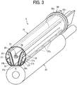
- FIG. 3 is a perspective view of the fixing device 5 with the vertical cross-sectional view of the fixing device 5.
- FIG. 4 is a vertical cross-sectional view of the fixing device 5 viewed from a front side of the fixing device 5.
- FIG. 5 is a perspective view of a belt holder to support a fixing belt.
- FIG. 6 is a perspective view of a variation of the belt holder.
- the fixing device 5 includes the fixing belt 21, the pressure roller 22, a halogen heater 23, a nip formation member 24, a stay 25, a reflector 26, guides 27, and temperature sensors 28.
- the fixing belt 21 is a cylindrical fixing member to fix an unfixed image (unfixed toner image) T to the sheet P and is disposed on an image bearing side of the sheet P on which the unfixed toner image T is borne.
- the fixing belt 21 in the present embodiment is an endless belt or film that includes a base layer formed on an inner side of the fixing belt 21 and made of a metal such as nickel and stainless steel (SUS) or a resin such as polyimide, and a release layer formed on the outer side of the fixing belt 21 and made of tetrafluoroethylene-perfluoroalkylvinylether copolymer (PFA), polytetrafluoroethylene (PTFE), or the like.
- SUS nickel and stainless steel
- PFA tetrafluoroethylene-perfluoroalkylvinylether copolymer
- PTFE polytetrafluoroethylene
- an elastic layer made of rubber such as silicone rubber, silicone rubber foam, or fluoro rubber may be interposed between the base layer and the release layer.
- the fixing belt 21 and the pressure roller 22 press the unfixed toner image T against the sheet P to fix the toner image onto the sheet P
- the elastic layer having a thickness of about 100 micrometers elastically deforms to absorb slight surface asperities of the fixing belt 21, thus preventing variation in gloss of the toner image on the sheet P.
- the fixing belt 21 is thin and has a small loop diameter to decrease the thermal capacity of the fixing belt 21.
- the base layer of the fixing belt 21 has a thickness of from 20 ⁇ m to 50 ⁇ m and the release layer has a thickness of from 10 ⁇ m to 50 ⁇ m.
- the fixing belt 21 has a total thickness not greater than 1 mm.
- the thickness of the elastic layer may be set to 100 to 300 ⁇ m.
- the fixing belt 21 may have the total thickness not greater than 0.20 mm and preferably not greater than 0.16 mm.
- the fixing belt 21 may have a loop diameter from 20 to 40 mm. Preferably, the loop diameter of the fixing belt 21 may not be greater than 30 mm.
- the pressure roller 22 is an opposed member opposed to an outer surface of the fixing belt 21.
- the pressure roller 22 includes a cored bar; an elastic layer coating the cored bar and being made of silicone rubber foam, fluoro rubber, or the like; and a release layer coating the elastic layer and being made of PFA, PTFE, or the like.
- the pressure roller 22 is a solid roller.
- the pressure roller 22 may be a hollow roller.
- a heating member such as a halogen heater may be disposed inside the pressure roller 22.
- the elastic layer of the pressure roller 22 may be made of solid rubber.
- the elastic layer of the pressure roller 22 is preferably made of sponge rubber to enhance thermal insulation of the pressure roller 22.
- Such a configuration reduces heat conduction from the fixing belt 21 to the pressure roller 22 and improves heating efficiency of the fixing belt 21.
- a driver disposed inside the image forming apparatus 1 drives and rotates the pressure roller 22 in a direction indicated by arrow A in FIG. 2 .
- the rotation of the pressure roller 22 drives the fixing belt 21 to rotate in a direction B in FIG. 2 due to frictional force therebetween.
- the sheet P bearing the unfixed toner image T is conveyed to a nip N between the fixing belt 21 and the pressure roller 22.
- the rotating fixing belt 21 and the rotating pressure roller 22 conveys the sheet P, and the sheet P passes through the nip N. Heat and pressure are applied to the sheet P to fix the unfixed toner image T onto the sheet P.
- the pressure roller 22 and the fixing belt 21 are configured to be able to approach and move away from each other. If the sheet is jammed in the nip N, separating the pressure roller 22 and the fixing belt 21 from each other and opening the nip N enables the jammed sheet to be removed.
- One of the pressure roller 22 and the fixing belt 21 may be configured to be fixed and the other may be configured to be movable so that the pressure roller 22 and the fixing belt 21 contact and separate each other.
- both the pressure roller 22 and the fixing belt 21 may be configured to move so that the pressure roller 22 and the fixing belt 21 contact and separate each other.
- the halogen heater 23 is a heating member disposed inside a loop of the fixing belt 21 and emitting infrared light, and radiant heat from the halogen heater 23 heats the fixing belt 21 and the nip formation member 24.
- a carbon heater, a ceramic heater or the like may be employed as the heating member.
- the nip formation member 24 and the pressure roller 22 sandwich the fixing belt 21 to form the nip N.
- the nip formation member 24 extends in a longitudinal direction thereof parallel to a width direction of the fixing belt 21 and has a planar nip formation portion 24a that is in contact with an inner circumferential surface of the fixing belt 21 and a pair of bent portions 24b that are bent from both end portions of the nip formation portion 24a in a belt rotation direction B to the opposite side to the pressure roller 22.
- a pressure member such as a spring presses the pressure roller 22 against the nip formation member 24, which causes the pressure roller 22 to contact the fixing belt 21 and forms the nip N therebetween.
- a nip formation surface 24c on the nip formation portion 24a in the fixing belt 21 side directly contacts the inner circumferential surface of the fixing belt 21. Therefore, when the fixing belt 21 rotates, the fixing belt 21 slides along the nip formation surface 24c.
- the nip formation surface 24c may be coated with an alumite treatment layer or a fluororesin material.
- a lubricant such as a fluorine-based grease may be applied to the nip formation surface 24c in order to ensure the slidability over time.
- the nip formation surface 24c is planar.
- the nip formation surface 24c may define a recess or other shapes.
- the nip formation surface 24c having a concave shape recessed to the side opposite to the pressure roller 22 leads the outlet of the sheet in the fixing nip N to be closer to the pressure roller 22, which improves separation of the sheet from the fixing belt 21.
- the nip formation member 24 is made of a material having a thermal conductivity larger than that of the stay 25.
- the material of the nip formation member 24 is preferably copper (thermal conductivity: 398 W / mk) or aluminum (thermal conductivity: 236 W / mk).
- the nip formation member 24 made of the material having such a large thermal conductivity absorbs the radiant heat from the halogen heater 23 and effectively transmits heat to the fixing belt 21.
- setting the thickness of the nip formation member 24 to 1 mm or less can shorten a heat transfer time in which the heat transfers from the nip formation member 24 to the fixing belt 21, which is advantageous in shortening a warm-up time of the fixing device 5.
- setting the thickness of the nip formation member 24 to be larger than 1 mm and 5 mm or less can improve a heat storage capacity of the nip formation member 24.
- the stay 25 is a support member to support the nip formation member 24 against the pressing force from the pressure roller 22.
- a pair of flat stays 25 are arranged on both sides of the halogen heater 23.
- each of the stays 25 is extended in a longitudinal shape across the width direction of the fixing belt 21 inside the loop of the fixing belt 21.
- the stays 25 contact both ends of the nip formation member 24 in the belt rotation direction B to support the nip formation member 24. Since the nip formation member 24 is supported by the respective stays 25, the bending of the nip formation member 24 in the pressing direction is restrained and the nip N having a uniform width across the longitudinal direction can be obtained.
- the stay 25 is preferably made of an iron-based metal such as stainless steel (SUS) or steel electrolytic cold commercial (SECC) that is electrogalvanized sheet steel to ensure rigidity.
- the thickness of the stay 25 is preferably 2 mm or less, more preferably 1.2 to 1.6 mm.
- the reflectors 26 are disposed facing the halogen heater 23 inside the loop of the fixing belt 21 to reflect radiant heat that is infrared light emitted from the halogen heater 23 to the nip formation member 24 and the inner circumferential surface of the fixing belt 21 above the nip formation member 24.
- a pair of reflectors 26 are arranged on both sides of the halogen heater 23 as in the case of the stays 25.
- Each reflector 26 has a reflecting portion 26a formed in a convex curved shape and a pair of bent portions 26b provided at both ends of the reflecting portion 26a.
- each reflector 26 is supported by the stay 25.
- the reflecting portion 26a is formed in a convex curved shape to protrude most at a position facing the halogen heater 23 or in the vicinity of the position. Accordingly, the infrared light applied to the reflecting portion 26a is reflected by the reflecting portion 26a and distributed upward and downward direction in FIG. 2 .
- the infrared light reflected upward passes through an upper opening formed between the stays 25 and between the reflectors 26 and is irradiated onto the fixing belt 21.
- the infrared light reflected downward passes through a lower opening formed between the stays 25 and between the reflectors 26 and is irradiated onto the nip formation member 24.
- the infrared light emitted from the halogen heater 23 passes through the upper opening and the lower opening between the stays 25 and between the reflectors 26 without being reflected by the reflecting portion 26a, and is directly irradiated onto the fixing belt 21 or the nip formation member 24.
- the infrared light emitted from the halogen heater 23 is reflected by the reflector 26 and irradiated to the fixing belt 21 or the nip formation member 24 or is directly irradiated to the fixing belt 21 or the nip formation member 24.
- the nip formation member 24 is effectively heated by the reflected light and the direct irradiation light.
- the infrared light is distributed upward and downward in FIG. 2 by the reflectors 26, so that the number of times of reflection of the infrared light between the reflectors 26 can be reduced, thus restraining a reduction in the thermal energy of the infrared light due to repeated reflection.
- Such a configuration can also restrain the reflectors 26 from being heated.
- the halogen heater 23 is continuously used for a long time, a decrease in reflectance due to the temperature rise and discoloration of the reflector 26 can be avoided, thus allowing high heating efficiency to be maintained.
- the reflector 26 Since the reflector 26 is interposed between the halogen heater 23 and the stay 25, the reflector 26 has a function of blocking the infrared light from the halogen heater 23 to the stay 25. The blocking function reduces wasteful energy use to heat the stay 25. Furthermore, in the present embodiment, since the reflecting portion 26a is formed in a convex curved shape, an air layer (gap) is interposed between the stay 25 and the reflecting portion 26a. The heat insulating effect of the air layer further reduces heat transfer to the stay 25.
- the surface of the reflector 26 facing the halogen heater 23 is treated with mirror finish or the like to increase reflectance.
- reflectance is measured using the spectrophotometer that is the ultraviolet visible infrared spectrophotometer UH4150 manufactured by Hitachi High-Technologies Corporation in which the incident angle is set 5°.
- the color temperature of the halogen heater varies depending on the application.
- the color temperature of the heater for the fixing device is about 2500 K.
- the reflectance of the reflector 26 is preferably 70% or more with wavelengths of high emission intensity in the halogen heater 23, that is, specifically the wavelengths of 900 to 1600 nm and more preferably 70% or more with the wavelengths of 1000 to 1300 nm.
- the stay 25 may have the function of reflection and thermal insulation of the reflector 26.
- performing the thermal insulation treatment or the mirror finishing on the inner surface of the stay 25 in the halogen heater 23 side enables the stay 25 to function as the reflector 26.
- Such a configuration can obviate the reflector 26 that is a separate component from the stay 25.
- the reflectance of the stay 25 subjected to the mirror finishing is preferably similar to the reflectance of the reflector 26.
- the guides 27 contacts the inner peripheral surface of the fixing belt 21 to guide the rotating fixing belt 21.
- the guides 27 are disposed on both the upstream side and the downstream side of the nip N in the belt rotational direction B.
- the guide 27 includes an attachment portion 27a fixed to the stay 25 and a curved guide portion 27b in contact with the inner peripheral surface of the fixing belt 21.
- the guide portion 27b includes a plurality of ribs 27c that are projections provided at equal distances in the belt width direction on a guide surface of the guide portion 27b that is the surface of the guide portion 27b in the fixing belt 21 side. Guiding the fixing belt 21 along the guide surface having the plurality of ribs 27c enables smooth rotation of the fixing belt 21 without large deformation of the fixing belt 21.
- the temperature sensors 28 are opposed to the outer surface of the fixing belt 21 to detect temperatures of the fixing belt 21.
- the temperature sensors 28 are disposed at two positions, the central position of the fixing belt 21 in the belt width direction, and one end position of the fixing belt 21 in the belt width direction.
- the temperature sensor 28 detects the temperature of the outer circumferential surface of the fixing belt 21, and output of the halogen heater 23 is controlled based on the detected temperatures so that the temperature of the fixing belt 21 becomes a desired temperature that is a fixing temperature.
- the temperature sensor 28 may be either contact type or non-contact type.
- the temperature sensor 28 may be a known temperature sensor type such as a thermopile, a thermostat, a thermistor, or a non-contact (NC) sensor.
- each cylindrical belt holder 30 is inserted in both lateral ends of the fixing belt 21.
- the belt holders 30 inserted into the both lateral ends of the fixing belt 21 support the fixing belt 21 in a state in which the fixing belt 21 is not basically applied with tension in a circumferential direction thereof while the fixing belt 21 does not rotate, that is, by a free belt system.
- the belt holder 30 includes a C-shaped supporter 30a inserted into the inner periphery of the fixing belt 21 to support the fixing belt 21 and a flange 30b that contacts an end surface of the fixing belt 21 to stop a movement of the fixing belt 21 in the width direction, that is, walking of the fixing belt 21 in the width direction.
- the supporter 30a may have a cylindrical shape which is continuous over its entire circumference.
- the belt holders 30 are fixed on a pair of side plates 31 that are frames of the fixing device 5.
- the belt holder 30 has an opening 30c as illustrated in FIG. 5 , and both ends of the halogen heater 23 and the stays 25 are supported by the side plates 31 through the openings 30c.
- the halogen heater 23 and the stays 25 may be supported by the belt holders 30.
- both the nip formation member 24 and the fixing belt 21 are heated by the infrared light directly emitted from the halogen heater 23 and the infrared light reflected by the reflectors 26.
- the heat generated by heating the nip formation member 24 and the fixing belt 21 is applied from both the nip formation member 24 and the fixing belt 20, so that the nip N can be efficiently heated.
- the fixing device 5 having such a configuration, as a measure for further enhancing the thermal efficiency, for example, it is conceivable to reduce the height of a structure such as the stay 25 or the reflector 26 (the height from the nip formation member 24) to widen the range (direct heating area) in which the fixing belt 21 is directly irradiated with infrared light.
- the height of the stay 25 is reduced, the rigidity of the stay 25 with respect to the pressing force from the pressure roller 22 would decrease. Accordingly, the nip formation member 24 would bend more, which might hamper the nip N from having a uniform width and a uniform pressure. Therefore, it does not mean that it is enough to simply reduce the heights of the stay 25 and the reflector 26.
- the fixing device 5 employs a configuration as described below in order to secure a wide direct heating area of the fixing belt 21 while securing the rigidity of the stay 25.
- the stays 25 are inclined relative to each other and the reflectors 26 are inclined relative to each other so that each of the distance between the stays 25 and the distance between the reflectors 26 gradually increases toward the opposite side (the upper side in FIG. 7 ) to the nip N side. That is, the distance between the opposing surfaces 250 of the stays 25 arranged on the upstream side and the downstream side from the halogen heater 23 in a sheet conveyance direction increases toward the opposite side to the nip N.
- a width ⁇ from the upper end surface 25b of one stay 25 of the stays 25 to the upper end surface 25b of the other stay 25 is set to be larger than a width ⁇ from the lower end surface 25a of the one stay 25 to the lower end surface 25a of the other stay 25 ( ⁇ ⁇ ⁇ ).
- the stays 25 are inclined relative to each other and the reflectors 26 are inclined relative to each other.
- Each of the distance between the stays 25 and the distance between the reflectors 26 increases toward the upper side in FIG. 7 .
- a width W1 of the upper opening between the stays 25 and between the reflectors 26 is larger than a width W3 of the upper opening in an example in which a pair of stays 25 are arranged in parallel to each other as illustrated in FIG. 26 (W1 > W3).
- Such a configuration can secure a wide range (direct heating area) in which the fixing belt 21 is directly irradiated with infrared light from the halogen heater 23, thus enhancing the thermal efficiency of the fixing belt 21.
- Increasing the direct heating area of the fixing belt 21 can also enhance the thermal responsiveness of the fixing belt 21 to lighting control (heating control) of the halogen heater 23.
- each of the distance between the stays 25 and the distance between the reflectors 26 increases toward the upper side in FIG. 7 . Accordingly, a width W2 of the lower opening in FIG. 7 between the stays 25 and between the reflectors 26 is smaller than a width W4 of the lower opening in the example illustrated in FIG. 26 (W2 ⁇ W4). Therefore, in the fixing device 5 according to the present embodiment, as illustrated in FIG. 7 , a width ⁇ of the nip formation member 24 in a sheet passing direction (recording medium passing direction) can be reduced.
- the width ⁇ of the nip formation member 24 in the sheet passing direction is a width from an upstream end to a downstream end of the nip formation member 24 in the sheet passing direction. Since the width ⁇ of the nip formation member 24 in the sheet passing direction can be reduced as described above, the nip formation member 24 is less likely to bend. Accordingly, the rigidity of the nip formation member 24 with respect to the pressing force from the pressure roller 22 increases, thus allowing the nip N to have a uniform width and pressure. The reduced width ⁇ of the nip formation member 24 in the sheet passing direction also allows downsizing of the fixing device 5.
- the lower end surface 25a of each stay 25 in FIG. 7 is arranged within a range smaller than the width ⁇ of the nip formation member 24 in the sheet passing direction. That is, in the cross section illustrated in FIG. 7 that intersects the width direction of the fixing belt 21, the width ⁇ from the lower end surface 25a of one stay 25 to the lower end surface 25a of the other stay 25 is set to be smaller than the width ⁇ of the nip formation member 24 in the sheet passing direction.
- the width ⁇ from one lower end surface 25a to the other lower end surface 25a, the width ⁇ from one upper end surface 25b to the other upper end surface 25b, and the width ⁇ of the nip formation member 24 in the sheet passing direction are set in a relationship of a ⁇ ⁇ ⁇ ⁇ . Note that the relationship is similarly established between the nip formation member 24 and each of the reflectors 26.
- each stay 25 extends linearly from the lower end surface 25a to the upper end surface 25b in FIG. 7 .
- Such a configuration can easily secure a height H1 of the stay 25 larger than a height H2 of a stay 25 having an L shape in cross section as illustrated in FIG. 27 (H1>H2). That is, in the example illustrated in FIG. 27 , since the stay 25 has the L shape in cross section, the width G2 of a contact portion of the stay 25 with the nip formation member 24 increases and the size of the nip formation member 24 in the horizontal direction of FIG. 27 also increases by an amount corresponding to the increase of the width G2.
- the fixing belt 21 has a circular shape slightly compressed in the vertical direction, thus hampering an increase in the height H2 of the stay 25 inside the loop of the fixing belt 21.
- the linear stays 25 are arranged to be inclined relative to each other, thus allowing a reduction in the width G1 at which the stay 25 contacts the nip formation member 24.
- the extension of the nip formation member 24 in the horizontal direction in FIG. 7 can be restrained, so that the height H1 of the stay 25 can be easily secured.
- the fixing device 5 adopts the layout in which the pair of linear-shaped stays 25 are arranged to be inclined relative to each other.
- Such a configuration can secure a large direct heating area of the fixing belt 21 while sufficiently securing the height H1 of the stays 25. That is, according to the present embodiment, effectively arranging the stays 25 in a limited space inside the loop of the fixing belt 21 can achieve both the enhancement of thermal efficiency and the securing of the rigidity of the stays 25.
- a fixing device can be provided that is small in size and excellent in fixing performance and energy saving.
- the contact width G1 at which the stay 25 contacts the nip formation member 24 can be reduced. Accordingly, the larger width W2 of the opening on the nip N side can be secured (W2 > W5). Thus, the direct heating area of the nip formation member 24 is widened, and the thermal efficiency is further enhanced.
- the stay 25 Since the stay 25 is linear, it is not necessary to perform the bending process on the stay 25, thus reducing the manufacturing cost. In the case of bending the stay 25, there is a limitation in the processing that the thickness of the stay 25 cannot be made too large (for example, it is difficult to secure a thickness of 3 mm or more). However, since it is not necessary to perform the bending process in the present embodiment, the thickness of the stay 25 can be increased and the rigidity can be enhanced.
- the liner shape of the stay 25 also allows the shape of the reflector 26 arranged along the stay 25 to be simplified.
- Such a configuration allows the fixing belt 21 or the nip formation member 24 to be irradiated with infrared light with a smaller number of reflections. Accordingly, the attenuation of the infrared light due to reflection can be restrained, thus enabling effective heating.
- the reflectors 26 are arranged to be inclined relative to each other, thus enhancing the heating efficiency (reflected light rate). That is, the reflectors 26 are not arranged in a direction parallel or perpendicular to the nip formation member 24 but is arranged so as to be inclined with respect to the nip formation member 24.
- Such a configuration can reduce the amount of infrared light reflected toward the halogen heater 23 and enhance the heating efficiency (reflected light rate).
- the shape of the stay 25 does not necessarily have to be linear.
- the pair of stays 25 may be formed to be slightly curved as long as the pair of stays 25 are inclined relative to each other so that the distance between the pair of stays 25 increases from the nip N side toward the opposite side.
- the stay 25 may have a curved shape following the curvature of the reflector 26.
- the stay 25 may have a shape in which a plurality of linear portions 251 and 252 having different angles are combined.
- each stay 25 in FIG. 7 is desirably arranged in parallel with the nip formation member 24 in order to stably support the nip formation member 24. That is, arranging the lower end surface 25a of each stay 25 in parallel with the nip formation member 24 increases the contact area between the stay 25 and the nip formation member 24, thus allowing the posture of the nip formation member 24 to be stabilized.
- each stay 25 is disposed perpendicular to the pressing direction E of the pressure roller 22 (see FIG. 7 ).
- the "pressing direction E of the pressure roller 22" used herein is a main direction of the pressing force that the nip formation member 24 receives from the pressure roller 22. For example, in a cross section illustrated in FIG.
- the pressing direction E is defined as a direction parallel to a straight line K passing through the center M of the nip N in the width direction (or the center of the fixing belt 21) and the center O of the pressure roller 22.
- each stay 25 is positioned by being inserted into hole portions 32 provided in the side plate 31.
- the pressing force of the pressure roller 22 acts on each of the stays 25 from the lower side in FIG. 10 to the upper side, the pressing force is mainly received by the upper surface 32a of the hole portion 32 in FIG. 10 . Therefore, it is desirable that the surface 32a of the hole portion 32 to receive the pressing force and the upper end surface 25b of the stay 25 in FIG. 10 to contact the hole portion 32 be disposed in parallel with each other.
- Such a configuration allows a large contact area to be ensured, and the stays 25 can be stably supported by the side plates 31.
- the surface 32a of the hole portion 32 to receive the pressing force and the upper end surface 25b of the stay 25 to contact the surface 32a are arranged perpendicular to the pressing direction E of the pressure roller 22.
- Such a configuration allows the pressing force of the pressure roller 22 to be reliably received by the side plate 31, thus restraining the deformation of the stay 25. If the upper end surface 25b of the stay 25 is arranged parallel to the nip formation member 24, the dimensions can be easily controlled.
- the nip formation member 24 can be stably supported. That is, since the distance between the support points of the stays 25 is wider on the downstream side than on the upstream side in the pressing direction E, the nip formation member 24 is stably supported without wobbling.
- the stay 25 is not limited to the shape where the stay 25 is continuously formed in the same cross-sectional shape over the entire longitudinal direction.
- the stay 25 may be formed in a shape having a step or a notch at one end in the longitudinal direction of the stay 25.
- the upper end surfaces 25b1 and 25b2 of the stays 25 having different heights with the step as a boundary are not necessarily parallel end surfaces with each other.
- An end surface (the upper end surface 25b2 having a greater height) other than the upper end surface 25b1 having a smaller height to be inserted into the hole portion 32 of the side plate 31 may be an end surface obtained by cutting a plate material.
- the configuration of positioning of the stay 25 is not limited to the configuration in which the stay 25 is inserted into the hole portion 32 of the side plate 31.
- the stay 25 may be inserted into and positioned by a hole provided in the belt holder 30 or the like.
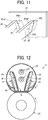
- FIG. 12 is a vertical sectional view of the fixing device according to a second embodiment of the present invention, viewed from a lateral side of the fixing device.
- only one halogen heater 23 is provided.
- two halogen heaters 23 are provided side by side in the vertical direction.
- the arrangement of the two halogen heaters 23 allows the heating range and application to be divided between the halogen heaters 23.
- one of the two halogen heaters 23 may be a heater for heating the central portion in the belt width direction and the other may be a heater for heating an end portion in the belt width direction, thus allowing the different heating ranges to be set.
- the upper halogen heater 23 in FIG. 12 may be mainly used to directly heat the fixing belt 21 and the lower halogen heater 23 may be mainly used to heat the nip formation member 24.
- FIG. 13 is a vertical sectional view of the fixing device according to a third embodiment of the present invention, viewed from a lateral side of the fixing device.
- the stay 25 and the reflector 26 are in direct contact with each other on the respective end sides of the stay 25 and the reflector 26.
- a low heat conducting member 33 having a lower heat conductivity than the stay 25 and the reflector 26 is interposed between the stay 25 and the reflector 26. That is, the stay 25 and the reflector 26 are in indirect contact with each other via the low heat conducting member 33.
- the stay 25 and the reflector 26 are in contact with each other via the low heat conducting member 33, heat transfer from the reflector 26 to the stay 25 can be restrained, thus further reducing the wasteful consumption of heat energy.
- FIG. 14 is a vertical sectional view of the fixing device according to a fourth embodiment of the present invention, viewed from a lateral side of the fixing device.
- the pair of stays 25 are arranged so as to be symmetrical with respect to a straight line U (see FIG. 7 ) passing through the center Q of the halogen heater 23 and the center O of the pressure roller 22.
- the pair of stays 25 are arranged non-linearly symmetric with each other. Specifically, in FIG. 14 , the left (nip exit side) stay 25 is arranged to be inclined with respect to the nip formation member 24, whereas the right (nip entrance side) stay 25 is arranged to be substantially orthogonal to the nip formation member 24. Further, in FIG.
- the right stay 25 has a length in the vertical direction (a length from the end surface 25a on the nip N side to the end surface 25b on the opposite side) shorter than a length of the left stay 25 in the vertical direction.
- the end surface used herein means an end surface in at least a region through which a sheet passes.
- the stays 25 are also arranged to be inclined relative to each other so that the distance between the stays 25 increases toward the upper side (the side opposite to the nip N) in FIG. 14 , thus allowing the same effect as the effect of the above-described embodiment to be obtained.
- FIG. 15 is a vertical sectional view of the fixing device according to a fifth embodiment of the present invention, viewed from a lateral side of the fixing device.
- through-holes 25c and 26c are provided in portions of each stay 25 and each reflector 26 close to the halogen heater 23 so that infrared light from the halogen heater 23 passes through the through-holes 25c and 26c and is directly applied to the fixing belt 21.
- the reflected light is applied to the halogen heater 23 without being applied to the fixing belt 21 and the nip formation member 24.
- the fixing belt 21 or the nip formation member 24 is irradiated with the infrared light having reflected a large number of times, so that the heat energy is attenuated, so that the heating efficiency is reduced.
- a part of the infrared light may not be effectively used as energy for heating the fixing belt 21 or the nip formation member 24.
- the through-holes 25c and 26c are provided in portions of each of the stays 25 and the reflectors 26 close to the halogen heater 23, respectively.
- the fixing belt 21 can be directly irradiated with the infrared light through the through-holes 25c and 26c, thus allowing enhancement of the thermal efficiency.
- the diameter (width) d1 of the through-hole 25c of the stay 25 is set to be larger than the diameter (width) d2 of the through-hole 26c of the reflector 26.
- the infrared light emitted from the halogen heater 23 is likely to spread as the distance from the halogen heater 23 increases. Accordingly, if the diameter d1 of the through-hole 25c of the stay 25 is equal to or smaller than the diameter d2 of the through-hole 26c of the reflector 26, a part of the infrared light that has passed through the through-hole 26c of the reflector 26 hits and blocked by an edge of the through-hole 25c of the stay 25. Therefore, as illustrated in FIG.
- the diameter d1 of the through-hole 25c of the stay 25 is set to be larger than the diameter d2 of the through-hole 26c of the reflector 26, thus preventing the infrared light from being applied to the edge of the through-hole 25c of the stay 25.
- the amount of infrared light directly applied to the fixing belt 21 can be increased and the wasteful consumption of heat energy to the stay 25 can be reduced.
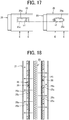
- the shapes of the through-holes 25c and 26c may be elliptical. In such a case, it is desirable that each of the through-holes 25c and 26c is formed to be longer in a direction intersecting the pressing direction E of the pressure roller 22. Such a configuration can secure the section modulus of the stay 25 and the reflector 26 in the pressing direction E and easily maintain the strength.
- the through-holes 25c and 26c may be rectangular.
- the opening widths of the rectangular through-holes 25c and 26c in the pressing direction E increase particularly at the longitudinal ends of the through-holes 25c and 26c (h1 > h2). Therefore, the elliptical shape is preferable to the rectangular shape in order to secure the opening widths to some extent and further secure the strength.
- FIG. 18 is a cross-sectional view of the stays 25, the reflectors 26, and the halogen heater 23 viewed from above or below in FIG. 15 .
- the through-holes 25c and 26c arranged on the opposite sides of the halogen heater 23 are provided at positions shifted from each other in the belt width direction (the vertical direction in FIG. 18 ).
- the right through-holes 25c and 26c and the left through-holes 25c and 26c are arranged in a staggered manner. Such an arrangement can prevent an area to be irradiated with infrared light through the through-hole 25c and 26c on the one side and an area to be irradiated with infrared light through the through-holes 25c and 26c on the other side from overlapping with each other in the belt width direction.
- an area of the fixing belt 21 that is not directly irradiated with the infrared light can be eliminated or reduced across the belt width direction.
- the fixing belt 21 can be substantially uniformly heated, thus preventing occurrence of fixing defects due to uneven temperature distribution on the fixing belt 21
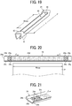
- FIG. 19 is a perspective view of a stay according to a sixth embodiment of the present invention.
- the above-described pair of stays 25 may be molded as a single stay 25.
- the stay 25 includes a pair of side walls 41 that are arranged to be inclined with respect to each other and bottom walls 42 that connect both ends of each side wall 41 in the longitudinal direction.
- the above-described stay 25 configured as one component can obviate separate positioning and assembly of the two stays 25, thus enhancing ease of assembling and maintenance.
- an opening 40 is formed between the bottom wall 42 on one end and the bottom wall 42 on the other end in the longitudinal direction.
- the fixing belt 21 is directly irradiated with infrared light from the halogen heater 23 through the opening 40.
- the width Y of the opening 40 is set to be larger than a maximum sheet conveyance span Wmax.
- maximum sheet conveyance span maximum recording medium conveyance span
- the "maximum sheet conveyance span (maximum recording medium conveyance span)" in the present specification refers to a width of an area through which a sheet (recording medium) ideally passes when the sheet is ideally conveyed without any displacement or skew of the sheet.
- FIGS. 20 to 22 are illustrations of the nip formation member 24 according to a seventh embodiment of the present invention.
- the nip formation member 24 has a plurality of inclined surfaces 24e on a light receiving surface 24d on the halogen heater side of the nip formation member 24 (nip formation portion 24a).
- the plurality of inclined surfaces 24e is inclined with respect to the light receiving surface 24d.
- Each inclined surface 24e is provided in a region outside the maximum sheet conveyance span Wmax on each end in the longitudinal direction of the nip formation member 24.
- Each inclined surface 24e is inclined so as to face the center side in the belt width direction (inclined in directions indicated by arrow J in FIGS. 20 and 21 ).
- the inclined surfaces 24e inclined to face the center side of the fixing belt 21 in the belt width direction reflect the infrared light R emitted from the halogen heater 23 toward the center side of the fixing belt 21 in the belt width direction. Then, the reflected light is further reflected by the reflector 26 and is applied to an area inside the maximum sheet conveyance span Wmax.
- a part of the infrared light (radiant heat) emitted to the outside of the maximum sheet conveyance span Wmax is reflected by the inclined surfaces 24e and can be used as heat energy for heating the area inside the maximum sheet conveyance span Wmax, thus enhancing the heat energy efficiency.
- the halogen heater 23 irradiates the area outside the maximum sheet conveyance span Wmax with a large amount of infrared light.
- the inclined surfaces 24e reflect a part of the infrared light toward the center side of the nip formation member 24 in the belt width direction.
- the part of the infrared light is effectively used as the thermal energy to heat the area inside the maximum sheet conveyance span Wmax in the nip formation member 24. As a result, the thermal energy efficiency can be enhanced.
- the reflection of the infrared light by the inclined surfaces 24e reduces the heat absorbed by the area outside the sheet conveyance span Wmax in the nip formation member 24.
- Such a configuration can restrain an excessive rise in temperature outside the maximum sheet conveyance span Wmax during continuous sheet passing, thus reducing the risk of failure of the fixing device.
- Such a configuration can obviate measures such as lowering the printing speed when the temperature rises, thus allowing enhancement of productivity (fixing speed).
- the light receiving surface 24d inside the maximum sheet conveyance span Wmax of the nip formation member 24 is coated with black, thus enhancing the heat absorption rate inside the maximum paper conveyance span Wmax.
- the light receiving surface 24d and the inclined surface 24e are not coated with black, and the reflectance is increased.
- coating fine particles that may be a black paint by using a coating method such as spray may set surface roughness of the area inside the maximum sheet conveyance span Wmax on the light receiving surface 24d of the nip formation member 24 to be larger than surface roughness of the area outside the maximum sheet conveyance span Wmax on the light receiving surface 24d of the nip formation member 24.
- Coating fine particles also improves the thermal energy efficiency because the heat absorptivity of the area inside the maximum sheet conveyance span Wmax, on the light receiving surface 24d becomes larger than the heat absorptivity of the area outside the maximum sheet conveyance span Wmax on the light receiving surface 24d.
- the surface roughness Ra of the light receiving surface 24d inside the maximum sheet conveyance span Wmax is preferably 0.5 or more.
- the inclined surfaces 24e may be configured separately from the nip formation member 24, making the inclined surfaces 24e and the nip formation member 24 as one component is preferable from the viewpoint of manufacturing cost.
- the inclined surfaces 24e are formed as a single component by a drawing process using a press.
- the depth Z of the drawing (the height of the inclined surface 24e illustrated in FIG. 22 ) be about 0.5 mm to 2 mm.
- Changing a length L of the drawing process which is a length of the inclined surface 24e illustrated in FIG. 22 in the belt width direction, under the constant depth Z of drawing process allows appropriately adjusting the inclination angle ⁇ of the inclined surface 24e.
- the inclination angle ⁇ 1 of the inclined surface 24e on the outer side (left side in FIG. 23 ) in the belt width direction is set to be larger than the inclination angle ⁇ 2 of the inclined surface 24e on the inner side (right side in FIG. 23 ). Accordingly, the reflection angle of the inclined surface 24e on the outer side in the belt width direction can be increased, so that the infrared light R on the outer side is more likely to be reflected to the area inside the maximum sheet conveyance span Wmax.
- recesses 24f are formed on a back side of the surface (nip formation surface 24c) on which the inclined surfaces 24e are formed.
- a lubricant such as grease may be stored in the recesses 24f thus formed.
- the lubricant since the lubricant is held in the recesses 24f, the lubricant can be interposed between the nip formation member 24 and the fixing belt 21 for a long time, thus allowing extension of the product lives and maintenance cycles of the nip formation member 24 and the fixing belt 21.
- the longitudinal direction of the recess 24f may be inclined toward the downstream side in the belt rotation direction B so that a portion of the recesses 24f downstream side is toward the central portion of the nip formation member 24 in the belt width direction.
- the lubricant stored in the recesses 24f move in directions indicated by arrows D in FIG. 24 along the longitudinal direction of the recesses 24f, thus allowing the lubricant to be actively supplied to the center side in the belt width direction.
- the lubricant can be interposed between the nip formation member 24 and the fixing belt 21 for a long time.
- a shape between inclined surfaces 24e next to each other is preferably a flat surface 24g and not the inclined surface 24e.
- a flat surface 24h is also formed between the recesses 24f on the back side of the inclined surfaces 24e (see FIG. 22 ), thus allowing the fixing belt 21 to be supported by the flat surface 24h.
- Such a configuration can refrain the deformation of the fixing belt 21 at the portions at which the recesses 24f are provided, thus preventing the fixing belt 21 from being damaged such as buckling breakage (kinking).
- Embodiments of the present invention are not limited to the above-described embodiments and various modifications and improvements are possible.
- the pair of stays 25 are disposed on both sides of the halogen heater 23.
- the halogen heater 23 may be disposed at a position protruding upward in FIG. 7 . That is, according to an embodiment of the present invention, if the pair of stays 25 are disposed on both sides of a straight line U (see FIG. 7 ) passing through the center Q of the halogen heater 23 and the center O of the pressure roller 22, a configuration may be employed in which the halogen heater 23 may not be interposed between the pair of stays 25.
- the present invention is also applicable to a fixing device that does not include the reflectors 26.
- two structural bodies of a structure may be arranged to be inclined with respect to each other so as to increase the distance from the nip side toward the opposite side of the nip side.
- the two structural bodies may be both the pair of stays 25 and the pair of reflectors 26, one pair of the pair of stays 25 and the pair of reflectors 26, or other members than the pair of stays 25 and the pair of reflectors 26.
- the fixing device is not limited to the fixing device 5 that conveys a sheet in the horizontal direction as illustrated in FIG. 1 .
- the location and orientation of the fixing device 5 may be appropriately changed.
- the present invention may be applicable to the fixing device 5 as illustrated in FIG. 25 that conveys a sheet in the vertical direction.
Landscapes
- Physics & Mathematics (AREA)
- General Physics & Mathematics (AREA)
- Fixing For Electrophotography (AREA)
Abstract
A fixing device (5) includes a fixing member (21) in a cylindrical form, an opposed member opposed to an outer surface of the fixing member, a heating member inside a loop of the fixing member, a nip formation member inside the loop of the fixing member to form a nip with the opposed member with the fixing member interposed between the opposed member and the nip formation member, and a structure including opposing surfaces (250, 260) upstream and downstream from the heating member in a recording-medium conveyance direction inside the loop of the fixing member in a cross section intersecting a width direction of the fixing member. A distance between the opposing surfaces in the cross section increases from a nip side of the structure facing the nip to an opposite side of the structure opposite the nip side.
Description
- Aspects of the present invention relate to a fixing device and an image forming apparatus including the fixing device.
- An electrophotographic image forming apparatus such as a copier and a printer includes a fixing device to convey a recording medium such as a sheet on which an unfixed image is formed to a nip formed between members such as rollers or belts opposed to each other, heat the recording medium, and fix the unfixed image on the recording medium.
- For example,
JP-2009-093141-A - To enhance the thermal efficiency of a fixing device to improve the fixing performance and reduce the energy consumption, it is desirable to secure a wide range in which the heat generated from a heating member can be directly applied to a fixing member such as the belt unit.
- However, in a configuration in which, in addition to the heating member, various structures such as a nip formation member and a support member supporting the nip formation member are arranged inside the cylindrical fixing member, heat from the heating member is blocked by surrounding structures. Accordingly, the range in which the heat from the heating member can be directly applied to the fixing member is limited. In particular, in a small-sized fixing device using a fixing member having a small diameter, the gap between the heating member and a structure around the heating member is narrow. Such a configuration further makes it difficult to secure the range in which the heat from the heating member can be directly applied to the fixing member.
- In an aspect of the present disclosure, there is provided a fixing device includes a fixing member, an opposed member, a heating member, a nip formation member, and a structure. The fixing member is in a cylindrical form. The opposed member is opposed to an outer surface of the fixing member. The heating member is inside a loop of the fixing member. The nip formation member is inside the loop of the fixing member to form a nip with the opposed member with the fixing member interposed between the opposed member and the nip formation member. The structure includes opposing surfaces upstream and downstream from the heating member in a recording-medium conveyance direction inside the loop of the fixing member in a cross section intersecting a width direction of the fixing member. A distance between the opposing surfaces in the cross section increases from a nip side of the structure facing the nip to an opposite side of the structure opposite the nip side.
- In another aspect of the present disclosure, there is provided an image forming apparatus that includes an image forming device and the fixing device. The image forming device is forms an image on a recording medium. The fixing device fixes the image formed by the image forming device on the recording medium.
- According to the present invention, the distance between opposing surfaces of a structure inside a fixing member increases from a nip side to the opposite side of the nip side. Such a configuration can efficiently heat the fixing member, thus enhancing the thermal efficiency.
- A more complete appreciation of the disclosure and many of the attendant advantages and features thereof can be readily obtained and understood from the following detailed description with reference to the accompanying drawings, wherein:
-
FIG. 1 is a schematic view of a configuration of an image forming apparatus according to a first embodiment of the present invention; -
FIG. 2 is a cross-sectional side view of a fixing device according to an embodiment of the present invention; -
FIG. 3 is a perspective view of the fixing device with a vertical cross-sectional view of the fixing device; -
FIG. 4 is a vertical cross-sectional view of the fixing device viewed from a front side of the fixing device; -
FIG. 5 is a perspective view of a belt holder; -
FIG. 6 is a perspective view of a variation of the belt holder; -
FIG. 7 is a cross-sectional side view of a fixing device according to an embodiment of the present invention; -
FIG. 8 is a cross-sectional view of a stay according to a variation; -
FIG. 9 is a cross-sectional view of another variation of the stay; -
FIG. 10 is a perspective view of a structure of an end of the stay supported by a side plate; -
FIG. 11 is a perspective view of a variation of the stay; -
FIG. 12 is a vertical cross-sectional view of the fixing device according to a second embodiment of the present invention viewed from a lateral side of the fixing device; -
FIG. 13 is a vertical cross-sectional view of the fixing device according to a third embodiment of the present invention viewed from a lateral side of the fixing device; -
FIG. 14 is a vertical cross-sectional view of the fixing device according to a fourth embodiment of the present invention viewed from a lateral side of the fixing device; -
FIG. 15 is a vertical cross-sectional view of the fixing device according to a fifth embodiment of the present invention viewed from a lateral side of the fixing device; -
FIG. 16 is a perspective view of an example in which through-holes are formed in an elliptical shape; -
FIG. 17 is a comparative diagram comparing a rectangular through-hole with the elliptical through-hole; -
FIG. 18 is a cross-sectional view of reflectors, stays, and a halogen heater as viewed from above or below inFIG. 15 ; -
FIG. 19 is a perspective view of the stay according to a sixth embodiment of the present invention; -
FIG. 20 is a plan view of a nip formation member according to a seventh embodiment of the present invention; -
FIG. 21 is a perspective view of an end of the nip formation member according to the seventh embodiment of the present invention; -
FIG. 22 is a cross sectional view illustrating an operation of the nip formation member according to the seventh embodiment of the present invention; -
FIG. 23 is a cross sectional view illustrating an example of inclined surfaces having different inclination angles; -
FIG. 24 is a plan view of an example in which recesses are inclined with respect to a belt rotation direction; -
FIG. 25 is a schematic view of an example of a configuration of the image forming apparatus including a fixing device to convey a sheet in a vertical direction; -
FIG. 26 is a cross-sectional side view of a fixing device according to a first comparative example; and -
FIG. 27 is a cross-sectional side view of a fixing device according to a second comparative example. - The accompanying drawings are intended to depict embodiments of the present disclosure and should not be interpreted to limit the scope thereof. The accompanying drawings are not to be considered as drawn to scale unless explicitly noted.
- The terminology used herein is for the purpose of describing particular embodiments only and is not intended to be limiting of the present disclosure. As used herein, the singular forms "a", "an" and "the" are intended to include the plural forms as well, unless the context clearly indicates otherwise.
- In describing embodiments illustrated in the drawings, specific terminology is employed for the sake of clarity. However, the disclosure of this specification is not intended to be limited to the specific terminology so selected and it is to be understood that each specific element includes all technical equivalents that have a similar function, operate in a similar manner, and achieve a similar result.
- With reference to drawings attached, a description is given below of the present invention. In the drawings for illustrating embodiments of the present invention, identical reference numerals are assigned to elements such as members and parts that have an identical function or an identical shape as long as differentiation is possible and descriptions of such elements may be omitted once the description is provided.
-
FIG. 1 is a schematic view of a configuration of an image forming apparatus according to an embodiment of the present invention. Referring toFIG. 1 , a configuration and operation of the image forming apparatus according to the present embodiment are described below. - An
image forming apparatus 1 illustrated inFIG. 1 is illustrated as a monochrome electrophotographic laser printer. Note that the image forming apparatus according to an embodiment of the present invention may be a printer, a copier, a facsimile machine, a multifunction peripheral (MFP) having at least two of copying, printing, scanning, facsimile, and plotter functions. The image forming apparatus is not limited to a monochrome image forming apparatus and may be a color image forming apparatus. - As illustrated in
FIG. 1 , theimage forming apparatus 1 according to the present embodiment includes animage forming device 2 to form an image, a recordingmedium feeding device 3 to feed a sheet P as a recording medium, a transfer device 4 to transfer the image onto the fed sheet P, a fixingdevice 5 to fix the image transferred onto the sheet P, and asheet ejection device 6 to eject the sheet P with the fixed image to an outside of theimage forming apparatus 1. - The
image forming device 2 includes a drum-shapedphotoconductor 7, a chargingroller 8 as a charging device to charge a surface of thephotoconductor 7, anexposure device 9 as a latent image forming device that exposes the surface of thephotoconductor 7 to form an electrostatic latent image on thephotoconductor 7, a developingroller 10 as a developing device that supplies toner as a developer to the surface of thephotoconductor 7 to visualize the electrostatic latent image, and acleaning blade 11 as a cleaner to clean the surface of thephotoconductor 7. - As the start of image forming operation is instructed, in the
image forming device 2, thephotoconductor 7 starts rotating, and the chargingroller 8 uniformly charges the surface of thephotoconductor 7 to a high potential. Next, based on image data of a document read by a scanner or print data transmitted by a terminal device, theexposure device 9 exposes the surface of thephotoconductor 7. Then, the potential of an exposed surface drops, and the electrostatic latent image is formed on thephotoconductor 7. The developingroller 10 supplies toner to the electrostatic latent image, thereby developing the latent image into a toner image on thephotoconductors 7. - The toner image formed on the
photoconductor 7 is transferred onto the sheet P in a transfer nip between thephotoconductor 7 and atransfer roller 15 disposed in the transfer device 4. The sheet P is fed from the recordingmedium feeding device 3. In the recordingmedium feeding device 3, asheet feeding roller 13 feeds the sheet P from asheet tray 12 to a feeding path one by one. Atiming roller pair 14 sends out the sheet P fed from thesheet tray 12 to a transfer nip, timed to coincide with the toner image on thephotoconductor 7. The toner image on thephotoconductor 7 is transferred onto the sheet P in the transfer nip. After the toner image is transferred from thephotoconductors 7 onto the sheet P, thecleaning blade 11 removes residual toner on thephotoconductor 7. - The sheet P bearing the toner image is conveyed to the
fixing device 5. In thefixing device 5, heat and pressure when the sheet P passes through between a fixingbelt 21 and apressure roller 22 fixes the toner image onto the sheet P. Subsequently, the sheet P is conveyed to thesheet ejection device 6, and anejection roller pair 16 ejects the sheet P outside theimage forming apparatus 1. Then, a series of print operations completes. - With reference to
FIGS. 2 to 6 , a detailed description is provided of a configuration of the fixingdevice 5 according to a first embodiment of the present invention. -
FIG. 2 is a vertical cross-sectional view of the fixingdevice 5 viewed from a lateral side of the fixingdevice 5.FIG. 3 is a perspective view of the fixingdevice 5 with the vertical cross-sectional view of the fixingdevice 5.FIG. 4 is a vertical cross-sectional view of the fixingdevice 5 viewed from a front side of the fixingdevice 5.FIG. 5 is a perspective view of a belt holder to support a fixing belt.FIG. 6 is a perspective view of a variation of the belt holder. - As illustrated in
FIG. 2 , the fixingdevice 5 includes the fixingbelt 21, thepressure roller 22, ahalogen heater 23, anip formation member 24, astay 25, areflector 26, guides 27, andtemperature sensors 28. - The fixing
belt 21 is a cylindrical fixing member to fix an unfixed image (unfixed toner image) T to the sheet P and is disposed on an image bearing side of the sheet P on which the unfixed toner image T is borne. The fixingbelt 21 in the present embodiment is an endless belt or film that includes a base layer formed on an inner side of the fixingbelt 21 and made of a metal such as nickel and stainless steel (SUS) or a resin such as polyimide, and a release layer formed on the outer side of the fixingbelt 21 and made of tetrafluoroethylene-perfluoroalkylvinylether copolymer (PFA), polytetrafluoroethylene (PTFE), or the like. Optionally, an elastic layer made of rubber such as silicone rubber, silicone rubber foam, or fluoro rubber may be interposed between the base layer and the release layer. While the fixingbelt 21 and thepressure roller 22 press the unfixed toner image T against the sheet P to fix the toner image onto the sheet P, the elastic layer having a thickness of about 100 micrometers elastically deforms to absorb slight surface asperities of the fixingbelt 21, thus preventing variation in gloss of the toner image on the sheet P. Additionally, in the present embodiment, the fixingbelt 21 is thin and has a small loop diameter to decrease the thermal capacity of the fixingbelt 21. For example, the base layer of the fixingbelt 21 has a thickness of from 20 µm to 50 µm and the release layer has a thickness of from 10 µm to 50 µm. Thus, the fixingbelt 21 has a total thickness not greater than 1 mm. In addition, when the fixingbelt 21 includes the elastic layer, the thickness of the elastic layer may be set to 100 to 300 µm. In order to further decrease the thermal capacity of the fixingbelt 21, the fixingbelt 21 may have the total thickness not greater than 0.20 mm and preferably not greater than 0.16 mm. In the present embodiment, the fixingbelt 21 may have a loop diameter from 20 to 40 mm. Preferably, the loop diameter of the fixingbelt 21 may not be greater than 30 mm. - The
pressure roller 22 is an opposed member opposed to an outer surface of the fixingbelt 21. Thepressure roller 22 includes a cored bar; an elastic layer coating the cored bar and being made of silicone rubber foam, fluoro rubber, or the like; and a release layer coating the elastic layer and being made of PFA, PTFE, or the like. According to the present embodiment, thepressure roller 22 is a solid roller. Alternatively, thepressure roller 22 may be a hollow roller. When thepressure roller 22 is the hollow roller, a heating member such as a halogen heater may be disposed inside thepressure roller 22. The elastic layer of thepressure roller 22 may be made of solid rubber. Alternatively, if no heating member is disposed inside thepressure roller 22, the elastic layer of thepressure roller 22 is preferably made of sponge rubber to enhance thermal insulation of thepressure roller 22. Such a configuration reduces heat conduction from the fixingbelt 21 to thepressure roller 22 and improves heating efficiency of the fixingbelt 21. - A driver disposed inside the
image forming apparatus 1 drives and rotates thepressure roller 22 in a direction indicated by arrow A inFIG. 2 . The rotation of thepressure roller 22 drives the fixingbelt 21 to rotate in a direction B inFIG. 2 due to frictional force therebetween. After the toner image is transferred onto the sheet P, the sheet P bearing the unfixed toner image T is conveyed to a nip N between the fixingbelt 21 and thepressure roller 22. Therotating fixing belt 21 and therotating pressure roller 22 conveys the sheet P, and the sheet P passes through the nip N. Heat and pressure are applied to the sheet P to fix the unfixed toner image T onto the sheet P. - The
pressure roller 22 and the fixingbelt 21 are configured to be able to approach and move away from each other. If the sheet is jammed in the nip N, separating thepressure roller 22 and the fixingbelt 21 from each other and opening the nip N enables the jammed sheet to be removed. One of thepressure roller 22 and the fixingbelt 21 may be configured to be fixed and the other may be configured to be movable so that thepressure roller 22 and the fixingbelt 21 contact and separate each other. Alternatively, both thepressure roller 22 and the fixingbelt 21 may be configured to move so that thepressure roller 22 and the fixingbelt 21 contact and separate each other. - The
halogen heater 23 is a heating member disposed inside a loop of the fixingbelt 21 and emitting infrared light, and radiant heat from thehalogen heater 23 heats the fixingbelt 21 and thenip formation member 24. Alternatively, instead of thehalogen heater 23, a carbon heater, a ceramic heater or the like may be employed as the heating member. - The
nip formation member 24 and thepressure roller 22 sandwich the fixingbelt 21 to form the nip N. Specifically, thenip formation member 24 extends in a longitudinal direction thereof parallel to a width direction of the fixingbelt 21 and has a planar nipformation portion 24a that is in contact with an inner circumferential surface of the fixingbelt 21 and a pair ofbent portions 24b that are bent from both end portions of thenip formation portion 24a in a belt rotation direction B to the opposite side to thepressure roller 22. A pressure member such as a spring presses thepressure roller 22 against thenip formation member 24, which causes thepressure roller 22 to contact the fixingbelt 21 and forms the nip N therebetween. - A
nip formation surface 24c on thenip formation portion 24a in the fixingbelt 21 side directly contacts the inner circumferential surface of the fixingbelt 21. Therefore, when the fixingbelt 21 rotates, the fixingbelt 21 slides along thenip formation surface 24c. In order to improve the abrasion resistance and the slidability of thenip formation surface 24c, thenip formation surface 24c may be coated with an alumite treatment layer or a fluororesin material. Furthermore, a lubricant such as a fluorine-based grease may be applied to thenip formation surface 24c in order to ensure the slidability over time. In the present embodiment, thenip formation surface 24c is planar. Alternatively, thenip formation surface 24c may define a recess or other shapes. For example, thenip formation surface 24c having a concave shape recessed to the side opposite to thepressure roller 22 leads the outlet of the sheet in the fixing nip N to be closer to thepressure roller 22, which improves separation of the sheet from the fixingbelt 21. - The
nip formation member 24 is made of a material having a thermal conductivity larger than that of thestay 25. For example, the material of thenip formation member 24 is preferably copper (thermal conductivity: 398 W / mk) or aluminum (thermal conductivity: 236 W / mk). Thenip formation member 24 made of the material having such a large thermal conductivity absorbs the radiant heat from thehalogen heater 23 and effectively transmits heat to the fixingbelt 21. For example, setting the thickness of thenip formation member 24 to 1 mm or less can shorten a heat transfer time in which the heat transfers from thenip formation member 24 to the fixingbelt 21, which is advantageous in shortening a warm-up time of the fixingdevice 5. In contrast, setting the thickness of thenip formation member 24 to be larger than 1 mm and 5 mm or less can improve a heat storage capacity of thenip formation member 24. - The
stay 25 is a support member to support thenip formation member 24 against the pressing force from thepressure roller 22. In the present embodiment, a pair offlat stays 25 are arranged on both sides of thehalogen heater 23. Like thenip formation member 24, each of thestays 25 is extended in a longitudinal shape across the width direction of the fixingbelt 21 inside the loop of the fixingbelt 21. The stays 25 contact both ends of thenip formation member 24 in the belt rotation direction B to support thenip formation member 24. Since thenip formation member 24 is supported by the respective stays 25, the bending of thenip formation member 24 in the pressing direction is restrained and the nip N having a uniform width across the longitudinal direction can be obtained. Thestay 25 is preferably made of an iron-based metal such as stainless steel (SUS) or steel electrolytic cold commercial (SECC) that is electrogalvanized sheet steel to ensure rigidity. The thickness of thestay 25 is preferably 2 mm or less, more preferably 1.2 to 1.6 mm. - The
reflectors 26 are disposed facing thehalogen heater 23 inside the loop of the fixingbelt 21 to reflect radiant heat that is infrared light emitted from thehalogen heater 23 to the nipformation member 24 and the inner circumferential surface of the fixingbelt 21 above thenip formation member 24. In the present embodiment, a pair ofreflectors 26 are arranged on both sides of thehalogen heater 23 as in the case of the stays 25. Eachreflector 26 has a reflectingportion 26a formed in a convex curved shape and a pair ofbent portions 26b provided at both ends of the reflectingportion 26a. One of thebent portions 26b is engaged with anend surface 25a on the nip N side of thestay 25 and the other of thebent portions 26b is engaged with anend surface 25b on the opposite side of thestay 25 which is opposite the nip N side. Thus, eachreflector 26 is supported by thestay 25. - The reflecting
portion 26a is formed in a convex curved shape to protrude most at a position facing thehalogen heater 23 or in the vicinity of the position. Accordingly, the infrared light applied to the reflectingportion 26a is reflected by the reflectingportion 26a and distributed upward and downward direction inFIG. 2 . The infrared light reflected upward passes through an upper opening formed between thestays 25 and between thereflectors 26 and is irradiated onto the fixingbelt 21. On the other hand, the infrared light reflected downward passes through a lower opening formed between thestays 25 and between thereflectors 26 and is irradiated onto thenip formation member 24. Apart of the infrared light emitted from thehalogen heater 23 passes through the upper opening and the lower opening between thestays 25 and between thereflectors 26 without being reflected by the reflectingportion 26a, and is directly irradiated onto the fixingbelt 21 or thenip formation member 24. As described above, the infrared light emitted from thehalogen heater 23 is reflected by thereflector 26 and irradiated to the fixingbelt 21 or thenip formation member 24 or is directly irradiated to the fixingbelt 21 or thenip formation member 24. Thus, thenip formation member 24 is effectively heated by the reflected light and the direct irradiation light. - Further, the infrared light is distributed upward and downward in
FIG. 2 by thereflectors 26, so that the number of times of reflection of the infrared light between thereflectors 26 can be reduced, thus restraining a reduction in the thermal energy of the infrared light due to repeated reflection. Such a configuration can also restrain thereflectors 26 from being heated. Thus, even if thehalogen heater 23 is continuously used for a long time, a decrease in reflectance due to the temperature rise and discoloration of thereflector 26 can be avoided, thus allowing high heating efficiency to be maintained. - Since the
reflector 26 is interposed between thehalogen heater 23 and thestay 25, thereflector 26 has a function of blocking the infrared light from thehalogen heater 23 to thestay 25. The blocking function reduces wasteful energy use to heat thestay 25. Furthermore, in the present embodiment, since the reflectingportion 26a is formed in a convex curved shape, an air layer (gap) is interposed between thestay 25 and the reflectingportion 26a. The heat insulating effect of the air layer further reduces heat transfer to thestay 25. - The surface of the
reflector 26 facing thehalogen heater 23 is treated with mirror finish or the like to increase reflectance. In the present embodiment, reflectance is measured using the spectrophotometer that is the ultraviolet visible infrared spectrophotometer UH4150 manufactured by Hitachi High-Technologies Corporation in which the incident angle is set 5°. In general, the color temperature of the halogen heater varies depending on the application. The color temperature of the heater for the fixing device is about 2500 K. The reflectance of thereflector 26 is preferably 70% or more with wavelengths of high emission intensity in thehalogen heater 23, that is, specifically the wavelengths of 900 to 1600 nm and more preferably 70% or more with the wavelengths of 1000 to 1300 nm. - Alternatively, the
stay 25 may have the function of reflection and thermal insulation of thereflector 26. For example, performing the thermal insulation treatment or the mirror finishing on the inner surface of thestay 25 in thehalogen heater 23 side enables thestay 25 to function as thereflector 26. Such a configuration can obviate thereflector 26 that is a separate component from thestay 25. The reflectance of thestay 25 subjected to the mirror finishing is preferably similar to the reflectance of thereflector 26. - The
guides 27 contacts the inner peripheral surface of the fixingbelt 21 to guide therotating fixing belt 21. In the present embodiment, theguides 27 are disposed on both the upstream side and the downstream side of the nip N in the belt rotational direction B. Theguide 27 includes anattachment portion 27a fixed to thestay 25 and acurved guide portion 27b in contact with the inner peripheral surface of the fixingbelt 21. As illustrated inFIG. 3 , theguide portion 27b includes a plurality ofribs 27c that are projections provided at equal distances in the belt width direction on a guide surface of theguide portion 27b that is the surface of theguide portion 27b in the fixingbelt 21 side. Guiding the fixingbelt 21 along the guide surface having the plurality ofribs 27c enables smooth rotation of the fixingbelt 21 without large deformation of the fixingbelt 21. - The
temperature sensors 28 are opposed to the outer surface of the fixingbelt 21 to detect temperatures of the fixingbelt 21. In the present embodiment, thetemperature sensors 28 are disposed at two positions, the central position of the fixingbelt 21 in the belt width direction, and one end position of the fixingbelt 21 in the belt width direction. Thetemperature sensor 28 detects the temperature of the outer circumferential surface of the fixingbelt 21, and output of thehalogen heater 23 is controlled based on the detected temperatures so that the temperature of the fixingbelt 21 becomes a desired temperature that is a fixing temperature. Thetemperature sensor 28 may be either contact type or non-contact type. Thetemperature sensor 28 may be a known temperature sensor type such as a thermopile, a thermostat, a thermistor, or a non-contact (NC) sensor. - As illustrated in
FIG. 4 , eachcylindrical belt holder 30 is inserted in both lateral ends of the fixingbelt 21. As described above, thebelt holders 30 inserted into the both lateral ends of the fixingbelt 21 support the fixingbelt 21 in a state in which the fixingbelt 21 is not basically applied with tension in a circumferential direction thereof while the fixingbelt 21 does not rotate, that is, by a free belt system. - As illustrated in
FIGS. 3 to 5 , thebelt holder 30 includes a C-shapedsupporter 30a inserted into the inner periphery of the fixingbelt 21 to support the fixingbelt 21 and aflange 30b that contacts an end surface of the fixingbelt 21 to stop a movement of the fixingbelt 21 in the width direction, that is, walking of the fixingbelt 21 in the width direction. As illustrated inFIG. 6 , thesupporter 30a may have a cylindrical shape which is continuous over its entire circumference. As illustrated inFIG. 4 , thebelt holders 30 are fixed on a pair ofside plates 31 that are frames of the fixingdevice 5. Thebelt holder 30 has anopening 30c as illustrated inFIG. 5 , and both ends of thehalogen heater 23 and thestays 25 are supported by theside plates 31 through theopenings 30c. Thehalogen heater 23 and thestays 25 may be supported by thebelt holders 30. - As described above, in the present embodiment, both the
nip formation member 24 and the fixingbelt 21 are heated by the infrared light directly emitted from thehalogen heater 23 and the infrared light reflected by thereflectors 26. As a result, in the nip N, the heat generated by heating thenip formation member 24 and the fixingbelt 21 is applied from both thenip formation member 24 and the fixing belt 20, so that the nip N can be efficiently heated. - In the
fixing device 5 having such a configuration, as a measure for further enhancing the thermal efficiency, for example, it is conceivable to reduce the height of a structure such as thestay 25 or the reflector 26 (the height from the nip formation member 24) to widen the range (direct heating area) in which the fixingbelt 21 is directly irradiated with infrared light. However, when the height of thestay 25 is reduced, the rigidity of thestay 25 with respect to the pressing force from thepressure roller 22 would decrease. Accordingly, thenip formation member 24 would bend more, which might hamper the nip N from having a uniform width and a uniform pressure. Therefore, it does not mean that it is enough to simply reduce the heights of thestay 25 and thereflector 26. - Hence, the fixing
device 5 according to the present embodiment employs a configuration as described below in order to secure a wide direct heating area of the fixingbelt 21 while securing the rigidity of thestay 25. - That is, as illustrated in
FIG. 7 , in the present embodiment, in order to secure a wide direct heating area of the fixingbelt 21, thestays 25 are inclined relative to each other and thereflectors 26 are inclined relative to each other so that each of the distance between thestays 25 and the distance between thereflectors 26 gradually increases toward the opposite side (the upper side inFIG. 7 ) to the nip N side. That is, the distance between the opposingsurfaces 250 of thestays 25 arranged on the upstream side and the downstream side from thehalogen heater 23 in a sheet conveyance direction increases toward the opposite side to the nip N. The distance between the opposingsurfaces 260 of thereflectors 26 arranged on the upstream side and the downstream side from thehalogen heater 23 in the sheet conveyance direction increases toward the opposite side to the nip N. Thus, in the cross section illustrated inFIG. 7 that intersects the width direction of the fixingbelt 21, a width β from theupper end surface 25b of onestay 25 of thestays 25 to theupper end surface 25b of theother stay 25 is set to be larger than a width α from thelower end surface 25a of the onestay 25 to thelower end surface 25a of the other stay 25 (α < β). In addition, the same relationship holds for the pair ofreflectors 26. - As described above, in the
fixing device 5 according to the present embodiment, thestays 25 are inclined relative to each other and thereflectors 26 are inclined relative to each other. Each of the distance between thestays 25 and the distance between thereflectors 26 increases toward the upper side inFIG. 7 . In such a configuration, a width W1 of the upper opening between thestays 25 and between thereflectors 26 is larger than a width W3 of the upper opening in an example in which a pair ofstays 25 are arranged in parallel to each other as illustrated inFIG. 26 (W1 > W3). Such a configuration can secure a wide range (direct heating area) in which the fixingbelt 21 is directly irradiated with infrared light from thehalogen heater 23, thus enhancing the thermal efficiency of the fixingbelt 21. Increasing the direct heating area of the fixingbelt 21 can also enhance the thermal responsiveness of the fixingbelt 21 to lighting control (heating control) of thehalogen heater 23. - In the
fixing device 5 according to the present embodiment, each of the distance between thestays 25 and the distance between thereflectors 26 increases toward the upper side inFIG. 7 . Accordingly, a width W2 of the lower opening inFIG. 7 between thestays 25 and between thereflectors 26 is smaller than a width W4 of the lower opening in the example illustrated inFIG. 26 (W2 < W4). Therefore, in thefixing device 5 according to the present embodiment, as illustrated inFIG. 7 , a width γ of thenip formation member 24 in a sheet passing direction (recording medium passing direction) can be reduced. The width γ of thenip formation member 24 in the sheet passing direction is a width from an upstream end to a downstream end of thenip formation member 24 in the sheet passing direction. Since the width γ of thenip formation member 24 in the sheet passing direction can be reduced as described above, thenip formation member 24 is less likely to bend. Accordingly, the rigidity of thenip formation member 24 with respect to the pressing force from thepressure roller 22 increases, thus allowing the nip N to have a uniform width and pressure. The reduced width γ of thenip formation member 24 in the sheet passing direction also allows downsizing of the fixingdevice 5. - To support the
nip formation member 24, thelower end surface 25a of each stay 25 inFIG. 7 is arranged within a range smaller than the width γ of thenip formation member 24 in the sheet passing direction. That is, in the cross section illustrated inFIG. 7 that intersects the width direction of the fixingbelt 21, the width α from thelower end surface 25a of onestay 25 to thelower end surface 25a of theother stay 25 is set to be smaller than the width γ of thenip formation member 24 in the sheet passing direction. Therefore, in the present embodiment, the width α from onelower end surface 25a to the otherlower end surface 25a, the width β from oneupper end surface 25b to the otherupper end surface 25b, and the width γ of thenip formation member 24 in the sheet passing direction are set in a relationship of a < γ < β. Note that the relationship is similarly established between thenip formation member 24 and each of thereflectors 26. - In the
fixing device 5 according to the present embodiment, each stay 25 extends linearly from thelower end surface 25a to theupper end surface 25b inFIG. 7 . Such a configuration can easily secure a height H1 of thestay 25 larger than a height H2 of astay 25 having an L shape in cross section as illustrated inFIG. 27 (H1>H2). That is, in the example illustrated inFIG. 27 , since thestay 25 has the L shape in cross section, the width G2 of a contact portion of thestay 25 with thenip formation member 24 increases and the size of thenip formation member 24 in the horizontal direction ofFIG. 27 also increases by an amount corresponding to the increase of the width G2. As a result, since the fixingbelt 21 has a circular shape slightly compressed in the vertical direction, thus hampering an increase in the height H2 of thestay 25 inside the loop of the fixingbelt 21. On the other hand, in the case of the present embodiment illustrated inFIG. 7 , the linear stays 25 are arranged to be inclined relative to each other, thus allowing a reduction in the width G1 at which thestay 25 contacts thenip formation member 24. As a result, the extension of thenip formation member 24 in the horizontal direction inFIG. 7 can be restrained, so that the height H1 of thestay 25 can be easily secured. - As described above, the fixing
device 5 according to the present embodiment adopts the layout in which the pair of linear-shaped stays 25 are arranged to be inclined relative to each other. Such a configuration can secure a large direct heating area of the fixingbelt 21 while sufficiently securing the height H1 of the stays 25. That is, according to the present embodiment, effectively arranging thestays 25 in a limited space inside the loop of the fixingbelt 21 can achieve both the enhancement of thermal efficiency and the securing of the rigidity of the stays 25. Thus, a fixing device can be provided that is small in size and excellent in fixing performance and energy saving. - Further, in the
fixing device 5 according to the present embodiment, unlike the example with thestay 25 having an L-shaped cross section as illustrated inFIG. 27 , the contact width G1 at which thestay 25 contacts thenip formation member 24 can be reduced. Accordingly, the larger width W2 of the opening on the nip N side can be secured (W2 > W5). Thus, the direct heating area of thenip formation member 24 is widened, and the thermal efficiency is further enhanced. - Since the
stay 25 is linear, it is not necessary to perform the bending process on thestay 25, thus reducing the manufacturing cost. In the case of bending thestay 25, there is a limitation in the processing that the thickness of thestay 25 cannot be made too large (for example, it is difficult to secure a thickness of 3 mm or more). However, since it is not necessary to perform the bending process in the present embodiment, the thickness of thestay 25 can be increased and the rigidity can be enhanced. - The liner shape of the
stay 25 also allows the shape of thereflector 26 arranged along thestay 25 to be simplified. Such a configuration allows the fixingbelt 21 or thenip formation member 24 to be irradiated with infrared light with a smaller number of reflections. Accordingly, the attenuation of the infrared light due to reflection can be restrained, thus enabling effective heating. In addition, thereflectors 26 are arranged to be inclined relative to each other, thus enhancing the heating efficiency (reflected light rate). That is, thereflectors 26 are not arranged in a direction parallel or perpendicular to the nipformation member 24 but is arranged so as to be inclined with respect to the nipformation member 24. Such a configuration can reduce the amount of infrared light reflected toward thehalogen heater 23 and enhance the heating efficiency (reflected light rate). - Note that the shape of the
stay 25 does not necessarily have to be linear. The pair ofstays 25 may be formed to be slightly curved as long as the pair ofstays 25 are inclined relative to each other so that the distance between the pair ofstays 25 increases from the nip N side toward the opposite side. For example, as in an example illustrated inFIG. 8 , thestay 25 may have a curved shape following the curvature of thereflector 26. Further, as in an example illustrated inFIG. 9 , thestay 25 may have a shape in which a plurality oflinear portions - The
lower end surface 25a of each stay 25 inFIG. 7 is desirably arranged in parallel with thenip formation member 24 in order to stably support thenip formation member 24. That is, arranging thelower end surface 25a of each stay 25 in parallel with thenip formation member 24 increases the contact area between thestay 25 and thenip formation member 24, thus allowing the posture of thenip formation member 24 to be stabilized. - Further, it is desirable that the
lower end surface 25a of each stay 25 is disposed perpendicular to the pressing direction E of the pressure roller 22 (seeFIG. 7 ). Such a configuration allows the pressing force of thepressure roller 22 to be reliably received by thelower end surfaces 25a of thestays 25, thus restraining the deformation of thenip formation member 24 to a high degree. The "pressing direction E of thepressure roller 22" used herein is a main direction of the pressing force that thenip formation member 24 receives from thepressure roller 22. For example, in a cross section illustrated inFIG. 7 that intersects the width direction of the fixingbelt 21, the pressing direction E is defined as a direction parallel to a straight line K passing through the center M of the nip N in the width direction (or the center of the fixing belt 21) and the center O of thepressure roller 22. - As illustrated in
FIG. 10 , each stay 25 is positioned by being inserted intohole portions 32 provided in theside plate 31. In such a case, since the pressing force of thepressure roller 22 acts on each of thestays 25 from the lower side inFIG. 10 to the upper side, the pressing force is mainly received by theupper surface 32a of thehole portion 32 inFIG. 10 . Therefore, it is desirable that thesurface 32a of thehole portion 32 to receive the pressing force and theupper end surface 25b of thestay 25 inFIG. 10 to contact thehole portion 32 be disposed in parallel with each other. Such a configuration allows a large contact area to be ensured, and thestays 25 can be stably supported by theside plates 31. - In addition, the
surface 32a of thehole portion 32 to receive the pressing force and theupper end surface 25b of thestay 25 to contact thesurface 32a are arranged perpendicular to the pressing direction E of thepressure roller 22. Such a configuration allows the pressing force of thepressure roller 22 to be reliably received by theside plate 31, thus restraining the deformation of thestay 25. If theupper end surface 25b of thestay 25 is arranged parallel to the nipformation member 24, the dimensions can be easily controlled. - Further, since the pair of
stays 25 are arranged so that the distance between the pair ofstays 25 increases in the pressing direction E of thepressure roller 22, thenip formation member 24 can be stably supported. That is, since the distance between the support points of thestays 25 is wider on the downstream side than on the upstream side in the pressing direction E, thenip formation member 24 is stably supported without wobbling. - Note that the
stay 25 is not limited to the shape where thestay 25 is continuously formed in the same cross-sectional shape over the entire longitudinal direction. For example, as in an example illustrated inFIG. 11 , thestay 25 may be formed in a shape having a step or a notch at one end in the longitudinal direction of thestay 25. In such a case, the upper end surfaces 25b1 and 25b2 of thestays 25 having different heights with the step as a boundary are not necessarily parallel end surfaces with each other. An end surface (the upper end surface 25b2 having a greater height) other than the upper end surface 25b1 having a smaller height to be inserted into thehole portion 32 of theside plate 31 may be an end surface obtained by cutting a plate material. The configuration of positioning of thestay 25 is not limited to the configuration in which thestay 25 is inserted into thehole portion 32 of theside plate 31. For example, thestay 25 may be inserted into and positioned by a hole provided in thebelt holder 30 or the like. - Other embodiments different from the above-described first embodiment are described below. Differences from the first embodiment are mainly described below, and descriptions similar to descriptions of the above-described embodiment are omitted below.
-
FIG. 12 is a vertical sectional view of the fixing device according to a second embodiment of the present invention, viewed from a lateral side of the fixing device. - In the above-described embodiment, only one
halogen heater 23 is provided. On the other hand, in the second embodiment illustrated inFIG. 12 , twohalogen heaters 23 are provided side by side in the vertical direction. As described above, the arrangement of the twohalogen heaters 23 allows the heating range and application to be divided between thehalogen heaters 23. For example, one of the twohalogen heaters 23 may be a heater for heating the central portion in the belt width direction and the other may be a heater for heating an end portion in the belt width direction, thus allowing the different heating ranges to be set. Further, theupper halogen heater 23 inFIG. 12 may be mainly used to directly heat the fixingbelt 21 and thelower halogen heater 23 may be mainly used to heat thenip formation member 24. -
FIG. 13 is a vertical sectional view of the fixing device according to a third embodiment of the present invention, viewed from a lateral side of the fixing device. - In the above-described embodiment, the
stay 25 and thereflector 26 are in direct contact with each other on the respective end sides of thestay 25 and thereflector 26. On the other hand, in the third embodiment illustrated inFIG. 13 , a lowheat conducting member 33 having a lower heat conductivity than thestay 25 and thereflector 26 is interposed between thestay 25 and thereflector 26. That is, thestay 25 and thereflector 26 are in indirect contact with each other via the lowheat conducting member 33. As described above, since thestay 25 and thereflector 26 are in contact with each other via the lowheat conducting member 33, heat transfer from thereflector 26 to thestay 25 can be restrained, thus further reducing the wasteful consumption of heat energy. -
FIG. 14 is a vertical sectional view of the fixing device according to a fourth embodiment of the present invention, viewed from a lateral side of the fixing device. - In the above-described embodiment, the pair of
stays 25 are arranged so as to be symmetrical with respect to a straight line U (seeFIG. 7 ) passing through the center Q of thehalogen heater 23 and the center O of thepressure roller 22. On the other hand, in the fourth embodiment illustrated inFIG. 14 , the pair ofstays 25 are arranged non-linearly symmetric with each other. Specifically, inFIG. 14 , the left (nip exit side) stay 25 is arranged to be inclined with respect to the nipformation member 24, whereas the right (nip entrance side) stay 25 is arranged to be substantially orthogonal to the nipformation member 24. Further, inFIG. 14 , theright stay 25 has a length in the vertical direction (a length from theend surface 25a on the nip N side to theend surface 25b on the opposite side) shorter than a length of theleft stay 25 in the vertical direction. Note that the end surface used herein means an end surface in at least a region through which a sheet passes. - In such a configuration including the pair of
stays 25 arranged in a non-linearly symmetric manner, thestays 25 are also arranged to be inclined relative to each other so that the distance between thestays 25 increases toward the upper side (the side opposite to the nip N) inFIG. 14 , thus allowing the same effect as the effect of the above-described embodiment to be obtained. -
FIG. 15 is a vertical sectional view of the fixing device according to a fifth embodiment of the present invention, viewed from a lateral side of the fixing device. - In the fifth embodiment illustrated in
FIG. 15 , through-holes stay 25 and eachreflector 26 close to thehalogen heater 23 so that infrared light from thehalogen heater 23 passes through the through-holes belt 21. In an embodiment having no such through-holes FIG. 7 ), when a part of the light emitted from thehalogen heater 23 is reflected at a position close to thehalogen heater 23, the reflected light is applied to thehalogen heater 23 without being applied to the fixingbelt 21 and thenip formation member 24. Alternatively, even if the fixingbelt 21 or thenip formation member 24 is irradiated with the infrared light having reflected a large number of times, the heat energy is attenuated, so that the heating efficiency is reduced. As described above, in the embodiment having no through-holes belt 21 or thenip formation member 24. On the other hand, in the fifth embodiment illustrated inFIG. 15 , the through-holes stays 25 and thereflectors 26 close to thehalogen heater 23, respectively. Thus, the fixingbelt 21 can be directly irradiated with the infrared light through the through-holes - Further, as illustrated in
FIG. 15 , it is preferable that the diameter (width) d1 of the through-hole 25c of thestay 25 is set to be larger than the diameter (width) d2 of the through-hole 26c of thereflector 26. The infrared light emitted from thehalogen heater 23 is likely to spread as the distance from thehalogen heater 23 increases. Accordingly, if the diameter d1 of the through-hole 25c of thestay 25 is equal to or smaller than the diameter d2 of the through-hole 26c of thereflector 26, a part of the infrared light that has passed through the through-hole 26c of thereflector 26 hits and blocked by an edge of the through-hole 25c of thestay 25. Therefore, as illustrated inFIG. 15 , the diameter d1 of the through-hole 25c of thestay 25 is set to be larger than the diameter d2 of the through-hole 26c of thereflector 26, thus preventing the infrared light from being applied to the edge of the through-hole 25c of thestay 25. Thus, the amount of infrared light directly applied to the fixingbelt 21 can be increased and the wasteful consumption of heat energy to thestay 25 can be reduced. - Further, as in the example illustrated in
FIG. 16 , the shapes of the through-holes holes pressure roller 22. Such a configuration can secure the section modulus of thestay 25 and thereflector 26 in the pressing direction E and easily maintain the strength. - Further, as illustrated in the example on the left side of
FIG. 17 , the through-holes holes holes holes holes -
FIG. 18 is a cross-sectional view of thestays 25, thereflectors 26, and thehalogen heater 23 viewed from above or below inFIG. 15 . - In the example illustrated in
FIG. 18 , the through-holes halogen heater 23 are provided at positions shifted from each other in the belt width direction (the vertical direction inFIG. 18 ). As described above, inFIG. 18 , the right through-holes holes hole holes belt 21 that is not directly irradiated with the infrared light can be eliminated or reduced across the belt width direction. The fixingbelt 21 can be substantially uniformly heated, thus preventing occurrence of fixing defects due to uneven temperature distribution on the fixingbelt 21 -
FIG. 19 is a perspective view of a stay according to a sixth embodiment of the present invention. - As in the sixth embodiment illustrated in
FIG. 19 , the above-described pair ofstays 25 may be molded as asingle stay 25. In the example illustrated inFIG. 19 , thestay 25 includes a pair ofside walls 41 that are arranged to be inclined with respect to each other andbottom walls 42 that connect both ends of eachside wall 41 in the longitudinal direction. The above-describedstay 25 configured as one component can obviate separate positioning and assembly of the two stays 25, thus enhancing ease of assembling and maintenance. In the example illustrated inFIG. 19 , anopening 40 is formed between thebottom wall 42 on one end and thebottom wall 42 on the other end in the longitudinal direction. The fixingbelt 21 is directly irradiated with infrared light from thehalogen heater 23 through theopening 40. It is desirable that the width Y of theopening 40 is set to be larger than a maximum sheet conveyance span Wmax. Note that the "maximum sheet conveyance span (maximum recording medium conveyance span)" in the present specification refers to a width of an area through which a sheet (recording medium) ideally passes when the sheet is ideally conveyed without any displacement or skew of the sheet. -
FIGS. 20 to 22 are illustrations of thenip formation member 24 according to a seventh embodiment of the present invention. - As illustrated in
FIG. 20 , in the seventh embodiment of the present invention, thenip formation member 24 has a plurality ofinclined surfaces 24e on alight receiving surface 24d on the halogen heater side of the nip formation member 24 (nipformation portion 24a). The plurality ofinclined surfaces 24e is inclined with respect to thelight receiving surface 24d. Eachinclined surface 24e is provided in a region outside the maximum sheet conveyance span Wmax on each end in the longitudinal direction of thenip formation member 24. - Each
inclined surface 24e is inclined so as to face the center side in the belt width direction (inclined in directions indicated by arrow J inFIGS. 20 and 21 ). Thus, as illustrated inFIG. 22 , theinclined surfaces 24e inclined to face the center side of the fixingbelt 21 in the belt width direction reflect the infrared light R emitted from thehalogen heater 23 toward the center side of the fixingbelt 21 in the belt width direction. Then, the reflected light is further reflected by thereflector 26 and is applied to an area inside the maximum sheet conveyance span Wmax. - As described above, according to the configuration of the seventh embodiment, a part of the infrared light (radiant heat) emitted to the outside of the maximum sheet conveyance span Wmax is reflected by the
inclined surfaces 24e and can be used as heat energy for heating the area inside the maximum sheet conveyance span Wmax, thus enhancing the heat energy efficiency. Particularly, in thefixing device 5 according to the present embodiment including aheat generation portion 23a of thehalogen heater 23 longer than the maximum sheet conveyance span Wmax (seeFIG. 22 ), thehalogen heater 23 irradiates the area outside the maximum sheet conveyance span Wmax with a large amount of infrared light. Theinclined surfaces 24e reflect a part of the infrared light toward the center side of thenip formation member 24 in the belt width direction. The part of the infrared light is effectively used as the thermal energy to heat the area inside the maximum sheet conveyance span Wmax in thenip formation member 24. As a result, the thermal energy efficiency can be enhanced. - In addition, the reflection of the infrared light by the
inclined surfaces 24e reduces the heat absorbed by the area outside the sheet conveyance span Wmax in thenip formation member 24. Such a configuration can restrain an excessive rise in temperature outside the maximum sheet conveyance span Wmax during continuous sheet passing, thus reducing the risk of failure of the fixing device. Such a configuration can obviate measures such as lowering the printing speed when the temperature rises, thus allowing enhancement of productivity (fixing speed). - Further, in the present embodiment, as illustrated in
FIG. 20 , thelight receiving surface 24d inside the maximum sheet conveyance span Wmax of thenip formation member 24 is coated with black, thus enhancing the heat absorption rate inside the maximum paper conveyance span Wmax. On the other hand, in the areas outside the maximum sheet conveyance span Wmax, thelight receiving surface 24d and theinclined surface 24e are not coated with black, and the reflectance is increased. - In addition, coating fine particles that may be a black paint by using a coating method such as spray may set surface roughness of the area inside the maximum sheet conveyance span Wmax on the
light receiving surface 24d of thenip formation member 24 to be larger than surface roughness of the area outside the maximum sheet conveyance span Wmax on thelight receiving surface 24d of thenip formation member 24. Coating fine particles also improves the thermal energy efficiency because the heat absorptivity of the area inside the maximum sheet conveyance span Wmax, on thelight receiving surface 24d becomes larger than the heat absorptivity of the area outside the maximum sheet conveyance span Wmax on thelight receiving surface 24d. The surface roughness Ra of thelight receiving surface 24d inside the maximum sheet conveyance span Wmax is preferably 0.5 or more. - Although the
inclined surfaces 24e may be configured separately from thenip formation member 24, making theinclined surfaces 24e and thenip formation member 24 as one component is preferable from the viewpoint of manufacturing cost. In the present embodiment, theinclined surfaces 24e are formed as a single component by a drawing process using a press. When theinclined surface 24e is formed by drawing, it is desirable that the depth Z of the drawing (the height of theinclined surface 24e illustrated inFIG. 22 ) be about 0.5 mm to 2 mm. - Changing a length L of the drawing process, which is a length of the
inclined surface 24e illustrated inFIG. 22 in the belt width direction, under the constant depth Z of drawing process allows appropriately adjusting the inclination angle θ of theinclined surface 24e. For example, as in the example illustrated inFIG. 23 , the inclination angle θ1 of theinclined surface 24e on the outer side (left side inFIG. 23 ) in the belt width direction is set to be larger than the inclination angle θ2 of theinclined surface 24e on the inner side (right side inFIG. 23 ). Accordingly, the reflection angle of theinclined surface 24e on the outer side in the belt width direction can be increased, so that the infrared light R on the outer side is more likely to be reflected to the area inside the maximum sheet conveyance span Wmax. - When the
inclined surfaces 24e are formed by drawing process, as illustrated inFIGS. 22 and 23 ,recesses 24f are formed on a back side of the surface (nipformation surface 24c) on which theinclined surfaces 24e are formed. A lubricant such as grease may be stored in therecesses 24f thus formed. In such a case, since the lubricant is held in therecesses 24f, the lubricant can be interposed between thenip formation member 24 and the fixingbelt 21 for a long time, thus allowing extension of the product lives and maintenance cycles of thenip formation member 24 and the fixingbelt 21. - Additionally, as in the example illustrated in
FIG. 24 , the longitudinal direction of therecess 24f may be inclined toward the downstream side in the belt rotation direction B so that a portion of therecesses 24f downstream side is toward the central portion of thenip formation member 24 in the belt width direction. In such a case, as the fixingbelt 21 rotates, the lubricant stored in therecesses 24f move in directions indicated by arrows D inFIG. 24 along the longitudinal direction of therecesses 24f, thus allowing the lubricant to be actively supplied to the center side in the belt width direction. Further, since the outflow of the lubricant to the outer side in the belt width direction can be refrained, the lubricant can be interposed between thenip formation member 24 and the fixingbelt 21 for a long time. - Additionally, as illustrated in
FIG. 20 , when the plurality ofinclined surfaces 24e is close to each other, a shape betweeninclined surfaces 24e next to each other is preferably aflat surface 24g and not theinclined surface 24e. In such a case, aflat surface 24h is also formed between therecesses 24f on the back side of theinclined surfaces 24e (seeFIG. 22 ), thus allowing the fixingbelt 21 to be supported by theflat surface 24h. Such a configuration can refrain the deformation of the fixingbelt 21 at the portions at which therecesses 24f are provided, thus preventing the fixingbelt 21 from being damaged such as buckling breakage (kinking). - Embodiments of the present invention are not limited to the above-described embodiments and various modifications and improvements are possible.
- In the above-described embodiment, the pair of
stays 25 are disposed on both sides of thehalogen heater 23. Note that, for example, in an embodiment of the present invention, thehalogen heater 23 may be disposed at a position protruding upward inFIG. 7 . That is, according to an embodiment of the present invention, if the pair ofstays 25 are disposed on both sides of a straight line U (seeFIG. 7 ) passing through the center Q of thehalogen heater 23 and the center O of thepressure roller 22, a configuration may be employed in which thehalogen heater 23 may not be interposed between the pair of stays 25. The present invention is also applicable to a fixing device that does not include thereflectors 26. That is, in embodiments of the present invention, two structural bodies of a structure may be arranged to be inclined with respect to each other so as to increase the distance from the nip side toward the opposite side of the nip side. The two structural bodies may be both the pair ofstays 25 and the pair ofreflectors 26, one pair of the pair ofstays 25 and the pair ofreflectors 26, or other members than the pair ofstays 25 and the pair ofreflectors 26. - The fixing device according to an embodiment of the present invention is not limited to the
fixing device 5 that conveys a sheet in the horizontal direction as illustrated inFIG. 1 . The location and orientation of the fixingdevice 5 may be appropriately changed. For example, the present invention may be applicable to thefixing device 5 as illustrated inFIG. 25 that conveys a sheet in the vertical direction.
Claims (11)
- A fixing device (5) comprising:a fixing member (21) in a cylindrical form;an opposed member (22) opposed to an outer surface of the fixing member (21);a heating member (23) inside a loop of the fixing member (21);a nip formation member (24) inside the loop of the fixing member (21) to form a nip (N) with the opposed member (22) with the fixing member (21) interposed between the opposed member (22) and the nip formation member (24); anda structure (25, 26) including opposing surfaces (250, 260) upstream and downstream from the heating member (23) in a recording-medium conveyance direction inside the loop of the fixing member (21) in a cross section intersecting a width direction of the fixing member (21),a distance between the opposing surfaces (250, 260) in the cross section increasing from a nip side of the structure (25, 26) facing the nip to an opposite side of the structure (25, 26) opposite the nip side.
- The fixing device according to claim 1,
wherein the distance between the opposing surfaces (250, 260) gradually increases from the nip side to the opposite side. - The fixing device according to claim 1 or 2,
wherein the structure includes two structural bodies (25, 26) upstream and downstream from the heating member (23) in the recording-medium conveyance direction,
wherein the two structural bodies contact a first surface of the nip formation member (24) opposite a second surface of the nip formation member (24) facing the nip,
wherein a relationship of α < γ < β is satisfied,
where α represents a width from an end surface on the nip side of one structural body of the two structural bodies to an end surface on the nip side of the other structural body of the two structural bodies in the cross section intersecting the width direction of the fixing member (21),
β represents a width from an end surface on the opposite side of the one structural body to an end surface on the opposite side of the other structural body, and
γ represents a width of the nip formation member. - The fixing device according to any one of claims 1 to 3, further comprising a frame (31) supporting the structure,
wherein an end surface (25a) of the structure on the opposite side opposite the nip side contacts one of the frame (31) and a member fixed to the frame,
wherein the end surface is perpendicular to a direction (E) of a pressing force that the nip formation member (24) receives from the opposed member (22). - The fixing device according to any one of claims 1 to 4,
wherein the structure includes two structural bodies (25, 26) upstream and downstream from the heating member (23) in the recording-medium conveyance direction,
wherein a width from an end surface on the nip side of one structural body of the two structural bodies to an end surface on the opposite side of the one structural body is different from a width from an end surface on the nip side of the other structural body of the two structural bodies to an end surface on the opposite side of the other structural body. - The fixing device according to claim 5,
wherein the one structural body is on a nip entrance side on which a recording medium enters the nip and the other structural body is on a nip exit side on which a recording medium exits the nip,
wherein the width from the end surface on the nip side to the end surface on the opposite side of the one structural body on the nip entrance side is smaller than the width from the end surface on the nip side to the end surface on the opposite side of the other structural body on the nip exit side. - The fixing device according to any one of claims 1 to 6,
wherein an end surface of the structure contacting the nip formation member (24) is perpendicular to a direction of a pressing force that the nip formation member (24) receives from the opposed member (22). - The fixing device according to any one of claims 1 to 7,
wherein the structure is a support member (25) supporting the nip formation member (24). - The fixing device according to any one of claims 1 to 7,
wherein the structure includes:a support member (25) supporting the nip formation member (24); anda reflector (26) to reflect heat from the heating member (23). - The fixing device according to claim 1,
wherein the structure linearly extends from the nip side toward the opposite side. - An image forming apparatus (1) comprising:an image forming device (2) to form an image on a recording medium; andthe fixing device according to any one of claims 1 to 10 to fix the image formed by the image forming device on the recording medium.
Applications Claiming Priority (2)
| Application Number | Priority Date | Filing Date | Title |
|---|---|---|---|
| JP2019015862 | 2019-01-31 | ||
| JP2019038478A JP7288597B2 (en) | 2019-01-31 | 2019-03-04 | Fixing device and image forming device |
Publications (1)
| Publication Number | Publication Date |
|---|---|
| EP3690553A1 true EP3690553A1 (en) | 2020-08-05 |
Family
ID=69190695
Family Applications (1)
| Application Number | Title | Priority Date | Filing Date |
|---|---|---|---|
| EP20153391.6A Withdrawn EP3690553A1 (en) | 2019-01-31 | 2020-01-23 | Fixing device and image forming apparatus including same |
Country Status (1)
| Country | Link |
|---|---|
| EP (1) | EP3690553A1 (en) |
Cited By (1)
| Publication number | Priority date | Publication date | Assignee | Title |
|---|---|---|---|---|
| US20230229104A1 (en) * | 2022-01-20 | 2023-07-20 | Yoshiki Yamaguchi | Fixing device and image forming apparatus incorporating same |
Citations (6)
| Publication number | Priority date | Publication date | Assignee | Title |
|---|---|---|---|---|
| JP2009093141A (en) | 2007-10-04 | 2009-04-30 | Samsung Electronics Co Ltd | Fixing device and image forming apparatus having the same |
| US20130195525A1 (en) * | 2012-01-31 | 2013-08-01 | Hiroshi Yoshinaga | Fixing device and image forming apparatus |
| US20130209125A1 (en) * | 2012-02-09 | 2013-08-15 | Takeshi Uchitani | Fixing device and image forming apparatus including same |
| US20130251390A1 (en) * | 2012-03-22 | 2013-09-26 | Kenji Ishii | Fixing device, image forming apparatus incorporating same, and fixing method |
| JP2016212278A (en) * | 2015-05-11 | 2016-12-15 | 株式会社リコー | Fixing device and image forming apparatus |
| JP2018022124A (en) * | 2015-12-25 | 2018-02-08 | 株式会社リコー | Fixing apparatus and image forming apparatus |
-
2020
- 2020-01-23 EP EP20153391.6A patent/EP3690553A1/en not_active Withdrawn
Patent Citations (6)
| Publication number | Priority date | Publication date | Assignee | Title |
|---|---|---|---|---|
| JP2009093141A (en) | 2007-10-04 | 2009-04-30 | Samsung Electronics Co Ltd | Fixing device and image forming apparatus having the same |
| US20130195525A1 (en) * | 2012-01-31 | 2013-08-01 | Hiroshi Yoshinaga | Fixing device and image forming apparatus |
| US20130209125A1 (en) * | 2012-02-09 | 2013-08-15 | Takeshi Uchitani | Fixing device and image forming apparatus including same |
| US20130251390A1 (en) * | 2012-03-22 | 2013-09-26 | Kenji Ishii | Fixing device, image forming apparatus incorporating same, and fixing method |
| JP2016212278A (en) * | 2015-05-11 | 2016-12-15 | 株式会社リコー | Fixing device and image forming apparatus |
| JP2018022124A (en) * | 2015-12-25 | 2018-02-08 | 株式会社リコー | Fixing apparatus and image forming apparatus |
Cited By (2)
| Publication number | Priority date | Publication date | Assignee | Title |
|---|---|---|---|---|
| US20230229104A1 (en) * | 2022-01-20 | 2023-07-20 | Yoshiki Yamaguchi | Fixing device and image forming apparatus incorporating same |
| US11940749B2 (en) * | 2022-01-20 | 2024-03-26 | Ricoh Company, Ltd. | Fixing device and image forming apparatus incorporating same with a reflector that does not contact a stay |
Similar Documents
| Publication | Publication Date | Title |
|---|---|---|
| US8559861B2 (en) | Fixing device and image forming apparatus having the same | |
| US10197957B2 (en) | Fixing device, image forming apparatus, and fixing device control method | |
| US9128434B2 (en) | Fixing device and image forming apparatus | |
| US8938193B2 (en) | Fuser unit | |
| US9551963B2 (en) | Fixing device having a heater and reflector arrangement and image forming apparatus having same | |
| EP3709095A1 (en) | Heating device, fixing device, and image forming apparatus | |
| EP3690554B1 (en) | Fixing device and image forming apparatus including same | |
| EP3709094B1 (en) | Fixing device and image forming apparatus incorporating same | |
| EP3761120A1 (en) | Heating device, fixing device, and image forming apparatus | |
| EP3629097A1 (en) | Fixing device and image forming apparatus incorporating the same | |
| EP3690550A1 (en) | Fixing device and image forming apparatus incorporating same | |
| EP3690551A1 (en) | Fixing device and image forming apparatus incorporating same | |
| JP2020126212A (en) | Fixing device and image forming apparatus | |
| EP3699690A1 (en) | Heating device, fixing device, and image forming apparatus | |
| JP7266785B2 (en) | Fixing device, image forming device | |
| EP3667430B1 (en) | Fixing device and image forming apparatus incorporating same | |
| JP7288597B2 (en) | Fixing device and image forming device | |
| JP7504350B2 (en) | Heating device, fixing device and image forming apparatus | |
| JP7248951B2 (en) | Fixing device and image forming device | |
| EP3751354A1 (en) | Heating device, fixing device, and image forming apparatus | |
| EP3690552A1 (en) | Fixing device and image forming apparatus incorporating same | |
| JP7205769B2 (en) | Fixing device and image forming device | |
| JP7396030B2 (en) | Nip forming member, fixing device, image forming device, and method for manufacturing the nip forming member | |
| JP7205771B2 (en) | Fixing device and image forming device | |
| EP3696615A1 (en) | Fixing device and image forming apparatus incorporating same |
Legal Events
| Date | Code | Title | Description |
|---|---|---|---|
| PUAI | Public reference made under article 153(3) epc to a published international application that has entered the european phase |
Free format text: ORIGINAL CODE: 0009012 |
|
| STAA | Information on the status of an ep patent application or granted ep patent |
Free format text: STATUS: REQUEST FOR EXAMINATION WAS MADE |
|
| 17P | Request for examination filed |
Effective date: 20200123 |
|
| AK | Designated contracting states |
Kind code of ref document: A1 Designated state(s): AL AT BE BG CH CY CZ DE DK EE ES FI FR GB GR HR HU IE IS IT LI LT LU LV MC MK MT NL NO PL PT RO RS SE SI SK SM TR |
|
| AX | Request for extension of the european patent |
Extension state: BA ME |
|
| STAA | Information on the status of an ep patent application or granted ep patent |
Free format text: STATUS: THE APPLICATION HAS BEEN WITHDRAWN |
|
| 18W | Application withdrawn |
Effective date: 20211201 |