EP3690552A1 - Fixing device and image forming apparatus incorporating same - Google Patents
Fixing device and image forming apparatus incorporating same Download PDFInfo
- Publication number
- EP3690552A1 EP3690552A1 EP20151356.1A EP20151356A EP3690552A1 EP 3690552 A1 EP3690552 A1 EP 3690552A1 EP 20151356 A EP20151356 A EP 20151356A EP 3690552 A1 EP3690552 A1 EP 3690552A1
- Authority
- EP
- European Patent Office
- Prior art keywords
- fixing device
- reflecting portion
- reflecting
- upstream
- fixing
- Prior art date
- Legal status (The legal status is an assumption and is not a legal conclusion. Google has not performed a legal analysis and makes no representation as to the accuracy of the status listed.)
- Withdrawn
Links
- 230000015572 biosynthetic process Effects 0.000 claims abstract description 60
- 238000011144 upstream manufacturing Methods 0.000 claims abstract description 30
- 230000008878 coupling Effects 0.000 claims description 27
- 238000010168 coupling process Methods 0.000 claims description 27
- 238000005859 coupling reaction Methods 0.000 claims description 27
- 229910052736 halogen Inorganic materials 0.000 description 66
- 150000002367 halogens Chemical class 0.000 description 66
- 238000003825 pressing Methods 0.000 description 10
- 238000013021 overheating Methods 0.000 description 7
- 238000010438 heat treatment Methods 0.000 description 5
- 238000002845 discoloration Methods 0.000 description 4
- 238000009413 insulation Methods 0.000 description 4
- 239000000463 material Substances 0.000 description 4
- 238000010586 diagram Methods 0.000 description 3
- 230000000694 effects Effects 0.000 description 3
- 229920001971 elastomer Polymers 0.000 description 3
- 230000004048 modification Effects 0.000 description 3
- 238000012986 modification Methods 0.000 description 3
- 229920001343 polytetrafluoroethylene Polymers 0.000 description 3
- 239000004810 polytetrafluoroethylene Substances 0.000 description 3
- 229920002379 silicone rubber Polymers 0.000 description 3
- 239000004945 silicone rubber Substances 0.000 description 3
- PXHVJJICTQNCMI-UHFFFAOYSA-N Nickel Chemical compound [Ni] PXHVJJICTQNCMI-UHFFFAOYSA-N 0.000 description 2
- 229910052782 aluminium Inorganic materials 0.000 description 2
- XAGFODPZIPBFFR-UHFFFAOYSA-N aluminium Chemical compound [Al] XAGFODPZIPBFFR-UHFFFAOYSA-N 0.000 description 2
- 238000005452 bending Methods 0.000 description 2
- 238000004140 cleaning Methods 0.000 description 2
- 239000011248 coating agent Substances 0.000 description 2
- 238000000576 coating method Methods 0.000 description 2
- 229920001973 fluoroelastomer Polymers 0.000 description 2
- 239000006260 foam Substances 0.000 description 2
- 239000000314 lubricant Substances 0.000 description 2
- 238000004519 manufacturing process Methods 0.000 description 2
- 238000007639 printing Methods 0.000 description 2
- 230000005855 radiation Effects 0.000 description 2
- 230000009467 reduction Effects 0.000 description 2
- 239000007787 solid Substances 0.000 description 2
- 239000010935 stainless steel Substances 0.000 description 2
- 229910001220 stainless steel Inorganic materials 0.000 description 2
- 229910000838 Al alloy Inorganic materials 0.000 description 1
- OKTJSMMVPCPJKN-UHFFFAOYSA-N Carbon Chemical compound [C] OKTJSMMVPCPJKN-UHFFFAOYSA-N 0.000 description 1
- RYGMFSIKBFXOCR-UHFFFAOYSA-N Copper Chemical compound [Cu] RYGMFSIKBFXOCR-UHFFFAOYSA-N 0.000 description 1
- YCKRFDGAMUMZLT-UHFFFAOYSA-N Fluorine atom Chemical compound [F] YCKRFDGAMUMZLT-UHFFFAOYSA-N 0.000 description 1
- 239000004642 Polyimide Substances 0.000 description 1
- 238000005299 abrasion Methods 0.000 description 1
- 230000001133 acceleration Effects 0.000 description 1
- 229910052799 carbon Inorganic materials 0.000 description 1
- 239000000919 ceramic Substances 0.000 description 1
- 238000010276 construction Methods 0.000 description 1
- 229920001577 copolymer Polymers 0.000 description 1
- 229910052802 copper Inorganic materials 0.000 description 1
- 239000010949 copper Substances 0.000 description 1
- 230000001419 dependent effect Effects 0.000 description 1
- 230000004069 differentiation Effects 0.000 description 1
- 238000005516 engineering process Methods 0.000 description 1
- 229910052731 fluorine Inorganic materials 0.000 description 1
- 239000011737 fluorine Substances 0.000 description 1
- 229920001821 foam rubber Polymers 0.000 description 1
- PCHJSUWPFVWCPO-UHFFFAOYSA-N gold Chemical compound [Au] PCHJSUWPFVWCPO-UHFFFAOYSA-N 0.000 description 1
- 239000010931 gold Substances 0.000 description 1
- 229910052737 gold Inorganic materials 0.000 description 1
- 239000004519 grease Substances 0.000 description 1
- 230000020169 heat generation Effects 0.000 description 1
- 229920006015 heat resistant resin Polymers 0.000 description 1
- 238000005338 heat storage Methods 0.000 description 1
- 230000001678 irradiating effect Effects 0.000 description 1
- 230000001788 irregular Effects 0.000 description 1
- 238000012423 maintenance Methods 0.000 description 1
- 229910052751 metal Inorganic materials 0.000 description 1
- 239000002184 metal Substances 0.000 description 1
- 229910052759 nickel Inorganic materials 0.000 description 1
- 230000002093 peripheral effect Effects 0.000 description 1
- 229920001721 polyimide Polymers 0.000 description 1
- -1 polytetrafluoroethylene Polymers 0.000 description 1
- 229920005989 resin Polymers 0.000 description 1
- 239000011347 resin Substances 0.000 description 1
- 230000004044 response Effects 0.000 description 1
- 238000000926 separation method Methods 0.000 description 1
- 238000004904 shortening Methods 0.000 description 1
- 238000004381 surface treatment Methods 0.000 description 1
Images






Classifications
-
- G—PHYSICS
- G03—PHOTOGRAPHY; CINEMATOGRAPHY; ANALOGOUS TECHNIQUES USING WAVES OTHER THAN OPTICAL WAVES; ELECTROGRAPHY; HOLOGRAPHY
- G03G—ELECTROGRAPHY; ELECTROPHOTOGRAPHY; MAGNETOGRAPHY
- G03G15/00—Apparatus for electrographic processes using a charge pattern
- G03G15/20—Apparatus for electrographic processes using a charge pattern for fixing, e.g. by using heat
- G03G15/2003—Apparatus for electrographic processes using a charge pattern for fixing, e.g. by using heat using heat
- G03G15/2014—Apparatus for electrographic processes using a charge pattern for fixing, e.g. by using heat using heat using contact heat
- G03G15/2053—Structural details of heat elements, e.g. structure of roller or belt, eddy current, induction heating
-
- G—PHYSICS
- G03—PHOTOGRAPHY; CINEMATOGRAPHY; ANALOGOUS TECHNIQUES USING WAVES OTHER THAN OPTICAL WAVES; ELECTROGRAPHY; HOLOGRAPHY
- G03G—ELECTROGRAPHY; ELECTROPHOTOGRAPHY; MAGNETOGRAPHY
- G03G2215/00—Apparatus for electrophotographic processes
- G03G2215/20—Details of the fixing device or porcess
- G03G2215/2003—Structural features of the fixing device
- G03G2215/2016—Heating belt
- G03G2215/2035—Heating belt the fixing nip having a stationary belt support member opposing a pressure member
Definitions
- Embodiments of the present disclosure generally relate to a fixing device and an image forming apparatus incorporating the fixing device.
- An electrophotographic image forming apparatus such as a copier and a printer uses a fixing device.
- a space-saving fixing device is known in which a heater is disposed inside a loop of a fixing belt and heats the fixing belt and a nip formation member from inside the loop of the fixing belt.
- the heater directly irradiates the nip formation member with radiant heat of the heater, and additionally a heat collection unit collects the radiant heat directed to other than the nip formation member and led to the nip formation member to improve thermal efficiency (for example, see JP-2014-041172-A ).
- the fixing device includes two heaters, that is, an upper heater and a lower heater, one reflector reflects the radiant heat from the upper heater upward, and the other reflector reflects the radiant heat from the lower heater downward.
- the upper heater and the lower heater are far from a stay and are likely to overheat, and overheating the reflectors may cause discoloration and deformation of the surfaces of the reflectors.
- An object of the present disclosure is downsizing the fixing device by increasing the rigidity of the stay and downsizing the stay, and another object is preventing overheat of the reflector.
- the fixing device includes a cylindrical fixing member, an opposed member disposed opposite an outer surface of the fixing member, a nip formation member disposed inside a loop of the fixing member to sandwich the fixing member between the nip formation member and the opposed member and form a nip between the nip formation member and the opposed member, a first heat generator disposed inside the loop of the fixing member, a second heat generator disposed inside the loop of the fixing member, a plurality of first reflecting portions, and a plurality of second reflecting portions.
- the first reflecting portions face the first heat generator and are configured to reflect radiant heat radiated from the first heat generator to the second heat generator toward an inner surface of the fixing member.
- the first reflecting portions include an upstream first reflecting portion disposed upstream in a medium conveyance direction and a downstream first reflecting portion disposed downstream in the medium conveyance direction and spaced from the upstream first reflecting portion with a gap.
- the second reflecting portions face the second heat generator and are configured to reflect radiant heat radiated from the second heat generator to the first heat generator toward the nip formation member.
- the second reflecting portions include an upstream second reflecting portion disposed upstream in the medium conveyance direction and a downstream second reflecting portion disposed downstream in the medium conveyance direction and spaced from the upstream second reflecting portion with a gap.
- the gap between the upstream first reflector and the downstream first reflector and the gap between the upstream second reflector and the downstream second reflector prevent overheat of the first reflector and the second reflector.
- FIG. 1 is a schematic cross-sectional view of the image forming apparatus according to an embodiment of the present disclosure. Referring to FIG. 1 , a configuration and operation of the image forming apparatus according to the present embodiment are described below.
- An image forming apparatus 1 illustrated in FIG. 1 is a monochrome electrophotographic laser printer.
- the image forming apparatus 1 may be a copier, a facsimile machine, a multifunction peripheral (MFP) having at least two of copying, printing, scanning, facsimile, and plotter functions in addition to the printer.
- the image forming apparatus 1 is not limited to a monochrome image forming apparatus and may be a color image forming apparatus.
- the image forming apparatus 1 includes an image forming device 2 to form an image, a recording medium feeding device 3 to feed a sheet P as a recording medium to the image forming device 2, a transfer device 4 to transfer the image onto the fed sheet P, a fixing device 5 to fix the image transferred onto the sheet P, and a sheet ejection device 6 to eject the sheet P with the fixed image to an outside of the image forming apparatus 1.
- the image forming device 2 includes a drum-shaped photoconductor 7, a charging roller 8 as a charging device to charge a surface of the photoconductor 7, an exposure device 9 as a latent image forming device that exposes the surface of the photoconductor 7 to form an electrostatic latent image on the photoconductor 7, a developing roller 10 as a developing device that supplies toner as a developer to the surface of the photoconductor 7 to visualize the electrostatic latent image, and a cleaning blade 11 as a cleaner to clean the surface of the photoconductor 7.
- the photoconductor 7 starts to rotate, and the charging roller 8 uniformly charges the surface of the photoconductor 7 to a high potential.
- the exposure device 9 exposes the surface of the photoconductor 7. Potential of an exposed surface drops, and the electrostatic latent image is formed on the photoconductor 7.
- the developing roller 10 supplies toner to the electrostatic latent image, thereby developing the latent image into the toner image on the photoconductor 7.
- the toner image formed on the photoconductor 7 is transferred onto the sheet P in a transfer nip between the photoconductor 7 and a transfer roller 15 disposed in the transfer device 4.
- the sheet P is fed from the recording medium feeding device 3.
- a sheet feeding roller 13 feeds the sheet P from a sheet tray 12 to a feeding path one by one.
- a timing roller pair 14 sends out the sheet P fed from the sheet tray 12 to a transfer nip, timed to coincide with the toner image on the photoconductor 7.
- the toner image on the photoconductor 7 is transferred onto the sheet P at the transfer nip.
- the cleaning blade 11 removes residual toner on the photoconductor 7.
- the sheet P bearing the toner image is conveyed to the fixing device 5.
- the fixing device 5 heat and pressure when the sheet P passes through between a fixing belt 21 and a pressure roller 22 fixes the toner image onto the sheet P.
- the sheet P is conveyed to the sheet ejection device 6, and an ejection roller pair 16 ejects the sheet P outside the image forming apparatus 1, and a series of print operations are completed.
- FIG. 1B is a vertical cross-sectional view of the fixing device 5 viewed from a lateral side of the fixing device 5
- FIG. 2 is a perspective view of the fixing device 5 with the vertical cross-sectional view of the fixing device 5
- FIG. 3 is a vertical cross-sectional view of the fixing device 5 viewed from a front side of the fixing device 5.
- FIG. 4A is a perspective view of a belt holder 30 to support the fixing belt 21
- FIG. 4B is a perspective view of a variation of the belt holder 30.
- the fixing device 5 includes the fixing belt 21, the pressure roller 22, halogen heaters 41 and 42 as a first heat generator and a second heat generator arranged in two tiers, a nip formation member 24, a stay 50 configured by a pair of side plate stays 50a and 50b arranged in right and left, a pair of reflectors 60 arranged in right and left, and temperature sensors 28.
- the fixing belt 21 is a cylindrical fixing member to fix an unfixed image T to the sheet P and is disposed on the side of the sheet P on which the unfixed image is held.
- the fixing belt 21 in the present embodiment is an endless belt or film, including a base layer formed on an inner side of the fixing belt 21 and made of a metal such as nickel and stainless steel (SUS) or a resin such as polyimide, and a release layer formed on an outer side of the fixing belt 21 and made of tetrafluoroethylene-perfluoroalkylvinylether copolymer (PFA), polytetrafluoroethylene (PTFE), or the like.
- SUS nickel and stainless steel
- PFA tetrafluoroethylene-perfluoroalkylvinylether copolymer
- PTFE polytetrafluoroethylene
- an elastic layer made of rubber such as silicone rubber, silicone rubber foam, and fluoro rubber may be interposed between the base layer and the release layer. While the fixing belt 21 and the pressure roller 22 press the unfixed toner image against the sheet P to fix the toner image onto the sheet P, the elastic layer having a thickness of about 100 micrometers elastically deforms to absorb slight surface asperities of the fixing belt 21, preventing variation in gloss of the toner image on the sheet P.
- the fixing belt 21 is thin and has a small loop diameter to decrease the thermal capacity of the fixing belt 21.
- the base layer of the fixing belt 21 has a thickness of from 20 ⁇ m to 50 ⁇ m, and the release layer has a thickness of from 10 ⁇ m to 50 ⁇ m.
- the fixing belt 21 has a total thickness not greater than 1 mm.
- the thickness of the elastic layer may be set to 100 to 300 ⁇ m.
- the fixing belt 21 may have the total thickness not greater than 0.20 mm and preferably not greater than 0.16 mm.
- the fixing belt 21 may have a loop diameter from 20 to 40 mm and preferably 30 mm or less.
- the pressure roller 22 is an opposed member disposed opposite an outer circumferential surface of the fixing belt 21.
- the pressure roller 22 has a length equal to or greater than the maximum sheet width and faces the nip formation member 24 along a longitudinal direction of the nip formation member 24 as illustrated in FIG. 3 .
- the pressure roller 22 is applied with a pressing force in an upward direction indicated by arrow P illustrated in FIG. 3 by a spring or a movable arm.
- the pressure roller 22 includes a cored bar; an elastic layer coating the cored bar and being made of silicone rubber foam, fluoro rubber, or the like; and a release layer coating the elastic layer and being made of PFA, PTFE, or the like.
- the pressure roller 22 is a solid roller.
- the pressure roller 22 may be a hollow roller.
- a heater such as a halogen heater may be disposed inside the pressure roller 22.
- the elastic layer of the pressure roller 22 may be made of solid rubber. Alternatively, if no heater is disposed inside the pressure roller 22, the elastic layer of the pressure roller 22 is preferably made of sponge rubber to enhance thermal insulation of the pressure roller 22. Such a configuration reduces heat conduction from the fixing belt 21 to the pressure roller 22 and improves heating efficiency of the fixing belt 21.
- a driver disposed inside the image forming apparatus 1 drives and rotates the pressure roller 22 in a direction indicated by arrow A in FIG. 1B .
- the rotation of the pressure roller 22 drives the fixing belt 21 to rotate in a direction B in FIG. 1B due to frictional force therebetween.
- the sheet P bearing the unfixed toner image is conveyed to a nip N between the fixing belt 21 and the pressure roller 22.
- the rotating fixing belt 21 and the rotating pressure roller 22 conveys the sheet P, and the sheet P passes through the nip N.
- heat and pressure applied to the sheet P fix the unfixed toner image T onto the sheet P.
- the pressure roller 22 and the fixing belt 21 are configured to be able to contact and separate each other. If the sheet is jammed in the nip N, separating the pressure roller 22 and the fixing belt 21 from each other and opening the nip N enables the jammed sheet to be removed.
- One of the pressure roller 22 and the fixing belt 21 may be configured to be fixed and the other may be configured to be movable so that the pressure roller 22 and the fixing belt 21 contact and separate each other.
- both the pressure roller 22 and the fixing belt 21 may be configured to move so that the pressure roller 22 and the fixing belt 21 contact and separate each other.
- Halogen heaters 41 and 42 as heaters are arranged in two tiers inside a loop of the fixing belt 21.
- the halogen heater 42 is disposed closer to the pressure roller 22 than the halogen heater 41.
- the halogen heaters 41 and 42 emit infrared light, and radiant heat from the halogen heaters 41 and 42 heats the fixing belt 21 from the inside.
- the halogen heaters 41 and 42 may have different heating areas, for example, one heater may heat a central portion of the fixing belt 21 in a width direction of the fixing belt 21, and the other heater may heat end portions of the fixing belt 21 in the width direction.
- the halogen heaters 41 and 42 arranged in two tiers may form different heat generation areas according to a width size of the sheet.
- a carbon heater, a ceramic heater or the like may be employed as the heater.
- the nip formation member 24 and the pressure roller 22 sandwich the fixing belt 21 to form the nip N.
- the nip formation member 24 is disposed inside the loop of the fixing belt 21 and extends in a longitudinal direction of the nip formation member 24 parallel to the width direction of the fixing belt 21.
- the nip formation member 24 includes a nip formation portion 24a that is a plate to contact the inner circumferential surface of the fixing belt 21 and a pair of bent portions 24b that are bent from both end portions of the nip formation portion 24a in a belt rotation direction B to the opposite side to the pressure roller 22.
- a pressure member such as a spring presses the pressure roller 22 against the nip formation member 24, which causes the pressure roller 22 to contact the fixing belt 21 and forms the nip N therebetween.
- a nip formation surface 24c on the nip formation portion 24a facing the fixing belt 21 directly contacts the inner circumferential surface of the fixing belt 21. Therefore, when the fixing belt 21 rotates, the fixing belt 21 slides along the nip formation surface 24c.
- the nip formation surface 24c may be treated with alumite or coated with fluororesin material. Additionally, a lubricant such as a fluorine-based grease may be applied to the nip formation surface 24c to ensure slidability over time.
- the nip formation surface 24c is planar.
- the nip formation surface 24c may define a recess or other shape.
- the nip formation surface 24c having a concave shape recessed to the side opposite to the pressure roller 22 leads the outlet of the sheet in the fixing nip N to be closer to the pressure roller 22, which improves separation of the sheet from the fixing belt 21.
- the nip formation member 24 is made of a material having a thermal conductivity larger than a thermal conductivity of the stay 50.
- the material of the nip formation member 24 is preferably copper (thermal conductivity: 398 W/mK) or aluminum (thermal conductivity: 236 W/mK).
- the nip formation member 24 made of the material having such a large thermal conductivity absorbs the radiant heat from the halogen heaters 41 and 42 and effectively transmits heat to the fixing belt 21.
- setting the thickness of the nip formation member 24 to 1 mm or less can shorten a heat transfer time in which the heat transfers from the nip formation member 24 to the fixing belt 21, which is advantageous in shortening a warm-up time of the fixing device 5.
- setting the thickness of the nip formation member 24 to be larger than 1 mm and 5 mm or less can improve a heat storage capacity of the nip formation member 24.
- the stay 50 is a support to support the nip formation member 24 against the pressing force of the pressure roller 22.
- the stay 50 has the pair of side plate stays 50a and 50b arranged in right and left and facing each other.
- One side plate stay 50a is arranged on the inlet side of the nip N as the first main body of the stay 50
- the other side plate stay 50b is arranged on the outlet side of the nip N as the second main body of the stay 50.
- the inlet of the nip N is at a position at which the circumferential surface of the pressure roller 22 illustrated in FIG. 1B starts to contact the fixing belt 21.
- the outlet of the nip N is at a position at which the circumferential surface of the pressure roller 22 separates from the fixing belt 21.
- the side plate stays 50a and 50b have a cross-section like a plate extending in a direction from the pressure roller 22 as the opposed member toward the fixing belt 21. In such a configuration, the side plate stays with a minimum thickness and height can efficiently and stably receive the pressing force of the pressure roller 22. Similar to the nip formation member 24, the side plate stays 50a and 50b extend in a longitudinal direction thereof parallel to the width direction of the fixing belt 21 and is disposed inside the loop of the fixing belt 21.
- the side plate stays 50a and 50b basically have a shape that does not require bending or opening, the side plate stays 50a and 50b can be made simply and at low cost.
- a cross-sectional shape of the side plate stays 50a and 50b that can efficiently receive the pressing force applied by the pressure roller 22 can minimize heights of the side plate stays 50a and 50b and downsize the configuration of the stay 50, which can reduce the diameter of the fixing belt 21.
- the upper halogen heater 41 can directly heat a large area of the fixing belt 21, and heat radiation to the side plate stays 50a and 50b can be reduced, which reduces an amount of heat stored in the side plate stays 50a and 50b.
- the fixing device 5 since the fixing device 5 according to the present embodiment can increase the thermal efficiency with a simple configuration, the fixing device 5 can obtain high-speed heating characteristics even if the fixing device includes the relatively thick fixing belt 21 having an elastic layer, and a high-quality on-demand fixing device 5 can be obtained.
- a pair of reflectors 60 are arranged upstream and downstream in a sheet conveyance direction indicated by arrow D1 illustrated in FIG. 1 and inside the side plate stays 50a and 50b to face the halogen heaters 41 and 42.
- Each reflector 60 includes a first reflecting portion 61 located on an upper side in FIG. 1B and a second reflecting portion 62 located on a lower side in FIG. 1B .
- the first reflecting portion 61 is located on a lateral side of the halogen heater 41
- the second reflecting portion 62 is located on a lateral side of the halogen heater 42.
- the cross-sectional shapes of the first reflecting portion 61 and the second reflecting portion 62 in a transverse direction of the reflector 60 are each curved as part of an elliptical shape and are different from each other.
- An upstream connector 60c as an upstream coupling portion connects the first reflecting portion 61 and the second reflecting portion 62 on the upstream side in the sheet conveyance direction
- a downstream connector 60c as a downstream coupling portion connects the first reflecting portion 61 and the right second reflecting portion 62 on the downstream side in the sheet conveyance direction D1.
- Making the first reflecting portion 61 and the second reflecting portion 62 have transverse sections of different curved shapes as described above causes the first reflecting portion 61 to efficiently reflect radiant heat from the halogen heater 41 toward the fixing belt 21 and the second reflecting portion 62 to efficiently reflect radiant heat from the halogen heater 42 toward an inner surface of the nip formation member 24.
- An optimum distance between the halogen heaters 41 and the first reflecting portion 61 is different from an optimum distance between the halogen heater 42 and the second reflecting portion 62.
- the curvature is larger as the distance between the heater and the reflector is shorter.
- a distance A between the halogen heater 41 and the fixing belt 21 is set larger than the shortest distance B between the halogen heater 42 and the nip formation member 24, that is, A > B.
- the above-described configuration can realize effective use of radiant heat and downsizing of the fixing device.
- the cross-sectional shapes of the first reflecting portion 61 and the second reflecting portion 62 in the transverse direction of the reflector 60 may be the same curved shape.
- the above-described configuration enables the right reflectors and the left reflectors illustrated in FIG. 1B to be the same parts, which reduces a number of parts, improves ease of assembling, and achieves a reduction in manufacturing cost.
- the upper end portion 60a and the lower end portion 60b of the reflector 60 are bent toward outside in an L shape and engaged with the upper and lower end portions of the side plate stays 50a and 50b.
- the connector 60c is positioned between the upper end portion 60a and the lower end portion 60b of the reflector 60, connects the first reflecting portion 61 and the second reflecting portion 62, and faces the other connector 60c that connects the opposite reflectors 60 through a slight gap C.
- the reflector 60 is made of a stainless-steel plate or a bright aluminum plate having heat resistance and elasticity.
- the L-shaped upper end portion 60a and the L-shaped lower end portion 60b are elastically expanded in a direction away from each other and engaged with the upper and lower end portions of the side plate stays 50a and 50b, and the reflector 60 can be easily mounted.
- the first reflecting portion 61 efficiently reflects the radiant heat radiated from the halogen heater 41 downward (particularly toward the lower halogen heater 42), and the reflected radiant heat is irradiated onto the upper inner surface of the fixing belt 21.
- the second reflecting portion 62 efficiently reflects the radiant heat radiated from the halogen heater 42 sideways and upward (particularly toward the upper halogen heater 41), and the reflected radiant heat is irradiated onto the inner surface of the nip formation member 24.
- the radiant heat (infrared light) radiated from the halogen heater 42 downward directly reaches the inner surface of the nip formation member 24.
- the above-described structure can avoid useless heating in which one halogen heater 41 (42) heats the other halogen heater 42 (41).
- the above-described gap C is small.
- the gap C is set to prevent the two reflectors 60 from contacting and deforming due to component accuracy, assembly error, or linear expansion caused by temperature rise in the reflectors 60.
- the gap C is preferably 5 mm or less, more preferably 2 mm or less. Even if the gap C is very small, an air layer between the gap C reduces heat transfer between the right reflector and the left reflector.
- the second reflecting portion 62 adjacent to the halogen heater 42 exposed to a high temperature for a long time due to continuously printing many sheets may cause such a disadvantage that the surface of the second reflecting portion 62 is discolored over time to yellow or gold.
- the disadvantage with discoloration is remarkable when a bright aluminum alloy having a high reflectance capable of obtaining high light brightness is used for the reflector 60.
- the discolored surface of the second reflecting portion 62 causes a decrease in the reflectance of the second reflecting portion 62 and a decrease in the radiant heat to the fixing belt 21, which causes difficulty to raise the temperature of the fixing belt 21, resulting in increase of warm-up time.
- the radiant heat of the halogen heater 42 not reflected by the second reflecting portion 62 is stored in the space surrounded by the second reflecting portion 62 and causes the further increase in the temperature of the second reflecting portion 62, which causes disadvantages such as acceleration of the discoloration and deformation of the surface of the second reflecting portion 62 caused by thermal expansion of the second reflecting portion 62.
- the second reflecting portion 62 can efficiently reflect the radiant heat radiated sideward and upward from the halogen heater 42 to irradiate the inner surface of the nip formation member 24.
- the connector 60c can conduct the heat to the reflector not overheated to diffuse the heat uniformly in the upper side and the lower side, which can prevent the reflector 60 from overheating (discoloring and deforming).
- the size of the gap C may be set to 2 mm or more in order to prevent the two reflectors 60 from contacting and deforming due to component accuracy, assembly error, or linear expansion due to the temperature rise of the reflector 60.
- the heat stored in the space (air) can move through the gap C, and connecting the first reflecting portion 61 located on the upper side and the second reflecting portion 62 located on the lower side enables the heat locally distributed on one reflector to move to the other reflector.
- Forming the gap C at the center in the sheet conveyance direction D1 as illustrated in FIG. 1B enables the left and right reflectors 60 to be a common part, thereby reducing the number of parts, improving ease of assembling, and achieving the reduction in manufacturing cost.
- the reflectors 60 Since the reflectors 60 exists between the halogen heaters 41 and 42 and the side plate stays 50a and 50b, the reflectors 60 also functions to block irradiation of infrared light from the halogen heaters 41 and 42 to the side plate stays 50a and 50b. This function reduces wasteful energy use to heat the side plate stays 50a and 50b. Additionally, in the present embodiment, thermal insulation of the layer of air in a gap between the side plate stays 50a and 50b and the reflectors 60 further blocks heat transfer to the side plate stays 50a and 50b.
- the surfaces of the reflectors 60 that is, the first reflecting portion 61 and the second reflecting portion 62, facing the halogen heaters 41 and 42 are treated with mirror finishing or the like to increase reflectance.
- reflectance is measured using the spectrophotometer that is the ultraviolet visible infrared spectrophotometer UH4150 manufactured by Hitachi High-Technologies Corporation in which the incident angle is set 5°.
- the color temperature of the halogen heater varies depending on the application.
- the color temperature of the heater for the fixing device is about 2500 K.
- the reflectance of the reflector 60 used in the present embodiment is preferably 70% or more with wavelengths of high emission intensity in the halogen heaters 41 and 42, that is, specifically the wavelengths of 900 to 1600 nm and more preferably 70% or more with the wavelengths of 1000 to 1300 nm.
- the side plate stays 50a and 50b may have the function of reflection and thermal insulation of the reflector 60.
- performing the thermal insulation treatment or the mirror finishing on the inner surface of the side plate stays 50a and 50b facing the halogen heaters 41 and 42 enables the side plate stays 50a and 50b to function as the reflector 60.
- Such a configuration can obviate the reflectors 60 that are separate components from the side plate stays 50a and 50b.
- the reflectance of each of the side plate stays 50a and 50b subjected to the mirror finishing is preferably similar to the reflectance of the reflector 60.
- the temperature sensors 28 are disposed near the inlet of the fixing nip N outside the loop of the fixing belt 21 and detects temperatures of the fixing belt 21.
- the temperature sensors 28 are disposed at two positions, the central position in the width direction of the fixing belt 21, and one end position in the belt width direction of the fixing belt 21.
- Outputs of the halogen heaters 41 and 42 are controlled based on the temperatures of the outer circumferential surface of the fixing belt 21 detected by the temperature sensors 28. Thus, the temperature of the fixing belt 21 is adjusted to a desired fixing temperature.
- the temperature sensor 28 may be either contact type or non-contact type.
- the temperature sensor 28 may be a known temperature sensor type such as a thermopile, a thermostat, a thermistor, or a non-contact (NC) sensor.
- a pair of belt holders 30 is inserted in both lateral ends of the fixing belt 21 to rotatably support the fixing belt 21.
- the belt holders 30 inserted into the inner periphery of the fixing belt 21 support the fixing belt 21 in a state in which the fixing belt 21 is not basically applied with tension in a circumferential direction thereof while the fixing belt 21 does not rotate, that is, by a free belt system.
- the belt holder 30 includes a C-shaped supporter 30a to be inserted into the inner periphery of the fixing belt 21 and support the fixing belt 21 and a flange 30b that contacts an end face of the fixing belt 21 to stop a movement of the fixing belt 21 in the width direction, that is, walking of the fixing belt 21 in the width direction. Since both end edges of the fixing belt 21 contact the flange 30b via lubricant, the fixing belt 21 can stably rotate without meandering.
- the supporter 30a may have a cylindrical shape which is continuous over its entire circumference. As illustrated in FIG. 3 , each of the belt holders 30 is fixed on a pair of side plates 31 that are frames of the fixing device 5.
- the belt holder 30 has an opening 30c (see FIGS. 4A and 4B ), and both ends of the halogen heaters 41 and 42 and the side plate stays 50a and 50b are fixed to the side plates 31 through the openings 30c.
- the halogen heaters 41 and 42 and the side plate stays 50a and 50b may be fixed to the belt holder 30.
- a low heat conduction member 70 made of heat-resistant resin or the like may be interposed between each of the upper end of the side plate stay 50a and the upper end portion 60a of the reflector 60, the upper end of the side plate stay 50b and the upper end portion 60a of the reflector 60, the lower end of the side plate stay 50a and the lower end portion 60b of the reflector 60, and the lower end of the side plate stay 50b and the lower end portion 60b of the reflector 60. Setting the low heat conduction member 70 can reduce amounts of heat flowing from the reflectors 60 to the side plate stays 50a and 50b and improves the thermal efficiency.
- the temperature at the lower end portion 60b of the reflector 60 contacts the inner surface of the nip formation member 24, the temperature at the lower end portion 60b is lower than the temperature at the upper end portion 60a. Therefore, the necessity for interposing the low heat conduction member 70 between the lower end portions 60b and the lower ends of the side plate stays 50a and 50b is not as high as the necessity for interposing the low heat conduction member 70 between the upper end portions 60a and the upper ends of the side plate stays 50a and 50b. Interposing the low heat conduction member 70 between the upper end portions 60a and the upper ends of the side plate stays 50a and 50b can sufficiently improve thermal efficiency.
- reflector open holes 62a may be formed in the second reflecting portions 62, and stay open holes 51 may be formed in the side plate stays 50a and 50b. Without the reflector open holes 62a and the stay open holes 51, the radiant heat radiated in the horizontal direction in FIG. 7A from the lower halogen heater 42 is applied to the second reflecting portion 62 in the horizontal direction and hardly reflected toward the nip formation member 24.
- the radiant heat radiated in the horizontal direction can not be effectively used for heating the fixing belt 21.
- the fixing belt 21 can be irradiated with the radiant heat from the halogen heater 42. As a result, thermal efficiency can be improved.
- the size of the reflector open holes 62a in the second reflecting portion 62 is smaller than the size of the stay open holes 51 in the side plate stays 50a and 50b. This is to prevent the radiant heat in the horizontal direction from being applied to the side plate stays 50a and 50b.
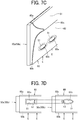
- the reflector open holes 62a in the reflectors 60 and the stay open holes 51 in the side plate stays 50a and 50b may be, for example, elliptical as illustrated in FIG. 7C .
- a direction of the major axis of the ellipse (a longitudinal direction) in each of the reflector open holes 62a and the stay open holes 51 intersects a pressing direction E illustrated in FIG. 7C .
- the reflector open holes 62a and the stay open holes 51 may be formed in a rectangular shape as illustrated in a left drawing of FIG. 7D .
- the rectangular reflector open holes 62a and the rectangular stay open holes 51 that have the same opening width as the elliptical reflector open holes 62a and the elliptical stay open holes 51 have a larger opening widths in the pressing direction E at an end portions in the longitudinal direction of the open holes 62a and 51 than the elliptical reflector open holes 62a and the elliptical stay open holes 51, that is, h1 > h2 as illustrated in FIG. 7D .
- the reflector open holes 62a and the stay open holes 51 are preferably having the elliptical shapes as illustrated in the right drawing of the FIG. 7D rather than having the rectangular shapes as illustrated in the left drawing of the FIG. 7D to obtain suitable opening widths and suitable strengths.
- FIG. 7E is a cross-sectional view of the fixing device 5, which includes the reflectors 60, the side plate stays 50a and 50b, and the halogen heater 42, taken along line E-E of FIG. 7A and seen in the direction of arrows of line E-E.
- the reflector open holes 62a and the stay open holes 51 shift their positions in the width direction of the fixing belt 21, that is, a vertical direction in FIG. 7E , from the other reflector open holes 62a and the other stay open holes 51 on the other side of the halogen heater 42.
- the above-described structure can prevent one area that is irradiated with the infrared light through the reflector open holes 62a and the stay open holes 51 and the other area that is irradiated with the infrared light through the other reflector open holes 62a and the other stay open holes 51 from overlapping in the width direction of the fixing belt 21.
- the above-described structure prevents non-irradiation areas on the fixing belt 21 that are not directly irradiated with the infrared light and correspond to an area between the reflector open holes 62a and the stay open holes 51 from overlapping in the width direction of the fixing belt 21, thereby substantially eliminating or reducing the non-irradiation areas.
- the above-described structure can uniformly heat the fixing belt 21 and prevent fixing failure due to temperature unevenness.
- the two side plate stays 50a and 50b may be arranged not to be parallel to each other but to be inclined so that the distance between the side plate stays 50a and 50b increases upward from the halogen heaters 41 and 42, that is, extends from the nip N to the opposite side.
- the above-described structure can give a larger area on the fixing belt 21 that is directly irradiated with the infrared light from the halogen heater 41 (an upper area in FIG. 8 ) than an area on the nip formation member 24 that is directly irradiated with the infrared light from the halogen heater 42 (a lower area in FIG. 8 ). Since the thermal energy directly applied to the fixing belt 21 increases, the thermal response of the fixing belt 21 to the halogen heaters 41 and 42 can be improved.
- the narrow distance between the two side plate stays 50a and 50b on the nip formation member 24 can reduce the width W of the nip formation member 24 in the belt rotation direction B. Reducing the width W increases the rigidity of the nip formation member 24 with respect to the pressing force of the pressure roller 22 and effectively reduces the bending of the nip formation member 24.
- the above-described structure can also downsize the fixing device 5.
- the two side plate stays 50a and 50b may be coupled each other at both end portions by coupling portions 50c to form one unit. Coupling the two side plate stays 50a and 50b by the coupling portions 50c to form one unit as described above does not need separately assembling and positioning each of the side plate stays 50a and 50b, which improves ease of assembling and maintenance.
- An opening 50d is formed between the coupling portion 50c on the one end and the other coupling portion 50c on the other end, and the halogen heaters 41 and 42 can emit the infrared light through the opening 50d.
- the width Y of the opening 50d is preferably larger than the maximum sheet conveyance span W.
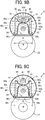
- the upper coupling portion 50c couples the two side plate stays 50a and 50b to form one unit, but, as illustrated in FIG. 9C , a lower coupling portion 50c may couple the side plate stays 50a and 50b to form one unit.
- the halogen heaters 41 and 42 can directly emit the infrared light to both the fixing belt 21 and the nip formation member 24.
- the stay 50 includes the pair of the left side plate stay 50a and the right side plate stay 50b but is not limited to the above-described structure.
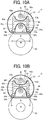
- FIG. 10A is a vertical cross-sectional view of the fixing device viewed from the lateral side of the fixing device including the stay 50 having an H-letter shaped section. In the H-letter shaped section, an intermediate coupling stay 50e couples the pair of the left side plate stay 50a and the right side plate stay 50b.
- Coupling the left side plate stay 50a and the right side plate stay 50b with the coupling stay 50e can increase the rigidity of the stay 50 as a whole. Since the intermediate coupling stay 50e has a small burden ratio of the nip pressure by the pressure roller 22, the intermediate coupling stay 50e is preferably made to be as thin as possible to reduce the thermal capacity.
- the coupling stay 50e may have a plurality of open holes 50f at equal intervals in the longitudinal direction as illustrated in FIGS. 10B and 10C .
- the first reflecting portion 61 positioned over the open holes 50f has a plurality of open holes 61a
- the second reflecting portion 62 positioned under the open holes 50f has a plurality of open holes 62b.
- Overlapping the open holes 50f, 61a, and 62b in the vertical direction gives effects similar to the effects given by providing the gap C as illustrated in FIG. 1B and as described above, such as preventing overheat, discoloration, and deformation of the first reflecting portion 61 and the second reflecting portion 62.
- the size of the open hole 50f of the coupling stay 50e is preferably larger than the open holes 61a in the first reflecting portion 61 and the open holes 62b in the second reflecting portion 62. The above-described configuration can prevent the coupling stay 50e from being directly irradiated with the radiation heat of the halogen heaters 41 and 42.
- the open holes 50f, 61a, and 62b may be alternately formed at different positions in the longitudinal direction.
- the above-described configuration can prevent one of the halogen heaters 41 and 42 from wastefully irradiating the other one of the halogen heaters 41 and 42 with the radiant heat through the open holes 50f, 61a, and 62b.
- the irradiated portion of the coupling stay 50e may be subjected to a mirror surface treatment.
- the shortest distance A from the surface of the halogen heater 41 to the inner surface of the fixing belt 21 may be set larger than the shortest distance B from the surface of the halogen heater 42 to the inner surface of the nip formation member 24. That is, the distance relationship may be limited to A > B.
- the above-described configuration can reduce the risk of the fixing belt 21 contacting the halogen heater 41 even when the fixing belt 21 unstably runs. Additionally, the halogen heater 42 can efficiently irradiate the nip formation member 24 with the radiant heat at the shortest distance B.
- the reflectors 60 including the connector 60c between the first reflecting portion 61 and the second reflecting portion 62 are not limited to the bilaterally symmetric structure as described above.
- the connector at one side may be formed as an extended connector 63 that extends upstream in the sheet conveyance direction D1, and the connector at the other side may be formed as a short connector 64.
- the above-described configuration can reduce irregular reflection compared with the case when the halogen heaters 41 and 42 directly face each other and release excess heat upward.
- the extended connector 63 and the short connector 64 may be interchanged on the upstream side and the downstream side.
- a separating portion 65 may be disposed between the first reflecting portion 61 and the second reflecting portion 62 to separate the first reflecting portion 61 and the second reflecting portion 62.
- Such a configuration can release the heat in the space inside the first reflecting portion 61 and the second reflecting portion 62 upwards and prevent the first reflecting portion and the second reflecting portion from overheating.
- the present disclosure is not limited to those embodiments and variations and can be applied to other embodiments by modification in various forms.
- the fixing device 5 according to the present disclosure is not limited to the fixing device 5 that conveys the sheet in the horizontal direction as illustrated in FIG. 1A .
- a position of the fixing device 5 in the image forming apparatus 1 and the sheet conveyance direction D1 may be suitably changed.
- the present disclosure may be applied to the fixing device 5 that conveys the sheet in the vertical direction.
Landscapes
- Physics & Mathematics (AREA)
- General Physics & Mathematics (AREA)
- Fixing For Electrophotography (AREA)
Abstract
A fixing device (5) includes a fixing member (21), an opposed member (22) opposite the fixing member (21), a nip formation member (24) inside the fixing member (21), a first heat generator (41), a second heat generator (42), first reflecting portions (61), and second reflecting potions (62). The first reflecting portions (61) reflects radiant heat from the first heat generator (41) toward an inner surface of the fixing member (21). The second reflecting portions (62) reflects radiant heat from the second heat generator (42) toward the nip formation member (24). In a medium conveyance direction, the first reflecting portions (61) include an upstream first reflecting portion and a downstream first reflecting portion spaced from the upstream first reflecting portion with a gap, and the second reflecting portions (62) include an upstream second reflecting portion and a downstream second reflecting portion spaced from the upstream second reflecting portion with a gap.
Description
- Embodiments of the present disclosure generally relate to a fixing device and an image forming apparatus incorporating the fixing device.
- An electrophotographic image forming apparatus such as a copier and a printer uses a fixing device. A space-saving fixing device is known in which a heater is disposed inside a loop of a fixing belt and heats the fixing belt and a nip formation member from inside the loop of the fixing belt. In such a fixing device, the heater directly irradiates the nip formation member with radiant heat of the heater, and additionally a heat collection unit collects the radiant heat directed to other than the nip formation member and led to the nip formation member to improve thermal efficiency (for example, see
JP-2014-041172-A - In the fixing device disclosed in
JP-2014-041172-A - However, in the fixing device disclosed in
JP-2014-041172-A - An object of the present disclosure is downsizing the fixing device by increasing the rigidity of the stay and downsizing the stay, and another object is preventing overheat of the reflector.
- It is a general object of the present disclosure to provide an improved and useful fixing device in which the above-mentioned disadvantages are eliminated. In order to achieve the above-mentioned object, there is provided a fixing device according to
claim 1. Advantageous embodiments are defined by the dependent claims. - Advantageously, the fixing device includes a cylindrical fixing member, an opposed member disposed opposite an outer surface of the fixing member, a nip formation member disposed inside a loop of the fixing member to sandwich the fixing member between the nip formation member and the opposed member and form a nip between the nip formation member and the opposed member, a first heat generator disposed inside the loop of the fixing member, a second heat generator disposed inside the loop of the fixing member, a plurality of first reflecting portions, and a plurality of second reflecting portions. The first reflecting portions face the first heat generator and are configured to reflect radiant heat radiated from the first heat generator to the second heat generator toward an inner surface of the fixing member. The first reflecting portions include an upstream first reflecting portion disposed upstream in a medium conveyance direction and a downstream first reflecting portion disposed downstream in the medium conveyance direction and spaced from the upstream first reflecting portion with a gap. The second reflecting portions face the second heat generator and are configured to reflect radiant heat radiated from the second heat generator to the first heat generator toward the nip formation member. The second reflecting portions include an upstream second reflecting portion disposed upstream in the medium conveyance direction and a downstream second reflecting portion disposed downstream in the medium conveyance direction and spaced from the upstream second reflecting portion with a gap.
- According to the present disclosure, the gap between the upstream first reflector and the downstream first reflector and the gap between the upstream second reflector and the downstream second reflector prevent overheat of the first reflector and the second reflector.
- The aforementioned and other aspects, features, and advantages of the present disclosure would be better understood by reference to the following detailed description when considered in connection with the accompanying drawings, wherein:
-
FIG. 1A is a schematic diagram illustrating a configuration of an image forming apparatus according to an embodiment of the present disclosure; -
FIG. 1B is a vertical cross-sectional view of a fixing device viewed from a lateral side of the fixing device; -
FIG. 2 is a perspective view of the fixing device with the vertical cross-sectional view of the fixing device; -
FIG. 3 is a vertical cross-sectional view of the fixing device viewed from a front side of the fixing device; -
FIG. 4A is a perspective view of a belt holder; -
FIG. 4B is a perspective view of a variation of the belt holder; -
FIG. 5 is a vertical cross-sectional view of the fixing device viewed from the lateral side of the fixing device to describe reflection of radiant heat; -
FIG. 6 is a vertical cross-sectional view of the fixing device, which includes reflectors supported via low thermal conduction members, viewed from the lateral side of the fixing device; -
FIG. 7A is a vertical cross-sectional view of the fixing device, which includes a reflector and a stay both provided with open holes, viewed from the lateral side of the fixing device; -
FIG. 7B is a longitudinal sectional view of the reflector and the stay that are provided with open holes; -
FIG. 7C is a partial perspective view illustrating the reflector and the stay that are provided with open holes; -
FIG. 7D is a diagram partially illustrating side views of exemplary reflectors and stays with open holes; -
FIG. 7E is a cross-sectional view taken along line E-E ofFIG. 7A and seen in the direction of arrows of line E-E; -
FIG. 8 is a vertical cross-sectional view of the fixing device, which includes two side plate stays inclined to each other, viewed from the lateral side of the fixing device; -
FIG. 9A is a perspective view illustrating an example in which two side plate stays are configured as one unit; -
FIG. 9B is a vertical cross-sectional view of the fixing device, which includes a stay having an upper coupling portion that connects two side plate stays, viewed from the lateral side of the fixing device; -
FIG. 9C is a vertical cross-sectional view of the fixing device, which includes a stay having a lower coupling portion that connects two side plate stays, viewed from the lateral side of the fixing device; -
FIG. 10A is a vertical cross-sectional view of a variation of the fixing device that includes a different reflector and a different stay, as viewed from the lateral side of the fixing device; -
FIG. 10B is a vertical cross-sectional view of a variation of the fixing device illustrated inFIG. 10A that includes the stay having open holes; -
FIG. 10C is a partial perspective view illustrating the stay and the reflector that are illustrated inFIG. 10B ; -
FIG. 11 is a vertical cross-sectional view illustrating one of other variations of the fixing device viewed from the lateral side of the fixing device; -
FIG. 12 is a vertical cross-sectional view illustrating one of other variations of the fixing device viewed from the lateral side of the fixing device; -
FIG. 13 is a vertical cross-sectional view illustrating one of other variations of the fixing device viewed from the lateral side of the fixing device; and -
FIG. 14 is a schematic diagram illustrating an example of an image forming apparatus including the fixing device that conveys a sheet in a vertical direction. - The accompanying drawings are intended to depict embodiments of the present disclosure and should not be interpreted to limit the scope thereof. The accompanying drawings are not to be considered as drawn to scale unless explicitly noted.
- In describing embodiments illustrated in the drawings, specific terminology is employed for the sake of clarity. However, the disclosure of this specification is not intended to be limited to the specific terminology so selected and it is to be understood that each specific element includes all technical equivalents that have a similar function, operate in a similar manner, and achieve a similar result.
- Although the embodiments are described with technical limitations with reference to the attached drawings, such description is not intended to limit the scope of the disclosure and all of the components or elements described in the embodiments of this disclosure are not necessarily indispensable.
- A description is given of embodiments of the present disclosure below, with reference to the drawings attached. In the drawings for describing the embodiments of the present disclosure, identical reference numerals are assigned to elements such as members and parts that have an identical function or an identical shape as long as differentiation is possible, and a description of those elements is omitted once the description is provided.
- Structure of an image forming apparatus is described below.
-
FIG. 1 is a schematic cross-sectional view of the image forming apparatus according to an embodiment of the present disclosure. Referring toFIG. 1 , a configuration and operation of the image forming apparatus according to the present embodiment are described below. - An
image forming apparatus 1 illustrated inFIG. 1 is a monochrome electrophotographic laser printer. Theimage forming apparatus 1 according to an embodiment of the present disclosure may be a copier, a facsimile machine, a multifunction peripheral (MFP) having at least two of copying, printing, scanning, facsimile, and plotter functions in addition to the printer. Theimage forming apparatus 1 is not limited to a monochrome image forming apparatus and may be a color image forming apparatus. - As illustrated in
FIG. 1 , theimage forming apparatus 1 includes animage forming device 2 to form an image, a recordingmedium feeding device 3 to feed a sheet P as a recording medium to theimage forming device 2, a transfer device 4 to transfer the image onto the fed sheet P, a fixingdevice 5 to fix the image transferred onto the sheet P, and asheet ejection device 6 to eject the sheet P with the fixed image to an outside of theimage forming apparatus 1. - The
image forming device 2 includes a drum-shapedphotoconductor 7, a chargingroller 8 as a charging device to charge a surface of thephotoconductor 7, anexposure device 9 as a latent image forming device that exposes the surface of thephotoconductor 7 to form an electrostatic latent image on thephotoconductor 7, a developingroller 10 as a developing device that supplies toner as a developer to the surface of thephotoconductor 7 to visualize the electrostatic latent image, and acleaning blade 11 as a cleaner to clean the surface of thephotoconductor 7. - As an image forming operation start is instructed, in the
image forming device 2, thephotoconductor 7 starts to rotate, and the chargingroller 8 uniformly charges the surface of thephotoconductor 7 to a high potential. Next, based on image data of an original document read by a scanner or print data instructed by a terminal device, theexposure device 9 exposes the surface of thephotoconductor 7. Potential of an exposed surface drops, and the electrostatic latent image is formed on thephotoconductor 7. The developingroller 10 supplies toner to the electrostatic latent image, thereby developing the latent image into the toner image on thephotoconductor 7. - The toner image formed on the
photoconductor 7 is transferred onto the sheet P in a transfer nip between thephotoconductor 7 and atransfer roller 15 disposed in the transfer device 4. The sheet P is fed from the recordingmedium feeding device 3. In the recordingmedium feeding device 3, asheet feeding roller 13 feeds the sheet P from asheet tray 12 to a feeding path one by one. - A
timing roller pair 14 sends out the sheet P fed from thesheet tray 12 to a transfer nip, timed to coincide with the toner image on thephotoconductor 7. The toner image on thephotoconductor 7 is transferred onto the sheet P at the transfer nip. After the toner image is transferred from thephotoconductors 7 onto the sheet P, thecleaning blade 11 removes residual toner on thephotoconductor 7. - The sheet P bearing the toner image is conveyed to the
fixing device 5. In thefixing device 5, heat and pressure when the sheet P passes through between a fixingbelt 21 and apressure roller 22 fixes the toner image onto the sheet P. Subsequently, the sheet P is conveyed to thesheet ejection device 6, and anejection roller pair 16 ejects the sheet P outside theimage forming apparatus 1, and a series of print operations are completed. - With reference to
FIGS. 1B to 14 , a detailed description is provided of a construction of the fixingdevice 5. -
FIG. 1B is a vertical cross-sectional view of the fixingdevice 5 viewed from a lateral side of the fixingdevice 5,FIG. 2 is a perspective view of the fixingdevice 5 with the vertical cross-sectional view of the fixingdevice 5, andFIG. 3 is a vertical cross-sectional view of the fixingdevice 5 viewed from a front side of the fixingdevice 5. In addition,FIG. 4A is a perspective view of abelt holder 30 to support the fixingbelt 21, andFIG. 4B is a perspective view of a variation of thebelt holder 30. - As illustrated in
FIGS. 1B and2 , the fixingdevice 5 includes the fixingbelt 21, thepressure roller 22,halogen heaters nip formation member 24, astay 50 configured by a pair of side plate stays 50a and 50b arranged in right and left, a pair ofreflectors 60 arranged in right and left, andtemperature sensors 28. - The fixing
belt 21 is a cylindrical fixing member to fix an unfixed image T to the sheet P and is disposed on the side of the sheet P on which the unfixed image is held. The fixingbelt 21 in the present embodiment is an endless belt or film, including a base layer formed on an inner side of the fixingbelt 21 and made of a metal such as nickel and stainless steel (SUS) or a resin such as polyimide, and a release layer formed on an outer side of the fixingbelt 21 and made of tetrafluoroethylene-perfluoroalkylvinylether copolymer (PFA), polytetrafluoroethylene (PTFE), or the like. - Optionally, an elastic layer made of rubber such as silicone rubber, silicone rubber foam, and fluoro rubber may be interposed between the base layer and the release layer. While the fixing
belt 21 and thepressure roller 22 press the unfixed toner image against the sheet P to fix the toner image onto the sheet P, the elastic layer having a thickness of about 100 micrometers elastically deforms to absorb slight surface asperities of the fixingbelt 21, preventing variation in gloss of the toner image on the sheet P. - Additionally, in the present embodiment, the fixing
belt 21 is thin and has a small loop diameter to decrease the thermal capacity of the fixingbelt 21. For example, the base layer of the fixingbelt 21 has a thickness of from 20 µm to 50 µm, and the release layer has a thickness of from 10 µm to 50 µm. Thus, the fixingbelt 21 has a total thickness not greater than 1 mm. - In addition, when the fixing
belt 21 includes the elastic layer, the thickness of the elastic layer may be set to 100 to 300 µm. In order to further decrease the thermal capacity of the fixingbelt 21, the fixingbelt 21 may have the total thickness not greater than 0.20 mm and preferably not greater than 0.16 mm. In the present embodiment, the fixingbelt 21 may have a loop diameter from 20 to 40 mm and preferably 30 mm or less. - The
pressure roller 22 is an opposed member disposed opposite an outer circumferential surface of the fixingbelt 21. Thepressure roller 22 has a length equal to or greater than the maximum sheet width and faces thenip formation member 24 along a longitudinal direction of thenip formation member 24 as illustrated inFIG. 3 . Thepressure roller 22 is applied with a pressing force in an upward direction indicated by arrow P illustrated inFIG. 3 by a spring or a movable arm. - The
pressure roller 22 includes a cored bar; an elastic layer coating the cored bar and being made of silicone rubber foam, fluoro rubber, or the like; and a release layer coating the elastic layer and being made of PFA, PTFE, or the like. According to the present embodiment, thepressure roller 22 is a solid roller. Alternatively, thepressure roller 22 may be a hollow roller. When thepressure roller 22 is the hollow roller, a heater such as a halogen heater may be disposed inside thepressure roller 22. - The elastic layer of the
pressure roller 22 may be made of solid rubber. Alternatively, if no heater is disposed inside thepressure roller 22, the elastic layer of thepressure roller 22 is preferably made of sponge rubber to enhance thermal insulation of thepressure roller 22. Such a configuration reduces heat conduction from the fixingbelt 21 to thepressure roller 22 and improves heating efficiency of the fixingbelt 21. - A driver disposed inside the
image forming apparatus 1 drives and rotates thepressure roller 22 in a direction indicated by arrow A inFIG. 1B . The rotation of thepressure roller 22 drives the fixingbelt 21 to rotate in a direction B inFIG. 1B due to frictional force therebetween. - After the toner image is transferred onto the sheet P, the sheet P bearing the unfixed toner image is conveyed to a nip N between the fixing
belt 21 and thepressure roller 22. Therotating fixing belt 21 and therotating pressure roller 22 conveys the sheet P, and the sheet P passes through the nip N. When the sheet P passes through the fixing nip N, heat and pressure applied to the sheet P fix the unfixed toner image T onto the sheet P. - The
pressure roller 22 and the fixingbelt 21 are configured to be able to contact and separate each other. If the sheet is jammed in the nip N, separating thepressure roller 22 and the fixingbelt 21 from each other and opening the nip N enables the jammed sheet to be removed. One of thepressure roller 22 and the fixingbelt 21 may be configured to be fixed and the other may be configured to be movable so that thepressure roller 22 and the fixingbelt 21 contact and separate each other. Alternatively, both thepressure roller 22 and the fixingbelt 21 may be configured to move so that thepressure roller 22 and the fixingbelt 21 contact and separate each other. -
Halogen heaters belt 21. Thehalogen heater 42 is disposed closer to thepressure roller 22 than thehalogen heater 41. - The
halogen heaters halogen heaters belt 21 from the inside. Thehalogen heaters belt 21 in a width direction of the fixingbelt 21, and the other heater may heat end portions of the fixingbelt 21 in the width direction. - That is, the
halogen heaters halogen heaters - The
nip formation member 24 and thepressure roller 22 sandwich the fixingbelt 21 to form the nip N. Specifically, thenip formation member 24 is disposed inside the loop of the fixingbelt 21 and extends in a longitudinal direction of thenip formation member 24 parallel to the width direction of the fixingbelt 21. - The
nip formation member 24 includes a nipformation portion 24a that is a plate to contact the inner circumferential surface of the fixingbelt 21 and a pair ofbent portions 24b that are bent from both end portions of thenip formation portion 24a in a belt rotation direction B to the opposite side to thepressure roller 22. A pressure member such as a spring presses thepressure roller 22 against thenip formation member 24, which causes thepressure roller 22 to contact the fixingbelt 21 and forms the nip N therebetween. - A
nip formation surface 24c on thenip formation portion 24a facing the fixingbelt 21 directly contacts the inner circumferential surface of the fixingbelt 21. Therefore, when the fixingbelt 21 rotates, the fixingbelt 21 slides along thenip formation surface 24c. - In order to improve the abrasion resistance and the slidability of the
nip formation surface 24c, thenip formation surface 24c may be treated with alumite or coated with fluororesin material. Additionally, a lubricant such as a fluorine-based grease may be applied to thenip formation surface 24c to ensure slidability over time. - In the present embodiment, the
nip formation surface 24c is planar. Alternatively, thenip formation surface 24c may define a recess or other shape. For example, thenip formation surface 24c having a concave shape recessed to the side opposite to thepressure roller 22 leads the outlet of the sheet in the fixing nip N to be closer to thepressure roller 22, which improves separation of the sheet from the fixingbelt 21. - The
nip formation member 24 is made of a material having a thermal conductivity larger than a thermal conductivity of thestay 50. For example, the material of thenip formation member 24 is preferably copper (thermal conductivity: 398 W/mK) or aluminum (thermal conductivity: 236 W/mK). - The
nip formation member 24 made of the material having such a large thermal conductivity absorbs the radiant heat from thehalogen heaters belt 21. For example, setting the thickness of thenip formation member 24 to 1 mm or less can shorten a heat transfer time in which the heat transfers from thenip formation member 24 to the fixingbelt 21, which is advantageous in shortening a warm-up time of the fixingdevice 5. In contrast, setting the thickness of thenip formation member 24 to be larger than 1 mm and 5 mm or less can improve a heat storage capacity of thenip formation member 24. - The structure of the
stay 50 is described below. - The
stay 50 is a support to support thenip formation member 24 against the pressing force of thepressure roller 22. Thestay 50 has the pair of side plate stays 50a and 50b arranged in right and left and facing each other. Oneside plate stay 50a is arranged on the inlet side of the nip N as the first main body of thestay 50, and the otherside plate stay 50b is arranged on the outlet side of the nip N as the second main body of thestay 50. The inlet of the nip N is at a position at which the circumferential surface of thepressure roller 22 illustrated inFIG. 1B starts to contact the fixingbelt 21. The outlet of the nip N is at a position at which the circumferential surface of thepressure roller 22 separates from the fixingbelt 21. - The side plate stays 50a and 50b have a cross-section like a plate extending in a direction from the
pressure roller 22 as the opposed member toward the fixingbelt 21. In such a configuration, the side plate stays with a minimum thickness and height can efficiently and stably receive the pressing force of thepressure roller 22. Similar to the nipformation member 24, the side plate stays 50a and 50b extend in a longitudinal direction thereof parallel to the width direction of the fixingbelt 21 and is disposed inside the loop of the fixingbelt 21. - Since the side plate stays 50a and 50b basically have a shape that does not require bending or opening, the side plate stays 50a and 50b can be made simply and at low cost. A cross-sectional shape of the side plate stays 50a and 50b that can efficiently receive the pressing force applied by the
pressure roller 22 can minimize heights of the side plate stays 50a and 50b and downsize the configuration of thestay 50, which can reduce the diameter of the fixingbelt 21. - Since a distance between the side plate stays 50a and 50b can be widely set, the
upper halogen heater 41 can directly heat a large area of the fixingbelt 21, and heat radiation to the side plate stays 50a and 50b can be reduced, which reduces an amount of heat stored in the side plate stays 50a and 50b. - As described above, since the fixing
device 5 according to the present embodiment can increase the thermal efficiency with a simple configuration, the fixingdevice 5 can obtain high-speed heating characteristics even if the fixing device includes the relativelythick fixing belt 21 having an elastic layer, and a high-quality on-demand fixing device 5 can be obtained. - Next, a reflector in the present embodiment is described.
- A pair of
reflectors 60 are arranged upstream and downstream in a sheet conveyance direction indicated by arrow D1 illustrated inFIG. 1 and inside the side plate stays 50a and 50b to face thehalogen heaters reflector 60 includes a first reflectingportion 61 located on an upper side inFIG. 1B and a second reflectingportion 62 located on a lower side inFIG. 1B . In the present embodiment, the first reflectingportion 61 is located on a lateral side of thehalogen heater 41, and the second reflectingportion 62 is located on a lateral side of thehalogen heater 42. The cross-sectional shapes of the first reflectingportion 61 and the second reflectingportion 62 in a transverse direction of thereflector 60 are each curved as part of an elliptical shape and are different from each other. Anupstream connector 60c as an upstream coupling portion connects the first reflectingportion 61 and the second reflectingportion 62 on the upstream side in the sheet conveyance direction, and adownstream connector 60c as a downstream coupling portion connects the first reflectingportion 61 and the right second reflectingportion 62 on the downstream side in the sheet conveyance direction D1. - Making the first reflecting
portion 61 and the second reflectingportion 62 have transverse sections of different curved shapes as described above causes the first reflectingportion 61 to efficiently reflect radiant heat from thehalogen heater 41 toward the fixingbelt 21 and the second reflectingportion 62 to efficiently reflect radiant heat from thehalogen heater 42 toward an inner surface of thenip formation member 24. An optimum distance between thehalogen heaters 41 and the first reflectingportion 61 is different from an optimum distance between thehalogen heater 42 and the second reflectingportion 62. Preferably, the curvature is larger as the distance between the heater and the reflector is shorter. - As described below with reference to
FIGS. 11 to 13 , to avoid contact between the fixingbelt 21 and thehalogen heater 41, a distance A between thehalogen heater 41 and the fixingbelt 21 is set larger than the shortest distance B between thehalogen heater 42 and thenip formation member 24, that is, A > B. The above-described configuration can realize effective use of radiant heat and downsizing of the fixing device. The cross-sectional shapes of the first reflectingportion 61 and the second reflectingportion 62 in the transverse direction of thereflector 60 may be the same curved shape. The above-described configuration enables the right reflectors and the left reflectors illustrated inFIG. 1B to be the same parts, which reduces a number of parts, improves ease of assembling, and achieves a reduction in manufacturing cost. - The
upper end portion 60a and thelower end portion 60b of thereflector 60 are bent toward outside in an L shape and engaged with the upper and lower end portions of the side plate stays 50a and 50b. In addition, theconnector 60c is positioned between theupper end portion 60a and thelower end portion 60b of thereflector 60, connects the first reflectingportion 61 and the second reflectingportion 62, and faces theother connector 60c that connects theopposite reflectors 60 through a slight gap C. - The
reflector 60 is made of a stainless-steel plate or a bright aluminum plate having heat resistance and elasticity. The L-shapedupper end portion 60a and the L-shapedlower end portion 60b are elastically expanded in a direction away from each other and engaged with the upper and lower end portions of the side plate stays 50a and 50b, and thereflector 60 can be easily mounted. - Since the
upper halogen heater 41 as the first heat generator is positioned near a focus of an ellipse of the first reflectingportion 61, the first reflectingportion 61 efficiently reflects the radiant heat radiated from thehalogen heater 41 downward (particularly toward the lower halogen heater 42), and the reflected radiant heat is irradiated onto the upper inner surface of the fixingbelt 21. The radiant heat (infrared light) radiated from thehalogen heater 41 upward and sideways directly reaches the upper inner surface of the fixingbelt 21. - On the other hand, Since the
lower halogen heater 42 as the second heat generator is positioned near a focus of an ellipse of the second reflectingportion 62, the second reflectingportion 62 efficiently reflects the radiant heat radiated from thehalogen heater 42 sideways and upward (particularly toward the upper halogen heater 41), and the reflected radiant heat is irradiated onto the inner surface of thenip formation member 24. The radiant heat (infrared light) radiated from thehalogen heater 42 downward directly reaches the inner surface of thenip formation member 24. - That is, the above-described structure can avoid useless heating in which one halogen heater 41 (42) heats the other halogen heater 42 (41). To obtain the above-described effect, it is preferable that the above-described gap C is small. The gap C is set to prevent the two
reflectors 60 from contacting and deforming due to component accuracy, assembly error, or linear expansion caused by temperature rise in thereflectors 60. The gap C is preferably 5 mm or less, more preferably 2 mm or less. Even if the gap C is very small, an air layer between the gap C reduces heat transfer between the right reflector and the left reflector. - Since a space around the
lower halogen heater 42 is surrounded by the second reflectingportion 62 and thenip formation member 24, the space stores heat, and parts in the space tend to overheat. The above-described overheating may cause serious disadvantages as the fixingdevice 5 is downsized. - The second reflecting
portion 62 adjacent to thehalogen heater 42 exposed to a high temperature for a long time due to continuously printing many sheets may cause such a disadvantage that the surface of the second reflectingportion 62 is discolored over time to yellow or gold. The disadvantage with discoloration is remarkable when a bright aluminum alloy having a high reflectance capable of obtaining high light brightness is used for thereflector 60. - The discolored surface of the second reflecting
portion 62 causes a decrease in the reflectance of the second reflectingportion 62 and a decrease in the radiant heat to the fixingbelt 21, which causes difficulty to raise the temperature of the fixingbelt 21, resulting in increase of warm-up time. The radiant heat of thehalogen heater 42 not reflected by the second reflectingportion 62 is stored in the space surrounded by the second reflectingportion 62 and causes the further increase in the temperature of the second reflectingportion 62, which causes disadvantages such as acceleration of the discoloration and deformation of the surface of the second reflectingportion 62 caused by thermal expansion of the second reflectingportion 62. - In the embodiment of the present disclosure, since the slight gap C is formed between the
connectors 60c of thereflector 60, excess heat can escape upward through the gap C. Since the above-described structure prevents the second reflectingportion 62 from being discolored due to overheating, the second reflectingportion 62 can efficiently reflect the radiant heat radiated sideward and upward from thehalogen heater 42 to irradiate the inner surface of thenip formation member 24. In addition, when the first reflectingportion 61 or the second reflectingportion 62 is locally overheated, theconnector 60c can conduct the heat to the reflector not overheated to diffuse the heat uniformly in the upper side and the lower side, which can prevent thereflector 60 from overheating (discoloring and deforming). - Although heat tends to be unevenly distributed and stay around the
halogen heaters belt 21 to be uniform. That is, through the gap C, the heat moves from the upper side to the lower side, or, from the lower side to the upper side so that the unevenly distributed heat is uniformly distributed, which enables the temperature of the fixingbelt 21 to be uniform. The size of the gap C may be set to 2 mm or more in order to prevent the tworeflectors 60 from contacting and deforming due to component accuracy, assembly error, or linear expansion due to the temperature rise of thereflector 60. As described above, the heat stored in the space (air) can move through the gap C, and connecting the first reflectingportion 61 located on the upper side and the second reflectingportion 62 located on the lower side enables the heat locally distributed on one reflector to move to the other reflector. Forming the gap C at the center in the sheet conveyance direction D1 as illustrated inFIG. 1B enables the left andright reflectors 60 to be a common part, thereby reducing the number of parts, improving ease of assembling, and achieving the reduction in manufacturing cost. - Since the
reflectors 60 exists between thehalogen heaters reflectors 60 also functions to block irradiation of infrared light from thehalogen heaters reflectors 60 further blocks heat transfer to the side plate stays 50a and 50b. - The surfaces of the
reflectors 60, that is, the first reflectingportion 61 and the second reflectingportion 62, facing thehalogen heaters - In general, the color temperature of the halogen heater varies depending on the application. The color temperature of the heater for the fixing device is about 2500 K. The reflectance of the
reflector 60 used in the present embodiment is preferably 70% or more with wavelengths of high emission intensity in thehalogen heaters - Alternatively, the side plate stays 50a and 50b may have the function of reflection and thermal insulation of the
reflector 60. For example, performing the thermal insulation treatment or the mirror finishing on the inner surface of the side plate stays 50a and 50b facing thehalogen heaters reflector 60. Such a configuration can obviate thereflectors 60 that are separate components from the side plate stays 50a and 50b. The reflectance of each of the side plate stays 50a and 50b subjected to the mirror finishing is preferably similar to the reflectance of thereflector 60. - The
temperature sensors 28 are disposed near the inlet of the fixing nip N outside the loop of the fixingbelt 21 and detects temperatures of the fixingbelt 21. In the present embodiment, thetemperature sensors 28 are disposed at two positions, the central position in the width direction of the fixingbelt 21, and one end position in the belt width direction of the fixingbelt 21. - Outputs of the
halogen heaters belt 21 detected by thetemperature sensors 28. Thus, the temperature of the fixingbelt 21 is adjusted to a desired fixing temperature. - The
temperature sensor 28 may be either contact type or non-contact type. Thetemperature sensor 28 may be a known temperature sensor type such as a thermopile, a thermostat, a thermistor, or a non-contact (NC) sensor. - A description is provided of a fixing belt support structure.
- As illustrated in
FIG. 3 , a pair ofbelt holders 30 is inserted in both lateral ends of the fixingbelt 21 to rotatably support the fixingbelt 21. As described above, thebelt holders 30 inserted into the inner periphery of the fixingbelt 21 support the fixingbelt 21 in a state in which the fixingbelt 21 is not basically applied with tension in a circumferential direction thereof while the fixingbelt 21 does not rotate, that is, by a free belt system. - As illustrated in
FIGS. 2 to 4A , thebelt holder 30 includes a C-shapedsupporter 30a to be inserted into the inner periphery of the fixingbelt 21 and support the fixingbelt 21 and aflange 30b that contacts an end face of the fixingbelt 21 to stop a movement of the fixingbelt 21 in the width direction, that is, walking of the fixingbelt 21 in the width direction. Since both end edges of the fixingbelt 21 contact theflange 30b via lubricant, the fixingbelt 21 can stably rotate without meandering. - As illustrated in
FIG. 4B , thesupporter 30a may have a cylindrical shape which is continuous over its entire circumference. As illustrated inFIG. 3 , each of thebelt holders 30 is fixed on a pair ofside plates 31 that are frames of the fixingdevice 5. - The
belt holder 30 has anopening 30c (seeFIGS. 4A and 4B ), and both ends of thehalogen heaters side plates 31 through theopenings 30c. Thehalogen heaters belt holder 30. - As illustrated in
FIG. 6 , a lowheat conduction member 70 made of heat-resistant resin or the like may be interposed between each of the upper end of theside plate stay 50a and theupper end portion 60a of thereflector 60, the upper end of theside plate stay 50b and theupper end portion 60a of thereflector 60, the lower end of theside plate stay 50a and thelower end portion 60b of thereflector 60, and the lower end of theside plate stay 50b and thelower end portion 60b of thereflector 60. Setting the lowheat conduction member 70 can reduce amounts of heat flowing from thereflectors 60 to the side plate stays 50a and 50b and improves the thermal efficiency. - Since the
lower end portion 60b of thereflector 60 contacts the inner surface of thenip formation member 24, the temperature at thelower end portion 60b is lower than the temperature at theupper end portion 60a. Therefore, the necessity for interposing the lowheat conduction member 70 between thelower end portions 60b and the lower ends of the side plate stays 50a and 50b is not as high as the necessity for interposing the lowheat conduction member 70 between theupper end portions 60a and the upper ends of the side plate stays 50a and 50b. Interposing the lowheat conduction member 70 between theupper end portions 60a and the upper ends of the side plate stays 50a and 50b can sufficiently improve thermal efficiency. - Open holes to make radiant heat pass through are described below.
- As illustrated in
FIGS. 7A and 7B , reflectoropen holes 62a may be formed in the second reflectingportions 62, and stayopen holes 51 may be formed in the side plate stays 50a and 50b. Without the reflectoropen holes 62a and the stayopen holes 51, the radiant heat radiated in the horizontal direction inFIG. 7A from thelower halogen heater 42 is applied to the second reflectingportion 62 in the horizontal direction and hardly reflected toward thenip formation member 24. - Therefore, when there are not the reflector
open holes 62a and the stayopen holes 51, the radiant heat radiated in the horizontal direction can not be effectively used for heating the fixingbelt 21. Through the reflectoropen holes 62a and the stayopen holes 51, the fixingbelt 21 can be irradiated with the radiant heat from thehalogen heater 42. As a result, thermal efficiency can be improved. - As illustrated in
FIGS. 7A and 7B , the size of the reflectoropen holes 62a in the second reflectingportion 62 is smaller than the size of the stayopen holes 51 in the side plate stays 50a and 50b. This is to prevent the radiant heat in the horizontal direction from being applied to the side plate stays 50a and 50b. - The reflector
open holes 62a in thereflectors 60 and the stayopen holes 51 in the side plate stays 50a and 50b may be, for example, elliptical as illustrated inFIG. 7C . Preferably, a direction of the major axis of the ellipse (a longitudinal direction) in each of the reflectoropen holes 62a and the stayopen holes 51 intersects a pressing direction E illustrated inFIG. 7C . - That is, since the pressing force of the
pressure roller 22 is applied to thereflectors 60 and thestay 50 in the pressing direction indicated by arrow E illustrated inFIG. 7C , largely forming the reflectoropen holes 62a and the stayopen holes 51 in the pressing direction is not preferable to secure the strength of thereflectors 60 and thestay 50 with respect to the direction E. Forming the reflectoropen holes 62a and the stayopen holes 51 as illustrated inFIG. 7C does not decrease a section modulus of thestay 50 and can ensure the necessary strength of thestay 50. - The reflector
open holes 62a and the stayopen holes 51 may be formed in a rectangular shape as illustrated in a left drawing ofFIG. 7D . However, as illustrated inFIG. 7D , the rectangular reflectoropen holes 62a and the rectangular stayopen holes 51 that have the same opening width as the elliptical reflectoropen holes 62a and the elliptical stayopen holes 51 have a larger opening widths in the pressing direction E at an end portions in the longitudinal direction of theopen holes open holes 62a and the elliptical stayopen holes 51, that is, h1 > h2 as illustrated inFIG. 7D . Therefore, the reflectoropen holes 62a and the stayopen holes 51 are preferably having the elliptical shapes as illustrated in the right drawing of theFIG. 7D rather than having the rectangular shapes as illustrated in the left drawing of theFIG. 7D to obtain suitable opening widths and suitable strengths. -
FIG. 7E is a cross-sectional view of the fixingdevice 5, which includes thereflectors 60, the side plate stays 50a and 50b, and thehalogen heater 42, taken along line E-E ofFIG. 7A and seen in the direction of arrows of line E-E. As illustrated inFIG. 7E , preferably, the reflectoropen holes 62a and the stayopen holes 51 shift their positions in the width direction of the fixingbelt 21, that is, a vertical direction inFIG. 7E , from the other reflectoropen holes 62a and the other stayopen holes 51 on the other side of thehalogen heater 42. The above-described structure can prevent one area that is irradiated with the infrared light through the reflectoropen holes 62a and the stayopen holes 51 and the other area that is irradiated with the infrared light through the other reflectoropen holes 62a and the other stayopen holes 51 from overlapping in the width direction of the fixingbelt 21. - That is, the above-described structure prevents non-irradiation areas on the fixing
belt 21 that are not directly irradiated with the infrared light and correspond to an area between the reflectoropen holes 62a and the stayopen holes 51 from overlapping in the width direction of the fixingbelt 21, thereby substantially eliminating or reducing the non-irradiation areas. As a result, the above-described structure can uniformly heat the fixingbelt 21 and prevent fixing failure due to temperature unevenness. - Variations of the side plate stays are described below.
- As in the
fixing device 5 illustrated inFIG. 8 , the two side plate stays 50a and 50b may be arranged not to be parallel to each other but to be inclined so that the distance between the side plate stays 50a and 50b increases upward from thehalogen heaters belt 21 that is directly irradiated with the infrared light from the halogen heater 41 (an upper area inFIG. 8 ) than an area on thenip formation member 24 that is directly irradiated with the infrared light from the halogen heater 42 (a lower area inFIG. 8 ). Since the thermal energy directly applied to the fixingbelt 21 increases, the thermal response of the fixingbelt 21 to thehalogen heaters - Additionally, as illustrated in
FIG. 8 , the narrow distance between the two side plate stays 50a and 50b on thenip formation member 24 can reduce the width W of thenip formation member 24 in the belt rotation direction B. Reducing the width W increases the rigidity of thenip formation member 24 with respect to the pressing force of thepressure roller 22 and effectively reduces the bending of thenip formation member 24. The above-described structure can also downsize thefixing device 5. - Alternatively, as illustrated in
FIGS. 9A and9B , the two side plate stays 50a and 50b may be coupled each other at both end portions by couplingportions 50c to form one unit. Coupling the two side plate stays 50a and 50b by thecoupling portions 50c to form one unit as described above does not need separately assembling and positioning each of the side plate stays 50a and 50b, which improves ease of assembling and maintenance. - An
opening 50d is formed between thecoupling portion 50c on the one end and theother coupling portion 50c on the other end, and thehalogen heaters opening 50d. To secure an enough irradiation width of infrared light, the width Y of theopening 50d is preferably larger than the maximum sheet conveyance span W. - In
FIGS. 9A and9B , theupper coupling portion 50c couples the two side plate stays 50a and 50b to form one unit, but, as illustrated inFIG. 9C , alower coupling portion 50c may couple the side plate stays 50a and 50b to form one unit. In any variation, thehalogen heaters belt 21 and thenip formation member 24. - In the embodiment described above, the
stay 50 includes the pair of the leftside plate stay 50a and the rightside plate stay 50b but is not limited to the above-described structure.FIG. 10A is a vertical cross-sectional view of the fixing device viewed from the lateral side of the fixing device including thestay 50 having an H-letter shaped section. In the H-letter shaped section, anintermediate coupling stay 50e couples the pair of the leftside plate stay 50a and the rightside plate stay 50b. - Coupling the left
side plate stay 50a and the rightside plate stay 50b with thecoupling stay 50e can increase the rigidity of thestay 50 as a whole. Since theintermediate coupling stay 50e has a small burden ratio of the nip pressure by thepressure roller 22, theintermediate coupling stay 50e is preferably made to be as thin as possible to reduce the thermal capacity. - However, using the
stay 50 having the H-letter shaped section as illustrated inFIG. 10A tends to cause storing heat in the space around thelower halogen heater 42 as the fixingdevice 5 is reduced in size, which is likely to cause overheating. Therefore, in order to prevent the overheating, thecoupling stay 50e may have a plurality ofopen holes 50f at equal intervals in the longitudinal direction as illustrated inFIGS. 10B and10C . The first reflectingportion 61 positioned over theopen holes 50f has a plurality ofopen holes 61a, and the second reflectingportion 62 positioned under theopen holes 50f has a plurality ofopen holes 62b. - Overlapping the
open holes FIG. 1B and as described above, such as preventing overheat, discoloration, and deformation of the first reflectingportion 61 and the second reflectingportion 62. In the above-described structure, the size of theopen hole 50f of thecoupling stay 50e is preferably larger than theopen holes 61a in the first reflectingportion 61 and theopen holes 62b in the second reflectingportion 62. The above-described configuration can prevent thecoupling stay 50e from being directly irradiated with the radiation heat of thehalogen heaters - Alternatively, the
open holes halogen heaters halogen heaters open holes halogen heaters coupling stay 50e through theopen holes coupling stay 50e may be subjected to a mirror surface treatment. - Other variations are described below.
- As illustrated in
FIGS. 11 to 13 , the shortest distance A from the surface of thehalogen heater 41 to the inner surface of the fixingbelt 21 may be set larger than the shortest distance B from the surface of thehalogen heater 42 to the inner surface of thenip formation member 24. That is, the distance relationship may be limited to A > B. The above-described configuration can reduce the risk of the fixingbelt 21 contacting thehalogen heater 41 even when the fixingbelt 21 unstably runs. Additionally, thehalogen heater 42 can efficiently irradiate thenip formation member 24 with the radiant heat at the shortest distance B. - The
reflectors 60 including theconnector 60c between the first reflectingportion 61 and the second reflectingportion 62 are not limited to the bilaterally symmetric structure as described above. As illustrated inFIG. 12 , the connector at one side may be formed as anextended connector 63 that extends upstream in the sheet conveyance direction D1, and the connector at the other side may be formed as ashort connector 64. The above-described configuration can reduce irregular reflection compared with the case when thehalogen heaters extended connector 63 and theshort connector 64 may be interchanged on the upstream side and the downstream side. - Alternatively, as illustrated in
FIG. 13 , a separatingportion 65 may be disposed between the first reflectingportion 61 and the second reflectingportion 62 to separate the first reflectingportion 61 and the second reflectingportion 62. Such a configuration can release the heat in the space inside the first reflectingportion 61 and the second reflectingportion 62 upwards and prevent the first reflecting portion and the second reflecting portion from overheating. - Although the embodiments and the variations of the present disclosure are described above, the present disclosure is not limited to those embodiments and variations and can be applied to other embodiments by modification in various forms. For example, the fixing
device 5 according to the present disclosure is not limited to thefixing device 5 that conveys the sheet in the horizontal direction as illustrated inFIG. 1A . A position of the fixingdevice 5 in theimage forming apparatus 1 and the sheet conveyance direction D1 may be suitably changed. For example, as illustrated inFIG. 14 , the present disclosure may be applied to thefixing device 5 that conveys the sheet in the vertical direction. - Numerous additional modifications and variations are possible in light of the above teachings. It is therefore to be understood that, within the scope of the above teachings, the present disclosure may be practiced otherwise than as specifically described herein. With some embodiments having thus been described, it will be obvious that the same may be varied in many ways. Such variations are not to be regarded as a departure from the scope of the present disclosure and appended claims, and all such modifications are intended to be included within the scope of the present disclosure and appended claims.
Claims (11)
- A fixing device (5) comprising:a fixing member (21) in a cylindrical shape;an opposed member (22) disposed opposite an outer surface of the fixing member (21);a nip formation member (24) disposed inside a loop of the fixing member (21) to sandwich the fixing member (21) between the nip formation member (24) and the opposed member (22) and form a nip between the nip formation member (24) and the opposed member (22);a first heat generator (41) disposed inside the loop of the fixing member (21);a second heat generator (42) disposed inside the loop of the fixing member (21);a plurality of first reflecting portions (61) facing the first heat generator (41) and configured to reflect radiant heat radiated from the first heat generator (41) to the second heat generator (42) toward an inner surface of the fixing member (21), the plurality of first reflecting portions (61) including a first upstream reflecting portion disposed upstream in a medium conveyance direction and a first downstream reflecting portion disposed downstream in the medium conveyance direction and spaced from the first upstream reflecting portion with a gap; anda plurality of second reflecting portions (62) facing the second heat generator (42) and configured to reflect radiant heat radiated from the second heat generator (42) to the first heat generator (41) toward the nip formation member (24), the plurality of second reflecting portions (62) including a second upstream reflecting portion disposed upstream in the medium conveyance direction and a second downstream reflecting portion disposed downstream in the medium conveyance direction and spaced from the second upstream reflecting portion with a gap.
- The fixing device (5) according to claim 1,
wherein the plurality of first reflecting portions (61) and the plurality of second reflecting portions (62) are of different curved shapes in transverse section. - The fixing device (5) according to claim 1,
wherein the plurality of first reflecting portions (61) and the plurality of second reflecting portions (62) are of an identical curved shape in transverse section. - The fixing device (5) according to any one of claims 1 to 3, further comprising an upstream coupling portion (60c) and a downstream coupling portion (60c) in the medium conveyance direction,
wherein the first upstream reflecting portion and the second upstream reflecting portion are coupled to each other by the upstream coupling portion (60c), and
wherein the first downstream reflecting portion and the second downstream reflecting portion are coupled to each other by the downstream coupling portion (60c). - The fixing device (5) according to claim 4,
wherein a gap of 2 mm or less is formed between the upstream coupling portion (60c) and the downstream coupling portion (60c). - The fixing device (5) according to any one of claims 1 to 5,
wherein each of the plurality of second reflecting portions (62) has a plurality of reflector open holes (62a) in a longitudinal direction of each of the plurality of second reflecting portions (62). - The fixing device (5) according to claim 6,
wherein the plurality of reflector open holes (62a) are alternately formed at different positions in the longitudinal direction in the second upstream reflecting portion and the second downstream reflecting portion. - The fixing device (5) according to any one of claims 1 to 7, further comprising a support (50) disposed inside the loop of the fixing member (21) and configured to support the nip formation member (24),
wherein at least one of the plurality of first reflecting portions (61) and at least one of the plurality of second reflect (62) are disposed on the support (50). - The fixing device (5) according to claim 8,
wherein each of the plurality of second reflecting portions (62) has a plurality of reflector open holes (62a) in a longitudinal direction of each of the plurality of second reflecting portions (62), and
wherein the support (50) has a plurality of support open holes (51) in a longitudinal direction of the support (50), the plurality of support open holes (51) overlapping the plurality of reflector open holes (62a) and being larger than the plurality of reflector open holes (62a). - The fixing device (5) according to any one of claims 1 to 9,
wherein a shortest distance (A) from a surface of the first heat generator (41) to an inner surface of the fixing member (21) is larger than a shortest distance (B) from a surface of the second heat generator (42) to an inner surface of the nip formation member (24). - An image forming apparatus (1) comprising:an image forming device (2) to form an image on a recording medium; andthe fixing device (5) according to any one of claims 1 to 10 configured to fix the image formed by the image forming device (2) onto the recording medium.
Applications Claiming Priority (2)
| Application Number | Priority Date | Filing Date | Title |
|---|---|---|---|
| JP2019016130 | 2019-01-31 | ||
| JP2019044020A JP7205769B2 (en) | 2019-01-31 | 2019-03-11 | Fixing device and image forming device |
Publications (1)
| Publication Number | Publication Date |
|---|---|
| EP3690552A1 true EP3690552A1 (en) | 2020-08-05 |
Family
ID=69159616
Family Applications (1)
| Application Number | Title | Priority Date | Filing Date |
|---|---|---|---|
| EP20151356.1A Withdrawn EP3690552A1 (en) | 2019-01-31 | 2020-01-13 | Fixing device and image forming apparatus incorporating same |
Country Status (1)
| Country | Link |
|---|---|
| EP (1) | EP3690552A1 (en) |
Citations (5)
| Publication number | Priority date | Publication date | Assignee | Title |
|---|---|---|---|---|
| JP2008139382A (en) * | 2006-11-30 | 2008-06-19 | Kyocera Mita Corp | Fixing device, and image forming apparatus with the same |
| US20110217057A1 (en) * | 2010-03-08 | 2011-09-08 | Ricoh Company, Ltd. | Fixing device and image forming apparatus including same |
| JP2014041172A (en) | 2012-08-21 | 2014-03-06 | Canon Inc | Heating device and image forming device |
| JP2016212278A (en) * | 2015-05-11 | 2016-12-15 | 株式会社リコー | Fixing device and image forming apparatus |
| US9874839B2 (en) * | 2015-06-23 | 2018-01-23 | Ricoh Company, Ltd. | Fixing device and image forming apparatus |
-
2020
- 2020-01-13 EP EP20151356.1A patent/EP3690552A1/en not_active Withdrawn
Patent Citations (5)
| Publication number | Priority date | Publication date | Assignee | Title |
|---|---|---|---|---|
| JP2008139382A (en) * | 2006-11-30 | 2008-06-19 | Kyocera Mita Corp | Fixing device, and image forming apparatus with the same |
| US20110217057A1 (en) * | 2010-03-08 | 2011-09-08 | Ricoh Company, Ltd. | Fixing device and image forming apparatus including same |
| JP2014041172A (en) | 2012-08-21 | 2014-03-06 | Canon Inc | Heating device and image forming device |
| JP2016212278A (en) * | 2015-05-11 | 2016-12-15 | 株式会社リコー | Fixing device and image forming apparatus |
| US9874839B2 (en) * | 2015-06-23 | 2018-01-23 | Ricoh Company, Ltd. | Fixing device and image forming apparatus |
Similar Documents
| Publication | Publication Date | Title |
|---|---|---|
| US8515324B2 (en) | Fixing device and image forming apparatus employing the fixing device | |
| JP5821264B2 (en) | Fixing device | |
| US10317823B2 (en) | Fixing device and image forming apparatus having a thermal conduction aid contacting a nip formation pad | |
| JP6891643B2 (en) | Control method of fixing device, image forming device and fixing device | |
| US9651905B2 (en) | Fixing device and image forming apparatus | |
| JP6077734B2 (en) | Fixing device | |
| JP2012133286A (en) | Fixing device | |
| JP6700810B2 (en) | Fixing device | |
| JP6919834B2 (en) | Fixing device and image forming device | |
| EP3761120A1 (en) | Heating device, fixing device, and image forming apparatus | |
| EP3709094B1 (en) | Fixing device and image forming apparatus incorporating same | |
| EP3690551A1 (en) | Fixing device and image forming apparatus incorporating same | |
| EP3690553A1 (en) | Fixing device and image forming apparatus including same | |
| EP3629097A1 (en) | Fixing device and image forming apparatus incorporating the same | |
| EP3690550A1 (en) | Fixing device and image forming apparatus incorporating same | |
| JP7205769B2 (en) | Fixing device and image forming device | |
| EP3667430B1 (en) | Fixing device and image forming apparatus incorporating same | |
| EP3690554B1 (en) | Fixing device and image forming apparatus including same | |
| EP3699690A1 (en) | Heating device, fixing device, and image forming apparatus | |
| EP3751354A1 (en) | Heating device, fixing device, and image forming apparatus | |
| JP2021162662A (en) | Nip forming member, fixing device and image forming device | |
| EP3660596B1 (en) | Fixing device and image forming apparatus incorporating same | |
| JP7504350B2 (en) | Heating device, fixing device and image forming apparatus | |
| EP3693802A1 (en) | Fixing device and image forming apparatus incorporating same | |
| JP7441424B2 (en) | Heating device, fixing device, image forming device |
Legal Events
| Date | Code | Title | Description |
|---|---|---|---|
| PUAI | Public reference made under article 153(3) epc to a published international application that has entered the european phase |
Free format text: ORIGINAL CODE: 0009012 |
|
| STAA | Information on the status of an ep patent application or granted ep patent |
Free format text: STATUS: REQUEST FOR EXAMINATION WAS MADE |
|
| 17P | Request for examination filed |
Effective date: 20200113 |
|
| AK | Designated contracting states |
Kind code of ref document: A1 Designated state(s): AL AT BE BG CH CY CZ DE DK EE ES FI FR GB GR HR HU IE IS IT LI LT LU LV MC MK MT NL NO PL PT RO RS SE SI SK SM TR |
|
| AX | Request for extension of the european patent |
Extension state: BA ME |
|
| STAA | Information on the status of an ep patent application or granted ep patent |
Free format text: STATUS: THE APPLICATION HAS BEEN WITHDRAWN |
|
| 18W | Application withdrawn |
Effective date: 20211201 |