EP3690511A1 - Microscope for imaging wells comprising a dispenser and temperature-controlled enclosure - Google Patents
Microscope for imaging wells comprising a dispenser and temperature-controlled enclosure Download PDFInfo
- Publication number
- EP3690511A1 EP3690511A1 EP20154680.1A EP20154680A EP3690511A1 EP 3690511 A1 EP3690511 A1 EP 3690511A1 EP 20154680 A EP20154680 A EP 20154680A EP 3690511 A1 EP3690511 A1 EP 3690511A1
- Authority
- EP
- European Patent Office
- Prior art keywords
- wells
- base portion
- dispenser
- imaging system
- image data
- Prior art date
- Legal status (The legal status is an assumption and is not a legal conclusion. Google has not performed a legal analysis and makes no representation as to the accuracy of the status listed.)
- Pending
Links
Images



Classifications
-
- G—PHYSICS
- G01—MEASURING; TESTING
- G01N—INVESTIGATING OR ANALYSING MATERIALS BY DETERMINING THEIR CHEMICAL OR PHYSICAL PROPERTIES
- G01N35/00—Automatic analysis not limited to methods or materials provided for in any single one of groups G01N1/00 - G01N33/00; Handling materials therefor
- G01N35/00029—Automatic analysis not limited to methods or materials provided for in any single one of groups G01N1/00 - G01N33/00; Handling materials therefor provided with flat sample substrates, e.g. slides
-
- G—PHYSICS
- G01—MEASURING; TESTING
- G01N—INVESTIGATING OR ANALYSING MATERIALS BY DETERMINING THEIR CHEMICAL OR PHYSICAL PROPERTIES
- G01N35/00—Automatic analysis not limited to methods or materials provided for in any single one of groups G01N1/00 - G01N33/00; Handling materials therefor
- G01N35/10—Devices for transferring samples or any liquids to, in, or from, the analysis apparatus, e.g. suction devices, injection devices
- G01N35/1009—Characterised by arrangements for controlling the aspiration or dispense of liquids
- G01N35/1011—Control of the position or alignment of the transfer device
-
- G—PHYSICS
- G01—MEASURING; TESTING
- G01N—INVESTIGATING OR ANALYSING MATERIALS BY DETERMINING THEIR CHEMICAL OR PHYSICAL PROPERTIES
- G01N35/00—Automatic analysis not limited to methods or materials provided for in any single one of groups G01N1/00 - G01N33/00; Handling materials therefor
- G01N35/00584—Control arrangements for automatic analysers
- G01N35/00594—Quality control, including calibration or testing of components of the analyser
- G01N35/00693—Calibration
-
- G—PHYSICS
- G01—MEASURING; TESTING
- G01N—INVESTIGATING OR ANALYSING MATERIALS BY DETERMINING THEIR CHEMICAL OR PHYSICAL PROPERTIES
- G01N35/00—Automatic analysis not limited to methods or materials provided for in any single one of groups G01N1/00 - G01N33/00; Handling materials therefor
- G01N35/10—Devices for transferring samples or any liquids to, in, or from, the analysis apparatus, e.g. suction devices, injection devices
- G01N35/1002—Reagent dispensers
-
- G—PHYSICS
- G01—MEASURING; TESTING
- G01N—INVESTIGATING OR ANALYSING MATERIALS BY DETERMINING THEIR CHEMICAL OR PHYSICAL PROPERTIES
- G01N35/00—Automatic analysis not limited to methods or materials provided for in any single one of groups G01N1/00 - G01N33/00; Handling materials therefor
- G01N2035/00178—Special arrangements of analysers
- G01N2035/00306—Housings, cabinets, control panels (details)
-
- G—PHYSICS
- G01—MEASURING; TESTING
- G01N—INVESTIGATING OR ANALYSING MATERIALS BY DETERMINING THEIR CHEMICAL OR PHYSICAL PROPERTIES
- G01N35/00—Automatic analysis not limited to methods or materials provided for in any single one of groups G01N1/00 - G01N33/00; Handling materials therefor
- G01N2035/00346—Heating or cooling arrangements
-
- G—PHYSICS
- G01—MEASURING; TESTING
- G01N—INVESTIGATING OR ANALYSING MATERIALS BY DETERMINING THEIR CHEMICAL OR PHYSICAL PROPERTIES
- G01N35/00—Automatic analysis not limited to methods or materials provided for in any single one of groups G01N1/00 - G01N33/00; Handling materials therefor
- G01N35/10—Devices for transferring samples or any liquids to, in, or from, the analysis apparatus, e.g. suction devices, injection devices
- G01N2035/1027—General features of the devices
-
- G—PHYSICS
- G01—MEASURING; TESTING
- G01N—INVESTIGATING OR ANALYSING MATERIALS BY DETERMINING THEIR CHEMICAL OR PHYSICAL PROPERTIES
- G01N21/00—Investigating or analysing materials by the use of optical means, i.e. using sub-millimetre waves, infrared, visible or ultraviolet light
- G01N21/62—Systems in which the material investigated is excited whereby it emits light or causes a change in wavelength of the incident light
- G01N21/63—Systems in which the material investigated is excited whereby it emits light or causes a change in wavelength of the incident light optically excited
- G01N21/64—Fluorescence; Phosphorescence
- G01N21/645—Specially adapted constructive features of fluorimeters
- G01N21/6452—Individual samples arranged in a regular 2D-array, e.g. multiwell plates
-
- G—PHYSICS
- G01—MEASURING; TESTING
- G01N—INVESTIGATING OR ANALYSING MATERIALS BY DETERMINING THEIR CHEMICAL OR PHYSICAL PROPERTIES
- G01N2201/00—Features of devices classified in G01N21/00
- G01N2201/02—Mechanical
- G01N2201/023—Controlling conditions in casing
- G01N2201/0231—Thermostating
-
- G—PHYSICS
- G01—MEASURING; TESTING
- G01N—INVESTIGATING OR ANALYSING MATERIALS BY DETERMINING THEIR CHEMICAL OR PHYSICAL PROPERTIES
- G01N2201/00—Features of devices classified in G01N21/00
- G01N2201/04—Batch operation; multisample devices
- G01N2201/0492—Automatised microscope
-
- G—PHYSICS
- G02—OPTICS
- G02B—OPTICAL ELEMENTS, SYSTEMS OR APPARATUS
- G02B21/00—Microscopes
- G02B21/24—Base structure
- G02B21/28—Base structure with cooling device
-
- G—PHYSICS
- G02—OPTICS
- G02B—OPTICAL ELEMENTS, SYSTEMS OR APPARATUS
- G02B21/00—Microscopes
- G02B21/24—Base structure
- G02B21/30—Base structure with heating device
Definitions
- the present disclosure relates generally to performing an assay and, more particularly, to methods and systems of performing an assay in a temperature-controlled enclosure.
- Certain biological assays are beneficially performed in reduced-temperature environments such as between 4 degrees and 10 degrees Celsius. Typically such assays are performed manually in a laboratory, for example, that is maintained at the desired temperature. This manual process can be tedious, time-consuming, costly, and less than optimal for the personnel manually handling the materials and performing the assay.
- the system may include an enclosure, an imaging system, an actuator, a dispenser, and a controller.
- the enclosure may define a temperature-controlled space.
- the imaging system may be disposed within the space.
- the actuator may be disposed within the space to receive a well plate having wells. The actuator further may be to move the well plate relative to the imaging system to enable the imaging system to obtain image data of one of the wells.
- the dispenser may be disposed within the space, and may include a reservoir holder to receive a reservoir containing a compound, a pump to be fluidly coupled to the reservoir, and an outlet. The pump may be to pump the compound from the reservoir through the outlet into one of the wells.
- the controller may cause the dispenser to dispense the compound into the first one of the wells while the imaging system obtains the image data.
- the outlet comprises a single-well dispensing pipette.
- the dispenser further comprises an adjuster to change a relative position of the outlet and the first one of the wells.
- the adjuster comprises a manual adjuster.
- the reservoir holder carries the pump.
- the dispenser further comprises a tab that extends from the reservoir holder, the tab defining an aperture through which the outlet extends to secure the outlet relative to the reservoir holder.
- the dispenser further comprises a base, the reservoir holder movably coupled to the base.
- the base comprises a rail and the reservoir holder comprises a block that interacts with the rail to linearly guide the reservoir holder relative to the base.
- the system further comprises a threaded adjuster that extends through the reservoir holder and includes an end that is driven against a surface of the base to adjust the reservoir holder relative to the base.
- system further comprises a lock nut that surrounds the threaded adjuster, the lock nut to be tightened against the reservoir holder to secure a position of the reservoir holder.
- the base comprises a first base portion and a second base portion
- the first base portion comprises the rail and the second base portion comprises the surface against which the threaded adjuster is driven
- the first base portion comprising a slot through which a fastener extends to couple the first base portion and the second base portion, the slot enabling fore-aft adjustment of the first base portion relative to the second base portion.
- the second base portion comprises opposing walls that defines a channel that receives an end of the first base portion to guide the fore-aft movement of the first base portion.
- the second base portion comprises a first sub-base portion and a second sub-base portion
- the first sub-base portion comprises a radial slot through which a fastener extends to couple the first sub-base portion and the second sub-base portion, the radial slot enabling radial adjustment of the first sub-base portion, the first base portion, and the reservoir holder relative to the second sub-base portion.
- the second sub-base portion is coupled to the imaging system via a fastener.
- the space is approximately or less than 4.5 cubic feet.
- the imaging system comprises a microscope.
- the actuator comprises a motorized XY microscope stage.
- the method may include positioning a first one of wells of a well plate adjacent an aperture of an imaging system using an actuator.
- the method may also include, in response to the first one of the wells being positioned adjacent the aperture, causing a dispenser to dispense a compound into the first one of the wells.
- the method may also include, while the dispenser dispenses the compound, obtaining image data of the first one of the wells using the imaging system.
- the imaging system, the actuator, and the dispenser are disposed in a temperature-controlled enclosure.
- the method further includes moving a second one of the wells adjacent the aperture of the imaging system using the actuator; in response to the second one of the wells being positioned adjacent the aperture, causing the dispenser to dispense the compound into the second one of the wells; and while the dispenser dispenses the compound, obtaining second image data of the second one of the wells.
- the method further comprises, prior to positioning the first one of the wells adjacent the aperture, calibrating a position of an outlet of the dispenser relative to the first one of the wells.
- the method further comprises, prior to positioning the first one of the wells adjacent the aperture, priming a pump of the dispenser.
- obtaining image data of the first one of the wells comprises obtaining image data of the first one of the wells using the imaging system without obtaining image data of others of the wells.
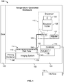
- the system 100 includes an enclosure 102 defining a temperature controlled space 104 that can be sealed via a door 105.
- the space 104 may be approximately or less than 4.5 cubic feet. However, the size of the space 104 may be different depending on the application.
- An imaging system 106, an actuator 108 and a dispenser 110 having a pump 111 are disposed within the space 104.
- the imaging system 106 can be implemented by a LS720 microscope by Etaluma
- the actuator 108 can be implemented by a motorized XY microscope stage by Zaber Technologies
- the pump 111 can be implemented by a 12 V, 25 ⁇ L solenoid pump by The Lee Company.
- different imaging systems, actuators and/or pumps can be used.
- the actuator 108 receives or is otherwise coupled to a well plate 112.
- the well plate 112 has wells 114.
- the actuator 108 is arranged to move the well plate 122 relative to the imaging system 106.
- the imaging system 106 includes an aperture 124 that is sized to obtain image data from one of the wells 114 at a time. Obtaining image data from one of the wells 114 at a time instead of a plurality of the wells 114 at a time increases the quality of the image data obtained.
- the dispenser 110 also includes a reservoir holder 126, an adjuster 127 and an outlet 128.
- the reservoir holder 126 is arranged to carry a reservoir (a container) 130.
- the reservoir 130 can contain a compound 132 used during the assay.
- the pump 111 is fluidly coupled to the reservoir 130 and the outlet 128.
- the pump 111 is arranged to pump the compound 132 from the reservoir 130 through the outlet 128 into one of the wells 114.
- the actuator 108 can position one of the wells 114 relative to the outlet 128 such that the outlet 128 is centered relative to the one of the wells 114.
- the adjuster 127 can be used to change the relative position of the dispenser 110 and, thus, the outlet 128, relative to a selected one of the wells 114 (e.g., the first well).
- the adjuster 127 can be a manual adjuster or an adjuster that is implemented by one or more actuators (e.g., linear actuators).
- the adjuster 127 can move the position of the outlet 128 radially and/or in an x-direction, a y-direction or a z-direction. More generally, the adjuster 127 can adjust the height, the fore-aft position and/or the side-to-side position of the outlet 128.
- the system 100 also includes a controller 134, which can include an on-board controller (as shown in Fig. 1 ) alone or in combination with other controller technology such as a separate computer running dependent on the controller 134 or entirely independent from the controller 134.
- the controller 134 includes an interface 135. As shown, the interface 135 is operatively coupled to the controller 134 and is positioned outside of the enclosure 102 to enable operator accessibility.
- the controller 134 can be used to control the imaging system 106 and the dispenser 110. Controlling the imaging system 106 may include causing the imaging system 106 to obtain image data of a kinetic reaction taking place in one of the wells 114. Controlling the dispenser 110 may include initiating a priming procedure of the pump 111.
- a priming procedure and a calibration procedure can be performed prior to beginning the assay.
- the priming procedure may be initiated, via the controller 134, by providing a substantially constant high signal (TTL high signal) to the pump 111 in response to an input received at the interface 135.
- the input may include a button 144 (See, Fig. 4 ) of the interface 135 being pressed.
- the signal received at the pump 111 may cause the pump 111 to continuously pump the compound 132 in designated increments into an empty priming container 139.
- the designated increments may be 25 microliter ( ⁇ L) increments. However, the increments may be different depending on the application.
- the pump 111 remains in a resting, non-dispensing state. In the resting, non-dispensing state, the pump 111 is ready to automatically perform the assay on the well plate 112.
- the calibration procedure may include using the adjuster 127 to center the outlet 128 relative to a first well 136 of the wells 114.
- the position of the outlet 128 relative to the first well 136 can be verified by the controller 134 and/or by visual inspection. Centering the outlet 128 relative to the first well 136 may ensure that subsequent movement of the well plate 112, via the actuator 108, results in the outlet 128 being positioned in the center of others of the wells 114.
- the door 105 can be closed and the controller 134 can determine if the first well 136 is positioned such that the imaging system 106 can obtain image data of the first well 136.
- the controller 134 may determine the position of the first well 136 in response to receiving a signal (a TTL low signal) from the imaging system 106.
- the signal may be associated with a light of the imaging system 106 turning on.
- the controller 134 may delay for a threshold amount of time and then send a pulse (a signal) to the pump 111 that causes the pump 111 to dispense an amount of the compound 132 into the first well 136.
- the delay may be 5 seconds or another time period.
- the pulse may be a 150 microsecond ( ⁇ s) pulse that causes the pump 111 to dispense 25 ⁇ L of the compound 132. However, the pulse may cause a different amount of the compound 132 to be dispensed.
- the pump 11 may return to the idle state until the next signal is received at the controller 134 by the imaging system 106.
- the controller 134 causes the imaging system 106 to obtain image data of the first well 136.
- the image data may be obtained at a sampling frequency of 10 hertz (Hz) for 20 seconds. However, different sampling frequencies or times can be used.
- the controller 134 (or in some versions a separate computer) causes the actuator 108 to move the well plate 112 to position another one of the wells 114 over the aperture 124. Once in position, the light of the imaging system 106 turns on, the signal is provided to the controller 134 by the imaging system 106 and the process is repeated.
- the controller 134 (or in some versions, a separate computer) causes the actuator 108 to move the well plate 112 to position the next one of the wells 114 adjacent the aperture 124 of the imaging system 106 and the outlet 128 of the dispenser 110 and the process is repeated.
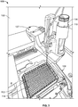
- Figs. 2 and 3 illustrate an example implementation of the system 100 of Fig. 1 .
- the system 100 includes the enclosure 102 having a temperature control 202.
- the temperature control 202 includes a rotatable knob 204.
- the knob 204 can be manually rotated to enable the space 104 to achieve a desired temperature (e.g., between about 4°C and 10°C) to perform the assay.
- the actuator 108 is a motorized XY microscope stage
- the well plate 112 is a 384-well plate
- the adjuster 127 of the dispenser 110 includes a threaded adjuster 138 having a handle 140. Additional details of the dispenser 110 are shown and described in connection with Figs. 5 - 7 below.
- Fig. 4 illustrates an example implementation of the interface 135 of Fig. 1 .
- the interface 135 includes a housing 142 and controls (buttons) 144, 146.
- the controls 144, 146 may be pressed by an operator to initiate, for example, the priming procedure.
- Wires 148 are coupled to the interface 135 to enable communication with the imaging system 106, the actuator 108, the pump 111 and/or the controller 134.
- Figs. 5 - 7 illustrate different views of the dispenser 110 shown in Figs. 2 and 3 .
- the dispenser 110 includes a reservoir holder 126 and a base 150.
- the reservoir holder 126 is movably coupled to the base 150.
- the base 150 carries a rail 152 and the dispenser 110 carries a block 154.
- the block 154 is received about or otherwise interacts with the rail 152 to linearly guide the reservoir holder 126 relative to the base 150.
- the reservoir holder 126 carries the pump 111.
- First tubing (a source tube) 156 extends from the pump 111 into a receptacle 158 of the reservoir holder 126 and second tubing 159 extends from the pump 111 to the outlet 128.
- the outlet 128 is implemented by a dispensing tube.
- a tab 160 extends from the reservoir holder 126.
- the tab 160 defines an aperture 162 through which the outlet 128 extends. An interaction between the tab 160 and the outlet 128 secures the outlet 128 relative to the reservoir holder 126.
- the base 150 includes a first base portion 164 and a second base portion 166.
- the base portions 164, 166 are movably coupled via a fastener 168.
- the first base portion 164 includes a slot 170 through which the fastener 168 extends.
- the slot 170 enables fore-aft adjustment of the first base portion 164 relative to the second base portion 166 and can be used to implement the adjuster 127 of Fig. 1 .
- the second base portion 166 includes opposing walls 172, 174 that define a channel 176.
- the channel 176 receives an end 178 of the first base portion 164.
- An interaction between the walls 172, 174 and the end 178 guide the fore-aft movement of the first base portion 164.
- the second base portion 166 also includes a first sub-base portion 180 and a second sub-base portion 182.
- the sub-base portions 180, 182 are movably coupled via fasteners 184, 186, where the fastener 186 acts as a pivot.
- the first sub-base portion 180 includes a radial slot 188 through which the fastener 184 extends.
- the radial slot 188 enables the first sub-base portion 180, the first base portion 180 and the reservoir holder 126 to move radially relative to the second sub-base portion 182 (left / right; XY tip adjustment).
- the second sub-base portion 182 can be secured to the imaging system 106.
- the radial slot 188 can be used to implement the adjuster 127 of Fig. 1 .
- a fastener 190 extends through the second sub-base portion 182. The fastener 190 can be used to couple the dispenser 110 to the imaging system 106.
- the dispenser 110 includes the threaded adjuster 138 having the handle 140 and an end 192.
- the threaded adjuster 138 extends through the reservoir holder 126 and the end 192 is driven against a surface 194 of the base 150.
- An interaction between the end 192 and the surface 194 adjusts the relative position of the reservoir holder 126 and the base 150 (e.g., height adjustment).
- the threaded adjuster 138 can be used to implement the adjuster 127 of Fig. 1 .
- a lock nut 196 surrounds the threaded adjuster 138.
- the lock nut 196 is tightened against the reservoir holder 126 after the end 192 of the threaded adjuster 138 is driven against the surface 194 of the base 150.
- Fig. 6 also shows the base 150 including cable retention clips 198.
- the retention clips 198 can be used to control cables of, for example, the pump 111.
- a top view of the dispenser 110 is shown illustrating the threaded adjuster 138 and the slots 170, 188 of the adjuster 127.
- the circuit 800 includes a first portion 802 associated with the priming procedure of the pump 111 and a second portion 804 associated with the signal (the trigger) generated by the imaging system 106.
- the circuit 800 includes integrated circuits in the form of 555 timer chips and logic gate chips that receive an input from the imaging system 106. Specifically, the chips are arranged to receive a signal (a transistor-transistor logic (TTL) signal) from the imaging system 106. The signal may be generated when a light of the imaging system 106 turns on.
- TTL transistor-transistor logic
- the circuit 800 is configured to turn the pump 111 on to dispense the compound 132 after a threshold amount of time has lapsed.
- Fig. 9 illustrates a printed circuit board (PCB) 900 including a circuit 902 that can be used to implement the circuit 800 of Fig. 8 and can be used to implement the controller 134 of Fig. 1 .
- the PCB 900 includes a microcontroller that may be implemented by a ATiny25 microcontroller by Microchip Technology Inc.
- the microcontroller executes software to implement the processes disclosed.
- the software ware may include ⁇ Manager by Vale Lab.
- Fig. 10 depicts a flow diagram representing a method 1000 for performing an assay in accordance with the teachings of this disclosure.
- the method 1000 can be executed by the controller 134 shown in Fig. 1 , the circuit 800 shown in Fig. 8 , the circuit 902 shown in Fig. 9 and/or or by any other suitable computing device.
- the actuator 108 positions the first one 136 of the wells 114 of the well plate 112 adjacent the aperture 124 of the imaging system 106.
- the controller 134 causes the dispenser 110 to dispense the compound 132 into the first one 136 of the wells 114. (block 1004). While the dispenser 110 dispenses the compound 132 and/or while a kinetic reaction is taking place, the imaging system 106 obtains image data of the first one 136 of the wells 114. (block 1006). After the image data is obtained, the actuator 108 moves a second one of the wells 114 adjacent the aperture 124.
- the imaging system 106 In response to the second one of the wells 114 being positioned adjacent the aperture 124, the imaging system 106 provides a signal to the controller 134 and the controller 134 causes the dispenser 110 to dispense the compound 132 into the second one of the wells 114. While the dispenser 110 dispenses the compound 132 and/or while the kinetic reaction takes place, the imaging system 106 obtains second image data of the second one of the wells.
- the examples disclosed herein relate to systems for automated cold enclosure assay having a compact/smaller footprint that enables minimal facility modification and/or room modifications (if any). Additionally, the cost of these systems is significantly less as compared to some known cold-room assay (e.g., approximately 1/3 of the cost).
- the example systems can include an enclosure having a temperature controlled space, an imaging system including a microscope, a stage that receives a well plate and a dispenser (a pump mounting system).
- the temperature-controlled space can be implemented by a minifridge and the microscope can include florescence detection capabilities.
- the stage can be implemented by a motorized XY microscope stage and the well plate may be a 384-well optical bottom plate.
- the dispenser can include a reservoir holder, a dispensing head (an injector), a solenoid pump (e.g., 12 V, 25 ⁇ L solenoid pump) and an adjuster.
- the adjuster may be a manual adjuster that enables an outlet of the dispenser to be adjusted in the x-direction, the y-direction, the z-direction and/or radially.
- the reservoir holder can be sized to hold a 50 milliliter (mL) tube for compound storage. However, the reservoir holder can be differently sized to hold a different size container.
- a controller is included.
- the controller includes an interface that may be positioned outside of the enclosure while being electrically coupled to components housed within the enclosure.
- the controller can control the timing of the dispensing of the compound (e.g., liquid) from the dispensing head and the imaging by the imaging system.
- the system can be used to condense a ZnT8 proteoliposome assay, where the assay is performed between 4°C and 10°C and the assay data collection is kinetic.
- other assays can be condensed at the same or different temperatures.
- a user primes the pump using the interface of the controller.
- the pump can continuously dispense a compound of interest in designated increments into an empty container (e.g., an empty 50 mL tube).
- the user can align (center) the outlet of the dispenser with a first one of the wells and can confirm, using feedback from the stage, that the compound was dispensed into the first one of the wells and not into another one of the wells positioned above, below, to the left or to the right of the intended well.
- the position of the outlet over the first one of the wells subsequent movement of the well plate by the stage should result in the outlet of the dispenser being positioned in the center of the respective well.
- the dispenser controllably dispenses the compound in the well to enable image data of the kinetic reaction to be captured by the imaging system.
- the stage moves the well plate to position another one of the wells in alignment with the dispenser and the imaging system. Once aligned, the compound can be dispensed into the corresponding well using the single-dispensing head (pipette) of the dispenser and the imaging system again obtains high-quality image data of the kinetic reaction.
- pipette single-dispensing head
Landscapes
- General Health & Medical Sciences (AREA)
- General Physics & Mathematics (AREA)
- Life Sciences & Earth Sciences (AREA)
- Chemical & Material Sciences (AREA)
- Analytical Chemistry (AREA)
- Biochemistry (AREA)
- Health & Medical Sciences (AREA)
- Immunology (AREA)
- Physics & Mathematics (AREA)
- Pathology (AREA)
- Engineering & Computer Science (AREA)
- Quality & Reliability (AREA)
- Sampling And Sample Adjustment (AREA)
- Automatic Analysis And Handling Materials Therefor (AREA)
- Apparatus Associated With Microorganisms And Enzymes (AREA)
Abstract
Description
- Priority is claimed to
US Provisional Patent Application No. 62/800,372, filed February 1, 2019 US Provisional Patent Application No. 62/801,025, filed February 4, 2019 - The present disclosure relates generally to performing an assay and, more particularly, to methods and systems of performing an assay in a temperature-controlled enclosure.
- Certain biological assays are beneficially performed in reduced-temperature environments such as between 4 degrees and 10 degrees Celsius. Typically such assays are performed manually in a laboratory, for example, that is maintained at the desired temperature. This manual process can be tedious, time-consuming, costly, and less than optimal for the personnel manually handling the materials and performing the assay.
- One aspect of the present disclosure includes a system for performing an assay. The system may include an enclosure, an imaging system, an actuator, a dispenser, and a controller. The enclosure may define a temperature-controlled space. The imaging system may be disposed within the space. The actuator may be disposed within the space to receive a well plate having wells. The actuator further may be to move the well plate relative to the imaging system to enable the imaging system to obtain image data of one of the wells. The dispenser may be disposed within the space, and may include a reservoir holder to receive a reservoir containing a compound, a pump to be fluidly coupled to the reservoir, and an outlet. The pump may be to pump the compound from the reservoir through the outlet into one of the wells. In response to the imaging system being positioned to obtain image data of a first one of the wells, the controller may cause the dispenser to dispense the compound into the first one of the wells while the imaging system obtains the image data.
- Optionally, the outlet comprises a single-well dispensing pipette.
- Optionally, the dispenser further comprises an adjuster to change a relative position of the outlet and the first one of the wells.
- Optionally, the adjuster comprises a manual adjuster.
- Optionally, the reservoir holder carries the pump.
- Optionally, the dispenser further comprises a tab that extends from the reservoir holder, the tab defining an aperture through which the outlet extends to secure the outlet relative to the reservoir holder.
- Optionally, the dispenser further comprises a base, the reservoir holder movably coupled to the base.
- Optionally, the base comprises a rail and the reservoir holder comprises a block that interacts with the rail to linearly guide the reservoir holder relative to the base.
- Optionally, the system further comprises a threaded adjuster that extends through the reservoir holder and includes an end that is driven against a surface of the base to adjust the reservoir holder relative to the base.
- Optionally, the system further comprises a lock nut that surrounds the threaded adjuster, the lock nut to be tightened against the reservoir holder to secure a position of the reservoir holder.
- Optionally, the base comprises a first base portion and a second base portion, the first base portion comprises the rail and the second base portion comprises the surface against which the threaded adjuster is driven, the first base portion comprising a slot through which a fastener extends to couple the first base portion and the second base portion, the slot enabling fore-aft adjustment of the first base portion relative to the second base portion.
- Optionally, the second base portion comprises opposing walls that defines a channel that receives an end of the first base portion to guide the fore-aft movement of the first base portion.
- Optionally, the second base portion comprises a first sub-base portion and a second sub-base portion, the first sub-base portion comprises a radial slot through which a fastener extends to couple the first sub-base portion and the second sub-base portion, the radial slot enabling radial adjustment of the first sub-base portion, the first base portion, and the reservoir holder relative to the second sub-base portion.
- Optionally, the second sub-base portion is coupled to the imaging system via a fastener.
- Optionally, the space is approximately or less than 4.5 cubic feet.
- Optionally, the imaging system comprises a microscope.
- Optionally, the actuator comprises a motorized XY microscope stage.
- Another aspect of the present disclosure relates to a method of performing an assay. The method may include positioning a first one of wells of a well plate adjacent an aperture of an imaging system using an actuator. The method may also include, in response to the first one of the wells being positioned adjacent the aperture, causing a dispenser to dispense a compound into the first one of the wells. The method may also include, while the dispenser dispenses the compound, obtaining image data of the first one of the wells using the imaging system. Optionally, the imaging system, the actuator, and the dispenser are disposed in a temperature-controlled enclosure.
- Optionally, after the image data is obtained, the method further includes moving a second one of the wells adjacent the aperture of the imaging system using the actuator; in response to the second one of the wells being positioned adjacent the aperture, causing the dispenser to dispense the compound into the second one of the wells; and while the dispenser dispenses the compound, obtaining second image data of the second one of the wells.
- Optionally, the method further comprises, prior to positioning the first one of the wells adjacent the aperture, calibrating a position of an outlet of the dispenser relative to the first one of the wells.
- Optionally, the method further comprises, prior to positioning the first one of the wells adjacent the aperture, priming a pump of the dispenser.
- Optionally, obtaining image data of the first one of the wells comprises obtaining image data of the first one of the wells using the imaging system without obtaining image data of others of the wells.
-
-
Fig. 1 illustrates an example system for performing an assay in accordance with the teachings of this disclosure. -
Fig. 2 illustrates an example implementation of the system ofFig. 1 . -
Fig. 3 illustrates a detailed view of the system ofFig. 2 . -
Fig. 4 illustrates an example implementation of the interface ofFig. 1 . -
Figs. 5 - 7 illustrate different views of the dispenser ofFig. 2 . -
Fig. 8 illustrates a schematic diagram of a circuit that can be used to implement the controller ofFig. 1 . -
Fig. 9 illustrates a printed circuit board including a circuit that can be used to implement the circuit ofFig. 8 and the controller ofFig. 1 . -
Fig. 10 is a flow chart representative of machine readable instructions that may be executed to implement the system ofFigs. 1 - 3 . - Although the following text discloses a detailed description of example methods, apparatus and/or articles of manufacture, it should be understood that the legal scope of the property right is defined by the words of the claims set forth at the end of this patent. Accordingly, the following detailed description is to be construed as examples only and does not describe every possible example, as describing every possible example would be impractical, if not impossible. Numerous alternative examples could be implemented, using either current technology or technology developed after the filing date of this patent. It is envisioned that such alternative examples would still fall within the scope of the claims.
- Referring to
Fig. 1 , anexample system 100 for performing an assay in accordance with a first disclosed example is shown. Thesystem 100 includes anenclosure 102 defining a temperature controlledspace 104 that can be sealed via adoor 105. Thespace 104 may be approximately or less than 4.5 cubic feet. However, the size of thespace 104 may be different depending on the application. - An
imaging system 106, anactuator 108 and adispenser 110 having apump 111 are disposed within thespace 104. Theimaging system 106 can be implemented by a LS720 microscope by Etaluma, theactuator 108 can be implemented by a motorized XY microscope stage by Zaber Technologies and thepump 111 can be implemented by a 12 V, 25 µL solenoid pump by The Lee Company. However, different imaging systems, actuators and/or pumps can be used. - The
actuator 108 receives or is otherwise coupled to awell plate 112. Thewell plate 112 haswells 114. Theactuator 108 is arranged to move the well plate 122 relative to theimaging system 106. Theimaging system 106 includes anaperture 124 that is sized to obtain image data from one of thewells 114 at a time. Obtaining image data from one of thewells 114 at a time instead of a plurality of thewells 114 at a time increases the quality of the image data obtained. - The
dispenser 110 also includes areservoir holder 126, anadjuster 127 and anoutlet 128. Thereservoir holder 126 is arranged to carry a reservoir (a container) 130. Thereservoir 130 can contain acompound 132 used during the assay. - The
pump 111 is fluidly coupled to thereservoir 130 and theoutlet 128. Thepump 111 is arranged to pump thecompound 132 from thereservoir 130 through theoutlet 128 into one of thewells 114. Theactuator 108 can position one of thewells 114 relative to theoutlet 128 such that theoutlet 128 is centered relative to the one of thewells 114. - The
adjuster 127 can be used to change the relative position of thedispenser 110 and, thus, theoutlet 128, relative to a selected one of the wells 114 (e.g., the first well). Theadjuster 127 can be a manual adjuster or an adjuster that is implemented by one or more actuators (e.g., linear actuators). Theadjuster 127 can move the position of theoutlet 128 radially and/or in an x-direction, a y-direction or a z-direction. More generally, theadjuster 127 can adjust the height, the fore-aft position and/or the side-to-side position of theoutlet 128. - The
system 100 also includes acontroller 134, which can include an on-board controller (as shown inFig. 1 ) alone or in combination with other controller technology such as a separate computer running dependent on thecontroller 134 or entirely independent from thecontroller 134. Thecontroller 134 includes aninterface 135. As shown, theinterface 135 is operatively coupled to thecontroller 134 and is positioned outside of theenclosure 102 to enable operator accessibility. Thecontroller 134 can be used to control theimaging system 106 and thedispenser 110. Controlling theimaging system 106 may include causing theimaging system 106 to obtain image data of a kinetic reaction taking place in one of thewells 114. Controlling thedispenser 110 may include initiating a priming procedure of thepump 111. - In practice, prior to beginning the assay, a priming procedure and a calibration procedure can be performed. The priming procedure may be initiated, via the
controller 134, by providing a substantially constant high signal (TTL high signal) to thepump 111 in response to an input received at theinterface 135. The input may include a button 144 (See,Fig. 4 ) of theinterface 135 being pressed. - The signal received at the
pump 111 may cause thepump 111 to continuously pump thecompound 132 in designated increments into an empty priming container 139. The designated increments may be 25 microliter (µL) increments. However, the increments may be different depending on the application. After the priming procedure is complete, thepump 111 remains in a resting, non-dispensing state. In the resting, non-dispensing state, thepump 111 is ready to automatically perform the assay on thewell plate 112. - The calibration procedure may include using the
adjuster 127 to center theoutlet 128 relative to a first well 136 of thewells 114. The position of theoutlet 128 relative to the first well 136 can be verified by thecontroller 134 and/or by visual inspection. Centering theoutlet 128 relative to the first well 136 may ensure that subsequent movement of thewell plate 112, via theactuator 108, results in theoutlet 128 being positioned in the center of others of thewells 114. - After the priming procedure and the calibration procedure are complete, the
door 105 can be closed and thecontroller 134 can determine if thefirst well 136 is positioned such that theimaging system 106 can obtain image data of thefirst well 136. Thecontroller 134 may determine the position of the first well 136 in response to receiving a signal (a TTL low signal) from theimaging system 106. The signal may be associated with a light of theimaging system 106 turning on. - In response to the signal, the
controller 134 may delay for a threshold amount of time and then send a pulse (a signal) to thepump 111 that causes thepump 111 to dispense an amount of thecompound 132 into thefirst well 136. The delay may be 5 seconds or another time period. The pulse may be a 150 microsecond (µs) pulse that causes thepump 111 to dispense 25 µL of thecompound 132. However, the pulse may cause a different amount of thecompound 132 to be dispensed. After the compound is dispensed, the pump 11 may return to the idle state until the next signal is received at thecontroller 134 by theimaging system 106. - While the kinetic reaction is occurring within the
first well 136, thecontroller 134 causes theimaging system 106 to obtain image data of thefirst well 136. The image data (images) may be obtained at a sampling frequency of 10 hertz (Hz) for 20 seconds. However, different sampling frequencies or times can be used. - After the image data is obtained from the
first well 136, the controller 134 (or in some versions a separate computer) causes theactuator 108 to move thewell plate 112 to position another one of thewells 114 over theaperture 124. Once in position, the light of theimaging system 106 turns on, the signal is provided to thecontroller 134 by theimaging system 106 and the process is repeated. After the image data is obtained, the controller 134 (or in some versions, a separate computer) causes theactuator 108 to move thewell plate 112 to position the next one of thewells 114 adjacent theaperture 124 of theimaging system 106 and theoutlet 128 of thedispenser 110 and the process is repeated. -
Figs. 2 and3 illustrate an example implementation of thesystem 100 ofFig. 1 . Thesystem 100 includes theenclosure 102 having a temperature control 202. The temperature control 202 includes a rotatable knob 204. The knob 204 can be manually rotated to enable thespace 104 to achieve a desired temperature (e.g., between about 4°C and 10°C) to perform the assay. - In the
example system 100 ofFig. 2 , theactuator 108 is a motorized XY microscope stage, thewell plate 112 is a 384-well plate and theadjuster 127 of thedispenser 110 includes a threadedadjuster 138 having ahandle 140. Additional details of thedispenser 110 are shown and described in connection withFigs. 5 - 7 below. -
Fig. 4 illustrates an example implementation of theinterface 135 ofFig. 1 . Theinterface 135 includes ahousing 142 and controls (buttons) 144, 146. Thecontrols Wires 148 are coupled to theinterface 135 to enable communication with theimaging system 106, theactuator 108, thepump 111 and/or thecontroller 134. -
Figs. 5 - 7 illustrate different views of thedispenser 110 shown inFigs. 2 and3 . - Referring to
Fig. 5 , thedispenser 110 includes areservoir holder 126 and a base 150. Thereservoir holder 126 is movably coupled to the base 150. Specifically, the base 150 carries a rail 152 and thedispenser 110 carries a block 154. The block 154 is received about or otherwise interacts with the rail 152 to linearly guide thereservoir holder 126 relative to the base 150. - The
reservoir holder 126 carries thepump 111. First tubing (a source tube) 156 extends from thepump 111 into a receptacle 158 of thereservoir holder 126 and second tubing 159 extends from thepump 111 to theoutlet 128. Theoutlet 128 is implemented by a dispensing tube. - A tab 160 extends from the
reservoir holder 126. The tab 160 defines an aperture 162 through which theoutlet 128 extends. An interaction between the tab 160 and theoutlet 128 secures theoutlet 128 relative to thereservoir holder 126. - The base 150 includes a first base portion 164 and a second base portion 166. The base portions 164, 166 are movably coupled via a fastener 168. The first base portion 164 includes a
slot 170 through which the fastener 168 extends. Theslot 170 enables fore-aft adjustment of the first base portion 164 relative to the second base portion 166 and can be used to implement theadjuster 127 ofFig. 1 . - The second base portion 166 includes opposing walls 172, 174 that define a channel 176. The channel 176 receives an end 178 of the first base portion 164. An interaction between the walls 172, 174 and the end 178 guide the fore-aft movement of the first base portion 164.
- The second base portion 166 also includes a first sub-base portion 180 and a second sub-base portion 182. The sub-base portions 180, 182 are movably coupled via fasteners 184, 186, where the fastener 186 acts as a pivot. The first sub-base portion 180 includes a
radial slot 188 through which the fastener 184 extends. Theradial slot 188 enables the first sub-base portion 180, the first base portion 180 and thereservoir holder 126 to move radially relative to the second sub-base portion 182 (left / right; XY tip adjustment). - The second sub-base portion 182 can be secured to the
imaging system 106. Theradial slot 188 can be used to implement theadjuster 127 ofFig. 1 . A fastener 190 extends through the second sub-base portion 182. The fastener 190 can be used to couple thedispenser 110 to theimaging system 106. - Referring to
Fig. 6 , another isometric view of thedispenser 110 is shown. Thedispenser 110 includes the threadedadjuster 138 having thehandle 140 and an end 192. The threadedadjuster 138 extends through thereservoir holder 126 and the end 192 is driven against a surface 194 of the base 150. An interaction between the end 192 and the surface 194 adjusts the relative position of thereservoir holder 126 and the base 150 (e.g., height adjustment). Thus, the threadedadjuster 138 can be used to implement theadjuster 127 ofFig. 1 . - A lock nut 196 surrounds the threaded
adjuster 138. The lock nut 196 is tightened against thereservoir holder 126 after the end 192 of the threadedadjuster 138 is driven against the surface 194 of the base 150. An interaction between the lock nut 196 and the threadedadjuster 138 and thereservoir holder 126 secures thereservoir holder 126 in place.Fig. 6 also shows the base 150 including cable retention clips 198. The retention clips 198 can be used to control cables of, for example, thepump 111. - Referring to
Fig. 7 , a top view of thedispenser 110 is shown illustrating the threadedadjuster 138 and theslots adjuster 127. - Referring to
Fig. 8 , a schematic diagram of acircuit 800 that might be used to try and implement thecontroller 134 ofFig. 1 is shown. Thecircuit 800 includes afirst portion 802 associated with the priming procedure of thepump 111 and asecond portion 804 associated with the signal (the trigger) generated by theimaging system 106. Thecircuit 800 includes integrated circuits in the form of 555 timer chips and logic gate chips that receive an input from theimaging system 106. Specifically, the chips are arranged to receive a signal (a transistor-transistor logic (TTL) signal) from theimaging system 106. The signal may be generated when a light of theimaging system 106 turns on. In response to the signal received, thecircuit 800 is configured to turn thepump 111 on to dispense thecompound 132 after a threshold amount of time has lapsed. -
Fig. 9 illustrates a printed circuit board (PCB) 900 including acircuit 902 that can be used to implement thecircuit 800 ofFig. 8 and can be used to implement thecontroller 134 ofFig. 1 . ThePCB 900 includes a microcontroller that may be implemented by a ATiny25 microcontroller by Microchip Technology Inc. The microcontroller executes software to implement the processes disclosed. The software ware may include µManager by Vale Lab. -
Fig. 10 depicts a flow diagram representing amethod 1000 for performing an assay in accordance with the teachings of this disclosure. Themethod 1000 can be executed by thecontroller 134 shown inFig. 1 , thecircuit 800 shown inFig. 8 , thecircuit 902 shown inFig. 9 and/or or by any other suitable computing device. - At
block 1002, the actuator 108 positions the first one 136 of thewells 114 of thewell plate 112 adjacent theaperture 124 of theimaging system 106. In response to the first one 136 of thewells 114 being positioned adjacent theaperture 124, thecontroller 134 causes thedispenser 110 to dispense thecompound 132 into the first one 136 of thewells 114. (block 1004). While thedispenser 110 dispenses thecompound 132 and/or while a kinetic reaction is taking place, theimaging system 106 obtains image data of the first one 136 of thewells 114. (block 1006). After the image data is obtained, theactuator 108 moves a second one of thewells 114 adjacent theaperture 124. In response to the second one of thewells 114 being positioned adjacent theaperture 124, theimaging system 106 provides a signal to thecontroller 134 and thecontroller 134 causes thedispenser 110 to dispense thecompound 132 into the second one of thewells 114. While thedispenser 110 dispenses thecompound 132 and/or while the kinetic reaction takes place, theimaging system 106 obtains second image data of the second one of the wells. - The examples disclosed herein relate to systems for automated cold enclosure assay having a compact/smaller footprint that enables minimal facility modification and/or room modifications (if any). Additionally, the cost of these systems is significantly less as compared to some known cold-room assay (e.g., approximately 1/3 of the cost).
- The example systems can include an enclosure having a temperature controlled space, an imaging system including a microscope, a stage that receives a well plate and a dispenser (a pump mounting system). The temperature-controlled space can be implemented by a minifridge and the microscope can include florescence detection capabilities. The stage can be implemented by a motorized XY microscope stage and the well plate may be a 384-well optical bottom plate.
- The dispenser can include a reservoir holder, a dispensing head (an injector), a solenoid pump (e.g., 12 V, 25 µL solenoid pump) and an adjuster. The adjuster may be a manual adjuster that enables an outlet of the dispenser to be adjusted in the x-direction, the y-direction, the z-direction and/or radially. The reservoir holder can be sized to hold a 50 milliliter (mL) tube for compound storage. However, the reservoir holder can be differently sized to hold a different size container.
- To enable operator control of the system, a controller is included. The controller includes an interface that may be positioned outside of the enclosure while being electrically coupled to components housed within the enclosure. The controller can control the timing of the dispensing of the compound (e.g., liquid) from the dispensing head and the imaging by the imaging system.
- In practice, the system can be used to condense a ZnT8 proteoliposome assay, where the assay is performed between 4°C and 10°C and the assay data collection is kinetic. However, other assays can be condensed at the same or different temperatures. To initiate a procedure, a user primes the pump using the interface of the controller. During the priming procedure, the pump can continuously dispense a compound of interest in designated increments into an empty container (e.g., an empty 50 mL tube). Using the adjuster of the dispenser, the user can align (center) the outlet of the dispenser with a first one of the wells and can confirm, using feedback from the stage, that the compound was dispensed into the first one of the wells and not into another one of the wells positioned above, below, to the left or to the right of the intended well. After calibrating the position of the outlet over the first one of the wells, subsequent movement of the well plate by the stage should result in the outlet of the dispenser being positioned in the center of the respective well.
- When performing an assay, the dispenser controllably dispenses the compound in the well to enable image data of the kinetic reaction to be captured by the imaging system. After the analysis is performed on one of the wells, the stage moves the well plate to position another one of the wells in alignment with the dispenser and the imaging system. Once aligned, the compound can be dispensed into the corresponding well using the single-dispensing head (pipette) of the dispenser and the imaging system again obtains high-quality image data of the kinetic reaction.
- Further, while several examples have been disclosed herein, any features from any examples may be combined with or replaced by other features from other examples. Moreover, while several examples have been disclosed herein, changes may be made to the disclosed examples without departing from the scope of the claims.
Claims (15)
- A system for performing an assay, comprising:an enclosure defining a temperature-controlled space;an imaging system disposed within the space;an actuator disposed within the space, the actuator to receive a well plate having wells, the actuator to move the well plate relative to the imaging system to enable the imaging system to obtain image data of one of the wells;a dispenser disposed within the space, the dispenser comprising:a reservoir holder to receive a reservoir containing a compound;a pump to be fluidly coupled to the reservoir; andan outlet, the pump to pump the compound from the reservoir through the outlet into one of the wells; anda controller, in response to the imaging system being positioned to obtain image data of a first one of the wells, the controller to cause the dispenser to dispense the compound into the first one of the wells while the imaging system obtains the image data.
- The system of claim 1, wherein the outlet comprises a single-well dispensing pipette and/or the reservoir holder carries the pump.
- The system of claim 1 or claim 2, wherein the dispenser further comprises an adjuster to change a relative position of the outlet and the first one of the wells, wherein the adjuster optionally comprises a manual adjuster.
- The system of any one of claims 1 to 3, wherein the dispenser further comprises a tab that extends from the reservoir holder, the tab defining an aperture through which the outlet extends to secure the outlet relative to the reservoir holder.
- The system of claim 4, wherein the dispenser further comprises a base, the reservoir holder movably coupled to the base, wherein the base optionally comprises a rail and the reservoir holder comprises a block that interacts with the rail to linearly guide the reservoir holder relative to the base.
- The system of claim 5, further comprising a threaded adjuster that extends through the reservoir holder and includes an end that is driven against a surface of the base to adjust the reservoir holder relative to the base.
- The system of claim 6, further comprising a lock nut that surrounds the threaded adjuster, the lock nut to be tightened against the reservoir holder to secure a position of the reservoir holder.
- The system of claim 6 or claim 7, wherein the base comprises a first base portion and a second base portion, the first base portion comprises the rail and the second base portion comprises the surface against which the threaded adjuster is driven, the first base portion comprising a slot through which a fastener extends to couple the first base portion and the second base portion, the slot enabling fore-aft adjustment of the first base portion relative to the second base portion, wherein the second base portion optionally comprises one of (a) or (b):(a) opposing walls that defines a channel that receives an end of the first base portion to guide the fore-aft movement of the first base portion,(b) a first sub-base portion and a second sub-base portion, the first sub-base portion comprises a radial slot through which a fastener extends to couple the first sub-base portion and the second sub-base portion, the radial slot enabling radial adjustment of the first sub-base portion, the first base portion, and the reservoir holder relative to the second sub-base portion.
- The system of claim 8, wherein the second sub-base portion is coupled to the imaging system via a fastener.
- The system of any one of claims 1 to 9, comprising at least one of the following (a) through (c):(a) the space is approximately or less than 4.5 cubic feet,(b) the imaging system comprises a microscope, and/or(c) the actuator comprises a motorized XY microscope stage.
- A method of performing an assay, comprising:positioning a first one of wells of a well plate adjacent an aperture of an imaging system using an actuator;in response to the first one of the wells being positioned adjacent the aperture, causing a dispenser to dispense a compound into the first one of the wells; andwhile the dispenser dispenses the compound, obtaining image data of the first one of the wells using the imaging system,wherein the imaging system, the actuator, and the dispenser are disposed in a temperature-controlled enclosure.
- The method of claim 11, after the image data is obtained, further comprising:moving a second one of the wells adjacent the aperture of the imaging system using the actuator;in response to the second one of the wells being positioned adjacent the aperture, causing the dispenser to dispense the compound into the second one of the wells; andwhile the dispenser dispenses the compound, obtaining second image data of the second one of the wells.
- The method of claim 11 or claim 12, further comprising, prior to positioning the first one of the wells adjacent the aperture, calibrating a position of an outlet of the dispenser relative to the first one of the wells.
- The method of any one of claims 11 to 13, further comprising, prior to positioning the first one of the wells adjacent the aperture, priming a pump of the dispenser.
- The method of any one of claims 11 to 14, wherein obtaining image data of the first one of the wells comprises obtaining image data of the first one of the wells using the imaging system without obtaining image data of others of the wells.
Applications Claiming Priority (2)
| Application Number | Priority Date | Filing Date | Title |
|---|---|---|---|
| US201962800372P | 2019-02-01 | 2019-02-01 | |
| US201962801025P | 2019-02-04 | 2019-02-04 |
Publications (1)
| Publication Number | Publication Date |
|---|---|
| EP3690511A1 true EP3690511A1 (en) | 2020-08-05 |
Family
ID=69411367
Family Applications (1)
| Application Number | Title | Priority Date | Filing Date |
|---|---|---|---|
| EP20154680.1A Pending EP3690511A1 (en) | 2019-02-01 | 2020-01-30 | Microscope for imaging wells comprising a dispenser and temperature-controlled enclosure |
Country Status (3)
| Country | Link |
|---|---|
| US (1) | US11733251B2 (en) |
| EP (1) | EP3690511A1 (en) |
| MA (1) | MA52592A (en) |
Families Citing this family (1)
| Publication number | Priority date | Publication date | Assignee | Title |
|---|---|---|---|---|
| WO2022051840A1 (en) * | 2020-09-08 | 2022-03-17 | Nicoya Lifesciences, Inc. | Pipette dispenser system and method |
Citations (5)
| Publication number | Priority date | Publication date | Assignee | Title |
|---|---|---|---|---|
| US6558623B1 (en) * | 2000-07-06 | 2003-05-06 | Robodesign International, Inc. | Microarray dispensing with real-time verification and inspection |
| US20040197926A1 (en) * | 2003-01-21 | 2004-10-07 | Markus Schuerf | Device and method for observing reactions in samples |
| US20060275847A1 (en) * | 2002-05-14 | 2006-12-07 | Goodyer Ian D | Method for assessing biofilms |
| JP2007228863A (en) * | 2006-02-28 | 2007-09-13 | Olympus Corp | Apparatus for detecting closed type reaction |
| WO2018033600A1 (en) * | 2016-08-19 | 2018-02-22 | Tecan Trading Ag | Measuring device with injector and spray protection |
Family Cites Families (2)
| Publication number | Priority date | Publication date | Assignee | Title |
|---|---|---|---|---|
| US9810704B2 (en) * | 2013-02-18 | 2017-11-07 | Theranos, Inc. | Systems and methods for multi-analysis |
| EP2805143A4 (en) * | 2012-01-17 | 2015-08-12 | Scripps Research Inst | APPARATUS AND METHOD FOR PREPARING SAMPLES FOR ELECTRON MICROSCOPY |
-
2020
- 2020-01-14 US US16/741,808 patent/US11733251B2/en active Active
- 2020-01-30 MA MA052592A patent/MA52592A/en unknown
- 2020-01-30 EP EP20154680.1A patent/EP3690511A1/en active Pending
Patent Citations (5)
| Publication number | Priority date | Publication date | Assignee | Title |
|---|---|---|---|---|
| US6558623B1 (en) * | 2000-07-06 | 2003-05-06 | Robodesign International, Inc. | Microarray dispensing with real-time verification and inspection |
| US20060275847A1 (en) * | 2002-05-14 | 2006-12-07 | Goodyer Ian D | Method for assessing biofilms |
| US20040197926A1 (en) * | 2003-01-21 | 2004-10-07 | Markus Schuerf | Device and method for observing reactions in samples |
| JP2007228863A (en) * | 2006-02-28 | 2007-09-13 | Olympus Corp | Apparatus for detecting closed type reaction |
| WO2018033600A1 (en) * | 2016-08-19 | 2018-02-22 | Tecan Trading Ag | Measuring device with injector and spray protection |
Also Published As
| Publication number | Publication date |
|---|---|
| US20200249248A1 (en) | 2020-08-06 |
| US11733251B2 (en) | 2023-08-22 |
| MA52592A (en) | 2021-03-17 |
Similar Documents
| Publication | Publication Date | Title |
|---|---|---|
| US11619643B2 (en) | Arrangement for preparing a plurality of samples for an analytical method | |
| EP3651905B1 (en) | Automatic analyzer and method for carrying out chemical, biochemical and/or immunochemical analyses | |
| US7823535B2 (en) | Liquid portioning method and device | |
| US6694197B1 (en) | Single channel reformatter | |
| US20180364269A1 (en) | Device for automatic sampling | |
| EP2028494A2 (en) | Sample analyzer and sample analyzing method | |
| US10613109B2 (en) | Dispensing apparatus | |
| EP0712000A2 (en) | Incubation chamber in automated immunoassay analyser | |
| US8354078B2 (en) | Liquid aspirating tube, liquid dispensing apparatus and liquid dispensing method | |
| US20140004020A1 (en) | Stand for use with affinity capture | |
| US20020104389A1 (en) | Automated liquid handling device | |
| CN1930479A (en) | Device for supplying whole blood analyser | |
| US20030013199A1 (en) | Method and instrument for automated analysis of fluid-based processing systems | |
| CN109072155A (en) | Nucleic acid analyzer and method for nucleic acid analysis | |
| US11733251B2 (en) | Methods and systems of performing an assay | |
| JP2020034513A (en) | Conveyance system, specimen analysis device, specimen rack, and conveyance regulation method | |
| CN108884430A (en) | Nucleic acid analysis device and nucleic acid analysis method | |
| US20190018029A1 (en) | Automated Analysis Device and Automated Analysis Method | |
| US20050032241A1 (en) | Reagent dispenser and dispensing method | |
| US20170315047A1 (en) | Pretreatment apparatus and sample analyzer | |
| CN105659096A (en) | Sample preparation workstation | |
| US11906406B2 (en) | Automatic analyzer and analysis method | |
| WO2008050396A1 (en) | Analyzer | |
| JP7843779B2 (en) | Taylor cone emitter device automated handling apparatus, Taylor cone emitter device automated handling system, and method for analyzing a sample | |
| EP4495605A1 (en) | Testing device |
Legal Events
| Date | Code | Title | Description |
|---|---|---|---|
| PUAI | Public reference made under article 153(3) epc to a published international application that has entered the european phase |
Free format text: ORIGINAL CODE: 0009012 |
|
| STAA | Information on the status of an ep patent application or granted ep patent |
Free format text: STATUS: THE APPLICATION HAS BEEN PUBLISHED |
|
| AK | Designated contracting states |
Kind code of ref document: A1 Designated state(s): AL AT BE BG CH CY CZ DE DK EE ES FI FR GB GR HR HU IE IS IT LI LT LU LV MC MK MT NL NO PL PT RO RS SE SI SK SM TR |
|
| AX | Request for extension of the european patent |
Extension state: BA ME |
|
| STAA | Information on the status of an ep patent application or granted ep patent |
Free format text: STATUS: REQUEST FOR EXAMINATION WAS MADE |
|
| 17P | Request for examination filed |
Effective date: 20210204 |
|
| RAV | Requested validation state of the european patent: fee paid |
Extension state: MA Effective date: 20210204 Extension state: TN Effective date: 20210204 |
|
| RAX | Requested extension states of the european patent have changed |
Extension state: ME Payment date: 20210204 Extension state: BA Payment date: 20210204 |
|
| RBV | Designated contracting states (corrected) |
Designated state(s): AL AT BE BG CH CY CZ DE DK EE ES FI FR GB GR HR HU IE IS IT LI LT LU LV MC MK MT NL NO PL PT RO RS SE SI SK SM TR |
|
| STAA | Information on the status of an ep patent application or granted ep patent |
Free format text: STATUS: EXAMINATION IS IN PROGRESS |
|
| 17Q | First examination report despatched |
Effective date: 20211223 |
|
| P01 | Opt-out of the competence of the unified patent court (upc) registered |
Effective date: 20230516 |
|
| RAP3 | Party data changed (applicant data changed or rights of an application transferred) |
Owner name: AMGEN INC. |