EP3690477B1 - Method and device for inter-vehicle communication via radar system - Google Patents
Method and device for inter-vehicle communication via radar system Download PDFInfo
- Publication number
- EP3690477B1 EP3690477B1 EP20153076.3A EP20153076A EP3690477B1 EP 3690477 B1 EP3690477 B1 EP 3690477B1 EP 20153076 A EP20153076 A EP 20153076A EP 3690477 B1 EP3690477 B1 EP 3690477B1
- Authority
- EP
- European Patent Office
- Prior art keywords
- information
- signals
- receiving
- computing device
- transmitting
- Prior art date
- Legal status (The legal status is an assumption and is not a legal conclusion. Google has not performed a legal analysis and makes no representation as to the accuracy of the status listed.)
- Active
Links
Images


Classifications
-
- G—PHYSICS
- G01—MEASURING; TESTING
- G01S—RADIO DIRECTION-FINDING; RADIO NAVIGATION; DETERMINING DISTANCE OR VELOCITY BY USE OF RADIO WAVES; LOCATING OR PRESENCE-DETECTING BY USE OF THE REFLECTION OR RERADIATION OF RADIO WAVES; ANALOGOUS ARRANGEMENTS USING OTHER WAVES
- G01S13/00—Systems using the reflection or reradiation of radio waves, e.g. radar systems; Analogous systems using reflection or reradiation of waves whose nature or wavelength is irrelevant or unspecified
- G01S13/02—Systems using reflection of radio waves, e.g. primary radar systems; Analogous systems
- G01S13/06—Systems determining position data of a target
- G01S13/08—Systems for measuring distance only
- G01S13/32—Systems for measuring distance only using transmission of continuous waves, whether amplitude-, frequency-, or phase-modulated, or unmodulated
-
- G—PHYSICS
- G01—MEASURING; TESTING
- G01S—RADIO DIRECTION-FINDING; RADIO NAVIGATION; DETERMINING DISTANCE OR VELOCITY BY USE OF RADIO WAVES; LOCATING OR PRESENCE-DETECTING BY USE OF THE REFLECTION OR RERADIATION OF RADIO WAVES; ANALOGOUS ARRANGEMENTS USING OTHER WAVES
- G01S13/00—Systems using the reflection or reradiation of radio waves, e.g. radar systems; Analogous systems using reflection or reradiation of waves whose nature or wavelength is irrelevant or unspecified
- G01S13/02—Systems using reflection of radio waves, e.g. primary radar systems; Analogous systems
- G01S13/04—Systems determining presence of a target
-
- H—ELECTRICITY
- H04—ELECTRIC COMMUNICATION TECHNIQUE
- H04W—WIRELESS COMMUNICATION NETWORKS
- H04W4/00—Services specially adapted for wireless communication networks; Facilities therefor
- H04W4/30—Services specially adapted for particular environments, situations or purposes
- H04W4/40—Services specially adapted for particular environments, situations or purposes for vehicles, e.g. vehicle-to-pedestrians [V2P]
- H04W4/46—Services specially adapted for particular environments, situations or purposes for vehicles, e.g. vehicle-to-pedestrians [V2P] for vehicle-to-vehicle communication [V2V]
-
- B—PERFORMING OPERATIONS; TRANSPORTING
- B60—VEHICLES IN GENERAL
- B60W—CONJOINT CONTROL OF VEHICLE SUB-UNITS OF DIFFERENT TYPE OR DIFFERENT FUNCTION; CONTROL SYSTEMS SPECIALLY ADAPTED FOR HYBRID VEHICLES; ROAD VEHICLE DRIVE CONTROL SYSTEMS FOR PURPOSES NOT RELATED TO THE CONTROL OF A PARTICULAR SUB-UNIT
- B60W40/00—Estimation or calculation of non-directly measurable driving parameters for road vehicle drive control systems not related to the control of a particular sub unit, e.g. by using mathematical models
- B60W40/02—Estimation or calculation of non-directly measurable driving parameters for road vehicle drive control systems not related to the control of a particular sub unit, e.g. by using mathematical models related to ambient conditions
-
- B—PERFORMING OPERATIONS; TRANSPORTING
- B60—VEHICLES IN GENERAL
- B60W—CONJOINT CONTROL OF VEHICLE SUB-UNITS OF DIFFERENT TYPE OR DIFFERENT FUNCTION; CONTROL SYSTEMS SPECIALLY ADAPTED FOR HYBRID VEHICLES; ROAD VEHICLE DRIVE CONTROL SYSTEMS FOR PURPOSES NOT RELATED TO THE CONTROL OF A PARTICULAR SUB-UNIT
- B60W60/00—Drive control systems specially adapted for autonomous road vehicles
- B60W60/001—Planning or execution of driving tasks
-
- G—PHYSICS
- G01—MEASURING; TESTING
- G01S—RADIO DIRECTION-FINDING; RADIO NAVIGATION; DETERMINING DISTANCE OR VELOCITY BY USE OF RADIO WAVES; LOCATING OR PRESENCE-DETECTING BY USE OF THE REFLECTION OR RERADIATION OF RADIO WAVES; ANALOGOUS ARRANGEMENTS USING OTHER WAVES
- G01S13/00—Systems using the reflection or reradiation of radio waves, e.g. radar systems; Analogous systems using reflection or reradiation of waves whose nature or wavelength is irrelevant or unspecified
- G01S13/02—Systems using reflection of radio waves, e.g. primary radar systems; Analogous systems
- G01S13/06—Systems determining position data of a target
-
- G—PHYSICS
- G01—MEASURING; TESTING
- G01S—RADIO DIRECTION-FINDING; RADIO NAVIGATION; DETERMINING DISTANCE OR VELOCITY BY USE OF RADIO WAVES; LOCATING OR PRESENCE-DETECTING BY USE OF THE REFLECTION OR RERADIATION OF RADIO WAVES; ANALOGOUS ARRANGEMENTS USING OTHER WAVES
- G01S13/00—Systems using the reflection or reradiation of radio waves, e.g. radar systems; Analogous systems using reflection or reradiation of waves whose nature or wavelength is irrelevant or unspecified
- G01S13/02—Systems using reflection of radio waves, e.g. primary radar systems; Analogous systems
- G01S13/06—Systems determining position data of a target
- G01S13/42—Simultaneous measurement of distance and other co-ordinates
-
- G—PHYSICS
- G01—MEASURING; TESTING
- G01S—RADIO DIRECTION-FINDING; RADIO NAVIGATION; DETERMINING DISTANCE OR VELOCITY BY USE OF RADIO WAVES; LOCATING OR PRESENCE-DETECTING BY USE OF THE REFLECTION OR RERADIATION OF RADIO WAVES; ANALOGOUS ARRANGEMENTS USING OTHER WAVES
- G01S13/00—Systems using the reflection or reradiation of radio waves, e.g. radar systems; Analogous systems using reflection or reradiation of waves whose nature or wavelength is irrelevant or unspecified
- G01S13/02—Systems using reflection of radio waves, e.g. primary radar systems; Analogous systems
- G01S13/50—Systems of measurement based on relative movement of target
- G01S13/58—Velocity or trajectory determination systems; Sense-of-movement determination systems
-
- G—PHYSICS
- G01—MEASURING; TESTING
- G01S—RADIO DIRECTION-FINDING; RADIO NAVIGATION; DETERMINING DISTANCE OR VELOCITY BY USE OF RADIO WAVES; LOCATING OR PRESENCE-DETECTING BY USE OF THE REFLECTION OR RERADIATION OF RADIO WAVES; ANALOGOUS ARRANGEMENTS USING OTHER WAVES
- G01S13/00—Systems using the reflection or reradiation of radio waves, e.g. radar systems; Analogous systems using reflection or reradiation of waves whose nature or wavelength is irrelevant or unspecified
- G01S13/74—Systems using reradiation of radio waves, e.g. secondary radar systems; Analogous systems
- G01S13/82—Systems using reradiation of radio waves, e.g. secondary radar systems; Analogous systems wherein continuous-type signals are transmitted
- G01S13/825—Systems using reradiation of radio waves, e.g. secondary radar systems; Analogous systems wherein continuous-type signals are transmitted with exchange of information between interrogator and responder
-
- G—PHYSICS
- G01—MEASURING; TESTING
- G01S—RADIO DIRECTION-FINDING; RADIO NAVIGATION; DETERMINING DISTANCE OR VELOCITY BY USE OF RADIO WAVES; LOCATING OR PRESENCE-DETECTING BY USE OF THE REFLECTION OR RERADIATION OF RADIO WAVES; ANALOGOUS ARRANGEMENTS USING OTHER WAVES
- G01S13/00—Systems using the reflection or reradiation of radio waves, e.g. radar systems; Analogous systems using reflection or reradiation of waves whose nature or wavelength is irrelevant or unspecified
- G01S13/86—Combinations of radar systems with non-radar systems, e.g. sonar, direction finder
-
- G—PHYSICS
- G01—MEASURING; TESTING
- G01S—RADIO DIRECTION-FINDING; RADIO NAVIGATION; DETERMINING DISTANCE OR VELOCITY BY USE OF RADIO WAVES; LOCATING OR PRESENCE-DETECTING BY USE OF THE REFLECTION OR RERADIATION OF RADIO WAVES; ANALOGOUS ARRANGEMENTS USING OTHER WAVES
- G01S13/00—Systems using the reflection or reradiation of radio waves, e.g. radar systems; Analogous systems using reflection or reradiation of waves whose nature or wavelength is irrelevant or unspecified
- G01S13/88—Radar or analogous systems specially adapted for specific applications
-
- G—PHYSICS
- G01—MEASURING; TESTING
- G01S—RADIO DIRECTION-FINDING; RADIO NAVIGATION; DETERMINING DISTANCE OR VELOCITY BY USE OF RADIO WAVES; LOCATING OR PRESENCE-DETECTING BY USE OF THE REFLECTION OR RERADIATION OF RADIO WAVES; ANALOGOUS ARRANGEMENTS USING OTHER WAVES
- G01S13/00—Systems using the reflection or reradiation of radio waves, e.g. radar systems; Analogous systems using reflection or reradiation of waves whose nature or wavelength is irrelevant or unspecified
- G01S13/88—Radar or analogous systems specially adapted for specific applications
- G01S13/93—Radar or analogous systems specially adapted for specific applications for anti-collision purposes
- G01S13/931—Radar or analogous systems specially adapted for specific applications for anti-collision purposes of land vehicles
-
- G—PHYSICS
- G05—CONTROLLING; REGULATING
- G05D—SYSTEMS FOR CONTROLLING OR REGULATING NON-ELECTRIC VARIABLES
- G05D1/00—Control of position, course, altitude or attitude of land, water, air or space vehicles, e.g. using automatic pilots
- G05D1/0011—Control of position, course, altitude or attitude of land, water, air or space vehicles, e.g. using automatic pilots associated with a remote control arrangement
- G05D1/0022—Control of position, course, altitude or attitude of land, water, air or space vehicles, e.g. using automatic pilots associated with a remote control arrangement characterised by the communication link
-
- B—PERFORMING OPERATIONS; TRANSPORTING
- B60—VEHICLES IN GENERAL
- B60W—CONJOINT CONTROL OF VEHICLE SUB-UNITS OF DIFFERENT TYPE OR DIFFERENT FUNCTION; CONTROL SYSTEMS SPECIALLY ADAPTED FOR HYBRID VEHICLES; ROAD VEHICLE DRIVE CONTROL SYSTEMS FOR PURPOSES NOT RELATED TO THE CONTROL OF A PARTICULAR SUB-UNIT
- B60W50/00—Details of control systems for road vehicle drive control not related to the control of a particular sub-unit, e.g. process diagnostic or vehicle driver interfaces
- B60W2050/0001—Details of the control system
- B60W2050/0002—Automatic control, details of type of controller or control system architecture
- B60W2050/0004—In digital systems, e.g. discrete-time systems involving sampling
- B60W2050/0005—Processor details or data handling, e.g. memory registers or chip architecture
-
- B—PERFORMING OPERATIONS; TRANSPORTING
- B60—VEHICLES IN GENERAL
- B60W—CONJOINT CONTROL OF VEHICLE SUB-UNITS OF DIFFERENT TYPE OR DIFFERENT FUNCTION; CONTROL SYSTEMS SPECIALLY ADAPTED FOR HYBRID VEHICLES; ROAD VEHICLE DRIVE CONTROL SYSTEMS FOR PURPOSES NOT RELATED TO THE CONTROL OF A PARTICULAR SUB-UNIT
- B60W50/00—Details of control systems for road vehicle drive control not related to the control of a particular sub-unit, e.g. process diagnostic or vehicle driver interfaces
- B60W2050/0001—Details of the control system
- B60W2050/0043—Signal treatments, identification of variables or parameters, parameter estimation or state estimation
- B60W2050/0052—Filtering, filters
-
- B—PERFORMING OPERATIONS; TRANSPORTING
- B60—VEHICLES IN GENERAL
- B60W—CONJOINT CONTROL OF VEHICLE SUB-UNITS OF DIFFERENT TYPE OR DIFFERENT FUNCTION; CONTROL SYSTEMS SPECIALLY ADAPTED FOR HYBRID VEHICLES; ROAD VEHICLE DRIVE CONTROL SYSTEMS FOR PURPOSES NOT RELATED TO THE CONTROL OF A PARTICULAR SUB-UNIT
- B60W2420/00—Indexing codes relating to the type of sensors based on the principle of their operation
- B60W2420/40—Photo, light or radio wave sensitive means, e.g. infrared sensors
- B60W2420/408—Radar; Laser, e.g. lidar
-
- B—PERFORMING OPERATIONS; TRANSPORTING
- B60—VEHICLES IN GENERAL
- B60W—CONJOINT CONTROL OF VEHICLE SUB-UNITS OF DIFFERENT TYPE OR DIFFERENT FUNCTION; CONTROL SYSTEMS SPECIALLY ADAPTED FOR HYBRID VEHICLES; ROAD VEHICLE DRIVE CONTROL SYSTEMS FOR PURPOSES NOT RELATED TO THE CONTROL OF A PARTICULAR SUB-UNIT
- B60W2556/00—Input parameters relating to data
- B60W2556/45—External transmission of data to or from the vehicle
- B60W2556/65—Data transmitted between vehicles
-
- G—PHYSICS
- G01—MEASURING; TESTING
- G01S—RADIO DIRECTION-FINDING; RADIO NAVIGATION; DETERMINING DISTANCE OR VELOCITY BY USE OF RADIO WAVES; LOCATING OR PRESENCE-DETECTING BY USE OF THE REFLECTION OR RERADIATION OF RADIO WAVES; ANALOGOUS ARRANGEMENTS USING OTHER WAVES
- G01S13/00—Systems using the reflection or reradiation of radio waves, e.g. radar systems; Analogous systems using reflection or reradiation of waves whose nature or wavelength is irrelevant or unspecified
- G01S13/88—Radar or analogous systems specially adapted for specific applications
- G01S13/93—Radar or analogous systems specially adapted for specific applications for anti-collision purposes
- G01S13/931—Radar or analogous systems specially adapted for specific applications for anti-collision purposes of land vehicles
- G01S2013/9316—Radar or analogous systems specially adapted for specific applications for anti-collision purposes of land vehicles combined with communication equipment with other vehicles or with base stations
Definitions
- the V2V communication may require at least one additional communication module in the vehicles.
- there may be additional cost for installing the additional communication module which may be a burden for the owners of the vehicles.
- the computing device if one or more (1-2)-nd receiving signals are acquired through the radar module from at least part of the 1-st surrounding objects in the 1-st time slot, further performs a process of generating 1-st V2V receiving information by referring to the (1-2)-nd receiving signals in parallel with the other processes performed during the step of (a), and wherein, at the step of (b), the computing device, if one or more 2-nd receiving signals are acquired through the radar module from at least part of 2-nd surrounding vehicles which are located closer than the first threshold from the subject vehicle at the 2-nd timing, performs a process of generating 2-nd V2V receiving information on at least part of the 2-nd surrounding vehicles by referring to the 2-nd receiving signals in parallel with the other process performed during the step of (b).
- the computing device transmits the 2-nd transmitting signals with its transmitting timings determined by referring to the 2-nd transmitting schedule to thereby deliver the V2V transmitting information to at least part of the 2-nd surrounding vehicles, wherein the 2-nd transmitting schedule has been acquired by referring to a specific reference data permutation corresponding to the V2V transmitting information among each of one or more reference data permutations for each of driving circumstances and a reference length included in a communication rule of the V2V communication.
- the computing device uses a frequency interference prevention filter to acquire the (1-1)-st receiving signals and the (1-2)-nd receiving signals at a timing included in the 1-st time slot, and wherein the computing device does not use the frequency interference prevention filter to acquire the 2-nd receiving signals at a timing included in the 2-nd time slot.
- the processor detects at least one starting signal and at least one ending signal among the (1-2)-nd receiving signals by referring to a reference length included in a communication rule of the V2V communication, (ii) generates at least one meta data permutation including at least part of the (1-2)-nd receiving signals between the starting signal and the ending signal, and then (iii) generates the 1-st V2V receiving information by referring to the meta data permutation.
- the processor compares the meta data permutation and each of one or more reference data permutations corresponding to each of driving circumstances, to find a specific reference data permutation whose similarity score with the meta data permutation is larger than a third threshold, to thereby generate the 1-st V2V receiving information for a specific driving circumstance corresponding to the specific reference data permutation whose similarity score with the meta data permutation is larger than the third threshold .
- recordable media that are readable by a computer for storing a computer program to execute the method of the present disclosure is further provided.
- the 2-nd schedule may have been acquired by referring to a specific reference data permutation corresponding to a specific circumstance of the subject vehicle and a reference length included in a communication rule of the V2V communication, which is shared among vehicles capable of the V2V communication.
- Each of reference data permutations, including the specific reference data permutation may be each of binary permutations which has been prescribed for each of circumstances of an example vehicle. For example, if the example vehicle is in an emergency situation, its corresponding reference data permutation may be 1, 0, 0, 1, 0, 1. Otherwise, if an accident has occurred near the example vehicle, its corresponding reference data permutation may be 1, 0, 0, 0, 1, 1.
- the computing device 100 may transmit the 2-nd transmitting signals in a 0.15sec timing, a 0.6sec timing and a 0.9sec timing. In this way, at least part of the 2-nd surrounding vehicles may receive the 2-nd transmitting signals, to thereby acquire information on the emergency situation of the subject vehicle. If the 2-nd time slot corresponds to 4.5 seconds, the 2-nd transmitting signals can be transmitted for 5 cycles by referring to the 2-nd schedule.
- the computing device 100 may not able to distinguish those two by using something similar to said IF signals.
- the computing device may just instruct the radar module to continuously acquire receiving signals until a meta data permutation to be explained later is fully generated.
- a specific receiving signal which is acquired at a timing later than a time corresponding to the reference length from a timing corresponding to the interference, may be determined as one of the (1-2)-nd receiving signals, to thereby become a component of said meta data permutation.
- a frequency interference prevention filter may be used during the 1-st time slot even though it may disturb the process of the V2V communication.
- the embodiments of the present disclosure as explained above can be implemented in a form of executable program command through a variety of computer means recordable to computer readable media.
- the computer readable media may include solely or in combination, program commands, data files, and data structures.
- the program commands recorded to the media may be components specially designed for the present disclosure or may be usable to a skilled human in a field of computer software.
- Computer readable media include magnetic media such as hard disk, floppy disk, and magnetic tape, optical media such as CD-ROM and DVD, magneto-optical media such as floptical disk and hardware devices such as ROM, RAM, and flash memory specially designed to store and carry out program commands.
Landscapes
- Engineering & Computer Science (AREA)
- Remote Sensing (AREA)
- Radar, Positioning & Navigation (AREA)
- Physics & Mathematics (AREA)
- Computer Networks & Wireless Communication (AREA)
- General Physics & Mathematics (AREA)
- Signal Processing (AREA)
- Electromagnetism (AREA)
- Automation & Control Theory (AREA)
- Transportation (AREA)
- Mechanical Engineering (AREA)
- Human Computer Interaction (AREA)
- Mathematical Physics (AREA)
- Aviation & Aerospace Engineering (AREA)
- Traffic Control Systems (AREA)
- Radar Systems Or Details Thereof (AREA)
- Mobile Radio Communication Systems (AREA)
Description
- The present disclosure relates to a method and a device for use with an autonomous vehicle; and more particularly, to the method and the device for V2V communication by using pre-installed radar system.
- The V2X communication has recently attracted great attention with autonomous driving technology. The V2X is an abbreviation of "Vehicle to Everything", and the V2X communication may be performed between at least one autonomous vehicle and at least one object. As an example of the V2X, Vehicle-to-Vehicle (V2V) communication may be performed among the vehicles, especially. Since the vehicles are the most significant part on the road, the V2V communication is considered as the most significant communication among the V2X communication.
- However, there is a problem in the V2V communication. The V2V communication may require at least one additional communication module in the vehicles. Thus, there may be additional cost for installing the additional communication module, which may be a burden for the owners of the vehicles.
- Reference is made to
US10082562 - It is an object of the present disclosure to solve all the aforementioned problems. The invention is defined by the appended claims.
- It is another object of the present disclosure to provide a method for V2V communication through at least one radar system using FMCW signals without additional cost.
- It is still another object of the present disclosure to allow the radar system to perform the V2V communication while performing its original functions, by transmitting different signals according to time slots.
- It is still yet another object of the present disclosure to establish the V2V communication by allowing each of vehicles to share its own circumstance information with other vehicles, using prescribed data permutations.
- In accordance with one aspect of the present disclosure, there is provided a method for a V2V communication by using a radar module used for detecting objects nearby, including steps of: (a1) detecting a 1-st trigger indicating that a 1-st timing corresponding to a current time is included in a 1-st time slot, (a2) upon said detecting a 1-st trigger, a computing device performing (i) a process of instructing the radar module to transmit one or more 1-st transmitting signals, to be used for acquiring information on a range, a velocity and an angle of an object (RVA information) on at least part of one or more head directions, one or more relative locations and one or more relative velocities of at least part of one or more 1-st surrounding objects including one or more 1-st surrounding vehicles located closer than a first threshold from a subject vehicle interworking with the computing device at the 1-st timing, by referring to at least one 1-st transmitting schedule and (ii) a process of generating the RVA information by using one or more (1-1)-st receiving signals, corresponding to the 1-st transmitting signals, that are acquired through the radar module in the 1-st time slot; and (b1) detecting a 2-nd trigger indicating that a 2-nd timing corresponding to a later time from the 1-st timing is included in a 2-nd time slot, (b2) upon said detecting the 2-nd trigger, the computing device performing a process of instructing the radar module to transmit one or more 2-nd transmitting signals by referring to at least one 2-nd transmitting schedule, corresponding to V2V transmitting information on the subject vehicle.
- As one example, at the step of (a), the computing device, if one or more (1-2)-nd receiving signals are acquired through the radar module from at least part of the 1-st surrounding objects in the 1-st time slot, further performs a process of generating 1-st V2V receiving information by referring to the (1-2)-nd receiving signals in parallel with the other processes performed during the step of (a), and wherein, at the step of (b), the computing device, if one or more 2-nd receiving signals are acquired through the radar module from at least part of 2-nd surrounding vehicles which are located closer than the first threshold from the subject vehicle at the 2-nd timing, performs a process of generating 2-nd V2V receiving information on at least part of the 2-nd surrounding vehicles by referring to the 2-nd receiving signals in parallel with the other process performed during the step of (b).
- As one example, at the step of (a), the computing device (i) detects at least one starting signal and at least one ending signal among the (1-2)-nd receiving signals by referring to a reference length included in a communication rule of the V2V communication, (ii) generates at least one meta data permutation including at least part of the (1 -2)-nd receiving signals between the starting signal and the ending signal, and then (iii) generates the 1-st V2V receiving information by referring to the meta data permutation.
- As one example, at the step of (a), the computing device, if a time gap between receiving timings of its (1-1)-st and its (1-2)-nd inputted receiving signals is smaller than a second threshold and thus if the inputted receiving signals are not determined as being included in the (1-1)-st receiving signals or as being included in the (1 -2)-nd receiving signals, instructs the radar module to continuously receive receiving signals until the meta data permutation for the (1-2)-nd receiving signal is generated.
- As one example, at the step of (a), the computing device compares the meta data permutation and each of one or more reference data permutations corresponding to each of driving circumstances, to find a specific reference data permutation whose similarity score with the meta data permutation is larger than a third threshold, to thereby generate the 1-st V2V receiving information for a specific driving circumstance corresponding to the specific reference data permutation whose similarity score with the meta data permutation is larger than the third threshold .
- As one example, at the step of (a), the computing device generates 1-st circumstance information on at least part of the 1-st surrounding vehicles by referring to the 1-st V2V receiving information, to thereby support an autonomous driving of the subject vehicle by referring to the 1-st circumstance information, and wherein, at the step of (b), the computing device generates 2-nd circumstance information on at least part of the 2-nd surrounding vehicles by referring to the 2-nd V2V receiving information, to thereby support the autonomous driving of the subject vehicle by referring to the 2-nd circumstance information wherein the 2-nd circumstance information comprises (2-1)-st circumstance information and (2-2)-nd circumstance information, wherein the (2-1)-st circumstance information among the 2-nd circumstance information is acquired by updating at least part of the 1-st circumstance information on one or more specific vehicles included in both of the 1-st surrounding vehicles and the 2-nd surrounding vehicles, using at least part of the 2-nd V2V receiving information thereon, and wherein the (2-2)-nd circumstance information on another vehicles among the 2-nd surrounding vehicles other than the specific vehicles is acquired by another part of the 2-nd V2V receiving information.
- As one example, at the step of (b), the computing device transmits the 2-nd transmitting signals with its transmitting timings determined by referring to the 2-nd transmitting schedule to thereby deliver the V2V transmitting information to at least part of the 2-nd surrounding vehicles, wherein the 2-nd transmitting schedule has been acquired by referring to a specific reference data permutation corresponding to the V2V transmitting information among each of one or more reference data permutations for each of driving circumstances and a reference length included in a communication rule of the V2V communication.
- As one example, at the step of (a), the computing device, if a time gap between receiving timings of its (1-1)-st and its (1-2)-nd inputted receiving signals is larger than or same as a second threshold, (i) generates Intermediate Frequency(IF) signals between one of the 1-st transmitting signals and said inputted receiving signals, (ii) determines whether each of center frequencies of each of the IF signals is included in a 1-st frequency range or is included in a 2-nd frequency range, to thereby determine whether each of said inputted receiving signals is included in the (1-1)-st receiving signals or the (1-2)-nd receiving signals.
- As one example, the computing device uses a frequency interference prevention filter to acquire the (1-1)-st receiving signals and the (1-2)-nd receiving signals at a timing included in the 1-st time slot, and wherein the computing device does not use the frequency interference prevention filter to acquire the 2-nd receiving signals at a timing included in the 2-nd time slot.
- As one example, at the step of (a), as the computing device instructs the radar module to transmit the 1-st transmitting signals built as chirp signals, the computing device (i) acquires the (1-1)-st receiving signals, which are reflected signals of the 1-st transmitting signals, through the radar module, (ii) generates each of one or more Intermediate Frequency(IF) signals between each of the 1-st transmitting signals and each of the (1-1)-st receiving signals, and (iii) generates the RVA information by applying a Fourier transform to the IF signals.
- In accordance with still another aspect of the present disclosure, there is provided a computing device for a V2V communication by using a radar module used for detecting objects nearby, including: at least one memory that stores instructions; and at least one processor configured to execute the instructions to perform processes of: (Ia) detecting a 1-st trigger that indicates a 1-st timing corresponding to a current time is included in a 1-st time slot, (i) upon said detecting: instructing the radar module to transmit one or more 1-st transmitting signals, to be used for acquiring information on a range, a velocity and an angle of an object (RVA information) on at least part of one or more head directions, one or more relative locations and one or more relative velocities of at least part of one or more 1-st surrounding objects including one or more 1-st surrounding vehicles located closer than a first threshold from a subject vehicle interworking with the computing device at the 1-st timing, by referring to at least one 1-st transmitting schedule and (ii) generating the RVA information by using one or more (1-1)-st receiving signals, corresponding to the 1-st transmitting signals, that are acquired through the radar module in the 1-st time slot; and (IIa) detecting a 2-nd trigger indicating that a 2-nd timing corresponding to a later time from the 1-st timing is included in a 2-nd time slot,(IIb) upon detecting the 2-nd trigger instructing the radar module to transmit one or more 2-nd transmitting signals by referring to at least one 2-nd transmitting schedule, corresponding to V2V transmitting information on the subject vehicle.
- As one example, at the process of (I), the processor, if one or more (1-2)-nd receiving signals are acquired through the radar module from at least part of the 1-st surrounding objects in the 1-st time slot, further performs a process of generating 1-st V2V receiving information by referring to the (1-2)-nd receiving signals in parallel with the process of (I), and wherein, at the process of (II), the processor, if one or more 2-nd receiving signals are acquired through the radar module from at least part of 2-nd surrounding vehicles which are located closer than the first threshold from the subject vehicle at the 2-nd timing, performs a process of generating 2-nd V2V receiving information on at least part of the 2-nd surrounding vehicles by referring to the 2-nd receiving signals in parallel with the process of (II).
- As one example, at the process of (I), the processor (i) detects at least one starting signal and at least one ending signal among the (1-2)-nd receiving signals by referring to a reference length included in a communication rule of the V2V communication, (ii) generates at least one meta data permutation including at least part of the (1-2)-nd receiving signals between the starting signal and the ending signal, and then (iii) generates the 1-st V2V receiving information by referring to the meta data permutation.
- As one example, at the process of (I), the processor, if a time gap between receiving timings of its (1-1)-st and its (1-2)-nd inputted receiving signals is smaller than a second threshold so that the inputted receiving signals cannot be distinguished as being included in the (1-1)-st receiving signals or the (1-2)-nd receiving signals, instructs the radar module to continuously receive receiving signals until the meta data permutation for the (1-2)-nd receiving signal is generated.
- As one example, at the process of (I), the processor compares the meta data permutation and each of one or more reference data permutations corresponding to each of driving circumstances, to find a specific reference data permutation whose similarity score with the meta data permutation is larger than a third threshold, to thereby generate the 1-st V2V receiving information for a specific driving circumstance corresponding to the specific reference data permutation whose similarity score with the meta data permutation is larger than the third threshold .
- As one example, at the process of (I), the processor generates 1-st circumstance information on at least part of the 1-st surrounding vehicles by referring to the 1-st V2V receiving information, to thereby support an autonomous driving of the subject vehicle by referring to the 1-st circumstance information, and wherein, at the process of (II), the processor generates 2-nd circumstance information on at least part of the 2-nd surrounding vehicles by referring to the 2-nd V2V receiving information, to thereby support the autonomous driving of the subject vehicle by referring to the 2-nd circumstance information wherein the 2-nd circumstance information comprises (2-1)-st circumstance information and (2-2)-nd circumstance information, wherein the (2-1)-st circumstance information among the 2-nd circumstance information is acquired by updating at least part of the 1-st circumstance information on one or more specific vehicles included in both of the 1-st surrounding vehicles and the 2-nd surrounding vehicles, using at least part of the 2-nd V2V receiving information thereon, and wherein the (2-2)-nd circumstance information on another vehicles among the 2-nd surrounding vehicles other than the specific vehicles is acquired by another part of the 2-nd V2V receiving information.
- As one example, at the process of (II), the processor transmits the 2-nd transmitting signals with its transmitting timings determined by referring to the transmitting 2-nd schedule to thereby deliver the V2V transmitting information to at least part of the 2-nd surrounding vehicles, wherein the 2-nd transmitting schedule has been acquired by referring to a specific reference data permutation corresponding to the V2V transmitting information among each of one or more reference data permutations for each of driving circumstances and a reference length included in a communication rule of the V2V communication.
- As one example, at the process of (I), the processor, if a time gap between receiving timings of its (1-1)-st and its (1-2)-n inputted receiving signals is larger than or same as a second threshold, (i) generates Intermediate Frequency(IF) signals between one of the 1-st transmitting signals and said inputted receiving signals, (ii) determines whether each of center frequencies of each of the IF signals is included in a 1-st frequency range or is included in a 2-nd frequency range, to thereby determine whether each of said inputted receiving signals is included in the (1-1)-st receiving signals or the (1-2)-nd receiving signals.
- As one example, the processor uses a frequency interference prevention filter to acquire the (1-1)-st receiving signals and the (1-2)-nd receiving signals at a timing included in the 1-st time slot, and wherein the processor does not use the frequency interference prevention filter to acquire the 2-nd receiving signals at a timing included in the 2-nd time slot.
- As one example, at the process of (I), as the processor instructs the radar module to transmit the 1-st transmitting signals built as chirp signals, the processor (i) acquires the (1-1)-st receiving signals, which are reflected signals of the 1-st transmitting signals, through the radar module, (ii) generates each of one or more Intermediate Frequency(IF) signals between each of the 1-st transmitting signals and each of the (1-1)-st receiving signals, and (iii) generates the RVA information by applying a Fourier transform to the IF signals.
- In addition, recordable media that are readable by a computer for storing a computer program to execute the method of the present disclosure is further provided.
- The above and other objects and features of the present disclosure will become apparent from the following description of preferred embodiments given in conjunction with the accompanying drawings.
- The following drawings to be used to explain example embodiments of the present disclosure are only part of example embodiments of the present disclosure and other drawings can be obtained based on the drawings by those skilled in the art of the present disclosure without inventive work.
-
Fig. 1 is a drawing schematically illustrating a configuration of a computing device performing a method for a V2V communication by using a radar module used for detecting objects nearby in accordance with one example embodiment of the present disclosure. -
Fig. 2 is a flow chart schematically illustrating the method for the V2V communication by using the radar module used for detecting objects nearby in accordance with one example embodiment of the present disclosure. -
Fig. 3 is a drawing schematically illustrating a process of transmitting second transmitting signals to be used for performing the method for the V2V communication by using the radar module used for detecting objects nearby in accordance with one example embodiment of the present disclosure. -
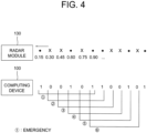
Fig. 4 is a drawing schematically illustrating a process of acquiring first circumstance information from first V2V receiving information acquired by using first receiving signals inputted at a first timing in a first time slot, to be used for performing the method for the V2V communication by using the radar module used for detecting objects nearby in accordance with one example embodiment of the present disclosure. - Detailed explanation on the present disclosure to be made below refer to attached drawings and diagrams illustrated as specific embodiment examples under which the present disclosure may be implemented to make clear of purposes, technical solutions, and advantages of the present disclosure. These embodiments are described in sufficient detail to enable those skilled in the art to practice the disclosure.
- Besides, in the detailed description and claims of the present disclosure, a term "include" and its variations are not intended to exclude other technical features, additions, components or steps. Other objects, benefits, and features of the present disclosure will be revealed to one skilled in the art, partially from the specification and partially from the implementation of the present disclosure. The following examples and drawings will be provided as examples but they are not intended to limit the present disclosure.
- Moreover, the present disclosure covers all possible combinations of example embodiments indicated in this specification. It is to be understood that the various embodiments of the present disclosure, although different, are not necessarily mutually exclusive. For example, a particular feature, structure, or characteristic described herein in connection with one embodiment may be implemented within other embodiments without departing from the scope of the present disclosure as defined by the appended claims. In addition, it is to be understood that the position or arrangement of individual elements within each disclosed embodiment may be modified without departing from the scope of the present disclosure as defined by the appended claims. The following detailed description is, therefore, not to be taken in a limiting sense, and the scope of the present disclosure is defined only by the appended claims, appropriately interpreted, along with the full range of equivalents to which the claims are entitled. In the drawings, like numerals refer to the same or similar functionality throughout the several views.
- To allow those skilled in the art to the present disclosure to be carried out easily, the example embodiments of the present disclosure by referring to attached drawings will be explained in detail as shown below.
-
Fig. 1 is a drawing schematically illustrating a configuration of a computing device performing a method for a V2V communication by using a radar module used for detecting objects nearby in accordance with one example embodiment of the present disclosure. - By referring to
Fig. 1 , thecomputing device 100 may include at least oneradar module 130. Processes of input/output and computation of theradar module 130 may be respectively performed by at least onecommunication part 110 and at least oneprocessor 120. However, detailed communication schematics between thecommunication part 110 and theprocessor 120 are omitted inFig. 1 . Herein, amemory 115 may have stored various instructions to be described later, and theprocessor 120 may execute the instructions stored in thememory 115 and may perform processes of the present disclosure by executing the instructions to be disclosed later. Such description of thecomputing device 100 does not exclude an integrated device including any combination of a processor, a memory, a medium, or any other computing components. -
Such computing device 100 may have been installed on a subject vehicle, and the subject vehicle may further include an autonomous driving module, which interworks with thecomputing device 100, to be used for performing an autonomous driving of the subject vehicle. The autonomous driving module may perform the autonomous driving by referring to RVA information, first circumstance information and second circumstance information to be explained later. - So far the configuration of the
computing device 100 to be used for performing the method for the V2V communication by using theradar module 130 used for detecting objects nearby in accordance with one example embodiment of the present disclosure has been explained. Below, the method for the V2V communication itself will be explained, first by referring toFig. 2 . -
Fig. 2 is a flow chart schematically illustrating the method for the V2V communication by using the radar module used for detecting objects nearby in accordance with one example embodiment of the present disclosure. - By referring to
Fig. 2 , at a step of S01-1, thecomputing device 100, if a 1-st trigger that a 1-st timing corresponding to a current time is included in a 1-st time slot is detected, may perform a process of instructing theradar module 130 to transmit one or more 1-st transmitting signals, to be used for acquiring the RVA information on 1-st surrounding objects including 1-st surrounding vehicles near the subject vehicle by referring to at least one 1-st schedule. Also, in parallel with the step of S01-1, at a step of S01-2, thecomputing device 100 may perform a process of generating the RVA information by using one or more (1-1)-st receiving signals, corresponding to the 1-st transmitting signals, acquired through theradar module 130. During the same time slot, i.e., the 1-st time slot, in parallel with said steps of S01-1 and S01-2, a process may be further performed as the case may be. That is, at a step of S01-3, thecomputing device 100, if one or more (1-2)-nd receiving signals are acquired through theradar module 130 from at least part of the 1-st surrounding objects, may perform a process of generating 1-st V2V receiving information by referring to the (1-2)-nd receiving signals. - Thereafter, at a step of S02-1, if a 2-nd trigger that a 2-nd timing corresponding to a later time from the 1-st timing is included in a 2-nd time slot is detected, the
computing device 100 may perform a process of instructing theradar module 130 to transmit one or more 2-nd transmitting signals by referring to at least one 2-nd schedule, corresponding to V2V transmitting information on the subject vehicle. Also, similar to processes performed during the 1-st time slot, during the 2-nd time slot, in parallel with the step of S02-1, a process can be further performed as the case may be. That is, thecomputing device 100, if one or more 2-nd receiving signals are acquired through theradar module 130 from at least part of 2-nd surrounding vehicles near the subject vehicle at the 2-nd timing, may perform a process of generating 2-nd V2V receiving information on at least part of the 2-nd surrounding vehicles by referring to the 2-nd receiving signals. - So far the V2V communication method of the present disclosure has been explained briefly, below it will be explained more specifically. By performing the method proposed by the present disclosure, two processes, i.e., a process of acquiring the RVA information and a process of performing the V2V communication, can be performed. In this regard, those two processes will be explained separately. Herein, the process of acquiring the RVA information may be performed during the 1-st time slot, and the process of the V2V communication may be mainly performed during the 2-nd time slot, but also can be subsidiarily performed during the 1-st time slot. The reason why a time range should be divided into such time slots will be explained later too. First, the process of acquiring the RVA information will be explained.
- Herein, the RVA information may be a kind of information on a range, a velocity and an angle of an object, and may be a basic information which the
radar module 130, using Frequency Modulated Continuous Wave(FMCW) signals, can acquire conventionally. Thus, the process of acquiring the RVA information may be similar to that of a prior art. In order to acquire the RVA information, thecomputing device 100 may instruct theradar module 130 to instruct theradar module 130 to transmit the 1-st transmitting signals to the 1-st surrounding vehicles, i.e., vehicles located closer than a first threshold from the subject vehicle at the first timing. Herein, the 1-st transmitting signals may have been built as chirp signals. And, the 1-st schedule may represent a schedule of transmitting the 1-st transmitting signals in a prescribed frequency during the 1-st time slot. As an example, the 1-st schedule may represent a schedule of transmitting 128 or 256 1-st transmitting signals during the 1-st time slot. - If the 1-st transmitting signals are transmitted to at least part of the 1-st surrounding vehicles, the (1-1)-st receiving signals, as reflected signals of the 1-st transmitting signals, may be acquired through the
radar module 130. After the (1-1)-st receiving signals are acquired, thecomputing device 100 may generate each of one or more Intermediate Frequency(IF) signals between each of the 1-st transmitting signals and each of the (1-1)-st receiving signals, and then apply a Fourier Transform to the IF signals, to thereby generate the RVA information. As said before, such process is similar to that of a conventional FMCW radar scheme, thus above explanation will be sufficient for a person in the art. - Below, the process of the V2V communication will be explained. First, the process can be divided into a transmitting process and a receiving process. Herein, the transmitting process may be performed during the 2-nd time slot, and the receiving process may be performed during both of the 1-st time slot and the 2-nd time slot. Regarding the transmitting process, if the 2-nd trigger that the 2-nd timing corresponding to a later time from the 1-st timing is included in the the 2-nd time slot is detected, the
computing device 100 may perform a process of instructing theradar module 130 to transmit the 2-nd transmitting signals by referring to the 2-nd schedule, corresponding to the V2V transmitting information on the subject vehicle. - Herein, the 2-nd schedule may have been acquired by referring to a specific reference data permutation corresponding to a specific circumstance of the subject vehicle and a reference length included in a communication rule of the V2V communication, which is shared among vehicles capable of the V2V communication. Each of reference data permutations, including the specific reference data permutation, may be each of binary permutations which has been prescribed for each of circumstances of an example vehicle. For example, if the example vehicle is in an emergency situation, its corresponding reference data permutation may be 1, 0, 0, 1, 0, 1. Otherwise, if an accident has occurred near the example vehicle, its corresponding reference data permutation may be 1, 0, 0, 0, 1, 1. Herein, a starting signal and an ending signal of each of the reference data permutations may have been set as 1, to tag those as guide bits which makes a detection of the reference data permutations among flows of arbitrary binary signals easier. In the explanations above, it was illustrated that two guide bits are set in each of the reference data permutations, i.e., one in a foremost bit and the other one in a backmost bit, for convenience, but more bits, e.g., two in the front and other two in the back, or three in the front and other three in the back, can be set as the guide bits.
- Under an assumption that the reference data permutations are set as shown above, the
computing device 100 may, by referring to the 2-nd schedule, transmit the 2-nd transmitting signals in a frequency corresponding to one of the reference data permutations, e.g., the specific reference data permutation. In order to take a look at an example of transmitting the 2-nd transmitting signals,Fig. 3 will be referred to. -
Fig. 3 is a drawing schematically illustrating a process of transmitting second transmitting signals to be used for performing the method for the V2V communication by using the radar module used for detecting objects nearby in accordance with one example embodiment of the present disclosure. - By referring to
Fig. 3 , it can be seen that the subject vehicle is in the emergency situation, and the reference length is 0.9sec. In this case, thecomputing device 100 may transmit the 2-nd transmitting signals in a 0.15sec timing, a 0.6sec timing and a 0.9sec timing. In this way, at least part of the 2-nd surrounding vehicles may receive the 2-nd transmitting signals, to thereby acquire information on the emergency situation of the subject vehicle. If the 2-nd time slot corresponds to 4.5 seconds, the 2-nd transmitting signals can be transmitted for 5 cycles by referring to the 2-nd schedule. - Hereinafter, the receiving process of the V2V communication method will be explained.
- When other vehicles transmit signals to the subject vehicle, they just transmit those in their own schedules. Thus, different from the transmitting process performed only during the 2-nd time slot, the receiving process can be performed during both the 1-st time slot and the 2-nd time slot. During the 1-st time slot, in order to perform the receiving process properly, an additional process is necessary. Except that, it is same during the 1-st time slot and the 2-nd time slot. First, the receiving process performed during the 1-st time slot will be explained.
- During the 1-st time slot, the (1-1)-st receiving signals, which are the reflected signals of the 1-st transmitting signals, are acquired along with the (1-2)-nd receiving signals, thus a process of distinguishing those two kinds of receiving signals is necessary.
- In this regard, if a time gap between receiving timings of its two inputted receiving signals is larger than or same as a second threshold, the
computing device 100 may generate two IF signals between one of the 1-st transmitting signals and said two inputted receiving signals. Then, thecomputing device 100 may determine whether each of center frequencies of each of the IF signals is included in a 1-st frequency range or a 2-nd frequency range, to thereby determine whether each of said inputted receiving signals is included in the (1-1)-st receiving signals or the (1-2)-nd receiving signals. Herein, since the (1-1)-st receiving signals are reflected signals of the 1-st transmitting signals, thus a center frequency of its corresponding IF signal between them may be relatively smaller. More specifically, the (1-1)-st receiving signals and the 1-st transmitting signals will be similar to each other due to their relationship, i.e., original ones and reflected ones, thus the center frequencies of the IF signals, which represents differences between those, may be relatively smaller. However, on the other hand, since the (1-2)-nd receiving signals are not related to the 1-st transmitting signals, a center frequency of its corresponding IF signal between them may be relatively larger. Therefore, on condition that the 1-st frequency range has been set as smaller than the 2-nd frequency range, one of the inputted receiving signals whose corresponding center frequency is included in the 1-st frequency range can be determined as being included in the (1-1)-st receiving signals, and another one of the inputted receiving signals whose corresponding center frequency is included in the 2-nd frequency range can be determined as being included in the 2-nd receiving signals. - Different from this case, if the time gap is smaller than the second threshold, the
computing device 100 may not able to distinguish those two by using something similar to said IF signals. Thus, the computing device may just instruct the radar module to continuously acquire receiving signals until a meta data permutation to be explained later is fully generated. As an example, if an interference between two inputted receiving signals is detected so that a proper acquisition of information is failed, a specific receiving signal, which is acquired at a timing later than a time corresponding to the reference length from a timing corresponding to the interference, may be determined as one of the (1-2)-nd receiving signals, to thereby become a component of said meta data permutation. - However, since the process of acquiring the RVA information is more important process to be performed during the 1-st time slot, a frequency interference prevention filter may be used during the 1-st time slot even though it may disturb the process of the V2V communication.
- So far the process of preventing an interference between inputted receiving signals has been explained. Below, a process of generating the 1-st V2V receiving information by using the (1-2)-nd receiving signals will be explained. If the (1-2)-nd receiving signals are acquired as shown above, the
computing device 100 may find at least one starting signal and at least one ending signal among the (1-2)-nd receiving signals by referring to the reference length, and then generate the meta data permutation including at least part of the (1-2)-nd receiving signals between the starting signal and the ending signal. Thereafter, thecomputing device 100 may compare the meta data permutations and said reference data permutations and may find a specific reference data permutation whose similarity score is larger than a third threshold, to thereby acquire the 1-st V2V receiving information corresponding to the specific reference data permutation, and then to thereby acquire the 1-st circumstance information by using the 1-st V2V receiving information. In order to take a look at an example of said process,Fig. 4 will be referred to. -
Fig. 4 is a drawing schematically illustrating a process of acquiring the 1-st circumstance information from the 1-st V2V receiving information acquired by using first receiving signals inputted at the 1-st timing in the 1-st time slot, to be used for performing the method for the V2V communication by using the radar module used for detecting objects nearby in accordance with one example embodiment of the present disclosure. - By referring to
Fig. 4 , an example of the (1-2)-nd receiving signals, which are noted as 1, 0, 0, 1, 0, 1, 1, 0, 0, 1, 0, 1, 1, 0, 0, 1, 0, 1, acquired by thecomputing device 100 may be seen. If it is known that the reference length is 6, thecomputing device 100 may find two 1s whose gap is 6, and may determine those two 1s as the starting signal and the ending signal. And, thecomputing device 100 may determine themeta data permutation computing device 100 may acquire the 1-st circumstance information representing that a danger is present around a vehicle which transmitted the (1-2)-nd receiving signals. - Also in timings included in the 2-nd time slot, the
computing device 100 may be able to generate 2-nd V2V receiving information on at least part of the 2-nd surrounding vehicles located closer than said first threshold from the subject vehicle by using said one or more 2-nd receiving signals, and then generate the 2-nd circumstance information by using the 2-nd V2V receiving information. Such process will be similar to that illustrated inFig. 4 , but said process of distinguishing two inputted receiving signals will not be performed, and said frequency interference prevention filter may not be used. Said process of distinguishing is not necessary because no reflected signals are acquired during the 2-nd time slot, and the frequency interference prevention filter is not necessary because it is a component for just acquiring the RVA information. - After the 1-st circumstance information and the 2-nd circumstance information are acquired, the
computing device 100 may support the autonomous driving of the subject vehicle by using those. That is, during the 1-st time slot, thecomputing device 100 may generate the 1-st circumstance information on at least part of the 1-st surrounding vehicles by referring to the 1-st V2V receiving information, and then support the autonomous driving of the subject vehicle by using the 1-st circumstance information. Also, during the 2-nd time slot, thecomputing device 100 may generate the 2-nd circumstance information on at least part of the 2-nd surrounding vehicles by referring to the 2-nd V2V receiving information, and then support the autonomous driving of the subject vehicle by using the 2-nd circumstance information. - Herein, among the 2-nd circumstance information, (2-1)-st circumstance information on one or more specific vehicles included in both of the 1-st surrounding vehicles and the 2-nd surrounding vehicles may be acquired by updating at least part of the 1-st circumstance information on the specific vehicles, using at least part of the 2-nd V2V receiving information. It is possible because the 1-st time slot and the 2-nd time slot are located in serial and sizes of the two are not so large, thus there may be many duplicated ones included in both of the 1-st surrounding vehicles and the 2-nd surrounding vehicles. And, among the 2-nd circumstance information, (2-2)-nd circumstance information on other vehicles of the 2-nd surrounding vehicles other than the specific vehicles may be acquired from scratch by using another part of the 2-nd V2V receiving information, not like the (2-1)-st circumstance information which is not acquired from scratch but acquired by updating the 1-st circumstance information. Said other vehicles are relatively new ones comparing to the specific vehicles, thus such process will be very natural.
- The 1-st time slot and the 2-nd time slot may be set in serial, alternatively. That is, first 4.5 sec range may be the 1-st time slot, and its next 4.5 sec range after that may be the 2-nd time slot. Then, again 4.5 sec range after that may be the 1-st time slot, and so on. During each of the time slots, each of said processes for each of the time slots may be performed, and the
computing device 100 may be able to acquire the RVA information and the circumstance information continuously and transmit its V2V transmitting information to other vehicles, to thereby acquire a safer autonomous driving. - It is a positive effect of the present disclosure to provide a method for the V2V communication through the radar module using the FMCW signals without additional cost. And, it is still another positive effect of the present disclosure to allow the radar module to perform the V2V communication while performing its original functions, by transmitting different signals according to time slots. Finally, it is still yet another positive effect of the present disclosure to establish the V2V communication by allowing each of vehicles to share its own circumstance information with other vehicles, using prescribed data permutations.
- The embodiments of the present disclosure as explained above can be implemented in a form of executable program command through a variety of computer means recordable to computer readable media. The computer readable media may include solely or in combination, program commands, data files, and data structures. The program commands recorded to the media may be components specially designed for the present disclosure or may be usable to a skilled human in a field of computer software. Computer readable media include magnetic media such as hard disk, floppy disk, and magnetic tape, optical media such as CD-ROM and DVD, magneto-optical media such as floptical disk and hardware devices such as ROM, RAM, and flash memory specially designed to store and carry out program commands. Program commands include not only a machine language code made by a compiler but also a high level language code that can be executed by a computer using an interpreter, etc. The hardware device can work as more than a software module to perform the process in accordance with the present disclosure and they can do the same in the opposite case.
- As seen above, the present disclosure has been explained by specific matters such as detailed components, limited embodiments, and drawings. They have been provided only to help more general understanding of the present disclosure. It, however, will be understood by those skilled in the art that various changes and modification may be made from the description without departing from the scope of the disclosure as defined in the following claims.
Claims (13)
- A method for a V2V communication by using a radar module (130) used for detecting objects nearby, comprising steps of:(a1) detecting a 1-st trigger indicating that a 1-st timing corresponding to a current time is included in a 1-st time slot,(a2) upon said detecting a 1-st trigger, a computing device (100) performing:(i) a process of instructing the radar module (130) to transmit one or more 1-st transmitting signals, to be used for acquiring information on a range, a velocity and an angle of an object (RVA information) on at least part of one or more head directions, one or more relative locations and one or more relative velocities of at least part of one or more 1-st surrounding objects including one or more 1-st surrounding vehicles located closer than a first threshold from a subject vehicle interworking with the computing device at the 1-st timing, by referring to at least one 1-st transmitting schedule and(ii) a process of generating the RVA information by using one or more (1-1)-st receiving signals, corresponding to the 1-st transmitting signals, that are acquired through the radar module in the 1-st time slot; and(b1) detecting a 2-nd trigger indicating that a 2-nd timing corresponding to a later time from the 1-st timing is included in a 2-nd time slot,(b2) upon said detecting the 2-nd trigger, the computing device performing a process of instructing the radar module to transmit one or more 2-nd transmitting signals by referring to at least one 2-nd transmitting schedule, corresponding to V2V transmitting information on the subject vehicle, wherein, at the steps of (a1) and (a2) the computing device (100), if one or more (1-2)-nd receiving signals are acquired through the radar module (130) from at least part of the 1-st surrounding objects in the 1-st time slot, further performs a process of generating 1-st V2V receiving information by referring to the (1-2)-nd receiving signals in parallel with the other processes performed during the steps of (a1) and (a2), and wherein, at the steps of (b1) and (b2), the computing device, if one or more 2-nd receiving signals are acquired through the radar module from at least part of 2-nd surrounding vehicles which are located closer than the first threshold from the subject vehicle at the 2-nd timing, performs a process of generating 2-nd V2V receiving information on at least part of the 2-nd surrounding vehicles by referring to the 2-nd receiving signals in parallel with the other process performed during the steps of (b1) and (b2).
- The method of Claim 1, wherein, at the steps of (a1) and (a2), the computing device (100) (i) detects at least one starting signal and at least one ending signal among the (1-2)-nd receiving signals by referring to a reference length included in a communication rule of the V2V communication, (ii) generates at least one meta data permutation including at least part of the (1-2)-nd receiving signals between the starting signal and the ending signal, and then (iii) generates the 1-st V2V receiving information by referring to the meta data permutation.
- The method of Claim 2, wherein, at the steps of (a1) and (a2), the computing device (100), if a time gap between receiving timings of its (1-1)-st and its (1-2)-nd inputted receiving signals is smaller than a second threshold and thus if the inputted receiving signals are not determined as being included in the (1-1)-st receiving signals or as being included in the (1-2)-nd receiving signals, instructs the radar module (130) to continuously receive receiving signals until the meta data permutation for the (1-2)-nd receiving signal is generated.
- The method of Claim 2, wherein, at the steps of (a1) and (a2) the computing device (100) compares the meta data permutation and each of one or more reference data permutations corresponding to each of driving circumstances, to find a specific reference data permutation whose similarity score with the meta data permutation is larger than a third threshold, to thereby generate the 1-st V2V receiving information for a specific driving circumstance corresponding to the specific reference data permutation whose similarity score with the meta data permutation is larger than the third threshold.
- The method of Claim 1, wherein, at the steps of (a1) and (a2), the computing device (100) generates 1-st circumstance information on at least part of the 1-st surrounding vehicles by referring to the 1-st V2V receiving information, to thereby support an autonomous driving of the subject vehicle by referring to the 1-st circumstance information, andwherein, at the steps of (b1) and (b2), the computing device generates 2-nd circumstance information on at least part of the 2-nd surrounding vehicles by referring to the 2-nd V2V receiving information, to thereby support the autonomous driving of the subject vehicle by referring to the 2-nd circumstance information, wherein the 2-nd circumstance information comprises (2-1)-st circumstance information and (2-2)-nd circumstance information,wherein the (2-1)-st circumstance information among the 2-nd circumstance information is acquired by updating at least part of the 1-st circumstance information on one or more specific vehicles included in both of the 1-st surrounding vehicles and the 2-nd surrounding vehicles, using at least part of the 2-nd V2V receiving information thereon, andwherein the (2-2)-nd circumstance information on another vehicles among the 2-nd surrounding vehicles other than the specific vehicles is acquired by another part of the 2-nd V2V receiving information.
- The method of Claim 1, wherein, at the steps of (b1) and (b2), the computing device (100) transmits the 2-nd transmitting signals with its transmitting timings determined by referring to the 2-nd transmitting schedule to thereby deliver the V2V transmitting information to at least part of the 2-nd surrounding vehicles, wherein the 2-nd transmitting schedule has been acquired by referring to a specific reference data permutation corresponding to the V2V transmitting information among each of one or more reference data permutations for each of driving circumstances and a reference length included in a communication rule of the V2V communication.
- The method of Claim 1, wherein, at the steps of (a1) and (a2), the computing device (100), if a time gap between receiving timings of its (1-1)-st and its (1-2)-nd inputted receiving signals is larger than or same as a second threshold, (i) generates Intermediate Frequency(IF) signals between one of the 1-st transmitting signals and said inputted receiving signals, (ii) determines whether each of center frequencies of each of the IF signals is included in a 1-st frequency range or is included in a 2-nd frequency range, to thereby determine whether each of said inputted receiving signals is included in the (1-1)-st receiving signals or the (1-2)-nd receiving signals.
- The method of Claim 1, wherein the computing device (100) uses a frequency interference prevention filter to acquire the (1-1)-st receiving signals and the (1-2)-nd receiving signals at a timing included in the 1-st time slot, and
wherein the computing device does not use the frequency interference prevention filter to acquire the 2-nd receiving signals at a timing included in the 2-nd time slot. - The method of Claim 1, wherein, at the steps of (a1) and (a2), as the computing device (100) instructs the radar module (130) to transmit the 1-st transmitting signals built as chirp signals, the computing device (i) acquires the (1-1)-st receiving signals, which are reflected signals of the 1-st transmitting signals, through the radar module, (ii) generates each of one or more Intermediate Frequency(IF) signals between each of the 1-st transmitting signals and each of the (1-1)-st receiving signals, and (iii) generates the RVA information by applying a Fourier transform to the IF signals.
- A computing device (100) for a V2V communication by using a radar module (130) used for detecting objects nearby, comprising:at least one memory (115) that stores instructions; andat least one processor (120) configured to execute the instructions to perform processes of:(Ia) detecting a 1-st trigger that indicates that a 1-st timing corresponding to a current time is included in a 1-st time slot,(Ib) upon said detecting:(i) instructing the radar module (130) to transmit one or more 1-st transmitting signals, to be used for acquiring information on a range, a velocity and an angle of an object (RVA information) on at least part of one or more head directions, one or more relative locations and one or more relative velocities of at least part of one or more 1-st surrounding objects including one or more 1-st surrounding vehicles located closer than a first threshold from a subject vehicle interworking with the computing device at the 1-st timing, by referring to at least one 1-st transmitting schedule and(ii) generating the RVA information by using one or more (1-1)-st receiving signals, corresponding to the 1-st transmitting signals, that are acquired through the radar module in the 1-st time slot; and(IIa) detecting a 2-nd trigger indicating that a 2-nd timing corresponding to a later time from the 1-st timing is included in a 2-nd time slot,(IIb) upon detecting the 2-nd trigger instructing the radar module to transmit one or more 2-nd transmitting signals by referring to at least one 2-nd transmitting schedule, corresponding to V2V transmitting information on the subject vehicle, wherein, at the processes of (Ia) and (Ib), the processor (120) , if one or more (1-2)-nd receiving signals are acquired through the radar module (130) from at least part of the 1-st surrounding objects in the 1-st time slot, further performs a process of generating 1-st V2V receiving information by referring to the (1-2)-nd receiving signals in parallel with the processes of (Ia) and (Ib), andwherein, at the processes of (IIa) and (IIb), the processor, if one or more 2-nd receiving signals are acquired through the radar module from at least part of 2-nd surrounding vehicles which are located closer than the first threshold from the subject vehicle at the 2-nd timing, performs a process of generating 2-nd V2V receiving information on at least part of the 2-nd surrounding vehicles by referring to the 2-nd receiving signals in parallel with the processes of (IIa) and (IIb).
- The computing device (100) of Claim 10, wherein, at the processes of (Ia) and (Ib), the processor (120) (i) detects at least one starting signal and at least one ending signal among the (1-2)-nd receiving signals by referring to a reference length included in a communication rule of the V2V communication, (ii) generates at least one meta data permutation including at least part of the (1-2)-nd receiving signals between the starting signal and the ending signal, and then (iii) generates the 1-st V2V receiving information by referring to the meta data permutation.
- The computing device (100) of Claim 10, wherein, at the processes of (Ia) and (Ib), the processor (120) generates 1-st circumstance information on at least part of the 1-st surrounding vehicles by referring to the 1-st V2V receiving information, to thereby support an autonomous driving of the subject vehicle by referring to the 1-st circumstance information, andwherein at the processes of (IIa) and (IIb), the processor generates 2-nd circumstance information on at least part of the 2-nd surrounding vehicles by referring to the 2-nd V2V receiving information, to thereby support the autonomous driving of the subject vehicle by referring to the 2-nd circumstance information, wherein the 2-nd circumstance information comprises (2-1)-st circumstance information and (2-2)-nd circumstance information,wherein the (2-1)-st circumstance information among the 2-nd circumstance information is acquired by updating at least part of the 1-st circumstance information on one or more specific vehicles included in both of the 1-st surrounding vehicles and the 2-nd surrounding vehicles, using at least part of the 2-nd V2V receiving information thereon, andwherein the (2-2)-nd circumstance information on another vehicles among the 2-nd surrounding vehicles other than the specific vehicles is acquired by another part of the 2-nd V2V receiving information.
- The computing device (100) of Claim 10, wherein, at the processes of (Ia) and (Ib), as the processor (120) instructs the radar module (130) to transmit the 1-st transmitting signals built as chirp signals, the processor (i) acquires the (1-1)-st receiving signals, which are reflected signals of the 1-st transmitting signals, through the radar module, (ii) generates each of one or more Intermediate Frequency(IF) signals between each of the 1-st transmitting signals and each of the (1-1)-st receiving signals, and (iii) generates the RVA information by applying a Fourier transform to the IF signals.
Applications Claiming Priority (2)
| Application Number | Priority Date | Filing Date | Title |
|---|---|---|---|
| US201962799193P | 2019-01-31 | 2019-01-31 | |
| US16/731,953 US10779139B2 (en) | 2019-01-31 | 2019-12-31 | Method and device for inter-vehicle communication via radar system |
Publications (3)
| Publication Number | Publication Date |
|---|---|
| EP3690477A1 EP3690477A1 (en) | 2020-08-05 |
| EP3690477B1 true EP3690477B1 (en) | 2023-09-13 |
| EP3690477C0 EP3690477C0 (en) | 2023-09-13 |
Family
ID=69187628
Family Applications (1)
| Application Number | Title | Priority Date | Filing Date |
|---|---|---|---|
| EP20153076.3A Active EP3690477B1 (en) | 2019-01-31 | 2020-01-22 | Method and device for inter-vehicle communication via radar system |
Country Status (5)
| Country | Link |
|---|---|
| US (1) | US10779139B2 (en) |
| EP (1) | EP3690477B1 (en) |
| JP (1) | JP7104991B2 (en) |
| KR (1) | KR102306343B1 (en) |
| CN (1) | CN111505616B (en) |
Families Citing this family (2)
| Publication number | Priority date | Publication date | Assignee | Title |
|---|---|---|---|---|
| JP7331085B2 (en) * | 2018-08-14 | 2023-08-22 | シグニファイ ホールディング ビー ヴィ | MICROWAVE SENSOR DEVICE, SENSING METHOD, AND LIGHTING SYSTEM USING SENSOR DEVICE |
| CN112099037B (en) * | 2020-09-17 | 2023-11-10 | 上海波汇科技有限公司 | Target detection method and device based on FMCW laser radar Gao Dian cloud acquisition |
Family Cites Families (26)
| Publication number | Priority date | Publication date | Assignee | Title |
|---|---|---|---|---|
| US7629899B2 (en) * | 1997-10-22 | 2009-12-08 | Intelligent Technologies International, Inc. | Vehicular communication arrangement and method |
| US7418346B2 (en) * | 1997-10-22 | 2008-08-26 | Intelligent Technologies International, Inc. | Collision avoidance methods and systems |
| US8255144B2 (en) * | 1997-10-22 | 2012-08-28 | Intelligent Technologies International, Inc. | Intra-vehicle information conveyance system and method |
| US8965677B2 (en) * | 1998-10-22 | 2015-02-24 | Intelligent Technologies International, Inc. | Intra-vehicle information conveyance system and method |
| JP2003058995A (en) | 2001-08-15 | 2003-02-28 | Fujitsu Ltd | Traffic support programs and devices |
| DE102005048209A1 (en) * | 2005-09-29 | 2007-04-05 | Valeo Schalter Und Sensoren Gmbh | Frequency modulated continuous wave radar method for motor vehicle, involves determining portion of surrounding of vehicle in time segment, and determining distances for object in another portion of surrounding in another time segment |
| JP2007132768A (en) * | 2005-11-10 | 2007-05-31 | Hitachi Ltd | In-vehicle radar device with communication function |
| JP2007155551A (en) * | 2005-12-06 | 2007-06-21 | Toyota Motor Corp | In-vehicle radar system |
| JP2007189436A (en) | 2006-01-12 | 2007-07-26 | Toyota Motor Corp | Inter-vehicle communication device |
| KR100813909B1 (en) * | 2006-05-15 | 2008-03-18 | 한국전기연구원 | Car radar dual mode system with wireless communication function |
| JP5126529B2 (en) | 2008-09-19 | 2013-01-23 | トヨタ自動車株式会社 | Radar apparatus and target velocity traveling direction estimation method |
| DE102009054776A1 (en) * | 2009-01-23 | 2010-08-12 | Adc Automotive Distance Control Systems Gmbh | Communication system for use in driver assistance system of e.g. vehicle, has radar module for executing communication function, which executes transmission of communication signal via radar signal to adjacent vehicle |
| US8229663B2 (en) * | 2009-02-03 | 2012-07-24 | GM Global Technology Operations LLC | Combined vehicle-to-vehicle communication and object detection sensing |
| US8730088B2 (en) * | 2010-08-09 | 2014-05-20 | Raytheon Bbn Technologies Corp. | Radar coherent processing interval scheduling via ad hoc network |
| US20130278441A1 (en) * | 2012-04-24 | 2013-10-24 | Zetta Research and Development, LLC - ForC Series | Vehicle proxying |
| US9253753B2 (en) * | 2012-04-24 | 2016-02-02 | Zetta Research And Development Llc-Forc Series | Vehicle-to-vehicle safety transceiver using time slots |
| KR102075110B1 (en) * | 2012-09-07 | 2020-02-10 | 주식회사 만도 | Apparatus of identificating vehicle based vehicle-to-vehicle communication, and method of thereof |
| US9340154B2 (en) * | 2014-06-11 | 2016-05-17 | Socpra Sciences Et Génie S.E.C. | Collision avoidance in vehicular networks |
| US20160223643A1 (en) * | 2015-01-28 | 2016-08-04 | Wenhua Li | Deep Fusion of Polystatic MIMO Radars with The Internet of Vehicles for Interference-free Environmental Perception |
| KR101694476B1 (en) * | 2015-07-21 | 2017-01-10 | 재단법인대구경북과학기술원 | Device and method for tranceiver |
| CN107561532A (en) * | 2016-06-30 | 2018-01-09 | 北京行易道科技有限公司 | imaging radar, vehicle and imaging method |
| JP6468260B2 (en) * | 2016-08-04 | 2019-02-13 | トヨタ自動車株式会社 | Wireless communication apparatus and wireless communication method |
| EP3339898A1 (en) * | 2016-12-20 | 2018-06-27 | Nxp B.V. | Sensor data network |
| US10094933B1 (en) * | 2017-03-23 | 2018-10-09 | Delphi Technologies, Inc. | Automated vehicle GPS accuracy improvement using V2V communications |
| US10082562B1 (en) * | 2018-04-27 | 2018-09-25 | Lyft, Inc. | Simultaneous object detection and data transfer with a vehicle radar |
| CN109212520B (en) * | 2018-09-29 | 2021-04-27 | 河北德冠隆电子科技有限公司 | Road condition sensing abnormal event detection alarm system and method for omnibearing detection radar |
-
2019
- 2019-12-31 US US16/731,953 patent/US10779139B2/en active Active
-
2020
- 2020-01-13 KR KR1020200004521A patent/KR102306343B1/en active Active
- 2020-01-21 CN CN202010071500.XA patent/CN111505616B/en active Active
- 2020-01-22 JP JP2020007950A patent/JP7104991B2/en active Active
- 2020-01-22 EP EP20153076.3A patent/EP3690477B1/en active Active
Also Published As
| Publication number | Publication date |
|---|---|
| CN111505616A (en) | 2020-08-07 |
| KR20200095366A (en) | 2020-08-10 |
| KR102306343B1 (en) | 2021-09-30 |
| JP7104991B2 (en) | 2022-07-22 |
| JP2020127193A (en) | 2020-08-20 |
| US20200252770A1 (en) | 2020-08-06 |
| EP3690477A1 (en) | 2020-08-05 |
| CN111505616B (en) | 2023-03-28 |
| US10779139B2 (en) | 2020-09-15 |
| EP3690477C0 (en) | 2023-09-13 |
Similar Documents
| Publication | Publication Date | Title |
|---|---|---|
| KR102384973B1 (en) | vehicle radar system | |
| US9972211B2 (en) | Communication device and communication method | |
| US20120169523A1 (en) | Method and radar apparatus for detecting target object | |
| EP3690477B1 (en) | Method and device for inter-vehicle communication via radar system | |
| JP7044163B2 (en) | Remote parking assistance message flow system and method | |
| EP2637149B1 (en) | Onboard device and control method | |
| EP3252733B1 (en) | Communication device and communication method | |
| US9663126B2 (en) | Embedded system for generating a rail vehicle location signal | |
| JP6946570B2 (en) | Car sensor fusion performed in response to a signal | |
| JP2009276939A (en) | Radio frequency id tag system | |
| US10002532B2 (en) | Communication device and method | |
| US10908253B2 (en) | Interference mitigation in automotive radar systems by artificial doppler modulation | |
| EP3451015A1 (en) | Method and apparatus for detecting object using radar of vehicle | |
| US8483890B2 (en) | Identification of ship state tonal parameters for use in relative GPS shipboard landing systems | |
| CN105184878B (en) | Exclude the method for commerce of monkey chatter, roadside unit and multilane system in the same direction | |
| CN113359121B (en) | Signal processing method and device | |
| KR101682090B1 (en) | Apparatus and method for controlling output of jamming signal using unknown signal | |
| EA201990830A1 (en) | METHOD FOR PREVENTING COLLISIONS BASED ON RELATIVE RADIO NAVIGATION | |
| EP4198561A1 (en) | Frequency modulated continuous wave (fmcw) waveform generator/decoder | |
| JP7271638B1 (en) | Communication device and communication method | |
| US20220250617A1 (en) | Threat mitigation for vehicles | |
| KR20150133472A (en) | System and method for sharing information using radars of vehicle | |
| KR101694476B1 (en) | Device and method for tranceiver | |
| CN116224242A (en) | Multi-Channel Joint Interference Mitigation | |
| KR20240140364A (en) | Vehicle matching system and method of thereof |
Legal Events
| Date | Code | Title | Description |
|---|---|---|---|
| PUAI | Public reference made under article 153(3) epc to a published international application that has entered the european phase |
Free format text: ORIGINAL CODE: 0009012 |
|
| STAA | Information on the status of an ep patent application or granted ep patent |
Free format text: STATUS: REQUEST FOR EXAMINATION WAS MADE |
|
| 17P | Request for examination filed |
Effective date: 20200222 |
|
| AK | Designated contracting states |
Kind code of ref document: A1 Designated state(s): AL AT BE BG CH CY CZ DE DK EE ES FI FR GB GR HR HU IE IS IT LI LT LU LV MC MK MT NL NO PL PT RO RS SE SI SK SM TR |
|
| AX | Request for extension of the european patent |
Extension state: BA ME |
|
| RBV | Designated contracting states (corrected) |
Designated state(s): AL AT BE BG CH CY CZ DE DK EE ES FI FR GB GR HR HU IE IS IT LI LT LU LV MC MK MT NL NO PL PT RO RS SE SI SK SM TR |
|
| STAA | Information on the status of an ep patent application or granted ep patent |
Free format text: STATUS: EXAMINATION IS IN PROGRESS |
|
| 17Q | First examination report despatched |
Effective date: 20220518 |
|
| GRAP | Despatch of communication of intention to grant a patent |
Free format text: ORIGINAL CODE: EPIDOSNIGR1 |
|
| STAA | Information on the status of an ep patent application or granted ep patent |
Free format text: STATUS: GRANT OF PATENT IS INTENDED |
|
| INTG | Intention to grant announced |
Effective date: 20230328 |
|
| GRAS | Grant fee paid |
Free format text: ORIGINAL CODE: EPIDOSNIGR3 |
|
| GRAA | (expected) grant |
Free format text: ORIGINAL CODE: 0009210 |
|
| STAA | Information on the status of an ep patent application or granted ep patent |
Free format text: STATUS: THE PATENT HAS BEEN GRANTED |
|
| AK | Designated contracting states |
Kind code of ref document: B1 Designated state(s): AL AT BE BG CH CY CZ DE DK EE ES FI FR GB GR HR HU IE IS IT LI LT LU LV MC MK MT NL NO PL PT RO RS SE SI SK SM TR |
|
| REG | Reference to a national code |
Ref country code: CH Ref legal event code: EP |
|
| REG | Reference to a national code |
Ref country code: DE Ref legal event code: R096 Ref document number: 602020017473 Country of ref document: DE |
|
| REG | Reference to a national code |
Ref country code: IE Ref legal event code: FG4D |
|
| U01 | Request for unitary effect filed |
Effective date: 20231013 |
|
| U07 | Unitary effect registered |
Designated state(s): AT BE BG DE DK EE FI FR IT LT LU LV MT NL PT SE SI Effective date: 20231023 |
|
| U20 | Renewal fee for the european patent with unitary effect paid |
Year of fee payment: 5 Effective date: 20231212 |
|
| PG25 | Lapsed in a contracting state [announced via postgrant information from national office to epo] |
Ref country code: GR Free format text: LAPSE BECAUSE OF FAILURE TO SUBMIT A TRANSLATION OF THE DESCRIPTION OR TO PAY THE FEE WITHIN THE PRESCRIBED TIME-LIMIT Effective date: 20231214 |
|
| PG25 | Lapsed in a contracting state [announced via postgrant information from national office to epo] |
Ref country code: RS Free format text: LAPSE BECAUSE OF FAILURE TO SUBMIT A TRANSLATION OF THE DESCRIPTION OR TO PAY THE FEE WITHIN THE PRESCRIBED TIME-LIMIT Effective date: 20230913 Ref country code: NO Free format text: LAPSE BECAUSE OF FAILURE TO SUBMIT A TRANSLATION OF THE DESCRIPTION OR TO PAY THE FEE WITHIN THE PRESCRIBED TIME-LIMIT Effective date: 20231213 Ref country code: HR Free format text: LAPSE BECAUSE OF FAILURE TO SUBMIT A TRANSLATION OF THE DESCRIPTION OR TO PAY THE FEE WITHIN THE PRESCRIBED TIME-LIMIT Effective date: 20230913 Ref country code: GR Free format text: LAPSE BECAUSE OF FAILURE TO SUBMIT A TRANSLATION OF THE DESCRIPTION OR TO PAY THE FEE WITHIN THE PRESCRIBED TIME-LIMIT Effective date: 20231214 |
|
| PG25 | Lapsed in a contracting state [announced via postgrant information from national office to epo] |
Ref country code: IS Free format text: LAPSE BECAUSE OF FAILURE TO SUBMIT A TRANSLATION OF THE DESCRIPTION OR TO PAY THE FEE WITHIN THE PRESCRIBED TIME-LIMIT Effective date: 20240113 |
|
| PG25 | Lapsed in a contracting state [announced via postgrant information from national office to epo] |
Ref country code: ES Free format text: LAPSE BECAUSE OF FAILURE TO SUBMIT A TRANSLATION OF THE DESCRIPTION OR TO PAY THE FEE WITHIN THE PRESCRIBED TIME-LIMIT Effective date: 20230913 |
|
| PG25 | Lapsed in a contracting state [announced via postgrant information from national office to epo] |
Ref country code: SM Free format text: LAPSE BECAUSE OF FAILURE TO SUBMIT A TRANSLATION OF THE DESCRIPTION OR TO PAY THE FEE WITHIN THE PRESCRIBED TIME-LIMIT Effective date: 20230913 Ref country code: RO Free format text: LAPSE BECAUSE OF FAILURE TO SUBMIT A TRANSLATION OF THE DESCRIPTION OR TO PAY THE FEE WITHIN THE PRESCRIBED TIME-LIMIT Effective date: 20230913 Ref country code: IS Free format text: LAPSE BECAUSE OF FAILURE TO SUBMIT A TRANSLATION OF THE DESCRIPTION OR TO PAY THE FEE WITHIN THE PRESCRIBED TIME-LIMIT Effective date: 20240113 Ref country code: ES Free format text: LAPSE BECAUSE OF FAILURE TO SUBMIT A TRANSLATION OF THE DESCRIPTION OR TO PAY THE FEE WITHIN THE PRESCRIBED TIME-LIMIT Effective date: 20230913 Ref country code: CZ Free format text: LAPSE BECAUSE OF FAILURE TO SUBMIT A TRANSLATION OF THE DESCRIPTION OR TO PAY THE FEE WITHIN THE PRESCRIBED TIME-LIMIT Effective date: 20230913 Ref country code: SK Free format text: LAPSE BECAUSE OF FAILURE TO SUBMIT A TRANSLATION OF THE DESCRIPTION OR TO PAY THE FEE WITHIN THE PRESCRIBED TIME-LIMIT Effective date: 20230913 |
|
| PG25 | Lapsed in a contracting state [announced via postgrant information from national office to epo] |
Ref country code: PL Free format text: LAPSE BECAUSE OF FAILURE TO SUBMIT A TRANSLATION OF THE DESCRIPTION OR TO PAY THE FEE WITHIN THE PRESCRIBED TIME-LIMIT Effective date: 20230913 |
|
| REG | Reference to a national code |
Ref country code: DE Ref legal event code: R097 Ref document number: 602020017473 Country of ref document: DE |
|
| PLBE | No opposition filed within time limit |
Free format text: ORIGINAL CODE: 0009261 |
|
| STAA | Information on the status of an ep patent application or granted ep patent |
Free format text: STATUS: NO OPPOSITION FILED WITHIN TIME LIMIT |
|
| 26N | No opposition filed |
Effective date: 20240614 |
|
| PG25 | Lapsed in a contracting state [announced via postgrant information from national office to epo] |
Ref country code: MC Free format text: LAPSE BECAUSE OF FAILURE TO SUBMIT A TRANSLATION OF THE DESCRIPTION OR TO PAY THE FEE WITHIN THE PRESCRIBED TIME-LIMIT Effective date: 20230913 |
|
| PG25 | Lapsed in a contracting state [announced via postgrant information from national office to epo] |
Ref country code: MC Free format text: LAPSE BECAUSE OF FAILURE TO SUBMIT A TRANSLATION OF THE DESCRIPTION OR TO PAY THE FEE WITHIN THE PRESCRIBED TIME-LIMIT Effective date: 20230913 |
|
| REG | Reference to a national code |
Ref country code: CH Ref legal event code: PL |
|
| GBPC | Gb: european patent ceased through non-payment of renewal fee |
Effective date: 20240122 |
|
| PG25 | Lapsed in a contracting state [announced via postgrant information from national office to epo] |
Ref country code: GB Free format text: LAPSE BECAUSE OF NON-PAYMENT OF DUE FEES Effective date: 20240122 |
|
| PG25 | Lapsed in a contracting state [announced via postgrant information from national office to epo] |
Ref country code: CH Free format text: LAPSE BECAUSE OF NON-PAYMENT OF DUE FEES Effective date: 20240131 |
|
| PG25 | Lapsed in a contracting state [announced via postgrant information from national office to epo] |
Ref country code: GB Free format text: LAPSE BECAUSE OF NON-PAYMENT OF DUE FEES Effective date: 20240122 Ref country code: CH Free format text: LAPSE BECAUSE OF NON-PAYMENT OF DUE FEES Effective date: 20240131 |
|
| U20 | Renewal fee for the european patent with unitary effect paid |
Year of fee payment: 6 Effective date: 20241210 |
|
| PG25 | Lapsed in a contracting state [announced via postgrant information from national office to epo] |
Ref country code: IE Free format text: LAPSE BECAUSE OF NON-PAYMENT OF DUE FEES Effective date: 20240122 |
|
| PG25 | Lapsed in a contracting state [announced via postgrant information from national office to epo] |
Ref country code: IE Free format text: LAPSE BECAUSE OF NON-PAYMENT OF DUE FEES Effective date: 20240122 |
|
| PG25 | Lapsed in a contracting state [announced via postgrant information from national office to epo] |
Ref country code: CY Free format text: LAPSE BECAUSE OF FAILURE TO SUBMIT A TRANSLATION OF THE DESCRIPTION OR TO PAY THE FEE WITHIN THE PRESCRIBED TIME-LIMIT; INVALID AB INITIO Effective date: 20200122 |
|
| PG25 | Lapsed in a contracting state [announced via postgrant information from national office to epo] |
Ref country code: HU Free format text: LAPSE BECAUSE OF FAILURE TO SUBMIT A TRANSLATION OF THE DESCRIPTION OR TO PAY THE FEE WITHIN THE PRESCRIBED TIME-LIMIT; INVALID AB INITIO Effective date: 20200122 |
|
| PG25 | Lapsed in a contracting state [announced via postgrant information from national office to epo] |
Ref country code: TR Free format text: LAPSE BECAUSE OF FAILURE TO SUBMIT A TRANSLATION OF THE DESCRIPTION OR TO PAY THE FEE WITHIN THE PRESCRIBED TIME-LIMIT Effective date: 20230913 |
|
| U20 | Renewal fee for the european patent with unitary effect paid |
Year of fee payment: 7 Effective date: 20260129 |