EP3690390B1 - Electronic nose positioning device and positioning method - Google Patents
Electronic nose positioning device and positioning method Download PDFInfo
- Publication number
- EP3690390B1 EP3690390B1 EP20155081.1A EP20155081A EP3690390B1 EP 3690390 B1 EP3690390 B1 EP 3690390B1 EP 20155081 A EP20155081 A EP 20155081A EP 3690390 B1 EP3690390 B1 EP 3690390B1
- Authority
- EP
- European Patent Office
- Prior art keywords
- electronic nose
- detected
- sampling part
- laser sensor
- carrier
- Prior art date
- Legal status (The legal status is an assumption and is not a legal conclusion. Google has not performed a legal analysis and makes no representation as to the accuracy of the status listed.)
- Active
Links
Images


Classifications
-
- G—PHYSICS
- G01—MEASURING; TESTING
- G01N—INVESTIGATING OR ANALYSING MATERIALS BY DETERMINING THEIR CHEMICAL OR PHYSICAL PROPERTIES
- G01N29/00—Investigating or analysing materials by the use of ultrasonic, sonic or infrasonic waves; Visualisation of the interior of objects by transmitting ultrasonic or sonic waves through the object
- G01N29/02—Analysing fluids
-
- B—PERFORMING OPERATIONS; TRANSPORTING
- B25—HAND TOOLS; PORTABLE POWER-DRIVEN TOOLS; MANIPULATORS
- B25J—MANIPULATORS; CHAMBERS PROVIDED WITH MANIPULATION DEVICES
- B25J9/00—Program-controlled manipulators
- B25J9/16—Program controls
- B25J9/1694—Program controls characterised by use of sensors other than normal servo-feedback from position, speed or acceleration sensors, perception control, multi-sensor controlled systems, sensor fusion
-
- G—PHYSICS
- G01—MEASURING; TESTING
- G01B—MEASURING LENGTH, THICKNESS OR SIMILAR LINEAR DIMENSIONS; MEASURING ANGLES; MEASURING AREAS; MEASURING IRREGULARITIES OF SURFACES OR CONTOURS
- G01B11/00—Measuring arrangements characterised by the use of optical techniques
-
- G—PHYSICS
- G01—MEASURING; TESTING
- G01B—MEASURING LENGTH, THICKNESS OR SIMILAR LINEAR DIMENSIONS; MEASURING ANGLES; MEASURING AREAS; MEASURING IRREGULARITIES OF SURFACES OR CONTOURS
- G01B11/00—Measuring arrangements characterised by the use of optical techniques
- G01B11/24—Measuring arrangements characterised by the use of optical techniques for measuring contours or curvatures
-
- G—PHYSICS
- G01—MEASURING; TESTING
- G01B—MEASURING LENGTH, THICKNESS OR SIMILAR LINEAR DIMENSIONS; MEASURING ANGLES; MEASURING AREAS; MEASURING IRREGULARITIES OF SURFACES OR CONTOURS
- G01B11/00—Measuring arrangements characterised by the use of optical techniques
- G01B11/24—Measuring arrangements characterised by the use of optical techniques for measuring contours or curvatures
- G01B11/25—Measuring arrangements characterised by the use of optical techniques for measuring contours or curvatures by projecting a pattern, e.g. one or more lines, moiré fringes on the object
- G01B11/2518—Projection by scanning of the object
-
- G—PHYSICS
- G01—MEASURING; TESTING
- G01N—INVESTIGATING OR ANALYSING MATERIALS BY DETERMINING THEIR CHEMICAL OR PHYSICAL PROPERTIES
- G01N29/00—Investigating or analysing materials by the use of ultrasonic, sonic or infrasonic waves; Visualisation of the interior of objects by transmitting ultrasonic or sonic waves through the object
- G01N29/22—Details, e.g. general constructional or apparatus details
- G01N29/222—Constructional or flow details for analysing fluids
-
- G—PHYSICS
- G01—MEASURING; TESTING
- G01N—INVESTIGATING OR ANALYSING MATERIALS BY DETERMINING THEIR CHEMICAL OR PHYSICAL PROPERTIES
- G01N29/00—Investigating or analysing materials by the use of ultrasonic, sonic or infrasonic waves; Visualisation of the interior of objects by transmitting ultrasonic or sonic waves through the object
- G01N29/22—Details, e.g. general constructional or apparatus details
- G01N29/225—Supports, positioning or alignment in moving situation
-
- G—PHYSICS
- G01—MEASURING; TESTING
- G01N—INVESTIGATING OR ANALYSING MATERIALS BY DETERMINING THEIR CHEMICAL OR PHYSICAL PROPERTIES
- G01N29/00—Investigating or analysing materials by the use of ultrasonic, sonic or infrasonic waves; Visualisation of the interior of objects by transmitting ultrasonic or sonic waves through the object
- G01N29/22—Details, e.g. general constructional or apparatus details
- G01N29/26—Arrangements for orientation or scanning by relative movement of the head and the sensor
- G01N29/265—Arrangements for orientation or scanning by relative movement of the head and the sensor by moving the sensor relative to a stationary material
-
- G—PHYSICS
- G01—MEASURING; TESTING
- G01N—INVESTIGATING OR ANALYSING MATERIALS BY DETERMINING THEIR CHEMICAL OR PHYSICAL PROPERTIES
- G01N33/00—Investigating or analysing materials by specific methods not covered by groups G01N1/00 - G01N31/00
- G01N33/0004—Gaseous mixtures, e.g. polluted air
- G01N33/0009—General constructional details of gas analysers, e.g. portable test equipment
-
- G—PHYSICS
- G01—MEASURING; TESTING
- G01N—INVESTIGATING OR ANALYSING MATERIALS BY DETERMINING THEIR CHEMICAL OR PHYSICAL PROPERTIES
- G01N33/00—Investigating or analysing materials by specific methods not covered by groups G01N1/00 - G01N31/00
- G01N33/0004—Gaseous mixtures, e.g. polluted air
- G01N33/0009—General constructional details of gas analysers, e.g. portable test equipment
- G01N33/0027—General constructional details of gas analysers, e.g. portable test equipment concerning the detector
- G01N33/0031—General constructional details of gas analysers, e.g. portable test equipment concerning the detector comprising two or more sensors, e.g. a sensor array
-
- G—PHYSICS
- G01—MEASURING; TESTING
- G01N—INVESTIGATING OR ANALYSING MATERIALS BY DETERMINING THEIR CHEMICAL OR PHYSICAL PROPERTIES
- G01N1/00—Sampling; Preparing specimens for investigation
- G01N1/02—Devices for withdrawing samples
- G01N1/22—Devices for withdrawing samples in the gaseous state
- G01N1/2273—Atmospheric sampling
-
- G—PHYSICS
- G01—MEASURING; TESTING
- G01N—INVESTIGATING OR ANALYSING MATERIALS BY DETERMINING THEIR CHEMICAL OR PHYSICAL PROPERTIES
- G01N2291/00—Indexing codes associated with group G01N29/00
- G01N2291/02—Indexing codes associated with the analysed material
- G01N2291/021—Gases
-
- G—PHYSICS
- G05—CONTROLLING; REGULATING
- G05B—CONTROL OR REGULATING SYSTEMS IN GENERAL; FUNCTIONAL ELEMENTS OF SUCH SYSTEMS; MONITORING OR TESTING ARRANGEMENTS FOR SUCH SYSTEMS OR ELEMENTS
- G05B2219/00—Program-control systems
- G05B2219/30—Nc systems
- G05B2219/40—Robotics, robotics mapping to robotics vision
- G05B2219/40585—Chemical, biological sensors
Definitions
- the present disclosure relates to the field of detection, and in particular, to an electronic nose positioning device and positioning method.
- the electronic nose which is also referred to as an odor scanner, is a detection instrument which may be applied to fields such as environmental monitoring (such as monitoring toxic and harmful gases), product quality detection (such as quality monitoring of animal and plant products), medical diagnosis, and explosive detection (such as volatile hazard detection).
- environmental monitoring such as monitoring toxic and harmful gases
- product quality detection such as quality monitoring of animal and plant products
- medical diagnosis such as medical diagnosis
- explosive detection such as volatile hazard detection
- the related art has an inspection process which is relatively complicated and consumes a relatively long time, and the sampler is easily damaged during the inspection process.
- German patent DE19710913A1 discloses a system to test foreign gas in and remove container.
- the system includes a gas analyzer and a gas removal system.
- Containers such as bottles, standing on a conveyor unit are passed under the gas removal system, to take the gas leaving the containers.
- a measuring system is provided to determine the individual height of the containers upstream from the gas removal system.
- a height adjusting unit is provided to lower or raise the gas removal system.
- a control unit controls the height adjusting unit, according to a signal given by the measuring system. The control unit acts such that the distance between the individual containers and the gas removal system is maintained at a constant predetermined value.
- the conference paper "Creating gas concentration gridmaps with a mobile robot" in PROCEEDINGS OF THE 2003 IEEE/RSJ INTERNATIONAL CONFERENCE ON INTELLIGENT ROBOTS AND SYSTEMS discloses a mobile robot for creating gas concentration gridmaps.
- the location estimates required for map building were obtained by the external, vision-based absolute positioning system W-CAPS.
- the experiments were performed with a Koala mobile robot equipped with the Mark III mobile nose, comprising 6 tin oxide sensors manufactured by Figaro.
- the e-nose system equipped on this robot was operated under real situation at four location, namely, inside a floor room, lawn, dry ground, and vineyard row, to identify the different characteristics of each place.
- the e-nose robot moved slowly along the selection path with a velocity of 0.1 meter/second, while fan number 1 and 2 were flowing out to make sure that the most of air flow was from the specific ground.
- the navigation system of the robot is based on the APM rover Mission planer.
- Two ultrasonic distance-measuring sensors, gyromagnetic, and accelerometer were used to check and avoid the obstacle in the path of robot movement with real time vision from live radio camera sent to the computer using 5.4 GHz radio frequencies.
- U.S. Patent Application Publication No. 20170369168 discloses an unmanned aerial vehicle for scent analysis.
- the unmanned aerial vehicle includes a sensor array to sample ambient air in a location to detect an odor, a pattern recognition unit coupled to a database to identify the odor, wherein the odor is compared to identification information stored in the database, and a mapping unit to estimate an assessment value associated with the odor and to generate an instruction to one or more components of the unmanned aerial vehicle to perform a function when the assessment value exceeds a predetermined threshold value, wherein the function includes activating one or more feedback outputs on the unmanned aerial vehicle.
- U.S. Patent Application Publication No. 20170184392 discloses a vehicle guidance system, a method for orientating a vehicle, and an inspection vehicle.
- the vehicle guidance system includes at least two separate reference devices; a laser scanner device, configured to emit a laser beam signals and scan a sectorial region with the laser beam so as to measure a distance of a straight connection line for connecting the laser scanner device to any of the at least two separate reference devices, and an angle between the corresponding straight connection line and a vehicle body of the vehicle, or an angle between the straight connection lines; a processor, configured to process and store data, and to determine whether the orientation of the vehicle body in real time is deviating from an initial orientation of the vehicle body upon the system starts to operate or not, in accordance with the sensed results by the laser scanner device.
- the embodiments of the present disclosure provide an electronic nose positioning device and positioning method, which can simplify the inspection process of the electronic nose.
- an electronic nose positioning device includes: a carrier; an electronic nose disposed on the carrier; an adjusting mechanism configured to adjust the electronic nose to an odor sampling part of an object to be detected; and a laser sensing unit disposed on the carrier, the electronic nose, or the adjusting mechanism, and configured to scan the object to be detected, so as to determine a position of an odor sampling part of the object to be detected, wherein the laser sensing unit includes at least one area laser sensor, and the at least one area laser sensor includes: a first area laser sensor, whose scanning surface is a vertical scanning surface, configured to obtain side profile information of the object to be detected; and a second area laser sensor, whose scanning surface is a horizontal scanning surface, configured to obtain position and motion information of the object to be detected relative to the electronic nose; wherein the electronic nose positioning device further comprises: a controller configured to receive scan data of the first area laser sensor and the second area laser sensor and establish a side profile image of the object to be detected according to the scan data;
- the carrier is movable.
- the electronic nose includes a host and a sampler
- the adjusting mechanism includes: a robot arm disposed on the carrier or the host, and the sampler is disposed at a distal end of the robot arm.
- the carrier is movable
- the electronic nose includes a host and a sampler
- the adjusting mechanism includes: a robot arm disposed on the carrier or the host, and the sampler is disposed at a distal end of the robot arm; wherein the controller is configured to calculate a position of the odor sampling part of the object to be detected in the side profile image according to the scan data and cause the carrier to move to a position which a motion range of the distal end of the robot arm is capable of covering the odor sampling part.
- the second area laser sensor is located on one side of the object to be detected adjacent to the first area laser sensor or located on one side of the object to be detected away from the first area laser sensor.
- the object to be detected includes a container, wherein the adjusting mechanism is configured to adjust the electronic nose to a vent hole of a container, the laser sensing unit is configured to scan the container, so as to determine a position of the vent hole of the container.
- an electronic nose positioning method includes the steps of: scanning an object to be detected by a laser sensing unit; determining a position of an odor sampling part of the object to be detected according to scan data of the laser sensing unit; and adjusting an electronic nose to the odor sampling part of the object to be detected by an adjusting mechanism, wherein the laser sensing unit includes a first area laser sensor whose scanning surface is a vertical scanning surface and a second area laser sensor whose scanning surface is a horizontal scanning surface, and the step of scanning the object to be detected by the laser sensing unit includes: obtaining a side profile information of the object to be detected by the first area laser sensor; and obtaining position and motion information of the object to be detected relative to the electronic nose by the second area laser sensor; wherein the step of determining a position of an odor sampling part of the object to be detected comprises: establishing a side profile image of the object to be detected according to the scan data of the first area laser sensor and the second area laser sensor; calculating
- the electronic nose includes a host and a sampler, the host is disposed on a movable carrier, the adjusting mechanism includes a robot arm disposed on the carrier or the host, and the sampler is disposed at a distal end of the robot arm; the step of adjusting an electronic nose includes: causing the carrier to move to a position which a motion range of the distal end of the robot arm is capable of covering the odor sampling part according to a position of the odor sampling part on the side profile image; determining a target position of the robot arm by transformation of a coordinate system according to the position of the odor sampling part in the side profile image; and causing the distal end of the robot arm to move to the target position according to the target position, so that a sampling range of the sampler covers the odor sampling part.
- the object to be detected includes a container, wherein the odor sampling part is a vent hole of the container.
- the position of the odor sampling part of the object to be detected is determined by scanning the object to be detected through a laser sensing unit, and the electronic nose is adjusted to the odor sampling part by an adjusting mechanism, so that the electronic nose can perform odor sampling at the odor sampling part, thereby meeting the relevant inspection requirements.
- the scanning of the laser sensing unit and adjustment of the adjusting mechanism can effectively simplify the inspection process of the electronic nose, reduce the time consumed by the inspection process, and improve the inspection efficiency.
- a particular device when it is described that a particular device is located between the first device and the second device, there may be an intermediate device between the particular device and the first device or the second device, and alternatively, there may be no intermediate device.
- the particular device When it is described that a particular device is connected to other devices, the particular device may be directly connected to said other devices without an intermediate device, and alternatively, may not be directly connected to said other devices but with an intermediate device.
- an electronic nose positioning device include: a carrier; an electronic nose disposed on the carrier; an adjusting mechanism configured to adjust the electronic nose to an odor sampling part of an object to be detected; and a laser sensing unit disposed on the carrier, the electronic nose, or the adjusting mechanism, and configured to scan the object to be detected, so as to determine a position of an odor sampling part of the object to be detected.
- the electronic nose positioning device includes: a carrier 10, an electronic nose 20, an adjusting mechanism 30, and a laser sensing unit 40.
- the carrier 10 may carry various functional devices in the electronic nose positioning device.
- the carrier 10 is movable.
- a running gear is provided at the bottom of the carrier 10 so that it can move on the ground or the surface of a platform, and can implement transition of the device, dynamic scanning of the laser sensor unit 40 in motion, and aid to adjust the electronic nose 20 to an odor sampling part 61 of an object 60 to be detected.
- the carrier 10 can be fixed.
- the carrier 10 can also be a frame adjusted along a track, such as a gantry frame.
- the electronic nose 20 is disposed on the carrier 10.
- the electronic nose 20 can include a host 21 and a sampler 22.
- the host 21 can be fixed on the carrier 10. In other embodiments, it can also be integrated with the carrier 10. That is, the host 21 also serves as a carrier to carry other functional devices, and a moving gear can be correspondingly provided at the bottom of the host 21.
- the adjusting mechanism 30 can adjust electronic nose 20 to an odor sampling part 61 of an object 60 to be detected.
- the adjusting mechanism 30 can include a robot arm 31.
- the robot arm 31 can be disposed on the carrier 10 or the host 21, and the sampler 22 is disposed at a distal end of the robot arm 31.
- the robot 31 moves in multiple degrees of freedom so that the spatial position and sampling direction of the sampler 22 can be adjusted within a wide range.
- the adjusting mechanism 30 can also be in other forms.
- the adjusting mechanism 30 includes a lifting mechanism and a horizontal feeding mechanism to adjust the spatial position of the sampler 22.
- the laser sensing unit 40 can be disposed on the carrier 10, the electronic nose 20, or the adjusting mechanism 30. In order to improve scanning efficiency, the laser sensing unit 40 includes at least one area laser sensor.
- the laser sensing unit 40 can be fixed relative to the carrier 10, or can move on the carrier 10 along a set direction to achieve the scanning function in a certain range.
- the laser sensing unit 40 can scan the object 60 to be detected to determine a position of the odor sampling part 61 of the object 60 to be detected.
- the object 60 to be detected can be various large or medium-and-small objects or areas, such as containers, trunks, parcels, vehicles and warehouses.
- the odor sampling part 61 is an area on the surface of the object 60 to be detected that communicates an internal odor space, such as a vent hole of a container, a zipper of a trunk or a transom of a warehouse.
- the position of the odor sampling part of the object to be detected is determined by scanning the object to be detected through a laser sensing unit, and the electronic nose is adjusted to odor sampling part by an adjusting mechanism, so that the electronic nose can perform odor sampling at the odor sampling part, thereby meeting the relevant inspection requirements.
- the scanning of the laser sensing unit and adjustment of the adjusting mechanism can effectively simplify the inspection process of the electronic nose, reduce the time consumed by the inspection process, and improve the inspection efficiency.
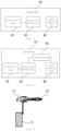
- Fig. 2 is a schematic structural view according to the electronic nose positioning device of the present disclosure.
- the electronic nose positioning device according to the present embodiment further includes a controller 50.
- the controller 50 can be configured to receive the scan data of the laser sensing unit 40 and cause the adjusting mechanism 30 to adjust the electronic nose 20 to the odor sampling part 61 of the object to be detected 60 based on the scan data.
- the at least one area laser sensor includes a first area laser sensor 41 and a second area laser sensor 42.
- a rectangular coordinate system can be established with reference to a side surface of the object to be detected 60, wherein the direction parallel to the side surface of the object to be detected 60 and the horizontal plane is the x direction, the direction perpendicular to the side surface of the object to be detected 60 and parallel to the horizontal plane is the y direction, and the direction perpendicular to both the x and y directions is the z direction.
- the scanning surface of the first area laser sensor 41 is a vertical scanning surface parallel to the zy plane, which can be used to collect the side profile information of the object 60 to be detected.
- the scanning area of the second area laser sensor 42 is a horizontal scanning plane parallel to the xy plane, which can be used to collect the position and motion information of the object 60 to be detected relative to the laser sensing unit 40, for example, to obtain a real-time position of the object 60 to be detected, and accordingly further calculate a speed or acceleration of the laser sensing unit 40 or the carrier 10 fixedly provided with the laser sensing unit 40 relative to the object 60 to be detected.
- the dynamic scanning process of the first area laser sensor 41 and the second area laser sensor 42 can be realized by movement of the carrier relative to the object 60 to be detected, and can be realized by movement of the first area laser sensor 41 and the second area laser sensor 42 on the carrier 10.
- the first area laser sensor 41 and the second area laser sensor 42 are located on the same side of the object 60 to be detected. That is, the second area laser sensor 42 is located on one side of the object 60 to be detected adjacent to the first area laser sensor 41. In other embodiments, referring to Fig. 5 , the second area laser sensor 42 can also be located on one side of the object 60 to be detected away from the first area laser sensor 41.
- the carrier 10 can be a gantry frame moving along the track, which can move on both sides of and over the object 60 to be detected (for example, a container), and the first area laser sensor 41 and the second area laser sensor 42 can be respectively disposed on the frame bodies of the gantry frame located on both sides of the object 60 to be detected.
- the electronic nose 20 and the adjusting mechanism 30 can be provided on the gantry frame.
- the controller 50 receives scan data of the first area laser sensor 41 and the second area laser sensor 42 and establishes a side profile image of the object 60 to be detected according to the scan data.
- the controller 50 also calculates a position of the odor sampling part 61 of the object 60 to be detected in the side profile image according to the scan data, for example, determines the horizontal distance and vertical distance from the odor sampling part 61 to the edge of the side surface of the object 60 to be detected, and then causes the adjusting mechanism 30 to adjust the electronic nose 20 to the odor sampling part 61.
- the controller 50 can calculate a position of the odor sampling part 61 of the object 60 to be detected on the side profile image based on the scan data, so that the motion range of the carrier 10 moving to the distal end of the robot arm 31 can cover a position of the odor sampling part 61. In this way, the controller 50 can further cause the robot arm 31 to adjust the sampler of the electronic nose 20 to the odor sampling part 61, for example, to make the sampler directly face towards the odor sampling part 61.
- Fig. 6 is a schematic flow chart of the electronic nose positioning method of the present disclosure.
- the electronic nose positioning method includes the steps of:
- the object to be detected 60 includes a container and the odor sampling part 61 is a vent hole of the container
- the odor sampling part 61 is a vent hole of the container
- the electronic nose can be adjusted to the vent hole according to the specific position, so that the electronic nose can collect the odor in the vent hole, thereby realizing the relevant inspection of the container.
- control of the laser sensing unit 40, the adjusting mechanism 30 and the electronic nose 20 can be implemented by the controller within the electronic nose positioning device, the remote controller of the operator or the remote-control platform.
- the laser sensing unit 40 comprises a first area laser sensor 41 whose scanning surface is a vertical scanning surface and a second area laser sensor 42 whose scanning surface is a horizontal scanning surface, and the step 100 includes steps 110 and 120.
- step 110 the side profile information of the object 60 to be detected is collected by the first area laser sensor 41.
- step 120 the position and motion information of the object to be detected 60 relative to the electronic nose 20 is collected by the second area laser sensor 42.
- the step 110 and the step 120 can be interchanged in sequence and can be performed simultaneously.
- the step 200 includes step 210 and step 220.
- step 210 a side profile image of the object 60 to be detected is established according to the scan data of the first area laser sensor 41 and the second area laser sensor 42.
- step 220 a position of the odor sampling part 61 in the side profile image is calculated to determine a horizontal distance and a vertical distance of the odor sampling part 61 relative to an edge of the object 60 to be detected.
- a rectangular profile image of the side surface of the container is established, and the edge position of the side surface of the container and the specific position of the vent hole on the side surface of the container can be clearly identified from the image.
- This position can be defined by the distance from the edge position of the side surface of the container.
- the position of the vent hole is defined by a horizontal distance L between the vent hole and the edges on both sides in a vertical direction, as well as a vertical distance H between the vent hole and the bottom edge of the side surface of the container or the flat surface or ground where the container is placed.
- first area laser sensor 41 and the second area laser sensor 42 can also be used to determine the distance of the carrier 10 relative to the object 60 to be detected, so that the controller causes the carrier 10 to move to a position closer to the object 60 to be detected, thereby facilitating adjusting the sampling position of the electronic nose 20 by the adjusting mechanism 30.
- the carrier 10 is movable.
- the electronic nose 20 includes a host 21 and a sampler 22.
- the host 21 is disposed on the carrier, and the adjusting mechanism 30 includes a robot arm 31, which is disposed on the carrier 10 or the host 21, wherein the sampler 22 is disposed at a distal end of the robot arm 31.
- the step 300 can include step 310 to step 330.
- step 310 according to the position of the odor sampling part 61 in the side profile image, the carrier is caused to move to a position that the motion range of the distal end of the robot arm 31 can cover the odor sampling part 61.
- the carrier is caused to move to a position that the motion range of the distal end of the robot arm 31 can cover the odor sampling part 61.
- a more accurate positioning process of the electronic nose sampler can be implemented by the steps 320 and 330.
- the motion range of the distal end of the robot arm 31 can also cover the position of the odor sampling part 61, and thus the step 310 can be omitted.
- the target position of the robot arm 31 can be determined by transformation of the coordinate system according to the position of the odor sampling part 61 in the side profile image. For example, it is possible to set the o point of the foregoing coordinate system on the second area laser sensor 42, and determine the x-coordinate value and the z-coordinate value in the foregoing coordinate system according to the distances between the odor sampling part 61 and the side edge and between the odor sampling part 61 and the bottom surface measured by the second area laser sensor 42 and the first area laser sensor 41, thereby further determining the coordinate position of the odor sampling part 61 relative to the second area laser sensor 42.
- the coordinate position of the odor sampling part 61 relative to the second area laser sensor 42 is converted to the coordinate system of the robot arm 31, to determine the target position of a distal end of the robot arm 31.
- step 330 the distal end of the robot arm 31 can be caused to move to the target position according to the target position, so that the sampling range of the sampler 22 covers the odor sampling part 61.
- it can be determined whether the sampler of the electronic nose is in place according to the feedback information of the detection switch, and after it is determined to be in place, the gas sampling process is maintained for a preset time until the end of the sampling.
Landscapes
- Chemical & Material Sciences (AREA)
- Physics & Mathematics (AREA)
- General Physics & Mathematics (AREA)
- Health & Medical Sciences (AREA)
- Life Sciences & Earth Sciences (AREA)
- Engineering & Computer Science (AREA)
- Pathology (AREA)
- Immunology (AREA)
- Analytical Chemistry (AREA)
- Biochemistry (AREA)
- General Health & Medical Sciences (AREA)
- Food Science & Technology (AREA)
- Medicinal Chemistry (AREA)
- Combustion & Propulsion (AREA)
- Acoustics & Sound (AREA)
- Computer Vision & Pattern Recognition (AREA)
- Robotics (AREA)
- Mechanical Engineering (AREA)
- Length Measuring Devices By Optical Means (AREA)
- Manipulator (AREA)
- Sampling And Sample Adjustment (AREA)
- Investigating Or Analysing Materials By Optical Means (AREA)
Description
- The present disclosure relates to the field of detection, and in particular, to an electronic nose positioning device and positioning method.
- The electronic nose, which is also referred to as an odor scanner, is a detection instrument which may be applied to fields such as environmental monitoring (such as monitoring toxic and harmful gases), product quality detection (such as quality monitoring of animal and plant products), medical diagnosis, and explosive detection (such as volatile hazard detection). In the related art, the portable electronic nose may be manually operated by a person, but such manner has relatively limited operational scenes.
- For odor inspection of enclosed devices such as containers, it is necessary to perform an inhalation inspection by means of an electronic nose after the container is opened. In the case where the container is not opened, it is necessary to force an electronic nose sampler into the door of the container to perform an inhalation inspection. Therefore, the related art has an inspection process which is relatively complicated and consumes a relatively long time, and the sampler is easily damaged during the inspection process.
- There have been several patent documents or journal articles issued that cover variations of the electronic nose positioning device and positioning method. For example, the
German patent DE19710913A1 discloses a system to test foreign gas in and remove container. The system includes a gas analyzer and a gas removal system. Containers, such as bottles, standing on a conveyor unit are passed under the gas removal system, to take the gas leaving the containers. A measuring system is provided to determine the individual height of the containers upstream from the gas removal system. A height adjusting unit is provided to lower or raise the gas removal system. A control unit controls the height adjusting unit, according to a signal given by the measuring system. The control unit acts such that the distance between the individual containers and the gas removal system is maintained at a constant predetermined value. - Likewise, the conference paper "Creating gas concentration gridmaps with a mobile robot" in PROCEEDINGS OF THE 2003 IEEE/RSJ INTERNATIONAL CONFERENCE ON INTELLIGENT ROBOTS AND SYSTEMS discloses a mobile robot for creating gas concentration gridmaps. The location estimates required for map building were obtained by the external, vision-based absolute positioning system W-CAPS. The experiments were performed with a Koala mobile robot equipped with the Mark III mobile nose, comprising 6 tin oxide sensors manufactured by Figaro. To record the position of the robot the vision-based absolute positioning system W-CAPS was applied, which tracks a distinctly colored object mounted on top of the robot.
- The conference paper "Soil sensing survey robots based on electronic nose" in 2013 13TH INTERNATIONAL CONFERENCE ON CONTROL, AUTOMATION AND SYSTEMS (ICCAS 2013), IEEE discloses a soil sensing survey robot. The e-nose system equipped on this robot was operated under real situation at four location, namely, inside a floor room, lawn, dry ground, and vineyard row, to identify the different characteristics of each place. The e-nose robot moved slowly along the selection path with a velocity of 0.1 meter/second, while fan number 1 and 2 were flowing out to make sure that the most of air flow was from the specific ground. The navigation system of the robot is based on the APM rover Mission planer. Two ultrasonic distance-measuring sensors, gyromagnetic, and accelerometer were used to check and avoid the obstacle in the path of robot movement with real time vision from live radio camera sent to the computer using 5.4 GHz radio frequencies.
-
U.S. Patent Application Publication No. 20170369168 discloses an unmanned aerial vehicle for scent analysis. The unmanned aerial vehicle includes a sensor array to sample ambient air in a location to detect an odor, a pattern recognition unit coupled to a database to identify the odor, wherein the odor is compared to identification information stored in the database, and a mapping unit to estimate an assessment value associated with the odor and to generate an instruction to one or more components of the unmanned aerial vehicle to perform a function when the assessment value exceeds a predetermined threshold value, wherein the function includes activating one or more feedback outputs on the unmanned aerial vehicle. -
U.S. Patent Application Publication No. 20170184392 discloses a vehicle guidance system, a method for orientating a vehicle, and an inspection vehicle. The vehicle guidance system includes at least two separate reference devices; a laser scanner device, configured to emit a laser beam signals and scan a sectorial region with the laser beam so as to measure a distance of a straight connection line for connecting the laser scanner device to any of the at least two separate reference devices, and an angle between the corresponding straight connection line and a vehicle body of the vehicle, or an angle between the straight connection lines; a processor, configured to process and store data, and to determine whether the orientation of the vehicle body in real time is deviating from an initial orientation of the vehicle body upon the system starts to operate or not, in accordance with the sensed results by the laser scanner device. - In view of this, the embodiments of the present disclosure provide an electronic nose positioning device and positioning method, which can simplify the inspection process of the electronic nose.
- In one aspect of the present disclosure, an electronic nose positioning device is provided. The electronic nose positioning device includes: a carrier; an electronic nose disposed on the carrier; an adjusting mechanism configured to adjust the electronic nose to an odor sampling part of an object to be detected; and a laser sensing unit disposed on the carrier, the electronic nose, or the adjusting mechanism, and configured to scan the object to be detected, so as to determine a position of an odor sampling part of the object to be detected, wherein the laser sensing unit includes at least one area laser sensor, and the at least one area laser sensor includes: a first area laser sensor, whose scanning surface is a vertical scanning surface, configured to obtain side profile information of the object to be detected; and a second area laser sensor, whose scanning surface is a horizontal scanning surface, configured to obtain position and motion information of the object to be detected relative to the electronic nose; wherein the electronic nose positioning device further comprises: a controller configured to receive scan data of the first area laser sensor and the second area laser sensor and establish a side profile image of the object to be detected according to the scan data; wherein the controller is configured to calculate a position of the odor sampling part in the side profile image to determine a horizontal distance and a vertical distance of the odor sampling part relative to the object to be detected, and to cause the adjusting mechanism to adjust the electronic nose to the odor sampling part.
- In some embodiments, the carrier is movable.
- In some embodiments, the electronic nose includes a host and a sampler, the adjusting mechanism includes: a robot arm disposed on the carrier or the host, and the sampler is disposed at a distal end of the robot arm.
- In some embodiments, the carrier is movable, the electronic nose includes a host and a sampler, and the adjusting mechanism includes: a robot arm disposed on the carrier or the host, and the sampler is disposed at a distal end of the robot arm; wherein the controller is configured to calculate a position of the odor sampling part of the object to be detected in the side profile image according to the scan data and cause the carrier to move to a position which a motion range of the distal end of the robot arm is capable of covering the odor sampling part.
- In some embodiments, the second area laser sensor is located on one side of the object to be detected adjacent to the first area laser sensor or located on one side of the object to be detected away from the first area laser sensor.
- In some embodiments, the object to be detected includes a container, wherein the adjusting mechanism is configured to adjust the electronic nose to a vent hole of a container, the laser sensing unit is configured to scan the container, so as to determine a position of the vent hole of the container.
- In one aspect of the present disclosure, an electronic nose positioning method is provided. The electronic nose positioning method includes the steps of: scanning an object to be detected by a laser sensing unit; determining a position of an odor sampling part of the object to be detected according to scan data of the laser sensing unit; and adjusting an electronic nose to the odor sampling part of the object to be detected by an adjusting mechanism, wherein the laser sensing unit includes a first area laser sensor whose scanning surface is a vertical scanning surface and a second area laser sensor whose scanning surface is a horizontal scanning surface, and the step of scanning the object to be detected by the laser sensing unit includes: obtaining a side profile information of the object to be detected by the first area laser sensor; and obtaining position and motion information of the object to be detected relative to the electronic nose by the second area laser sensor; wherein the step of determining a position of an odor sampling part of the object to be detected comprises: establishing a side profile image of the object to be detected according to the scan data of the first area laser sensor and the second area laser sensor; calculating a position of the odor sampling part in the side profile image to determine a horizontal distance and a vertical distance of the odor sampling part relative to the object to be detected; and causing the adjusting mechanism to adjust the electronic nose to the odor sampling part.
- In some embodiments, the electronic nose includes a host and a sampler, the host is disposed on a movable carrier, the adjusting mechanism includes a robot arm disposed on the carrier or the host, and the sampler is disposed at a distal end of the robot arm; the step of adjusting an electronic nose includes: causing the carrier to move to a position which a motion range of the distal end of the robot arm is capable of covering the odor sampling part according to a position of the odor sampling part on the side profile image; determining a target position of the robot arm by transformation of a coordinate system according to the position of the odor sampling part in the side profile image; and causing the distal end of the robot arm to move to the target position according to the target position, so that a sampling range of the sampler covers the odor sampling part.
- In some embodiments, the object to be detected includes a container, wherein the odor sampling part is a vent hole of the container.
- Therefore, according to the embodiments of the present disclosure, the position of the odor sampling part of the object to be detected is determined by scanning the object to be detected through a laser sensing unit, and the electronic nose is adjusted to the odor sampling part by an adjusting mechanism, so that the electronic nose can perform odor sampling at the odor sampling part, thereby meeting the relevant inspection requirements. The scanning of the laser sensing unit and adjustment of the adjusting mechanism can effectively simplify the inspection process of the electronic nose, reduce the time consumed by the inspection process, and improve the inspection efficiency.
- The accompanying drawings, which constitute part of this specification, illustrate exemplary embodiments of the present disclosure and, together with this specification, serve to explain the principles of the present disclosure.
- The present disclosure may be more clearly understood from the following detailed description with reference to the accompanying drawings, in which:
-
Fig. 1 is a schematic structural view according to some embodiments of the electronic nose positioning device of the present disclosure; -
Fig. 2 is a schematic structural view according to other embodiments of the electronic nose positioning device of the present disclosure; -
Fig. 3 is a schematic view of a mounting structure of an electronic nose and a robot arm according to some embodiments of the electronic nose positioning device of the present disclosure; -
Fig. 4 is a schematic view of scanning an object to be detected by a laser sensing unit according to some embodiments of the electronic nose positioning device of the present disclosure; -
Fig. 5 is a schematic view of scanning an object to be detected by a laser sensing unit according to other embodiments of the electronic nose positioning device of the present disclosure; -
Fig. 6 is a schematic flow chart according to some embodiments of the electronic nose positioning method of the present disclosure; -
Fig. 7 is a schematic flow chart of scanning an object to be detected according to some embodiments of the electronic nose positioning method of the present disclosure; -
Fig. 8 is a schematic flow chart of determining an odor sampling part according to some embodiments of the electronic nose positioning method of the present disclosure; -
Fig. 9 is a schematic flow chart of adjusting a sampling position of an electronic nose according to some embodiments of the electronic nose positioning method of the present disclosure. - It should be understood that the dimensions of the various parts shown in the accompanying drawings are not drawn according to the actual scale. In addition, the same or similar reference signs are used to denote the same or similar components.
- Various exemplary embodiments of the present disclosure will now be described in detail with reference to the accompanying drawings. The description of the exemplary embodiments is merely illustrative and is in no way intended as a limitation to the present disclosure and application or use thereof. The present disclosure may be implemented in many different forms, which are not limited to the embodiments described herein. These embodiments are provided to make the present disclosure thorough and complete, and fully convey the scope of the present disclosure to those skilled in the art. It should be noted that, unless otherwise specified, the relative arrangements of the components and steps expounded in these embodiments should be construed as merely illustrative, rather than as a delimitation.
- The words "first", "second", and similar words used in the present disclosure do not denote any order, quantity or importance, but merely serve to distinguish different parts. Such similar words as "including" or "containing" mean that the element preceding the word encompasses the elements enumerated after the word, and does not exclude the possibility of encompassing other elements as well. The terms "up", "down", "left", "right", or the like are used only to represent a relative positional relationship, and the relative positional relationship may be changed correspondingly if the absolute position of the described object changes.
- In the present disclosure, when it is described that a particular device is located between the first device and the second device, there may be an intermediate device between the particular device and the first device or the second device, and alternatively, there may be no intermediate device. When it is described that a particular device is connected to other devices, the particular device may be directly connected to said other devices without an intermediate device, and alternatively, may not be directly connected to said other devices but with an intermediate device.
- All the terms (including technical and scientific terms) used in the present disclosure have the same meanings as understood by those skilled in the art of the present disclosure unless otherwise defined. It should also be understood that terms as defined in general dictionaries, unless explicitly defined herein, should be interpreted as having meanings that are consistent with their meanings in the context of the relevant art, and not to be interpreted in an idealized or extremely formalized sense.
- Techniques, methods, and apparatus known to those of ordinary skill in the relevant art may not be discussed in detail.
- According to one aspect of the present disclosure, an electronic nose positioning device is provided. The electronic nose positioning device include: a carrier; an electronic nose disposed on the carrier; an adjusting mechanism configured to adjust the electronic nose to an odor sampling part of an object to be detected; and a laser sensing unit disposed on the carrier, the electronic nose, or the adjusting mechanism, and configured to scan the object to be detected, so as to determine a position of an odor sampling part of the object to be detected.
- Referring to
Fig. 1 , the electronic nose positioning device includes: acarrier 10, anelectronic nose 20, anadjusting mechanism 30, and alaser sensing unit 40. Thecarrier 10 may carry various functional devices in the electronic nose positioning device. In some embodiments, thecarrier 10 is movable. For example, a running gear is provided at the bottom of thecarrier 10 so that it can move on the ground or the surface of a platform, and can implement transition of the device, dynamic scanning of thelaser sensor unit 40 in motion, and aid to adjust theelectronic nose 20 to anodor sampling part 61 of anobject 60 to be detected. In other embodiments, thecarrier 10 can be fixed. Thecarrier 10 can also be a frame adjusted along a track, such as a gantry frame. - The
electronic nose 20 is disposed on thecarrier 10. Referring toFig. 3 , in some embodiments, theelectronic nose 20 can include ahost 21 and asampler 22. Thehost 21 can be fixed on thecarrier 10. In other embodiments, it can also be integrated with thecarrier 10. That is, thehost 21 also serves as a carrier to carry other functional devices, and a moving gear can be correspondingly provided at the bottom of thehost 21. - The
adjusting mechanism 30 can adjustelectronic nose 20 to anodor sampling part 61 of anobject 60 to be detected. Referring toFig. 3 , in some embodiments, the adjustingmechanism 30 can include arobot arm 31. Therobot arm 31 can be disposed on thecarrier 10 or thehost 21, and thesampler 22 is disposed at a distal end of therobot arm 31. Therobot 31 moves in multiple degrees of freedom so that the spatial position and sampling direction of thesampler 22 can be adjusted within a wide range. In other embodiments, the adjustingmechanism 30 can also be in other forms. For example, the adjustingmechanism 30 includes a lifting mechanism and a horizontal feeding mechanism to adjust the spatial position of thesampler 22. - The
laser sensing unit 40 can be disposed on thecarrier 10, theelectronic nose 20, or theadjusting mechanism 30. In order to improve scanning efficiency, thelaser sensing unit 40 includes at least one area laser sensor. Thelaser sensing unit 40 can be fixed relative to thecarrier 10, or can move on thecarrier 10 along a set direction to achieve the scanning function in a certain range. Thelaser sensing unit 40 can scan theobject 60 to be detected to determine a position of theodor sampling part 61 of theobject 60 to be detected. Here, theobject 60 to be detected can be various large or medium-and-small objects or areas, such as containers, trunks, parcels, vehicles and warehouses. Theodor sampling part 61 is an area on the surface of theobject 60 to be detected that communicates an internal odor space, such as a vent hole of a container, a zipper of a trunk or a transom of a warehouse. - In the present embodiments, the position of the odor sampling part of the object to be detected is determined by scanning the object to be detected through a laser sensing unit, and the electronic nose is adjusted to odor sampling part by an adjusting mechanism, so that the electronic nose can perform odor sampling at the odor sampling part, thereby meeting the relevant inspection requirements. Compared with the inspection process in the related art, the scanning of the laser sensing unit and adjustment of the adjusting mechanism can effectively simplify the inspection process of the electronic nose, reduce the time consumed by the inspection process, and improve the inspection efficiency.
-
Fig. 2 is a schematic structural view according to the electronic nose positioning device of the present disclosure. The electronic nose positioning device according to the present embodiment further includes acontroller 50. Thecontroller 50 can be configured to receive the scan data of thelaser sensing unit 40 and cause theadjusting mechanism 30 to adjust theelectronic nose 20 to theodor sampling part 61 of the object to be detected 60 based on the scan data. - Referring to
Fig. 4 , the at least one area laser sensor includes a firstarea laser sensor 41 and a secondarea laser sensor 42. InFig. 4 , a rectangular coordinate system can be established with reference to a side surface of the object to be detected 60, wherein the direction parallel to the side surface of the object to be detected 60 and the horizontal plane is the x direction, the direction perpendicular to the side surface of the object to be detected 60 and parallel to the horizontal plane is the y direction, and the direction perpendicular to both the x and y directions is the z direction. In this way, the scanning surface of the firstarea laser sensor 41 is a vertical scanning surface parallel to the zy plane, which can be used to collect the side profile information of theobject 60 to be detected. The scanning area of the secondarea laser sensor 42 is a horizontal scanning plane parallel to the xy plane, which can be used to collect the position and motion information of theobject 60 to be detected relative to thelaser sensing unit 40, for example, to obtain a real-time position of theobject 60 to be detected, and accordingly further calculate a speed or acceleration of thelaser sensing unit 40 or thecarrier 10 fixedly provided with thelaser sensing unit 40 relative to theobject 60 to be detected. - The dynamic scanning process of the first
area laser sensor 41 and the secondarea laser sensor 42 can be realized by movement of the carrier relative to theobject 60 to be detected, and can be realized by movement of the firstarea laser sensor 41 and the secondarea laser sensor 42 on thecarrier 10. - In
Fig. 4 , the firstarea laser sensor 41 and the secondarea laser sensor 42 are located on the same side of theobject 60 to be detected. That is, the secondarea laser sensor 42 is located on one side of theobject 60 to be detected adjacent to the firstarea laser sensor 41. In other embodiments, referring toFig. 5 , the secondarea laser sensor 42 can also be located on one side of theobject 60 to be detected away from the firstarea laser sensor 41. Correspondingly, thecarrier 10 can be a gantry frame moving along the track, which can move on both sides of and over theobject 60 to be detected (for example, a container), and the firstarea laser sensor 41 and the secondarea laser sensor 42 can be respectively disposed on the frame bodies of the gantry frame located on both sides of theobject 60 to be detected. Correspondingly, theelectronic nose 20 and theadjusting mechanism 30 can be provided on the gantry frame. - The
controller 50 receives scan data of the firstarea laser sensor 41 and the secondarea laser sensor 42 and establishes a side profile image of theobject 60 to be detected according to the scan data. Thecontroller 50 also calculates a position of theodor sampling part 61 of theobject 60 to be detected in the side profile image according to the scan data, for example, determines the horizontal distance and vertical distance from theodor sampling part 61 to the edge of the side surface of theobject 60 to be detected, and then causes theadjusting mechanism 30 to adjust theelectronic nose 20 to theodor sampling part 61. - If the current position of the
electronic nose 20 is far from theodor sampling part 61, thecontroller 50 can calculate a position of theodor sampling part 61 of theobject 60 to be detected on the side profile image based on the scan data, so that the motion range of thecarrier 10 moving to the distal end of therobot arm 31 can cover a position of theodor sampling part 61. In this way, thecontroller 50 can further cause therobot arm 31 to adjust the sampler of theelectronic nose 20 to theodor sampling part 61, for example, to make the sampler directly face towards theodor sampling part 61. - With reference to the above-described embodiments of the electronic nose positioning device, the present disclosure also provides a plurality of embodiments of the electronic nose positioning method.
Fig. 6 is a schematic flow chart of the electronic nose positioning method of the present disclosure. InFig. 6 , the electronic nose positioning method includes the steps of: - step 100: scanning an
object 60 to be detected by alaser sensing unit 40; - step 200: determining a position of an
odor sampling part 61 of theobject 60 to be detected according to scan data of thelaser sensing unit 40. - step 300: adjusting an
electronic nose 20 to theodor sampling part 61 of theobject 60 to be detected by anadjusting mechanism 30. - Still taking as an example that the object to be detected 60 includes a container and the
odor sampling part 61 is a vent hole of the container, when there is a need to inspect the container, it is possible to first scan the side surface of the container by thelaser sensing unit 40, and determine the specific position of the vent hole of the container on the side surface. Then, the electronic nose can be adjusted to the vent hole according to the specific position, so that the electronic nose can collect the odor in the vent hole, thereby realizing the relevant inspection of the container. - In the above-described
steps 100 to 300, the control of thelaser sensing unit 40, the adjustingmechanism 30 and theelectronic nose 20 can be implemented by the controller within the electronic nose positioning device, the remote controller of the operator or the remote-control platform. - Referring to
Fig. 7 , thelaser sensing unit 40 comprises a firstarea laser sensor 41 whose scanning surface is a vertical scanning surface and a secondarea laser sensor 42 whose scanning surface is a horizontal scanning surface, and thestep 100 includessteps step 110, the side profile information of theobject 60 to be detected is collected by the firstarea laser sensor 41. Instep 120, the position and motion information of the object to be detected 60 relative to theelectronic nose 20 is collected by the secondarea laser sensor 42. Thestep 110 and thestep 120 can be interchanged in sequence and can be performed simultaneously. - Referring to
Fig. 8 , thestep 200 includesstep 210 andstep 220. Instep 210, a side profile image of theobject 60 to be detected is established according to the scan data of the firstarea laser sensor 41 and the secondarea laser sensor 42. Instep 220, a position of theodor sampling part 61 in the side profile image is calculated to determine a horizontal distance and a vertical distance of theodor sampling part 61 relative to an edge of theobject 60 to be detected. - For example, a rectangular profile image of the side surface of the container is established, and the edge position of the side surface of the container and the specific position of the vent hole on the side surface of the container can be clearly identified from the image. This position can be defined by the distance from the edge position of the side surface of the container. For example, the position of the vent hole is defined by a horizontal distance L between the vent hole and the edges on both sides in a vertical direction, as well as a vertical distance H between the vent hole and the bottom edge of the side surface of the container or the flat surface or ground where the container is placed.
- In addition, the first
area laser sensor 41 and the secondarea laser sensor 42 can also be used to determine the distance of thecarrier 10 relative to theobject 60 to be detected, so that the controller causes thecarrier 10 to move to a position closer to theobject 60 to be detected, thereby facilitating adjusting the sampling position of theelectronic nose 20 by the adjustingmechanism 30. - In
Fig. 3 , thecarrier 10 is movable. Theelectronic nose 20 includes ahost 21 and asampler 22. Thehost 21 is disposed on the carrier, and theadjusting mechanism 30 includes arobot arm 31, which is disposed on thecarrier 10 or thehost 21, wherein thesampler 22 is disposed at a distal end of therobot arm 31. On such basis, referring toFig. 9 , in some embodiments, thestep 300 can include step 310 to step 330. - In
step 310, according to the position of theodor sampling part 61 in the side profile image, the carrier is caused to move to a position that the motion range of the distal end of therobot arm 31 can cover theodor sampling part 61. In such step, there is just need for causing the carrier to move to the position that the motion range of the distal end of therobot arm 31 can cover theodor sampling part 61, and no need to make accurate movement of the carrier in place. Thus, it is equivalent to a fuzzy positioning process. A more accurate positioning process of the electronic nose sampler can be implemented by thesteps - Of course, if the carrier is in a short distance from the
odor sampling part 61, even if the carrier does not move, the motion range of the distal end of therobot arm 31 can also cover the position of theodor sampling part 61, and thus thestep 310 can be omitted. - In
step 320, the target position of therobot arm 31 can be determined by transformation of the coordinate system according to the position of theodor sampling part 61 in the side profile image. For example, it is possible to set the o point of the foregoing coordinate system on the secondarea laser sensor 42, and determine the x-coordinate value and the z-coordinate value in the foregoing coordinate system according to the distances between theodor sampling part 61 and the side edge and between theodor sampling part 61 and the bottom surface measured by the secondarea laser sensor 42 and the firstarea laser sensor 41, thereby further determining the coordinate position of theodor sampling part 61 relative to the secondarea laser sensor 42. Then, according to a positional relationship between the secondarea laser sensor 42 and therobot arm 31, the coordinate position of theodor sampling part 61 relative to the secondarea laser sensor 42 is converted to the coordinate system of therobot arm 31, to determine the target position of a distal end of therobot arm 31. - After the target position of a distal end of the
robot arm 31 is determined, instep 330, the distal end of therobot arm 31 can be caused to move to the target position according to the target position, so that the sampling range of thesampler 22 covers theodor sampling part 61. In this process, it can be determined whether the sampler of the electronic nose is in place according to the feedback information of the detection switch, and after it is determined to be in place, the gas sampling process is maintained for a preset time until the end of the sampling. - Hereto, various embodiments of the present disclosure have been described in detail. Some details well known in the art are not described to avoid obscuring the concept of the present disclosure. According to the above description, those skilled in the art would fully know how to implement the technical solutions disclosed herein.
Claims (8)
- An electronic nose positioning device, comprising:a carrier (10);an electronic nose (20) disposed on the carrier (10);an adjusting mechanism (30) configured to adjust the electronic nose (20) to an odor sampling part (61) of an object (60) to be detected;wherein the electronic nose positioning device further comprises a laser sensing unit (40) disposed on the carrier (10), the electronic nose (20), or the adjusting mechanism (30), and configured to scan the object (60) to be detected, so as to determine a position of an odor sampling part (61) of the object (60) to be detected,wherein the laser sensing unit (40) comprises at least one area laser sensor, and the at least one area laser sensor comprises:a first area laser sensor (41), whose scanning surface is a vertical scanning surface, configured to obtain side profile information of the object (60) to be detected; anda second area laser sensor (42), whose scanning surface is a horizontal scanning surface, configured to obtain position and motion information of the object (60) to be detected relative to the electronic nose (20);wherein the electronic nose positioning device further comprises:a controller (50) configured to receive scan data of the first area laser sensor (41) and the second area laser sensor (42) and establish a side profile image of the object (60) to be detected according to the scan data;wherein the controller (50) is configured to calculate a position of the odor sampling part (61) in the side profile image to determine a horizontal distance and a vertical distance of the odor sampling part (61) relative to the object (60) to be detected, and to cause the adjusting mechanism (30) to adjust the electronic nose (20) to the odor sampling part (61).
- The electronic nose positioning device according to claim 1, wherein the carrier (10) is movable.
- The electronic nose positioning device according to claim 1, wherein the electronic nose (20) comprises a host (21) and a sampler (22), the adjusting mechanism (30) comprises: a robot arm (31) disposed on the carrier (10) or the host (21), and the sampler (22) is disposed at a distal end of the robot arm (31).
- The electronic nose positioning device according to claim 1, wherein the carrier (10) is movable, the electronic nose (20) comprises a host (21) and a sampler (22), the adjusting mechanism (30) comprises: a robot arm (31) disposed on the carrier (10) or the host (21), and the sampler (22) is disposed at a distal end of the robot arm (31); and
wherein the controller (50) is configured to calculate a position of the odor sampling part (61) of the object (60) to be detected in the side profile image according to the scan data and cause the carrier (10) to move to a position which a motion range of the distal end of the robot arm (31) is capable of covering the odor sampling part (61). - The electronic nose positioning device according to claim 1, wherein the second area laser sensor (42) is configured to be located on one side of the object (60) to be detected adjacent to the first area laser sensor (41) or located on one side of the object (60) to be detected away from the first area laser sensor (41).
- The electronic nose positioning device according to claim 1, wherein the adjusting mechanism (30) is configured to adjust the electronic nose (20) to a vent hole of a container, the laser sensing unit (40) is configured to scan the container, so as to determine a position of the vent hole of the container.
- An electronic nose positioning method, comprising the steps of:scanning an object (60) to be detected by a laser sensing unit (40) ;determining a position of an odor sampling part (61) of the object (60) to be detected according to scan data of the laser sensing unit (40); andadjusting an electronic nose (20) to the odor sampling part (61) of the object (60) to be detected by an adjusting mechanism (30), wherein the laser sensing unit (40) comprises a first area laser sensor (41) whose scanning surface is a vertical scanning surface and a second area laser sensor (42) whose scanning surface is a horizontal scanning surface, and the step of scanning the object (60) to be detected by the laser sensing unit (40) comprises:obtaining a side profile information of the object (60) to be detected by the first area laser sensor (41); andobtaining position and motion information of the object (60) to be detected relative to the electronic nose (20) by the second area laser sensor (42);wherein the step of determining a position of an odor sampling part (61) of the object (60) to be detected comprises:establishing a side profile image of the object (60) to be detected according to the scan data of the first area laser sensor (41) and the second area laser sensor (42);calculating a position of the odor sampling part (61) in the side profile image to determine a horizontal distance and a vertical distance of the odor sampling part (61) relative to the object (60) to be detected; andcausing the adjusting mechanism (30) to adjust the electronic nose (20) to the odor sampling part (61).
- The electronic nose positioning method according to claim 7, wherein the electronic nose (20) comprises a host (21) and a sampler (22), the host (21) is disposed on a movable carrier, the adjusting mechanism (30) comprises a robot arm (31) disposed on the carrier or the host (21), and the sampler (22) is disposed at a distal end of the robot arm (31);
the step of adjusting an electronic nose (20) comprises:causing the carrier (10) to move to a position which a motion range of the distal end of the robot arm (31) is capable of covering the odor sampling part (61) according to a position of the odor sampling part (61) in the side profile image;determining a target position of the robot arm (31) by transformation of a coordinate system according to the position of the odor sampling part (61) in the side profile image; andcausing the distal end of the robot arm (31) to move to the target position according to the target position, so that a sampling range of the sampler (22) covers the odor sampling part (61).
Applications Claiming Priority (1)
| Application Number | Priority Date | Filing Date | Title |
|---|---|---|---|
| CN201910108228.5A CN109682934B (en) | 2019-02-03 | 2019-02-03 | Electronic nose positioning device and positioning method |
Publications (2)
| Publication Number | Publication Date |
|---|---|
| EP3690390A1 EP3690390A1 (en) | 2020-08-05 |
| EP3690390B1 true EP3690390B1 (en) | 2025-01-01 |
Family
ID=66195513
Family Applications (1)
| Application Number | Title | Priority Date | Filing Date |
|---|---|---|---|
| EP20155081.1A Active EP3690390B1 (en) | 2019-02-03 | 2020-02-03 | Electronic nose positioning device and positioning method |
Country Status (2)
| Country | Link |
|---|---|
| EP (1) | EP3690390B1 (en) |
| CN (1) | CN109682934B (en) |
Families Citing this family (10)
| Publication number | Priority date | Publication date | Assignee | Title |
|---|---|---|---|---|
| CN110194298A (en) * | 2019-05-24 | 2019-09-03 | 珠海格力智能装备有限公司 | Method and device for determining quality of article |
| CN112346137B (en) * | 2019-08-09 | 2022-11-11 | 同方威视技术股份有限公司 | Inspection station and inspection method |
| CN111174696B (en) * | 2019-11-30 | 2022-04-15 | 河北科技大学 | A laser-assisted calibration method based on CCD sensor |
| CN110940323B (en) * | 2019-12-30 | 2025-04-18 | 王中原 | A method and device for assisting positioning of indoor environment detection points |
| CN114689390A (en) * | 2020-12-31 | 2022-07-01 | 同方威视技术股份有限公司 | Gas sampling device and sampling method |
| CN114689579A (en) * | 2020-12-31 | 2022-07-01 | 清华大学 | Automatic closure verification and handling apparatus and method |
| CN114689358A (en) * | 2020-12-31 | 2022-07-01 | 清华大学 | Contraband detection robot and detection method |
| CN114813250A (en) * | 2021-01-22 | 2022-07-29 | 天津海关工业产品安全技术中心 | Gas collection control method, device and system and robot |
| CN112816479B (en) * | 2021-01-22 | 2025-10-17 | 同方威视技术股份有限公司 | Sniffing device and inspection method thereof |
| CN115267051A (en) * | 2022-06-10 | 2022-11-01 | 中国汽车技术研究中心有限公司 | System and method for collecting and detecting fixed-point smell in automobile cabin |
Family Cites Families (12)
| Publication number | Priority date | Publication date | Assignee | Title |
|---|---|---|---|---|
| DE19710913A1 (en) * | 1997-03-15 | 1998-09-17 | Kronseder Maschf Krones | System to test foreign gas in and remove containers, e.g. bottles |
| US7265662B2 (en) * | 2005-03-17 | 2007-09-04 | Praxair Technology, Inc. | Apparatus and method for inspecting containers |
| CN102788794A (en) * | 2012-07-30 | 2012-11-21 | 江苏大学 | Device and method for detecting pesticide residues on leaves of leaf vegetables on basis of multi-sensed information fusion |
| KR20160131278A (en) * | 2015-05-06 | 2016-11-16 | 엘지전자 주식회사 | Mobile terminal |
| CN104931506B (en) * | 2015-06-05 | 2016-07-27 | 天津大学 | A kind of phone housing quality determining method |
| CN105522988B (en) * | 2015-12-29 | 2018-01-30 | 同方威视技术股份有限公司 | Vehicle guidance system, the method for vehicle directional and safety check vehicle |
| WO2017206142A1 (en) * | 2016-06-02 | 2017-12-07 | Henkel (China) Investment Co., Ltd. | Portable odor quantitative detector |
| US10604257B2 (en) * | 2016-06-28 | 2020-03-31 | International Business Machines Corporation | Unmanned aerial vehicle for air sampling |
| CN106338245B (en) * | 2016-08-15 | 2019-05-10 | 南京工业大学 | Non-contact movement measuring method for workpiece |
| CN206177751U (en) * | 2016-11-10 | 2017-05-17 | 湖南理工学院 | Bean curd quality detecting device |
| CN107413672A (en) * | 2017-04-21 | 2017-12-01 | 亳州市永刚饮片厂有限公司 | Prepared slices of Chinese crude drugs hierarchy system and method |
| CN209727892U (en) * | 2019-02-03 | 2019-12-03 | 同方威视技术股份有限公司 | Electronic nose positioning device |
-
2019
- 2019-02-03 CN CN201910108228.5A patent/CN109682934B/en active Active
-
2020
- 2020-02-03 EP EP20155081.1A patent/EP3690390B1/en active Active
Also Published As
| Publication number | Publication date |
|---|---|
| CN109682934A (en) | 2019-04-26 |
| EP3690390A1 (en) | 2020-08-05 |
| CN109682934B (en) | 2023-10-24 |
Similar Documents
| Publication | Publication Date | Title |
|---|---|---|
| EP3690390A1 (en) | Electronic nose positioning device and positioning method | |
| US12475593B2 (en) | Positioning system and moving body for measuring position of moving body using image capturing apparatus | |
| CA2786407C (en) | Method and system for sensing the position of a vehicle | |
| US12475592B2 (en) | Positioning apparatus capable of measuring position of moving body using image capturing apparatus | |
| US20140132729A1 (en) | Method and apparatus for camera-based 3d flaw tracking system | |
| CN110344621A (en) | A kind of wheel points cloud detection method of optic towards intelligent garage | |
| CN109358071B (en) | The large scale equipment surface damage detection system and its method of autonomous cover type operation | |
| US20110098923A1 (en) | Method of and apparatus for creating map of artificial marks, and method and apparatus for measuring position of moving object using the map | |
| CN119510293B (en) | Tunnel Crack Detection Methods and Systems | |
| CN214954692U (en) | Greenhouse inspection robot and greenhouse environment three-dimensional monitoring system | |
| EP3924794B1 (en) | Autonomous mobile aircraft inspection system | |
| JPH07281753A (en) | Mobile robot | |
| CN115932882A (en) | A system providing 3D exploration of the environment by an autonomous robotic vehicle | |
| CN112278891B (en) | Carriage internal attitude detection method | |
| JPWO2019054209A1 (en) | Map making system and map making device | |
| Myung et al. | Robotic SHM and model-based positioning system for monitoring and construction automation | |
| CN118135136A (en) | A kind of inspection data analysis system and method based on unmanned aerial vehicle | |
| CN206563576U (en) | A kind of microrobot alignment system detected for power transformer interior fault | |
| CN112394744A (en) | Integrated unmanned aerial vehicle system | |
| CN209727892U (en) | Electronic nose positioning device | |
| KR20240030640A (en) | System and method for landing on mobile station of an unmanned aerial vehicle | |
| James et al. | On reducing the localisation error of modern mobile robotic platforms | |
| CN108803620A (en) | A kind of UWB positioning systems for robot | |
| Blanco et al. | Localization by voronoi diagrams correlation | |
| US12409952B1 (en) | Vehicles, systems, and methods for the autonomous inspection of objects |
Legal Events
| Date | Code | Title | Description |
|---|---|---|---|
| PUAI | Public reference made under article 153(3) epc to a published international application that has entered the european phase |
Free format text: ORIGINAL CODE: 0009012 |
|
| STAA | Information on the status of an ep patent application or granted ep patent |
Free format text: STATUS: THE APPLICATION HAS BEEN PUBLISHED |
|
| AK | Designated contracting states |
Kind code of ref document: A1 Designated state(s): AL AT BE BG CH CY CZ DE DK EE ES FI FR GB GR HR HU IE IS IT LI LT LU LV MC MK MT NL NO PL PT RO RS SE SI SK SM TR |
|
| AX | Request for extension of the european patent |
Extension state: BA ME |
|
| STAA | Information on the status of an ep patent application or granted ep patent |
Free format text: STATUS: REQUEST FOR EXAMINATION WAS MADE |
|
| 17P | Request for examination filed |
Effective date: 20201223 |
|
| RBV | Designated contracting states (corrected) |
Designated state(s): AL AT BE BG CH CY CZ DE DK EE ES FI FR GB GR HR HU IE IS IT LI LT LU LV MC MK MT NL NO PL PT RO RS SE SI SK SM TR |
|
| STAA | Information on the status of an ep patent application or granted ep patent |
Free format text: STATUS: EXAMINATION IS IN PROGRESS |
|
| 17Q | First examination report despatched |
Effective date: 20220804 |
|
| GRAP | Despatch of communication of intention to grant a patent |
Free format text: ORIGINAL CODE: EPIDOSNIGR1 |
|
| STAA | Information on the status of an ep patent application or granted ep patent |
Free format text: STATUS: GRANT OF PATENT IS INTENDED |
|
| RIC1 | Information provided on ipc code assigned before grant |
Ipc: G05D 1/00 20060101ALI20240716BHEP Ipc: G01N 29/265 20060101ALI20240716BHEP Ipc: G01N 29/22 20060101ALI20240716BHEP Ipc: G01N 29/02 20060101ALI20240716BHEP Ipc: G01N 33/00 20060101ALI20240716BHEP Ipc: G01N 1/22 20060101ALI20240716BHEP Ipc: G01B 11/00 20060101AFI20240716BHEP |
|
| INTG | Intention to grant announced |
Effective date: 20240725 |
|
| GRAS | Grant fee paid |
Free format text: ORIGINAL CODE: EPIDOSNIGR3 |
|
| GRAA | (expected) grant |
Free format text: ORIGINAL CODE: 0009210 |
|
| STAA | Information on the status of an ep patent application or granted ep patent |
Free format text: STATUS: THE PATENT HAS BEEN GRANTED |
|
| AK | Designated contracting states |
Kind code of ref document: B1 Designated state(s): AL AT BE BG CH CY CZ DE DK EE ES FI FR GB GR HR HU IE IS IT LI LT LU LV MC MK MT NL NO PL PT RO RS SE SI SK SM TR |
|
| REG | Reference to a national code |
Ref country code: GB Ref legal event code: FG4D |
|
| REG | Reference to a national code |
Ref country code: DE Ref legal event code: R096 Ref document number: 602020043910 Country of ref document: DE |
|
| REG | Reference to a national code |
Ref country code: CH Ref legal event code: EP |
|
| REG | Reference to a national code |
Ref country code: IE Ref legal event code: FG4D |
|
| REG | Reference to a national code |
Ref country code: LT Ref legal event code: MG9D |
|
| REG | Reference to a national code |
Ref country code: NL Ref legal event code: MP Effective date: 20250101 |
|
| REG | Reference to a national code |
Ref country code: AT Ref legal event code: MK05 Ref document number: 1756641 Country of ref document: AT Kind code of ref document: T Effective date: 20250101 |
|
| PG25 | Lapsed in a contracting state [announced via postgrant information from national office to epo] |
Ref country code: NL Free format text: LAPSE BECAUSE OF FAILURE TO SUBMIT A TRANSLATION OF THE DESCRIPTION OR TO PAY THE FEE WITHIN THE PRESCRIBED TIME-LIMIT Effective date: 20250101 |
|
| PG25 | Lapsed in a contracting state [announced via postgrant information from national office to epo] |
Ref country code: FI Free format text: LAPSE BECAUSE OF FAILURE TO SUBMIT A TRANSLATION OF THE DESCRIPTION OR TO PAY THE FEE WITHIN THE PRESCRIBED TIME-LIMIT Effective date: 20250101 |
|
| PG25 | Lapsed in a contracting state [announced via postgrant information from national office to epo] |
Ref country code: PL Free format text: LAPSE BECAUSE OF FAILURE TO SUBMIT A TRANSLATION OF THE DESCRIPTION OR TO PAY THE FEE WITHIN THE PRESCRIBED TIME-LIMIT Effective date: 20250101 |
|
| PG25 | Lapsed in a contracting state [announced via postgrant information from national office to epo] |
Ref country code: ES Free format text: LAPSE BECAUSE OF FAILURE TO SUBMIT A TRANSLATION OF THE DESCRIPTION OR TO PAY THE FEE WITHIN THE PRESCRIBED TIME-LIMIT Effective date: 20250101 |
|
| PG25 | Lapsed in a contracting state [announced via postgrant information from national office to epo] |
Ref country code: IS Free format text: LAPSE BECAUSE OF FAILURE TO SUBMIT A TRANSLATION OF THE DESCRIPTION OR TO PAY THE FEE WITHIN THE PRESCRIBED TIME-LIMIT Effective date: 20250501 Ref country code: NO Free format text: LAPSE BECAUSE OF FAILURE TO SUBMIT A TRANSLATION OF THE DESCRIPTION OR TO PAY THE FEE WITHIN THE PRESCRIBED TIME-LIMIT Effective date: 20250401 |
|
| PG25 | Lapsed in a contracting state [announced via postgrant information from national office to epo] |
Ref country code: HR Free format text: LAPSE BECAUSE OF FAILURE TO SUBMIT A TRANSLATION OF THE DESCRIPTION OR TO PAY THE FEE WITHIN THE PRESCRIBED TIME-LIMIT Effective date: 20250101 |
|
| PG25 | Lapsed in a contracting state [announced via postgrant information from national office to epo] |
Ref country code: PT Free format text: LAPSE BECAUSE OF FAILURE TO SUBMIT A TRANSLATION OF THE DESCRIPTION OR TO PAY THE FEE WITHIN THE PRESCRIBED TIME-LIMIT Effective date: 20250502 Ref country code: LV Free format text: LAPSE BECAUSE OF FAILURE TO SUBMIT A TRANSLATION OF THE DESCRIPTION OR TO PAY THE FEE WITHIN THE PRESCRIBED TIME-LIMIT Effective date: 20250101 |
|
| PG25 | Lapsed in a contracting state [announced via postgrant information from national office to epo] |
Ref country code: BG Free format text: LAPSE BECAUSE OF FAILURE TO SUBMIT A TRANSLATION OF THE DESCRIPTION OR TO PAY THE FEE WITHIN THE PRESCRIBED TIME-LIMIT Effective date: 20250101 Ref country code: GR Free format text: LAPSE BECAUSE OF FAILURE TO SUBMIT A TRANSLATION OF THE DESCRIPTION OR TO PAY THE FEE WITHIN THE PRESCRIBED TIME-LIMIT Effective date: 20250402 |
|
| PG25 | Lapsed in a contracting state [announced via postgrant information from national office to epo] |
Ref country code: AT Free format text: LAPSE BECAUSE OF FAILURE TO SUBMIT A TRANSLATION OF THE DESCRIPTION OR TO PAY THE FEE WITHIN THE PRESCRIBED TIME-LIMIT Effective date: 20250101 |
|
| PG25 | Lapsed in a contracting state [announced via postgrant information from national office to epo] |
Ref country code: CZ Free format text: LAPSE BECAUSE OF FAILURE TO SUBMIT A TRANSLATION OF THE DESCRIPTION OR TO PAY THE FEE WITHIN THE PRESCRIBED TIME-LIMIT Effective date: 20250101 |
|
| REG | Reference to a national code |
Ref country code: DE Ref legal event code: R119 Ref document number: 602020043910 Country of ref document: DE |
|
| PG25 | Lapsed in a contracting state [announced via postgrant information from national office to epo] |
Ref country code: SE Free format text: LAPSE BECAUSE OF FAILURE TO SUBMIT A TRANSLATION OF THE DESCRIPTION OR TO PAY THE FEE WITHIN THE PRESCRIBED TIME-LIMIT Effective date: 20250101 |
|
| REG | Reference to a national code |
Ref country code: CH Ref legal event code: PL |
|
| PG25 | Lapsed in a contracting state [announced via postgrant information from national office to epo] |
Ref country code: SM Free format text: LAPSE BECAUSE OF FAILURE TO SUBMIT A TRANSLATION OF THE DESCRIPTION OR TO PAY THE FEE WITHIN THE PRESCRIBED TIME-LIMIT Effective date: 20250101 |
|
| PG25 | Lapsed in a contracting state [announced via postgrant information from national office to epo] |
Ref country code: DK Free format text: LAPSE BECAUSE OF FAILURE TO SUBMIT A TRANSLATION OF THE DESCRIPTION OR TO PAY THE FEE WITHIN THE PRESCRIBED TIME-LIMIT Effective date: 20250101 |
|
| PG25 | Lapsed in a contracting state [announced via postgrant information from national office to epo] |
Ref country code: MC Free format text: LAPSE BECAUSE OF FAILURE TO SUBMIT A TRANSLATION OF THE DESCRIPTION OR TO PAY THE FEE WITHIN THE PRESCRIBED TIME-LIMIT Effective date: 20250101 |
|
| PG25 | Lapsed in a contracting state [announced via postgrant information from national office to epo] |
Ref country code: LU Free format text: LAPSE BECAUSE OF NON-PAYMENT OF DUE FEES Effective date: 20250203 Ref country code: IT Free format text: LAPSE BECAUSE OF FAILURE TO SUBMIT A TRANSLATION OF THE DESCRIPTION OR TO PAY THE FEE WITHIN THE PRESCRIBED TIME-LIMIT Effective date: 20250101 |
|
| PG25 | Lapsed in a contracting state [announced via postgrant information from national office to epo] |
Ref country code: CH Free format text: LAPSE BECAUSE OF NON-PAYMENT OF DUE FEES Effective date: 20250228 |
|
| PG25 | Lapsed in a contracting state [announced via postgrant information from national office to epo] |
Ref country code: EE Free format text: LAPSE BECAUSE OF FAILURE TO SUBMIT A TRANSLATION OF THE DESCRIPTION OR TO PAY THE FEE WITHIN THE PRESCRIBED TIME-LIMIT Effective date: 20250101 |
|
| PG25 | Lapsed in a contracting state [announced via postgrant information from national office to epo] |
Ref country code: RO Free format text: LAPSE BECAUSE OF FAILURE TO SUBMIT A TRANSLATION OF THE DESCRIPTION OR TO PAY THE FEE WITHIN THE PRESCRIBED TIME-LIMIT Effective date: 20250101 |
|
| PG25 | Lapsed in a contracting state [announced via postgrant information from national office to epo] |
Ref country code: SK Free format text: LAPSE BECAUSE OF FAILURE TO SUBMIT A TRANSLATION OF THE DESCRIPTION OR TO PAY THE FEE WITHIN THE PRESCRIBED TIME-LIMIT Effective date: 20250101 |
|
| PLBE | No opposition filed within time limit |
Free format text: ORIGINAL CODE: 0009261 |
|
| STAA | Information on the status of an ep patent application or granted ep patent |
Free format text: STATUS: NO OPPOSITION FILED WITHIN TIME LIMIT |
|
| REG | Reference to a national code |
Ref country code: BE Ref legal event code: MM Effective date: 20250228 |
|
| 26N | No opposition filed |
Effective date: 20251002 |
|
| GBPC | Gb: european patent ceased through non-payment of renewal fee |
Effective date: 20250401 |
|
| PG25 | Lapsed in a contracting state [announced via postgrant information from national office to epo] |
Ref country code: DE Free format text: LAPSE BECAUSE OF NON-PAYMENT OF DUE FEES Effective date: 20250902 |
|
| PG25 | Lapsed in a contracting state [announced via postgrant information from national office to epo] |
Ref country code: GB Free format text: LAPSE BECAUSE OF NON-PAYMENT OF DUE FEES Effective date: 20250401 |
|
| PG25 | Lapsed in a contracting state [announced via postgrant information from national office to epo] |
Ref country code: FR Free format text: LAPSE BECAUSE OF NON-PAYMENT OF DUE FEES Effective date: 20250301 |
|
| PG25 | Lapsed in a contracting state [announced via postgrant information from national office to epo] |
Ref country code: BE Free format text: LAPSE BECAUSE OF NON-PAYMENT OF DUE FEES Effective date: 20250228 |
|
| PG25 | Lapsed in a contracting state [announced via postgrant information from national office to epo] |
Ref country code: IE Free format text: LAPSE BECAUSE OF NON-PAYMENT OF DUE FEES Effective date: 20250203 |