EP3690353A1 - Verfahren zum betreiben einer thermoregulierungsanordnung, thermoregulierungsanordnung und fahrzeug - Google Patents
Verfahren zum betreiben einer thermoregulierungsanordnung, thermoregulierungsanordnung und fahrzeug Download PDFInfo
- Publication number
- EP3690353A1 EP3690353A1 EP20154222.2A EP20154222A EP3690353A1 EP 3690353 A1 EP3690353 A1 EP 3690353A1 EP 20154222 A EP20154222 A EP 20154222A EP 3690353 A1 EP3690353 A1 EP 3690353A1
- Authority
- EP
- European Patent Office
- Prior art keywords
- reaction gas
- heat transfer
- reactor device
- heat
- arrangement
- Prior art date
- Legal status (The legal status is an assumption and is not a legal conclusion. Google has not performed a legal analysis and makes no representation as to the accuracy of the status listed.)
- Granted
Links
Images


Classifications
-
- F—MECHANICAL ENGINEERING; LIGHTING; HEATING; WEAPONS; BLASTING
- F25—REFRIGERATION OR COOLING; COMBINED HEATING AND REFRIGERATION SYSTEMS; HEAT PUMP SYSTEMS; MANUFACTURE OR STORAGE OF ICE; LIQUEFACTION SOLIDIFICATION OF GASES
- F25B—REFRIGERATION MACHINES, PLANTS OR SYSTEMS; COMBINED HEATING AND REFRIGERATION SYSTEMS; HEAT PUMP SYSTEMS
- F25B17/00—Sorption machines, plants or systems, operating intermittently, e.g. absorption or adsorption type
- F25B17/08—Sorption machines, plants or systems, operating intermittently, e.g. absorption or adsorption type the absorbent or adsorbent being a solid, e.g. salt
-
- B—PERFORMING OPERATIONS; TRANSPORTING
- B60—VEHICLES IN GENERAL
- B60H—ARRANGEMENTS OF HEATING, COOLING, VENTILATING OR OTHER AIR-TREATING DEVICES SPECIALLY ADAPTED FOR PASSENGER OR GOODS SPACES OF VEHICLES
- B60H1/00—Heating, cooling or ventilating devices
- B60H1/00357—Air-conditioning arrangements specially adapted for particular vehicles
- B60H1/00385—Air-conditioning arrangements specially adapted for particular vehicles for vehicles having an electrical drive, e.g. hybrid or fuel cell
-
- B—PERFORMING OPERATIONS; TRANSPORTING
- B60—VEHICLES IN GENERAL
- B60H—ARRANGEMENTS OF HEATING, COOLING, VENTILATING OR OTHER AIR-TREATING DEVICES SPECIALLY ADAPTED FOR PASSENGER OR GOODS SPACES OF VEHICLES
- B60H1/00—Heating, cooling or ventilating devices
- B60H1/00492—Heating, cooling or ventilating devices comprising regenerative heating or cooling means, e.g. heat accumulators
- B60H1/00499—Heat or cold storage without phase change including solid bodies, e.g. batteries
-
- B—PERFORMING OPERATIONS; TRANSPORTING
- B60—VEHICLES IN GENERAL
- B60H—ARRANGEMENTS OF HEATING, COOLING, VENTILATING OR OTHER AIR-TREATING DEVICES SPECIALLY ADAPTED FOR PASSENGER OR GOODS SPACES OF VEHICLES
- B60H1/00—Heating, cooling or ventilating devices
- B60H1/02—Heating, cooling or ventilating devices the heat being derived from the propulsion plant
- B60H1/14—Heating, cooling or ventilating devices the heat being derived from the propulsion plant other than from cooling liquid of the plant
- B60H1/143—Heating, cooling or ventilating devices the heat being derived from the propulsion plant other than from cooling liquid of the plant the heat being derived from cooling an electric component, e.g. electric motors, electric circuits, fuel cells or batteries
-
- F—MECHANICAL ENGINEERING; LIGHTING; HEATING; WEAPONS; BLASTING
- F25—REFRIGERATION OR COOLING; COMBINED HEATING AND REFRIGERATION SYSTEMS; HEAT PUMP SYSTEMS; MANUFACTURE OR STORAGE OF ICE; LIQUEFACTION SOLIDIFICATION OF GASES
- F25B—REFRIGERATION MACHINES, PLANTS OR SYSTEMS; COMBINED HEATING AND REFRIGERATION SYSTEMS; HEAT PUMP SYSTEMS
- F25B41/00—Fluid-circulation arrangements
- F25B41/20—Disposition of valves, e.g. of on-off valves or flow control valves
- F25B41/28—Disposition of valves, e.g. of on-off valves or flow control valves specially adapted for sorption cycles
-
- F—MECHANICAL ENGINEERING; LIGHTING; HEATING; WEAPONS; BLASTING
- F25—REFRIGERATION OR COOLING; COMBINED HEATING AND REFRIGERATION SYSTEMS; HEAT PUMP SYSTEMS; MANUFACTURE OR STORAGE OF ICE; LIQUEFACTION SOLIDIFICATION OF GASES
- F25B—REFRIGERATION MACHINES, PLANTS OR SYSTEMS; COMBINED HEATING AND REFRIGERATION SYSTEMS; HEAT PUMP SYSTEMS
- F25B49/00—Arrangement or mounting of control or safety devices
- F25B49/04—Arrangement or mounting of control or safety devices for sorption type machines, plants or systems
- F25B49/046—Operating intermittently
-
- F—MECHANICAL ENGINEERING; LIGHTING; HEATING; WEAPONS; BLASTING
- F25—REFRIGERATION OR COOLING; COMBINED HEATING AND REFRIGERATION SYSTEMS; HEAT PUMP SYSTEMS; MANUFACTURE OR STORAGE OF ICE; LIQUEFACTION SOLIDIFICATION OF GASES
- F25B—REFRIGERATION MACHINES, PLANTS OR SYSTEMS; COMBINED HEATING AND REFRIGERATION SYSTEMS; HEAT PUMP SYSTEMS
- F25B17/00—Sorption machines, plants or systems, operating intermittently, e.g. absorption or adsorption type
- F25B17/12—Sorption machines, plants or systems, operating intermittently, e.g. absorption or adsorption type using desorption of hydrogen from a hydride
-
- F—MECHANICAL ENGINEERING; LIGHTING; HEATING; WEAPONS; BLASTING
- F25—REFRIGERATION OR COOLING; COMBINED HEATING AND REFRIGERATION SYSTEMS; HEAT PUMP SYSTEMS; MANUFACTURE OR STORAGE OF ICE; LIQUEFACTION SOLIDIFICATION OF GASES
- F25B—REFRIGERATION MACHINES, PLANTS OR SYSTEMS; COMBINED HEATING AND REFRIGERATION SYSTEMS; HEAT PUMP SYSTEMS
- F25B2600/00—Control issues
- F25B2600/01—Timing
-
- F—MECHANICAL ENGINEERING; LIGHTING; HEATING; WEAPONS; BLASTING
- F25—REFRIGERATION OR COOLING; COMBINED HEATING AND REFRIGERATION SYSTEMS; HEAT PUMP SYSTEMS; MANUFACTURE OR STORAGE OF ICE; LIQUEFACTION SOLIDIFICATION OF GASES
- F25B—REFRIGERATION MACHINES, PLANTS OR SYSTEMS; COMBINED HEATING AND REFRIGERATION SYSTEMS; HEAT PUMP SYSTEMS
- F25B2600/00—Control issues
- F25B2600/23—Time delays
-
- F—MECHANICAL ENGINEERING; LIGHTING; HEATING; WEAPONS; BLASTING
- F25—REFRIGERATION OR COOLING; COMBINED HEATING AND REFRIGERATION SYSTEMS; HEAT PUMP SYSTEMS; MANUFACTURE OR STORAGE OF ICE; LIQUEFACTION SOLIDIFICATION OF GASES
- F25B—REFRIGERATION MACHINES, PLANTS OR SYSTEMS; COMBINED HEATING AND REFRIGERATION SYSTEMS; HEAT PUMP SYSTEMS
- F25B2600/00—Control issues
- F25B2600/25—Control of valves
- F25B2600/2507—Flow-diverting valves
Definitions
- the invention relates to a method for operating a thermoregulation arrangement for temperature control (thermal regulation) of a system which is in thermal contact with the thermoregulation arrangement and which is arranged in particular within a vehicle in which reaction gas is conducted in a reaction gas system from a reaction gas source with the interposition of a temperature control arrangement into a reaction gas well
- heat is generated in at least one reactor device with reaction material in an absorption mode and then cold in a desorption mode or vice versa, wherein in the absorption mode reaction gas is absorbed by the reaction material while releasing heat and in the desorption mode reaction gas is released from it Reaction material is desorbed with heat absorption, and wherein the at least one reactor device is flowed through by a heat transfer medium for receiving the generated heat or cold, a first heat transfer circuit in the desorption mode and a second heat transfer circuit in the absorption mode, with a different, preferably higher, exit temperature of the heat transfer medium from the reactor device than in the first heat transfer circuit, with the reactor device in
- reaction systems thermochemical gas-solid reaction systems
- reaction systems wherein a reaction gas is reversibly bound to a solid as a reaction material in an exothermic, ie heat-releasing reaction (absorption). Cold can be generated in the endothermic back reaction, releasing the reaction gas (desorption) and absorbing heat from the environment.
- Suitable material pairs of the reaction system are, for example, hydrogen as the reaction gas and a metal as a solid, a metal hydride being formed in the loaded state.
- closed systems these systems are driven by a heat source and in the so-called open systems by a pressure difference in the reaction gas supply.
- thermoregulation arrangement of the type mentioned at the outset are known from US Pat DE 10 2014 109 580 B3 known. A closed system within the thermoregulation arrangement is used here.
- the invention has for its object to provide an efficiency-increasing method for operating a thermoregulation arrangement, as well as a correspondingly operable thermoregulation arrangement and a vehicle with the same.
- thermoregulation arrangement comprises in particular a correspondingly designed control device.
- the switching of the flow connections upstream and downstream of the reactor device does not take place simultaneously, but with a time offset accordingly the switching time.
- Such an asynchronous switchover has the effect that the residual volume of heat transfer medium still present in the reactor device can flow into the heat transfer circuit which is coupled to the reactor device immediately before the change. This prevents the residual volume from flowing into the heat transfer circuit which is coupled to the change and which, as a rule, has a different temperature range, at least a different outlet temperature. An entry of the heat transfer medium into the other heat transfer circuit, with a different temperature level, and an associated undesired loss of heat or "cold" can be avoided in this way.
- the heat initially stored in the reactor mass can further heat or cool the residual volume of heat transfer medium, so that a type of heat recovery can take place. Investigations by the inventors have shown that the efficiency of the system and thus the thermal output can advantageously be significantly increased.
- the changeover time is determined as a function of a throughflow time of the heat transfer medium through at least the reactor device, the changeover time preferably (at least essentially, for example taking tolerance times into account) corresponds to the throughflow time.
- the changeover time is particularly advantageous as a function of a throughflow time of the heat transfer medium of a volume to be flowed through, starting from a coupling point arranged upstream of the reactor device (e.g. formed by a first valve means) to a downstream coupling point (e.g. formed by a second valve means) ) the reactor device for flow connection with the heat transfer circuit is determined.
- the switchover time can be determined and implemented in a controller by a control device of the thermoregulation arrangement. In this way it can be ensured with good accuracy that the residual volume is supplied to the appropriately tempered heat transfer circuit, which is conducive to the efficiency of the method.
- the flow of the reaction gas through the reactor device is interrupted during the changeover time, e.g. B. by interrupting the flow connection of reaction gas to the reactor device (or from the reactor device).
- the absorption (or desorption) of the reaction gas can be interrupted. This prevents the warm or cold residual volume from being subjected to the cold or heat generated in an undesirable manner.
- valve means when changing in the heat transfer circuits, existing valve means are switched at least partially offset from one another with the changeover time, first valve means being switched upstream of the reactor devices and after the changeover time a second valve means being switched downstream of the reactor devices.
- the valve means in particular directional valves, allow the flow connection to be easily controlled or regulated.
- the change between the absorption mode and the desorption mode is preferably initiated (controlled and / or regulated) as a function of operating variables, in particular a (operating) pressure and / or a temperature, a different operating pressure being applied to the reactor device.
- the temperature can be, for example, a temperature difference over a certain period of time in the heat transfer medium or in the reaction material.
- the setting is made preferably by means of a control device of the thermoregulation arrangement, which can also be assigned to a (higher-level) control device.
- the operating pressure of the reactor device corresponds to a pressure applied across the reaction gas system.
- the pressure difference generated at the reactor device results in the driving force of the absorption operation or desorption operation.
- the thermoregulation arrangement can be precisely controlled or regulated.
- the respective operating pressure in (or applied to) the reactor device and / or the reaction gas mass flows to and from the reactor device is preferably dependent on boundary conditions (in particular a required temperature of the heat transfer medium in accordance with its intended use, for example for air conditioning) and / or a required thermal output is set.
- the operating pressures are in particular between a pressure provided by the reaction gas source, for example a storage device, and a pressure provided by the reaction gas source, for example an energy conversion device.
- a corresponding device is preferably provided in line means of the reaction gas system for the adjustment. In this way, a method is provided by means of which it is possible to react flexibly to different environmental conditions.
- one of the reactor devices is operated in absorption mode, with reaction gas from the reaction gas source (e.g. the storage device) is passed for absorption into the respective reactor device and the heat given off is absorbed by the heat transfer medium.
- the respective other reactor device is operated in desorption mode, with reaction gas from the reactor device being passed into the reaction gas well (for example an energy conversion device), heat being absorbed from the heat transfer medium and the heat transfer medium being cooled in this way.
- the flow connections of the reaction gas and / or the heat transfer medium are switched over and then in the other half cycle the respective other reactor devices are operated in absorption mode and in desorption mode.
- the half cycle time depends on the design of the thermoregulation arrangement and the operating parameters and can e.g. B. 30 s to 300 s, for example 60 s to 180 s. In such a mode of operation, which enables a continuous supply of heat or cold, the method according to the invention contributes particularly to the increase in efficiency due to the comparatively frequent changes.
- thermoregulation arrangement is achieved with the features of claim 9.
- Advantageous configurations are given in connection with the embodiment variants of the method described above.
- the reaction material comprises a solid comprising a metal hydride, in particular a titanium-manganese alloy, and / or the reaction gas is formed by hydrogen.
- a metal hydride in particular a titanium-manganese alloy
- the reaction gas is formed by hydrogen.
- a high power density and a fast reaction time can be achieved with hydrogen as the reaction gas.
- Advantageous temperature levels for the application of vehicle air conditioning result from the use of a titanium-manganese alloy in combination with hydrogen.
- the vehicle comprises at least one system to be tempered that is in thermal contact with it.
- This can be a heat exchanger for air conditioning a vehicle interior and / or another (cooling) room of the vehicle and / or power electronics, a component of the drive system and / or another system to be tempered or thermally regulated within the vehicle.
- Fig. 1 shows a flow diagram of a thermoregulation arrangement 1 for regulating the temperature of one or more systems in thermal contact therewith (not shown here).
- the thermoregulation arrangement 1 and the systems can be arranged, for example, within a vehicle.
- the systems can be, for example, a vehicle interior, power electronics of a vehicle, power generation units such as a fuel cell and / or an internal combustion engine and / or an energy storage arrangement such as a battery arrangement.
- the systems can serve as a heat source and / or as a heat sink, which can vary depending on the system depending on boundary conditions, e.g. B. of the ambient temperature.
- boundary conditions e.g. B. of the ambient temperature.
- the environment can serve as a heat sink.
- the vehicle can in particular have a fuel cell drive, as the sole drive unit or in combination with, for. B. an electric and / or internal combustion engine as a hybrid variant.
- the vehicle comprises a reaction gas system 10 with a reaction gas source 11 for reaction gas, in particular hydrogen, and a reaction gas sink 13.
- the reaction gas source 11 can in particular be formed by a storage device.
- the reaction gas well 13 can in particular be formed by an energy conversion device operated with reaction gas.
- the reaction gas well 13 is in direct or indirect communication (i.e. possibly with the interposition of at least one reactor device 14, 14 '), via line means 12 with the reaction gas source 11 and is supplied with reaction gas from the reaction gas source 11. In the reaction gas well 13, the energy stored in the reaction gas is converted into another form of energy.
- the reaction alley 13 can in particular be a fuel cell.
- the thermoregulation arrangement 1 preferably comprises parts of the (drive) periphery present in the vehicle, in particular the reaction gas system 10 with the reaction gas source 11 and the reaction gas sink 13.
- a temperature control arrangement 30 of the thermoregulation arrangement 1 is integrated in terms of flow mechanics, which is based on the principle of thermochemical reaction (or sorption), in particular absorption and desorption, heat and / or cold can produce.
- the reaction gas is reversibly bound to the reaction material as a storage material in an exothermic reaction (absorption).
- absorption or “Cold release” the reaction gas is released in the endothermic back reaction from the reaction material (desorption).
- the loading state of the solid is linked to a certain temperature and pressure level, which is established in equilibrium. This in turn depends on the particular reaction system, ie the reaction gas and solid or reaction material used.
- the temperature control arrangement 30 has, for example, two reactor devices 14, 14 ', each of which is filled with reaction material.
- the reaction material is preferably formed by a solid and preferably comprises metal hydride.
- the reaction material, in particular metal hydride, and the reaction gas, in particular hydrogen form complementary components of the thermochemical reaction, in particular sorption, system.
- the use of hydrogen as the reaction gas offers the advantage of a high power density.
- titanium-manganese alloys are particularly suitable for use in the thermoregulation arrangement 1, in particular on account of the pressure-temperature correlations in absorption and desorption suitable for the application.
- the temperature control arrangement 30 with the reactor devices 14, 14 ′ is arranged within the line means 12 between the reaction gas source 11 and the reaction gas sink 13.
- a valve arrangement is present in the line means 12, by means of which the flow paths of the reaction gas can be controlled via the line means 12.
- the reactor devices 14, 14 ′ can be supplied individually or simultaneously with the reaction gas from the reaction gas source 11.
- reaction gas can be fed from one or both reactor devices 14, 14 ′ via the line means 12 to the reaction gas well 13.
- the line means 12, starting from the reaction gas source 11, are initially designed as a single line run.
- This line branch is divided into two parallel partial line branches 121, 121 'for supplying the respective reactor devices 14, 14'.
- valve means 17, 17 'of the valve arrangement e.g. B. 3/2-way valves, arranged, via which the partial line strands 121, 121 'can each be connected to the reactor devices 14, 14'.
- a flow connection of the respective reactor device 14, 14 ′ to the reaction gas source 11 or to the reaction gas well 13 can be established.
- a bypass section 122 of the line means 12 with a bypass valve means 18 of the valve arrangement is present parallel to the partial line lines 121, 121 '.
- the reaction gas can be directly, i.e. without the intermediary of the reactor devices 14, 14 ′, flow from the reaction gas source 11 to the reaction gas well 13.
- reaction gas can additionally or exclusively be led via the bypass section 122 to the reaction passage 13.
- This can be advantageous, for example, when the reaction gas counter 13 has a high demand for reaction gas, for example when the vehicle requires a high power, or in an operating mode of the temperature control arrangement 30, the reaction gas counter 13 not being supplied with any reaction gas from the reactor devices 14, 14 '.
- the reaction gas source 11 preferably has a high pressure of e.g. B. more than 100 bar to be able to absorb a large mass of reaction gas.
- the reaction gas well 13 has a significantly lower working pressure, for example between 5 bar and 40 bar.
- the construction of the thermoregulation arrangement is in accordance with a core concept of the invention 1 such that this pressure drop is used as a driving force for the temperature control arrangement 30.
- At least one first pressure and / or flow regulating means is arranged downstream of the reaction gas source 11 and upstream of the reactor device (s) 14, 14 'or the reactor materials. Furthermore, at least a second pressure and / or flow regulating means is arranged upstream of the reaction gas well 13 and downstream of the reactor device (s) 14, 14 '.
- the pressure and / or flow regulating means can, for example, as in Fig. 1 shown, be present in the line strands upstream and downstream of the partial line strands 121, 121 ', here in the form of a first and a second pressure valve means 15, 15'. In this way, the pressure from the reaction gas source 11 can be reduced to a respective operating pressure for the reactor devices 14, 14 '. The operating pressure is thus between the pressure in the reaction gas source 11 and the working pressure in the reaction gas well 13.
- the reactor devices 14, 14 ' are preferably each assigned at least one sensor element 16, 16' for determining the operating pressure and / or a (operating) temperature.
- the sensor elements 16, 16 ' are each assigned to the reactor devices 14, 14' by way of example, and are arranged downstream of them in the respective sub-line branches 121, 121 '. An arrangement at another location would also be possible, for example within the reactor devices 14, 14 '.
- the thermoregulation arrangement 1 For the thermal coupling of the temperature control arrangement to the systems to be temperature controlled, the thermoregulation arrangement 1 comprises a heat transport system 20.
- the heat transport system has conduit means 21 for conduction of a heat transfer medium on.
- the heat transfer medium can be, for example, a liquid and / or a gas.
- the heat transport system 20 has a first heat transfer circuit 211 with a first inlet 22 and a first outlet 23 in order to establish a flow connection to a heat source, in particular a system to be cooled. Furthermore, the heat transport system has a second heat carrier circuit 211 'with a second inlet 24 and a second outlet 25 in order to establish a flow connection to a heat sink, in particular a system to be heated or the surroundings.
- the first heat transfer circuit 211 can be brought into flow connection alternately with the reactor device 14 and the reactor device 14 'and at the same time the second heat transfer circuit 211' with the respective other reactor device 14 ', 14 for heat transfer from or into the reaction material become.
- the change of the partial circuits 211, 211 'to the other reactor device 14, 14' takes place in one change.
- the valve arrangement of the heat transport system has, for example upstream of the reactor devices 14, 14 ', two valve means 26 and 27, which are preferably designed as directional valves, in particular 3/2-way valves.
- the inlets of the first and second sub-circuits 211, 211 'and the reactor device 14 (to the valve means 26) and the reactor device 14' (to the valve means 27) are respectively connected or coupled to the valve means 26, 27.
- the thermoregulation arrangement 1 is operated cyclically, with both cold and heat being generated continuously. If only the cold generated (eg in an air conditioning arrangement) or the generated heat is used, the respectively unused heat or cold can be dissipated to the environment for the regeneration of the reactor device 14, 14 ′ or heat can be absorbed from the environment.
- reaction gas is fed from the reaction gas source 11 into one of the reactor devices 14 or 14 'and is absorbed there with the release of heat.
- reaction gas is simultaneously desorbed while absorbing heat from the heat transfer medium.
- the reaction gas is fed via the line means 12 to the reaction gas well 13, where it is e.g. B. is implemented energetically.
- the reactor devices 14, 14 ' are alternately switched over by appropriately switching the valve arrangements in the reaction gas system 10 and in the heat transport system 20. Reaction gas is now fed from the reaction gas source 11 to the respective other reactor device 14 'or 14 and reaction gas is released from the other reactor device 14 or 14' to the reaction gas well 13.
- the change can be initiated, for example, as a function of signals from the existing sensor elements 16, 16 'by a control device (not shown here), for example when a certain pressure and / or temperature level has been reached.
- the change can be initiated as soon as the pressure at the sensor element 16 or 16 '(depending on which of the reactor devices 14, 14' is in flow connection with the reaction gas well 13) reaches (or falls below) the working pressure or the supply pressure of the reaction gas well 13 ).
- the switchover can also be initiated if a temperature rise specified in the control device or a target temperature within the heat transfer medium is no longer achieved.
- the first heat transfer circuit 211 forms a refrigeration circuit, which is connected to one or more system (s) or heat source (s) to be cooled (not shown here).
- the valve arrangement of the heat transport system is set so that the heat transfer medium via the first inlet 22 and via the valve means 26 or 27 in each case in the desorbing, ie. H. Heat absorbing, reactor device 14 or 14 'is passed. There the heat transfer medium gives off heat to the reaction material and is thus cooled. Downstream of the reactor device 14 or 14 ', the heat transfer medium is supplied to the first outlet 23 via the valve means 28 or 29.
- the second heat transfer circuit 211 ' forms an example of a heat circuit which is connected to one or more systems to be heated or the surroundings as a heat sink (not shown here).
- the valve arrangement of the heat transport system is set such that the heat transfer medium is in each case connected to the absorbent, i.e. via the second inlet 24 and via the valve means 27 or 26. heat-emitting, reactor device 14 'or 14 is passed. There, the heat transfer medium absorbs heat from the reactor material and is thus heated. Downstream of the reactor device 14 'or 14, the heat transfer medium is supplied to the second outlet 25 via the valve means 29 or 28.
- valve means 26, 27 are switched asynchronously to the valve means 28, 29 when changing.
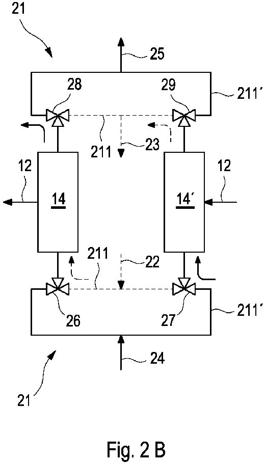
- the individual steps of the change are in 2A-C shown schematically, the illustration being largely reduced to the reactor devices 14, 14 'and the heat transfer circuits 211, 211' with the valve arrangement.
- the flow directions of the heat transfer medium are indicated by arrows.
- FIG. 2A shows the flow in the first half cycle.
- Warm heat transfer medium (solid arrows) flows from the second heat transfer circuit 211 '(solid line) into the reactor device 14 via the line means 21 and the valve means 26, 27 and cold heat transfer medium (dashed arrows) from the first heat transfer circuit 211 (dashed line) into the Reactor device 14 '.
- the heated or cooled flows of the heat transfer media are again fed to the corresponding heat transfer circuits 211, 211 'via the downstream valve means 28, 29.
- valve means 26, 27 upstream of the reactor devices 14, 14 ' are first switched after the half cycle (cf. Fig. 2 B) . Only after a switchover time are the valve means 28, 29 switched over downstream of the reactor devices 14 '.
- the resulting flow during the changeover time is in Figure 2B shown.
- the switching time corresponds to z. B. approximately the flow time of the heat transfer medium from the upstream valve means 26, 27 to the downstream valve means 28, 29.
- the switching time can be determined with knowledge of the mass or volume flow and the volume flow between the respective valve means.
- the changeover time can be several seconds, for example between 5s and 30s.
- FIG. 2C shows the flow in the second half cycle, after the change or switching process.
- the heated or cooled flows of the heat transfer media are fed back to the corresponding heat transfer circuits 211, 211 'via the downstream valve means 28, 29.
- the remaining volume of heat transfer medium which is located between the upstream valve means 26, 27 and the downstream valve means 28, 29, can flow out of the corresponding heat transfer circuit 211, 211 ' it has flowed into the reactor device 14, 14 '. Only after the outflow are the downstream valve means 28, 29 switched to the other heat transfer circuit 211 ', 211 (or vice versa). This prevents a residual volume flow of cold or warm heat transfer medium from entering the other heat transfer circuit 211 ', 211, i.e. flows in the warm or cold heat transfer circuit 211 ', 211 (or vice versa) and there causes an undesirable cooling or heating.
- the absorption or reaction gas uptake in the reaction material can be stopped, e.g. B. by interrupting the flow connection of the reaction gas to the reactor devices 14, 14 '.
- the reaction passage 13 can, if necessary, via a bypass section 122 (cf. Fig. 1 ) are supplied with reaction gas. It can thus be prevented that warm or cold heat transfer medium, which is already flowing in from a switched heat transfer circuit 211 ', 211, is undesirably subjected to cold or heat within the respective reactor device 14, 14'.
- thermoregulation arrangement 1 can be used extremely advantageously based on a thermochemical reaction. Investigations by the inventors have shown that the efficiency of the thermoregulation arrangement 1 is considerably increased by the asynchronous change.
Landscapes
- Engineering & Computer Science (AREA)
- Physics & Mathematics (AREA)
- Mechanical Engineering (AREA)
- Thermal Sciences (AREA)
- General Engineering & Computer Science (AREA)
- Life Sciences & Earth Sciences (AREA)
- Sustainable Development (AREA)
- Sustainable Energy (AREA)
- Chemical & Material Sciences (AREA)
- Combustion & Propulsion (AREA)
- Sorption Type Refrigeration Machines (AREA)
Abstract

Description
- Die Erfindung betrifft ein Verfahren zum Betreiben einer Thermoregulierungsanordnung zur Temperierung (thermischen Regulierung) eines mit der Thermoregulierungsanordnung in thermischem Kontakt stehenden Systems, das insbesondere innerhalb eines Fahrzeugs angeordnet ist, bei dem in einem Reaktionsgassystem Reaktionsgas von einer Reaktionsgasquelle unter Zwischenschaltung einer Temperieranordnung in eine Reaktionsgassenke geleitet wird, wobei in der in dem Reaktionsgassystem angeordneten Temperieranordnung in zumindest einer Reaktorvorrichtung mit Reaktionsmaterial in einem Absorptionsbetrieb Wärme und anschließend in einem Desorptionsbetrieb Kälte erzeugt wird oder umgekehrt, wobei in dem Absorptionsbetrieb Reaktionsgas von dem Reaktionsmaterial unter Wärmeabgabe absorbiert wird und in dem Desorptionsbetrieb Reaktionsgas von dem Reaktionsmaterial unter Wärmeaufnahme desorbiert wird, und wobei die zumindest eine Reaktorvorrichtung von einem Wärmeträgermedium zur Aufnahme der erzeugten Wärme oder Kälte durchströmt wird wobei im Desorptionsbetrieb ein erster Wärmeträgerkreislauf und im Absorptionsbetrieb ein zweiter Wärmeträgerkreislauf, mit einer anderen, vorzugsweise höheren, Austrittstemperatur des Wärmeträgermediums aus der Reaktorvorrichtung als in dem ersten Wärmeträgerkreislauf, mit der Reaktorvorrichtung in Strömungsverbindung steht. Die Erfindung betrifft ferner eine Thermoregulierungsanordnung und ein Fahrzeug mit derselben.
- Im Rahmen der Elektromobilität stellt die Fahrzeuginnenraumklimatisierung eine erhebliche Herausforderung dar. Zum einen wird durch den Einsatz konventionell elektrisch betriebener Klimaanlagen die Reichweite des Fahrzeugs um etwa 35 % bis 50 % reduziert. Zum anderen erfordern derartige Klimaanlagen den Einsatz unterschiedlicher und teilweise giftiger Kältemittel. Daher besteht Bedarf an alternativen Klimatisierungstechnologien, die gegebenenfalls auch in konventionellen Verbrennungsmotoren einsetzbar sind.
- Einen vielversprechenden Ansatz stellt die Verwendung thermochemischer Gas-Feststoff-Reaktionssysteme (kurz "Reaktionssysteme") dar, wobei ein Reaktionsgas in einer exothermen, d. h. Wärme freisetzenden Reaktion reversibel an einen Feststoff als Reaktionsmaterial gebunden wird (Absorption). In der endothermen Rückreaktion unter Freisetzung des Reaktionsgases (Desorption) und Wärmeaufnahme aus der Umgebung ist Kälte erzeugbar. Als Materialpaarungen des Reaktionssystems sind beispielsweise Wasserstoff als Reaktionsgas und ein Metall als Feststoff geeignet, wobei in beladenem Zustand ein Metallhydrid entsteht. Der Antrieb dieser Systeme erfolgt bei den sogenannten geschlossenen Systemen durch eine Wärmequelle und bei den sogenannten offenen Systemen durch eine Druckdifferenz in der Reaktionsgas-Versorgung.
- Ein Verfahren und eine Thermoregulierungsanordnung der eingangs genannten Art sind aus der
DE 10 2014 109 580 B3 bekannt. Hierbei wird ein geschlossenes System innerhalb der Thermoregulierungsanordnung verwendet. - In der Veröffentlichung "Linder M, Kulenovic R, An energy-efficient air-conditioning system for hydrogen driven cars, Int. J Hydrogen Energy 2011, 36: 3215-3221" ist ein Versuchsaufbau mit Untersuchungen zu einer Klimaanlage zur Kälteerzeugung zum Einsatz in einem offenen System angegeben.
- Der Erfindung liegt die Aufgabe zugrunde, ein effizienzerhöhendes Verfahren zum Betreiben einer Thermoregulierungsanordnung bereitzustellen, sowie eine entsprechend betreibbare Thermoregulierungsanordnung und ein Fahrzeug mit derselben.
- Die Aufgabe wird für das Verfahren mit den Merkmalen des Anspruchs 1 gelöst. Dabei ist vorgesehen, dass bei einem Wechsel von dem Absorptionsbetrieb auf den Desorptionsbetrieb oder umgekehrt die Strömungsverbindung der Reaktorvorrichtung mit dem zweiten Wärmeträgerkreislauf auf den ersten Wärmeträgerkreislauf umgeschaltet wird oder umgekehrt, wobei zunächst eine Strömungsverbindung stromauf der Reaktorvorrichtung auf den anderen Wärmeträgerkreislauf umgeschaltet wird und nach einer Umschaltzeit (einer Dauer des Umschaltevorgangs) die Strömungsverbindung stromab der Reaktorvorrichtung auf diesen anderen Wärmeträgerkreislauf umgeschaltet wird. Zur Steuerung dieses Verfahrens umfasst die Thermoregulierungsanordnung insbesondere eine entsprechend ausgebildete Steuereinrichtung.
- So erfolgen die Umschaltungen der Strömungsverbindungen stromauf und stromab der Reaktorvorrichtung nicht zeitgleich, sondern mit einem Zeitversatz entsprechend der Umschaltzeit. Eine derartige asynchrone Umschaltung bewirkt, dass noch in der Reaktorvorrichtung vorhandenes Restvolumen an Wärmeträgermedium in den unmittelbar vor dem Wechsel mit der Reaktorvorrichtung gekoppelten Wärmeträgerkreislauf abströmen kann. So wird verhindert, dass das Restvolumen in den anschließend an den Wechsel gekoppelten Wärmeträgerkreislauf strömt, welcher in der Regel einen anderen Temperaturbereich, zumindest eine andere Austrittstemperatur, aufweist. Ein Eintritt von Wärmeträgermedium in den jeweils anderen Wärmeträgerkreislauf, mit einem anderen Temperaturniveau, und ein damit verbundener unerwünschter Wärme- oder "Kälte"-verlust lässt sich auf diese Weise vermeiden. Zudem kann die zunächst in der Reaktormasse gespeicherte Wärme das Restvolumen an Wärmeträgermedium weiter wärmen bzw. kühlen, so das eine Art Wärmerückgewinnung stattfinden kann. Untersuchungen der Erfinder haben gezeigt, dass so die Effizienz des Systems und damit die erbrachte thermische Leistung vorteilhaft deutlich erhöht werden kann.
- In einer bevorzugten Ausführungsvariante des Verfahrens wird die Umschaltzeit in Abhängigkeit einer Durchströmzeit des Wärmeträgermediums durch zumindest die Reaktorvorrichtung ermittelt, wobei die Umschaltzeit vorzugsweise (zumindest im Wesentlichen, zum Beispiel unter Berücksichtigung von Toleranzzeiten) der Durchströmzeit entspricht. Besonders vorteilhaft wird die Umschaltzeit in Abhängigkeit einer Durchströmzeit des Wärmeträgermediums eines zu durchströmenden Volumens ausgehend von einer stromauf der Reaktorvorrichtung angeordneten Kopplungsstelle (z. B. gebildet durch ein erstes Ventilmittel) bis zu einer stromab angeordneten Kopplungsstelle (z. B. gebildet durch ein zweites Ventilmittel) der Reaktorvorrichtung zur Strömungsverbindung mit dem Wärmeträgerkreislauf ermittelt. Dementsprechend kann, je nach Volumen der Reaktorvorrichtung (seitens des Wärmeträgermediums) und/oder gegebenenfalls dem Gesamtvolumen zwischen den Kopplungsstellen, und Durchflussgeschwindigkeit des Wärmeträgermediums, die Umschaltzeit bestimmt und in eine Steuerung durch eine Steuereinrichtung der Thermoregulierungsanordnung implementiert werden. Auf diese Weise kann mit guter Genauigkeit sichergestellt werden, dass das Restvolumen dem entsprechend temperierten Wärmeträgerkreislauf zugeführt wird, was der Effizienz des Verfahrens zuträglich ist.
- Insbesondere bei einem offenen System, das zyklisch betrieben wird, ist es vorteilhaft, wenn während der Umschaltzeit die Strömung des Reaktionsgases durch die Reaktorvorrichtung unterbrochen wird, z. B. durch Unterbrechung der Strömungsverbindung von Reaktionsgas zu der Reaktorvorrichtung (oder von der Reaktorvorrichtung). Auf diese Weise kann die Absorption (oder die Desorption) des Reaktionsgases unterbrochen werden. So wird verhindert, dass das warme bzw. kalte Restvolumen unerwünschter Weise mit dann erzeugter Kälte bzw. Wärme beaufschlagt wird.
- In einer bevorzugten Ausführungsvariante werden bei dem Wechsel in den Wärmeträgerkreisläufen vorhandene Ventilmittel zumindest teilweise mit der Umschaltzeit versetzt zueinander umgeschaltet, wobei zunächst ein erstes Ventilmittel stromauf der Reaktorvorrichtungen umgeschaltet wird und nach der Umschaltzeit ein zweites Ventilmittel stromab der Reaktorvorrichtungen umgeschaltet wird. Die Ventilmittel, insbesondere Wegeventile, erlauben ein einfach steuerbares bzw. regelbares Umschalten der Strömungsverbindung.
- Vorzugsweise wird der Wechsel zwischen dem Absorptionsbetrieb und dem Desorptionsbetrieb in Abhängigkeit von Betriebsgrößen, insbesondere eines (Betriebs-) Drucks und/oder einer Temperatur eingeleitet (gesteuert und/oder geregelt), wobei ein anderer Betriebsdruck an die Reaktorvorrichtung angelegt wird. Die Temperatur kann zum Beispiel eine Temperaturdifferenz über eine bestimmte Zeitspanne in dem Wärmeträgermedium oder in dem Reaktionsmaterial sein. Die Einstellung erfolgt vorzugsweise mittels einer Steuereinrichtung der Thermoregulierungsanordnung, die auch einem (übergeordneten) Steuergerät zugeordnet sein kann. Der Betriebsdruck der Reaktorvorrichtung entspricht einem über das Reaktionsgassystem angelegten Druck. Durch die erzeugte Druckdifferenz an der Reaktorvorrichtung ergibt sich die Triebkraft des Absorptionsbetriebs bzw. Desorptionsbetriebs. So ist die Thermoregulierungsanordnung präzise steuerbar bzw. regelbar.
- Vorzugsweise wird der jeweilige Betriebsdruck in der (bzw. angelegt an die) Reaktorvorrichtung und/oder die Reaktionsgas-Massenströme zu bzw. von der Reaktorvorrichtung in Abhängigkeit von Randbedingungen (insbesondere einer erforderlichen Temperatur des Wärmeträgermediums entsprechend dessen Verwendungszweck, beispielsweise zur Klimatisierung) und/oder einer erforderlichen thermischen Leistung eingestellt. Die Betriebsdrücke liegen insbesondere zwischen einem durch die Reaktionsgasquelle, beispielsweise einer Speichereinrichtung, bereitgestellten Druck und einem durch die Reaktionsgassenke, beispielsweise eine Energiewandeleinrichtung, bereitgestellten Druck. Zur Einstellung ist vorzugsweise, neben der Steuereinrichtung, eine entsprechende Einrichtung in Leitungsmitteln des Reaktionsgassystems vorhanden. Auf diese Weise wird ein Verfahren bereitgestellt, mittels dessen flexibel auf unterschiedliche Umgebungsbedingungen reagiert werden kann.
- In einer besonders effizienten Betriebsweise sind zumindest zwei Reaktorvorrichtungen vorhanden, die zyklisch zueinander versetzt wechselweise im Absorptionsbetrieb und im Desorptionsbetrieb betrieben werden. Auf diese Weise kann kontinuierlich Kälte bzw. Wärme bereitgestellt werden, die einmal von der einen und, nach dem Wechsel, anschließend von der anderen Reaktorvorrichtung abgenommen wird.
- Dabei wird in einem Halbzyklus eine der Reaktorvorrichtungen im Absorptionsbetrieb betrieben, wobei Reaktionsgas aus der Reaktionsgasquelle (z. B. der Speichereinrichtung) zur Absorption in die jeweilige Reaktorvorrichtung geleitet wird und die abgegebene Wärme von dem Wärmeträgermedium aufgenommen wird. Die jeweils andere Reaktorvorrichtung wird im Desorptionsbetrieb betrieben, wobei Reaktionsgas aus der Reaktorvorrichtung in die Reaktionsgassenke (beispielsweise eine Energiewandeleinrichtung) geleitet wird, wobei Wärme aus dem Wärmeträgermedium aufgenommen und so das Wärmeträgermedium abgekühlt wird. Nach einer Halbzykluszeit werden zum Wechsel die Strömungsverbindungen des Reaktionsgases und/oder des Wärmeträgermediums umgeschaltet und anschließend in dem anderen Halbzyklus die jeweils anderen Reaktorvorrichtungen im Absorptionsbetrieb und im Desorptionsbetrieb betrieben. Die Halbzykluszeit ist abhängig von der Auslegung der Thermoregulierungsanordnung und den Betriebsparametern und kann z. B. 30 s bis 300 s, beispielsweise 60 s bis 180 s betragen. Bei einer derartigen Betriebsweise, die eine kontinuierliche Wärme- bzw. Kältebereitstellung ermöglicht, trägt das erfindungsgemäße Verfahren aufgrund der vergleichsweise häufigen Wechsel besonders zur Effizienzsteigerung bei.
- Die Aufgabe bezüglich der Thermoregulierungsanordnung wird mit den Merkmalen des Anspruchs 9 gelöst. Vorteilhafte Ausgestaltungen sind sinngemäß in Zusammenhang mit den vorstehend beschriebenen Ausführungsvarianten des Verfahrens angegeben.
- In einer vorteilhaften Ausgestaltungsvariante der Thermoregulierungsanordnung umfasst das Reaktionsmaterial einen Feststoff aufweisend ein Metallhydrid, insbesondere eine Titan-Mangan-Legierung und/oder ist das Reaktionsgas durch Wasserstoff gebildet. Durch Wasserstoff als Reaktionsgas kann eine hohe Leistungsdichte und eine schnelle Reaktionszeit erreicht werden. Für die Anwendung einer Fahrzeugklimatisierung vorteilhafte Temperaturniveaus ergeben sich durch die Verwendung einer Titan-Mangan-Legierung in Kombination mit Wasserstoff.
- Die Aufgabe bezüglich des Fahrzeuges wird mit den Merkmalen des Anspruchs 11 gelöst. Das Fahrzeug umfasst neben der Thermoregulierungsanordnung zumindest ein damit in thermischem Kontakt stehendes zu temperierendes System. Dies kann ein Wärmetauscher zur Klimatisierung eines Fahrzeuginnenraums und/oder eines anderen (Kühl-) Raums des Fahrzeugs sein und/oder Leistungselektronik, eine Komponente des Antriebssystems und/oder ein anderes zu temperierendes bzw. thermisch zu regulierendes System innerhalb des Fahrzeugs.
- Nachfolgend wird die Erfindung anhand von Ausführungsbeispielen unter Bezugnahme auf die Zeichnungen näher erläutert. Es zeigen:
- Fig. 1
- ein Fließschema einer beispielhaften Thermoregulierungsanordnung, die zum Betrieb mit dem erfindungsgemäßen Verfahren ausgebildet ist, mit zwei Reaktorvorrichtungen, und
- Fig. 2A-C
- Fließschemata mit zwei Reaktorvorrichtungen zur schematischen Veranschaulichung eines Wechsels.
-
Fig. 1 zeigt ein Fließschema einer Thermoregulierungsanordnung 1 zur Temperaturregulierung eines oder mehrerer damit in thermischem Kontakt stehender Systeme (hier nicht gezeigt). Die Thermoregulierungsanordnung 1 und die Systeme können beispielsweise innerhalb eines Fahrzeugs angeordnet sein. Bei den Systemen kann es sich z.B. um einen Fahrzeuginnenraum, um Leistungselektronik eines Fahrzeuges, Energieerzeugungsaggregate wie eine Brennstoffzelle und/oder einen Verbrennungsmotor und/oder eine Energiespeicheranordnung wie beispielsweise eine Batterieanordnung handeln. Die Systeme können als Wärmequelle und/oder als Wärmesenke dienen, was sich je nach System in Abhängigkeit von Randbedingungen, z. B. von der Umgebungstemperatur, ändern kann. Bei einem reinen Kältebetrieb der Thermoregulierungsanordnung, zur Abkühlung eines Systems, kann die Umgebung als Wärmesenke dienen. - Das Fahrzeug kann insbesondere einen Brennstoffzellenantrieb aufweisen, als alleiniges Antriebsaggregat oder in Kombination mit z. B. einem Elektro- und/oder Verbrennungsmotor als Hybridvariante. Das Fahrzeug umfasst ein Reaktionsgassystem 10 mit einer Reaktionsgasquelle 11 für Reaktionsgas, insbesondere Wasserstoff, und eine Reaktionsgassenke 13. Die Reaktionsgasquelle 11 kann insbesondere von einer Speichereinrichtung gebildet sein. Die Reaktionsgassenke 13 kann insbesondere von einer mit Reaktionsgas betriebenen Energiewandeleinrichtung gebildet sein. Die Reaktionsgassenke 13 steht mittelbar oder unmittelbar (d.h. gegebenenfalls unter Zwischenschaltung zumindest einer Reaktorvorrichtung 14, 14'), über Leitungsmittel 12 mit der Reaktionsgasquelle 11 in Strömungsverbindung und wird aus der Reaktionsgasquelle 11 mit Reaktionsgas versorgt. In der Reaktionsgassenke 13 wird die in dem Reaktionsgas gespeicherte Energie in eine andere Energieform umgesetzt. Bei der Reaktionsgassenke 13 kann es sich insbesondere um eine Brennstoffzelle handeln.
- Die Thermoregulierungsanordnung 1 umfasst vorzugsweise Teile der in dem Fahrzeug vorhandenen (Antriebs-)Peripherie, insbesondere das Reaktionsgassystem 10 mit der Reaktionsgasquelle 11 und der Reaktionsgassenke 13. In das Reaktionsgassystem 10 ist strömungsmechanisch eine Temperieranordnung 30 der Thermoregulierungsanordnung 1 eingebunden, die basierend auf dem Prinzip der thermochemischen Reaktion (bzw. Sorption), insbesondere Absorption und Desorption, Wärme und/oder Kälte erzeugen kann. Zur Wärmeabgabe bzw. Wärmefreisetzung wird dabei das Reaktionsgas in einer exothermen Reaktion reversibel an das Reaktionsmaterial als Speichermaterial gebunden (Absorption). Zur Wärmeaufnahme bzw. "Kältefreisetzung" wird das Reaktionsgas in der endothermen Rückreaktion aus dem Reaktionsmaterial freigesetzt (Desorption). Der Beladungszustand des Feststoffes ist an ein bestimmtes Temperatur- und Druckniveau gekoppelt, welches sich im Gleichgewicht einstellt. Dieses wiederum ist abhängig von dem jeweiligen Reaktionssystem, d. h. dem verwendeten Reaktionsgas und Feststoff bzw. Reaktionsmaterial.
- Die Temperieranordnung 30 weist beispielhaft zwei Reaktorvorrichtungen 14, 14' auf, die jeweils mit Reaktionsmaterial gefüllt sind. Das Reaktionsmaterial ist vorzugsweise durch einen Feststoff gebildet und umfasst bevorzugt Metallhydrid. Das Reaktionsmaterial, insbesondere Metallhydrid, und das Reaktionsgas, insbesondere Wasserstoff, bilden komplementäre Bestandteile des thermochemischen Reaktions-, insbesondere Sorptionssystems. Die Verwendung von Wasserstoff als Reaktionsgas bietet den Vorteil einer hohen Leistungsdichte. Als Feststoffe sind, insbesondere in Verbindung mit Wasserstoff, Titan-Mangan-Legierungen für die Anwendung in der Thermoregulierungsanordnung 1 besonders geeignet, insbesondere aufgrund der für den Anwendungsfall geeigneten Druck-Temperatur-Korrelationen bei Absorption und Desorption.
- Die Temperieranordnung 30 mit den Reaktorvorrichtungen 14, 14' ist innerhalb der Leitungsmittel 12 zwischen der Reaktionsgasquelle 11 und der Reaktionsgassenke 13 angeordnet. In den Leitungsmitteln 12 ist eine Ventilanordnung vorhanden, mittels derer die Strömungswege des Reaktionsgases über die Leitungsmittel 12 steuerbar sind. Insbesondere können die Reaktorvorrichtungen 14, 14' einzeln oder gleichzeitig mit dem Reaktionsgas aus der Reaktionsgasquelle 11 versorgt werden. Weiterhin kann aus einer oder beiden Reaktorvorrichtungen 14, 14' Reaktionsgas über die Leitungsmittel 12 der Reaktionsgassenke 13 zugeführt werden.
- Dabei sind hier beispielhaft die Leitungsmittel 12 ausgehend von der Reaktionsgasquelle 11 zunächst als ein einziger Leitungsstrang ausgebildet. Dieser Leitungsstrang teilt sich in zwei parallele Teilleitungsstränge 121, 121' zur Versorgung der jeweiligen Reaktorvorrichtungen 14, 14' auf. Für eine Umschaltbarkeit der Strömungswege bzw. Strömungsverbindungen sind in den Teilleitungssträngen 121, 121' jeweils Ventilmittel 17, 17' der Ventilanordnung, z. B. 3/2-Wegeventile, angeordnet, über die die Teilleitungsstränge 121, 121' jeweils mit den Reaktorvorrichtungen 14, 14' verbunden werden können. Je nach Ventilstellung kann dabei eine Strömungsverbindung der jeweiligen Reaktorvorrichtung 14, 14' zu der Reaktionsgasquelle 11 oder zu der Reaktionsgassenke 13 hergestellt werden.
- Parallel zu den Teilleitungssträngen 121, 121' ist ein Bypassabschnitt 122 der Leitungsmittel 12 mit einem Bypassventilmittel 18 der Ventilanordnung vorhanden. Über den Bypassabschnitt 122 kann das Reaktionsgas unmittelbar, d.h. ohne Zwischenschaltung der Reaktorvorrichtungen 14, 14', von der Reaktionsgasquelle 11 zu der Reaktionsgassenke 13 strömen. So kann Reaktionsgas zusätzlich oder ausschließlich über den Bypassabschnitt 122 zu der Reaktionsgassenke 13 geführt werden. Dies kann beispielsweise bei einem hohen Reaktionsgasbedarf der Reaktionsgassenke 13, beispielsweise bei einem hohen Leistungsbedarf des Fahrzeuges, vorteilhaft sein, oder in einem Betriebsmodus der Temperieranordnung 30, wobei der Reaktionsgassenke 13 kein Reaktionsgas aus den Reaktorvorrichtungen 14, 14' zugeführt wird.
- In vollständig gefülltem Zustand weist die Reaktionsgasquelle 11 vorzugsweise einen hohen Druck von z. B. mehr als 100 bar auf, um eine hohe Masse an Reaktionsgas aufnehmen zu können. Die Reaktionsgassenke 13 hingegen weist einen bedeutend niedrigeren Arbeitsdruck, beispielsweise zwischen 5 bar und 40 bar, auf. Gemäß einem Kerngedanken der Erfindung ist der Aufbau der Thermoregulierungsanordnung 1 derart, dass dieses Druckgefälle als Triebkraft für die Temperieranordnung 30 genutzt wird.
- Zu diesem Zweck ist stromab der Reaktionsgasquelle 11 und stromauf der Reaktorvorrichtung/en 14, 14' bzw. der Reaktormaterialien zumindest ein erstes Druck- und/oder Durchflussregulierungsmittel angeordnet. Weiterhin ist stromauf der Reaktionsgassenke 13 und stromab der Reaktorvorrichtung/en 14, 14' zumindest ein zweites Druck- und/oder Durchflussregulierungsmittel angeordnet. Die Druck- und/oder Durchflussregulierungsmittel können beispielsweise, wie in
Fig. 1 gezeigt, in den Leitungssträngen stromauf und stromab der Teilleitungsstränge 121, 121', hier in Form eines ersten und eines zweiten Druck-Ventilmittels 15, 15', vorhanden sein. Auf diese Weise lässt sich der Druck aus der Reaktionsgasquelle 11 auf einen jeweiligen Betriebsdruck für die Reaktorvorrichtungen 14, 14' reduzieren. Der Betriebsdruck liegt somit zwischen dem Druck in der Reaktionsgasquelle 11 und dem Arbeitsdruck in der Reaktionsgassenke 13. - Für eine präzise Steuerbarkeit bzw. Regelbarkeit eines Wechsels zwischen Absorptions- und Desorptionsbetrieb sind den Reaktorvorrichtungen 14, 14' vorzugsweise jeweils zumindest ein Sensorelement 16, 16' zur Ermittlung des Betriebsdrucks und/oder einer (Betriebs-)Temperatur zugeordnet. In
Fig. 1 sind die Sensorelemente 16, 16' beispielhaft jeweils den Reaktorvorrichtungen 14, 14' zugeordnet, wobei sie stromab derselben in den jeweiligen Teilleitungssträngen 121, 121' angeordnet sind. Möglich wäre auch eine Anordnung an anderer Stelle, beispielsweise innerhalb der Reaktorvorrichtungen 14, 14'. - Zur thermischen Kopplung der Temperieranordnung mit den zu temperierenden Systemen umfasst die Thermoregulierungsanordnung 1 ein Wärmetransportsystem 20. Das Wärmetransportsystem weist Leitungsmittel 21 zur Leitung eines Wärmeträgermediums auf. Das Wärmeträgermedium kann beispielsweise eine Flüssigkeit und/oder ein Gas sein.
- Das Wärmetransportsystem 20 weist einen ersten Wärmeträgerkreislauf 211 mit einem ersten Eintritt 22 und einem ersten Austritt 23 auf, um eine Strömungsverbindung zu einer Wärmequelle, insbesondere einem zu kühlenden System, herzustellen. Weiterhin weist das Wärmetransportsystem einen zweiten Wärmeträgerkreislauf 211' mit einem zweiten Eintritt 24 und einem zweiten Austritt 25 auf, um eine Strömungsverbindung zu einer Wärmesenke, insbesondere einem zu beheizenden System oder der Umgebung, herzustellen.
- Durch eine entsprechend ausgebildete Ventilanordnung des Wärmetransportsystems kann der erste Wärmeträgerkreislauf 211 wechselweise mit der Reaktorvorrichtung 14 und der Reaktorvorrichtung 14' und gleichzeitig der zweite Wärmeträgerkreislauf 211' mit der jeweils anderen Reaktorvorrichtung 14', 14 zur Wärmeübertragung von dem bzw. in das Reaktionsmaterial in Strömungsverbindung gebracht werden. Der Wechsel der Teilkreisläufe 211, 211' auf die jeweils andere Reaktorvorrichtung 14, 14' erfolgt in einem Wechsel.
- Dazu weist die Ventilanordnung des Wärmetransportsystems beispielhaft stromauf der Reaktorvorrichtungen 14, 14' zwei Ventilmittel 26 und 27 auf, die vorzugsweise als Wegeventile, insbesondere 3/2-Wegeventile, ausgebildet sind. An die Ventilmittel 26, 27 sind jeweils die Zuläufe der ersten und der zweiten Teilkreisläufe 211, 211' sowie die Reaktorvorrichtung 14 (an das Ventilmittel 26) bzw. die Reaktorvorrichtung 14' (an das Ventilmittel 27) angeschlossen bzw. gekoppelt. Stromab der Reaktorvorrichtungen 14, 14' sind zwei Ventilmittel 28, 29 vorhanden, an die die Reaktorvorrichtung 14 (an das Ventilmittel 28) bzw. die Reaktorvorrichtung 14' (an das Ventilmittel 29) angeschlossen bzw. gekoppelt sind, sowie jeweils der erste und der zweite Wärmeträgerkreislauf 211, 211'.
- Die Thermoregulierungsanordnung 1 wird zyklisch betrieben, wobei kontinuierlich sowohl Kälte als auch Wärme erzeugt werden. Wird lediglich die erzeugte Kälte (z. B. in einer Klimatisierungsanordnung) oder die erzeugte Wärme genutzt, kann die jeweils nicht genutzte Wärme bzw. Kälte zur Regeneration der Reaktorvorrichtung 14, 14' an die Umgebung abgeführt bzw. Wärme aus der Umgebung aufgenommen werden. In einem Halbzyklus wird Reaktionsgas aus der Reaktionsgasquelle 11 in eine der Reaktorvorrichtungen 14 oder 14' geleitet und dort unter Wärmefreisetzung absorbiert. In der jeweils anderen Reaktorvorrichtung 14' oder 14 wird zeitgleich Reaktionsgas unter Wärmeaufnahme aus dem Wärmeträgermedium desorbiert. Das Reaktionsgas wird über die Leitungsmittel 12 der Reaktionsgassenke 13 zugeführt, wo es z. B. energetisch umgesetzt wird. Nach einer Halbzykluszeit von beispielsweise zwischen 30s und 300s, vorzugsweise zwischen 60s und 180s, werden die Reaktorvorrichtungen 14, 14' in einem Wechsel durch entsprechende Umschaltung der Ventilanordnungen in dem Reaktionsgassystem 10 und in dem Wärmetransportsystem 20 umgeschaltet. Nun wird der jeweils anderen Reaktorvorrichtung 14' oder 14 Reaktionsgas aus der Reaktionsgasquelle 11 zugeführt und aus der anderen Reaktorvorrichtung 14 oder 14' Reaktionsgas an die Reaktionsgassenke 13 abgegeben.
- Der Wechsel kann beispielsweise in Abhängigkeit von Signalen der vorhandenen Sensorelemente 16, 16' durch eine (hier nicht gezeigte) Steuereinrichtung eingeleitet werden, beispielsweise wenn ein bestimmtes Druck- und/oder Temperaturniveau erreicht ist. Beispielsweise kann der Wechsel eingeleitet werden, sobald der Druck an dem Sensorelement 16 bzw. 16' (je nachdem, welche der Reaktorvorrichtungen 14, 14' mit der Reaktionsgassenke 13 in Strömungsverbindung steht) den Arbeitsdruck bzw. den Versorgungsdruck der Reaktionsgassenke 13 erreicht (oder unterschreitet). Beispielsweise kann die Umschaltung auch eingeleitet werden, wenn ein in der Steuereinrichtung vorgegebener Temperaturhub oder eine Zieltemperatur innerhalb des Wärmeträgermediums nicht mehr erreicht wird.
- Vorliegend bildet beispielhaft der erste Wärmeträgerkreislauf 211 einen Kältekreislauf, der an ein oder mehrere zu kühlende/s System/e bzw. Wärmequelle/n (hier nicht gezeigt) angeschlossen ist. Zur "kontinuierlichen Kälteerzeugung" im kontinuierlichen Betrieb wird die Ventilanordnung des Wärmetransportsystems so eingestellt, dass das Wärmeträgermedium über den ersten Eintritt 22 und über das Ventilmittel 26 oder 27 jeweils in die desorbierende, d. h. Wärme aufnehmende, Reaktorvorrichtung 14 oder 14' geleitet wird. Dort gibt das Wärmeträgermedium Wärme an das Reaktionsmaterial ab und wird so gekühlt. Stromab der Reaktorvorrichtung 14 oder 14' wird das Wärmeträgermedium über das Ventilmittel 28 oder 29 dem ersten Austritt 23 zugeführt.
- Der zweite Wärmeträgerkreislauf 211' bildet beispielhaft einen Wärmekreislauf, der an ein oder mehrere zu erwärmende/s System/e oder die Umgebung als Wärmesenke/n (hier nicht gezeigt) angeschlossen ist. Zur "kontinuierlichen Wärmeerzeugung" im kontinuierlichen Betrieb wird die Ventilanordnung des Wärmetransportsystems so eingestellt, dass das Wärmeträgermedium über den zweiten Eintritt 24 und über das Ventilmittel 27 oder 26 jeweils an die absorbierende, d.h. wärmeabgebende, Reaktorvorrichtung 14' oder 14 geleitet wird. Dort nimmt das Wärmeträgermedium Wärme aus dem Reaktormaterial auf und wird so erwärmt. Stromab der Reaktorvorrichtung 14' oder 14 wird das Wärmeträgermedium über das Ventilmittel 29 oder 28 dem zweiten Austritt 25 zugeführt.
- Zur Steigerung der Effizienz der Thermoregulierungsanordnung 1 werden die Ventilmittel 26, 27 bei dem Wechsel asynchron zu den Ventilmitteln 28, 29 geschaltet. Die einzelnen Schritte des Wechsels sind in
Fig. 2A-C schematisch gezeigt, wobei die Darstellung vereinfachend weitgehend auf die Reaktorvorrichtungen 14, 14' und die Wärmeträgerkreisläufe 211, 211' mit der Ventilanordnung reduziert ist. Die Strömungsrichtungen des Wärmeträgermediums sind durch Pfeile angedeutet. -
Fig. 2A zeigt den Strömungsverlauf in dem ersten Halbzyklus. Dabei strömt über die Leitungsmittel 21 und die Ventilmittel 26, 27 warmes Wärmeträgermedium (durchgezogene Pfeile) aus dem zweiten Wärmeträgerkreislauf 211' (durchgezogene Linie) in die Reaktorvorrichtung 14 und kaltes Wärmeträgermedium (gestrichelte Pfeile) aus dem ersten Wärmeträgerkreislauf 211 (gestrichelte Linie) in die Reaktorvorrichtung 14' ein. Über die stromab angeordneten Ventilmittel 28, 29 werden die erwärmten bzw. abgekühlten Ströme der Wärmeträgermedien wieder den entsprechenden Wärmeträgerkreisläufen 211, 211' zugeleitet. - Bei dem Wechsel werden nach dem Halbzyklus zunächst die Ventilmittel 26, 27 stromauf der Reaktorvorrichtungen 14, 14' umgeschaltet (vgl.
Fig. 2 B) . Erst nach einer Umschaltzeit werden die Ventilmittel 28, 29 stromab der Reaktorvorrichtungen 14' umgeschaltet. Die sich dadurch ergebende Strömungsführung während der Umschaltzeit (d. h. während des Wechsels) ist inFig. 2B dargestellt. Die Umschaltzeit entspricht z. B. in etwa der Durchströmzeit des Wärmeträgermediums von den stromauf angeordneten Ventilmitteln 26, 27 zu den stromab angeordneten Ventilmitteln 28, 29. So ist die Umschaltzeit unter Kenntnis des Massen- bzw. Volumenstroms und des durchströmten Volumens zwischen den jeweiligen Ventilmitteln ermittelbar. Die Umschaltzeit kann, je nach System und Volumenstrom des Wärmeträgermediums, mehrere Sekunden, beispielsweise zwischen 5s und 30s betragen. -
Fig. 2C zeigt den Strömungsverlauf in dem zweiten Halbzyklus, nach dem Wechsel bzw. Umschaltvorgang. Nun strömt über die Leitungsmittel 21 und die Ventilmittel 26, 27 warmes Wärmeträgermedium (durchgezogene Pfeile) aus dem zweiten Wärmeträgerkreislauf 211' (durchgezogene Linie) in die Reaktorvorrichtung 14' und kaltes Wärmeträgermedium (gestrichelte Pfeile) aus dem ersten Wärmeträgerkreislauf 211 (gestrichelte Linie) in die Reaktorvorrichtung 14 ein. Über die stromab angeordneten Ventilmittel 28, 29 werden die erwärmten bzw. abgekühlten Ströme der Wärmeträgermedien wieder den entsprechenden Wärmeträgerkreisläufen 211, 211' zugeleitet. - Durch die asynchrone Ventilschaltung während des Wechsels zwischen den Halbzyklen kann jeweils das restliche Volumen an Wärmeträgermedium, welches sich zwischen den stromauf angeordneten Ventilmitteln 26, 27 und den stromab angeordneten Ventilmittel 28, 29 befindet, in den entsprechenden Wärmeträgerkreislauf 211, 211' abströmen, aus dem es in die Reaktorvorrichtung 14, 14' eingeströmt ist. Erst nach dem Abströmen werden auch die stromab angeordneten Ventilmittel 28, 29 auf den anderen Wärmeträgerkreislauf 211', 211 (oder umgekehrt) umgeschaltet. Dadurch wird verhindert, dass ein Restvolumenstrom an kaltem bzw. warmem Wärmeträgermedium in jeweils den anderen Wärmeträgerkreislauf 211', 211, d.h. den warmen bzw. kalten Wärmeträgerkreislauf 211', 211 (oder umgekehrt) einströmt und dort eine unerwünschte Abkühlung bzw. Erwärmung bewirkt.
- Während der Umschaltzeit kann die Absorption bzw. Reaktionsgasaufnahme in dem Reaktionsmaterial gestoppt werden, z. B. durch Unterbrechung der Strömungsverbindung des Reaktionsgases zu den Reaktorvorrichtungen 14, 14'. Die Reaktionsgassenke 13 kann, falls erforderlich, dabei über einen Bypassabschnitt 122 (vgl.
Fig. 1 ) mit Reaktionsgas versorgt werden. Somit kann verhindert werden, dass warmes bzw. kaltes Wärmeträgermedium, welches bereits aus einem umgeschalteten Wärmeträgerkreislauf 211', 211 nachströmt, unerwünschter Weise mit Kälte bzw. Wärme innerhalb der jeweiligen Reaktorvorrichtung 14, 14' beaufschlagt wird. - Das Prinzip des asynchronen Wechsels, z. B. durch die asynchrone Ventilschaltung, wie anhand der
Fig. 2A-C beschrieben, kann auch bei anderen Systemkonfigurationen als bei der inFig. 1 gezeigten Thermoregulierungsanordnung 1 basierend auf einer thermochemischen Reaktion äußerst vorteilhaft angewandt werden. Untersuchungen der Erfinder haben gezeigt, dass durch den asynchronen Wechsel die Effizienz der Thermoregulierungsanordnung 1 erheblich gesteigert wird.
Claims (11)
- Verfahren zum Betreiben einer Thermoregulierungsanordnung (1) zur Temperierung eines mit der Thermoregulierungsanordnung (1) in thermischem Kontakt stehenden Systems, das insbesondere innerhalb eines Fahrzeugs angeordnet ist,
bei dem in einem Reaktionsgassystem (10) Reaktionsgas von einer Reaktionsgasquelle (11) unter Zwischenschaltung einer Temperieranordnung (30) in eine Reaktionsgassenke (13) geleitet wird,
wobei in der in dem Reaktionsgassystem (10) angeordneten Temperieranordnung (30) in zumindest einer Reaktorvorrichtung (14, 14') mit Reaktionsmaterial in einem Absorptionsbetrieb Wärme und anschließend in einem Desorptionsbetrieb Kälte erzeugt wird oder umgekehrt, wobei in dem Absorptionsbetrieb Reaktionsgas von dem Reaktionsmaterial unter Wärmeabgabe absorbiert wird und in dem Desorptionsbetrieb Reaktionsgas von dem Reaktionsmaterial unter Wärmeaufnahme desorbiert wird, und
wobei die zumindest eine Reaktorvorrichtung (14, 14') von einem Wärmeträgermedium zur Aufnahme der erzeugten Wärme oder Kälte durchströmt wird, wobei im Desorptionsbetrieb ein erster Wärmeträgerkreislauf (211) und im Absorptionsbetrieb ein zweiter Wärmeträgerkreislauf (211'), mit einer anderen, vorzugsweise höheren, Austrittstemperatur des Wärmeträgermediums aus der Reaktorvorrichtung (14, 14') als in dem ersten Wärmeträgerkreislauf (211), mit der Reaktorvorrichtung (14, 14') in Strömungsverbindung steht,
dadurch gekennzeichnet,
dass bei einem Wechsel von dem Absorptionsbetrieb auf den Desorptionsbetrieb oder umgekehrt die Strömungsverbindung der Reaktorvorrichtung (14, 14') mit dem zweiten Wärmeträgerkreislauf (211') auf den ersten Wärmeträgerkreislauf (211) umgeschaltet wird oder umgekehrt, wobei zunächst eine Strömungsverbindung stromauf der Reaktorvorrichtung (14, 14') auf den anderen Wärmeträgerkreislauf (211, 211') umgeschaltet wird und nach einer Umschaltzeit die Strömungsverbindung stromab der Reaktorvorrichtung (14, 14') auf diesen anderen Wärmeträgerkreislauf (211, 211') umgeschaltet wird. - Verfahren nach Anspruch 1,
dadurch gekennzeichnet,
dass die Umschaltzeit in Abhängigkeit einer Durchströmzeit des Wärmeträgermediums durch zumindest die Reaktorvorrichtung (14, 14') ermittelt wird, wobei die Umschaltzeit vorzugsweise der Durchströmzeit entspricht. - Verfahren nach Anspruch 1 oder 2,
dadurch gekennzeichnet,
dass während der Umschaltzeit die Strömung des Reaktionsgases durch die Reaktorvorrichtung (14, 14') unterbrochen wird. - Verfahren nach einem der vorhergehenden Ansprüche,
dadurch gekennzeichnet,
dass bei dem Wechsel in den Wärmeträgerkreisläufen (211, 211') vorhandene Ventilmittel (26, 27, 28, 29) zumindest teilweise mit der Umschaltzeit versetzt zueinander umgeschaltet werden, wobei zunächst ein erstes Ventilmittel (26, 27) stromauf der Reaktorvorrichtung (14, 14') umgeschaltet wird und nach der Umschaltzeit ein zweites Ventilmittel (28, 29) stromab der Reaktorvorrichtung (14, 14') umgeschaltet wird. - Verfahren nach einem der vorhergehenden Ansprüche,
dadurch gekennzeichnet,
dass der Wechsel zwischen dem Absorptionsbetrieb und dem Desorptionsbetrieb in Abhängigkeit von Betriebsgrößen, insbesondere eines Drucks und/oder einer Temperatur, eingeleitet wird, wobei ein anderer Betriebsdruck an die Reaktorvorrichtung (14, 14') angelegt wird. - Verfahren nach einem der vorhergehenden Ansprüche,
dadurch gekennzeichnet,
dass ein jeweiliger Betriebsdruck in der Reaktorvorrichtung (14, 14') und/oder die Reaktionsgas-Massenströme zu bzw. von der Reaktorvorrichtung (14, 14') in Abhängigkeit von Randbedingungen, insbesondere einer erforderlichen Temperatur des Wärmeträgermediums und/oder einer erforderlichen thermischen Leistung, eingestellt wird. - Verfahren nach einem der vorhergehenden Ansprüche,
dadurch gekennzeichnet,
dass zumindest zwei Reaktorvorrichtungen (14, 14') vorhanden sind, die zyklisch zueinander versetzt wechselweise im Absorptionsbetrieb und im Desorptionsbetrieb betrieben werden. - Verfahren nach Anspruch 7,
dadurch gekennzeichnet,
dass in einem Halbzyklus eine der Reaktorvorrichtungen (14, 14') im Absorptionsbetrieb betrieben wird, wobei Reaktionsgas aus der Reaktionsgasquelle (11) zur Absorption in die jeweilige Reaktorvorrichtung (14, 14') geleitet wird und die abgegebene Wärme von dem Wärmeträgermedium aufgenommen wird, und die jeweils andere Reaktorvorrichtung (14', 14) im Desorptionsbetrieb betrieben wird, wobei Reaktionsgas aus der Reaktorvorrichtung (14', 14) in die Reaktionsgassenke (13) geleitet wird, wobei Wärme aus dem Wärmeträgermedium aufgenommen und so das Wärmeträgermedium abgekühlt wird,
und dass nach einer Halbzykluszeit in dem Wechsel die Strömungsverbindungen des Reaktionsgases und des Wärmeträgermediums umgeschaltet werden und anschließend in dem anderen Halbzyklus die jeweils anderen Reaktorvorrichtungen (14', 14) im Absorptionsbetrieb und im Desorptionsbetrieb betrieben werden. - Thermoregulierungsanordnung (1) zur Temperierung eines damit in thermischem Kontakt stehenden Systems, insbesondere innerhalb eines Fahrzeugs, das dazu ausgebildet ist, ein Verfahren nach einem der vorhergehenden Ansprüche durchzuführen, wobei eine Steuereinrichtung mit einer entsprechend ausgebildeten Steuerung vorhanden ist.
- Thermoregulierungsanordnung (1) nach Anspruch 9,
dadurch gekennzeichnet,
dass das Reaktionsmaterial einen Feststoff aufweisend ein Metallhydrid, insbesondere eine Titan-Mangan-Legierung, umfasst und/oder
dass das Reaktionsgas durch Wasserstoff gebildet ist. - Fahrzeug mit einer Thermoregulierungsanordnung (1) nach Anspruch 9 oder 10, mit zumindest einem mit der Thermoregulierungsanordnung (1) in thermischem Kontakt stehenden zu temperierenden System.
Applications Claiming Priority (1)
| Application Number | Priority Date | Filing Date | Title |
|---|---|---|---|
| DE102019102270.3A DE102019102270B4 (de) | 2019-01-30 | 2019-01-30 | Verfahren zum Betreiben einer Thermoregulierungsanordnung, Thermoregulierungsanordnung und Fahrzeug |
Publications (2)
| Publication Number | Publication Date |
|---|---|
| EP3690353A1 true EP3690353A1 (de) | 2020-08-05 |
| EP3690353B1 EP3690353B1 (de) | 2022-12-07 |
Family
ID=69375290
Family Applications (1)
| Application Number | Title | Priority Date | Filing Date |
|---|---|---|---|
| EP20154222.2A Active EP3690353B1 (de) | 2019-01-30 | 2020-01-29 | Verfahren zum betreiben einer thermoregulierungsanordnung, thermoregulierungsanordnung und fahrzeug |
Country Status (3)
| Country | Link |
|---|---|
| EP (1) | EP3690353B1 (de) |
| DE (1) | DE102019102270B4 (de) |
| ES (1) | ES2934667T3 (de) |
Cited By (2)
| Publication number | Priority date | Publication date | Assignee | Title |
|---|---|---|---|---|
| CN112228858A (zh) * | 2020-09-24 | 2021-01-15 | 桂林电子科技大学 | 一种基于钙基吸附剂的高温热化学循环储能系统及方法 |
| CN112484546A (zh) * | 2020-10-19 | 2021-03-12 | 桂林电子科技大学 | 一种基于钙基吸附剂的中低温热化学循环储能系统及其方法 |
Families Citing this family (1)
| Publication number | Priority date | Publication date | Assignee | Title |
|---|---|---|---|---|
| DE102023100893B4 (de) | 2023-01-16 | 2026-03-12 | Deutsches Zentrum für Luft- und Raumfahrt e.V. | Ventilvorrichtung zur Umschaltung eines Strömungsweges eines Fluids, Temperieranordnung und Verfahren zur Herstellung |
Citations (4)
| Publication number | Priority date | Publication date | Assignee | Title |
|---|---|---|---|---|
| JPS62255760A (ja) * | 1986-04-26 | 1987-11-07 | Hitachi Plant Eng & Constr Co Ltd | 温水の熱回収方法 |
| DE4025421A1 (de) * | 1989-08-11 | 1991-02-28 | Hitachi Ltd | Vorrichtung zur waermerueckgewinnung und verfahren zum betrieb der vorrichtung |
| DE102014109580B3 (de) | 2014-07-09 | 2015-08-06 | Deutsches Zentrum für Luft- und Raumfahrt e.V. | Thermisches Absicherungssystem, Fahrzeug und Verfahren zur thermischen Absicherung eines thermisch abzusichernden Systems |
| DE112014005908T5 (de) * | 2013-12-18 | 2016-09-08 | Denso Corporation | Adsorber und Adsorptionskühlvorrichtung |
-
2019
- 2019-01-30 DE DE102019102270.3A patent/DE102019102270B4/de active Active
-
2020
- 2020-01-29 EP EP20154222.2A patent/EP3690353B1/de active Active
- 2020-01-29 ES ES20154222T patent/ES2934667T3/es active Active
Patent Citations (4)
| Publication number | Priority date | Publication date | Assignee | Title |
|---|---|---|---|---|
| JPS62255760A (ja) * | 1986-04-26 | 1987-11-07 | Hitachi Plant Eng & Constr Co Ltd | 温水の熱回収方法 |
| DE4025421A1 (de) * | 1989-08-11 | 1991-02-28 | Hitachi Ltd | Vorrichtung zur waermerueckgewinnung und verfahren zum betrieb der vorrichtung |
| DE112014005908T5 (de) * | 2013-12-18 | 2016-09-08 | Denso Corporation | Adsorber und Adsorptionskühlvorrichtung |
| DE102014109580B3 (de) | 2014-07-09 | 2015-08-06 | Deutsches Zentrum für Luft- und Raumfahrt e.V. | Thermisches Absicherungssystem, Fahrzeug und Verfahren zur thermischen Absicherung eines thermisch abzusichernden Systems |
Non-Patent Citations (2)
| Title |
|---|
| LINDER MKULENOVIC R: "An energy-efficient air-conditioning system for hydrogen driven cars", INT. J HYDROGEN ENERGY, vol. 36, 2011, pages 3215 - 3221, XP028140491, DOI: 10.1016/j.ijhydene.2010.11.101 |
| MARC LINDER ET AL: "An energy-efficient air-conditioning system for hydrogen driven cars", INTERNATIONAL JOURNAL OF HYDROGEN ENERGY, ELSEVIER SCIENCE PUBLISHERS B.V., BARKING, GB, vol. 36, no. 4, 25 November 2010 (2010-11-25), pages 3215 - 3221, XP028140491, ISSN: 0360-3199, [retrieved on 20101206], DOI: 10.1016/J.IJHYDENE.2010.11.101 * |
Cited By (2)
| Publication number | Priority date | Publication date | Assignee | Title |
|---|---|---|---|---|
| CN112228858A (zh) * | 2020-09-24 | 2021-01-15 | 桂林电子科技大学 | 一种基于钙基吸附剂的高温热化学循环储能系统及方法 |
| CN112484546A (zh) * | 2020-10-19 | 2021-03-12 | 桂林电子科技大学 | 一种基于钙基吸附剂的中低温热化学循环储能系统及其方法 |
Also Published As
| Publication number | Publication date |
|---|---|
| EP3690353B1 (de) | 2022-12-07 |
| DE102019102270A1 (de) | 2020-07-30 |
| ES2934667T3 (es) | 2023-02-23 |
| DE102019102270B4 (de) | 2022-05-25 |
Similar Documents
| Publication | Publication Date | Title |
|---|---|---|
| EP3690354B1 (de) | Verfahren zum betreiben einer thermoregulierungsanordnung und thermoregulierungsanordnung | |
| EP3690353B1 (de) | Verfahren zum betreiben einer thermoregulierungsanordnung, thermoregulierungsanordnung und fahrzeug | |
| DE102012208992B4 (de) | Heiz-/Kühlkreislauf für Fahrzeuge, insbesondere für Hybridfahrzeuge oder reine Elektrofahrzeuge | |
| WO2015091969A1 (de) | Thermomanagement für ein elektro- oder hybridfahrzeug sowie ein verfahren zur konditionierung des innenraums eines solchen kraftfahrzeugs | |
| EP4171977B1 (de) | Thermomanagementsystem für ein elektrofahrzeug und verfahren zu dessen betrieb | |
| DE69609436T2 (de) | Fluidkreislauf einer Fahrzeugklimaanlage, der eine Heizung mit steuerbarer Leistung ermöglicht | |
| EP2846017B1 (de) | Wärmetauschvorrichtung und Antriebseinheit für ein Kraftfahrzeug | |
| EP2287952B1 (de) | Temperiervorrichtung | |
| DE102022126583A1 (de) | Integriertes wärmemanagementsystem für fahrzeuge | |
| EP1347885A1 (de) | Anordnung und verfahren zum kühlen beziehungsweise heizen | |
| DE102014206770A1 (de) | Batteriekühleinrichtung und zugehöriges Betriebsverfahren | |
| EP4486582A1 (de) | Kühlmittelsystem für ein elektrofahrzeug und kühlsystem für ein elektrofahrzeug mit einem kühlmittelsystem und einem kältemittelkreislauf | |
| DE102018124755A1 (de) | Dual-Expansionsventil | |
| WO2023165801A1 (de) | Kühlmittelsystem für ein elektrofahrzeug und thermomanagementsystem | |
| WO2024083712A1 (de) | Temperiereinrichtung für ein kraftfahrzeug | |
| DE10203311B4 (de) | Brennstoffzellensystem und Verfahren zum Betreiben desselben | |
| DE102007063009A1 (de) | Verfahren zur Belüftung von Objekten und Vorrichtung zur Belüftung von Objekten, insbesondere raumlufttechnische Anlage | |
| DE102012023823A1 (de) | Fahrzeugklimatisierungsanlage | |
| DE102021123256A1 (de) | Fahrzeugwärme-Verwaltungssystem und Verfahren zum Betreiben desselben | |
| DE102017004965B4 (de) | Temperierungskreislauf für ein Kraftfahrzeug, Verfahren zum Betreiben eines Temperierungskreislaufs sowie Kraftfahrzeug | |
| DE102020119730B3 (de) | Energiewandelanordnung zur Umwandlung chemischer Energie in elektrische Energie und Verfahren zum Betreiben einer Energiewandelanordnung | |
| AT524819B1 (de) | Wärmekopplungsvorrichtung für ein Brennstoffzellensystem | |
| WO2024132460A1 (de) | Wärmesystem für ein elektrofahrzeug | |
| DE102013204188A1 (de) | Kältemittelkreis | |
| AT525276B1 (de) | Verfahren zur temperierung zumindest zweier bauteilanordnungen |
Legal Events
| Date | Code | Title | Description |
|---|---|---|---|
| PUAI | Public reference made under article 153(3) epc to a published international application that has entered the european phase |
Free format text: ORIGINAL CODE: 0009012 |
|
| STAA | Information on the status of an ep patent application or granted ep patent |
Free format text: STATUS: THE APPLICATION HAS BEEN PUBLISHED |
|
| AK | Designated contracting states |
Kind code of ref document: A1 Designated state(s): AL AT BE BG CH CY CZ DE DK EE ES FI FR GB GR HR HU IE IS IT LI LT LU LV MC MK MT NL NO PL PT RO RS SE SI SK SM TR |
|
| AX | Request for extension of the european patent |
Extension state: BA ME |
|
| STAA | Information on the status of an ep patent application or granted ep patent |
Free format text: STATUS: REQUEST FOR EXAMINATION WAS MADE |
|
| 17P | Request for examination filed |
Effective date: 20210205 |
|
| RBV | Designated contracting states (corrected) |
Designated state(s): AL AT BE BG CH CY CZ DE DK EE ES FI FR GB GR HR HU IE IS IT LI LT LU LV MC MK MT NL NO PL PT RO RS SE SI SK SM TR |
|
| GRAP | Despatch of communication of intention to grant a patent |
Free format text: ORIGINAL CODE: EPIDOSNIGR1 |
|
| STAA | Information on the status of an ep patent application or granted ep patent |
Free format text: STATUS: GRANT OF PATENT IS INTENDED |
|
| RIC1 | Information provided on ipc code assigned before grant |
Ipc: F25B 17/12 20060101ALN20220530BHEP Ipc: F25B 15/09 20060101ALN20220530BHEP Ipc: F25B 17/08 20060101ALI20220530BHEP Ipc: F28D 20/00 20060101ALI20220530BHEP Ipc: F25B 49/04 20060101ALI20220530BHEP Ipc: B60H 1/00 20060101ALI20220530BHEP Ipc: F25B 15/00 20060101AFI20220530BHEP |
|
| INTG | Intention to grant announced |
Effective date: 20220704 |
|
| GRAS | Grant fee paid |
Free format text: ORIGINAL CODE: EPIDOSNIGR3 |
|
| GRAA | (expected) grant |
Free format text: ORIGINAL CODE: 0009210 |
|
| STAA | Information on the status of an ep patent application or granted ep patent |
Free format text: STATUS: THE PATENT HAS BEEN GRANTED |
|
| AK | Designated contracting states |
Kind code of ref document: B1 Designated state(s): AL AT BE BG CH CY CZ DE DK EE ES FI FR GB GR HR HU IE IS IT LI LT LU LV MC MK MT NL NO PL PT RO RS SE SI SK SM TR |
|
| REG | Reference to a national code |
Ref country code: GB Ref legal event code: FG4D Free format text: NOT ENGLISH |
|
| REG | Reference to a national code |
Ref country code: CH Ref legal event code: EP Ref country code: AT Ref legal event code: REF Ref document number: 1536532 Country of ref document: AT Kind code of ref document: T Effective date: 20221215 |
|
| REG | Reference to a national code |
Ref country code: DE Ref legal event code: R096 Ref document number: 502020002127 Country of ref document: DE |
|
| REG | Reference to a national code |
Ref country code: IE Ref legal event code: FG4D Free format text: LANGUAGE OF EP DOCUMENT: GERMAN |
|
| REG | Reference to a national code |
Ref country code: SE Ref legal event code: TRGR |
|
| REG | Reference to a national code |
Ref country code: ES Ref legal event code: FG2A Ref document number: 2934667 Country of ref document: ES Kind code of ref document: T3 Effective date: 20230223 |
|
| REG | Reference to a national code |
Ref country code: LT Ref legal event code: MG9D |
|
| REG | Reference to a national code |
Ref country code: NL Ref legal event code: MP Effective date: 20221207 |
|
| PG25 | Lapsed in a contracting state [announced via postgrant information from national office to epo] |
Ref country code: NO Free format text: LAPSE BECAUSE OF FAILURE TO SUBMIT A TRANSLATION OF THE DESCRIPTION OR TO PAY THE FEE WITHIN THE PRESCRIBED TIME-LIMIT Effective date: 20230307 Ref country code: LT Free format text: LAPSE BECAUSE OF FAILURE TO SUBMIT A TRANSLATION OF THE DESCRIPTION OR TO PAY THE FEE WITHIN THE PRESCRIBED TIME-LIMIT Effective date: 20221207 Ref country code: FI Free format text: LAPSE BECAUSE OF FAILURE TO SUBMIT A TRANSLATION OF THE DESCRIPTION OR TO PAY THE FEE WITHIN THE PRESCRIBED TIME-LIMIT Effective date: 20221207 |
|
| PG25 | Lapsed in a contracting state [announced via postgrant information from national office to epo] |
Ref country code: RS Free format text: LAPSE BECAUSE OF FAILURE TO SUBMIT A TRANSLATION OF THE DESCRIPTION OR TO PAY THE FEE WITHIN THE PRESCRIBED TIME-LIMIT Effective date: 20221207 Ref country code: PL Free format text: LAPSE BECAUSE OF FAILURE TO SUBMIT A TRANSLATION OF THE DESCRIPTION OR TO PAY THE FEE WITHIN THE PRESCRIBED TIME-LIMIT Effective date: 20221207 Ref country code: LV Free format text: LAPSE BECAUSE OF FAILURE TO SUBMIT A TRANSLATION OF THE DESCRIPTION OR TO PAY THE FEE WITHIN THE PRESCRIBED TIME-LIMIT Effective date: 20221207 Ref country code: HR Free format text: LAPSE BECAUSE OF FAILURE TO SUBMIT A TRANSLATION OF THE DESCRIPTION OR TO PAY THE FEE WITHIN THE PRESCRIBED TIME-LIMIT Effective date: 20221207 Ref country code: GR Free format text: LAPSE BECAUSE OF FAILURE TO SUBMIT A TRANSLATION OF THE DESCRIPTION OR TO PAY THE FEE WITHIN THE PRESCRIBED TIME-LIMIT Effective date: 20230308 |
|
| PG25 | Lapsed in a contracting state [announced via postgrant information from national office to epo] |
Ref country code: NL Free format text: LAPSE BECAUSE OF FAILURE TO SUBMIT A TRANSLATION OF THE DESCRIPTION OR TO PAY THE FEE WITHIN THE PRESCRIBED TIME-LIMIT Effective date: 20221207 |
|
| PG25 | Lapsed in a contracting state [announced via postgrant information from national office to epo] |
Ref country code: SM Free format text: LAPSE BECAUSE OF FAILURE TO SUBMIT A TRANSLATION OF THE DESCRIPTION OR TO PAY THE FEE WITHIN THE PRESCRIBED TIME-LIMIT Effective date: 20221207 Ref country code: RO Free format text: LAPSE BECAUSE OF FAILURE TO SUBMIT A TRANSLATION OF THE DESCRIPTION OR TO PAY THE FEE WITHIN THE PRESCRIBED TIME-LIMIT Effective date: 20221207 Ref country code: PT Free format text: LAPSE BECAUSE OF FAILURE TO SUBMIT A TRANSLATION OF THE DESCRIPTION OR TO PAY THE FEE WITHIN THE PRESCRIBED TIME-LIMIT Effective date: 20230410 Ref country code: EE Free format text: LAPSE BECAUSE OF FAILURE TO SUBMIT A TRANSLATION OF THE DESCRIPTION OR TO PAY THE FEE WITHIN THE PRESCRIBED TIME-LIMIT Effective date: 20221207 Ref country code: CZ Free format text: LAPSE BECAUSE OF FAILURE TO SUBMIT A TRANSLATION OF THE DESCRIPTION OR TO PAY THE FEE WITHIN THE PRESCRIBED TIME-LIMIT Effective date: 20221207 |
|
| REG | Reference to a national code |
Ref country code: DE Ref legal event code: R119 Ref document number: 502020002127 Country of ref document: DE |
|
| PG25 | Lapsed in a contracting state [announced via postgrant information from national office to epo] |
Ref country code: SK Free format text: LAPSE BECAUSE OF FAILURE TO SUBMIT A TRANSLATION OF THE DESCRIPTION OR TO PAY THE FEE WITHIN THE PRESCRIBED TIME-LIMIT Effective date: 20221207 Ref country code: IS Free format text: LAPSE BECAUSE OF FAILURE TO SUBMIT A TRANSLATION OF THE DESCRIPTION OR TO PAY THE FEE WITHIN THE PRESCRIBED TIME-LIMIT Effective date: 20230407 Ref country code: AL Free format text: LAPSE BECAUSE OF FAILURE TO SUBMIT A TRANSLATION OF THE DESCRIPTION OR TO PAY THE FEE WITHIN THE PRESCRIBED TIME-LIMIT Effective date: 20221207 |
|
| REG | Reference to a national code |
Ref country code: CH Ref legal event code: PL |
|
| PG25 | Lapsed in a contracting state [announced via postgrant information from national office to epo] |
Ref country code: MC Free format text: LAPSE BECAUSE OF FAILURE TO SUBMIT A TRANSLATION OF THE DESCRIPTION OR TO PAY THE FEE WITHIN THE PRESCRIBED TIME-LIMIT Effective date: 20221207 Ref country code: LU Free format text: LAPSE BECAUSE OF NON-PAYMENT OF DUE FEES Effective date: 20230129 |
|
| REG | Reference to a national code |
Ref country code: BE Ref legal event code: MM Effective date: 20230131 |
|
| PLBE | No opposition filed within time limit |
Free format text: ORIGINAL CODE: 0009261 |
|
| STAA | Information on the status of an ep patent application or granted ep patent |
Free format text: STATUS: NO OPPOSITION FILED WITHIN TIME LIMIT |
|
| PG25 | Lapsed in a contracting state [announced via postgrant information from national office to epo] |
Ref country code: LI Free format text: LAPSE BECAUSE OF NON-PAYMENT OF DUE FEES Effective date: 20230131 Ref country code: DK Free format text: LAPSE BECAUSE OF FAILURE TO SUBMIT A TRANSLATION OF THE DESCRIPTION OR TO PAY THE FEE WITHIN THE PRESCRIBED TIME-LIMIT Effective date: 20221207 Ref country code: DE Free format text: LAPSE BECAUSE OF NON-PAYMENT OF DUE FEES Effective date: 20230801 Ref country code: CH Free format text: LAPSE BECAUSE OF NON-PAYMENT OF DUE FEES Effective date: 20230131 |
|
| 26N | No opposition filed |
Effective date: 20230908 |
|
| PG25 | Lapsed in a contracting state [announced via postgrant information from national office to epo] |
Ref country code: SI Free format text: LAPSE BECAUSE OF FAILURE TO SUBMIT A TRANSLATION OF THE DESCRIPTION OR TO PAY THE FEE WITHIN THE PRESCRIBED TIME-LIMIT Effective date: 20221207 Ref country code: BE Free format text: LAPSE BECAUSE OF NON-PAYMENT OF DUE FEES Effective date: 20230131 |
|
| PG25 | Lapsed in a contracting state [announced via postgrant information from national office to epo] |
Ref country code: IE Free format text: LAPSE BECAUSE OF NON-PAYMENT OF DUE FEES Effective date: 20230129 |
|
| PG25 | Lapsed in a contracting state [announced via postgrant information from national office to epo] |
Ref country code: IT Free format text: LAPSE BECAUSE OF FAILURE TO SUBMIT A TRANSLATION OF THE DESCRIPTION OR TO PAY THE FEE WITHIN THE PRESCRIBED TIME-LIMIT Effective date: 20221207 |
|
| PG25 | Lapsed in a contracting state [announced via postgrant information from national office to epo] |
Ref country code: BG Free format text: LAPSE BECAUSE OF FAILURE TO SUBMIT A TRANSLATION OF THE DESCRIPTION OR TO PAY THE FEE WITHIN THE PRESCRIBED TIME-LIMIT Effective date: 20221207 |
|
| PG25 | Lapsed in a contracting state [announced via postgrant information from national office to epo] |
Ref country code: BG Free format text: LAPSE BECAUSE OF FAILURE TO SUBMIT A TRANSLATION OF THE DESCRIPTION OR TO PAY THE FEE WITHIN THE PRESCRIBED TIME-LIMIT Effective date: 20221207 |
|
| PGFP | Annual fee paid to national office [announced via postgrant information from national office to epo] |
Ref country code: AT Payment date: 20250417 Year of fee payment: 5 |
|
| PG25 | Lapsed in a contracting state [announced via postgrant information from national office to epo] |
Ref country code: CY Free format text: LAPSE BECAUSE OF FAILURE TO SUBMIT A TRANSLATION OF THE DESCRIPTION OR TO PAY THE FEE WITHIN THE PRESCRIBED TIME-LIMIT; INVALID AB INITIO Effective date: 20200129 |
|
| PG25 | Lapsed in a contracting state [announced via postgrant information from national office to epo] |
Ref country code: HU Free format text: LAPSE BECAUSE OF FAILURE TO SUBMIT A TRANSLATION OF THE DESCRIPTION OR TO PAY THE FEE WITHIN THE PRESCRIBED TIME-LIMIT; INVALID AB INITIO Effective date: 20200129 |
|
| PG25 | Lapsed in a contracting state [announced via postgrant information from national office to epo] |
Ref country code: TR Free format text: LAPSE BECAUSE OF FAILURE TO SUBMIT A TRANSLATION OF THE DESCRIPTION OR TO PAY THE FEE WITHIN THE PRESCRIBED TIME-LIMIT Effective date: 20221207 |
|
| PGFP | Annual fee paid to national office [announced via postgrant information from national office to epo] |
Ref country code: GB Payment date: 20251211 Year of fee payment: 7 |
|
| PGFP | Annual fee paid to national office [announced via postgrant information from national office to epo] |
Ref country code: FR Payment date: 20251216 Year of fee payment: 7 |
|
| REG | Reference to a national code |
Ref country code: AT Ref legal event code: MM01 Ref document number: 1536532 Country of ref document: AT Kind code of ref document: T Effective date: 20250129 |
|
| PGFP | Annual fee paid to national office [announced via postgrant information from national office to epo] |
Ref country code: SE Payment date: 20260109 Year of fee payment: 7 |
|
| PGFP | Annual fee paid to national office [announced via postgrant information from national office to epo] |
Ref country code: ES Payment date: 20260205 Year of fee payment: 7 |
|
| PG25 | Lapsed in a contracting state [announced via postgrant information from national office to epo] |
Ref country code: AT Free format text: LAPSE BECAUSE OF NON-PAYMENT OF DUE FEES Effective date: 20250129 |