EP3690335A1 - Improved high pressure water extraction device with shave off edge that feeds a low pressure chamber to improve water collection and drainage - Google Patents
Improved high pressure water extraction device with shave off edge that feeds a low pressure chamber to improve water collection and drainage Download PDFInfo
- Publication number
- EP3690335A1 EP3690335A1 EP20162227.1A EP20162227A EP3690335A1 EP 3690335 A1 EP3690335 A1 EP 3690335A1 EP 20162227 A EP20162227 A EP 20162227A EP 3690335 A1 EP3690335 A1 EP 3690335A1
- Authority
- EP
- European Patent Office
- Prior art keywords
- water extractor
- chambers
- water
- air
- condenser
- Prior art date
- Legal status (The legal status is an assumption and is not a legal conclusion. Google has not performed a legal analysis and makes no representation as to the accuracy of the status listed.)
- Granted
Links
Images


Classifications
-
- B—PERFORMING OPERATIONS; TRANSPORTING
- B01—PHYSICAL OR CHEMICAL PROCESSES OR APPARATUS IN GENERAL
- B01D—SEPARATION
- B01D45/00—Separating dispersed particles from gases or vapours by gravity, inertia, or centrifugal forces
- B01D45/04—Separating dispersed particles from gases or vapours by gravity, inertia, or centrifugal forces by utilising inertia
-
- B—PERFORMING OPERATIONS; TRANSPORTING
- B01—PHYSICAL OR CHEMICAL PROCESSES OR APPARATUS IN GENERAL
- B01D—SEPARATION
- B01D53/00—Separation of gases or vapours; Recovering vapours of volatile solvents from gases; Chemical or biological purification of waste gases, e.g. engine exhaust gases, smoke, fumes, flue gases, aerosols
- B01D53/26—Drying gases or vapours
- B01D53/265—Drying gases or vapours by refrigeration (condensation)
-
- B—PERFORMING OPERATIONS; TRANSPORTING
- B64—AIRCRAFT; AVIATION; COSMONAUTICS
- B64D—EQUIPMENT FOR FITTING IN OR TO AIRCRAFT; FLIGHT SUITS; PARACHUTES; ARRANGEMENT OR MOUNTING OF POWER PLANTS OR PROPULSION TRANSMISSIONS IN AIRCRAFT
- B64D13/00—Arrangements or adaptations of air-treatment apparatus for aircraft crew or passengers, or freight space
- B64D13/06—Arrangements or adaptations of air-treatment apparatus for aircraft crew or passengers, or freight space the air being conditioned
-
- F—MECHANICAL ENGINEERING; LIGHTING; HEATING; WEAPONS; BLASTING
- F24—HEATING; RANGES; VENTILATING
- F24F—AIR-CONDITIONING; AIR-HUMIDIFICATION; VENTILATION; USE OF AIR CURRENTS FOR SCREENING
- F24F5/00—Air-conditioning systems or apparatus not covered by F24F1/00 or F24F3/00, e.g. using solar heat or combined with household units such as an oven or water heater
- F24F5/0007—Air-conditioning systems or apparatus not covered by F24F1/00 or F24F3/00, e.g. using solar heat or combined with household units such as an oven or water heater cooling apparatus specially adapted for use in air-conditioning
-
- B—PERFORMING OPERATIONS; TRANSPORTING
- B01—PHYSICAL OR CHEMICAL PROCESSES OR APPARATUS IN GENERAL
- B01D—SEPARATION
- B01D2259/00—Type of treatment
- B01D2259/45—Gas separation or purification devices adapted for specific applications
- B01D2259/4566—Gas separation or purification devices adapted for specific applications for use in transportation means
- B01D2259/4575—Gas separation or purification devices adapted for specific applications for use in transportation means in aeroplanes or space ships
-
- B—PERFORMING OPERATIONS; TRANSPORTING
- B01—PHYSICAL OR CHEMICAL PROCESSES OR APPARATUS IN GENERAL
- B01D—SEPARATION
- B01D45/00—Separating dispersed particles from gases or vapours by gravity, inertia, or centrifugal forces
- B01D45/04—Separating dispersed particles from gases or vapours by gravity, inertia, or centrifugal forces by utilising inertia
- B01D45/08—Separating dispersed particles from gases or vapours by gravity, inertia, or centrifugal forces by utilising inertia by impingement against baffle separators
-
- B—PERFORMING OPERATIONS; TRANSPORTING
- B64—AIRCRAFT; AVIATION; COSMONAUTICS
- B64D—EQUIPMENT FOR FITTING IN OR TO AIRCRAFT; FLIGHT SUITS; PARACHUTES; ARRANGEMENT OR MOUNTING OF POWER PLANTS OR PROPULSION TRANSMISSIONS IN AIRCRAFT
- B64D13/00—Arrangements or adaptations of air-treatment apparatus for aircraft crew or passengers, or freight space
- B64D13/06—Arrangements or adaptations of air-treatment apparatus for aircraft crew or passengers, or freight space the air being conditioned
- B64D2013/0603—Environmental Control Systems
- B64D2013/0662—Environmental Control Systems with humidity control
-
- F—MECHANICAL ENGINEERING; LIGHTING; HEATING; WEAPONS; BLASTING
- F24—HEATING; RANGES; VENTILATING
- F24F—AIR-CONDITIONING; AIR-HUMIDIFICATION; VENTILATION; USE OF AIR CURRENTS FOR SCREENING
- F24F12/00—Use of energy recovery systems in air conditioning, ventilation or screening
- F24F12/001—Use of energy recovery systems in air conditioning, ventilation or screening with heat-exchange between supplied and exhausted air
- F24F12/006—Use of energy recovery systems in air conditioning, ventilation or screening with heat-exchange between supplied and exhausted air using an air-to-air heat exchanger
-
- F—MECHANICAL ENGINEERING; LIGHTING; HEATING; WEAPONS; BLASTING
- F24—HEATING; RANGES; VENTILATING
- F24F—AIR-CONDITIONING; AIR-HUMIDIFICATION; VENTILATION; USE OF AIR CURRENTS FOR SCREENING
- F24F3/00—Air-conditioning systems in which conditioned primary air is supplied from one or more central stations to distributing units in the rooms or spaces where it may receive secondary treatment; Apparatus specially designed for such systems
- F24F3/12—Air-conditioning systems in which conditioned primary air is supplied from one or more central stations to distributing units in the rooms or spaces where it may receive secondary treatment; Apparatus specially designed for such systems characterised by the treatment of the air otherwise than by heating and cooling
- F24F3/14—Air-conditioning systems in which conditioned primary air is supplied from one or more central stations to distributing units in the rooms or spaces where it may receive secondary treatment; Apparatus specially designed for such systems characterised by the treatment of the air otherwise than by heating and cooling by humidification; by dehumidification
- F24F2003/144—Air-conditioning systems in which conditioned primary air is supplied from one or more central stations to distributing units in the rooms or spaces where it may receive secondary treatment; Apparatus specially designed for such systems characterised by the treatment of the air otherwise than by heating and cooling by humidification; by dehumidification by dehumidification only
- F24F2003/1446—Air-conditioning systems in which conditioned primary air is supplied from one or more central stations to distributing units in the rooms or spaces where it may receive secondary treatment; Apparatus specially designed for such systems characterised by the treatment of the air otherwise than by heating and cooling by humidification; by dehumidification by dehumidification only by condensing
-
- F—MECHANICAL ENGINEERING; LIGHTING; HEATING; WEAPONS; BLASTING
- F24—HEATING; RANGES; VENTILATING
- F24F—AIR-CONDITIONING; AIR-HUMIDIFICATION; VENTILATION; USE OF AIR CURRENTS FOR SCREENING
- F24F3/00—Air-conditioning systems in which conditioned primary air is supplied from one or more central stations to distributing units in the rooms or spaces where it may receive secondary treatment; Apparatus specially designed for such systems
- F24F3/12—Air-conditioning systems in which conditioned primary air is supplied from one or more central stations to distributing units in the rooms or spaces where it may receive secondary treatment; Apparatus specially designed for such systems characterised by the treatment of the air otherwise than by heating and cooling
- F24F3/14—Air-conditioning systems in which conditioned primary air is supplied from one or more central stations to distributing units in the rooms or spaces where it may receive secondary treatment; Apparatus specially designed for such systems characterised by the treatment of the air otherwise than by heating and cooling by humidification; by dehumidification
- F24F3/153—Air-conditioning systems in which conditioned primary air is supplied from one or more central stations to distributing units in the rooms or spaces where it may receive secondary treatment; Apparatus specially designed for such systems characterised by the treatment of the air otherwise than by heating and cooling by humidification; by dehumidification with subsequent heating, i.e. with the air, given the required humidity in the central station, passing a heating element to achieve the required temperature
-
- F—MECHANICAL ENGINEERING; LIGHTING; HEATING; WEAPONS; BLASTING
- F24—HEATING; RANGES; VENTILATING
- F24F—AIR-CONDITIONING; AIR-HUMIDIFICATION; VENTILATION; USE OF AIR CURRENTS FOR SCREENING
- F24F5/00—Air-conditioning systems or apparatus not covered by F24F1/00 or F24F3/00, e.g. using solar heat or combined with household units such as an oven or water heater
- F24F5/0003—Exclusively-fluid systems
-
- F—MECHANICAL ENGINEERING; LIGHTING; HEATING; WEAPONS; BLASTING
- F24—HEATING; RANGES; VENTILATING
- F24F—AIR-CONDITIONING; AIR-HUMIDIFICATION; VENTILATION; USE OF AIR CURRENTS FOR SCREENING
- F24F5/00—Air-conditioning systems or apparatus not covered by F24F1/00 or F24F3/00, e.g. using solar heat or combined with household units such as an oven or water heater
- F24F5/0085—Systems using a compressed air circuit
-
- F—MECHANICAL ENGINEERING; LIGHTING; HEATING; WEAPONS; BLASTING
- F28—HEAT EXCHANGE IN GENERAL
- F28B—STEAM OR VAPOUR CONDENSERS
- F28B1/00—Condensers in which the steam or vapour is separate from the cooling medium by walls, e.g. surface condenser
-
- F—MECHANICAL ENGINEERING; LIGHTING; HEATING; WEAPONS; BLASTING
- F28—HEAT EXCHANGE IN GENERAL
- F28F—DETAILS OF HEAT-EXCHANGE AND HEAT-TRANSFER APPARATUS, OF GENERAL APPLICATION
- F28F17/00—Removing ice or water from heat-exchange apparatus
- F28F17/005—Means for draining condensates from heat exchangers, e.g. from evaporators
-
- F—MECHANICAL ENGINEERING; LIGHTING; HEATING; WEAPONS; BLASTING
- F28—HEAT EXCHANGE IN GENERAL
- F28F—DETAILS OF HEAT-EXCHANGE AND HEAT-TRANSFER APPARATUS, OF GENERAL APPLICATION
- F28F9/00—Casings; Header boxes; Auxiliary supports for elements; Auxiliary members within casings
- F28F9/02—Header boxes; End plates
- F28F9/026—Header boxes; End plates with static flow control means, e.g. with means for uniformly distributing heat exchange media into conduits
- F28F9/0265—Header boxes; End plates with static flow control means, e.g. with means for uniformly distributing heat exchange media into conduits by using guiding means or impingement means inside the header box
- F28F9/0268—Header boxes; End plates with static flow control means, e.g. with means for uniformly distributing heat exchange media into conduits by using guiding means or impingement means inside the header box in the form of multiple deflectors for channeling the heat exchange medium
-
- Y—GENERAL TAGGING OF NEW TECHNOLOGICAL DEVELOPMENTS; GENERAL TAGGING OF CROSS-SECTIONAL TECHNOLOGIES SPANNING OVER SEVERAL SECTIONS OF THE IPC; TECHNICAL SUBJECTS COVERED BY FORMER USPC CROSS-REFERENCE ART COLLECTIONS [XRACs] AND DIGESTS
- Y02—TECHNOLOGIES OR APPLICATIONS FOR MITIGATION OR ADAPTATION AGAINST CLIMATE CHANGE
- Y02B—CLIMATE CHANGE MITIGATION TECHNOLOGIES RELATED TO BUILDINGS, e.g. HOUSING, HOUSE APPLIANCES OR RELATED END-USER APPLICATIONS
- Y02B30/00—Energy efficient heating, ventilation or air conditioning [HVAC]
- Y02B30/56—Heat recovery units
-
- Y—GENERAL TAGGING OF NEW TECHNOLOGICAL DEVELOPMENTS; GENERAL TAGGING OF CROSS-SECTIONAL TECHNOLOGIES SPANNING OVER SEVERAL SECTIONS OF THE IPC; TECHNICAL SUBJECTS COVERED BY FORMER USPC CROSS-REFERENCE ART COLLECTIONS [XRACs] AND DIGESTS
- Y02—TECHNOLOGIES OR APPLICATIONS FOR MITIGATION OR ADAPTATION AGAINST CLIMATE CHANGE
- Y02T—CLIMATE CHANGE MITIGATION TECHNOLOGIES RELATED TO TRANSPORTATION
- Y02T50/00—Aeronautics or air transport
- Y02T50/50—On board measures aiming to increase energy efficiency
Definitions
- the present invention generally relates to apparatus and methods for the treatment of airstreams in an environmental control system (ECS) and, more particularly, to remove humidity from airstreams using an integrated heat exchanger system having a water extraction device.
- ECS environmental control system
- humidity In an aircraft environmental control system, humidity must be removed from the air prior to delivery to the pressurized cabin or equipment/electronics.
- the humidity can be removed by cooling the air below the water saturation temperature in reheater and condenser heat exchangers thus condensing most of the water vapor in the air into droplets.
- the droplets must then be separated from the air before the air is recuperatively heated in the reheater, and expanded and cooled in the cooling turbine.
- Past high pressure water extraction loop designs include a condenser, a reheater, and a water extractor.
- the designs can be large, heavy, have many parts and components, and typically provide an installation challenge in many ECS applications. It is difficult to package the length required for current water extractor designs.
- a heat exchange system comprises a reheater; a condenser that is downstream of and directly interfaces the reheater; a first water extractor that is downstream of and directly interfaces the condenser, wherein the first water extractor includes: a group of low pressure chambers; wherein at least one channel is configured to promote a high pressure flow to enter at least one chamber; and a second water extractor that is downstream of and directly interfaces the condenser, and is upstream of and directly interfaces the reheater.
- a water extractor comprises a plurality of layers of low pressure zones; a plurality of channels of high pressure zones; wherein the low pressure zone layers alternate, in a radial direction, with the high pressure zone channels; and wherein at least one of the low pressure zones is configured to enable air/water flow to enter, from at least one high pressure zone, to at least one low pressure zone.
- a water extractor a plurality of layers of chamber inlets; a plurality of channels of flow paths; wherein the chamber inlet layers alternate, in a radial direction, with the flow path channels; and wherein at least one of the chamber inlets is configured to promote a flow to enter, from at least one flow path, to at least one chamber inlet,
- air is intended to encompass the broader term “fluid”.
- air and fluid are intended to be interchangeable.
- the present invention generally provides an integrated heat exchange system whereby a core of cross-flow heat exchange passages are shared by a reheater and a condenser.
- a first water extractor is directly downstream of a first pass of the condenser and directly interfaces the condenser so that fluid lines are eliminated between the condenser and the first water extractor.
- the first water extractor extracts humidity in the fluid (i.e., air) from the condenser.
- the first water extractor turns the humidified fluid back towards and into a second pass of the condenser.
- a second water extractor is directly downstream of the condenser and further extracts humidity in the fluid from the condenser. The second water extractor turns the further dehumidified fluid towards and into the reheater.
- space requirements for a heat exchange system can be reduced by about 30% to about 50% of the volume of space otherwise required by past heat exchange system designs.
- the number of parts is reduced by about 40% to about 70%.
- the number of connections is reduced by about 25% to about 50%.
- a heat exchange system 10 is shown according to an exemplary embodiment of the present invention.
- the system 10 may include a core 11 (that includes a reheater 14 and a condenser 15), a first water extractor 16, and a second water extractor 19.
- the core 11 may include cross flow heat exchange passages.
- the core 11 can include common fins, bars, tube sheets and separator plates as known in the art.
- the core 11 may include a shared portion 11a and a non-shared portion 11b, in an exemplary embodiment.
- the shared portion 11a may be a portion of the core 11 wherein different components (or parts thereof) of the heat exchange system 10 may share common heat exchange passages.
- different components of the heat exchange system 10 may not share common heat exchange passages.
- the shared portion 11a may include the reheater 14 and the condenser 15, each of which are in defined portions of the core 11 but share some of the same heat exchange passages.
- one or more heat exchange passages may extend through the reheater 14 and the condenser 15, wherein each of the passages may have two operational segments (though not physically segmented). One operational segment may function as part of a reheater and another operational segment may function as part of a condenser.
- the reheater 14 can operate on a cross flow of air (i.e., fluids) in heat exchange passages, as in known in the art.
- the reheater 14 may include a humidified air inlet face 14a, a humidified air outlet face 14b, a dehumidified air inlet face 14c, and a dehumidified air outlet face 14d.
- Each of the foregoing faces may generally represent a plane or planar area that may define one or more of the boundaries or perimeters of the reheater 14.
- the humidified air inlet face 14a may connect to an air inlet or manifold 22 which may receive a humidified inlet air 17, such as air from a secondary heat exchanger of an aircraft ECS.
- a humidified inlet air 17 such as air from a secondary heat exchanger of an aircraft ECS.
- the humidified air outlet face 14b may pass reheater humidified air into the condenser 15.
- the dehumidified air inlet face 14c of the reheater 14 may receive further dehumidified air from the second water extractor 19 described below.
- the reheater 14 can heat the dehumidified air and pass it through the dehumidified air outlet face 14d. Heated, dehumidified air 13 may flow into an air outlet or manifold 21, and then to a turbine, for example, of an ECS of an aircraft.
- the condenser 15 can operate on a cross flow of fluids in the heat exchange passages as in known in the art.
- the condenser 15 may be directly downstream of the reheater, and may include a reheater air inlet face 15a, a condensed air outlet face 15b, a dehumidified air inlet face 15c, and a dehumidified air outlet face 15d ( FIG. 2 ).
- Each of the foregoing faces may generally represent a plane or planar area that may define one or more of the boundaries or perimeters of the condenser 15.
- the reheated air inlet face 15a of the condenser 15 may directly interface the humidified air outlet face 14b of the reheater 14.
- 15a is directly face-to-face with 14b in the absence of fluid connection lines otherwise used when a reheater and condenser are not integrated as a single component as in past designs.
- the reheated air inlet face 15a of the condenser 15 may receive humidified air from the reheater 14.
- the condenser 15 may condense the humidified air from the reheater 14. This may occur via heat exchange with an inlet air 12, such as from a turbine of an aircraft ECS.
- the inlet air 12 may pass into an air inlet or manifold 20 that is connected to the condenser 15. Condensed air may then exit from the condenser 15, via the condensed air outlet face 15b.
- the condenser 15 can share heat exchange passages with the reheater 14. As depicted in FIG. 2 , the sharing of heat exchange passages, in this exemplary embodiment, is only partial.
- the heat exchange passages that carry inlet air 17 through the reheater 14 can extend all through the condenser 15 and up to the first water extractor 16 described below.
- the cross flow passages of the condenser 15 that receive the inlet air 12 may not be shared with the reheater 14.
- the condenser 15 passages that receive dehumidified air from the first water extractor 16 may not be not shared with the reheater 14.
- the passages in the reheater 14, that receive flow from the second water extractor 19 described below, may not be shared with the condenser 15.
- the first water extractor 16, of the heat exchange system 10 may be directly downstream of the condenser 15, and may include a condensed air inlet face 16a and a dehumidified air outlet face 16b ( FIG. 2 ).
- Each of the foregoing faces may generally represent a plane or planar area that may define the boundaries or perimeters of the water extractor 16.
- the condensed air inlet face 16a of the water extractor 16 may directly interface the condensed air outlet face 15b of the condenser 15. In other words, 16a is directly face-to-face with 15b in the absence of fluid connection lines between them.
- the condensed air inlet face 16a of the water extractor 16 may receive condensed water and air from the condenser 15.
- FIG. 3 is a perspective view of another embodiment of a first water extractor 16' which is similar to the water extractor 16 in FIGS. 1A-1B and 2 .
- the first water extractor 16' includes a condensed air inlet face 16a' and a dehumidified air outlet face 16b'. Each of the foregoing faces may generally represent a plane or planar area that may define part of the boundaries or perimeters of the water extractor 16'.
- the water extractor 16' may further include a first outside wall 16c' that may define a part of the perimeter of the water extractor 16'.
- One or more first interior walls 16d' may have a curved configuration and/or semi-circular configuration. The first interior walls 16d' may be positioned from or near the inlet face 16a' and to or near the outlet face 16b'.
- a manifold 16h' may collect water and purge the collected water via an outlet 16e'.
- FIGS. 4A-4C depict yet another exemplary embodiment of a first water extractor 40.
- the first water extractor 40 may, upon receiving condensed water and air 24 at an inlet face 40a, turn the condensed water and air 24 around a center area or axis 40q, and exit, as condensed water and air 25, at an outlet face 40b to the condenser 15.
- the condensed water and air 24 may be turned 180°, or substantially about 180°.
- the water extractor 40 can remove condensed water from the air, such as in the form of water droplets 26a, via inertia.
- the first water extractor 40 may include a first outside wall 40c.
- the first water extractor 40 may also include a plurality of first interior walls 40d that are radially inward of the first outside wall 40c.
- the first interior walls 40d may be curved and/or semi-circular, and may be concentric to one another in a radial direction. In various embodiments, the first interior walls 40d may or may not be equally spaced, radially, from one another.
- the interior walls 40d can be configured to provide one or more chambers (i.e., low pressure zones) 40m.
- the chambers 40m may all have the same configuration or some/all may differ in configuration from one another.
- the chambers 40m may be arranged in one or more groups 40k (i.e., low pressure zones) of chambers 40m.
- the number of chambers 40m in each chamber group 40k may be the same or some/all may differ from one another.
- one or more of the chamber groups 40k may be configured in one or more chamber layers 40n (i.e., low pressure zones) that may be positioned concentric to one another in a radial direction.
- Each chamber layer 40n may have a curved or semi-circular configuration. However, the chamber layers 40n may or may not have different configurations.
- the chambers 40m, in one or more of the chamber groups 40k may be positioned in an end-to-end relationship.
- the present invention contemplates that the chambers can be positioned in a side-by-side relationship or in other orientations.
- one or more of the chambers 40m may have an oblong shape and may be configured with a length longer than a width. Some or all of the chambers 40m may have the same or different configurations.
- one or more chambers 40m may be configured with a respective chamber inlet 40i (i.e., low pressure zone). Accordingly, the inlets 40i may be arranged in and be part of the chamber layers 40n.
- One or more of the chamber inlets 40i can be positioned along a side (or both opposing sides) of a respective flow channel 40p described below, thus providing an inlet layer.
- the chamber inlets 40i can be equally or unequally spaced from one another along the respective flow channel 40p. Thereby, the chamber inlets 40i can enable and promote the flow of humid air into one or more chambers 40m, as further described below.
- the one or more chamber inlets 40i may be parts of one or more interior walls 40d.
- a respective chamber inlet 40i may be on opposite lateral sides of a single chamber 40m.
- one or more of the chamber inlets 40i may include two interior wall portions 40h, 40j. The wall portions 40h, 40j may be parallel to one another in certain embodiments.
- one or more of the wall portions 40h may have a step configuration.
- One or more of the wall portions 40h may extend into a respective flow channel 40p.
- a distal end of the wall portion 40h that is in a flow channel may be described as a "shave off edge.”
- the humid air 24 can enter the water extractor 40 and travel along one or more flow paths (i.e., high pressure zones) 26b that flow in a direction 26c.
- One or more flow paths 26b may be in one or more radially positioned flow channels 40p (i.e., high pressure zones).
- one flow channel 40p includes multiple flow paths 26b.
- Each flow channel 40p may have a curved or semi-circular configuration, and may be concentric to one another in a radial direction. However, not all of the flow channels 40p may have the same configuration.
- one flow channel 40p may be positioned to alternate with one chamber layer 40n in a stacked or radially extending configuration.
- the humid air may be at a pressure higher than the pressure in one or more of the chambers (low pressure zones) 40m and/or chamber layers 40n (low pressure zones).
- This pressure differential may be particularly present between a chamber 40m and an immediately adjacent flow path 26b. In other words, the pressure differential may be particularly present between a chamber layer 40n and an immediately adjacent flow channel 40p.
- the pressure differential may enable and promote the humid air in a flow path 26b to enter one or more of the adjacent chamber inlets 40i.
- FIG. 5 is an exemplary embodiment of a first water extractor 50 which is similar in design to the embodiment of FIGS. 4A-4C .
- FIG. 5 is intended to depict the location of humid air and water, though the invention is not intended to be limited by this characterization.
- a flow can enter the first water extractor 50 at an inlet face 50a and exit there from at an outlet face 50b. Upon the flow entering the water extractor 50, the flow can continue in one or more flow channels 50p of flow paths. In the flow channels, the humid air and water droplets are relatively randomly mixed.
- One or more chamber inlets 50i enable and promote a portion of the flow to enter one or more chambers 50m of one or more chamber layers 50n.
- humid air may accumulate within the chamber.
- Water may tend to accumulate at a downstream end of the chamber 50m. Between the two ends of the chamber 50m, a mixture of humid air and water droplets are relatively randomly mixed.
- accumulated water in one or more of the chambers 50m may travel downward due to gravity. After traveling downward, the water may be received in a manifold and expelled, as shown in the embodiment of FIG. 3 .
- FIGS. 6A-6B depict another embodiment of a first water extractor 60 and which is similar in design to the embodiment of FIGS. 4A-4C .
- chambers 60m-1 are immediately adjacent an outside wall 60c.
- Other chambers 60m-2 are radially away from the outside wall 60c and adjacent to interior walls 60d.
- the configurations of the chambers 60m-1 are different from the configurations of chambers 60m-2, at least to the extent of their widths.
- one or more interior chambers 60m-2 may have a chamber inlet 60i-1 formed by a wall portion 60h-1, but only on one lateral side of the chamber 60m-2 so that humid air and water, from a flow channel, may flow into the chamber 60m-2 from only one lateral side.
- a wall portion or ramp 60h-2 may form an inlet or pocket 60i-2 but it may be closed to the chamber 60m-2 so that humid air and water may not flow into the chamber 60m-2 from that one side.
- open inlets 60i-1 may be located along one side of the flow channel, while closed inlets 60i-2 may be located along an opposite side the flow channel. That is in contrast to the embodiment of FIGS. 4A-4C wherein open chamber inlets are along both sides of a flow channel.
- FIG. 7 depicts another embodiment of a first water extractor 70 and which is similar in design to the embodiment of FIGS. 6A-6B .
- the interior walls and/or one or more chambers and/or chamber inlets
- a center axis 70q i.e., twisted in a vertical direction
- a vertical axis 70s along which the interior wall lies is no longer parallel to the center axis 70q or direction of gravity, such as in the embodiment of FIGS. 4A-4C .
- the vertical axis lies non-parallel to the center axis 70q or direction of gravity. This can enable and promote downward movement of collected water in the chambers and into the manifold for exit.
- the other embodiments above rely primarily on gravity to move the collected water downwards.
- the number and configuration of chambers, inlets, flow channels and flow layers may be different.
- dehumidified air 25 from the first water extractor 16 exits, via the dehumidified air outlet face 16b, and flows back into the condenser 15 that is directly downstream of the first water extractor 16.
- the dehumidified air inlet face 15c of the condenser 15 directly interfaces (i.e., is directly face-to-face with) the dehumidified air outlet face 16b of the water extractor 16. Thereby, at such interface, no flow connection lines are needed between the first water extractor 16 and the condenser 15.
- the dehumidified air may undergo heat exchange with the inlet air 12, and exit as outlet air 18, via an air outlet or manifold 23.
- the outlet air 18 may flow to a mixer, for example, of an ECS of an aircraft.
- the dehumidified air may exit the condenser 15 as condensed, dehumidified air, via the dehumidified air outlet face 15d.
- a second water extractor 19 can be directly downstream of and directly interfacing the condenser 15.
- a condensed air inlet face 19a of the water extractor 19 may be directly face-to-face with the dehumidified air outlet face 15d of the condenser 15. Thereby, flow lines are eliminated between the water extractor 19 and the condenser 15.
- the second water extractor 19 can be similar in design and function to the first water extractor 16. Upon receiving the dehumidified, condensed water and air from the condenser 15, the second water extractor 19 can turn the condensed water and air which, in this case, is towards the reheater 14. In this exemplary embodiment, the condensed air can be turned 90°, or substantially about 90°. Concurrently as the condensed water and air is turned, the water extractor 19 can remove water from the condensed water and air, via inertia.
- further dehumidified condensed air may exit, via the dehumidified outlet face 19b, and enter the reheater 14, via the dehumidified air inlet face 14c.
- the further dehumidified condensed air may undergo heat exchange with the inlet air 17 and exit as the outlet air 13.
Landscapes
- Engineering & Computer Science (AREA)
- Chemical & Material Sciences (AREA)
- Mechanical Engineering (AREA)
- General Engineering & Computer Science (AREA)
- Combustion & Propulsion (AREA)
- Chemical Kinetics & Catalysis (AREA)
- Health & Medical Sciences (AREA)
- Sustainable Development (AREA)
- Life Sciences & Earth Sciences (AREA)
- General Health & Medical Sciences (AREA)
- Pulmonology (AREA)
- Aviation & Aerospace Engineering (AREA)
- Physics & Mathematics (AREA)
- Thermal Sciences (AREA)
- Analytical Chemistry (AREA)
- General Chemical & Material Sciences (AREA)
- Oil, Petroleum & Natural Gas (AREA)
- Heat-Exchange Devices With Radiators And Conduit Assemblies (AREA)
Abstract
Description
- The present invention generally relates to apparatus and methods for the treatment of airstreams in an environmental control system (ECS) and, more particularly, to remove humidity from airstreams using an integrated heat exchanger system having a water extraction device.
- In an aircraft environmental control system, humidity must be removed from the air prior to delivery to the pressurized cabin or equipment/electronics. The humidity can be removed by cooling the air below the water saturation temperature in reheater and condenser heat exchangers thus condensing most of the water vapor in the air into droplets. The droplets must then be separated from the air before the air is recuperatively heated in the reheater, and expanded and cooled in the cooling turbine.
- Past high pressure water extraction loop designs include a condenser, a reheater, and a water extractor. However, the designs can be large, heavy, have many parts and components, and typically provide an installation challenge in many ECS applications. It is difficult to package the length required for current water extractor designs.
- As can be seen, there is a need for an improved heat exchanger system that includes water extraction.
- In one aspect of the present invention, a heat exchange system comprises a reheater; a condenser that is downstream of and directly interfaces the reheater; a first water extractor that is downstream of and directly interfaces the condenser, wherein the first water extractor includes: a group of low pressure chambers; wherein at least one channel is configured to promote a high pressure flow to enter at least one chamber; and a second water extractor that is downstream of and directly interfaces the condenser, and is upstream of and directly interfaces the reheater.
- In another aspect of the present invention, a water extractor comprises a plurality of layers of low pressure zones; a plurality of channels of high pressure zones; wherein the low pressure zone layers alternate, in a radial direction, with the high pressure zone channels; and wherein at least one of the low pressure zones is configured to enable air/water flow to enter, from at least one high pressure zone, to at least one low pressure zone.
- In yet another aspect of the present invention, a water extractor a plurality of layers of chamber inlets; a plurality of channels of flow paths; wherein the chamber inlet layers alternate, in a radial direction, with the flow path channels; and wherein at least one of the chamber inlets is configured to promote a flow to enter, from at least one flow path, to at least one chamber inlet,
- These and other features, aspects and advantages of the present invention will become better understood with reference to the following drawings, description and claims.
-
-
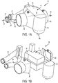
FIG. 1A is a perspective view of a heat exchange system according to an exemplary embodiment of the present invention; -
FIG. 1B is an exploded view ofFIG. 1A ; -
FIG. 2 is a schematic view of the heat exchange system ofFIGS. 1A-1B ; -
FIG. 3 is a perspective view of a water extractor according to an embodiment of the present invention; -
FIG. 4A is a schematic view of a water extractor according to another exemplary embodiment of the present invention; -
FIG. 4B is an enlarged view of a portion ofFIG. 4A ; -
FIG. 4C is a perspective view of the water extractor inFIG. 4A ; -
FIG. 5 is a schematic view of a water extractor, while depicting accumulation of humid air and water, according to an exemplary embodiment of the present invention; -
FIG. 6A is a schematic view of a water extractor according to yet another exemplary embodiment of the present invention; -
FIG. 6B is an enlarged view of a portion ofFIG. 6A ; -
FIG. 7 is a schematic view of a water extractor according to an additional exemplary embodiment of the present invention. - The following detailed description is of the best currently contemplated modes of carrying out the invention. The description is not to be taken in a limiting sense, but is made merely for the purpose of illustrating the general principles of the invention, since the scope of the invention is best defined by the appended claims.
- Various inventive features are described below that can each be used independently of one another or in combination with other features. However, any single inventive feature may not address any of the problems discussed above or may only address one of the problems discussed above. Further, one or more of the problems discussed above may not be fully addressed by any of the features described below.
- As used herein, the term "air" is intended to encompass the broader term "fluid". Thus, the term "air" and "fluid" are intended to be interchangeable.
- The present invention generally provides an integrated heat exchange system whereby a core of cross-flow heat exchange passages are shared by a reheater and a condenser. A first water extractor is directly downstream of a first pass of the condenser and directly interfaces the condenser so that fluid lines are eliminated between the condenser and the first water extractor. The first water extractor extracts humidity in the fluid (i.e., air) from the condenser. Concurrently, the first water extractor turns the humidified fluid back towards and into a second pass of the condenser. A second water extractor is directly downstream of the condenser and further extracts humidity in the fluid from the condenser. The second water extractor turns the further dehumidified fluid towards and into the reheater.
- As a result of the integration of the components herein, space requirements for a heat exchange system can be reduced by about 30% to about 50% of the volume of space otherwise required by past heat exchange system designs. The number of parts is reduced by about 40% to about 70%. The number of connections is reduced by about 25% to about 50%.
- In
FIGS. 1A-1B , aheat exchange system 10 is shown according to an exemplary embodiment of the present invention. Thesystem 10 may include a core 11 (that includes areheater 14 and a condenser 15), afirst water extractor 16, and asecond water extractor 19. - The
core 11 may include cross flow heat exchange passages. Thecore 11 can include common fins, bars, tube sheets and separator plates as known in the art. - In
FIG. 2 , thecore 11 may include a sharedportion 11a and anon-shared portion 11b, in an exemplary embodiment. For example, the sharedportion 11a may be a portion of thecore 11 wherein different components (or parts thereof) of theheat exchange system 10 may share common heat exchange passages. In thenon-shared portion 11b, different components of theheat exchange system 10 may not share common heat exchange passages. - In an embodiment, the shared
portion 11a may include thereheater 14 and thecondenser 15, each of which are in defined portions of thecore 11 but share some of the same heat exchange passages. In other words, one or more heat exchange passages may extend through thereheater 14 and thecondenser 15, wherein each of the passages may have two operational segments (though not physically segmented). One operational segment may function as part of a reheater and another operational segment may function as part of a condenser. - As shown in
FIG. 2 , thereheater 14 can operate on a cross flow of air (i.e., fluids) in heat exchange passages, as in known in the art. Thereheater 14 may include a humidifiedair inlet face 14a, a humidifiedair outlet face 14b, a dehumidifiedair inlet face 14c, and a dehumidifiedair outlet face 14d. Each of the foregoing faces may generally represent a plane or planar area that may define one or more of the boundaries or perimeters of thereheater 14. - The humidified
air inlet face 14a may connect to an air inlet or manifold 22 which may receive a humidifiedinlet air 17, such as air from a secondary heat exchanger of an aircraft ECS. Upon the humidifiedair 17 in thereheater 14 undergoing heat exchange, the humidifiedair outlet face 14b may pass reheater humidified air into thecondenser 15. - At the same time, the dehumidified
air inlet face 14c of thereheater 14 may receive further dehumidified air from thesecond water extractor 19 described below. Thereheater 14 can heat the dehumidified air and pass it through the dehumidifiedair outlet face 14d. Heated, dehumidifiedair 13 may flow into an air outlet ormanifold 21, and then to a turbine, for example, of an ECS of an aircraft. - The
condenser 15 can operate on a cross flow of fluids in the heat exchange passages as in known in the art. Thecondenser 15 may be directly downstream of the reheater, and may include a reheaterair inlet face 15a, a condensedair outlet face 15b, a dehumidifiedair inlet face 15c, and a dehumidifiedair outlet face 15d (FIG. 2 ). Each of the foregoing faces may generally represent a plane or planar area that may define one or more of the boundaries or perimeters of thecondenser 15. - The reheated
air inlet face 15a of thecondenser 15 may directly interface the humidifiedair outlet face 14b of thereheater 14. In other words, 15a is directly face-to-face with 14b in the absence of fluid connection lines otherwise used when a reheater and condenser are not integrated as a single component as in past designs. The reheatedair inlet face 15a of thecondenser 15 may receive humidified air from thereheater 14. - The
condenser 15 may condense the humidified air from thereheater 14. This may occur via heat exchange with aninlet air 12, such as from a turbine of an aircraft ECS. Theinlet air 12 may pass into an air inlet or manifold 20 that is connected to thecondenser 15. Condensed air may then exit from thecondenser 15, via the condensedair outlet face 15b. - As mentioned above, the
condenser 15 can share heat exchange passages with thereheater 14. As depicted inFIG. 2 , the sharing of heat exchange passages, in this exemplary embodiment, is only partial. The heat exchange passages that carryinlet air 17 through thereheater 14 can extend all through thecondenser 15 and up to thefirst water extractor 16 described below. However, the cross flow passages of thecondenser 15 that receive theinlet air 12 may not be shared with thereheater 14. Likewise, thecondenser 15 passages that receive dehumidified air from thefirst water extractor 16 may not be not shared with thereheater 14. And the passages in thereheater 14, that receive flow from thesecond water extractor 19 described below, may not be shared with thecondenser 15. - The
first water extractor 16, of theheat exchange system 10, may be directly downstream of thecondenser 15, and may include a condensedair inlet face 16a and a dehumidifiedair outlet face 16b (FIG. 2 ). Each of the foregoing faces may generally represent a plane or planar area that may define the boundaries or perimeters of thewater extractor 16. - The condensed
air inlet face 16a of thewater extractor 16 may directly interface the condensedair outlet face 15b of thecondenser 15. In other words, 16a is directly face-to-face with 15b in the absence of fluid connection lines between them. The condensedair inlet face 16a of thewater extractor 16 may receive condensed water and air from thecondenser 15. -
FIG. 3 is a perspective view of another embodiment of a first water extractor 16' which is similar to thewater extractor 16 inFIGS. 1A-1B and2 . The first water extractor 16' includes a condensedair inlet face 16a' and a dehumidifiedair outlet face 16b'. Each of the foregoing faces may generally represent a plane or planar area that may define part of the boundaries or perimeters of the water extractor 16'. The water extractor 16' may further include a firstoutside wall 16c' that may define a part of the perimeter of the water extractor 16'. One or more firstinterior walls 16d' may have a curved configuration and/or semi-circular configuration. The firstinterior walls 16d' may be positioned from or near theinlet face 16a' and to or near theoutlet face 16b'. As further described below, a manifold 16h' may collect water and purge the collected water via anoutlet 16e'. -
FIGS. 4A-4C depict yet another exemplary embodiment of afirst water extractor 40. Thefirst water extractor 40 may, upon receiving condensed water andair 24 at aninlet face 40a, turn the condensed water andair 24 around a center area oraxis 40q, and exit, as condensed water andair 25, at anoutlet face 40b to thecondenser 15. In this exemplary embodiment, the condensed water andair 24 may be turned 180°, or substantially about 180°. Concurrently as the condensed water andair 24 is turned, thewater extractor 40 can remove condensed water from the air, such as in the form ofwater droplets 26a, via inertia. - In an exemplary embodiment, the
first water extractor 40 may include a firstoutside wall 40c. Thefirst water extractor 40 may also include a plurality of firstinterior walls 40d that are radially inward of the firstoutside wall 40c. The firstinterior walls 40d may be curved and/or semi-circular, and may be concentric to one another in a radial direction. In various embodiments, the firstinterior walls 40d may or may not be equally spaced, radially, from one another. - In
FIGS. 4A and4C , theinterior walls 40d can be configured to provide one or more chambers (i.e., low pressure zones) 40m. Thechambers 40m may all have the same configuration or some/all may differ in configuration from one another. - The
chambers 40m may be arranged in one ormore groups 40k (i.e., low pressure zones) ofchambers 40m. The number ofchambers 40m in eachchamber group 40k may be the same or some/all may differ from one another. - In embodiments, one or more of the
chamber groups 40k may be configured in one ormore chamber layers 40n (i.e., low pressure zones) that may be positioned concentric to one another in a radial direction. Eachchamber layer 40n may have a curved or semi-circular configuration. However, the chamber layers 40n may or may not have different configurations. - In embodiments, the
chambers 40m, in one or more of thechamber groups 40k, may be positioned in an end-to-end relationship. However, the present invention contemplates that the chambers can be positioned in a side-by-side relationship or in other orientations. - In
FIGS. 4A and 4B , in embodiments, one or more of thechambers 40m may have an oblong shape and may be configured with a length longer than a width. Some or all of thechambers 40m may have the same or different configurations. - In embodiments, one or
more chambers 40m may be configured with a respective chamber inlet 40i (i.e., low pressure zone). Accordingly, the inlets 40i may be arranged in and be part of the chamber layers 40n. - One or more of the chamber inlets 40i can be positioned along a side (or both opposing sides) of a
respective flow channel 40p described below, thus providing an inlet layer. In embodiments, the chamber inlets 40i can be equally or unequally spaced from one another along therespective flow channel 40p. Thereby, the chamber inlets 40i can enable and promote the flow of humid air into one ormore chambers 40m, as further described below. - The one or more chamber inlets 40i may be parts of one or more
interior walls 40d. In embodiments, a respective chamber inlet 40i may be on opposite lateral sides of asingle chamber 40m. In embodiments, one or more of the chamber inlets 40i may include twointerior wall portions wall portions - In embodiments, one or more of the
wall portions 40h may have a step configuration. One or more of thewall portions 40h may extend into arespective flow channel 40p. A distal end of thewall portion 40h that is in a flow channel may be described as a "shave off edge." - Still referring to
FIGS. 4A and 4B , thehumid air 24 can enter thewater extractor 40 and travel along one or more flow paths (i.e., high pressure zones) 26b that flow in adirection 26c. One ormore flow paths 26b may be in one or more radially positionedflow channels 40p (i.e., high pressure zones). In embodiments, oneflow channel 40p includesmultiple flow paths 26b. Eachflow channel 40p may have a curved or semi-circular configuration, and may be concentric to one another in a radial direction. However, not all of theflow channels 40p may have the same configuration. In embodiments, oneflow channel 40p may be positioned to alternate with onechamber layer 40n in a stacked or radially extending configuration. - In one or more of the flow paths (high pressure zones) 26b and/or
flow channels 40p (high pressure zones), the humid air may be at a pressure higher than the pressure in one or more of the chambers (low pressure zones) 40m and/orchamber layers 40n (low pressure zones). This pressure differential may be particularly present between achamber 40m and an immediatelyadjacent flow path 26b. In other words, the pressure differential may be particularly present between achamber layer 40n and an immediatelyadjacent flow channel 40p. The pressure differential may enable and promote the humid air in aflow path 26b to enter one or more of the adjacent chamber inlets 40i. -
FIG. 5 is an exemplary embodiment of a first water extractor 50 which is similar in design to the embodiment ofFIGS. 4A-4C .FIG. 5 is intended to depict the location of humid air and water, though the invention is not intended to be limited by this characterization. A flow can enter the first water extractor 50 at aninlet face 50a and exit there from at anoutlet face 50b. Upon the flow entering the water extractor 50, the flow can continue in one ormore flow channels 50p of flow paths. In the flow channels, the humid air and water droplets are relatively randomly mixed. - One or
more chamber inlets 50i enable and promote a portion of the flow to enter one ormore chambers 50m of one ormore chamber layers 50n. In achamber 50m, humid air may accumulate within the chamber. Water may tend to accumulate at a downstream end of thechamber 50m. Between the two ends of thechamber 50m, a mixture of humid air and water droplets are relatively randomly mixed. - Though not depicted in
FIG. 5 , accumulated water in one or more of thechambers 50m may travel downward due to gravity. After traveling downward, the water may be received in a manifold and expelled, as shown in the embodiment ofFIG. 3 . -
FIGS. 6A-6B depict another embodiment of a first water extractor 60 and which is similar in design to the embodiment ofFIGS. 4A-4C . In the extractor 60,chambers 60m-1 are immediately adjacent anoutside wall 60c.Other chambers 60m-2 are radially away from theoutside wall 60c and adjacent to interior walls 60d. In this embodiment, the configurations of thechambers 60m-1 are different from the configurations ofchambers 60m-2, at least to the extent of their widths. - Also, in this embodiment, one or more
interior chambers 60m-2 may have a chamber inlet 60i-1 formed by awall portion 60h-1, but only on one lateral side of thechamber 60m-2 so that humid air and water, from a flow channel, may flow into thechamber 60m-2 from only one lateral side. On an opposite lateral side of thatchamber 60m-2, a wall portion or ramp 60h-2 may form an inlet or pocket 60i-2 but it may be closed to thechamber 60m-2 so that humid air and water may not flow into thechamber 60m-2 from that one side. Thus, in embodiments, along any oneflow channel 60p that extends between twochamber layers 60n, open inlets 60i-1 may be located along one side of the flow channel, while closed inlets 60i-2 may be located along an opposite side the flow channel. That is in contrast to the embodiment ofFIGS. 4A-4C wherein open chamber inlets are along both sides of a flow channel. -
FIG. 7 depicts another embodiment of afirst water extractor 70 and which is similar in design to the embodiment ofFIGS. 6A-6B . In thewater extractor 70, however, one or more of the interior walls (and/or one or more chambers and/or chamber inlets) are twisted about acenter axis 70q (i.e., twisted in a vertical direction) to form a type of helix configuration. Thereby, avertical axis 70s along which the interior wall lies is no longer parallel to thecenter axis 70q or direction of gravity, such as in the embodiment ofFIGS. 4A-4C . Instead, the vertical axis lies non-parallel to thecenter axis 70q or direction of gravity. This can enable and promote downward movement of collected water in the chambers and into the manifold for exit. In contrast, the other embodiments above rely primarily on gravity to move the collected water downwards. - In any of the embodiments herein, the number and configuration of chambers, inlets, flow channels and flow layers may be different.
- Turning back to
FIG. 2 , dehumidifiedair 25 from thefirst water extractor 16 exits, via the dehumidifiedair outlet face 16b, and flows back into thecondenser 15 that is directly downstream of thefirst water extractor 16. The dehumidifiedair inlet face 15c of thecondenser 15 directly interfaces (i.e., is directly face-to-face with) the dehumidifiedair outlet face 16b of thewater extractor 16. Thereby, at such interface, no flow connection lines are needed between thefirst water extractor 16 and thecondenser 15. - In the
condenser 15, the dehumidified air may undergo heat exchange with theinlet air 12, and exit asoutlet air 18, via an air outlet ormanifold 23. Theoutlet air 18 may flow to a mixer, for example, of an ECS of an aircraft. The dehumidified air may exit thecondenser 15 as condensed, dehumidified air, via the dehumidifiedair outlet face 15d. - A
second water extractor 19 can be directly downstream of and directly interfacing thecondenser 15. A condensedair inlet face 19a of thewater extractor 19 may be directly face-to-face with the dehumidifiedair outlet face 15d of thecondenser 15. Thereby, flow lines are eliminated between thewater extractor 19 and thecondenser 15. - The
second water extractor 19 can be similar in design and function to thefirst water extractor 16. Upon receiving the dehumidified, condensed water and air from thecondenser 15, thesecond water extractor 19 can turn the condensed water and air which, in this case, is towards thereheater 14. In this exemplary embodiment, the condensed air can be turned 90°, or substantially about 90°. Concurrently as the condensed water and air is turned, thewater extractor 19 can remove water from the condensed water and air, via inertia. - From the
second water extractor 19, further dehumidified condensed air may exit, via the dehumidifiedoutlet face 19b, and enter thereheater 14, via the dehumidifiedair inlet face 14c. In thereheater 14, the further dehumidified condensed air may undergo heat exchange with theinlet air 17 and exit as theoutlet air 13. - It should be understood, of course, that the foregoing relates to exemplary embodiments of the invention and that modifications may be made without departing from the scope of the invention as set forth in the following claims.
-
- 1. A heat exchanger system (10), comprising:
- a reheater (14);
- a condenser (15) that is downstream of and directly interfaces the reheater;
- a first water extractor (16) that is downstream of and directly interfaces the condenser, wherein the first water extractor includes:
- a group of low pressure chambers (40m);
- wherein at least one chamber is configured to promote a high pressure flow to enter the at least one chamber; and
- a second water extractor (19) that is downstream of and directly interfaces the condenser, and is upstream of and directly interfaces the reheater.
- 2. The system of 1, wherein the reheater and the condenser are part of a common core of cross flow passages.
- 3. The system of 1, wherein the condenser shares a heat exchange passage with the reheater.
- 4. The system of 1, wherein the condenser includes a first pass directly downstream of the reheater.
- 5. The system of 1, wherein the condenser includes a second pass directly downstream of the first water extractor.
- 6. The system of 1, wherein the first water extractor includes a plurality of groups of chambers, and wherein the groups are configured in radially extending layers (40n).
- 7. The system of 1, further comprising alternating layers of chambers and channels of flow (40p).
Claims (9)
- A water extractor (16/16'/19/40/50/60/70), comprising:a plurality of layers of chambers (40n/50n/60n), each layer of the plurality of layers including one or more chambers (40m/60m 1/60m 2); andone or more flow channels (40p/50p/60p) through which a flow enters the water extractor and flows in a direction (26c) towards an outlet face (16b/16b'/19b/40b/50b) of the water extractor,wherein the plurality of layers and the one or more flow channels are positioned to alternate with one another, andwherein the chambers each include one or more open inlets (40i/50i/60i 1) configured to enable a portion of the flow to enter the one or more chambers.
- The water extractor of claim 1, wherein the one or more chambers includes a plurality of chambers, and wherein the chambers are arranged in one or more groups (40k), wherein at least one group includes at least two chambers positioned in an end to end relationship.
- The water extractor of any one of claims 1 or 2, wherein only one lateral side of each chamber (60m-2) of the one or more chambers forms an inlet.
- The water extractor of any one of claims 1 or 2, wherein opposite lateral sides of each chamber (40m) of the one or more chambers forms an inlet (40i).
- The water extractor of any one of claims 1-4, wherein the plurality of layers and the one or more flow channels are positioned to alternate with one another in a radially extending configuration.
- The water extractor of any one of claims 1-5, wherein the one or more chambers are configured collect water and allow the collected water to travel from the one or more chambers of the water extractor to a manifold (16h').
- The water extractor of any one of claims 1-6, further comprising one or more walls defining the one or more chambers, wherein the one or more walls twist about a center axis (40q/70q) of the water extractor.
- The water extractor of any one of claims 1-7, wherein the one or more flow channels comprise one or more turns that are at least substantially about 90° in the direction towards the outlet face of the water extractor.
- The water extractor of any one of claims 1-8, wherein the water extractor is downstream of and interfaces a condenser.
Applications Claiming Priority (2)
| Application Number | Priority Date | Filing Date | Title |
|---|---|---|---|
| US15/728,316 US10960332B2 (en) | 2017-10-09 | 2017-10-09 | High pressure water extraction device with shave off edge that feeds a low pressure chamber and internal helix feature to improve water collection and drainage |
| EP18199194.4A EP3467392B1 (en) | 2017-10-09 | 2018-10-08 | Improved high pressure water extraction device with shave off edge that feeds a low pressure chamber and internal helix feature to improve water collection and drainage |
Related Parent Applications (1)
| Application Number | Title | Priority Date | Filing Date |
|---|---|---|---|
| EP18199194.4A Division EP3467392B1 (en) | 2017-10-09 | 2018-10-08 | Improved high pressure water extraction device with shave off edge that feeds a low pressure chamber and internal helix feature to improve water collection and drainage |
Publications (2)
| Publication Number | Publication Date |
|---|---|
| EP3690335A1 true EP3690335A1 (en) | 2020-08-05 |
| EP3690335B1 EP3690335B1 (en) | 2022-11-30 |
Family
ID=63794414
Family Applications (2)
| Application Number | Title | Priority Date | Filing Date |
|---|---|---|---|
| EP18199194.4A Active EP3467392B1 (en) | 2017-10-09 | 2018-10-08 | Improved high pressure water extraction device with shave off edge that feeds a low pressure chamber and internal helix feature to improve water collection and drainage |
| EP20162227.1A Active EP3690335B1 (en) | 2017-10-09 | 2018-10-08 | Improved high pressure water extraction device with shave off edge that feeds a low pressure chamber to improve water collection and drainage |
Family Applications Before (1)
| Application Number | Title | Priority Date | Filing Date |
|---|---|---|---|
| EP18199194.4A Active EP3467392B1 (en) | 2017-10-09 | 2018-10-08 | Improved high pressure water extraction device with shave off edge that feeds a low pressure chamber and internal helix feature to improve water collection and drainage |
Country Status (2)
| Country | Link |
|---|---|
| US (2) | US10960332B2 (en) |
| EP (2) | EP3467392B1 (en) |
Families Citing this family (8)
| Publication number | Priority date | Publication date | Assignee | Title |
|---|---|---|---|---|
| IT201700119692A1 (en) * | 2017-10-23 | 2019-04-23 | Ceccato Aria Compressa S R L | PERFECTED HEAT EXCHANGER AND AIR DRYING SYSTEM USING THE ABOVE HEAT EXCHANGER |
| CN113663420B (en) * | 2021-09-29 | 2022-09-13 | 万博新材料科技(南通)有限公司 | Waste gas purification equipment for water-based resin processing |
| US12084188B2 (en) * | 2021-11-30 | 2024-09-10 | Hamilton Sundstrand Corporation | Mid-pressure water collector for environmental control system |
| CN114877598B (en) * | 2022-06-09 | 2024-06-11 | 海信(山东)冰箱有限公司 | Air guide structure and combined refrigerator |
| US12311300B2 (en) * | 2022-08-03 | 2025-05-27 | Hamilton Sundstrand Corporation | Mid-pressure water separation for environmental control system |
| US12551829B2 (en) * | 2023-03-28 | 2026-02-17 | Hamilton Sundstrand Space Systems International, Inc. | Fluid separation and condensate control systems |
| US20240327040A1 (en) * | 2023-03-28 | 2024-10-03 | Hamilton Sundstrand Space Systems International, Inc. | Fluid separation and condensate control systems |
| US20250108322A1 (en) * | 2023-10-03 | 2025-04-03 | Hamilton Sundstrand Corporation | Mid-pressure water separation for environmental control system |
Citations (3)
| Publication number | Priority date | Publication date | Assignee | Title |
|---|---|---|---|---|
| US20100326026A1 (en) * | 2009-06-24 | 2010-12-30 | Industrial Process Products Ltd. | Vane-type separator |
| US20140007774A1 (en) * | 2012-07-03 | 2014-01-09 | Balke-Durr Gmbh | Lamellar separator with catch basin |
| US20170045243A1 (en) * | 2015-08-14 | 2017-02-16 | Honeywell International Inc. | Water extractor device using scuppers |
Family Cites Families (8)
| Publication number | Priority date | Publication date | Assignee | Title |
|---|---|---|---|---|
| US1678844A (en) * | 1924-05-31 | 1928-07-31 | Blaw Knox Co | Fluid separator |
| SE410145B (en) * | 1973-07-18 | 1979-10-01 | Steinmueller Gmbh L & C | DEVICE FOR SEPARATION OF WOOD SHOES FROM A GASY MEDIUM IN COLLECTION GUTTER |
| DE3627555C1 (en) | 1986-08-14 | 1987-08-06 | Dieter Prof Dr-Ing Wurz | Liquid separator |
| DE3880301D1 (en) | 1988-02-27 | 1993-05-19 | Via Gmbh | LIQUID SEPARATOR. |
| US5104431A (en) * | 1990-06-20 | 1992-04-14 | Peerless Manufacturing Company | High capacity vane |
| DE19911252C1 (en) * | 1999-02-25 | 2000-11-16 | Man B & W Diesel As Kopenhagen | Water separator for engine, has perforation formed in corresponding wall in inner side of collection chamber facing flow path consists of cyclone separator segment |
| JP2003144824A (en) * | 2001-11-06 | 2003-05-20 | Mitsubishi Heavy Ind Ltd | Moisture separator and steam generator |
| US7470300B2 (en) * | 2005-12-07 | 2008-12-30 | Honeywell International Inc. | Duct wall water extractor |
-
2017
- 2017-10-09 US US15/728,316 patent/US10960332B2/en not_active Expired - Fee Related
-
2018
- 2018-10-08 EP EP18199194.4A patent/EP3467392B1/en active Active
- 2018-10-08 EP EP20162227.1A patent/EP3690335B1/en active Active
-
2021
- 2021-03-23 US US17/301,049 patent/US20210229013A1/en not_active Abandoned
Patent Citations (3)
| Publication number | Priority date | Publication date | Assignee | Title |
|---|---|---|---|---|
| US20100326026A1 (en) * | 2009-06-24 | 2010-12-30 | Industrial Process Products Ltd. | Vane-type separator |
| US20140007774A1 (en) * | 2012-07-03 | 2014-01-09 | Balke-Durr Gmbh | Lamellar separator with catch basin |
| US20170045243A1 (en) * | 2015-08-14 | 2017-02-16 | Honeywell International Inc. | Water extractor device using scuppers |
Also Published As
| Publication number | Publication date |
|---|---|
| EP3467392A1 (en) | 2019-04-10 |
| US10960332B2 (en) | 2021-03-30 |
| US20210229013A1 (en) | 2021-07-29 |
| EP3467392B1 (en) | 2020-04-01 |
| US20190105590A1 (en) | 2019-04-11 |
| EP3690335B1 (en) | 2022-11-30 |
Similar Documents
| Publication | Publication Date | Title |
|---|---|---|
| EP3690335B1 (en) | Improved high pressure water extraction device with shave off edge that feeds a low pressure chamber to improve water collection and drainage | |
| CN104303000B (en) | Heat exchanger | |
| US8250879B2 (en) | Dual-circuit chiller with two-pass heat exchanger in a series counterflow arrangement | |
| EP2482006A1 (en) | Heat exchanger | |
| US10254022B2 (en) | Condenser with a refrigerant supply for an air-conditioning circuit | |
| WO2014205799A1 (en) | Microchannel heat exchangers | |
| EP2913618B1 (en) | Heat exchanger | |
| US8943854B2 (en) | Heat exchanger and air condition system | |
| EP1191296A2 (en) | Circuiting arrangement for a closed circuit cooling tower | |
| SE514092C2 (en) | Apparatus for treating a gas | |
| ES2440241T3 (en) | Improved refrigerant distribution in parallel flow heat exchanger manifolds | |
| US10024557B2 (en) | Water extractor device using scuppers | |
| EP3042127B1 (en) | Integrated separator-distributor for falling film evaporator | |
| US20100115984A1 (en) | Dual-circuit series counterflow chiller with intermediate waterbox | |
| CN107044749A (en) | For heating, the lubricant separator of ventilating and air conditioning system | |
| US20090188650A1 (en) | Liquid distribution in an evaporative heat rejection system | |
| WO2014197002A1 (en) | Distributor for use in a vapor compression system | |
| US9067163B2 (en) | Particle separator | |
| US10697717B2 (en) | Water head for an evaporator | |
| CN204345972U (en) | Passenger car HVAC system and microchannel heat exchanger used therewith | |
| KR102734898B1 (en) | Heat exchanger and blower module including it | |
| WO2018211136A1 (en) | Phase separator comprising a flow disruptor | |
| CN118776356A (en) | Heat exchanger and air conditioner | |
| JP6639959B2 (en) | Heat exchange system | |
| CN118816620A (en) | Turbine group, heat exchanger and air conditioner |
Legal Events
| Date | Code | Title | Description |
|---|---|---|---|
| PUAI | Public reference made under article 153(3) epc to a published international application that has entered the european phase |
Free format text: ORIGINAL CODE: 0009012 |
|
| STAA | Information on the status of an ep patent application or granted ep patent |
Free format text: STATUS: REQUEST FOR EXAMINATION WAS MADE |
|
| 17P | Request for examination filed |
Effective date: 20200310 |
|
| AC | Divisional application: reference to earlier application |
Ref document number: 3467392 Country of ref document: EP Kind code of ref document: P |
|
| AK | Designated contracting states |
Kind code of ref document: A1 Designated state(s): AL AT BE BG CH CY CZ DE DK EE ES FI FR GB GR HR HU IE IS IT LI LT LU LV MC MK MT NL NO PL PT RO RS SE SI SK SM TR |
|
| RIC1 | Information provided on ipc code assigned before grant |
Ipc: B01D 45/08 20060101ALI20220318BHEP Ipc: B01D 53/26 20060101ALI20220318BHEP Ipc: B04C 3/06 20060101ALI20220318BHEP Ipc: F25B 9/00 20060101ALI20220318BHEP Ipc: B64D 13/08 20060101ALI20220318BHEP Ipc: B64D 13/06 20060101ALI20220318BHEP Ipc: B64D 13/02 20060101ALI20220318BHEP Ipc: F28D 9/00 20060101ALI20220318BHEP Ipc: F28F 17/00 20060101ALI20220318BHEP Ipc: F24F 5/00 20060101AFI20220318BHEP |
|
| GRAP | Despatch of communication of intention to grant a patent |
Free format text: ORIGINAL CODE: EPIDOSNIGR1 |
|
| STAA | Information on the status of an ep patent application or granted ep patent |
Free format text: STATUS: GRANT OF PATENT IS INTENDED |
|
| INTG | Intention to grant announced |
Effective date: 20220429 |
|
| GRAS | Grant fee paid |
Free format text: ORIGINAL CODE: EPIDOSNIGR3 |
|
| GRAA | (expected) grant |
Free format text: ORIGINAL CODE: 0009210 |
|
| STAA | Information on the status of an ep patent application or granted ep patent |
Free format text: STATUS: THE PATENT HAS BEEN GRANTED |
|
| AC | Divisional application: reference to earlier application |
Ref document number: 3467392 Country of ref document: EP Kind code of ref document: P |
|
| AK | Designated contracting states |
Kind code of ref document: B1 Designated state(s): AL AT BE BG CH CY CZ DE DK EE ES FI FR GB GR HR HU IE IS IT LI LT LU LV MC MK MT NL NO PL PT RO RS SE SI SK SM TR |
|
| REG | Reference to a national code |
Ref country code: CH Ref legal event code: EP Ref country code: GB Ref legal event code: FG4D |
|
| REG | Reference to a national code |
Ref country code: AT Ref legal event code: REF Ref document number: 1534944 Country of ref document: AT Kind code of ref document: T Effective date: 20221215 |
|
| REG | Reference to a national code |
Ref country code: IE Ref legal event code: FG4D |
|
| REG | Reference to a national code |
Ref country code: DE Ref legal event code: R096 Ref document number: 602018043861 Country of ref document: DE |
|
| REG | Reference to a national code |
Ref country code: LT Ref legal event code: MG9D |
|
| REG | Reference to a national code |
Ref country code: NL Ref legal event code: MP Effective date: 20221130 |
|
| PG25 | Lapsed in a contracting state [announced via postgrant information from national office to epo] |
Ref country code: SE Free format text: LAPSE BECAUSE OF FAILURE TO SUBMIT A TRANSLATION OF THE DESCRIPTION OR TO PAY THE FEE WITHIN THE PRESCRIBED TIME-LIMIT Effective date: 20221130 Ref country code: PT Free format text: LAPSE BECAUSE OF FAILURE TO SUBMIT A TRANSLATION OF THE DESCRIPTION OR TO PAY THE FEE WITHIN THE PRESCRIBED TIME-LIMIT Effective date: 20230331 Ref country code: NO Free format text: LAPSE BECAUSE OF FAILURE TO SUBMIT A TRANSLATION OF THE DESCRIPTION OR TO PAY THE FEE WITHIN THE PRESCRIBED TIME-LIMIT Effective date: 20230228 Ref country code: LT Free format text: LAPSE BECAUSE OF FAILURE TO SUBMIT A TRANSLATION OF THE DESCRIPTION OR TO PAY THE FEE WITHIN THE PRESCRIBED TIME-LIMIT Effective date: 20221130 Ref country code: FI Free format text: LAPSE BECAUSE OF FAILURE TO SUBMIT A TRANSLATION OF THE DESCRIPTION OR TO PAY THE FEE WITHIN THE PRESCRIBED TIME-LIMIT Effective date: 20221130 Ref country code: ES Free format text: LAPSE BECAUSE OF FAILURE TO SUBMIT A TRANSLATION OF THE DESCRIPTION OR TO PAY THE FEE WITHIN THE PRESCRIBED TIME-LIMIT Effective date: 20221130 |
|
| REG | Reference to a national code |
Ref country code: AT Ref legal event code: MK05 Ref document number: 1534944 Country of ref document: AT Kind code of ref document: T Effective date: 20221130 |
|
| PG25 | Lapsed in a contracting state [announced via postgrant information from national office to epo] |
Ref country code: RS Free format text: LAPSE BECAUSE OF FAILURE TO SUBMIT A TRANSLATION OF THE DESCRIPTION OR TO PAY THE FEE WITHIN THE PRESCRIBED TIME-LIMIT Effective date: 20221130 Ref country code: PL Free format text: LAPSE BECAUSE OF FAILURE TO SUBMIT A TRANSLATION OF THE DESCRIPTION OR TO PAY THE FEE WITHIN THE PRESCRIBED TIME-LIMIT Effective date: 20221130 Ref country code: LV Free format text: LAPSE BECAUSE OF FAILURE TO SUBMIT A TRANSLATION OF THE DESCRIPTION OR TO PAY THE FEE WITHIN THE PRESCRIBED TIME-LIMIT Effective date: 20221130 Ref country code: IS Free format text: LAPSE BECAUSE OF FAILURE TO SUBMIT A TRANSLATION OF THE DESCRIPTION OR TO PAY THE FEE WITHIN THE PRESCRIBED TIME-LIMIT Effective date: 20230330 Ref country code: HR Free format text: LAPSE BECAUSE OF FAILURE TO SUBMIT A TRANSLATION OF THE DESCRIPTION OR TO PAY THE FEE WITHIN THE PRESCRIBED TIME-LIMIT Effective date: 20221130 Ref country code: GR Free format text: LAPSE BECAUSE OF FAILURE TO SUBMIT A TRANSLATION OF THE DESCRIPTION OR TO PAY THE FEE WITHIN THE PRESCRIBED TIME-LIMIT Effective date: 20230301 |
|
| PG25 | Lapsed in a contracting state [announced via postgrant information from national office to epo] |
Ref country code: NL Free format text: LAPSE BECAUSE OF FAILURE TO SUBMIT A TRANSLATION OF THE DESCRIPTION OR TO PAY THE FEE WITHIN THE PRESCRIBED TIME-LIMIT Effective date: 20221130 |
|
| P01 | Opt-out of the competence of the unified patent court (upc) registered |
Effective date: 20230525 |
|
| PG25 | Lapsed in a contracting state [announced via postgrant information from national office to epo] |
Ref country code: SM Free format text: LAPSE BECAUSE OF FAILURE TO SUBMIT A TRANSLATION OF THE DESCRIPTION OR TO PAY THE FEE WITHIN THE PRESCRIBED TIME-LIMIT Effective date: 20221130 Ref country code: RO Free format text: LAPSE BECAUSE OF FAILURE TO SUBMIT A TRANSLATION OF THE DESCRIPTION OR TO PAY THE FEE WITHIN THE PRESCRIBED TIME-LIMIT Effective date: 20221130 Ref country code: EE Free format text: LAPSE BECAUSE OF FAILURE TO SUBMIT A TRANSLATION OF THE DESCRIPTION OR TO PAY THE FEE WITHIN THE PRESCRIBED TIME-LIMIT Effective date: 20221130 Ref country code: DK Free format text: LAPSE BECAUSE OF FAILURE TO SUBMIT A TRANSLATION OF THE DESCRIPTION OR TO PAY THE FEE WITHIN THE PRESCRIBED TIME-LIMIT Effective date: 20221130 Ref country code: CZ Free format text: LAPSE BECAUSE OF FAILURE TO SUBMIT A TRANSLATION OF THE DESCRIPTION OR TO PAY THE FEE WITHIN THE PRESCRIBED TIME-LIMIT Effective date: 20221130 Ref country code: AT Free format text: LAPSE BECAUSE OF FAILURE TO SUBMIT A TRANSLATION OF THE DESCRIPTION OR TO PAY THE FEE WITHIN THE PRESCRIBED TIME-LIMIT Effective date: 20221130 |
|
| PG25 | Lapsed in a contracting state [announced via postgrant information from national office to epo] |
Ref country code: SK Free format text: LAPSE BECAUSE OF FAILURE TO SUBMIT A TRANSLATION OF THE DESCRIPTION OR TO PAY THE FEE WITHIN THE PRESCRIBED TIME-LIMIT Effective date: 20221130 Ref country code: AL Free format text: LAPSE BECAUSE OF FAILURE TO SUBMIT A TRANSLATION OF THE DESCRIPTION OR TO PAY THE FEE WITHIN THE PRESCRIBED TIME-LIMIT Effective date: 20221130 |
|
| REG | Reference to a national code |
Ref country code: DE Ref legal event code: R097 Ref document number: 602018043861 Country of ref document: DE |
|
| PLBE | No opposition filed within time limit |
Free format text: ORIGINAL CODE: 0009261 |
|
| STAA | Information on the status of an ep patent application or granted ep patent |
Free format text: STATUS: NO OPPOSITION FILED WITHIN TIME LIMIT |
|
| 26N | No opposition filed |
Effective date: 20230831 |
|
| PG25 | Lapsed in a contracting state [announced via postgrant information from national office to epo] |
Ref country code: SI Free format text: LAPSE BECAUSE OF FAILURE TO SUBMIT A TRANSLATION OF THE DESCRIPTION OR TO PAY THE FEE WITHIN THE PRESCRIBED TIME-LIMIT Effective date: 20221130 |
|
| REG | Reference to a national code |
Ref country code: DE Ref legal event code: R119 Ref document number: 602018043861 Country of ref document: DE |
|
| PG25 | Lapsed in a contracting state [announced via postgrant information from national office to epo] |
Ref country code: IT Free format text: LAPSE BECAUSE OF FAILURE TO SUBMIT A TRANSLATION OF THE DESCRIPTION OR TO PAY THE FEE WITHIN THE PRESCRIBED TIME-LIMIT Effective date: 20221130 Ref country code: MC Free format text: LAPSE BECAUSE OF FAILURE TO SUBMIT A TRANSLATION OF THE DESCRIPTION OR TO PAY THE FEE WITHIN THE PRESCRIBED TIME-LIMIT Effective date: 20221130 |
|
| REG | Reference to a national code |
Ref country code: CH Ref legal event code: PL |
|
| REG | Reference to a national code |
Ref country code: BE Ref legal event code: MM Effective date: 20231031 |
|
| PG25 | Lapsed in a contracting state [announced via postgrant information from national office to epo] |
Ref country code: LU Free format text: LAPSE BECAUSE OF NON-PAYMENT OF DUE FEES Effective date: 20231008 |
|
| GBPC | Gb: european patent ceased through non-payment of renewal fee |
Effective date: 20231008 |
|
| PG25 | Lapsed in a contracting state [announced via postgrant information from national office to epo] |
Ref country code: LU Free format text: LAPSE BECAUSE OF NON-PAYMENT OF DUE FEES Effective date: 20231008 |
|
| PG25 | Lapsed in a contracting state [announced via postgrant information from national office to epo] |
Ref country code: GB Free format text: LAPSE BECAUSE OF NON-PAYMENT OF DUE FEES Effective date: 20231008 |
|
| PG25 | Lapsed in a contracting state [announced via postgrant information from national office to epo] |
Ref country code: CH Free format text: LAPSE BECAUSE OF NON-PAYMENT OF DUE FEES Effective date: 20231031 |
|
| PG25 | Lapsed in a contracting state [announced via postgrant information from national office to epo] |
Ref country code: GB Free format text: LAPSE BECAUSE OF NON-PAYMENT OF DUE FEES Effective date: 20231008 Ref country code: FR Free format text: LAPSE BECAUSE OF NON-PAYMENT OF DUE FEES Effective date: 20231031 Ref country code: DE Free format text: LAPSE BECAUSE OF NON-PAYMENT OF DUE FEES Effective date: 20240501 Ref country code: CH Free format text: LAPSE BECAUSE OF NON-PAYMENT OF DUE FEES Effective date: 20231031 |
|
| PG25 | Lapsed in a contracting state [announced via postgrant information from national office to epo] |
Ref country code: BE Free format text: LAPSE BECAUSE OF NON-PAYMENT OF DUE FEES Effective date: 20231031 |
|
| PG25 | Lapsed in a contracting state [announced via postgrant information from national office to epo] |
Ref country code: IE Free format text: LAPSE BECAUSE OF NON-PAYMENT OF DUE FEES Effective date: 20231008 |
|
| PG25 | Lapsed in a contracting state [announced via postgrant information from national office to epo] |
Ref country code: IE Free format text: LAPSE BECAUSE OF NON-PAYMENT OF DUE FEES Effective date: 20231008 |
|
| PG25 | Lapsed in a contracting state [announced via postgrant information from national office to epo] |
Ref country code: BG Free format text: LAPSE BECAUSE OF FAILURE TO SUBMIT A TRANSLATION OF THE DESCRIPTION OR TO PAY THE FEE WITHIN THE PRESCRIBED TIME-LIMIT Effective date: 20221130 |
|
| PG25 | Lapsed in a contracting state [announced via postgrant information from national office to epo] |
Ref country code: BG Free format text: LAPSE BECAUSE OF FAILURE TO SUBMIT A TRANSLATION OF THE DESCRIPTION OR TO PAY THE FEE WITHIN THE PRESCRIBED TIME-LIMIT Effective date: 20221130 |
|
| PG25 | Lapsed in a contracting state [announced via postgrant information from national office to epo] |
Ref country code: CY Free format text: LAPSE BECAUSE OF FAILURE TO SUBMIT A TRANSLATION OF THE DESCRIPTION OR TO PAY THE FEE WITHIN THE PRESCRIBED TIME-LIMIT; INVALID AB INITIO Effective date: 20181008 |
|
| PG25 | Lapsed in a contracting state [announced via postgrant information from national office to epo] |
Ref country code: HU Free format text: LAPSE BECAUSE OF FAILURE TO SUBMIT A TRANSLATION OF THE DESCRIPTION OR TO PAY THE FEE WITHIN THE PRESCRIBED TIME-LIMIT; INVALID AB INITIO Effective date: 20181008 |
|
| PG25 | Lapsed in a contracting state [announced via postgrant information from national office to epo] |
Ref country code: TR Free format text: LAPSE BECAUSE OF FAILURE TO SUBMIT A TRANSLATION OF THE DESCRIPTION OR TO PAY THE FEE WITHIN THE PRESCRIBED TIME-LIMIT Effective date: 20221130 |