EP3690314A1 - Gas burner for a gas hob - Google Patents
Gas burner for a gas hob Download PDFInfo
- Publication number
- EP3690314A1 EP3690314A1 EP20151949.3A EP20151949A EP3690314A1 EP 3690314 A1 EP3690314 A1 EP 3690314A1 EP 20151949 A EP20151949 A EP 20151949A EP 3690314 A1 EP3690314 A1 EP 3690314A1
- Authority
- EP
- European Patent Office
- Prior art keywords
- gas
- injector nozzle
- polynomial function
- circumferential wall
- longitudinal axis
- Prior art date
- Legal status (The legal status is an assumption and is not a legal conclusion. Google has not performed a legal analysis and makes no representation as to the accuracy of the status listed.)
- Granted
Links
Images


Classifications
-
- F—MECHANICAL ENGINEERING; LIGHTING; HEATING; WEAPONS; BLASTING
- F23—COMBUSTION APPARATUS; COMBUSTION PROCESSES
- F23D—BURNERS
- F23D14/00—Burners for combustion of a gas, e.g. of a gas stored under pressure as a liquid
- F23D14/46—Details
- F23D14/62—Mixing devices; Mixing tubes
- F23D14/64—Mixing devices; Mixing tubes with injectors
-
- F—MECHANICAL ENGINEERING; LIGHTING; HEATING; WEAPONS; BLASTING
- F23—COMBUSTION APPARATUS; COMBUSTION PROCESSES
- F23D—BURNERS
- F23D14/00—Burners for combustion of a gas, e.g. of a gas stored under pressure as a liquid
- F23D14/46—Details
- F23D14/48—Nozzles
- F23D14/58—Nozzles characterised by the shape or arrangement of the outlet or outlets from the nozzle, e.g. of annular configuration
-
- F—MECHANICAL ENGINEERING; LIGHTING; HEATING; WEAPONS; BLASTING
- F24—HEATING; RANGES; VENTILATING
- F24C—DOMESTIC STOVES OR RANGES ; DETAILS OF DOMESTIC STOVES OR RANGES, OF GENERAL APPLICATION
- F24C3/00—Stoves or ranges for gaseous fuels
- F24C3/08—Arrangement or mounting of burners
Definitions
- a gas hob typically comprises a top sheet made of metal or glass and a number of gas burners.
- a respective gas burner is associated with a gas valve for providing fuel gas.
- the gas valve is typically provided below the top sheet.
- the fuel gas is mixed with primary air to obtain a flammable gas/air mixture.
- the fuel gas may be injected into a mixing element, such as a venturi pipe, which is arranged below the top sheet.
- the flammable gas/air mixture preferably includes a high amount of primary air and has a high degree of homogeneity.
- space below the top sheet is limited.
- a shortened venturi pipe may have adverse effects on the mixing performance, and may result in an unbalanced flame, soot and stability issues.
- a gas burner for a gas hob comprises a mixing element for mixing a fuel gas with primary air and an injector nozzle adapted to inject a stream of the fuel gas into the mixing element such that a stream of the primary air is entrained in the stream of the fuel gas.
- the injector nozzle comprises a gas outlet having a first inner diameter, a gas inlet having a second inner diameter larger than the first inner diameter, and a circumferential wall extending along a longitudinal axis of the injector nozzle from the gas inlet to the gas outlet and circumferentially around the longitudinal axis.
- an inner diameter of the circumferential wall varies along the longitudinal axis in accordance with a polynomial function of a distance between the gas inlet and the radial cross section, the distance being measured along the longitudinal axis.
- the polynomial-shaped inner surface of the circumferential wall of the injector nozzle may advantageously improve a degree of homogeneity of the injected fuel gas stream, thereby increasing an amount of entrained primary air and improving the burner performance.
- the polynomial function may be a polynomial function of a higher order.
- the order of the polynomial function may be at least three, and may, more preferably, be six.
- Coefficients of the polynomial function may be determined by solving a linear equation system with boundary conditions.
- the boundary conditions may be determined by a desired geometry, by the type of gas and pressure mixture, and the like.
- a first and a second boundary condition may be determined by a desired length of the circumferential wall in a longitudinal direction along the longitudinal axis and by desired first and second inner diameters of the circumferential wall, respectively.
- the mixing element may be a venturi pipe.
- the injector nozzle and the venturi pipe may form an injector-venturi assembly of the gas burner.
- the gas inlet and the gas outlet may be defined by respective circumferential edges of the circumferential wall of the injector nozzle.
- the longitudinal axis extends along a direction in which the fuel gas flows from the gas inlet to the gas outlet.
- the circumferential wall may have symmetry, and the longitudinal axis may be a symmetry axis of the circumferential wall.
- the circumferential wall may have an elliptical or circular shape centered on the longitudinal axis.
- the injector nozzle may be manufactured and shaped using a stamping process.
- the polynomial function is a sixth-order polynomial function.
- the sixth-order polynomial shaped inner surface of the circumferential wall of the injector nozzle may advantageously achieve a virtually flat velocity profile of the fuel gas stream. That is, across a radial cross section at the gas outlet, the fuel gas velocities may be uniform. At the same time, a tear-off of the gas stream from the circumferential wall of the injector nozzle may be prevented. That is, the injected fuel gas stream may be highly homogenous. In other words, a velocity near a circumferential border of the injected fuel gas stream may be the same or similar to the velocity in the center of the injected fuel gas stream. Consequently, the entrainment of the primary air may be improved.
- the polynomial function is defined such that a first derivative of the polynomial function at the gas inlet and a first derivative of the polynomial function at the gas outlet are zero.
- the circumferential wall may be parallel to the longitudinal axis. This may ensure a smooth and homogenous inflow and outflow of the fuel gas stream into and out of the injector nozzle without tear-off at the inlet and outlet.
- the expression "the polynomial function is defined such that" a certain condition is achieved may be construed to mean that, when solving a linear equation system to determine the coefficients of the polynomial function, one or more boundary conditions may be formulated based on the certain condition.
- a third and a fourth boundary condition may be formulated based on the first derivative of the polynomial function being zero at the gas inlet and at the gas outlet, respectively.
- the polynomial function is defined to have exactly one inflexion point between the gas inlet and the gas outlet.
- a fifth boundary condition may be formulated based on the coordinates of the inflexion point, such as a coordinate along the longitudinal axis and a radial coordinate
- a sixth boundary condition may be formulated based on a second derivative of the polynomial function being zero at the inflexion point.
- the polynomial function is the sixth-order polynomial function, it may be fully defined by the first to sixth boundary condition as outlined above.
- the present configuration in which the shape of the circumferential wall is defined by a polynomial function with exactly one inflexion point, may advantageously ensure a smooth and homogenous flow of the fuel gas stream throughout the injector nozzle without tear-off at the circumferential wall.
- the inflexion point is located at a distance between 0.5 and 0.8 of a distance between the gas inlet and the gas outlet measured along the longitudinal axis.
- the distance between the gas inlet and the gas outlet may be identified as the length of the injector nozzle.
- the inflexion point may be located at a distance of 0.6 of the distance between the gas inlet and the gas outlet.
- an outer diameter of the circumferential wall varies along the longitudinal axis in accordance with a further polynomial function of a distance between the gas inlet and the radial cross section measured along the longitudinal axis.
- the inner surface of the circumferential wall may be shaped in accordance with a respective polynomial function.
- a stream of primary air may flow on the outside of the circumferential wall of the injector nozzle to become entrained in the stream of fuel gas at the gas outlet.
- a velocity profile of the stream of the primary air may be made more homogenous without tear-off off the outer surface of the circumferential wall. Thereby, a mixing performance of the primary air and the fuel gas may be improved further.
- the further polynomial function is a sixth-order polynomial function.
- the further polynomial function is defined such that a thickness of the circumferential wall is constant along the longitudinal axis between the gas inlet and the gas outlet.
- the inner surface of the circumferential wall and the outer surface of the circumferential wall may be parallel to each other.
- the injector nozzle may be easily manufactured, for example by stamping a metal sheet of constant thickness.
- the mixing element comprises a venturi pipe
- the injector nozzle is adapted to inject the stream of the fuel gas into an inlet port of the venturi pipe, and a gap for entry of the primary air is formed between the gas outlet of the injector nozzle and the inlet port of the venturi pipe.
- the venturi pipe may be a pipe that comprises the inlet port, an outlet port and a middle section having an inner diameter that is smaller than an inner diameter of the inlet port and an inner diameter of the outlet port.
- venturi effect when the fuel gas stream flows through the venturi pipe, a suction may be generated that causes the primary air to be pulled in through the gap between the inlet port and the gas outlet and to become entrained in the fuel gas stream.
- the proposed injector nozzle may be advantageously used in an injector-venturi assembly of a gas burner.
- the injector nozzle is introduced, at least in part, into the inlet port of the venturi pipe such that a portion of the venturi pipe including the inlet port and a portion of the injector nozzle including the gas outlet overlap.
- the polynomial shape of the injector nozzle may advantageously provide a fuel gas/primary air mixing performance that is equal to or superior to a mixing performance of a comparative injector-venturi assembly in which a non-polynomial injector nozzle of the same dimensions is not introduced into the venturi pipe.
- the circumferential wall of the injector nozzle protrudes in a radial direction so as to form a circumferential flange portion for fixation of the injector nozzle.
- the circumferential flange portion may be welded onto an outer face of a gas supply pipe.
- a threaded nut is placed over the injector nozzle and screwed onto an outer thread of a gas supply pipe to fix the circumferential flange portion against the gas supply pipe.
- the flange of the injector nozzle may be sandwiched between the gas supply pipe and the threaded nut, thereby fixing the injector nozzle to the gas supply pipe.
- the present configuration enables easy assembly of the injector nozzle in the gas burner and furthermore enables easy manufacturing of the injector nozzle through suitably stamping a metal sheet.
- the gas supply pipe may be a pipe configured to supply the fuel gas to the gas burner.
- a gas hob comprising at least one above-described gas burner.
- the gas hob may be configured as a domestic cooking appliance.
- the number of gas burners in the gas hob is between three and five.
- Fig. 1 schematically shows a top view of a gas hob 1 according to an embodiment.
- the gas hob 1 comprises a top sheet 2 and four gas burners 3.
- the gas hob 1 may be configured as a domestic cooking appliance and may be, for example, part of a gas stove.
- Fig. 2 shows a schematic sectional view of a known gas burner 3.
- the known gas burner 3 comprises an injector-venturi assembly 5 including an injector nozzle 6 and a venturi pipe 7.
- the gas burner 3 further comprises a spreader 8 and a cap 9, for example.
- fuel gas 31 is supplied to the known gas burner 3 via a gas supply pipe (not shown in Fig. 2 ).
- a gas valve (not shown) is opened, and fuel gas 31 is supplied to the injector nozzle 6.
- the injector nozzle 6 ejects the fuel gas 31 into the venturi pipe 7.
- a suction is generated and primary air 11 is pulled in through a gap 10 between the injector nozzle 6 and the venturi pipe 7. That is, the primary air 11 stream is entrained in the ejected fuel gas 31 stream.
- the primary air 11 stream is mixed with the fuel gas 31 stream to obtain a stream of a flammable gas/air mixture.
- the flammable gas/air mixture leaves the venturi pipe 7 and travels, through a channel 12 formed between the spreader 8 and the cap 9, to a plurality of gas ports 13 arranged circumferentially around the cap 9.
- the flammable gas/air mixture is ignited to create a flame 14 for heating a pan, pot, wok or the like (not shown) placed on the pan support structure (4 in Fig. 1 ).
- Fig. 3 shows a section of a known injector-venturi assembly 5 in greater detail.
- the injector nozzle 6 comprises a gas inlet 15, a gas outlet 16 and a circumferential wall 17.
- the circumferential wall 17 extends longitudinally from the gas inlet 15 to the gas outlet 16 and circumferentially around a longitudinal axis A of the injector nozzle 6. It is noted that the horizontal direction in Fig. 3 will be referred to as the longitudinal direction, whereas the vertical direction in the section shown in Fig. 3 will be referred to as the radial direction.
- the circumferential wall 17 and, likewise, the injector nozzle 6, each have a length H (longitudinal dimension between the gas inlet 15 and the gas outlet 16).
- the inner diameter of the gas outlet 16 is smaller than the inner diameter of the gas inlet 15.
- the venturi pipe 7 comprises an inlet port 18, an outlet port 19 and a circumferential wall 20. It is noted that an inner diameter of a middle portion of the circumferential wall 20 located longitudinally between the inlet port 18 and the outlet port 19 is smaller than an inner diameter of the inlet port 18 and is also smaller than an inner diameter of the outlet port 19.
- the circumferential wall 20 and, likewise, the venturi pipe 7, each have a length L (longitudinal dimension between the inlet port 18 and the outlet port 19).
- the known injector nozzle 6 is arranged such that the gas outlet 16 thereof is longitudinally adjacent to the inlet port 18 of the venturi pipe 7.
- An inner diameter of the inlet port 18 of the venturi pipe 7 is larger than an outer diameter of the gas outlet 16 of the injector nozzle 6.
- a radial gap 10 is formed between the gas outlet 16 of the injector nozzle 6 and the inlet port 18 of then venturi pipe 7. The radial gap 10 allows primary air 11 to be pulled in therethrough by a suction created by virtue of the venturi effect of the venturi pipe 7.
- Fig. 4 shows a fuel gas stream 21 and a primary air stream 22 for various injector nozzle 6 geometries.
- Fig. 4 a) shows a known injector nozzle 6, while Fig. 4 b) and c ) show injector nozzles 6 according to respective embodiments.
- the vertical direction is the longitudinal direction and the horizontal direction is the radial direction.
- a velocity profile of the fuel gas stream 21 ejected from the outlet port 16 of the known injector nozzle 6 of Fig. 4 a) is a parabolic profile.
- a velocity of the fuel gas is low.
- the injector nozzle 6 according to an embodiment shown in Fig. 4 b) differs from the known injector nozzle 6 shown in Fig. 4 a) in that the inner surface 23 of the circumferential wall 17 of the injector nozzle 6 of Fig. 4 b) has a polynomial shape. That is, an inner diameter d in a radial direction of the circumferential wall 17 varies along the longitudinal axis A in accordance with a polynomial function of a distance x from the gas inlet 15. It is noted that Fig. 4 b) shows the half diameter d/2.
- a velocity profile of the fuel gas stream 21 ejected from the gas outlet 16 is a so-called "flat top profile", wherein the fuel gas velocity is substantially uniform across the entire gas outlet 16. More particularly, at a circumferential border of the fuel gas stream 21, which is a portion of the fuel gas stream 21 that is adjacent to the primary air stream 22 to be entrained, a velocity is larger than in the comparative example shown in Fig. 4a ).
- the injector nozzle 6 differs from the injector nozzle 6 of Fig. 4 b) in that, in the injector nozzle 6 of Fig. 4c ), also an outer surface 24 of the circumferential wall 17 has a polynomial shape. That is, also an outer diameter D in a radial direction of the circumferential wall 17 varies along the longitudinal axis A in accordance with a polynomial function of a distance x from the gas inlet 15.
- the circumferential wall 17 may thus have a constant thickness along the longitudinal axis A. This configuration can further improve the mixing performance, as will be shown below.
- Fig. 5 shows sectional views of a geometry of an injector nozzle 6 of the comparative example and five geometries of respective injector nozzles 6 according to the five working examples.
- the injector nozzle 6 of the first working example shown in Fig. 5 b) has the same height H as the comparative injector nozzle 6 shown in Fig. 5 a) . It differs from the latter in that the inner surface 23 of the circumferential wall 17 has a polynomial shape.
- the injector nozzle 6 of the second working example shown in Fig. 5 c) differs from the injector nozzle 6 of the first working example shown in Fig. 5 b) in that also its outer surface 24 has a polynomial shape.
- Fig. 6 shows a graph of polynomial functions 25 describing the respective inner surface 23 of the injector nozzles 6 of the various working examples. More specifically, a distance x measured in mm along the longitudinal axis A is plotted horizontally, and a distance y measured in mm along the radial axis is plotted vertically.
- the polynomial function 251 describes the variation of the inner half diameter d/2 of the injector nozzle 6 of the first and second working examples shown in Fig. 5 b) and Fig. 5 c) along the longitudinal axis A.
- Polynomial function 252 describes the variation of the inner half diameter d/2 of the injector nozzle 6 of the third working example shown in Fig. 5 d) .
- Polynomial function 253 describes the variation of the inner half diameter d/2 of the injector nozzle 6 of the fourth working example shown in Fig. 5 e) .
- Polynomial function 254 describes the variation of the inner half diameter d/2 of the injector nozzle 6 of the fifth working example shown in Fig. 5f ).
- x is a distance between the gas inlet 15 and a radial cross section through the injection nozzle 6, the distance x being measured along the longitudinal axis A.
- "0,5 d(x)" is the inner half diameter d/2 of the circumferential wall 17 measured in the radial cross section taken at the distance, or longitudinal position, x.
- the graphs of Fig. 6 may also be understood as a schematic representation of a cross-sectional shape of a respective inner surface 23 ( Figs. 5 ).
- a total of five injector-venturi assemblies 5 (similar to the known injector-venturi assembly 5 ( Fig. 3 ) were obtained for simulation.
- a first injector-venturi assembly (not shown) was created by replacing, in the injector-venturi assembly 5 ( Fig. 3 ), the known injector nozzle 6 ( Fig. 3 , 5a )) with the injector nozzle 6 ( Fig. 5 b) ) of the first working example.
- a second injector-venturi assembly (not shown) was created by replacing, in the injector-venturi assembly 5 ( Fig. 3 ), the known injector nozzle 6 ( Fig. 3 , 5a )) with the injector nozzle 6 ( Fig. 5 c) ) of the second working example.
- a third injector-venturi assembly (not shown) was created by replacing, in the injector-venturi assembly 5 ( Fig. 3 ), the known injector nozzle 6 ( Fig. 3 , 5a )) with the injector nozzle 6 ( Fig. 5 d) ) of the third working example. It is noted that the injector nozzle 6 of Fig. 5 d) is shorter than the known injector nozzle 6 of Fig. 5 a) . Therefore, in the injector-venturi assembly 5 of Fig. 3 , the injector nozzle 6 of Fig. 5 d) was arranged such that its gas inlet 15 is at the same position as the gas inlet 15 of the injector nozzle 6 of Figs 3 , 5a ) that it replaces.
- a fourth injector-venturi assembly (not shown) was created by replacing, in the third injector-venturi assembly, the injector nozzle 6 ( Fig. 5 d) ) of the third working example with the injector nozzle 6 ( Fig. 5 e) ) of the fourth working example.
- the injector nozzle 6 of Fig. 5 e) is even shorter than the injector nozzle 6 of Fig. 5 d) .
- the longitudinal gap between the venturi pipe 7 ( Fig. 3 ) and the injector nozzle of Fig. 5 d) is even larger in the fourth injector-venturi assembly and amounts to 2/3 H.
- a fifth injector-venturi assembly 5 was created by replacing, in the injector-venturi assembly 5 ( Fig. 3 ), the known injector nozzle 6 ( Fig. 3 , 5a )) with the injector nozzle 6 ( Fig. 5 f) ) of the fifth working example.
- a sectional view of the fifth injector-venturi assembly is shown in Fig. 7 . It is noted that the injector nozzle 6 of Fig. 5 f) , 7 is longer than the known injector nozzle 6 of Fig. 5 a) . Still, as shown in Fig. 7 , the injector nozzle 6 in Fig. 7 is arranged such that its gas inlet 15 is at the same position as the gas inlet 15 of the injector nozzle 6 of Fig.
- the injector nozzle 6 of the sixth working example is introduced into an inlet port 17 of the venturi pipe 7 such that a portion of the venturi pipe 7 including the inlet port 17 and a portion of the injector nozzle 6 including the gas outlet 16 overlap.
- an overall length L+H of the fifth injector-venturi assembly 5 ( Fig. 7 ) is unchanged and is the same as the overall length L+H of the known injector-venturi assembly 5 ( Fig. 3 ).
- the entrainment ratio is improved over the entrainment ratio of the comparative example. That is, an increased amount of primary air 11 ( Fig. 2 ) may be entrained in the fuel gas stream 21 ( Fig. 4 ), combustion may be improved and emissions of pollutant and greenhouse gases may be reduced.
- the injector nozzle 6 ( Fig. 5 f) , 7 ) is longer than the injector nozzle 6 ( Fig. 3 , 5a )) of the comparative example and is partly inserted into the venturi pipe 7. This causes the effective mixing distance E m to be shorter than the total length L of the venturi pipe 7 ( Fig. 7 ). Yet still, working example 5 achieves the best overall improvement of the entrainment ratio.
- a primary air/fuel gas entrainment rate may be improved. Further improvements of the entrainment rate may be achieved by either shortening the polynomial shaped injector nozzle 6 and leaving a longitudinal gap between the injector nozzle 6 and the venturi pipe 7. Conversely, further improvements may also be achieved by using a longer polynomial shaped injector nozzle 6 that is partly introduced into the venturi pipe 7. In each of these embodiments, the entrainment rate may be improved while keeping an overall length L+H of the injector-venturi assembly 5 ( Fig. 3 , 7 ) constant. That is, a space requirement under a top sheet (2 in Fig. 1 ) of a gas hob 1 is kept constant.
- the injector nozzle 6 of Fig. 5 f) may be inserted yet further into the venturi pipe 7, or that one of the shortened injector nozzle 6 of Fig. 5d) or Fig 5e ) may be arranged such that a smaller longitudinal gap or no longitudinal gap is present between the venturi pipe 7 ( Fig. 3 , 7 ) and the injector nozzle 6.
- an overall length L+H of the injector-venturi assembly 5 ( Fig. 7 ) may be reduced, thereby reducing a space requirement under the top sheet (2 in Fig. 1 ) of the domestic cooking appliance, while still an entrainment rate that is higher or at least the same as the entrainment rate achieved in the comparative example.
- Fig. 8 shows a sectional view
- Fig. 9 shows a perspective view, of a further injector nozzle 6 of a further embodiment.
- the injector nozzle 6 of the present embodiment has a polynomial shaped outer surface 24 and a polynomial shaped inner surface 23, similar to the second to fifth working examples discussed above.
- the circumferential wall 17 of the injector nozzle 6 protrudes in a radial direction so as to form a circumferential flange portion 26.
- the flange portion 26 is adapted to be flush with an outer face 30 of a gas supply pipe 27.
- the gas supply pipe 27 has an outer thread 28.
- a threaded nut 29 having an inner thread (not shown) is placed over the injector nozzle 6 and is screwed onto the outer thread 28 of the gas supply pipe 27 so as to fix the injector nozzle 6 to the gas supply pipe 27.
- the injector nozzle 6 of the present embodiment may be easily fixed to a gas supply pipe 27 below a top sheet 2 ( Fig. 1 ) of a domestic cooking appliance by means of screwing the threaded nut 29 over the injector nozzle 6 and onto the outer thread 28 of the gas supply pipe 27.
- the inflection point does not need to be located precisely at a height of 0.6 H, but may also be located at a different suitable longitudinal location, preferably within a range of 0.5 H to 0.8 H.
- the injector nozzles 6 and injector-venturi assemblies 5 shown and described above may be suitably implemented as forming part of a gas burner 3 ( Fig. 2 ) of a gas hob 1 ( Fig. 1 ).
- a domestic cooking appliance may be, for example, a gas hob 1, and may comprise a number of gas burners 3 each comprising an injector-venturi assembly 5 or an injector nozzle 6 according to one of the embodiments as discussed in connection with Figures 5 to 9 .
Landscapes
- Engineering & Computer Science (AREA)
- Chemical & Material Sciences (AREA)
- Combustion & Propulsion (AREA)
- Mechanical Engineering (AREA)
- General Engineering & Computer Science (AREA)
- Gas Burners (AREA)
Abstract
Description
- A gas hob typically comprises a top sheet made of metal or glass and a number of gas burners. A respective gas burner is associated with a gas valve for providing fuel gas. The gas valve is typically provided below the top sheet. The fuel gas is mixed with primary air to obtain a flammable gas/air mixture. Specifically, the fuel gas may be injected into a mixing element, such as a venturi pipe, which is arranged below the top sheet.
- To achieve a clean and balanced flame, the flammable gas/air mixture preferably includes a high amount of primary air and has a high degree of homogeneity. However, space below the top sheet is limited. A shortened venturi pipe may have adverse effects on the mixing performance, and may result in an unbalanced flame, soot and stability issues.
- It is one object of the present invention to provide an improved gas burner for a gas hob.
- Accordingly, a gas burner for a gas hob comprises a mixing element for mixing a fuel gas with primary air and an injector nozzle adapted to inject a stream of the fuel gas into the mixing element such that a stream of the primary air is entrained in the stream of the fuel gas. The injector nozzle comprises a gas outlet having a first inner diameter, a gas inlet having a second inner diameter larger than the first inner diameter, and a circumferential wall extending along a longitudinal axis of the injector nozzle from the gas inlet to the gas outlet and circumferentially around the longitudinal axis. Herein, in a radial cross section of the circumferential wall, an inner diameter of the circumferential wall varies along the longitudinal axis in accordance with a polynomial function of a distance between the gas inlet and the radial cross section, the distance being measured along the longitudinal axis.
- The polynomial-shaped inner surface of the circumferential wall of the injector nozzle may advantageously improve a degree of homogeneity of the injected fuel gas stream, thereby increasing an amount of entrained primary air and improving the burner performance.
- The polynomial function may be a polynomial function of a higher order. The order of the polynomial function may be at least three, and may, more preferably, be six. Coefficients of the polynomial function may be determined by solving a linear equation system with boundary conditions. The boundary conditions may be determined by a desired geometry, by the type of gas and pressure mixture, and the like. In particular, a first and a second boundary condition may be determined by a desired length of the circumferential wall in a longitudinal direction along the longitudinal axis and by desired first and second inner diameters of the circumferential wall, respectively.
- The mixing element may be a venturi pipe. The injector nozzle and the venturi pipe may form an injector-venturi assembly of the gas burner.
- The gas inlet and the gas outlet may be defined by respective circumferential edges of the circumferential wall of the injector nozzle.
- Particularly, the longitudinal axis extends along a direction in which the fuel gas flows from the gas inlet to the gas outlet.
- In the radial cross section, the circumferential wall may have symmetry, and the longitudinal axis may be a symmetry axis of the circumferential wall. In particular, in the radial cross section, the circumferential wall may have an elliptical or circular shape centered on the longitudinal axis.
- The injector nozzle may be manufactured and shaped using a stamping process.
- According to an embodiment, the polynomial function is a sixth-order polynomial function.
- The sixth-order polynomial shaped inner surface of the circumferential wall of the injector nozzle may advantageously achieve a virtually flat velocity profile of the fuel gas stream. That is, across a radial cross section at the gas outlet, the fuel gas velocities may be uniform. At the same time, a tear-off of the gas stream from the circumferential wall of the injector nozzle may be prevented. That is, the injected fuel gas stream may be highly homogenous. In other words, a velocity near a circumferential border of the injected fuel gas stream may be the same or similar to the velocity in the center of the injected fuel gas stream. Consequently, the entrainment of the primary air may be improved.
- According to a further embodiment, the polynomial function is defined such that a first derivative of the polynomial function at the gas inlet and a first derivative of the polynomial function at the gas outlet are zero.
- Thus, at the gas inlet and at the gas outlet, the circumferential wall may be parallel to the longitudinal axis. This may ensure a smooth and homogenous inflow and outflow of the fuel gas stream into and out of the injector nozzle without tear-off at the inlet and outlet.
- Here and in the flowing, the expression "the polynomial function is defined such that" a certain condition is achieved may be construed to mean that, when solving a linear equation system to determine the coefficients of the polynomial function, one or more boundary conditions may be formulated based on the certain condition.
- In particular, according to the present embodiment, a third and a fourth boundary condition may be formulated based on the first derivative of the polynomial function being zero at the gas inlet and at the gas outlet, respectively.
- According to a further embodiment, the polynomial function is defined to have exactly one inflexion point between the gas inlet and the gas outlet.
- That is, a fifth boundary condition may be formulated based on the coordinates of the inflexion point, such as a coordinate along the longitudinal axis and a radial coordinate, and a sixth boundary condition may be formulated based on a second derivative of the polynomial function being zero at the inflexion point. In particular, if the polynomial function is the sixth-order polynomial function, it may be fully defined by the first to sixth boundary condition as outlined above.
- The present configuration, in which the shape of the circumferential wall is defined by a polynomial function with exactly one inflexion point, may advantageously ensure a smooth and homogenous flow of the fuel gas stream throughout the injector nozzle without tear-off at the circumferential wall.
According to a further embodiment, the inflexion point is located at a distance between 0.5 and 0.8 of a distance between the gas inlet and the gas outlet measured along the longitudinal axis. - The distance between the gas inlet and the gas outlet may be identified as the length of the injector nozzle.
- Preferably, the inflexion point may be located at a distance of 0.6 of the distance between the gas inlet and the gas outlet.
- According to a further embodiment, in the radial cross section of the circumferential wall, an outer diameter of the circumferential wall varies along the longitudinal axis in accordance with a further polynomial function of a distance between the gas inlet and the radial cross section measured along the longitudinal axis.
- That is, not only the inner surface of the circumferential wall, but also the outer surface of the circumferential wall may be shaped in accordance with a respective polynomial function.
- A stream of primary air may flow on the outside of the circumferential wall of the injector nozzle to become entrained in the stream of fuel gas at the gas outlet. According to the present embodiment, also a velocity profile of the stream of the primary air may be made more homogenous without tear-off off the outer surface of the circumferential wall. Thereby, a mixing performance of the primary air and the fuel gas may be improved further.
- According to a further embodiment, the further polynomial function is a sixth-order polynomial function.
- The embodiments and advantages described with reference to the polynomial function defining the variation of the inner diameter of the circumferential wall apply, mutatis mutandis, to the further polynomial function defining the variation of the outer diameter of the circumferential wall.
- According to a further embodiment, the further polynomial function is defined such that a thickness of the circumferential wall is constant along the longitudinal axis between the gas inlet and the gas outlet.
- That is, the inner surface of the circumferential wall and the outer surface of the circumferential wall may be parallel to each other.
- Thereby, the injector nozzle may be easily manufactured, for example by stamping a metal sheet of constant thickness.
- According to a further embodiment, the mixing element comprises a venturi pipe, the injector nozzle is adapted to inject the stream of the fuel gas into an inlet port of the venturi pipe, and a gap for entry of the primary air is formed between the gas outlet of the injector nozzle and the inlet port of the venturi pipe.
- The venturi pipe may be a pipe that comprises the inlet port, an outlet port and a middle section having an inner diameter that is smaller than an inner diameter of the inlet port and an inner diameter of the outlet port.
- By virtue of the venturi effect, when the fuel gas stream flows through the venturi pipe, a suction may be generated that causes the primary air to be pulled in through the gap between the inlet port and the gas outlet and to become entrained in the fuel gas stream.
- That is, the proposed injector nozzle may be advantageously used in an injector-venturi assembly of a gas burner.
- According to a further embodiment, the injector nozzle is introduced, at least in part, into the inlet port of the venturi pipe such that a portion of the venturi pipe including the inlet port and a portion of the injector nozzle including the gas outlet overlap.
- Thereby, a total length, along the longitudinal direction, of the injector-venturi assembly may be reduced, to accommodate for space constraints below the top sheet of the gas hob. Still, the polynomial shape of the injector nozzle may advantageously provide a fuel gas/primary air mixing performance that is equal to or superior to a mixing performance of a comparative injector-venturi assembly in which a non-polynomial injector nozzle of the same dimensions is not introduced into the venturi pipe.
- According to a further embodiment, at the gas outlet, the circumferential wall of the injector nozzle protrudes in a radial direction so as to form a circumferential flange portion for fixation of the injector nozzle.
- For example, the circumferential flange portion may be welded onto an outer face of a gas supply pipe.
- According to a further embodiment, a threaded nut is placed over the injector nozzle and screwed onto an outer thread of a gas supply pipe to fix the circumferential flange portion against the gas supply pipe.
- In particular, the flange of the injector nozzle may be sandwiched between the gas supply pipe and the threaded nut, thereby fixing the injector nozzle to the gas supply pipe.
- The present configuration enables easy assembly of the injector nozzle in the gas burner and furthermore enables easy manufacturing of the injector nozzle through suitably stamping a metal sheet.
- The gas supply pipe may be a pipe configured to supply the fuel gas to the gas burner.
- According to a further aspect, a gas hob comprising at least one above-described gas burner is provided. The gas hob may be configured as a domestic cooking appliance.
- Preferably, the number of gas burners in the gas hob is between three and five.
- Further possible implementations or alternative solutions of the invention also encompass combinations - that are not explicitly mentioned herein - of features described above or below with regard to the embodiments. The person skilled in the art may also add individual or isolated aspects and features to the most basic form of the invention.
- Further embodiments, features and advantages of the present invention will become apparent from the subsequent description and dependent claims, taken in conjunction with the accompanying drawings, in which:
- Fig. 1
- schematically shows a top view of a gas hob according to an embodiment;
- Fig. 2
- shows a sectional view of a known gas burner;
- Fig. 3
- shows a sectional view of a known injector-venturi assembly;
- Fig. 4
- conceptually shows the fuel gas stream and the primary air stream for various injector nozzle geometries;
- Fig. 5
- shows sectional views of an injector nozzle geometry of a comparative example and five injector nozzles according to an embodiment.
- Fig. 6
- shows a graph of polynomial functions according to an embodiment;
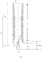
- Fig. 7
- shows a sectional view of an injector-ventury assembly according to an embodiment;
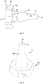
- Fig. 8
- shows a sectional view of an injector nozzle, a threaded nut and a gas supply pipe according to an embodiment; and
- Fig. 9
- shows a perspective view of an injector nozzle and a threaded nut according to an embodiment.
- In the Figures, like reference numerals designate like or functionally equivalent elements, unless otherwise indicated.
-
Fig. 1 schematically shows a top view of agas hob 1 according to an embodiment. Thegas hob 1 comprises atop sheet 2 and fourgas burners 3. Apan support structure 4, which may be a metal grid, metal arms or the like, is placed on thetop sheet 2. Thegas hob 1 may be configured as a domestic cooking appliance and may be, for example, part of a gas stove. -
Fig. 2 shows a schematic sectional view of a knowngas burner 3. The knowngas burner 3 comprises an injector-venturi assembly 5 including aninjector nozzle 6 and aventuri pipe 7. Thegas burner 3 further comprises aspreader 8 and acap 9, for example. - In operation,
fuel gas 31 is supplied to the knowngas burner 3 via a gas supply pipe (not shown inFig. 2 ). When an operator operates a knob or the like (not shown), a gas valve (not shown) is opened, andfuel gas 31 is supplied to theinjector nozzle 6. Theinjector nozzle 6 ejects thefuel gas 31 into theventuri pipe 7. By virtue of the venturi-effect, a suction is generated andprimary air 11 is pulled in through agap 10 between theinjector nozzle 6 and theventuri pipe 7. That is, theprimary air 11 stream is entrained in the ejectedfuel gas 31 stream. Inside theventuri pipe 7, which is an example of a mixing element, theprimary air 11 stream is mixed with thefuel gas 31 stream to obtain a stream of a flammable gas/air mixture. The flammable gas/air mixture leaves theventuri pipe 7 and travels, through achannel 12 formed between thespreader 8 and thecap 9, to a plurality ofgas ports 13 arranged circumferentially around thecap 9. At thegas ports 13, the flammable gas/air mixture is ignited to create aflame 14 for heating a pan, pot, wok or the like (not shown) placed on the pan support structure (4 inFig. 1 ). -
Fig. 3 shows a section of a known injector-venturi assembly 5 in greater detail. Theinjector nozzle 6 comprises agas inlet 15, agas outlet 16 and acircumferential wall 17. Thecircumferential wall 17 extends longitudinally from thegas inlet 15 to thegas outlet 16 and circumferentially around a longitudinal axis A of theinjector nozzle 6. It is noted that the horizontal direction inFig. 3 will be referred to as the longitudinal direction, whereas the vertical direction in the section shown inFig. 3 will be referred to as the radial direction. Thecircumferential wall 17 and, likewise, theinjector nozzle 6, each have a length H (longitudinal dimension between thegas inlet 15 and the gas outlet 16). The inner diameter of thegas outlet 16 is smaller than the inner diameter of thegas inlet 15. - The
venturi pipe 7 comprises aninlet port 18, anoutlet port 19 and acircumferential wall 20. It is noted that an inner diameter of a middle portion of thecircumferential wall 20 located longitudinally between theinlet port 18 and theoutlet port 19 is smaller than an inner diameter of theinlet port 18 and is also smaller than an inner diameter of theoutlet port 19. Thecircumferential wall 20 and, likewise, theventuri pipe 7, each have a length L (longitudinal dimension between theinlet port 18 and the outlet port 19). - The known
injector nozzle 6 is arranged such that thegas outlet 16 thereof is longitudinally adjacent to theinlet port 18 of theventuri pipe 7. An inner diameter of theinlet port 18 of theventuri pipe 7 is larger than an outer diameter of thegas outlet 16 of theinjector nozzle 6. Thus, aradial gap 10 is formed between thegas outlet 16 of theinjector nozzle 6 and theinlet port 18 of thenventuri pipe 7. Theradial gap 10 allowsprimary air 11 to be pulled in therethrough by a suction created by virtue of the venturi effect of theventuri pipe 7. - It is noted that features and configurations described for the known
injector nozzle 6 and the known injector-venturi assembly 5 also apply to theinjector nozzle 6 and the injector-venturi assembly 5 according to the various embodiments described hereinbelow, unless noted otherwise. -
Fig. 4 shows afuel gas stream 21 and aprimary air stream 22 forvarious injector nozzle 6 geometries. In particular,Fig. 4 a) shows a knowninjector nozzle 6, whileFig. 4 b) and c )show injector nozzles 6 according to respective embodiments. It is noted that inFig. 4 a) to c), the vertical direction is the longitudinal direction and the horizontal direction is the radial direction. - In the known
injector nozzle 6 shown inFig. 4 a) , neither theinner surface 23 nor theouter surface 24 of thecircumferential wall 17 have a polynomial shape. Accordingly, a velocity profile of thefuel gas stream 21 ejected from theoutlet port 16 of the knowninjector nozzle 6 ofFig. 4 a) is a parabolic profile. In particular, at a circumferential border of thefuel gas stream 21, which is a portion of thefuel gas stream 21 that is adjacent to theprimary air stream 22 to be entrained, a velocity of the fuel gas is low. - The
injector nozzle 6 according to an embodiment shown inFig. 4 b) differs from the knowninjector nozzle 6 shown inFig. 4 a) in that theinner surface 23 of thecircumferential wall 17 of theinjector nozzle 6 ofFig. 4 b) has a polynomial shape. That is, an inner diameter d in a radial direction of thecircumferential wall 17 varies along the longitudinal axis A in accordance with a polynomial function of a distance x from thegas inlet 15. It is noted thatFig. 4 b) shows the half diameter d/2. - This configuration has the effect shown in
Fig. 4 b) , i.e., a velocity profile of thefuel gas stream 21 ejected from thegas outlet 16 is a so-called "flat top profile", wherein the fuel gas velocity is substantially uniform across theentire gas outlet 16. More particularly, at a circumferential border of thefuel gas stream 21, which is a portion of thefuel gas stream 21 that is adjacent to theprimary air stream 22 to be entrained, a velocity is larger than in the comparative example shown inFig. 4a ). - The
injector nozzle 6 according to a further embodiment shown inFig. 4 c) differs from theinjector nozzle 6 ofFig. 4 b) in that, in theinjector nozzle 6 ofFig. 4c ), also anouter surface 24 of thecircumferential wall 17 has a polynomial shape. That is, also an outer diameter D in a radial direction of thecircumferential wall 17 varies along the longitudinal axis A in accordance with a polynomial function of a distance x from thegas inlet 15. Thecircumferential wall 17 may thus have a constant thickness along the longitudinal axis A. This configuration can further improve the mixing performance, as will be shown below. - In order to confirm the effects of the polynomial-shaped surfaces of the
circumferential wall 17, computer simulations have been carried out on a known injector-venturi system 5 (Fig. 3 ) configured according to a comparative example and on five injector-venturi systems 5 (Fig. 7 ) configured according to respective five working examples. -
Fig. 5 shows sectional views of a geometry of aninjector nozzle 6 of the comparative example and five geometries ofrespective injector nozzles 6 according to the five working examples. - Each of the
injector nozzles 6 shown inFig. 5 a) to f) have a first inner diameter at thegas outlet 16 of d1 = 1.71 mm, and a second inner diameter at thegas inlet 15 of d2 = 4.5 mm. - The
injector nozzle 6 of the comparative example shown inFig. 5 a) has a height H = 12,26 mm. - The
injector nozzle 6 of the first working example shown inFig. 5 b) has the same height H as thecomparative injector nozzle 6 shown inFig. 5 a) . It differs from the latter in that theinner surface 23 of thecircumferential wall 17 has a polynomial shape. - The
injector nozzle 6 of the second working example shown inFig. 5 c) differs from theinjector nozzle 6 of the first working example shown inFig. 5 b) in that also itsouter surface 24 has a polynomial shape. - The
injector nozzle 6 of the third working example shown inFig. 5 d) differs from theinjector nozzle 6 of the second working example shown inFig. 5 c) in that it has a reduced height h = 2/3 H = 8.17 mm. - The
injector nozzle 6 of the fourth working example shown inFig. 5 e) differs from theinjector nozzle 6 of the second working example shown inFig. 5 c) in that it has a reduced height h = 1/3 H = 4.09 mm. - The
injector nozzle 6 of the fifth working example shown inFig. 5 f) differs from theinjector nozzle 6 of the second working example shown inFig. 5 c) in that it has a greater height h = 4/3 H = 16.35 mm. -
Fig. 6 shows a graph ofpolynomial functions 25 describing the respectiveinner surface 23 of theinjector nozzles 6 of the various working examples. More specifically, a distance x measured in mm along the longitudinal axis A is plotted horizontally, and a distance y measured in mm along the radial axis is plotted vertically. - In the following, reference is made to
Fig. 5 and Fig. 6 . Thepolynomial function 251 describes the variation of the inner half diameter d/2 of theinjector nozzle 6 of the first and second working examples shown inFig. 5 b) and Fig. 5 c) along the longitudinal axisA. Polynomial function 252 describes the variation of the inner half diameter d/2 of theinjector nozzle 6 of the third working example shown inFig. 5 d) .Polynomial function 253 describes the variation of the inner half diameter d/2 of theinjector nozzle 6 of the fourth working example shown inFig. 5 e) .Polynomial function 254 describes the variation of the inner half diameter d/2 of theinjector nozzle 6 of the fifth working example shown inFig. 5f ). - Each of the
polynomial functions 25 is a sixth-order polynomial function and can be expressed by formula (I):
- Herein, x is a distance between the
gas inlet 15 and a radial cross section through theinjection nozzle 6, the distance x being measured along the longitudinal axis A. Further, "0,5 d(x)" is the inner half diameter d/2 of thecircumferential wall 17 measured in the radial cross section taken at the distance, or longitudinal position, x. - In order to determine the coefficients A, B, C, D, E, F, G for each of the working examples, the following boundary conditions were set:
- 1. d(x=0) shall be the inlet diameter of d2 = 4.5 mm.
- 2. d(x=h) shall be the outlet diameter of d1 = 1.71 mm, wherein h is the respective height (h = H, 2/3 H, 1/3 H or 4/3 H, with H = 12.26 mm, as outlined above for the various working examples).
- 3. The first derivative of d(x) for x shall be zero at x=0.
- 4. The first derivative of d(x) for x shall be zero at x=h.
- 5. The second derivative of d(x) for x shall be zero (there shall be an inflection point) at x = 0.6 h.
- 6. The half diameter at the inflection point shall be the average between the inlet diameter d2 and the outlet diameter d1, that is d(x = 0.6 h) = 0.5 (d1 + d2).
- By inserting each of the above six boundary conditions into formula (I) shown above, a linear equation system was obtained and solved for the coefficients A to G. The solutions obtained are shown in the following table (I).
Table (I) - Polynomial Coefficients 1st and 2nd examples Fig. 5 b), c ),polynomial function 2513d working example Fig. 5 d) polynomial function 2524th example Fig. 5 e) function 2535th example Fig. 5 f) function 254A -9.3436E-06 -1.0643E-04 -6.8115E-03 -1.6630E-02 B 2.6910E-04 2.0435E-03 6.5391E-02 6.3858E-05 C -2.0182E-03 -1.0217E-02 -1.6348E-01 -6.3858E-04 D -3.3610E-17 6.7220E-17 1.2100E-15 8.4026E-18 E 0.0000E+00 0.0000E+00 0.0000E+00 0.0000E+00 F 0.0000E+00 0.0000E+00 0.0000E+00 0.0000E+00 G 4.5000E+00 4.5000E+00 4.5000E+00 4.5000E+00 - It is noted that to facilitate illustration, in
Fig. 6 the half diameter d(x)/2 is plotted for each of thepolynomial functions Fig. 6 may also be understood as a schematic representation of a cross-sectional shape of a respective inner surface 23 (Figs. 5 ). - A total of five injector-venturi assemblies 5 (similar to the known injector-venturi assembly 5 (
Fig. 3 ) were obtained for simulation. For each of the simulated injector-venturi assemblies 5, the length of the venturi pipe 7 (Fig. 3 ) was set at L = 81.74 mm, and the height H of the known comparative reference injector nozzle 6 (Fig. 5 a) ) was set at H = 12.26 mm. - A first injector-venturi assembly (not shown) was created by replacing, in the injector-venturi assembly 5 (
Fig. 3 ), the known injector nozzle 6 (Fig. 3 ,5a )) with the injector nozzle 6 (Fig. 5 b) ) of the first working example. - A second injector-venturi assembly (not shown) was created by replacing, in the injector-venturi assembly 5 (
Fig. 3 ), the known injector nozzle 6 (Fig. 3 ,5a )) with the injector nozzle 6 (Fig. 5 c) ) of the second working example. - A third injector-venturi assembly (not shown) was created by replacing, in the injector-venturi assembly 5 (
Fig. 3 ), the known injector nozzle 6 (Fig. 3 ,5a )) with the injector nozzle 6 (Fig. 5 d) ) of the third working example. It is noted that theinjector nozzle 6 ofFig. 5 d) is shorter than the knowninjector nozzle 6 ofFig. 5 a) . Therefore, in the injector-venturi assembly 5 ofFig. 3 , theinjector nozzle 6 ofFig. 5 d) was arranged such that itsgas inlet 15 is at the same position as thegas inlet 15 of theinjector nozzle 6 ofFigs 3 ,5a ) that it replaces. That is, in addition to theradial gap 10 shown inFig. 3 , in the present working example, there is also a longitudinal gap of 1/3 H in the longitudinal direction between theventuri pipe 7 ofFig. 3 and theinjector nozzle 6 ofFig. 5 d) . - A fourth injector-venturi assembly (not shown) was created by replacing, in the third injector-venturi assembly, the injector nozzle 6 (
Fig. 5 d) ) of the third working example with the injector nozzle 6 (Fig. 5 e) ) of the fourth working example. Theinjector nozzle 6 ofFig. 5 e) is even shorter than theinjector nozzle 6 ofFig. 5 d) . Thus, the longitudinal gap between the venturi pipe 7 (Fig. 3 ) and the injector nozzle ofFig. 5 d) is even larger in the fourth injector-venturi assembly and amounts to 2/3 H. - Finally, a fifth injector-
venturi assembly 5 was created by replacing, in the injector-venturi assembly 5 (Fig. 3 ), the known injector nozzle 6 (Fig. 3 ,5a )) with the injector nozzle 6 (Fig. 5 f) ) of the fifth working example. A sectional view of the fifth injector-venturi assembly is shown inFig. 7 . It is noted that theinjector nozzle 6 ofFig. 5 f) ,7 is longer than the knowninjector nozzle 6 ofFig. 5 a) . Still, as shown inFig. 7 , theinjector nozzle 6 inFig. 7 is arranged such that itsgas inlet 15 is at the same position as thegas inlet 15 of theinjector nozzle 6 ofFig. 3 ,5a ) that it replaces. That is, theinjector nozzle 6 of the sixth working example is introduced into aninlet port 17 of theventuri pipe 7 such that a portion of theventuri pipe 7 including theinlet port 17 and a portion of theinjector nozzle 6 including thegas outlet 16 overlap. Thus, an overall length L+H of the fifth injector-venturi assembly 5 (Fig. 7 ) is unchanged and is the same as the overall length L+H of the known injector-venturi assembly 5 (Fig. 3 ). - For each of the injector/
venturi assemblies 5, a simulation was carried out based on the assumption thatfuel gas 31 is provided to thegas inlet 15 of theinjector nozzle 6 at a pressure of 20 mbar. The simulation results are shown in the following table (II):Table (II) - Simulation Results mair/mfuel increase Em / L Comparative example 9.31 reference case 1.00 Fig. 3 ,Fig. 5 a) 1st working example, 9.49 2.00 % 1.00 polynomial inner surface, Fig. 5 b) 2nd working example, 9.94 6.78 % 1.00 polynomial inner+outer surfaces, Fig. 5 c) 3rd working example 9.86 5.89 % 1.05 shortened length h=2/3 H, Fig. 5 d) (Em = L + 1/3 H) 4th working example 9.54 2.53 % 1.10 shortened length h=1/3 H, Fig. 5 e) (Em = L + 2/3 H) 5th working example, 10.05 8.00 % 0.95 large length h=4/3 H, overlap with venturi, Fig. 7 ,5f )(Em = L - 1/3 H) - Table II shows, for each of the working examples:
- i. The entrainment ratio mair/mfuel, wherein mair is the mass flow rate of the primary air stream and mfuel is the mass flow rate of the fuel gas stream.
- ii. The increase in the entrainment ratio versus the reference case of the comparative example.
- iii. The ratio of effective mixing distance Em to the total length L of the
venturi pipe 7. The effective mixing distance Em (Fig. 7 ) is the distance between thegas outlet 16 of theinjector nozzle 6 and theoutlet port 19 of theventuri pipe 7, i.e., a distance within which mixing of fuel gas and primary air is possible. - As can be seen in table (II), for each of the first to fifth working examples, the entrainment ratio is improved over the entrainment ratio of the comparative example. That is, an increased amount of primary air 11 (
Fig. 2 ) may be entrained in the fuel gas stream 21 (Fig. 4 ), combustion may be improved and emissions of pollutant and greenhouse gases may be reduced. - What is particular noteworthy is that, in working example 5, the injector nozzle 6 (
Fig. 5 f) ,7 ) is longer than the injector nozzle 6 (Fig. 3 ,5a )) of the comparative example and is partly inserted into theventuri pipe 7. This causes the effective mixing distance Em to be shorter than the total length L of the venturi pipe 7 (Fig. 7 ). Yet still, working example 5 achieves the best overall improvement of the entrainment ratio. - In other words, according to embodiments of the proposed solution, through use of a polynomial shaped
injector nozzle 6, a primary air/fuel gas entrainment rate may be improved. Further improvements of the entrainment rate may be achieved by either shortening the polynomial shapedinjector nozzle 6 and leaving a longitudinal gap between theinjector nozzle 6 and theventuri pipe 7. Conversely, further improvements may also be achieved by using a longer polynomial shapedinjector nozzle 6 that is partly introduced into theventuri pipe 7. In each of these embodiments, the entrainment rate may be improved while keeping an overall length L+H of the injector-venturi assembly 5 (Fig. 3 ,7 ) constant. That is, a space requirement under a top sheet (2 inFig. 1 ) of agas hob 1 is kept constant. - It is likewise contemplated that the
injector nozzle 6 ofFig. 5 f) may be inserted yet further into theventuri pipe 7, or that one of the shortenedinjector nozzle 6 ofFig. 5d) or Fig 5e ) may be arranged such that a smaller longitudinal gap or no longitudinal gap is present between the venturi pipe 7 (Fig. 3 ,7 ) and theinjector nozzle 6. In each of these contemplated embodiments, an overall length L+H of the injector-venturi assembly 5 (Fig. 7 ) may be reduced, thereby reducing a space requirement under the top sheet (2 inFig. 1 ) of the domestic cooking appliance, while still an entrainment rate that is higher or at least the same as the entrainment rate achieved in the comparative example. -
Fig. 8 shows a sectional view, andFig. 9 shows a perspective view, of afurther injector nozzle 6 of a further embodiment. Theinjector nozzle 6 of the present embodiment has a polynomial shapedouter surface 24 and a polynomial shapedinner surface 23, similar to the second to fifth working examples discussed above. - In the
injector nozzle 6 ofFig. 8 , at or near thegas inlet 15, thecircumferential wall 17 of theinjector nozzle 6 protrudes in a radial direction so as to form acircumferential flange portion 26. Theflange portion 26 is adapted to be flush with anouter face 30 of agas supply pipe 27. Thegas supply pipe 27 has anouter thread 28. A threadednut 29 having an inner thread (not shown) is placed over theinjector nozzle 6 and is screwed onto theouter thread 28 of thegas supply pipe 27 so as to fix theinjector nozzle 6 to thegas supply pipe 27. - By having the
flange portion 26, theinjector nozzle 6 of the present embodiment may be easily fixed to agas supply pipe 27 below a top sheet 2 (Fig. 1 ) of a domestic cooking appliance by means of screwing the threadednut 29 over theinjector nozzle 6 and onto theouter thread 28 of thegas supply pipe 27. - Although the present invention has been described in accordance with preferred embodiments, it is obvious for the person skilled in the art that modifications are possible in all embodiments.
- The numbers and dimensions discussed in connection with the working examples are mere examples and the present invention is not limited to these precise dimensions. For example, the inflection point does not need to be located precisely at a height of 0.6 H, but may also be located at a different suitable longitudinal location, preferably within a range of 0.5 H to 0.8 H.
- The
injector nozzles 6 and injector-venturi assemblies 5 shown and described above may be suitably implemented as forming part of a gas burner 3 (Fig. 2 ) of a gas hob 1 (Fig. 1 ). A domestic cooking appliance may be, for example, agas hob 1, and may comprise a number ofgas burners 3 each comprising an injector-venturi assembly 5 or aninjector nozzle 6 according to one of the embodiments as discussed in connection withFigures 5 to 9 . -
- 1
- gas hob
- 2
- top sheet
- 3
- gas burner
- 4
- pan support structure
- 5
- injector-venturi assembly
- 6
- injector nozzle
- 7
- venturi pipe
- 8
- spreader
- 9
- cap
- 10
- gap
- 11
- primary air
- 12
- channel
- 13
- gas port
- 14
- flame
- 15
- gas inlet
- 16
- gas outlet
- 17
- circumferential wall
- 18
- inlet port
- 19
- outlet port
- 20
- circumferential wall
- 21
- fuel gas stream
- 22
- primary air stream
- 23
- inner surface
- 24
- outer surface
- 25
- polynomial function
- 26
- flange portion
- 27
- gas pipe
- 28
- outer thread
- 29
- threaded nut
- 30
- outer face
- 31
- fuel gas
- 251-255
- respective polynomial function of the first to fifth working example
- A
- longitudinal axis
- d/2
- inner half diameter
- D/2
- outer half diameter
- Em
- effective mixing distance
- H
- height of known injector nozzle of comparative example
- L
- length of venturi pipe
Claims (13)
- A gas burner (3) for a gas hob (1), the gas burner (3) comprising a mixing element (7) for mixing a fuel gas (31) with primary air (11) and an injector nozzle (6) adapted to inject a stream (21) of the fuel gas (31) into the mixing element (7) such that a stream (22) of the primary air (11) is entrained in the stream (21) of the fuel gas (31), the injector nozzle (6) comprising a gas outlet (16) having a first inner diameter, a gas inlet (15) having a second inner diameter larger than the first inner diameter, and a circumferential wall (17) extending along a longitudinal axis (A) of the injector nozzle (6) from the gas inlet (15) to the gas outlet (16) and circumferentially around the longitudinal axis (A), wherein, in a radial cross section of the circumferential wall (17), an inner diameter (d) of the circumferential wall (17) varies along the longitudinal axis (A) in accordance with a polynomial function (25) of a distance (x) between the gas inlet (15) and the radial cross section measured along the longitudinal axis (A).
- The gas burner of claim 1, wherein the polynomial function (25) is a sixth-order polynomial function.
- The gas burner of one of claim 1 or 2, wherein the polynomial function (25) is defined such that a first derivative of the polynomial function (25) at the gas inlet (15) and a first derivative of the polynomial function (25) at the gas outlet (16) are zero.
- The gas burner of one of claims 1 - 3, wherein the polynomial function (25) is defined to have exactly one inflexion point between the gas inlet (15) and the gas outlet (16).
- The gas burner of one of claims 1 - 4, wherein the inflexion point is located at a distance (x) between 0.5 and 0.8 of a distance (h) between the gas inlet (15) and the gas outlet (16) measured along the longitudinal axis (A).
- The gas burner of one of claims 1 - 5, wherein, in the radial cross section of the circumferential wall (17), an outer diameter (D) of the circumferential wall (17) varies along the longitudinal axis (A) in accordance with a further polynomial function of a distance (x) between the gas inlet (15) and the radial cross section measured along the longitudinal axis (A).
- The gas burner of claim 6, wherein the further polynomial function is a sixth-order polynomial function.
- The gas burner of claim 6 or 7, wherein the further polynomial function is defined such that a thickness of the circumferential wall (17) is constant along the longitudinal axis (A) between the gas inlet (15) and the gas outlet (16).
- The gas burner of one of claims 1 - 8, wherein the mixing element comprises a venturi pipe (7), the injector nozzle (5) is adapted to inject the stream (21) of the fuel gas (31) into an inlet port (18) of the venturi pipe (7), and a gap (10) for entry of the primary air (11) is formed between the gas outlet (16) of the injector nozzle (6) and the inlet port (18) of the venturi pipe (7).
- The gas burner of claim 9, wherein the injector nozzle (6) is introduced, at least in part, into the inlet port (18) of the venturi pipe (7) such that a portion of the venturi pipe (7) including the inlet port (18) and a portion of the injector nozzle (6) including the gas outlet (16) overlap.
- The gas burner of one of claims 1 - 10, wherein, at the gas inlet (15), the circumferential wall (17) of the injector nozzle (6) protrudes in a radial direction so as to form a circumferential flange portion (26) for fixation of the injector nozzle (6).
- The gas burner of claim 11, wherein a threaded nut (29) is placed over the injector nozzle (6) and screwed onto an outer thread (28) of a gas supply pipe (27) so as to fix the circumferential flange portion (26) against the gas supply pipe (27).
- A gas hob (1) comprising at least one gas burner (3) according to any of claims 1 to 12.
Applications Claiming Priority (1)
| Application Number | Priority Date | Filing Date | Title |
|---|---|---|---|
| ES201930069A ES2776748A1 (en) | 2019-01-30 | 2019-01-30 | GAS BURNER FOR A GAS COUNTERTOP (Machine-translation by Google Translate, not legally binding) |
Publications (2)
| Publication Number | Publication Date |
|---|---|
| EP3690314A1 true EP3690314A1 (en) | 2020-08-05 |
| EP3690314B1 EP3690314B1 (en) | 2021-09-01 |
Family
ID=69172679
Family Applications (1)
| Application Number | Title | Priority Date | Filing Date |
|---|---|---|---|
| EP20151949.3A Active EP3690314B1 (en) | 2019-01-30 | 2020-01-15 | Gas burner for a gas hob |
Country Status (2)
| Country | Link |
|---|---|
| EP (1) | EP3690314B1 (en) |
| ES (1) | ES2776748A1 (en) |
Citations (4)
| Publication number | Priority date | Publication date | Assignee | Title |
|---|---|---|---|---|
| US5332161A (en) * | 1992-11-30 | 1994-07-26 | Manasco, Inc. | Burner nozzle assembly |
| WO2016124641A1 (en) * | 2015-02-04 | 2016-08-11 | Bosch Termotecnologia S.A. | Gas distributor device for an atmospheric gas burner |
| WO2017208095A1 (en) * | 2016-06-03 | 2017-12-07 | BSH Hausgeräte GmbH | Gas burner and domestic cooking appliance |
| KR20180031293A (en) * | 2016-09-19 | 2018-03-28 | 엘지전자 주식회사 | Burner and cooking appliance therewith |
Family Cites Families (4)
| Publication number | Priority date | Publication date | Assignee | Title |
|---|---|---|---|---|
| CN103185339B (en) * | 2011-12-28 | 2016-08-03 | 株式会社能率 | Rich-lean combustion burner and burner |
| US10107494B2 (en) * | 2014-04-22 | 2018-10-23 | Universal City Studios Llc | System and method for generating flame effect |
| US11246451B2 (en) * | 2015-10-12 | 2022-02-15 | Weber-Stephen Products Llc | Burner tube for gas grill |
| JP6634909B2 (en) * | 2016-03-18 | 2020-01-22 | 三浦工業株式会社 | Venturi nozzle and fuel supply device provided with the venturi nozzle |
-
2019
- 2019-01-30 ES ES201930069A patent/ES2776748A1/en not_active Withdrawn
-
2020
- 2020-01-15 EP EP20151949.3A patent/EP3690314B1/en active Active
Patent Citations (4)
| Publication number | Priority date | Publication date | Assignee | Title |
|---|---|---|---|---|
| US5332161A (en) * | 1992-11-30 | 1994-07-26 | Manasco, Inc. | Burner nozzle assembly |
| WO2016124641A1 (en) * | 2015-02-04 | 2016-08-11 | Bosch Termotecnologia S.A. | Gas distributor device for an atmospheric gas burner |
| WO2017208095A1 (en) * | 2016-06-03 | 2017-12-07 | BSH Hausgeräte GmbH | Gas burner and domestic cooking appliance |
| KR20180031293A (en) * | 2016-09-19 | 2018-03-28 | 엘지전자 주식회사 | Burner and cooking appliance therewith |
Also Published As
| Publication number | Publication date |
|---|---|
| EP3690314B1 (en) | 2021-09-01 |
| ES2776748A1 (en) | 2020-07-31 |
Similar Documents
| Publication | Publication Date | Title |
|---|---|---|
| CN102439360B (en) | Gas furnace | |
| FI68898B (en) | BRAENNARE FOER MONTERING I VAERMNINGS- OCH AONGPANNA | |
| KR102564755B1 (en) | The inlet assembly and how it works | |
| US20150034070A1 (en) | Gas burner for a cooktop | |
| EP4425048B1 (en) | Energy-efficient upside-entrainment burning system | |
| CN206247328U (en) | A kind of burner for gas kitchen ranges | |
| CN103742915B (en) | A kind of multi-cavity gas-air mixing arrangement | |
| JP2016536553A (en) | Rich lean combustion system | |
| CN110836411A (en) | Heat shield for stove and gas stove with heat shield | |
| EP3690314B1 (en) | Gas burner for a gas hob | |
| US20180135862A1 (en) | Main top of a cooktop appliance | |
| CN111735051A (en) | Burners and gas cooktops | |
| CN111735049A (en) | Burners and gas cooktops | |
| US20230349549A1 (en) | Burner and applications thereof | |
| CN221351286U (en) | An experimental device for studying thermoacoustic oscillations of hydrogen-rich gas combustion | |
| CN111609399A (en) | Burners and gas stoves | |
| KR102824372B1 (en) | Household cooking stove for combustion of LPG fuel with high thermal efficiency | |
| US20250383082A2 (en) | Burner device | |
| CN205351311U (en) | Combustor chassis and combustor | |
| CN1742181B (en) | gas stove | |
| CN205782924U (en) | A kind of end, fills wide flat attached wall flame low NOX gas burner | |
| CN214598275U (en) | Ammonia injection device | |
| US6979191B1 (en) | Combustion apparatus and method for radiating wall heating system | |
| CN211176777U (en) | Combustor and gas heater | |
| TW201944000A (en) | Wind-resistant outdoor stove combustion device |
Legal Events
| Date | Code | Title | Description |
|---|---|---|---|
| PUAI | Public reference made under article 153(3) epc to a published international application that has entered the european phase |
Free format text: ORIGINAL CODE: 0009012 |
|
| STAA | Information on the status of an ep patent application or granted ep patent |
Free format text: STATUS: THE APPLICATION HAS BEEN PUBLISHED |
|
| AK | Designated contracting states |
Kind code of ref document: A1 Designated state(s): AL AT BE BG CH CY CZ DE DK EE ES FI FR GB GR HR HU IE IS IT LI LT LU LV MC MK MT NL NO PL PT RO RS SE SI SK SM TR |
|
| AX | Request for extension of the european patent |
Extension state: BA ME |
|
| STAA | Information on the status of an ep patent application or granted ep patent |
Free format text: STATUS: REQUEST FOR EXAMINATION WAS MADE |
|
| 17P | Request for examination filed |
Effective date: 20210205 |
|
| RBV | Designated contracting states (corrected) |
Designated state(s): AL AT BE BG CH CY CZ DE DK EE ES FI FR GB GR HR HU IE IS IT LI LT LU LV MC MK MT NL NO PL PT RO RS SE SI SK SM TR |
|
| GRAP | Despatch of communication of intention to grant a patent |
Free format text: ORIGINAL CODE: EPIDOSNIGR1 |
|
| STAA | Information on the status of an ep patent application or granted ep patent |
Free format text: STATUS: GRANT OF PATENT IS INTENDED |
|
| INTG | Intention to grant announced |
Effective date: 20210421 |
|
| GRAS | Grant fee paid |
Free format text: ORIGINAL CODE: EPIDOSNIGR3 |
|
| GRAA | (expected) grant |
Free format text: ORIGINAL CODE: 0009210 |
|
| STAA | Information on the status of an ep patent application or granted ep patent |
Free format text: STATUS: THE PATENT HAS BEEN GRANTED |
|
| AK | Designated contracting states |
Kind code of ref document: B1 Designated state(s): AL AT BE BG CH CY CZ DE DK EE ES FI FR GB GR HR HU IE IS IT LI LT LU LV MC MK MT NL NO PL PT RO RS SE SI SK SM TR |
|
| REG | Reference to a national code |
Ref country code: GB Ref legal event code: FG4D |
|
| REG | Reference to a national code |
Ref country code: CH Ref legal event code: EP Ref country code: AT Ref legal event code: REF Ref document number: 1426608 Country of ref document: AT Kind code of ref document: T Effective date: 20210915 |
|
| REG | Reference to a national code |
Ref country code: DE Ref legal event code: R096 Ref document number: 602020000451 Country of ref document: DE |
|
| REG | Reference to a national code |
Ref country code: IE Ref legal event code: FG4D |
|
| REG | Reference to a national code |
Ref country code: LT Ref legal event code: MG9D |
|
| REG | Reference to a national code |
Ref country code: NL Ref legal event code: MP Effective date: 20210901 |
|
| PG25 | Lapsed in a contracting state [announced via postgrant information from national office to epo] |
Ref country code: ES Free format text: LAPSE BECAUSE OF FAILURE TO SUBMIT A TRANSLATION OF THE DESCRIPTION OR TO PAY THE FEE WITHIN THE PRESCRIBED TIME-LIMIT Effective date: 20210901 Ref country code: SE Free format text: LAPSE BECAUSE OF FAILURE TO SUBMIT A TRANSLATION OF THE DESCRIPTION OR TO PAY THE FEE WITHIN THE PRESCRIBED TIME-LIMIT Effective date: 20210901 Ref country code: RS Free format text: LAPSE BECAUSE OF FAILURE TO SUBMIT A TRANSLATION OF THE DESCRIPTION OR TO PAY THE FEE WITHIN THE PRESCRIBED TIME-LIMIT Effective date: 20210901 Ref country code: BG Free format text: LAPSE BECAUSE OF FAILURE TO SUBMIT A TRANSLATION OF THE DESCRIPTION OR TO PAY THE FEE WITHIN THE PRESCRIBED TIME-LIMIT Effective date: 20211201 Ref country code: LT Free format text: LAPSE BECAUSE OF FAILURE TO SUBMIT A TRANSLATION OF THE DESCRIPTION OR TO PAY THE FEE WITHIN THE PRESCRIBED TIME-LIMIT Effective date: 20210901 Ref country code: NO Free format text: LAPSE BECAUSE OF FAILURE TO SUBMIT A TRANSLATION OF THE DESCRIPTION OR TO PAY THE FEE WITHIN THE PRESCRIBED TIME-LIMIT Effective date: 20211201 Ref country code: FI Free format text: LAPSE BECAUSE OF FAILURE TO SUBMIT A TRANSLATION OF THE DESCRIPTION OR TO PAY THE FEE WITHIN THE PRESCRIBED TIME-LIMIT Effective date: 20210901 Ref country code: HR Free format text: LAPSE BECAUSE OF FAILURE TO SUBMIT A TRANSLATION OF THE DESCRIPTION OR TO PAY THE FEE WITHIN THE PRESCRIBED TIME-LIMIT Effective date: 20210901 |
|
| REG | Reference to a national code |
Ref country code: AT Ref legal event code: MK05 Ref document number: 1426608 Country of ref document: AT Kind code of ref document: T Effective date: 20210901 |
|
| PG25 | Lapsed in a contracting state [announced via postgrant information from national office to epo] |
Ref country code: PL Free format text: LAPSE BECAUSE OF FAILURE TO SUBMIT A TRANSLATION OF THE DESCRIPTION OR TO PAY THE FEE WITHIN THE PRESCRIBED TIME-LIMIT Effective date: 20210901 Ref country code: LV Free format text: LAPSE BECAUSE OF FAILURE TO SUBMIT A TRANSLATION OF THE DESCRIPTION OR TO PAY THE FEE WITHIN THE PRESCRIBED TIME-LIMIT Effective date: 20210901 Ref country code: GR Free format text: LAPSE BECAUSE OF FAILURE TO SUBMIT A TRANSLATION OF THE DESCRIPTION OR TO PAY THE FEE WITHIN THE PRESCRIBED TIME-LIMIT Effective date: 20211202 |
|
| PG25 | Lapsed in a contracting state [announced via postgrant information from national office to epo] |
Ref country code: AT Free format text: LAPSE BECAUSE OF FAILURE TO SUBMIT A TRANSLATION OF THE DESCRIPTION OR TO PAY THE FEE WITHIN THE PRESCRIBED TIME-LIMIT Effective date: 20210901 |
|
| PG25 | Lapsed in a contracting state [announced via postgrant information from national office to epo] |
Ref country code: IS Free format text: LAPSE BECAUSE OF FAILURE TO SUBMIT A TRANSLATION OF THE DESCRIPTION OR TO PAY THE FEE WITHIN THE PRESCRIBED TIME-LIMIT Effective date: 20220101 Ref country code: SM Free format text: LAPSE BECAUSE OF FAILURE TO SUBMIT A TRANSLATION OF THE DESCRIPTION OR TO PAY THE FEE WITHIN THE PRESCRIBED TIME-LIMIT Effective date: 20210901 Ref country code: SK Free format text: LAPSE BECAUSE OF FAILURE TO SUBMIT A TRANSLATION OF THE DESCRIPTION OR TO PAY THE FEE WITHIN THE PRESCRIBED TIME-LIMIT Effective date: 20210901 Ref country code: RO Free format text: LAPSE BECAUSE OF FAILURE TO SUBMIT A TRANSLATION OF THE DESCRIPTION OR TO PAY THE FEE WITHIN THE PRESCRIBED TIME-LIMIT Effective date: 20210901 Ref country code: PT Free format text: LAPSE BECAUSE OF FAILURE TO SUBMIT A TRANSLATION OF THE DESCRIPTION OR TO PAY THE FEE WITHIN THE PRESCRIBED TIME-LIMIT Effective date: 20220103 Ref country code: NL Free format text: LAPSE BECAUSE OF FAILURE TO SUBMIT A TRANSLATION OF THE DESCRIPTION OR TO PAY THE FEE WITHIN THE PRESCRIBED TIME-LIMIT Effective date: 20210901 Ref country code: EE Free format text: LAPSE BECAUSE OF FAILURE TO SUBMIT A TRANSLATION OF THE DESCRIPTION OR TO PAY THE FEE WITHIN THE PRESCRIBED TIME-LIMIT Effective date: 20210901 Ref country code: CZ Free format text: LAPSE BECAUSE OF FAILURE TO SUBMIT A TRANSLATION OF THE DESCRIPTION OR TO PAY THE FEE WITHIN THE PRESCRIBED TIME-LIMIT Effective date: 20210901 Ref country code: AL Free format text: LAPSE BECAUSE OF FAILURE TO SUBMIT A TRANSLATION OF THE DESCRIPTION OR TO PAY THE FEE WITHIN THE PRESCRIBED TIME-LIMIT Effective date: 20210901 |
|
| REG | Reference to a national code |
Ref country code: DE Ref legal event code: R097 Ref document number: 602020000451 Country of ref document: DE |
|
| PLBE | No opposition filed within time limit |
Free format text: ORIGINAL CODE: 0009261 |
|
| STAA | Information on the status of an ep patent application or granted ep patent |
Free format text: STATUS: NO OPPOSITION FILED WITHIN TIME LIMIT |
|
| PG25 | Lapsed in a contracting state [announced via postgrant information from national office to epo] |
Ref country code: DK Free format text: LAPSE BECAUSE OF FAILURE TO SUBMIT A TRANSLATION OF THE DESCRIPTION OR TO PAY THE FEE WITHIN THE PRESCRIBED TIME-LIMIT Effective date: 20210901 |
|
| REG | Reference to a national code |
Ref country code: DE Ref legal event code: R119 Ref document number: 602020000451 Country of ref document: DE |
|
| 26N | No opposition filed |
Effective date: 20220602 |
|
| PG25 | Lapsed in a contracting state [announced via postgrant information from national office to epo] |
Ref country code: SI Free format text: LAPSE BECAUSE OF FAILURE TO SUBMIT A TRANSLATION OF THE DESCRIPTION OR TO PAY THE FEE WITHIN THE PRESCRIBED TIME-LIMIT Effective date: 20210901 Ref country code: MC Free format text: LAPSE BECAUSE OF FAILURE TO SUBMIT A TRANSLATION OF THE DESCRIPTION OR TO PAY THE FEE WITHIN THE PRESCRIBED TIME-LIMIT Effective date: 20210901 |
|
| REG | Reference to a national code |
Ref country code: BE Ref legal event code: MM Effective date: 20220131 |
|
| PG25 | Lapsed in a contracting state [announced via postgrant information from national office to epo] |
Ref country code: LU Free format text: LAPSE BECAUSE OF NON-PAYMENT OF DUE FEES Effective date: 20220115 Ref country code: DE Free format text: LAPSE BECAUSE OF NON-PAYMENT OF DUE FEES Effective date: 20220802 |
|
| PG25 | Lapsed in a contracting state [announced via postgrant information from national office to epo] |
Ref country code: FR Free format text: LAPSE BECAUSE OF NON-PAYMENT OF DUE FEES Effective date: 20220131 Ref country code: BE Free format text: LAPSE BECAUSE OF NON-PAYMENT OF DUE FEES Effective date: 20220131 |
|
| PG25 | Lapsed in a contracting state [announced via postgrant information from national office to epo] |
Ref country code: IE Free format text: LAPSE BECAUSE OF NON-PAYMENT OF DUE FEES Effective date: 20220115 |
|
| REG | Reference to a national code |
Ref country code: CH Ref legal event code: PL |
|
| PG25 | Lapsed in a contracting state [announced via postgrant information from national office to epo] |
Ref country code: LI Free format text: LAPSE BECAUSE OF NON-PAYMENT OF DUE FEES Effective date: 20230131 Ref country code: CH Free format text: LAPSE BECAUSE OF NON-PAYMENT OF DUE FEES Effective date: 20230131 |
|
| PG25 | Lapsed in a contracting state [announced via postgrant information from national office to epo] |
Ref country code: MK Free format text: LAPSE BECAUSE OF FAILURE TO SUBMIT A TRANSLATION OF THE DESCRIPTION OR TO PAY THE FEE WITHIN THE PRESCRIBED TIME-LIMIT Effective date: 20210901 Ref country code: CY Free format text: LAPSE BECAUSE OF FAILURE TO SUBMIT A TRANSLATION OF THE DESCRIPTION OR TO PAY THE FEE WITHIN THE PRESCRIBED TIME-LIMIT Effective date: 20210901 |
|
| PG25 | Lapsed in a contracting state [announced via postgrant information from national office to epo] |
Ref country code: HU Free format text: LAPSE BECAUSE OF FAILURE TO SUBMIT A TRANSLATION OF THE DESCRIPTION OR TO PAY THE FEE WITHIN THE PRESCRIBED TIME-LIMIT; INVALID AB INITIO Effective date: 20200115 |
|
| GBPC | Gb: european patent ceased through non-payment of renewal fee |
Effective date: 20240115 |
|
| PG25 | Lapsed in a contracting state [announced via postgrant information from national office to epo] |
Ref country code: MT Free format text: LAPSE BECAUSE OF FAILURE TO SUBMIT A TRANSLATION OF THE DESCRIPTION OR TO PAY THE FEE WITHIN THE PRESCRIBED TIME-LIMIT Effective date: 20210901 |
|
| PG25 | Lapsed in a contracting state [announced via postgrant information from national office to epo] |
Ref country code: GB Free format text: LAPSE BECAUSE OF NON-PAYMENT OF DUE FEES Effective date: 20240115 |
|
| PG25 | Lapsed in a contracting state [announced via postgrant information from national office to epo] |
Ref country code: GB Free format text: LAPSE BECAUSE OF NON-PAYMENT OF DUE FEES Effective date: 20240115 |
|
| PGFP | Annual fee paid to national office [announced via postgrant information from national office to epo] |
Ref country code: IT Payment date: 20260130 Year of fee payment: 7 |
|
| PGFP | Annual fee paid to national office [announced via postgrant information from national office to epo] |
Ref country code: TR Payment date: 20260114 Year of fee payment: 7 |