EP3690311A1 - Lighting device - Google Patents
Lighting device Download PDFInfo
- Publication number
- EP3690311A1 EP3690311A1 EP18862283.1A EP18862283A EP3690311A1 EP 3690311 A1 EP3690311 A1 EP 3690311A1 EP 18862283 A EP18862283 A EP 18862283A EP 3690311 A1 EP3690311 A1 EP 3690311A1
- Authority
- EP
- European Patent Office
- Prior art keywords
- light
- lighting device
- transmissive portion
- lens
- incident
- Prior art date
- Legal status (The legal status is an assumption and is not a legal conclusion. Google has not performed a legal analysis and makes no representation as to the accuracy of the status listed.)
- Granted
Links
Images



Classifications
-
- F—MECHANICAL ENGINEERING; LIGHTING; HEATING; WEAPONS; BLASTING
- F21—LIGHTING
- F21V—FUNCTIONAL FEATURES OR DETAILS OF LIGHTING DEVICES OR SYSTEMS THEREOF; STRUCTURAL COMBINATIONS OF LIGHTING DEVICES WITH OTHER ARTICLES, NOT OTHERWISE PROVIDED FOR
- F21V5/00—Refractors for light sources
- F21V5/007—Array of lenses or refractors for a cluster of light sources, e.g. for arrangement of multiple light sources in one plane
-
- F—MECHANICAL ENGINEERING; LIGHTING; HEATING; WEAPONS; BLASTING
- F21—LIGHTING
- F21S—NON-PORTABLE LIGHTING DEVICES; SYSTEMS THEREOF; VEHICLE LIGHTING DEVICES SPECIALLY ADAPTED FOR VEHICLE EXTERIORS
- F21S8/00—Lighting devices intended for fixed installation
- F21S8/08—Lighting devices intended for fixed installation with a standard
- F21S8/085—Lighting devices intended for fixed installation with a standard of high-built type, e.g. street light
-
- F—MECHANICAL ENGINEERING; LIGHTING; HEATING; WEAPONS; BLASTING
- F21—LIGHTING
- F21S—NON-PORTABLE LIGHTING DEVICES; SYSTEMS THEREOF; VEHICLE LIGHTING DEVICES SPECIALLY ADAPTED FOR VEHICLE EXTERIORS
- F21S8/00—Lighting devices intended for fixed installation
- F21S8/08—Lighting devices intended for fixed installation with a standard
- F21S8/085—Lighting devices intended for fixed installation with a standard of high-built type, e.g. street light
- F21S8/086—Lighting devices intended for fixed installation with a standard of high-built type, e.g. street light with lighting device attached sideways of the standard, e.g. for roads and highways
-
- F—MECHANICAL ENGINEERING; LIGHTING; HEATING; WEAPONS; BLASTING
- F21—LIGHTING
- F21V—FUNCTIONAL FEATURES OR DETAILS OF LIGHTING DEVICES OR SYSTEMS THEREOF; STRUCTURAL COMBINATIONS OF LIGHTING DEVICES WITH OTHER ARTICLES, NOT OTHERWISE PROVIDED FOR
- F21V3/00—Globes; Bowls; Cover glasses
- F21V3/02—Globes; Bowls; Cover glasses characterised by the shape
-
- F—MECHANICAL ENGINEERING; LIGHTING; HEATING; WEAPONS; BLASTING
- F21—LIGHTING
- F21V—FUNCTIONAL FEATURES OR DETAILS OF LIGHTING DEVICES OR SYSTEMS THEREOF; STRUCTURAL COMBINATIONS OF LIGHTING DEVICES WITH OTHER ARTICLES, NOT OTHERWISE PROVIDED FOR
- F21V3/00—Globes; Bowls; Cover glasses
- F21V3/04—Globes; Bowls; Cover glasses characterised by materials, surface treatments or coatings
- F21V3/10—Globes; Bowls; Cover glasses characterised by materials, surface treatments or coatings characterised by coatings
-
- F—MECHANICAL ENGINEERING; LIGHTING; HEATING; WEAPONS; BLASTING
- F21—LIGHTING
- F21V—FUNCTIONAL FEATURES OR DETAILS OF LIGHTING DEVICES OR SYSTEMS THEREOF; STRUCTURAL COMBINATIONS OF LIGHTING DEVICES WITH OTHER ARTICLES, NOT OTHERWISE PROVIDED FOR
- F21V5/00—Refractors for light sources
- F21V5/04—Refractors for light sources of lens shape
-
- F—MECHANICAL ENGINEERING; LIGHTING; HEATING; WEAPONS; BLASTING
- F21—LIGHTING
- F21V—FUNCTIONAL FEATURES OR DETAILS OF LIGHTING DEVICES OR SYSTEMS THEREOF; STRUCTURAL COMBINATIONS OF LIGHTING DEVICES WITH OTHER ARTICLES, NOT OTHERWISE PROVIDED FOR
- F21V5/00—Refractors for light sources
- F21V5/08—Refractors for light sources producing an asymmetric light distribution
-
- G—PHYSICS
- G02—OPTICS
- G02B—OPTICAL ELEMENTS, SYSTEMS OR APPARATUS
- G02B19/00—Condensers, e.g. light collectors or similar non-imaging optics
- G02B19/0004—Condensers, e.g. light collectors or similar non-imaging optics characterised by the optical means employed
- G02B19/0009—Condensers, e.g. light collectors or similar non-imaging optics characterised by the optical means employed having refractive surfaces only
- G02B19/0014—Condensers, e.g. light collectors or similar non-imaging optics characterised by the optical means employed having refractive surfaces only at least one surface having optical power
-
- G—PHYSICS
- G02—OPTICS
- G02B—OPTICAL ELEMENTS, SYSTEMS OR APPARATUS
- G02B19/00—Condensers, e.g. light collectors or similar non-imaging optics
- G02B19/0033—Condensers, e.g. light collectors or similar non-imaging optics characterised by the use
- G02B19/0047—Condensers, e.g. light collectors or similar non-imaging optics characterised by the use for use with a light source
- G02B19/0061—Condensers, e.g. light collectors or similar non-imaging optics characterised by the use for use with a light source the light source comprising a LED
-
- G—PHYSICS
- G02—OPTICS
- G02B—OPTICAL ELEMENTS, SYSTEMS OR APPARATUS
- G02B27/00—Optical systems or apparatus not provided for by any of the groups G02B1/00 - G02B26/00, G02B30/00
- G02B27/09—Beam shaping, e.g. changing the cross-sectional area, not otherwise provided for
- G02B27/0938—Using specific optical elements
- G02B27/095—Refractive optical elements
- G02B27/0955—Lenses
-
- F—MECHANICAL ENGINEERING; LIGHTING; HEATING; WEAPONS; BLASTING
- F21—LIGHTING
- F21V—FUNCTIONAL FEATURES OR DETAILS OF LIGHTING DEVICES OR SYSTEMS THEREOF; STRUCTURAL COMBINATIONS OF LIGHTING DEVICES WITH OTHER ARTICLES, NOT OTHERWISE PROVIDED FOR
- F21V29/00—Protecting lighting devices from thermal damage; Cooling or heating arrangements specially adapted for lighting devices or systems
- F21V29/50—Cooling arrangements
- F21V29/70—Cooling arrangements characterised by passive heat-dissipating elements, e.g. heat-sinks
-
- F—MECHANICAL ENGINEERING; LIGHTING; HEATING; WEAPONS; BLASTING
- F21—LIGHTING
- F21W—INDEXING SCHEME ASSOCIATED WITH SUBCLASSES F21K, F21L, F21S and F21V, RELATING TO USES OR APPLICATIONS OF LIGHTING DEVICES OR SYSTEMS
- F21W2131/00—Use or application of lighting devices or systems not provided for in codes F21W2102/00-F21W2121/00
- F21W2131/10—Outdoor lighting
- F21W2131/103—Outdoor lighting of streets or roads
-
- F—MECHANICAL ENGINEERING; LIGHTING; HEATING; WEAPONS; BLASTING
- F21—LIGHTING
- F21Y—INDEXING SCHEME ASSOCIATED WITH SUBCLASSES F21K, F21L, F21S and F21V, RELATING TO THE FORM OR THE KIND OF THE LIGHT SOURCES OR OF THE COLOUR OF THE LIGHT EMITTED
- F21Y2105/00—Planar light sources
- F21Y2105/10—Planar light sources comprising a two-dimensional [2D] array of point-like light-generating elements
-
- F—MECHANICAL ENGINEERING; LIGHTING; HEATING; WEAPONS; BLASTING
- F21—LIGHTING
- F21Y—INDEXING SCHEME ASSOCIATED WITH SUBCLASSES F21K, F21L, F21S and F21V, RELATING TO THE FORM OR THE KIND OF THE LIGHT SOURCES OR OF THE COLOUR OF THE LIGHT EMITTED
- F21Y2105/00—Planar light sources
- F21Y2105/10—Planar light sources comprising a two-dimensional [2D] array of point-like light-generating elements
- F21Y2105/14—Planar light sources comprising a two-dimensional [2D] array of point-like light-generating elements characterised by the overall shape of the two-dimensional [2D] array
- F21Y2105/16—Planar light sources comprising a two-dimensional [2D] array of point-like light-generating elements characterised by the overall shape of the two-dimensional [2D] array square or rectangular, e.g. for light panels
-
- F—MECHANICAL ENGINEERING; LIGHTING; HEATING; WEAPONS; BLASTING
- F21—LIGHTING
- F21Y—INDEXING SCHEME ASSOCIATED WITH SUBCLASSES F21K, F21L, F21S and F21V, RELATING TO THE FORM OR THE KIND OF THE LIGHT SOURCES OR OF THE COLOUR OF THE LIGHT EMITTED
- F21Y2115/00—Light-generating elements of semiconductor light sources
- F21Y2115/10—Light-emitting diodes [LED]
Definitions
- the present invention relates to a lighting field, and more particularly, to a lighting device.
- An existing lighting device generally comprises several basic components, such as a light body, a light source module and a front cover; and the front cover is transparent. If an incident angle of light incident on the front cover is larger than a certain value, a certain proportion of the light is reflected by the front cover. See Table 1 below, taking parallel light incident on a flat glass front cover as an example, statistics of reflectance at different incident angles are provided. Table 1 Incident angle Reflectance Incident angle of 0 ° (vertical incidence) 8% Incident angle of 15 ° 8% Incident angle of 30 ° 9% Incident angle of 45 ° 10% Incident angle of 60 ° 17% Incident angle of 65 ° 22% Incident angle of 70 ° 30% Incident angle of 75 ° 41%
- An object of the present invention is to solve the above-described problems and provide a lighting device with higher light distribution efficiency.
- the present invention provides a lighting device, comprising a light body, a light source module mounted in the light body, and a light transmissive portion covering the light source module, in which, the light source module includes a plurality of lenses and a light emitting unit accommodated in the lens, light emitted by the light emitting unit is emitted from the light transmissive portion after being distributed by the lens, the light transmissive portion is arc-shaped, and an incident angle corresponding to incident light at any point of the light transmissive portion is smaller than 45 °.
- a length direction of the lens is a longitudinal direction
- a width direction of the lens is a lateral direction
- a central cross-sectional profile of the lens in the longitudinal direction and a central cross-sectional profile of the lens in the lateral direction are different from each other.
- the central cross-sectional profile of the lens in the longitudinal direction is a first profile
- the first profile is an axisymmetric pattern
- the first profile includes a first light incident surface and a first light emission surface.
- a curvature of the first light incident surface is greater than a curvature of the first light emission surface.
- the first light incident surface is a semi-ellipsoid
- the first light emission surface is an axisymmetric curved surface.
- the central cross-sectional profile of the lens in the lateral direction is a second profile, an outer surface and an inner surface of the second profile are both axisymmetric patterns, and a symmetry axis of the outer surface of the second profile and a symmetry axis of the inner surface of the second profile are parallel to each other.
- an angle corresponding to maximum intensity of light distributed by the lens is between 70° and 80°, and an incident angle of light corresponding to the maximum intensity in all light that is incident on the light transmissive portion is between 8° and 45°.
- a height of the light transmissive portion is 1/6.3 to 1/2 of a length of the light transmissive portion.
- the light transmissive portion is made of glass or plastic.
- the lighting device further comprises a light-emitting component
- the light-emitting component includes a light source board and a plurality of the light emitting units provided on the light source board, and one of the lenses corresponds to one of the light emitting units, or corresponds to several ones of the light emitting units.
- light transmittance of the light transmissive portion is greater than 90%.
- the lighting device is a street lamp.
- the street lamp further includes a driving power supply component accommodated in the light body, and the driving power supply component is electrically connected with the light source module.
- the street lamp further includes a front cover connected with the light body, and the front cover includes a coated portion and the light transmissive portion.
- the street lamp further includes a lamp pole, and the light body is mounted on the lamp pole.
- the light emitting units and the lens units are all arranged in an array.
- the lighting device further comprises a reflector provided in the light body, and the reflector is provided on a periphery of the light source module.
- the incident angle corresponding to the incident light on the light transmissive portion is limited within 45 °, which, thus, reduces the reflectance of the light transmissive portion to the incident light, so that a smaller light distribution change occurs during the light is emitted through the light transmissive portion, and improves light distribution efficiency of the lighting device.
- Embodiment 1 of the present invention provides a lighting device 100, comprising a light body 1, a light source module mounted in the light body 1, and a front cover 4 covering the light source module, in which, the light source module includes a light-emitting component 2 and a plurality of lenses 3 that distribute light from the light-emitting component 2, and light emitted from the lens 3 is emitted through the front cover 4.
- the lighting device 100 provided by the embodiment of the present invention for example is applied as a street lamp; a heat radiator 5, a reflector 6, and a driving power supply component (not shown) are further provided in the light body 1; and a cushion ring 7 is further provided between the light body 1 and the front cover 4.
- the light body 1 is formed with an accommodating space; and the light-emitting component 2, the lens 3, the heat radiator 5 and the reflector 6 are all accommodated in the accommodating space, in which, the heat radiator 5 is provided below the light-emitting component 2, and the reflector 6 is provided on a periphery of the light source module.
- the reflector 6 causes diffuse reflection; and because the light-emitting component 2 according to this embodiment sinks a bit, in order to further improve light-emitting efficiency of the light source module, the reflector 6 is provided so that a small portion of light emitted by the light source module that otherwise is not incident on the front cover 4 is reflected by the reflector 6 to the front cover 4 and then is emitted from the front cover 4.
- the reflector 6 may not be provided in a case where a position of the light-emitting component 2 is flush with a bottom of the front cover 4, the reflector 6 may not be provided.
- the front cover 4 includes a light transmissive portion 41 corresponding to the light source module and a coated portion 42 not corresponding to the light source module.
- the light transmissive portion 41 is made of transparent glass, which allows light emitted by the light source module to pass through.
- the coated portion 42 has a layer of opaque material coated on the transparent glass to shield a portion inside the light body 1 where no light source module is provided, so that the lighting device is more beautiful.
- the opaque material coated to the coated portion 42 is preferably a high temperature resistant material, which prevents the coated opaque material from falling off or aging during the lighting device works at a high temperature.
- FIG. 1 only schematically shows a stretched arc-shaped front cover, but the shape of the front cover 4 is not limited to the stretched shape; as long as a condition of the incident angle is satisfied, the arc of the front cover 4 may be irregular.
- the light-emitting component 2 includes a light source board 21 and a plurality of light emitting units 22 provided on the light source board 21.
- the light emitting units 22 may be arranged in one row or several rows. In this embodiment, the light emitting units 22 are arranged in an array on the light source board 21.
- the light emitting unit 22 is an LED light source. In other alternative embodiments, several light emitting units 22 correspond to one lens 3.
- the lens 3 has an inner surface 31, an outer surface 32, and an accommodating chamber 30 enclosed by the inner surface 31; and the light emitting unit 22 is accommodated in the accommodating chamber 30.
- the lens 3 has an axisymmetric structure; a length direction of the lens 3 is defined as a longitudinal direction; a width direction of the lens 3 is defined as a lateral direction; an intersection point of a central line of the lens 3 in the longitudinal direction and a central line of the lens 3 in the lateral direction is a geometric center O point; and a cross-section passing through the geometric center O point of the lens 3 is a central cross-section.
- the lens 3 includes two types of cross-sectional profiles respectively in the longitudinal direction and the lateral direction.
- the central cross-sectional profile in the longitudinal direction of the lens 3 is defined as a first profile; referring to FIG. 6 , the central cross-sectional profile of the lens 3 in the lateral direction is defined as a second profile.
- the light incident surface 31 and the light emission surface 32 of the lens 3 may have other configurations.
- the first profile includes a first light incident surface 311 and a first light emission surface 321; the first light incident surface 311 belongs to the inner surface 31; and the first light emission surface 321 belongs to the outer surface 32.
- the first profile is an axisymmetric pattern.
- the first light incident surface 311 and the first light emission surface 321 are both regular curved surfaces; and a curvature of the first light incident surface 311 is greater than a curvature of the first light emission surface 321.
- the first light incident surface 311 is a semi-ellipsoid; and the first light emission surface 321 is an axisymmetric curved surface.
- the second profile includes a second light incident surface 312 and a second light emission surface 322; the second light incident surface 312 belongs to the inner surface 31; and the second light emission surface 322 belongs to the outer surface 32.
- Both the second light incident surface 312 and the second light emission surface 322 are regular curved surfaces and are axisymmetric patterns, but the second profile is a non-axisymmetric pattern, that is, a symmetry axis of the second light incident surface 312 is parallel to but not coincident with a symmetry axis of the of the second light emission surface 322.
- the second light incident surface 312 and the second light emission surface 322 are both semi-ellipsoids.
- a position corresponding to maximum intensity after light distribution by the lens 3 is at an angle of 75 °.
- the light transmissive portion 41 In order to reduce reflectance of the light transmissive portion 41 to light emitted at a large angle, it is necessary to reduce an incident angle, incident to the light transmissive portion 41, of the light emitted at the large angle; that is, it is necessary to reduce an included angle between the light emitted at a large angle and a corresponding normal line at an incident point thereof on the light transmissive portion 41, and thus, the light transmissive portion 41 is designed to have an arc shape.
- the light transmissive portion 41 may be made of glass or plastic.
- a height h of the light transmissive portion 41 is a distance between a highest point and a lowest point of an inner surface of the light transmissive portion 41, and a length of the light transmissive portion 41 is a distance between two end points of the inner surface of the light transmissive portion 41 in the longitudinal direction.
- a cross-section of the light transmissive portion 41 is semicircular, that is, the height h of the light transmissive portion 41 is 1/2 of the length b of the light transmissive portion 41.
- a lens located at the center is defined as a center lens 3a; and light emitted from the center lens 3a at an angle of 75 ° has an incident angle ⁇ 1 of 8 ° when incident on the light transmissive portion 41, which, thus, greatly reduces change in light intensity when the light emitted at an angle corresponding to maximum intensity is emitted through the front cover 4, so that a smaller light distribution change occurs during the light is emitted through the light transmissive portion 41.
- the incident angle of the light on the light transmissive portion 41 is not larger than 8 °.
- a lens farthest from the center is defined as an edge lens 3b; among all the incident angles of the light incident on the light transmissive portion 41, an incident angle of a certain beam of light emitted from the edge lens 3b is a maximum incident angle, which is a critical value.
- light from the edge lens 3b has a maximum incident angle ⁇ 2 of 36° when incident on the light transmissive portion 41.
- the light transmissive portion 41 satisfies that incident angles corresponding to all light incident to any point of the light transmissive portion 41 are all smaller than A, where A is 36 °.
- A may be larger than 36 °, but must be smaller than 45 °. From correspondence relationship between the incident angle and the reflectance in Table 1, it can be seen that, the reflectance increases significantly after the incident angle is larger than 45 °, while the reflectance changes little when the incident angle is smaller than 45 °. Therefore, the present invention controls a part that is necessary to effectively control the reflectance, that is, makes the incident angle less than 45 °.
- the incident angle is controlled within 45 °, that is, light transmittance of the light transmissive portion 41 is controlled above 90%, which greatly reduces change in light intensity of all light incident on the light transmissive portion 41 so that a smaller light distribution change occurs during the light is emitted through the light transmissive portion 41, and improves the light distribution efficiency of the lighting device 100.
- Embodiment 2 of the present invention provides a lighting device 100', comprising a light body 1', a light source module mounted in the light body 1', and a light transmissive portion 41' covering the light source module, in which, the light source module includes a light-emitting component 2' and a plurality of lenses 3' that distribute light from the light-emitting component 2', and light emitted from the lens 3' is emitted through the light transmissive portion 41'.
- a structure of the light transmissive portion 41' is different from the structure of the light transmissive portion 41 in the lighting device 100 according to Embodiment 1
- other structures such as the light body 1', the light-emitting component 2' and the lens 3' as well as modes they combine with each other are the same as those according to Embodiment 1.
- the light transmissive portion 41' is arc-shaped; and in this embodiment, a height h' of the light transmissive portion 41' is 1/4 of a length b' of the light transmissive portion 41'.
- Light emitted from a center lens 3a' at an angle of 75 ° has an incident angle ⁇ 1 ' of 28 ° when incident on the light transmissive portion 41', which, thus, greatly reduces change in light intensity when the light emitted at an angle corresponding to maximum intensity is emitted through the front cover 4', so that a smaller light distribution change occurs during the light is emitted through the light transmissive portion 41'.
- a lens farthest from the center is defined as an edge lens 3b'; among all the incident angles of the light incident on the light transmissive portion 41', an incident angle of a certain beam of light emitted from the edge lens 3b' is a maximum incident angle, which is a critical value.
- light from the edge lens 3b' has a maximum incident angle ⁇ 2 ' of 38 ° when incident on the light transmissive portion 41'.
- the light transmissive portion 41' satisfies that incident angles corresponding to all light incident to any point of the light transmissive portion 41' are all smaller than A', where A' is 38 °.
- A' may be larger than 38 °, but must be smaller than 45 °, which, thus, greatly reduces change in light intensity of all light incident on the light transmissive portion 41', so that a smaller light distribution change occurs during the light is emitted through the light transmissive portion 41', and improves the light distribution efficiency of the lighting device 100'.
- Embodiment 3 of the present invention provides a lighting device 100", comprising a light body 1", a light source module mounted in the light body 1", and a light transmissive portion 41" covering the light source module, in which, the light source module includes a light-emitting component 2" and a plurality of lenses 3" that distribute light from the light-emitting component 2", and light emitted from the lens 3" is emitted through the light transmissive portion 41".
- a structure of the light transmissive portion 41" is different from the structure of the front cover 4 in the lighting device 100 according to Embodiment 1
- other structures such as the light body 1", the light-emitting component 2" and the lens 3" as well as modes they combine with each other are the same as those according to Embodiment 1.
- the light transmissive portion 41" is arc-shaped; and in this embodiment, a height h" of the light transmissive portion 41" is 1/6.3 of a length b" of the light transmissive portion 41".
- Light emitted from a center lens 3a" at an angle of 75° has an incident angle ⁇ 1 " of 45 ° when incident on the light transmissive portion 41", which, thus, greatly reduces change in light intensity when the light emitted at an angle corresponding to maximum intensity is emitted through the light transmissive portion 41", so that a smaller light distribution change occurs during the light is emitted through the light transmissive portion 41".
- a lens farthest from the center is defined as an edge lens 3b"; among all the incident angles of the light incident on the light transmissive portion 41", an incident angle of a certain beam of light emitted from the edge lens 3b" is a maximum incident angle, which is a critical value.
- light from the edge lens 3b" has a maximum incident angle ⁇ 2 " of 43 ° when incident on the light transmissive portion 41".
- the light transmissive portion 41" satisfies that incident angles corresponding to all light incident to any point of the light transmissive portion 41" are all smaller than A", where A" is 43 °.
- A" may be larger than 43 °, but must be smaller than 45 °, which, thus, greatly reduces change in light intensity of all light incident on the light transmissive portion 41", so that a smaller light distribution change occurs during the light is emitted through the light transmissive portion 41", and improves the light distribution efficiency of the lighting device 100".
Landscapes
- Engineering & Computer Science (AREA)
- General Engineering & Computer Science (AREA)
- Physics & Mathematics (AREA)
- General Physics & Mathematics (AREA)
- Optics & Photonics (AREA)
- Non-Portable Lighting Devices Or Systems Thereof (AREA)
Abstract
Description
- The present invention relates to a lighting field, and more particularly, to a lighting device.
- An existing lighting device generally comprises several basic components, such as a light body, a light source module and a front cover; and the front cover is transparent. If an incident angle of light incident on the front cover is larger than a certain value, a certain proportion of the light is reflected by the front cover. See Table 1 below, taking parallel light incident on a flat glass front cover as an example, statistics of reflectance at different incident angles are provided.
Table 1 Incident angle Reflectance Incident angle of 0 ° (vertical incidence) 8% Incident angle of 15 ° 8% Incident angle of 30 ° 9% Incident angle of 45 ° 10% Incident angle of 60 ° 17% Incident angle of 65 ° 22% Incident angle of 70 ° 30% Incident angle of 75 ° 41% - It can be known from Table 1 that, the larger the incident angle of the light incident on the front cover is, the more of the light is reflected. Because the front cover has relatively high reflectance for light with a large incident angle, light emitted at a large angle has intensity loss when passing through the front cover, which causes great change in light distribution during the light is emitted through the front cover, and also reduces light distribution efficiency of the lighting device.
- An object of the present invention is to solve the above-described problems and provide a lighting device with higher light distribution efficiency.
- In order to achieve the above-described objects, the present invention provides a lighting device, comprising a light body, a light source module mounted in the light body, and a light transmissive portion covering the light source module, in which, the light source module includes a plurality of lenses and a light emitting unit accommodated in the lens, light emitted by the light emitting unit is emitted from the light transmissive portion after being distributed by the lens, the light transmissive portion is arc-shaped, and an incident angle corresponding to incident light at any point of the light transmissive portion is smaller than 45 °.
- Further, a length direction of the lens is a longitudinal direction, a width direction of the lens is a lateral direction, and a central cross-sectional profile of the lens in the longitudinal direction and a central cross-sectional profile of the lens in the lateral direction are different from each other.
- Further, the central cross-sectional profile of the lens in the longitudinal direction is a first profile, the first profile is an axisymmetric pattern, and the first profile includes a first light incident surface and a first light emission surface.
- Further, a curvature of the first light incident surface is greater than a curvature of the first light emission surface.
- Further, the first light incident surface is a semi-ellipsoid, and the first light emission surface is an axisymmetric curved surface.
- Further, the central cross-sectional profile of the lens in the lateral direction is a second profile, an outer surface and an inner surface of the second profile are both axisymmetric patterns, and a symmetry axis of the outer surface of the second profile and a symmetry axis of the inner surface of the second profile are parallel to each other.
- Further, an angle corresponding to maximum intensity of light distributed by the lens is between 70° and 80°, and an incident angle of light corresponding to the maximum intensity in all light that is incident on the light transmissive portion is between 8° and 45°.
- Further, a height of the light transmissive portion is 1/6.3 to 1/2 of a length of the light transmissive portion.
- Further, the light transmissive portion is made of glass or plastic.
- Further, the lighting device further comprises a light-emitting component, the light-emitting component includes a light source board and a plurality of the light emitting units provided on the light source board, and one of the lenses corresponds to one of the light emitting units, or corresponds to several ones of the light emitting units.
- Further, light transmittance of the light transmissive portion is greater than 90%.
- Further, the lighting device is a street lamp.
- Further, the street lamp further includes a driving power supply component accommodated in the light body, and the driving power supply component is electrically connected with the light source module.
- Further, the street lamp further includes a front cover connected with the light body, and the front cover includes a coated portion and the light transmissive portion.
- Further, the street lamp further includes a lamp pole, and the light body is mounted on the lamp pole.
- Further, the light emitting units and the lens units are all arranged in an array.
- Further, the lighting device further comprises a reflector provided in the light body, and the reflector is provided on a periphery of the light source module.
- As compared with the prior art, in the lighting device according to the present invention, by designing the light transmissive portion to be arc-shaped, the incident angle corresponding to the incident light on the light transmissive portion is limited within 45 °, which, thus, reduces the reflectance of the light transmissive portion to the incident light, so that a smaller light distribution change occurs during the light is emitted through the light transmissive portion, and improves light distribution efficiency of the lighting device.
- The drawings illustrated here are provided for further understanding the embodiments of the present invention and constitute a part of the present invention, and are used for explaining the present invention together with the exemplary embodiments of the present invention and description thereof, rather than improperly limiting the present invention. In the drawings:
-
FIG. 1 is a stereoscopic view of a lighting device according toEmbodiment 1 of the present invention; -
FIG. 2 is a stereoscopic exploded view of the lighting device according toEmbodiment 1 of the present invention; -
FIG. 3 is a cross-sectional schematic view of the lighting device according toEmbodiment 1 of the present invention; -
FIG. 4 is a stereoscopic view of a lens in the lighting device according toEmbodiment 1 of the present invention; -
FIG. 5 is a cross-sectional view taken along line A-A inFIG. 4 ; -
FIG. 6 is a cross-sectional view taken along line B-B inFIG. 4 ; -
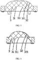
FIG. 7 is a cross-sectional schematic view of a lighting device according toEmbodiment 2 of the present invention; and -
FIG. 8 is a cross-sectional schematic view of a lighting device according toEmbodiment 3 of the present invention; - In order to make objects, technical details and advantages of the present invention apparent, the technical solutions of the present invention will be described in a clearly and fully understandable way in connection with the specific embodiments of the present invention and the corresponding drawings. It is obvious that the described embodiments are just a part but not all of the embodiments of the present invention. Based on the embodiments described herein, those ordinarily skilled in the art can obtain other embodiment(s), without any inventive work, which should be within the scope of the present invention.
- In conjunction with
FIG. 1 to FIG. 6 ,Embodiment 1 of the present invention provides alighting device 100, comprising alight body 1, a light source module mounted in thelight body 1, and afront cover 4 covering the light source module, in which, the light source module includes a light-emitting component 2 and a plurality oflenses 3 that distribute light from the light-emitting component 2, and light emitted from thelens 3 is emitted through thefront cover 4. Thelighting device 100 provided by the embodiment of the present invention for example is applied as a street lamp; aheat radiator 5, areflector 6, and a driving power supply component (not shown) are further provided in thelight body 1; and a cushion ring 7 is further provided between thelight body 1 and thefront cover 4. - Hereinafter, respective elements in the
lighting device 100 provided byEmbodiment 1 of the present invention and configuration relationships between the elements will be described in detail. - Referring to
FIG. 2 , thelight body 1 is formed with an accommodating space; and the light-emitting component 2, thelens 3, theheat radiator 5 and thereflector 6 are all accommodated in the accommodating space, in which, theheat radiator 5 is provided below the light-emitting component 2, and thereflector 6 is provided on a periphery of the light source module. In this embodiment, thereflector 6 causes diffuse reflection; and because the light-emitting component 2 according to this embodiment sinks a bit, in order to further improve light-emitting efficiency of the light source module, thereflector 6 is provided so that a small portion of light emitted by the light source module that otherwise is not incident on thefront cover 4 is reflected by thereflector 6 to thefront cover 4 and then is emitted from thefront cover 4. In other alternative embodiments, in a case where a position of the light-emitting component 2 is flush with a bottom of thefront cover 4, thereflector 6 may not be provided. - The
front cover 4 includes a lighttransmissive portion 41 corresponding to the light source module and a coatedportion 42 not corresponding to the light source module. The lighttransmissive portion 41 is made of transparent glass, which allows light emitted by the light source module to pass through. The coatedportion 42 has a layer of opaque material coated on the transparent glass to shield a portion inside thelight body 1 where no light source module is provided, so that the lighting device is more beautiful. The opaque material coated to the coatedportion 42 is preferably a high temperature resistant material, which prevents the coated opaque material from falling off or aging during the lighting device works at a high temperature.FIG. 1 only schematically shows a stretched arc-shaped front cover, but the shape of thefront cover 4 is not limited to the stretched shape; as long as a condition of the incident angle is satisfied, the arc of thefront cover 4 may be irregular. - Referring to
FIG. 2 andFIG. 3 , the light-emitting component 2 includes a light source board 21 and a plurality oflight emitting units 22 provided on the light source board 21. Thelight emitting units 22 may be arranged in one row or several rows. In this embodiment, thelight emitting units 22 are arranged in an array on the light source board 21. Thelight emitting unit 22 is an LED light source. In other alternative embodiments, severallight emitting units 22 correspond to onelens 3. - Referring to
FIG. 3 to FIG. 6 , thelens 3 has aninner surface 31, anouter surface 32, and anaccommodating chamber 30 enclosed by theinner surface 31; and thelight emitting unit 22 is accommodated in theaccommodating chamber 30. Referring to the stereoscopic view of thelens 3 shown inFIG. 4 , thelens 3 has an axisymmetric structure; a length direction of thelens 3 is defined as a longitudinal direction; a width direction of thelens 3 is defined as a lateral direction; an intersection point of a central line of thelens 3 in the longitudinal direction and a central line of thelens 3 in the lateral direction is a geometric center O point; and a cross-section passing through the geometric center O point of thelens 3 is a central cross-section. In conjunction withFIG. 4 to FIG. 6 , thelens 3 includes two types of cross-sectional profiles respectively in the longitudinal direction and the lateral direction. Referring toFIG. 5 , the central cross-sectional profile in the longitudinal direction of thelens 3 is defined as a first profile; referring toFIG. 6 , the central cross-sectional profile of thelens 3 in the lateral direction is defined as a second profile. In other alternative embodiments, thelight incident surface 31 and thelight emission surface 32 of thelens 3 may have other configurations. - The first profile includes a first
light incident surface 311 and a firstlight emission surface 321; the firstlight incident surface 311 belongs to theinner surface 31; and the firstlight emission surface 321 belongs to theouter surface 32. The first profile is an axisymmetric pattern. The firstlight incident surface 311 and the firstlight emission surface 321 are both regular curved surfaces; and a curvature of the firstlight incident surface 311 is greater than a curvature of the firstlight emission surface 321. In this embodiment, the firstlight incident surface 311 is a semi-ellipsoid; and the firstlight emission surface 321 is an axisymmetric curved surface. - The second profile includes a second light incident surface 312 and a second light emission surface 322; the second light incident surface 312 belongs to the
inner surface 31; and the second light emission surface 322 belongs to theouter surface 32. Both the second light incident surface 312 and the second light emission surface 322 are regular curved surfaces and are axisymmetric patterns, but the second profile is a non-axisymmetric pattern, that is, a symmetry axis of the second light incident surface 312 is parallel to but not coincident with a symmetry axis of the of the second light emission surface 322. In this embodiment, the second light incident surface 312 and the second light emission surface 322 are both semi-ellipsoids. - In this embodiment, in the longitudinal direction, a position corresponding to maximum intensity after light distribution by the
lens 3 is at an angle of 75 °. - In order to reduce reflectance of the
light transmissive portion 41 to light emitted at a large angle, it is necessary to reduce an incident angle, incident to thelight transmissive portion 41, of the light emitted at the large angle; that is, it is necessary to reduce an included angle between the light emitted at a large angle and a corresponding normal line at an incident point thereof on thelight transmissive portion 41, and thus, thelight transmissive portion 41 is designed to have an arc shape. Thelight transmissive portion 41 may be made of glass or plastic. - A height h of the
light transmissive portion 41 is a distance between a highest point and a lowest point of an inner surface of thelight transmissive portion 41, and a length of thelight transmissive portion 41 is a distance between two end points of the inner surface of thelight transmissive portion 41 in the longitudinal direction. In this embodiment, a cross-section of thelight transmissive portion 41 is semicircular, that is, the height h of thelight transmissive portion 41 is 1/2 of the length b of thelight transmissive portion 41. A lens located at the center is defined as a center lens 3a; and light emitted from the center lens 3a at an angle of 75 ° has an incident angle α1 of 8 ° when incident on thelight transmissive portion 41, which, thus, greatly reduces change in light intensity when the light emitted at an angle corresponding to maximum intensity is emitted through thefront cover 4, so that a smaller light distribution change occurs during the light is emitted through thelight transmissive portion 41. It is concluded that, in a case where the cross-section of thelight transmissive portion 41 is semicircular, even if a profile of the center lens 3a is any other profile, regardless of whichever angle the light corresponding to the maximum intensity after distribution is located at, the incident angle of the light on thelight transmissive portion 41 is not larger than 8 °. - A lens farthest from the center is defined as an
edge lens 3b; among all the incident angles of the light incident on thelight transmissive portion 41, an incident angle of a certain beam of light emitted from theedge lens 3b is a maximum incident angle, which is a critical value. Referring toFIG. 1 , light from theedge lens 3b has a maximum incident angle α2 of 36° when incident on thelight transmissive portion 41. Then, in this embodiment, thelight transmissive portion 41 satisfies that incident angles corresponding to all light incident to any point of thelight transmissive portion 41 are all smaller than A, where A is 36 °. If a distance between theedge lens 3b and the center lens 3a is larger, A may be larger than 36 °, but must be smaller than 45 °. From correspondence relationship between the incident angle and the reflectance in Table 1, it can be seen that, the reflectance increases significantly after the incident angle is larger than 45 °, while the reflectance changes little when the incident angle is smaller than 45 °. Therefore, the present invention controls a part that is necessary to effectively control the reflectance, that is, makes the incident angle less than 45 °. - The incident angle is controlled within 45 °, that is, light transmittance of the
light transmissive portion 41 is controlled above 90%, which greatly reduces change in light intensity of all light incident on thelight transmissive portion 41 so that a smaller light distribution change occurs during the light is emitted through thelight transmissive portion 41, and improves the light distribution efficiency of thelighting device 100. - Referring to
FIG. 5 ,Embodiment 2 of the present invention provides a lighting device 100', comprising a light body 1', a light source module mounted in the light body 1', and a light transmissive portion 41' covering the light source module, in which, the light source module includes a light-emitting component 2' and a plurality of lenses 3' that distribute light from the light-emitting component 2', and light emitted from the lens 3' is emitted through the light transmissive portion 41'. - In the lighting device 100', except for that a structure of the light transmissive portion 41' is different from the structure of the
light transmissive portion 41 in thelighting device 100 according toEmbodiment 1, other structures such as the light body 1', the light-emitting component 2' and the lens 3' as well as modes they combine with each other are the same as those according toEmbodiment 1. - The light transmissive portion 41' is arc-shaped; and in this embodiment, a height h' of the light transmissive portion 41' is 1/4 of a length b' of the light transmissive portion 41'. Light emitted from a center lens 3a' at an angle of 75 ° has an incident angle α1' of 28 ° when incident on the light transmissive portion 41', which, thus, greatly reduces change in light intensity when the light emitted at an angle corresponding to maximum intensity is emitted through the front cover 4', so that a smaller light distribution change occurs during the light is emitted through the light transmissive portion 41'. It is concluded that, in this embodiment, even if a profile of the center lens 3a' is any other profile, regardless of whichever angle light corresponding to the maximum intensity after distribution is located at, the incident angle of the light on the light transmissive portion 41' is not larger than 28 °.
- A lens farthest from the center is defined as an
edge lens 3b'; among all the incident angles of the light incident on the light transmissive portion 41', an incident angle of a certain beam of light emitted from theedge lens 3b' is a maximum incident angle, which is a critical value. Referring toFIG. 5 , light from theedge lens 3b' has a maximum incident angle α2' of 38 ° when incident on the light transmissive portion 41'. Then, in this embodiment, the light transmissive portion 41' satisfies that incident angles corresponding to all light incident to any point of the light transmissive portion 41' are all smaller than A', where A' is 38 °. If a distance between theedge lens 3b' and the center lens 3a' is larger, A' may be larger than 38 °, but must be smaller than 45 °, which, thus, greatly reduces change in light intensity of all light incident on the light transmissive portion 41', so that a smaller light distribution change occurs during the light is emitted through the light transmissive portion 41', and improves the light distribution efficiency of the lighting device 100'. - Referring to
FIG. 6 ,Embodiment 3 of the present invention provides alighting device 100", comprising alight body 1", a light source module mounted in thelight body 1", and alight transmissive portion 41" covering the light source module, in which, the light source module includes a light-emittingcomponent 2" and a plurality oflenses 3" that distribute light from the light-emittingcomponent 2", and light emitted from thelens 3" is emitted through thelight transmissive portion 41". - In the
lighting device 100", except for that a structure of thelight transmissive portion 41" is different from the structure of thefront cover 4 in thelighting device 100 according toEmbodiment 1, other structures such as thelight body 1", the light-emittingcomponent 2" and thelens 3" as well as modes they combine with each other are the same as those according toEmbodiment 1. - The
light transmissive portion 41" is arc-shaped; and in this embodiment, a height h" of thelight transmissive portion 41" is 1/6.3 of a length b" of thelight transmissive portion 41". Light emitted from a center lens 3a" at an angle of 75° has an incident angle α1" of 45 ° when incident on thelight transmissive portion 41", which, thus, greatly reduces change in light intensity when the light emitted at an angle corresponding to maximum intensity is emitted through thelight transmissive portion 41", so that a smaller light distribution change occurs during the light is emitted through thelight transmissive portion 41". It is concluded that, in this embodiment, even if a profile of the center lens 3a" is any other profile, regardless of whichever angle light corresponding to the maximum intensity after distribution is located at, the incident angle of the light on thelight transmissive portion 41" is smaller than 45 °. - A lens farthest from the center is defined as an
edge lens 3b"; among all the incident angles of the light incident on thelight transmissive portion 41", an incident angle of a certain beam of light emitted from theedge lens 3b" is a maximum incident angle, which is a critical value. Referring toFIG. 6 , light from theedge lens 3b" has a maximum incident angle α2" of 43 ° when incident on thelight transmissive portion 41". Then, in this embodiment, thelight transmissive portion 41" satisfies that incident angles corresponding to all light incident to any point of thelight transmissive portion 41" are all smaller than A", where A" is 43 °. If a distance between theedge lens 3b" and the center lens 3a" is larger, A" may be larger than 43 °, but must be smaller than 45 °, which, thus, greatly reduces change in light intensity of all light incident on thelight transmissive portion 41", so that a smaller light distribution change occurs during the light is emitted through thelight transmissive portion 41", and improves the light distribution efficiency of thelighting device 100". - The objects, technical solutions and beneficial effects of the present invention are further explained in detail in the specific embodiments as described above. It should be understood that the foregoing embodiments merely are specific embodiments of the present invention, and not intended to limit the present invention. Any modification, equivalent substitution, improvement, and the like, made within the spirit and principles of the present invention should be covered within the protection scope of the present invention.
Claims (17)
- A lighting device, comprising a light body, a light source module mounted in the light body, and a light transmissive portion covering the light source module, wherein,
the light source module includes a plurality of lenses and a light emitting unit accommodated in the lens, and light emitted by the light emitting unit is emitted from the light transmissive portion after being distributed by the lens,
the light transmissive portion is arc-shaped, and an incident angle corresponding to incident light at any point of the light transmissive portion is smaller than 45°. - The lighting device according to claim 1, wherein, a length direction of the lens is a longitudinal direction, a width direction of the lens is a lateral direction, and a central cross-sectional profile of the lens in the longitudinal direction and a central cross-sectional profile of the lens in the lateral direction are different from each other.
- The lighting device according to claim 2, wherein, the central cross-sectional profile of the lens in the longitudinal direction is a first profile, the first profile is an axisymmetric pattern, and the first profile includes a first light incident surface and a first light emission surface.
- The lighting device according to claim 3, wherein, a curvature of the first light incident surface is greater than a curvature of the first light emission surface.
- The lighting device according to claim 3, wherein, the first light incident surface is a semi-ellipsoid, and the first light emission surface is an axisymmetric curved surface.
- The lighting device according to claim 2, wherein, the central cross-sectional profile of the lens in the lateral direction is a second profile, an outer surface and an inner surface of the second profile are both axisymmetric patterns, and a symmetry axis of the outer surface of the second profile and a symmetry axis of the inner surface of the second profile are parallel to each other.
- The lighting device according to claim 1, wherein, an angle corresponding to maximum intensity of light distributed by the lens is between 70° and 80°, and an incident angle of light corresponding to the maximum intensity in all light that is incident on the light transmissive portion is between 8° and 45°.
- The lighting device according to claim 1, wherein, a height of the light transmissive portion is 1/6.3 to 1/2 of a length of the light transmissive portion.
- The lighting device according to claim 1, wherein, the light transmissive portion is made of glass or plastic.
- The lighting device according to claim 1, wherein, the lighting device further comprises a light-emitting component, the light-emitting component includes a light source board and a plurality of the light emitting units provided on the light source board, and one of the lenses corresponds to one of the light emitting units or corresponds to several ones the light emitting units.
- The lighting device according to claim 1, wherein, light transmittance of the light transmissive portion is greater than 90%.
- The lighting device according to claim 1, wherein, the lighting device is a street lamp.
- The lighting device according to claim 12, wherein, the street lamp further includes a driving power supply component accommodated in the light body, and the driving power supply component is electrically connected with the light source module.
- The lighting device according to claim 13, wherein, the street lamp further includes a front cover connected with the light body, and the front cover includes a coated portion and the light transmissive portion.
- The lighting device according to claim 12, 13 or 14, wherein, the street lamp further includes a lamp pole, and the light body is mounted on the lamp pole.
- The lighting device according to claim 12, wherein, the light emitting units and the lens units are all arranged in an array.
- The lighting device according to claim 12 or 16, wherein, the lighting device further comprises a reflector provided in the light body, and the reflector is provided on a periphery of the light source module.
Applications Claiming Priority (5)
| Application Number | Priority Date | Filing Date | Title |
|---|---|---|---|
| CN201721258961.8U CN207162341U (en) | 2017-09-28 | 2017-09-28 | A kind of lighting device |
| CN201710900652.4A CN107477517A (en) | 2017-09-28 | 2017-09-28 | A kind of lighting device |
| CN201710897781.2A CN107477478B (en) | 2017-09-28 | 2017-09-28 | Lighting device |
| CN201721265861.8U CN207778325U (en) | 2017-09-28 | 2017-09-28 | A kind of lighting device |
| PCT/CN2018/107376 WO2019062718A1 (en) | 2017-09-28 | 2018-09-25 | Lighting device |
Publications (3)
| Publication Number | Publication Date |
|---|---|
| EP3690311A1 true EP3690311A1 (en) | 2020-08-05 |
| EP3690311A4 EP3690311A4 (en) | 2021-04-07 |
| EP3690311B1 EP3690311B1 (en) | 2024-12-04 |
Family
ID=65900717
Family Applications (1)
| Application Number | Title | Priority Date | Filing Date |
|---|---|---|---|
| EP18862283.1A Active EP3690311B1 (en) | 2017-09-28 | 2018-09-25 | Lighting device |
Country Status (3)
| Country | Link |
|---|---|
| US (1) | US11131439B2 (en) |
| EP (1) | EP3690311B1 (en) |
| WO (1) | WO2019062718A1 (en) |
Families Citing this family (3)
| Publication number | Priority date | Publication date | Assignee | Title |
|---|---|---|---|---|
| EP3564579B1 (en) * | 2017-05-27 | 2023-08-16 | Suzhou Opple Lighting Co., Ltd. | Light distribution element, light source module and lighting device |
| CN112781012A (en) * | 2021-01-19 | 2021-05-11 | 海洋王(东莞)照明科技有限公司 | Lamp capable of emitting light uniformly |
| US12078334B2 (en) * | 2022-05-18 | 2024-09-03 | Express Imaging Systems, Llc | Luminaire with glare control |
Family Cites Families (30)
| Publication number | Priority date | Publication date | Assignee | Title |
|---|---|---|---|---|
| US5235252A (en) * | 1991-12-31 | 1993-08-10 | Blake Frederick H | Fiber-optic anti-cycling device for street lamps |
| US6784357B1 (en) * | 2002-02-07 | 2004-08-31 | Chao Hsiang Wang | Solar energy-operated street-lamp system |
| KR101136344B1 (en) * | 2005-04-06 | 2012-04-18 | 삼성전자주식회사 | Optical lens, optical module having the optical lens, back light assembly having the optical module and display apparatus having the back light assembly |
| US7420811B2 (en) * | 2006-09-14 | 2008-09-02 | Tsung-Wen Chan | Heat sink structure for light-emitting diode based streetlamp |
| US8092042B2 (en) * | 2007-05-03 | 2012-01-10 | Ruud Lighting, Inc. | Shield member in LED apparatus |
| CN101106854B (en) * | 2007-08-13 | 2011-09-14 | 东莞勤上光电股份有限公司 | An energy-saving LED road lamp |
| WO2009026736A1 (en) * | 2007-08-24 | 2009-03-05 | He Shan Lide Electronic Enterprise Company Ltd. | An led street lamp |
| US7637630B2 (en) * | 2008-04-22 | 2009-12-29 | Ruud Lighting, Inc. | Integrated shield-gasket member in LED apparatus |
| TWM364168U (en) * | 2009-04-03 | 2009-09-01 | Genius Electronic Optical Co Ltd | Light emitting device |
| US8310158B2 (en) * | 2009-09-23 | 2012-11-13 | Ecofit Lighting, LLC | LED light engine apparatus |
| CN102261617A (en) * | 2010-05-31 | 2011-11-30 | 富士迈半导体精密工业(上海)有限公司 | Lampshades and lamps using the same |
| KR101123448B1 (en) * | 2010-06-14 | 2012-03-23 | 윤동한 | High-power Photonic Device Street Light Using a Thermocouple |
| TW201200798A (en) * | 2010-06-25 | 2012-01-01 | Alliance Optotek Co Ltd | Optic element of lighting device and design method thereof |
| US8331037B2 (en) * | 2010-08-30 | 2012-12-11 | Edison Opto Corporation | Optical lens |
| US20120051047A1 (en) * | 2010-08-30 | 2012-03-01 | Edison Opto Corporation | Street lamp |
| TWI461629B (en) * | 2012-02-01 | 2014-11-21 | 台達電子工業股份有限公司 | Illuminating apparatus and illuminating module thereof |
| CN202791792U (en) * | 2012-08-10 | 2013-03-13 | 霍永峰 | Lampshade and light-emitting diode (LED) lamp utilizing the same |
| JP2015015281A (en) * | 2013-07-03 | 2015-01-22 | ウシオ電機株式会社 | Light emitting device |
| JP6238163B2 (en) * | 2013-11-05 | 2017-11-29 | パナソニックIpマネジメント株式会社 | Lighting device and lighting fixture |
| US9732936B2 (en) * | 2014-01-21 | 2017-08-15 | Bridgelux Inc. | Optics for chip-on-board road and area lighting |
| CN103807806B (en) * | 2014-01-22 | 2016-01-20 | 宏力照明集团有限公司 | The light distributing method of the COB module LED street lamp lens in 3,5 tracks can be irradiated to |
| US9470394B2 (en) * | 2014-11-24 | 2016-10-18 | Cree, Inc. | LED light fixture including optical member with in-situ-formed gasket and method of manufacture |
| CN104654196A (en) * | 2015-02-12 | 2015-05-27 | 德阳市恒达灯具制造有限公司 | LED (Light-Emitting Diode) lampshade |
| CN104864295B (en) * | 2015-05-29 | 2017-05-10 | 广东浩迪光电技术有限公司 | Light transmitting cover promoting illuminance evenness |
| KR102402258B1 (en) * | 2015-06-10 | 2022-05-27 | 쑤저우 레킨 세미컨덕터 컴퍼니 리미티드 | Light emitting unit and light source unit including the same |
| CN106051515B (en) * | 2016-05-30 | 2019-06-14 | 众普森科技(株洲)有限公司 | One kind is with light unit and matches optical assembly |
| KR102683383B1 (en) * | 2016-08-18 | 2024-07-15 | 서울반도체 주식회사 | Light emitting module and lens |
| CN206347451U (en) * | 2016-11-26 | 2017-07-21 | 扬州润光照明电器有限公司 | A kind of efficient energy-saving LED road lamp |
| CN107477517A (en) * | 2017-09-28 | 2017-12-15 | 欧普道路照明有限公司 | A kind of lighting device |
| CN107477478B (en) * | 2017-09-28 | 2023-06-30 | 欧普道路照明有限公司 | Lighting device |
-
2018
- 2018-09-25 EP EP18862283.1A patent/EP3690311B1/en active Active
- 2018-09-25 WO PCT/CN2018/107376 patent/WO2019062718A1/en not_active Ceased
-
2020
- 2020-03-25 US US16/829,551 patent/US11131439B2/en active Active
Also Published As
| Publication number | Publication date |
|---|---|
| US11131439B2 (en) | 2021-09-28 |
| EP3690311B1 (en) | 2024-12-04 |
| WO2019062718A1 (en) | 2019-04-04 |
| EP3690311A4 (en) | 2021-04-07 |
| US20200224852A1 (en) | 2020-07-16 |
Similar Documents
| Publication | Publication Date | Title |
|---|---|---|
| US7008079B2 (en) | Composite reflecting surface for linear LED array | |
| US10422943B2 (en) | Luminaire with light guide | |
| EP2769142B2 (en) | Lighting device with omnidirectional light distribution | |
| CN112254026B (en) | Anti-dazzle lamp and illumination arrangement method adopting same | |
| EP3690311B1 (en) | Lighting device | |
| JP2015103323A (en) | Lighting device | |
| US10775014B2 (en) | Vehicle headlight assembly and a corresponding lamp | |
| CN103511935A (en) | Lighting device | |
| CN107477517A (en) | A kind of lighting device | |
| EP2034237A1 (en) | Energy-saving lampshade with even light distribution | |
| WO2024067239A1 (en) | Subtraction table lamp | |
| KR20220098713A (en) | Lighting apparatus | |
| CN207778325U (en) | A kind of lighting device | |
| KR20160144783A (en) | Lighting apparatus | |
| CN204026514U (en) | All-round smooth LED | |
| CN107477478B (en) | Lighting device | |
| CN217635169U (en) | Anti-dazzle lighting visual optical assembly and spot lamp | |
| EP3957905B1 (en) | Anti-glare lamp and lighting arrangement method using the lamp | |
| CN110242933A (en) | A kind of LED tri-proof light | |
| CN102620239B (en) | Floodlight reflector and light emitting diode (LED) luminaire | |
| CN209876649U (en) | Glare-free tunnel lamp | |
| CN107676681B (en) | Anti-dazzle narrow-beam LED lamp | |
| CN102620238B (en) | Floodlight reflector and light-emitting diode (LED) lamp | |
| CN102620236B (en) | Floodlight reflector and LED lamp | |
| KR101571486B1 (en) | Large optical lens with devided light distribution |
Legal Events
| Date | Code | Title | Description |
|---|---|---|---|
| STAA | Information on the status of an ep patent application or granted ep patent |
Free format text: STATUS: THE INTERNATIONAL PUBLICATION HAS BEEN MADE |
|
| PUAI | Public reference made under article 153(3) epc to a published international application that has entered the european phase |
Free format text: ORIGINAL CODE: 0009012 |
|
| STAA | Information on the status of an ep patent application or granted ep patent |
Free format text: STATUS: REQUEST FOR EXAMINATION WAS MADE |
|
| 17P | Request for examination filed |
Effective date: 20200327 |
|
| AK | Designated contracting states |
Kind code of ref document: A1 Designated state(s): AL AT BE BG CH CY CZ DE DK EE ES FI FR GB GR HR HU IE IS IT LI LT LU LV MC MK MT NL NO PL PT RO RS SE SI SK SM TR |
|
| AX | Request for extension of the european patent |
Extension state: BA ME |
|
| DAV | Request for validation of the european patent (deleted) | ||
| DAX | Request for extension of the european patent (deleted) | ||
| A4 | Supplementary search report drawn up and despatched |
Effective date: 20210309 |
|
| RIC1 | Information provided on ipc code assigned before grant |
Ipc: F21V 5/04 20060101ALI20210302BHEP Ipc: F21V 3/02 20060101AFI20210302BHEP Ipc: F21S 8/08 20060101ALI20210302BHEP Ipc: F21V 5/00 20180101ALI20210302BHEP Ipc: F21V 5/08 20060101ALI20210302BHEP Ipc: F21W 131/103 20060101ALI20210302BHEP |
|
| STAA | Information on the status of an ep patent application or granted ep patent |
Free format text: STATUS: EXAMINATION IS IN PROGRESS |
|
| 17Q | First examination report despatched |
Effective date: 20220920 |
|
| GRAP | Despatch of communication of intention to grant a patent |
Free format text: ORIGINAL CODE: EPIDOSNIGR1 |
|
| STAA | Information on the status of an ep patent application or granted ep patent |
Free format text: STATUS: GRANT OF PATENT IS INTENDED |
|
| INTG | Intention to grant announced |
Effective date: 20240711 |
|
| GRAS | Grant fee paid |
Free format text: ORIGINAL CODE: EPIDOSNIGR3 |
|
| GRAA | (expected) grant |
Free format text: ORIGINAL CODE: 0009210 |
|
| STAA | Information on the status of an ep patent application or granted ep patent |
Free format text: STATUS: THE PATENT HAS BEEN GRANTED |
|
| AK | Designated contracting states |
Kind code of ref document: B1 Designated state(s): AL AT BE BG CH CY CZ DE DK EE ES FI FR GB GR HR HU IE IS IT LI LT LU LV MC MK MT NL NO PL PT RO RS SE SI SK SM TR |
|
| REG | Reference to a national code |
Ref country code: GB Ref legal event code: FG4D |
|
| REG | Reference to a national code |
Ref country code: CH Ref legal event code: EP |
|
| REG | Reference to a national code |
Ref country code: DE Ref legal event code: R096 Ref document number: 602018077352 Country of ref document: DE |
|
| REG | Reference to a national code |
Ref country code: IE Ref legal event code: FG4D |
|
| REG | Reference to a national code |
Ref country code: NL Ref legal event code: FP |
|
| REG | Reference to a national code |
Ref country code: LT Ref legal event code: MG9D |
|
| PG25 | Lapsed in a contracting state [announced via postgrant information from national office to epo] |
Ref country code: HR Free format text: LAPSE BECAUSE OF FAILURE TO SUBMIT A TRANSLATION OF THE DESCRIPTION OR TO PAY THE FEE WITHIN THE PRESCRIBED TIME-LIMIT Effective date: 20241204 |
|
| PG25 | Lapsed in a contracting state [announced via postgrant information from national office to epo] |
Ref country code: FI Free format text: LAPSE BECAUSE OF FAILURE TO SUBMIT A TRANSLATION OF THE DESCRIPTION OR TO PAY THE FEE WITHIN THE PRESCRIBED TIME-LIMIT Effective date: 20241204 |
|
| PG25 | Lapsed in a contracting state [announced via postgrant information from national office to epo] |
Ref country code: BG Free format text: LAPSE BECAUSE OF FAILURE TO SUBMIT A TRANSLATION OF THE DESCRIPTION OR TO PAY THE FEE WITHIN THE PRESCRIBED TIME-LIMIT Effective date: 20241204 |
|
| PG25 | Lapsed in a contracting state [announced via postgrant information from national office to epo] |
Ref country code: ES Free format text: LAPSE BECAUSE OF FAILURE TO SUBMIT A TRANSLATION OF THE DESCRIPTION OR TO PAY THE FEE WITHIN THE PRESCRIBED TIME-LIMIT Effective date: 20241204 |
|
| PG25 | Lapsed in a contracting state [announced via postgrant information from national office to epo] |
Ref country code: NO Free format text: LAPSE BECAUSE OF FAILURE TO SUBMIT A TRANSLATION OF THE DESCRIPTION OR TO PAY THE FEE WITHIN THE PRESCRIBED TIME-LIMIT Effective date: 20250304 |
|
| PG25 | Lapsed in a contracting state [announced via postgrant information from national office to epo] |
Ref country code: LV Free format text: LAPSE BECAUSE OF FAILURE TO SUBMIT A TRANSLATION OF THE DESCRIPTION OR TO PAY THE FEE WITHIN THE PRESCRIBED TIME-LIMIT Effective date: 20241204 Ref country code: GR Free format text: LAPSE BECAUSE OF FAILURE TO SUBMIT A TRANSLATION OF THE DESCRIPTION OR TO PAY THE FEE WITHIN THE PRESCRIBED TIME-LIMIT Effective date: 20250305 |
|
| PG25 | Lapsed in a contracting state [announced via postgrant information from national office to epo] |
Ref country code: RS Free format text: LAPSE BECAUSE OF FAILURE TO SUBMIT A TRANSLATION OF THE DESCRIPTION OR TO PAY THE FEE WITHIN THE PRESCRIBED TIME-LIMIT Effective date: 20250304 |
|
| REG | Reference to a national code |
Ref country code: AT Ref legal event code: MK05 Ref document number: 1748529 Country of ref document: AT Kind code of ref document: T Effective date: 20241204 |
|
| PG25 | Lapsed in a contracting state [announced via postgrant information from national office to epo] |
Ref country code: SM Free format text: LAPSE BECAUSE OF FAILURE TO SUBMIT A TRANSLATION OF THE DESCRIPTION OR TO PAY THE FEE WITHIN THE PRESCRIBED TIME-LIMIT Effective date: 20241204 |
|
| PG25 | Lapsed in a contracting state [announced via postgrant information from national office to epo] |
Ref country code: PL Free format text: LAPSE BECAUSE OF FAILURE TO SUBMIT A TRANSLATION OF THE DESCRIPTION OR TO PAY THE FEE WITHIN THE PRESCRIBED TIME-LIMIT Effective date: 20241204 |
|
| PG25 | Lapsed in a contracting state [announced via postgrant information from national office to epo] |
Ref country code: IS Free format text: LAPSE BECAUSE OF FAILURE TO SUBMIT A TRANSLATION OF THE DESCRIPTION OR TO PAY THE FEE WITHIN THE PRESCRIBED TIME-LIMIT Effective date: 20250404 |
|
| PG25 | Lapsed in a contracting state [announced via postgrant information from national office to epo] |
Ref country code: PT Free format text: LAPSE BECAUSE OF FAILURE TO SUBMIT A TRANSLATION OF THE DESCRIPTION OR TO PAY THE FEE WITHIN THE PRESCRIBED TIME-LIMIT Effective date: 20250404 |
|
| PG25 | Lapsed in a contracting state [announced via postgrant information from national office to epo] |
Ref country code: EE Free format text: LAPSE BECAUSE OF FAILURE TO SUBMIT A TRANSLATION OF THE DESCRIPTION OR TO PAY THE FEE WITHIN THE PRESCRIBED TIME-LIMIT Effective date: 20241204 |
|
| PG25 | Lapsed in a contracting state [announced via postgrant information from national office to epo] |
Ref country code: RO Free format text: LAPSE BECAUSE OF FAILURE TO SUBMIT A TRANSLATION OF THE DESCRIPTION OR TO PAY THE FEE WITHIN THE PRESCRIBED TIME-LIMIT Effective date: 20241204 Ref country code: AT Free format text: LAPSE BECAUSE OF FAILURE TO SUBMIT A TRANSLATION OF THE DESCRIPTION OR TO PAY THE FEE WITHIN THE PRESCRIBED TIME-LIMIT Effective date: 20241204 |
|
| PG25 | Lapsed in a contracting state [announced via postgrant information from national office to epo] |
Ref country code: SK Free format text: LAPSE BECAUSE OF FAILURE TO SUBMIT A TRANSLATION OF THE DESCRIPTION OR TO PAY THE FEE WITHIN THE PRESCRIBED TIME-LIMIT Effective date: 20241204 |
|
| PG25 | Lapsed in a contracting state [announced via postgrant information from national office to epo] |
Ref country code: CZ Free format text: LAPSE BECAUSE OF FAILURE TO SUBMIT A TRANSLATION OF THE DESCRIPTION OR TO PAY THE FEE WITHIN THE PRESCRIBED TIME-LIMIT Effective date: 20241204 |
|
| PG25 | Lapsed in a contracting state [announced via postgrant information from national office to epo] |
Ref country code: IT Free format text: LAPSE BECAUSE OF FAILURE TO SUBMIT A TRANSLATION OF THE DESCRIPTION OR TO PAY THE FEE WITHIN THE PRESCRIBED TIME-LIMIT Effective date: 20241204 |
|
| REG | Reference to a national code |
Ref country code: DE Ref legal event code: R097 Ref document number: 602018077352 Country of ref document: DE |
|
| PG25 | Lapsed in a contracting state [announced via postgrant information from national office to epo] |
Ref country code: SE Free format text: LAPSE BECAUSE OF FAILURE TO SUBMIT A TRANSLATION OF THE DESCRIPTION OR TO PAY THE FEE WITHIN THE PRESCRIBED TIME-LIMIT Effective date: 20241204 |
|
| PG25 | Lapsed in a contracting state [announced via postgrant information from national office to epo] |
Ref country code: DK Free format text: LAPSE BECAUSE OF FAILURE TO SUBMIT A TRANSLATION OF THE DESCRIPTION OR TO PAY THE FEE WITHIN THE PRESCRIBED TIME-LIMIT Effective date: 20241204 |
|
| PGFP | Annual fee paid to national office [announced via postgrant information from national office to epo] |
Ref country code: DE Payment date: 20250916 Year of fee payment: 8 |
|
| PLBE | No opposition filed within time limit |
Free format text: ORIGINAL CODE: 0009261 |
|
| STAA | Information on the status of an ep patent application or granted ep patent |
Free format text: STATUS: NO OPPOSITION FILED WITHIN TIME LIMIT |
|
| PGFP | Annual fee paid to national office [announced via postgrant information from national office to epo] |
Ref country code: NL Payment date: 20250909 Year of fee payment: 8 |
|
| REG | Reference to a national code |
Ref country code: CH Ref legal event code: L10 Free format text: ST27 STATUS EVENT CODE: U-0-0-L10-L00 (AS PROVIDED BY THE NATIONAL OFFICE) Effective date: 20251015 |
|
| PGFP | Annual fee paid to national office [announced via postgrant information from national office to epo] |
Ref country code: BE Payment date: 20250919 Year of fee payment: 8 Ref country code: GB Payment date: 20250919 Year of fee payment: 8 |
|
| PGFP | Annual fee paid to national office [announced via postgrant information from national office to epo] |
Ref country code: FR Payment date: 20250929 Year of fee payment: 8 |
|
| 26N | No opposition filed |
Effective date: 20250905 |
|
| REG | Reference to a national code |
Ref country code: CH Ref legal event code: H13 Free format text: ST27 STATUS EVENT CODE: U-0-0-H10-H13 (AS PROVIDED BY THE NATIONAL OFFICE) Effective date: 20260504 |