EP3690307A1 - Lighting device - Google Patents
Lighting device Download PDFInfo
- Publication number
- EP3690307A1 EP3690307A1 EP18860728.7A EP18860728A EP3690307A1 EP 3690307 A1 EP3690307 A1 EP 3690307A1 EP 18860728 A EP18860728 A EP 18860728A EP 3690307 A1 EP3690307 A1 EP 3690307A1
- Authority
- EP
- European Patent Office
- Prior art keywords
- lighting device
- light
- base member
- lens
- light source
- Prior art date
- Legal status (The legal status is an assumption and is not a legal conclusion. Google has not performed a legal analysis and makes no representation as to the accuracy of the status listed.)
- Withdrawn
Links
- 230000002093 peripheral effect Effects 0.000 claims abstract description 43
- 238000000605 extraction Methods 0.000 claims abstract description 8
- 239000000463 material Substances 0.000 claims description 5
- 239000011248 coating agent Substances 0.000 claims description 3
- 238000000576 coating method Methods 0.000 claims description 3
- 238000005286 illumination Methods 0.000 description 24
- 238000003780 insertion Methods 0.000 description 14
- 230000037431 insertion Effects 0.000 description 14
- 238000009434 installation Methods 0.000 description 7
- 229910052782 aluminium Inorganic materials 0.000 description 4
- XAGFODPZIPBFFR-UHFFFAOYSA-N aluminium Chemical compound [Al] XAGFODPZIPBFFR-UHFFFAOYSA-N 0.000 description 4
- 239000007769 metal material Substances 0.000 description 4
- 239000003973 paint Substances 0.000 description 4
- 239000000758 substrate Substances 0.000 description 4
- 101001124039 Banna virus (strain Indonesia/JKT-6423/1980) Non-structural protein 4 Proteins 0.000 description 3
- 101000933041 His1 virus (isolate Australia/Victoria) Major capsid protein Proteins 0.000 description 3
- 239000011347 resin Substances 0.000 description 3
- 229920005989 resin Polymers 0.000 description 3
- 230000008878 coupling Effects 0.000 description 2
- 238000010168 coupling process Methods 0.000 description 2
- 238000005859 coupling reaction Methods 0.000 description 2
- 238000005516 engineering process Methods 0.000 description 2
- 230000004313 glare Effects 0.000 description 2
- 230000003287 optical effect Effects 0.000 description 2
- 230000001105 regulatory effect Effects 0.000 description 2
- 230000000694 effects Effects 0.000 description 1
- 239000013013 elastic material Substances 0.000 description 1
- 229910052743 krypton Inorganic materials 0.000 description 1
- DNNSSWSSYDEUBZ-UHFFFAOYSA-N krypton atom Chemical compound [Kr] DNNSSWSSYDEUBZ-UHFFFAOYSA-N 0.000 description 1
- 238000004519 manufacturing process Methods 0.000 description 1
- 238000012986 modification Methods 0.000 description 1
- 230000004048 modification Effects 0.000 description 1
- 229920000515 polycarbonate Polymers 0.000 description 1
- 239000004417 polycarbonate Substances 0.000 description 1
Images








Classifications
-
- F—MECHANICAL ENGINEERING; LIGHTING; HEATING; WEAPONS; BLASTING
- F21—LIGHTING
- F21V—FUNCTIONAL FEATURES OR DETAILS OF LIGHTING DEVICES OR SYSTEMS THEREOF; STRUCTURAL COMBINATIONS OF LIGHTING DEVICES WITH OTHER ARTICLES, NOT OTHERWISE PROVIDED FOR
- F21V7/00—Reflectors for light sources
- F21V7/04—Optical design
- F21V7/043—Optical design with cylindrical surface
-
- F—MECHANICAL ENGINEERING; LIGHTING; HEATING; WEAPONS; BLASTING
- F21—LIGHTING
- F21S—NON-PORTABLE LIGHTING DEVICES; SYSTEMS THEREOF; VEHICLE LIGHTING DEVICES SPECIALLY ADAPTED FOR VEHICLE EXTERIORS
- F21S8/00—Lighting devices intended for fixed installation
- F21S8/02—Lighting devices intended for fixed installation of recess-mounted type, e.g. downlighters
- F21S8/026—Lighting devices intended for fixed installation of recess-mounted type, e.g. downlighters intended to be recessed in a ceiling or like overhead structure, e.g. suspended ceiling
-
- F—MECHANICAL ENGINEERING; LIGHTING; HEATING; WEAPONS; BLASTING
- F21—LIGHTING
- F21V—FUNCTIONAL FEATURES OR DETAILS OF LIGHTING DEVICES OR SYSTEMS THEREOF; STRUCTURAL COMBINATIONS OF LIGHTING DEVICES WITH OTHER ARTICLES, NOT OTHERWISE PROVIDED FOR
- F21V29/00—Protecting lighting devices from thermal damage; Cooling or heating arrangements specially adapted for lighting devices or systems
- F21V29/50—Cooling arrangements
- F21V29/70—Cooling arrangements characterised by passive heat-dissipating elements, e.g. heat-sinks
- F21V29/74—Cooling arrangements characterised by passive heat-dissipating elements, e.g. heat-sinks with fins or blades
- F21V29/75—Cooling arrangements characterised by passive heat-dissipating elements, e.g. heat-sinks with fins or blades with fins or blades having different shapes, thicknesses or spacing
-
- F—MECHANICAL ENGINEERING; LIGHTING; HEATING; WEAPONS; BLASTING
- F21—LIGHTING
- F21V—FUNCTIONAL FEATURES OR DETAILS OF LIGHTING DEVICES OR SYSTEMS THEREOF; STRUCTURAL COMBINATIONS OF LIGHTING DEVICES WITH OTHER ARTICLES, NOT OTHERWISE PROVIDED FOR
- F21V7/00—Reflectors for light sources
- F21V7/0008—Reflectors for light sources providing for indirect lighting
- F21V7/0016—Reflectors for light sources providing for indirect lighting on lighting devices that also provide for direct lighting, e.g. by means of independent light sources, by splitting of the light beam, by switching between both lighting modes
-
- F—MECHANICAL ENGINEERING; LIGHTING; HEATING; WEAPONS; BLASTING
- F21—LIGHTING
- F21V—FUNCTIONAL FEATURES OR DETAILS OF LIGHTING DEVICES OR SYSTEMS THEREOF; STRUCTURAL COMBINATIONS OF LIGHTING DEVICES WITH OTHER ARTICLES, NOT OTHERWISE PROVIDED FOR
- F21V7/00—Reflectors for light sources
- F21V7/0025—Combination of two or more reflectors for a single light source
-
- F—MECHANICAL ENGINEERING; LIGHTING; HEATING; WEAPONS; BLASTING
- F21—LIGHTING
- F21Y—INDEXING SCHEME ASSOCIATED WITH SUBCLASSES F21K, F21L, F21S and F21V, RELATING TO THE FORM OR THE KIND OF THE LIGHT SOURCES OR OF THE COLOUR OF THE LIGHT EMITTED
- F21Y2115/00—Light-generating elements of semiconductor light sources
- F21Y2115/10—Light-emitting diodes [LED]
Definitions
- the present invention relates to a lighting device.
- a lighting device in which a layer having a color temperature changing function is provided to the head of a light emitting diode (LED) element has been provided so that the chromaticity changes depending on a location of a light diffuser (such as a shade) serving as a secondary light source.
- a light diffuser such as a shade
- a conical light diffuser becomes a white light secondary light source whose color temperature gradually changes to warm color from the lower part toward the top part.
- Patent Literature 1 Japanese Laid-open Patent Publication No. 2017-092013 Summary
- the color emitted from the lighting device be changeable to a desired color.
- the above-mentioned conventional technology is the configuration in which the color of the light diffuser gradually changes, and it is difficult to enable the color to be changed to a desired color depending on the position of a user.
- the present invention has been made in view of the above, and it is an object thereof to provide a lighting device capable of changing a color recognized by a user depending on a position of the user with respect to the lighting device.
- a lighting device to an embodiment includes a light source, a cylindrical light distribution member disposed on a light extraction direction side of the light source and a colored portion provided along an inner peripheral surface of the light distribution member and colored in a color that reflects light having a predetermined wavelength.
- a color recognized by a user can be changed depending on a position of the user with respect to the lighting device.
- a lighting device 1 as a spotlight (pinhole light) using a lighting unit 2 is described with reference to the drawings.
- the application of the lighting unit is not limited by the lighting device 1 according to the first embodiment described below.
- the lighting unit is not limited to the lighting device 1, and may be used to any type of available lighting devices depending on the purpose.
- the drawings are schematic, and it should be noted that the relation in dimensions of elements and the ratios of the elements may be different from the reality.
- the drawings may have parts where the relation in dimensions or the ratio is different.
- FIG. 1 and FIG. 2 are perspective views illustrating a lighting device according to a first embodiment.
- FIG. 1 is a perspective view of the lighting device 1 as seen from the side where a heat sink 20 is disposed.
- FIG. 2 is a perspective view of the lighting device 1 as seen from the side where a light distribution unit 3 is disposed.
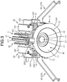
- FIG. 3 is a perspective view illustrating a lighting unit 2 according to the first embodiment.
- the lighting device 1 has the lighting unit 2 and the light distribution unit 3.
- the lighting unit 2 has a frame body 10, the heat sink 20, and a light source portion 30.
- the light distribution unit 3 has a base member 40 as a light distribution member, a lens holder 50 (see FIG. 9 ), and a lens portion 60 (see FIG. 9 ).
- the frame body 10 has a base portion 11 having a bottomed cylindrical shape, and a locking portion 12 protruding from the peripheral edge of the base portion 11 on the opening side.
- the heat sink 20 has a rib portion 201, and four fin portions of a first fin portion 21 to a fourth fin portion 24 continuous to the rib portion 201.
- metal material having high thermal conductivity, such as aluminum, is used for the heat sink 20.
- the first fin portion 21 and the second fin portion 22 are provided at positions sandwiching the rib portion 201.
- the third fin portion 23 and the fourth fin portion 24 are provided at positions sandwiching the rib portion 201.
- Mounting members 25 are coupled to the third fin portion 23 and the fourth fin portion 24. The details are described later.
- the light source portion 30 has a substrate 31 on which a light emitting element 311 is installed on its one surface, and a holding member 32 for holding the substrate 31.
- the light emitting element 311 is a light emitting diode (LED)
- the light source portion 30 may be a chip on board (COB).
- the holding member 32 may be a COB holder.
- a bottom portion 111 of the base portion 11 of the frame body 10 is opened at the center part, and the light source portion 30 is disposed in the opening in the bottom portion 111.
- the light source portion 30 is disposed on the bottom portion 111 of the base portion 11 such that one surface where the light emitting element 311 is installed faces the opening in the base portion 11.
- the direction from the light emitting element 311 toward the opening in the base portion 11 is sometimes referred to as "light extraction direction of light source portion 30".
- the light emitting element 311 emits visible light (hereinafter sometimes simply referred to as "light").
- the heat sink 20 is disposed on the outer surface side of the bottom portion 111 of the base portion 11.
- the rib portion 201 of the heat sink 20 is disposed at a position overlapping the center part of the bottom portion 111.
- a mounting fin 211 of the first fin portion 21 is screwed by a screw member 212 to an insertion hole provided in a mounting portion 112 of the base portion 11.
- a mounting fin 221 of the second fin portion 22 is screwed by a screw member 222 to an insertion hole provided in the mounting portion 112 of the base portion 11. In this manner, the heat sink 20 is mounted to the frame body 10.
- the light source portion 30 is mounted to the heat sink 20 in a manner that the holding member 32 is screwed to an insertion hole provided in the rib portion 201 by a screw member 321 (see FIG. 6 ). In this manner, the light source portion 30 and the heat sink 20 are brought into thermal contact with each other. As described above, the heat sink 20 is provided on the rear surface side of the substrate 31 in the light source portion 30, and hence heat from the substrate 31 can be efficiently transferred to the heat sink 20 on the rear surface side.
- a reflection surface 13 is formed as an inclined surface whose diameter increases toward the opening. In this manner, the reflection surface 13 facing the light extraction direction side is formed on the base portion 11.
- the locking portion 12 is provided on an outer circumference wall of the base portion 11 at a part where the reflection surface 13 is formed.
- three locking portions 12 are provided on the outer circumference wall of the base portion 11 at equal intervals (for example, intervals of 120°) along the outer circumference.
- the three locking portions 12 are provided on the outer circumference wall of the base portion 11 at a part where the reflection surface 13 is formed.
- a placing portion 121 extending in the radial direction is provided at the outer peripheral edge of the base portion 11 on the opening side.
- the placing portion 121 is provided over the entire circumference of the outer circumference wall of the base portion 11 along the outer peripheral edge on the opening side.
- a rotation restricting portion 14 is provided on the outer circumference of the base portion 11 on the bottom portion 111 side.
- the rotation restricting portion 14 has an insertion hole 140 used for screwing.
- three rotation restricting portions 14 are provided on the outer circumference wall of the base portion 11 at equal intervals (for example, intervals of 120°) along the outer peripheral edge on the opening side.
- mounting members 25-1 and 25-2 are coupled to the third fin portion 23 and the fourth fin portion 24 of the heat sink 20, respectively.
- the mounting member 25-1 is coupled to the third fin portion 23, and the mounting member 25-2 is coupled to the fourth fin portion 24.
- the mounting members 25-1 and 25-2 are referred to as “mounting members 25" unless otherwise distinguished.
- FIG. 4 is a plan view illustrating a main part of the lighting device according to the first embodiment. Specifically, FIG. 4 is a view illustrating a connection part between the third fin portion 23 of the heat sink 20 and the mounting member 25-1.
- the mounting member 25 has a spring portion 26 and a shaft support portion 27.
- the spring portion 26 is formed from elastic material.
- the spring portion 26 in the lighting device 1 is a coil spring used to install (mount) the lighting device 1.
- the spring portion 26 has a pair of arm portions 261 extending substantially in parallel to each other with a gap, a pair of coil portions 262 continuous to ends of the arm portions 261 on one side, and a support portion 263 continuous to ends of the arm portion 261 on the other side.
- the shaft support portion 27 has a base portion 271 having a cylindrical shape, and a pair of extended portions 272 extending from both end portions of the base portion 271 in the axial direction of the base portion 271. As illustrated in FIG.
- the shaft support portion 27 is formed such that the diameter of the base portion 271 is larger than the inner diameter of the coil portion 262 and the diameter of the extended portion 272 is smaller than the inner diameter of the coil portion 262.
- the base portion 271 of the shaft support portion 27 is disposed between the pair of coil portions 262 of the spring portion 26, and the pair of extended portions 272 of the shaft support portion 27 are inserted in the corresponding coil portions 262.
- the shaft support portion 27 may be disposed between the pair of coil portions 262.
- the pair of extended portions 272 may be inserted in the corresponding coil portions 262.
- the shaft support portion 27 has a shaft rod 273 to be inserted to through holes (not shown), the through hole being formed in the base portion 271 and the pair of extended portions 272.
- the distal end portion of the shaft rod 273 protrudes from one end portion of the extended portion 272.
- the mounting member 25-1 is coupled to the heat sink 20.
- a C ring 274 is mounted to the distal end portion of the shaft rod 273 protruding from the support fin 231, and the shaft rod 273 is prevented by the C ring 274 from falling off of the through holes in the base portion 271 and the pair of extended portions 272.
- the third fin portion 23 has placement fins 232 between the pair of support fins 231.
- the third fin portion 23 has two placement fins 232.
- the placement fins 232 are formed such that the mounting member 25-1 can be disposed between the pair of support fins 231.
- the placement fin 232 is formed to be partially cut out such that the mounting member 25-1 can be disposed between the pair of support fins 231.
- the mounting member 25 is also coupled to the fourth fin portion 24 similarly to the third fin portion 23. As illustrated in FIG. 2 , when the distal end portion of the shaft rod 273 in the mounting member 25-2 is inserted to insertion holes (not shown) provided in a pair of support fins 241 of the fourth fin portion 24, the mounting member 25-2 is coupled to the heat sink 20. A C ring 274 is mounted to the distal end portion of the shaft rod 273 protruding from the support fin 241, and the shaft rod 273 is prevented by the C ring 274 from falling off of the through holes in the base portion 271 and the pair of extended portions 272.
- the fourth fin portion 24 has placement fins 242 between the pair of support fins 241.
- the fourth fin portion 24 has two placement fins 242.
- the placement fins 242 are formed such that the mounting member 25-2 can be disposed between the pair of support fins 241.
- the placement fin 232 is formed to be partially cut out such that the mounting member 25-2 can be disposed between the pair of support fins 231.
- the mounting member 25-1 and the mounting member 25-2 are coupled to the third fin portion 23 and the fourth fin portion 24, respectively, and provided at positions sandwiching the rib portion 201 of the heat sink 20.
- the mounting member 25 is coupled to the heat sink 20 formed from metal material such as aluminum, and hence the strength of the mounting of the mounting member 25 can be improved.
- the strength of the mounting of the mounting member 25 can be improved. The installation of the lighting device 1 using the mounting member 25-1 and the mounting member 25-2 is described in detail later.
- the base member 40 is formed into a cylindrical shape.
- the inner diameter of the base member 40 is larger than the outer diameter of a part of the base portion 11 of the frame body 10 including the placing portion 121, and smaller than the outer diameter of another part of the base portion 11 of the frame body 10 including the locking portion 12.
- a cutout groove 41 is provided at one end portion of the base member 40 in the axial direction (hereinafter sometimes simply referred to as "one end portion of base member 40").
- a cover portion 45 that is formed to have a diameter larger than that of the other end portion and covers the other end portion is provided.
- the cover portion 45 is formed into a disc shape, and has an opening 451 formed therein at the center. In this manner, light from the light source portion 30 is emitted from the opening 451 in the cover portion 45 to the outside of the lighting device 1.
- FIG. 5 is a perspective view illustrating a main part of the lighting device according to the first embodiment. Specifically, FIG. 5 is a view illustrating a connection part between the locking portion 12 and the cutout groove 41. FIG. 6 is a plan view illustrating a main part of the lighting device according to the first embodiment.
- the cutout groove 41 has a bottom portion 411 and an extended portion 412 extending from the bottom portion 411 to one direction side of the circumferential direction.
- the cutout groove 41 has the extended portion 412 extending from the bottom portion 411 to the clockwise direction side.
- the clockwise direction in FIG. 6 is referred to as the "one direction”.
- the width of the bottom portion 411 of the cutout groove 41 is larger than the width of the locking portion 12 in the circumferential direction, and the locking portion 12 can be inserted therethrough.
- the height of the extended portion 412 of the cutout groove 41 is larger than the height of the locking portion 12 in the axial direction of the frame body 10, and the locking portion 12 can be inserted therethrough.
- three cutout grooves 41 are provided at equal intervals (for example, intervals of 120°) along the outer peripheral edge thereof on one end side in the axial direction.
- the three cutout grooves 41 are provided at positions corresponding to three locking portions 12 of the frame body 10, respectively.
- the frame body 10 is inserted from the opening side while the axes are aligned. Specifically, the frame body 10 is inserted from the opening side into the base member 40 while the three locking portions 12 are overlapped at the positions of the three cutout grooves 41 and the axes thereof are aligned. The frame body 10 is rotated in the one direction in the state in which the locking portions 12 are inserted into the base member 40 until reaching the vicinity of the bottom portions 411 of the corresponding cutout grooves 41. In this manner, the locking portions 12 of the frame body 10 are disposed in the extended portions 412 of each of the corresponding cutout grooves 41.
- the locking portions 12 are disposed in the extended portions 412 of the cutout grooves 41, and hence the movement of the base member 40 with respect to the frame body 10 in the axial direction of the base member 40 can be restricted.
- a tapered portion 413 formed near the outer peripheral edge of the cutout groove 41 and a tapered portion 414 (see FIG. 2 ) formed on the extended portion 412 enable the locking portion 12 to be more easily guided into the cutout groove 41 and enable the locking portion 12 to be more easily disposed in the extended portion 412.
- the position of the frame body 10 in the state in which the locking portion 12 is disposed in the extended portion 412 of the cutout groove 41 is sometimes referred to as "fixing position of frame body 10".
- the base member 40 is provided with three insertion holes (not shown) at positions corresponding to each of the insertion holes 140 in the three rotation restricting portions 14.
- the insertion hole in the base member 40 and the insertion hole 140 in the rotation restricting portion 14 overlap each other.
- the base member 40 is screwed and mounted to the frame body 10. In this manner, the base member 40 and the frame body 10 are coupled to each other.
- the rotation of the base member 40 about the axis of the base member 40 with respect to the frame body 10 is restricted. In this manner, the lighting device 1 can suppress the further rotation of the base member 40 from the fixing position of the frame body 10, and suppress load on the locking portion 12.
- the lighting device 1 can suppress the rotation of the base member 40 from the fixing position of the frame body 10 to a direction returning to the position before the rotation.
- the lighting device 1 can prevent the locking portion 12 of the frame body 10 from being detached from the cutout groove 41.
- the base member 40 is screwed and mounted to the frame body 10 by the screw member 141. In this manner, when the screw member 141 is detached, the base member 40 can rotate with respect to the frame body 10. Thus, a person who installs the lighting device 1 can release the coupling of the locking portion 12 and the cutout groove 41 by detaching the screw member 141 and rotating the base member 40 in the one direction with respect to the frame body 10. Consequently, the person who installs the lighting device 1 can mount various light distribution units to the lighting unit 2.
- FIG. 7 is a plan view illustrating a main part of the lighting device according to the first embodiment. Specifically, FIG. 7 is a plan view illustrating the lighting device 1 excluding the lighting unit 2, that is, the light distribution unit 3.
- FIG. 8 is a plan view illustrating a main part of the lighting device according to the first embodiment. Specifically, FIG. 8 is a plan view illustrating the light distribution unit 3 excluding a lens 61.
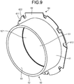
- FIG. 9 is a perspective view illustrating the lens holder according to the first embodiment.
- the lens portion 60 is provided at one end portion of the base member 40.
- the lens portion 60 has the lens 61 and a lens shade 62.
- the lens shade 62 is disposed at one end portion of the base member 40.
- the lens shade 62 is formed from metal material such as aluminum.
- the lens shade 62 may be a light-shielding plate.
- the lens shade 62 has an opening 621 at the center thereof.
- the outer circumference of the lens shade 62 is formed into a shape conforming to the shape of one end portion of the base member 40.
- a recess portion 622 is provided in the outer circumference of the lens shade 62 so as to correspond to the shape of a protruding portion 452 protruding inward from one end portion of the base member 40.
- the protruding portion 452 of the base member 40 is fitted to the recess portion 622, the movement of the lens shade 62 with respect to the base member 40 is restricted.
- Locations on the outer circumference of the lens shade 62 other than the recess portion 622 are also formed into a shape conforming to the shape of one end portion of the base member 40. At each location, when the lens shade 62 contacts the base member 40 in a rotating direction, the movement of the lens shade 62 with respect to the base member 40 is restricted.
- the lens 61 is disposed to overlap the lens shade 62 at one end portion of the base member 40. That is, in the lighting device 1, the lens 61 and the lens shade 62 are disposed in an overlapped manner in this order from the light source portion 30 side. In this manner, the lens shade 62 is disposed so as to overlap the lens 61, and hence the lens 61 can be protected, and the leakage of light from a location other than the opening 621 in the lens shade 62 to the outside of the lighting device 1 can be suppressed.
- the outer circumference of the lens 61 is formed into a shape conforming to the shape of one end portion of the base member 40.
- a recess portion 611 is provided in the outer circumference of the lens 61 so as to correspond to the shape of the protruding portion 452 protruding inward from one end portion of the base member 40.
- the protruding portion 452 of the base member 40 is fitted to the recess portion 611, the movement of the lens 61 with respect to the base member 40 is restricted.
- Two restricting pieces 612 extending in the radial direction are formed on the outer circumference of the lens 61. When the two restricting pieces 612 contact one end portion of the base member 40, the movement of the lens 61 with respect to the base member 40 is restricted.
- the lens holder 50 is provided to overlap the lens portion 60. Specifically, in the lighting device 1, the lens 61, the lens shade 62, and the lens holder 50 are disposed in an overlapped manner in this order from the light source portion 30 side. In this manner, the lens holder 50 supports the lens 61.
- the lens holder 50 may be formed from resin material such as polycarbonate.
- the lens holder 50 is disposed inside the base member 40.
- the lens holder 50 is a cylindrical light distribution member.
- the lens holder 50 is disposed such that one end portion 52 of a base portion 51 formed into a cylindrical shape is along the cover portion 45 of the base member 40.
- the lens holder 50 is disposed such that the other end portion of the base portion 51 is along the peripheral edge of the opening 621 in the lens shade 62.
- the base portion 51 is provided with a colored portion 53 that is provided along the inner peripheral surface thereof and colored in a color that reflects light having a predetermined wavelength.
- the colored portion 53 is provided to overlap the inner peripheral surface of the lens holder 50, that is, the light distribution member.
- the light reflected by the colored portion 53 may be visible light having any wavelength.
- the colored portion 53 may be colored in a color that reflects various kinds of light such as red, yellow, green, and blue.
- the base portion 51 may be formed from a member in a color that absorbs light, that is, black.
- the colored portion 53 maybe a sheet member disposed along the inner peripheral surface of the base portion 51.
- the colored portion 53 may be various kinds of members such as paper and a film colored in a desired color.
- the colored portion 53 may be a sheet-shaped member such as paper and a film rolled into a shape (cylindrical shape) along the inner peripheral surface of the base portion 51.
- the colored portion 53 may be formed by coating the inner peripheral surface of the base portion 51 with a predetermined material.
- the colored portion 53 may be an inner peripheral surface that is coated with paint of a desired color so as to be colored in a color that reflects light having a predetermined wavelength.
- FIG. 10 is a cross-sectional view illustrating a lighting fixture according to the first embodiment.
- the cross-sectional view of the lighting device 1 illustrated in FIG. 10 is a schematic view for illustrating the installation of the lighting device 1 and an illumination range of the lighting device 1.
- the example in FIG. 10 indicates the case where the colored portion 53 is an inner peripheral surface that is coated with paint of a desired color so as to be colored in a color that reflects light having a predetermined wavelength.
- the light source portion 30 emits white light.
- the side where the light source portion 30 (light emitting element 311) faces is the lower side.
- the base member 40 side of the lighting device 1 is the lower side
- the heat sink 20 side is the upper side.
- the lighting device 1 is fixed to a buried hole HL provided in a ceiling CL by the mounting members 25.
- the base member 40 is inserted to the buried hole HL, and the cover portion 45 whose outer diameter is larger than the buried hole HL contacts the ceiling CL from the lower side, so that the upward movement of the lighting device 1 is restricted.
- a person who installs the lighting device 1 inserts the lighting device 1 to the buried hole HL from the heat sink 20 side while pushing and narrowing the mounting members 25.
- the mounting members 25 expand to the original state due to their own biasing forces on the rear side of the ceiling CL, and the mounting members 25 contact the ceiling CL, so that the base member 40 is fitted to the buried hole HL, and the lighting device 1 is installed on the ceiling CL.
- the lighting device 1 is biased upward by the mounting members 25 coupled to the heat sink 20, so that the downward movement due to its own weight is restricted. Specifically, the support portion 263 of the spring portion 26 in the mounting member 25 pushes the ceiling CL downward, so that the lighting device 1 is biased upward. In this manner, the lighting device 1 is fitted to the buried hole HL provided in the ceiling CL, and is installed on the ceiling CL.
- the mounting member 25 when the mounting member 25 is coupled to the heat sink 20, the mounting member 25 is located higher than the position of the buried hole HL in the up-down direction.
- the lighting device 1 enables the buried hole HL to be adjusted to the size (outer diameter) of the base member 40, and can improve design.
- a mounting member is coupled to a member on the side where a light source faces (light extraction direction).
- the mounting member is coupled to a base member.
- the mounting member 25 is coupled to the heat sink 20, and hence the buried hole HL can be adjusted to the size (outer diameter) of the base member 40, and design can be improved.
- the mounting member is coupled to a member (such as base member) formed from resin material.
- the mounting member 25 is coupled to the heat sink 20 formed from metal material such as aluminum, and hence the strength of the mounting of the mounting member 25 can be improved.
- light emitted by the light emitting element 311 in the light source portion 30 is applied to the outside of the lighting device 1 through the frame body 10, the lens portion 60, and the base member 40.
- the distribution of light emitted by the light emitting element 311 and light reflected by the reflection surface 13 of the frame body 10 is controlled by the lens 61 in the lens portion 60, and the light passes through the lens holder 50 disposed in the base member 40 and is applied to the outside of the lighting device 1 from the opening 451 in the cover portion 45.
- the lighting device 1 is a spotlight (pinhole light), and the diameter of the opening 451 in the cover portion 45 is formed to be smaller than the inner diameter of the lens holder 50.
- the light distribution of the lighting device 1 is controlled such that the lighting device 1 illuminates immediately below the ceiling CL on which the lighting device 1 is installed as indicated by an illumination range AR11.
- the inner peripheral surface of a lens holder is colored in a color that absorbs visible light, that is, black.
- the inner peripheral surface of the lens holder absorbs visible light, and does not reflect visible light. Accordingly, when a user sees the conventional lighting device from outside an illumination range of the lighting device, the user does not recognize light emitted from the conventional lighting device.
- the inner peripheral surface of the lens holder absorbs visible light, and hence a user located outside the illumination range of the conventional lighting device does not visually recognize light emitted from the conventional lighting device.
- a user seeing the conventional lighting device from outside the illumination range of the lighting device for example, from an oblique direction, visually recognizes the inside of the lighting device.
- the colored portion 53 is provided on the inner peripheral surface of the lens holder 50.
- the colored portion 53 provided on the inner peripheral surface of the lens holder 50 reflects light of a predetermined color.
- the colored portion 53 of the lens holder 50 reflects light having a wavelength (for example, 620 to 750 nm) corresponding to red.
- the user visually recognizes light of red reflected by the colored portion 53 of the lens holder 50.
- a wavelength for example, 620 to 750 nm
- the user when a user sees the lighting device 1 from a viewpoint VP11, the user recognizes light of red reflected by the colored portion 53 of the lens holder 50. For example, when light of white is emitted from the light source portion 30 and a user sees the lighting device 1 from the viewpoint VP11, the user recognizes a color (for example, pink) obtained by mixing light of red reflected by the colored portion 53 of the lens holder 50 with light of white emitted from the light source portion 30.
- a color for example, pink
- the colored portion 53 provided on the inner peripheral surface of the lens holder 50 reflects predetermined light, and hence a user located outside the illumination range AR11 of the lighting device 1 is allowed to visually recognize desired light.
- the lighting device 1 emits a color (for example, white light) output from the light source portion 30 to the illumination range AR11, and emits light to the outside of the lighting device 1 such that a user located outside the illumination range AR11 visually recognizes desired light.
- a user located in the illumination range AR11 visually recognizes light (for example, white light) illuminating the illumination range AR11, and a user located outside the illumination range AR11 visually recognizes desired light reflected by the colored portion 53.
- the lighting device 1 can change the color recognized by the user depending on a position with respect to the lighting device 1.
- the lighting device 1 can change the color recognized by the user depending on a position at which the user visually recognizes the lighting device 1 such as the viewpoint VP11.
- the lighting device 1, which is a spotlight (pinhole light) uses a large amount of direct light emitted from the light source portion 30 to the outside of the lighting device 1 through the lens portion 60 and the opening 451 in the cover portion 45, and also uses light reflected by the lens holder 50.
- the lighting device is not limited to the lighting device 1 such as a spotlight (pinhole light), and may be various kinds of lighting devices. This matter is described with reference to FIG. 11 to FIG. 18 .
- a lighting device 4 as a downlight is described with reference to the drawings. The same configurations as in the embodiment are denoted by the same reference symbols as in the embodiment, and the descriptions thereof are omitted as appropriate.
- a lighting unit 2 is the same as the lighting unit 2 illustrated in the lighting device 1, and the description thereof is omitted. In this manner, the lighting unit 2 can be used for various kinds of lighting devices such as the lighting device 1 and the lighting device 4.
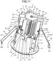
- FIG. 11 and FIG. 12 are perspective views illustrating the lighting device according to the second embodiment. Specifically, FIG. 11 is a perspective view of the lighting device 4 as seen from the side where a heat sink 20 is disposed. FIG. 12 is a perspective view of the lighting device 4 as seen from the side where a light distribution unit 5 is disposed.
- the lighting device 4 has the lighting unit 2 and the light distribution unit 5.
- the lighting unit 2 has a frame body 10, the heat sink 20, and a light source portion 30.
- the configuration of the lighting unit 2 is the same as in the first embodiment, and hence the description thereof is omitted.
- the light distribution unit 5 has a base member 70 as a light distribution member, a lens holder 80 (see FIG. 17 ), and a lens portion 90 (see FIG. 17 ).
- FIG. 13 is a perspective view illustrating a main part of the lighting device according to the second embodiment. Specifically, FIG. 13 is a view illustrating a connection part between the locking portion 12 and a cutout groove 71.
- FIG. 14 is a plan view illustrating a main part of the lighting device according to the second embodiment.
- FIG. 15 is a plan view illustrating a main part of the lighting device according to the second embodiment. Specifically, FIG. 15 is a plan view illustrating the lighting device 4 excluding the lighting unit 2, that is, the light distribution unit 5.
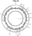
- FIG. 16 is a plan view illustrating a main part of the lighting device according to the second embodiment. Specifically, FIG. 16 is a plan view illustrating the light distribution unit 5 excluding a lens 91.
- FIG. 17 is a perspective view illustrating the lens holder according to the second embodiment.
- each configuration in the base member 70 in the second embodiment corresponds to each configuration in the base member 40 in the first embodiment.
- the base member 70 in the second embodiment corresponds to the base member 40 in the first embodiment, and hence in the base member 70, "4*" in the first embodiment is translated to "7*" for the same points as in the base member 40.
- "*" is any character string (numeral).
- the cutout groove 71 corresponds to the cutout groove 41 in the first embodiment
- a cover portion 75 corresponds to the cover portion 45 in the first embodiment
- an opening 751 corresponds to the opening 451 in the first embodiment.
- each configuration in the lens holder 80 in the second embodiment corresponds to each configuration in the lens holder 50 in the first embodiment.
- the lens holder 80 in the second embodiment corresponds to the lens holder 50 in the first embodiment, and hence in the lens holder 80, "5*" in the first embodiment is translated to "8*" for the same points as in the lens holder 50.
- a base portion 81 corresponds to the base portion 51 in the first embodiment
- a colored portion 83 corresponds to the colored portion 53 in the first embodiment.
- the base portion 81 is provided with the colored portion 83 that is provided along the inner peripheral surface thereof and colored in a color that reflects light having a predetermined wavelength.
- the colored portion 83 is provided to overlap the inner peripheral surface of the lens holder 80, that is, the light distribution member.
- the state in which "the colored portion is provided so as to overlap the inner peripheral surface of the light distribution member" includes both of a configuration in which a colored portion separate from the light distribution member is provided so as to overlap the inner peripheral surface of the light distribution member and a configuration in which the inner peripheral surface itself of the light distribution member is a colored portion.
- each configuration in the lens portion 90 in the second embodiment corresponds to each configuration in the lens portion 60 in the first embodiment.
- the lens portion 90 in the second embodiment corresponds to the lens portion 60 in the first embodiment, and hence in the lens portion 90, "6*" in the first embodiment is translated to "9*" for the same points as in the lens portion 60.
- a lens 91 corresponds to the lens 61 in the first embodiment
- a lens shade 92 corresponds to the lens shade 62 in the first embodiment
- an opening 921 corresponds to the opening 621 in the first embodiment.
- the outer circumference of the lens shade 92 is formed into a shape conforming to the shape of one end portion of the base member 70.
- a recess portion 922 is provided in the outer circumference of the lens shade 92 so as to correspond to the shape of the protruding portion 752 protruding inward from one end portion of the base member 70.
- the base member 70 is provided with two protruding portions 752
- the lens shade 92 is provided with two recess portions 922 corresponding to the protruding portions 752.
- Locations on the outer circumference of the lens shade 92 other than the recess portions 922 are also formed into a shape conforming to the shape of one end portion of the base member 70. At each location, when the lens shade 92 contacts the base member 70 in a rotating direction, the movement of the lens shade 92 with respect to the base member 70 is restricted.
- the outer circumference of the lens 91 is formed into a shape conforming to the shape of one end portion of the base member 70.
- a recess portion 911 is provided in the outer circumference of the lens 91 so as to correspond to the shape of the protruding portion 752 protruding inward from one end portion of the base member 70.
- the lens 91 is provided with two recess portions 911 corresponding to the protruding portions 752.
- Two restricting pieces 912 extending in the radial direction are formed on the outer circumference of the lens 91. When the two restricting pieces 912 contact one end portion of the base member 70, the movement of the lens 91 with respect to the base member 70 is restricted.
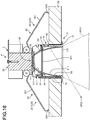
- FIG. 18 is a cross-sectional view illustrating a lighting fixture according to the second embodiment.
- the cross-sectional view of the lighting device 4 illustrated in FIG. 18 is a schematic view for illustrating the installation of the lighting device 4 and an illumination range of the lighting device 4.
- the example in FIG. 18 indicates the case where the colored portion 83 is an inner peripheral surface that is coated with paint of a desired color so as to be colored in a color that reflects light having a predetermined wavelength.
- the example in FIG. 18 indicates the case where the colored portion 83 is provided by coating the surface of an inner peripheral wall 811 of the base portion 81, that is, the inner peripheral surface, with paint of a desired color.
- the example in FIG. 18 indicates the case where the light source portion 30 emits white light.
- the side where the light source portion 30 (light emitting element 311) faces is the lower side.
- the base member 70 side of the lighting device 4 is the lower side
- the heat sink 20 side is the upper side.
- the lighting device 4 is fixed to a buried hole HL provided in a ceiling CL by the mounting members 25.
- the base member 70 is inserted to the buried hole HL, and the cover portion 75 whose outer diameter is larger than the buried hole HL contacts the ceiling CL from the lower side, so that the upward movement of the lighting device 4 is restricted.
- a person who installs the lighting device 4 inserts the lighting device 4 to the buried hole HL from the heat sink 20 side while pushing and narrowing the mounting members 25.
- the mounting members 25 expand to the original state due to their own biasing forces on the rear side of the ceiling CL, and the mounting members 25 contact the ceiling CL, so that the base member 70 is fitted to the buried hole HL, and the lighting device 4 is installed on the ceiling CL.
- the lighting device 4 is biased upward by the mounting members 25 coupled to the heat sink 20, so that the downward movement due to its own weight is restricted. Specifically, the support portion 263 of the spring portion 26 in the mounting member 25 pushes the ceiling CL downward, so that the lighting device 4 is biased upward. In this manner, the lighting device 4 is fitted to the buried hole HL provided in the ceiling CL, and is installed on the ceiling CL.
- the lighting device 4 when the mounting member 25 is coupled to the heat sink 20, the mounting member 25 is located higher than the position of the buried hole HL in the up-down direction.
- the lighting device 4 enables the buried hole HL to be adjusted to the size (outer diameter) of the base member 70, and can improve design.
- light emitted by the light emitting element 311 in the light source portion 30 is applied to the outside of the lighting device 4 through the frame body 10, the lens portion 90, and the base member 70.
- the distribution of light emitted by the light emitting element 311 and light reflected by the reflection surface 13 of the frame body 10 is controlled by the lens 91 in the lens portion 90, and the light passes through the lens holder 80 disposed in the base member 70 and is applied to the outside of the lighting device 4 from the opening 751 in the cover portion 75.
- the lighting device 4 is a downlight, and the diameter of the opening 751 in the cover portion 75 is formed to be substantially the same as the inner diameter of the lens holder 80.
- the light distribution of the lighting device 4 is controlled such that the lighting device 4 illuminates immediately below the ceiling CL on which the lighting device 4 is installed as indicated by an illumination range AR21.
- the inner peripheral surface of a lens holder is a mirror surface, that is, reflects light.
- the inner peripheral surface of the lens holder reflects the inside like a mirror. Accordingly, when a user sees the conventional lighting device from outside an illumination range of the lighting device, the user visually recognizes the structure inside the conventional lighting device. In this manner, a user seeing the conventional lighting device from outside the illumination range of the lighting device, for example, from an oblique direction, visually recognizes the internal structure of the lighting device reflected onto the inner peripheral surface of the lens holder.
- the colored portion 83 is provided on the inner peripheral surface of the lens holder 80.
- the colored portion 83 provided on the inner peripheral surface of the lens holder 80 reflects light of a predetermined color.
- the colored portion 83 of the lens holder 80 reflects light having a wavelength (for example, 620 to 750 nm) corresponding to red.
- the user when a user sees the lighting device 4 from a viewpoint VP21, the user recognizes light of red reflected by the colored portion 83 of the lens holder 80. For example, when light of white is emitted from the light source portion 30 and a user sees the lighting device 1 from the viewpoint VP21, the user recognizes a color (for example, pink) obtained by mixing light of red reflected by the colored portion 83 of the lens holder 80 with light of white emitted from the light source portion 30.
- a color for example, pink
- the colored portion 83 provided on the inner peripheral surface of the lens holder 80 reflects predetermined light, and hence a user located outside the illumination range AR21 of the lighting device 4 is allowed to visually recognize desired light.
- the lighting device 4 emits a color (for example, white light) output from the light source portion 30 to the illumination range AR21, and emits light to the outside of the lighting device 4 such that a user located outside the illumination range AR21 visually recognizes desired light.
- a user located in the illumination range AR21 visually recognizes light (for example, white light) illuminating the illumination range AR21, and a user located outside the illumination range AR21 visually recognizes desired light reflected by the colored portion 83.
- the lighting device 4 can change the color recognized by the user depending on a position with respect to the lighting device 4.
- the lighting device 4 can change the color recognized by the user depending on a position at which the user visually recognizes the lighting device 4 such as the viewpoint VP21.
- the lighting device 4 can prevent the internal structure of the lighting device 4 from being visually recognized by the user.
- the lighting device 4 which is a downlight, uses direct light emitted from the light source portion 30 to the outside of the lighting device 4 through the lens portion 90 and the opening 751 in the cover portion 75, and light reflected by the lens holder 80. In this manner, the lighting device 4 uses a larger amount of light reflected by the lens holder 80 than the lighting device 1. For example, the proportion of the use of light reflected by the lens holder 80 in the lighting device 4 is larger than in the lighting device 1.
- the opening 751 in the cover portion 75 according to the second embodiment is formed to have a diameter larger than that of the opening 451 in the cover portion 45 according to the first embodiment illustrated in FIG. 2 .
- the base member 70 according to the second embodiment is formed to be longer in the axial direction than the base member 40 according to the first embodiment. In other words, the height of the base member 70 in the axial direction is larger than the height of the base member 40 in the axial direction.
- a distance (first length) from the light emitting element 311 in the light source portion 30 to the opening 751 in the cover portion 75 in the lighting device 4 is set longer than a distance (second length) from the light emitting element 311 in the light source portion 30 to the opening 451 in the cover portion 45 in the lighting device 1.
- the lighting device 4 can narrow the range where the light source portion 30 is directly visually recognized through the opening 751. In other words, the lighting device 4 can increase the light-shielding angle as compared with the lighting device 1. Consequently, the lighting device 4 can suppress glare.
- the lighting device 1 and the lighting device 4 may employ various configurations in order to deal with variation in light emitted by the light source portion 30 (light emitting element 311). This matter is described below.
- the current LEDs have large manufacturing variation and variation in color temperature (chromaticity), and hence in order to adjust the color temperature of a fixture (lighting device), the color temperature of an LED is selected or a limited plurality of ranks of LEDs are used.
- the limited ranks of LEDs there may be a case where LEDs cannot be purchased by designating a rank and a case where LEDs have variation even by designating a rank.
- countermeasures for mounting the LEDs at diagonal positions based on color temperatures and narrowing the range of variation are taken, which increases cost and the number of man-hours.
- a member such as the lens portions 60 and 90 may be colored depending on variation in color temperature (chromaticity) of light emitted by the light source portion 30, so that light emitted by the lighting device 1 and the lighting device 4 is adjusted to a desired color temperature.
- an optical member may be colored depending on variation in color temperature (chromaticity) of light emitted by the light source portion 30, so that light emitted by the lighting device 1 and the lighting device 4 is adjusted to a desired color temperature.
- the lenses 61 and 91 may be colored depending on variation in color temperature (chromaticity) of light emitted by the light source portion 30, so that light emitted by the lighting device 1 and the lighting device 4 is adjusted to a desired color temperature.
- a member for protecting an optical member may be colored depending on variation in color temperature (chromaticity) of light emitted by the light source portion 30, so that light emitted by the lighting device 1 and the lighting device 4 is adjusted to a desired color temperature.
- the lens shades 62 and 92 may be colored depending on variation in color temperature (chromaticity) of light emitted by the light source portion 30, so that light emitted by the lighting device 1 and the lighting device 4 is adjusted to a desired color temperature.
- another member in the lighting device 1 and the lighting device 4 may be colored so that light emitted by the lighting device 1 and the lighting device 4 is adjusted to a desired color temperature.
- the lighting unit 2 can be easily replaced even for the light distribution member whose height in the axial direction is different, such as the base member 40 in the first embodiment and the base member 70 in the second embodiment. In this manner, the lighting unit 2 can also be used as the configuration of various types of lighting devices such as a spotlight (pinhole light) and a downlight.
- a spotlight pinhole light
- the light source is not limited to an LED, and may be other light sources such as a krypton bulb.
- the lighting device in which the lighting unit is used is not limited to the spotlight (pinhole light) and the downlight as described above, and may be various types of lighting devices.
Landscapes
- Engineering & Computer Science (AREA)
- General Engineering & Computer Science (AREA)
- Physics & Mathematics (AREA)
- Geometry (AREA)
- Non-Portable Lighting Devices Or Systems Thereof (AREA)
- Securing Globes, Refractors, Reflectors Or The Like (AREA)
Abstract
Description
- The present invention relates to a lighting device.
- Conventionally, various lighting devices whose emitted color changes have been provided. For example, a lighting device in which a layer having a color temperature changing function is provided to the head of a light emitting diode (LED) element has been provided so that the chromaticity changes depending on a location of a light diffuser (such as a shade) serving as a secondary light source. In this case, for example, when an LED light source is turned on, a conical light diffuser becomes a white light secondary light source whose color temperature gradually changes to warm color from the lower part toward the top part.
- Patent Literature 1: Japanese Laid-open Patent Publication No.
2017-092013 - Even for lighting devices such as a downlight and a pinhole light different from the lighting device using a light diffuser serving as a secondary light source as described above, it is desired that the color emitted from the lighting device be changeable to a desired color. The above-mentioned conventional technology, however, is the configuration in which the color of the light diffuser gradually changes, and it is difficult to enable the color to be changed to a desired color depending on the position of a user.
- The present invention has been made in view of the above, and it is an object thereof to provide a lighting device capable of changing a color recognized by a user depending on a position of the user with respect to the lighting device.
- It is an object of the present invention to at least partially solve the problems in the conventional technology. A lighting device to an embodiment includes a light source, a cylindrical light distribution member disposed on a light extraction direction side of the light source and a colored portion provided along an inner peripheral surface of the light distribution member and colored in a color that reflects light having a predetermined wavelength.
- According to one aspect of the present invention, a color recognized by a user can be changed depending on a position of the user with respect to the lighting device.
-
-
FIG. 1 is a perspective view illustrating a lighting device according to a first embodiment. -
FIG. 2 is a perspective view illustrating the lighting device according to the first embodiment. -
FIG. 3 is a perspective view illustrating a lighting unit according to the first embodiment. -
FIG. 4 is a plan view illustrating a main part of the lighting device according to the first embodiment. -
FIG. 5 is a perspective view illustrating a main part of the lighting device according to the first embodiment. -
FIG. 6 is a plan view illustrating a main part of the lighting device according to the first embodiment. -
FIG. 7 is a plan view illustrating a main part of the lighting device according to the first embodiment. -
FIG. 8 is a plan view illustrating a main part of the lighting device according to the first embodiment. -
FIG. 9 is a perspective view illustrating a lens holder according to the first embodiment. -
FIG. 10 is a cross-sectional view illustrating a lighting fixture according to the first embodiment. -
FIG. 11 is a perspective view illustrating a lighting device according to a second embodiment. -
FIG. 12 is a perspective view illustrating the lighting device according to the second embodiment. -
FIG. 13 is a perspective view illustrating a main part of the lighting device according to the second embodiment. -
FIG. 14 is a plan view illustrating a main part of the lighting device according to the second embodiment. -
FIG. 15 is a plan view illustrating a main part of the lighting device according to the second embodiment. -
FIG. 16 is a plan view illustrating a main part of the lighting device according to the second embodiment. -
FIG. 17 is a perspective view illustrating a lens holder according to the second embodiment. -
FIG. 18 is a cross-sectional view illustrating a lighting fixture according to the second embodiment. - In the following first embodiment, a
lighting device 1 as a spotlight (pinhole light) using alighting unit 2 is described with reference to the drawings. The application of the lighting unit is not limited by thelighting device 1 according to the first embodiment described below. The lighting unit is not limited to thelighting device 1, and may be used to any type of available lighting devices depending on the purpose. The drawings are schematic, and it should be noted that the relation in dimensions of elements and the ratios of the elements may be different from the reality. The drawings may have parts where the relation in dimensions or the ratio is different. - First, the outline of the configuration of a
lighting device 1 is described with reference toFIG. 1 to FIG. 3 .FIG. 1 andFIG. 2 are perspective views illustrating a lighting device according to a first embodiment. Specifically,FIG. 1 is a perspective view of thelighting device 1 as seen from the side where aheat sink 20 is disposed.FIG. 2 is a perspective view of thelighting device 1 as seen from the side where alight distribution unit 3 is disposed.FIG. 3 is a perspective view illustrating alighting unit 2 according to the first embodiment. - The
lighting device 1 has thelighting unit 2 and thelight distribution unit 3. Thelighting unit 2 has aframe body 10, theheat sink 20, and alight source portion 30. Thelight distribution unit 3 has abase member 40 as a light distribution member, a lens holder 50 (seeFIG. 9 ), and a lens portion 60 (seeFIG. 9 ). - First, each configuration in the
lighting unit 2 is described. As illustrated inFIG. 3 , theframe body 10 has abase portion 11 having a bottomed cylindrical shape, and alocking portion 12 protruding from the peripheral edge of thebase portion 11 on the opening side. As illustrated inFIG. 1 , theheat sink 20 has arib portion 201, and four fin portions of afirst fin portion 21 to afourth fin portion 24 continuous to therib portion 201. For theheat sink 20, metal material having high thermal conductivity, such as aluminum, is used. - The
first fin portion 21 and thesecond fin portion 22 are provided at positions sandwiching therib portion 201. Thethird fin portion 23 and thefourth fin portion 24 are provided at positions sandwiching therib portion 201.Mounting members 25 are coupled to thethird fin portion 23 and thefourth fin portion 24. The details are described later. - The
light source portion 30 has asubstrate 31 on which alight emitting element 311 is installed on its one surface, and aholding member 32 for holding thesubstrate 31. For example, thelight emitting element 311 is a light emitting diode (LED), and thelight source portion 30 may be a chip on board (COB). For example, theholding member 32 may be a COB holder. - A
bottom portion 111 of thebase portion 11 of theframe body 10 is opened at the center part, and thelight source portion 30 is disposed in the opening in thebottom portion 111. As illustrated inFIG. 3 , thelight source portion 30 is disposed on thebottom portion 111 of thebase portion 11 such that one surface where thelight emitting element 311 is installed faces the opening in thebase portion 11. In the following, the direction from thelight emitting element 311 toward the opening in thebase portion 11 is sometimes referred to as "light extraction direction oflight source portion 30". Thelight emitting element 311 emits visible light (hereinafter sometimes simply referred to as "light"). - The
heat sink 20 is disposed on the outer surface side of thebottom portion 111 of thebase portion 11. For example, therib portion 201 of theheat sink 20 is disposed at a position overlapping the center part of thebottom portion 111. As illustrated inFIG. 3 , a mountingfin 211 of thefirst fin portion 21 is screwed by ascrew member 212 to an insertion hole provided in a mountingportion 112 of thebase portion 11. As illustrated inFIG. 2 , a mountingfin 221 of thesecond fin portion 22 is screwed by ascrew member 222 to an insertion hole provided in the mountingportion 112 of thebase portion 11. In this manner, theheat sink 20 is mounted to theframe body 10. - The
light source portion 30 is mounted to theheat sink 20 in a manner that the holdingmember 32 is screwed to an insertion hole provided in therib portion 201 by a screw member 321 (seeFIG. 6 ). In this manner, thelight source portion 30 and theheat sink 20 are brought into thermal contact with each other. As described above, theheat sink 20 is provided on the rear surface side of thesubstrate 31 in thelight source portion 30, and hence heat from thesubstrate 31 can be efficiently transferred to theheat sink 20 on the rear surface side. - On the
base portion 11, areflection surface 13 is formed as an inclined surface whose diameter increases toward the opening. In this manner, thereflection surface 13 facing the light extraction direction side is formed on thebase portion 11. - The locking
portion 12 is provided on an outer circumference wall of thebase portion 11 at a part where thereflection surface 13 is formed. For example, three lockingportions 12 are provided on the outer circumference wall of thebase portion 11 at equal intervals (for example, intervals of 120°) along the outer circumference. In the example illustrated inFIG. 3 , the three lockingportions 12 are provided on the outer circumference wall of thebase portion 11 at a part where thereflection surface 13 is formed. - A placing
portion 121 extending in the radial direction is provided at the outer peripheral edge of thebase portion 11 on the opening side. For example, the placingportion 121 is provided over the entire circumference of the outer circumference wall of thebase portion 11 along the outer peripheral edge on the opening side. - A
rotation restricting portion 14 is provided on the outer circumference of thebase portion 11 on thebottom portion 111 side. Therotation restricting portion 14 has aninsertion hole 140 used for screwing. For example, threerotation restricting portions 14 are provided on the outer circumference wall of thebase portion 11 at equal intervals (for example, intervals of 120°) along the outer peripheral edge on the opening side. - The coupling of the mounting
member 25 to theheat sink 20 is described. As illustrated inFIG. 3 , mounting members 25-1 and 25-2 are coupled to thethird fin portion 23 and thefourth fin portion 24 of theheat sink 20, respectively. Specifically, the mounting member 25-1 is coupled to thethird fin portion 23, and the mounting member 25-2 is coupled to thefourth fin portion 24. The mounting members 25-1 and 25-2 are referred to as "mountingmembers 25" unless otherwise distinguished. - Referring to
FIG. 4 , the configuration of the mountingmember 25 and the mounting (fixing) of the mountingmember 25 to theheat sink 20 are described.FIG. 4 is a plan view illustrating a main part of the lighting device according to the first embodiment. Specifically,FIG. 4 is a view illustrating a connection part between thethird fin portion 23 of theheat sink 20 and the mounting member 25-1. - The mounting
member 25 has aspring portion 26 and ashaft support portion 27. Thespring portion 26 is formed from elastic material. Thespring portion 26 in thelighting device 1 is a coil spring used to install (mount) thelighting device 1. Thespring portion 26 has a pair ofarm portions 261 extending substantially in parallel to each other with a gap, a pair ofcoil portions 262 continuous to ends of thearm portions 261 on one side, and asupport portion 263 continuous to ends of thearm portion 261 on the other side. Theshaft support portion 27 has abase portion 271 having a cylindrical shape, and a pair ofextended portions 272 extending from both end portions of thebase portion 271 in the axial direction of thebase portion 271. As illustrated inFIG. 4 , theshaft support portion 27 is formed such that the diameter of thebase portion 271 is larger than the inner diameter of thecoil portion 262 and the diameter of theextended portion 272 is smaller than the inner diameter of thecoil portion 262. Thebase portion 271 of theshaft support portion 27 is disposed between the pair ofcoil portions 262 of thespring portion 26, and the pair ofextended portions 272 of theshaft support portion 27 are inserted in the correspondingcoil portions 262. For example, by applying a force to thespring portion 26 in a direction in which the distance between the pair ofcoil portions 262 becomes larger, the gap between the pair ofcoil portions 262 increases, and theshaft support portion 27 may be disposed between the pair ofcoil portions 262. By releasing the force applied to thespring portion 26, the pair ofextended portions 272 may be inserted in the correspondingcoil portions 262. - The
shaft support portion 27 has ashaft rod 273 to be inserted to through holes (not shown), the through hole being formed in thebase portion 271 and the pair ofextended portions 272. The distal end portion of theshaft rod 273 protrudes from one end portion of theextended portion 272. When the distal end portion of theshaft rod 273 is inserted to insertion holes (not shown) provided in each of a pair ofsupport fins 231 of thethird fin portion 23, the mounting member 25-1 is coupled to theheat sink 20.A C ring 274 is mounted to the distal end portion of theshaft rod 273 protruding from thesupport fin 231, and theshaft rod 273 is prevented by theC ring 274 from falling off of the through holes in thebase portion 271 and the pair ofextended portions 272. - When a
distal end portion 264 of thecoil portion 262 is inserted to a regulating hole (an insertion hole) provided in thethird fin portion 23, in thespring portion 26, the rotation of the mounting member 25-1 about theshaft support portion 27 is restricted. Thethird fin portion 23 hasplacement fins 232 between the pair ofsupport fins 231. For example, thethird fin portion 23 has twoplacement fins 232. As illustrated inFIG. 1 , theplacement fins 232 are formed such that the mounting member 25-1 can be disposed between the pair ofsupport fins 231. For example, theplacement fin 232 is formed to be partially cut out such that the mounting member 25-1 can be disposed between the pair ofsupport fins 231. - The mounting
member 25 is also coupled to thefourth fin portion 24 similarly to thethird fin portion 23. As illustrated inFIG. 2 , when the distal end portion of theshaft rod 273 in the mounting member 25-2 is inserted to insertion holes (not shown) provided in a pair ofsupport fins 241 of thefourth fin portion 24, the mounting member 25-2 is coupled to theheat sink 20.A C ring 274 is mounted to the distal end portion of theshaft rod 273 protruding from thesupport fin 241, and theshaft rod 273 is prevented by theC ring 274 from falling off of the through holes in thebase portion 271 and the pair ofextended portions 272. - When the
distal end portion 264 of thecoil portion 262 is inserted to a regulating hole provided in thefourth fin portion 24, in thespring portion 26, the rotation of the mounting member 25-2 about theshaft support portion 27 is restricted. Thefourth fin portion 24 hasplacement fins 242 between the pair ofsupport fins 241. For example, thefourth fin portion 24 has twoplacement fins 242. As illustrated inFIG. 2 , theplacement fins 242 are formed such that the mounting member 25-2 can be disposed between the pair ofsupport fins 241. For example, theplacement fin 232 is formed to be partially cut out such that the mounting member 25-2 can be disposed between the pair ofsupport fins 231. - In this manner, the mounting member 25-1 and the mounting member 25-2 are coupled to the
third fin portion 23 and thefourth fin portion 24, respectively, and provided at positions sandwiching therib portion 201 of theheat sink 20. In other words, in thelighting device 1, the mountingmember 25 is coupled to theheat sink 20 formed from metal material such as aluminum, and hence the strength of the mounting of the mountingmember 25 can be improved. For example, in thelighting device 1, as compared with the case where the mountingmember 25 is mounted to another member than theheat sink 20 in thelighting device 1, such as thebase member 40, the strength of the mounting of the mountingmember 25 can be improved. The installation of thelighting device 1 using the mounting member 25-1 and the mounting member 25-2 is described in detail later. - Next, each configuration in the
light distribution unit 3 is described with reference back toFIG. 1 andFIG. 2 . As illustrated inFIG. 1 , thebase member 40 is formed into a cylindrical shape. The inner diameter of thebase member 40 is larger than the outer diameter of a part of thebase portion 11 of theframe body 10 including the placingportion 121, and smaller than the outer diameter of another part of thebase portion 11 of theframe body 10 including the lockingportion 12. Acutout groove 41 is provided at one end portion of thebase member 40 in the axial direction (hereinafter sometimes simply referred to as "one end portion ofbase member 40"). - At the other end portion of the
base member 40 in the axial direction, acover portion 45 that is formed to have a diameter larger than that of the other end portion and covers the other end portion is provided. Thecover portion 45 is formed into a disc shape, and has anopening 451 formed therein at the center. In this manner, light from thelight source portion 30 is emitted from theopening 451 in thecover portion 45 to the outside of thelighting device 1. - Referring to
FIG. 5 andFIG. 6 , the mounting of thelighting unit 2 and thelight distribution unit 3 is described.FIG. 5 is a perspective view illustrating a main part of the lighting device according to the first embodiment. Specifically,FIG. 5 is a view illustrating a connection part between the lockingportion 12 and thecutout groove 41.FIG. 6 is a plan view illustrating a main part of the lighting device according to the first embodiment. - The
cutout groove 41 has abottom portion 411 and anextended portion 412 extending from thebottom portion 411 to one direction side of the circumferential direction. In the example illustrated inFIG. 6 , thecutout groove 41 has the extendedportion 412 extending from thebottom portion 411 to the clockwise direction side. In the following, the clockwise direction inFIG. 6 is referred to as the "one direction". The width of thebottom portion 411 of thecutout groove 41 is larger than the width of the lockingportion 12 in the circumferential direction, and the lockingportion 12 can be inserted therethrough. The height of theextended portion 412 of thecutout groove 41 is larger than the height of the lockingportion 12 in the axial direction of theframe body 10, and the lockingportion 12 can be inserted therethrough. For example, in the outer circumferential wall of thebase member 40, threecutout grooves 41 are provided at equal intervals (for example, intervals of 120°) along the outer peripheral edge thereof on one end side in the axial direction. In the example illustrated inFIG. 6 , the threecutout grooves 41 are provided at positions corresponding to three lockingportions 12 of theframe body 10, respectively. - For example, in the
base member 40, theframe body 10 is inserted from the opening side while the axes are aligned. Specifically, theframe body 10 is inserted from the opening side into thebase member 40 while the three lockingportions 12 are overlapped at the positions of the threecutout grooves 41 and the axes thereof are aligned. Theframe body 10 is rotated in the one direction in the state in which the lockingportions 12 are inserted into thebase member 40 until reaching the vicinity of thebottom portions 411 of thecorresponding cutout grooves 41. In this manner, the lockingportions 12 of theframe body 10 are disposed in theextended portions 412 of each of thecorresponding cutout grooves 41. As described above, the lockingportions 12 are disposed in theextended portions 412 of thecutout grooves 41, and hence the movement of thebase member 40 with respect to theframe body 10 in the axial direction of thebase member 40 can be restricted. In thelighting device 1, a taperedportion 413 formed near the outer peripheral edge of thecutout groove 41 and a tapered portion 414 (seeFIG. 2 ) formed on theextended portion 412 enable the lockingportion 12 to be more easily guided into thecutout groove 41 and enable the lockingportion 12 to be more easily disposed in theextended portion 412. In the following, the position of theframe body 10 in the state in which the lockingportion 12 is disposed in theextended portion 412 of thecutout groove 41 is sometimes referred to as "fixing position offrame body 10". - At the fixing position of the
frame body 10, thebase member 40 is provided with three insertion holes (not shown) at positions corresponding to each of the insertion holes 140 in the threerotation restricting portions 14. In other words, at the fixing position of theframe body 10, the insertion hole in thebase member 40 and theinsertion hole 140 in therotation restricting portion 14 overlap each other. When ascrew member 141 is screwed and inserted to the insertion hole in thebase member 40 and theinsertion hole 140 in therotation restricting portion 14, thebase member 40 is screwed and mounted to theframe body 10. In this manner, thebase member 40 and theframe body 10 are coupled to each other. The rotation of thebase member 40 about the axis of thebase member 40 with respect to theframe body 10 is restricted. In this manner, thelighting device 1 can suppress the further rotation of thebase member 40 from the fixing position of theframe body 10, and suppress load on the lockingportion 12. - When the
base member 40 is screwed and mounted to theframe body 10, the rotation of thebase member 40 in the one direction is restricted. In this manner, thelighting device 1 can suppress the rotation of thebase member 40 from the fixing position of theframe body 10 to a direction returning to the position before the rotation. Thus, thelighting device 1 can prevent the lockingportion 12 of theframe body 10 from being detached from thecutout groove 41. - As described above, in the
lighting device 1, thebase member 40 is screwed and mounted to theframe body 10 by thescrew member 141. In this manner, when thescrew member 141 is detached, thebase member 40 can rotate with respect to theframe body 10. Thus, a person who installs thelighting device 1 can release the coupling of the lockingportion 12 and thecutout groove 41 by detaching thescrew member 141 and rotating thebase member 40 in the one direction with respect to theframe body 10. Consequently, the person who installs thelighting device 1 can mount various light distribution units to thelighting unit 2. - Referring to
FIG. 7 to FIG. 9 , thelens holder 50 and the like in thelight distribution unit 3 are described.FIG. 7 is a plan view illustrating a main part of the lighting device according to the first embodiment. Specifically,FIG. 7 is a plan view illustrating thelighting device 1 excluding thelighting unit 2, that is, thelight distribution unit 3.FIG. 8 is a plan view illustrating a main part of the lighting device according to the first embodiment. Specifically,FIG. 8 is a plan view illustrating thelight distribution unit 3 excluding alens 61.FIG. 9 is a perspective view illustrating the lens holder according to the first embodiment. - As illustrated in
FIG. 7 , thelens portion 60 is provided at one end portion of thebase member 40. Thelens portion 60 has thelens 61 and alens shade 62. As illustrated inFIG. 8 , thelens shade 62 is disposed at one end portion of thebase member 40. Thelens shade 62 is formed from metal material such as aluminum. Thelens shade 62 may be a light-shielding plate. Thelens shade 62 has anopening 621 at the center thereof. - The outer circumference of the
lens shade 62 is formed into a shape conforming to the shape of one end portion of thebase member 40. For example, arecess portion 622 is provided in the outer circumference of thelens shade 62 so as to correspond to the shape of a protrudingportion 452 protruding inward from one end portion of thebase member 40. When the protrudingportion 452 of thebase member 40 is fitted to therecess portion 622, the movement of thelens shade 62 with respect to thebase member 40 is restricted. Locations on the outer circumference of thelens shade 62 other than therecess portion 622 are also formed into a shape conforming to the shape of one end portion of thebase member 40. At each location, when thelens shade 62 contacts thebase member 40 in a rotating direction, the movement of thelens shade 62 with respect to thebase member 40 is restricted. - As illustrated in
FIG. 7 , thelens 61 is disposed to overlap thelens shade 62 at one end portion of thebase member 40. That is, in thelighting device 1, thelens 61 and thelens shade 62 are disposed in an overlapped manner in this order from thelight source portion 30 side. In this manner, thelens shade 62 is disposed so as to overlap thelens 61, and hence thelens 61 can be protected, and the leakage of light from a location other than theopening 621 in thelens shade 62 to the outside of thelighting device 1 can be suppressed. - The outer circumference of the
lens 61 is formed into a shape conforming to the shape of one end portion of thebase member 40. For example, arecess portion 611 is provided in the outer circumference of thelens 61 so as to correspond to the shape of the protrudingportion 452 protruding inward from one end portion of thebase member 40. When the protrudingportion 452 of thebase member 40 is fitted to therecess portion 611, the movement of thelens 61 with respect to thebase member 40 is restricted. Two restrictingpieces 612 extending in the radial direction are formed on the outer circumference of thelens 61. When the two restrictingpieces 612 contact one end portion of thebase member 40, the movement of thelens 61 with respect to thebase member 40 is restricted. - As illustrated in
FIG. 9 , thelens holder 50 is provided to overlap thelens portion 60. Specifically, in thelighting device 1, thelens 61, thelens shade 62, and thelens holder 50 are disposed in an overlapped manner in this order from thelight source portion 30 side. In this manner, thelens holder 50 supports thelens 61. For example, thelens holder 50 may be formed from resin material such as polycarbonate. - The
lens holder 50 is disposed inside thebase member 40. Thelens holder 50 is a cylindrical light distribution member. Thelens holder 50 is disposed such that oneend portion 52 of abase portion 51 formed into a cylindrical shape is along thecover portion 45 of thebase member 40. Thelens holder 50 is disposed such that the other end portion of thebase portion 51 is along the peripheral edge of theopening 621 in thelens shade 62. - The
base portion 51 is provided with acolored portion 53 that is provided along the inner peripheral surface thereof and colored in a color that reflects light having a predetermined wavelength. In this manner, in thelighting device 1, thecolored portion 53 is provided to overlap the inner peripheral surface of thelens holder 50, that is, the light distribution member. The light reflected by thecolored portion 53 may be visible light having any wavelength. For example, thecolored portion 53 may be colored in a color that reflects various kinds of light such as red, yellow, green, and blue. For example, thebase portion 51 may be formed from a member in a color that absorbs light, that is, black. - For example, the
colored portion 53 maybe a sheet member disposed along the inner peripheral surface of thebase portion 51. For example, thecolored portion 53 may be various kinds of members such as paper and a film colored in a desired color. For example, thecolored portion 53 may be a sheet-shaped member such as paper and a film rolled into a shape (cylindrical shape) along the inner peripheral surface of thebase portion 51. For example, thecolored portion 53 may be formed by coating the inner peripheral surface of thebase portion 51 with a predetermined material. In this case, thecolored portion 53 may be an inner peripheral surface that is coated with paint of a desired color so as to be colored in a color that reflects light having a predetermined wavelength. - Referring to
FIG. 10 , the installation (mounting) of thelighting device 1 and the manner of a color visually recognized by a user due to thecolored portion 53 are described.FIG. 10 is a cross-sectional view illustrating a lighting fixture according to the first embodiment. The cross-sectional view of thelighting device 1 illustrated inFIG. 10 is a schematic view for illustrating the installation of thelighting device 1 and an illumination range of thelighting device 1. - The example in
FIG. 10 indicates the case where thecolored portion 53 is an inner peripheral surface that is coated with paint of a desired color so as to be colored in a color that reflects light having a predetermined wavelength. In the example inFIG. 10 , thelight source portion 30 emits white light. In the example inFIG. 10 , the side where the light source portion 30 (light emitting element 311) faces is the lower side. In other words, thebase member 40 side of thelighting device 1 is the lower side, and theheat sink 20 side is the upper side. - First, the installation of the
lighting device 1 is described. In the example inFIG. 10 , thelighting device 1 is fixed to a buried hole HL provided in a ceiling CL by the mountingmembers 25. Specifically, thebase member 40 is inserted to the buried hole HL, and thecover portion 45 whose outer diameter is larger than the buried hole HL contacts the ceiling CL from the lower side, so that the upward movement of thelighting device 1 is restricted. For example, a person who installs thelighting device 1 inserts thelighting device 1 to the buried hole HL from theheat sink 20 side while pushing and narrowing the mountingmembers 25. After theheat sink 20 is inserted to the buried hole HL, the mountingmembers 25 expand to the original state due to their own biasing forces on the rear side of the ceiling CL, and the mountingmembers 25 contact the ceiling CL, so that thebase member 40 is fitted to the buried hole HL, and thelighting device 1 is installed on the ceiling CL. - In this manner, the
lighting device 1 is biased upward by the mountingmembers 25 coupled to theheat sink 20, so that the downward movement due to its own weight is restricted. Specifically, thesupport portion 263 of thespring portion 26 in the mountingmember 25 pushes the ceiling CL downward, so that thelighting device 1 is biased upward. In this manner, thelighting device 1 is fitted to the buried hole HL provided in the ceiling CL, and is installed on the ceiling CL. In thelighting device 1, when the mountingmember 25 is coupled to theheat sink 20, the mountingmember 25 is located higher than the position of the buried hole HL in the up-down direction. Thus, as compared with the case where the mountingmember 25 is coupled to thebase member 40, thelighting device 1 enables the buried hole HL to be adjusted to the size (outer diameter) of thebase member 40, and can improve design. - In conventional lighting devices, in many cases, a mounting member is coupled to a member on the side where a light source faces (light extraction direction). For example, in the conventional lighting devices, in many cases, the mounting member is coupled to a base member. In such cases, it is difficult to adjust the size (outer diameter) of a buried hole in which a lighting device is to be installed to the outer diameter of the base member due to the constraints of the placement of the mounting member. Thus, in the conventional lighting devices, there is a problem in that it is difficult to decrease the size (outer diameter) of a buried hole in which a lighting device is to be installed, and it is difficult to improve design. On the other hand, in the
lighting device 1, as described above, the mountingmember 25 is coupled to theheat sink 20, and hence the buried hole HL can be adjusted to the size (outer diameter) of thebase member 40, and design can be improved. In the conventional lighting devices, in many cases, the mounting member is coupled to a member (such as base member) formed from resin material. Thus, in the conventional lighting devices, there is a problem in that it is difficult to improve the strength of the mounting of the mounting member due to the constraints of the member formed from resin material. On the other hand, in thelighting device 1, the mountingmember 25 is coupled to theheat sink 20 formed from metal material such as aluminum, and hence the strength of the mounting of the mountingmember 25 can be improved. - In the
lighting device 1, light emitted by thelight emitting element 311 in thelight source portion 30 is applied to the outside of thelighting device 1 through theframe body 10, thelens portion 60, and thebase member 40. Specifically, the distribution of light emitted by thelight emitting element 311 and light reflected by thereflection surface 13 of theframe body 10 is controlled by thelens 61 in thelens portion 60, and the light passes through thelens holder 50 disposed in thebase member 40 and is applied to the outside of thelighting device 1 from theopening 451 in thecover portion 45. - As illustrated in
FIG. 10 , thelighting device 1 is a spotlight (pinhole light), and the diameter of theopening 451 in thecover portion 45 is formed to be smaller than the inner diameter of thelens holder 50. Thus, the light distribution of thelighting device 1 is controlled such that thelighting device 1 illuminates immediately below the ceiling CL on which thelighting device 1 is installed as indicated by an illumination range AR11. - For example, in a conventional lighting device as a spotlight (pinhole light), the inner peripheral surface of a lens holder (light distribution member) is colored in a color that absorbs visible light, that is, black. Thus, in the conventional lighting device, the inner peripheral surface of the lens holder absorbs visible light, and does not reflect visible light. Accordingly, when a user sees the conventional lighting device from outside an illumination range of the lighting device, the user does not recognize light emitted from the conventional lighting device. In this manner, in the conventional lighting device, the inner peripheral surface of the lens holder absorbs visible light, and hence a user located outside the illumination range of the conventional lighting device does not visually recognize light emitted from the conventional lighting device. A user seeing the conventional lighting device from outside the illumination range of the lighting device, for example, from an oblique direction, visually recognizes the inside of the lighting device.
- On the other hand, in the
lighting device 1, thecolored portion 53 is provided on the inner peripheral surface of thelens holder 50. Thus, in thelighting device 1, thecolored portion 53 provided on the inner peripheral surface of thelens holder 50 reflects light of a predetermined color. For example, when thecolored portion 53 is red, in thelighting device 1, thecolored portion 53 of thelens holder 50 reflects light having a wavelength (for example, 620 to 750 nm) corresponding to red. Thus, when a user sees thelighting device 1 from outside the illumination range AR11 of thelighting device 1, the user visually recognizes light of red reflected by thecolored portion 53 of thelens holder 50. In the example inFIG. 10 , when a user sees thelighting device 1 from a viewpoint VP11, the user recognizes light of red reflected by thecolored portion 53 of thelens holder 50. For example, when light of white is emitted from thelight source portion 30 and a user sees thelighting device 1 from the viewpoint VP11, the user recognizes a color (for example, pink) obtained by mixing light of red reflected by thecolored portion 53 of thelens holder 50 with light of white emitted from thelight source portion 30. - As described above, in the
lighting device 1, thecolored portion 53 provided on the inner peripheral surface of thelens holder 50 reflects predetermined light, and hence a user located outside the illumination range AR11 of thelighting device 1 is allowed to visually recognize desired light. In other words, thelighting device 1 emits a color (for example, white light) output from thelight source portion 30 to the illumination range AR11, and emits light to the outside of thelighting device 1 such that a user located outside the illumination range AR11 visually recognizes desired light. In this manner, a user located in the illumination range AR11 visually recognizes light (for example, white light) illuminating the illumination range AR11, and a user located outside the illumination range AR11 visually recognizes desired light reflected by thecolored portion 53. Thus, thelighting device 1 can change the color recognized by the user depending on a position with respect to thelighting device 1. For example, thelighting device 1 can change the color recognized by the user depending on a position at which the user visually recognizes thelighting device 1 such as the viewpoint VP11. Thelighting device 1, which is a spotlight (pinhole light), uses a large amount of direct light emitted from thelight source portion 30 to the outside of thelighting device 1 through thelens portion 60 and theopening 451 in thecover portion 45, and also uses light reflected by thelens holder 50. - The lighting device is not limited to the
lighting device 1 such as a spotlight (pinhole light), and may be various kinds of lighting devices. This matter is described with reference toFIG. 11 to FIG. 18 . In the following second embodiment, alighting device 4 as a downlight is described with reference to the drawings. The same configurations as in the embodiment are denoted by the same reference symbols as in the embodiment, and the descriptions thereof are omitted as appropriate. For example, alighting unit 2 is the same as thelighting unit 2 illustrated in thelighting device 1, and the description thereof is omitted. In this manner, thelighting unit 2 can be used for various kinds of lighting devices such as thelighting device 1 and thelighting device 4. - First, the outline of the configuration of the
lighting device 4 is described with reference toFIG. 11 andFIG. 12 .FIG. 11 andFIG. 12 are perspective views illustrating the lighting device according to the second embodiment. Specifically,FIG. 11 is a perspective view of thelighting device 4 as seen from the side where aheat sink 20 is disposed.FIG. 12 is a perspective view of thelighting device 4 as seen from the side where alight distribution unit 5 is disposed. - The
lighting device 4 has thelighting unit 2 and thelight distribution unit 5. Thelighting unit 2 has aframe body 10, theheat sink 20, and alight source portion 30. The configuration of thelighting unit 2 is the same as in the first embodiment, and hence the description thereof is omitted. Thelight distribution unit 5 has abase member 70 as a light distribution member, a lens holder 80 (seeFIG. 17 ), and a lens portion 90 (seeFIG. 17 ). - Referring to
FIG. 13 to FIG. 17 , each configuration in thelight distribution unit 5 is described.FIG. 13 is a perspective view illustrating a main part of the lighting device according to the second embodiment. Specifically,FIG. 13 is a view illustrating a connection part between the lockingportion 12 and acutout groove 71.FIG. 14 is a plan view illustrating a main part of the lighting device according to the second embodiment.FIG. 15 is a plan view illustrating a main part of the lighting device according to the second embodiment. Specifically,FIG. 15 is a plan view illustrating thelighting device 4 excluding thelighting unit 2, that is, thelight distribution unit 5.FIG. 16 is a plan view illustrating a main part of the lighting device according to the second embodiment. Specifically,FIG. 16 is a plan view illustrating thelight distribution unit 5 excluding alens 91.FIG. 17 is a perspective view illustrating the lens holder according to the second embodiment. - The same configurations as in the first embodiment are denoted by the same reference symbols as in the first embodiment, and the descriptions thereof are omitted as appropriate. That is, in the second embodiment, the descriptions of configurations corresponding to the configurations in the first embodiment are omitted as appropriate, and the differences from the first embodiment are described below.
- For example, each configuration in the
base member 70 in the second embodiment corresponds to each configuration in thebase member 40 in the first embodiment. In this manner, thebase member 70 in the second embodiment corresponds to thebase member 40 in the first embodiment, and hence in thebase member 70, "4*" in the first embodiment is translated to "7*" for the same points as in thebase member 40. "*" is any character string (numeral). For example, thecutout groove 71 corresponds to thecutout groove 41 in the first embodiment, acover portion 75 corresponds to thecover portion 45 in the first embodiment, and anopening 751 corresponds to theopening 451 in the first embodiment. - For example, each configuration in the
lens holder 80 in the second embodiment corresponds to each configuration in thelens holder 50 in the first embodiment. In this manner, thelens holder 80 in the second embodiment corresponds to thelens holder 50 in the first embodiment, and hence in thelens holder 80, "5*" in the first embodiment is translated to "8*" for the same points as in thelens holder 50. For example, abase portion 81 corresponds to thebase portion 51 in the first embodiment, and acolored portion 83 corresponds to thecolored portion 53 in the first embodiment. For example, thebase portion 81 is provided with thecolored portion 83 that is provided along the inner peripheral surface thereof and colored in a color that reflects light having a predetermined wavelength. In this manner, in thelighting device 4, thecolored portion 83 is provided to overlap the inner peripheral surface of thelens holder 80, that is, the light distribution member. The state in which "the colored portion is provided so as to overlap the inner peripheral surface of the light distribution member" includes both of a configuration in which a colored portion separate from the light distribution member is provided so as to overlap the inner peripheral surface of the light distribution member and a configuration in which the inner peripheral surface itself of the light distribution member is a colored portion. - For example, each configuration in the
lens portion 90 in the second embodiment corresponds to each configuration in thelens portion 60 in the first embodiment. In this manner, thelens portion 90 in the second embodiment corresponds to thelens portion 60 in the first embodiment, and hence in thelens portion 90, "6*" in the first embodiment is translated to "9*" for the same points as in thelens portion 60. For example, alens 91 corresponds to thelens 61 in the first embodiment, alens shade 92 corresponds to thelens shade 62 in the first embodiment, and anopening 921 corresponds to theopening 621 in the first embodiment. - The outer circumference of the
lens shade 92 is formed into a shape conforming to the shape of one end portion of thebase member 70. For example, arecess portion 922 is provided in the outer circumference of thelens shade 92 so as to correspond to the shape of the protrudingportion 752 protruding inward from one end portion of thebase member 70. As illustrated inFIG. 16 , thebase member 70 is provided with two protrudingportions 752, and thelens shade 92 is provided with tworecess portions 922 corresponding to the protrudingportions 752. When a corresponding protrudingportion 752 of thebase member 70 is fitted to therecess portion 922, the movement of thelens shade 92 with respect to thebase member 70 is restricted. Locations on the outer circumference of thelens shade 92 other than therecess portions 922 are also formed into a shape conforming to the shape of one end portion of thebase member 70. At each location, when thelens shade 92 contacts thebase member 70 in a rotating direction, the movement of thelens shade 92 with respect to thebase member 70 is restricted. - The outer circumference of the
lens 91 is formed into a shape conforming to the shape of one end portion of thebase member 70. For example, arecess portion 911 is provided in the outer circumference of thelens 91 so as to correspond to the shape of the protrudingportion 752 protruding inward from one end portion of thebase member 70. As illustrated inFIG. 15 , thelens 91 is provided with tworecess portions 911 corresponding to the protrudingportions 752. When a corresponding protrudingportion 752 of thebase member 70 is fitted to therecess portion 911, the movement of thelens 91 with respect to thebase member 70 is restricted. Two restrictingpieces 912 extending in the radial direction are formed on the outer circumference of thelens 91. When the two restrictingpieces 912 contact one end portion of thebase member 70, the movement of thelens 91 with respect to thebase member 70 is restricted. - Referring to
FIG. 18 , the installation (mounting) of thelighting device 4 and the manner of a color visually recognized by a user due to thecolored portion 83 are described.FIG. 18 is a cross-sectional view illustrating a lighting fixture according to the second embodiment. The cross-sectional view of thelighting device 4 illustrated inFIG. 18 is a schematic view for illustrating the installation of thelighting device 4 and an illumination range of thelighting device 4. - The example in
FIG. 18 indicates the case where thecolored portion 83 is an inner peripheral surface that is coated with paint of a desired color so as to be colored in a color that reflects light having a predetermined wavelength. Specifically, the example inFIG. 18 indicates the case where thecolored portion 83 is provided by coating the surface of an innerperipheral wall 811 of thebase portion 81, that is, the inner peripheral surface, with paint of a desired color. The example inFIG. 18 indicates the case where thelight source portion 30 emits white light. In the example inFIG. 18 , the side where the light source portion 30 (light emitting element 311) faces is the lower side. In other words, thebase member 70 side of thelighting device 4 is the lower side, and theheat sink 20 side is the upper side. - First, the installation of the
lighting device 4 is described. In the example inFIG. 18 , thelighting device 4 is fixed to a buried hole HL provided in a ceiling CL by the mountingmembers 25. Specifically, thebase member 70 is inserted to the buried hole HL, and thecover portion 75 whose outer diameter is larger than the buried hole HL contacts the ceiling CL from the lower side, so that the upward movement of thelighting device 4 is restricted. For example, a person who installs thelighting device 4 inserts thelighting device 4 to the buried hole HL from theheat sink 20 side while pushing and narrowing the mountingmembers 25. After theheat sink 20 is inserted to the buried hole HL, the mountingmembers 25 expand to the original state due to their own biasing forces on the rear side of the ceiling CL, and the mountingmembers 25 contact the ceiling CL, so that thebase member 70 is fitted to the buried hole HL, and thelighting device 4 is installed on the ceiling CL. - In this manner, the
lighting device 4 is biased upward by the mountingmembers 25 coupled to theheat sink 20, so that the downward movement due to its own weight is restricted. Specifically, thesupport portion 263 of thespring portion 26 in the mountingmember 25 pushes the ceiling CL downward, so that thelighting device 4 is biased upward. In this manner, thelighting device 4 is fitted to the buried hole HL provided in the ceiling CL, and is installed on the ceiling CL. In thelighting device 4, when the mountingmember 25 is coupled to theheat sink 20, the mountingmember 25 is located higher than the position of the buried hole HL in the up-down direction. Thus, as compared with the case where the mountingmember 25 is coupled to thebase member 70, thelighting device 4 enables the buried hole HL to be adjusted to the size (outer diameter) of thebase member 70, and can improve design. - In the
lighting device 4, light emitted by thelight emitting element 311 in thelight source portion 30 is applied to the outside of thelighting device 4 through theframe body 10, thelens portion 90, and thebase member 70. Specifically, the distribution of light emitted by thelight emitting element 311 and light reflected by thereflection surface 13 of theframe body 10 is controlled by thelens 91 in thelens portion 90, and the light passes through thelens holder 80 disposed in thebase member 70 and is applied to the outside of thelighting device 4 from theopening 751 in thecover portion 75. - As illustrated in
FIG. 18 , thelighting device 4 is a downlight, and the diameter of theopening 751 in thecover portion 75 is formed to be substantially the same as the inner diameter of thelens holder 80. Thus, the light distribution of thelighting device 4 is controlled such that thelighting device 4 illuminates immediately below the ceiling CL on which thelighting device 4 is installed as indicated by an illumination range AR21. - For example, in a conventional lighting device as a downlight similar to the
lighting device 4, the inner peripheral surface of a lens holder (light distribution member) is a mirror surface, that is, reflects light. Thus, in the conventional lighting device, the inner peripheral surface of the lens holder reflects the inside like a mirror. Accordingly, when a user sees the conventional lighting device from outside an illumination range of the lighting device, the user visually recognizes the structure inside the conventional lighting device. In this manner, a user seeing the conventional lighting device from outside the illumination range of the lighting device, for example, from an oblique direction, visually recognizes the internal structure of the lighting device reflected onto the inner peripheral surface of the lens holder. - On the other hand, in the
lighting device 4, thecolored portion 83 is provided on the inner peripheral surface of thelens holder 80. Thus, in thelighting device 4, thecolored portion 83 provided on the inner peripheral surface of thelens holder 80 reflects light of a predetermined color. For example, when thecolored portion 83 is red, in thelighting device 4, thecolored portion 83 of thelens holder 80 reflects light having a wavelength (for example, 620 to 750 nm) corresponding to red. Thus, when a user sees thelighting device 4 from outside the illumination range AR21 of thelighting device 4, the user visually recognizes light of red reflected by thecolored portion 83 of thelens holder 80. In the example inFIG. 18 , when a user sees thelighting device 4 from a viewpoint VP21, the user recognizes light of red reflected by thecolored portion 83 of thelens holder 80. For example, when light of white is emitted from thelight source portion 30 and a user sees thelighting device 1 from the viewpoint VP21, the user recognizes a color (for example, pink) obtained by mixing light of red reflected by thecolored portion 83 of thelens holder 80 with light of white emitted from thelight source portion 30. - As described above, in the
lighting device 4, thecolored portion 83 provided on the inner peripheral surface of thelens holder 80 reflects predetermined light, and hence a user located outside the illumination range AR21 of thelighting device 4 is allowed to visually recognize desired light. In other words, thelighting device 4 emits a color (for example, white light) output from thelight source portion 30 to the illumination range AR21, and emits light to the outside of thelighting device 4 such that a user located outside the illumination range AR21 visually recognizes desired light. In this manner, a user located in the illumination range AR21 visually recognizes light (for example, white light) illuminating the illumination range AR21, and a user located outside the illumination range AR21 visually recognizes desired light reflected by thecolored portion 83. Thus, thelighting device 4 can change the color recognized by the user depending on a position with respect to thelighting device 4. For example, thelighting device 4 can change the color recognized by the user depending on a position at which the user visually recognizes thelighting device 4 such as the viewpoint VP21. When the user sees thelighting device 4 from outside the illumination range AR21, thelighting device 4 can prevent the internal structure of thelighting device 4 from being visually recognized by the user. - The
lighting device 4, which is a downlight, uses direct light emitted from thelight source portion 30 to the outside of thelighting device 4 through thelens portion 90 and theopening 751 in thecover portion 75, and light reflected by thelens holder 80. In this manner, thelighting device 4 uses a larger amount of light reflected by thelens holder 80 than thelighting device 1. For example, the proportion of the use of light reflected by thelens holder 80 in thelighting device 4 is larger than in thelighting device 1. - As illustrated in
FIG. 18 , theopening 751 in thecover portion 75 according to the second embodiment is formed to have a diameter larger than that of theopening 451 in thecover portion 45 according to the first embodiment illustrated inFIG. 2 . In this case, glare caused when thelight emitting element 311 in thelight source portion 30 is directly visually recognized occurs more easily in thelighting device 4 using thebase member 70 than thelighting device 1 using thebase member 40. Thus, thebase member 70 according to the second embodiment is formed to be longer in the axial direction than thebase member 40 according to the first embodiment. In other words, the height of thebase member 70 in the axial direction is larger than the height of thebase member 40 in the axial direction. - In this manner, a distance (first length) from the
light emitting element 311 in thelight source portion 30 to theopening 751 in thecover portion 75 in thelighting device 4 is set longer than a distance (second length) from thelight emitting element 311 in thelight source portion 30 to theopening 451 in thecover portion 45 in thelighting device 1. Thus, as compared with the case where the distance from thelight emitting element 311 in thelight source portion 30 to theopening 751 in thecover portion 75 is the second length, thelighting device 4 can narrow the range where thelight source portion 30 is directly visually recognized through theopening 751. In other words, thelighting device 4 can increase the light-shielding angle as compared with thelighting device 1. Consequently, thelighting device 4 can suppress glare. - The
lighting device 1 and thelighting device 4 may employ various configurations in order to deal with variation in light emitted by the light source portion 30 (light emitting element 311). This matter is described below. - For example, the current LEDs (light emitting elements) have large manufacturing variation and variation in color temperature (chromaticity), and hence in order to adjust the color temperature of a fixture (lighting device), the color temperature of an LED is selected or a limited plurality of ranks of LEDs are used. Regarding the limited ranks of LEDs, there may be a case where LEDs cannot be purchased by designating a rank and a case where LEDs have variation even by designating a rank. In the case where such LEDs are mounted, for example, countermeasures for mounting the LEDs at diagonal positions based on color temperatures and narrowing the range of variation are taken, which increases cost and the number of man-hours.
- Thus, in the
lighting device 1 and thelighting device 4, a member such as thelens portions light source portion 30, so that light emitted by thelighting device 1 and thelighting device 4 is adjusted to a desired color temperature. - For example, in the
lighting device 1 and thelighting device 4, an optical member may be colored depending on variation in color temperature (chromaticity) of light emitted by thelight source portion 30, so that light emitted by thelighting device 1 and thelighting device 4 is adjusted to a desired color temperature. For example, in thelighting device 1 and thelighting device 4, thelenses light source portion 30, so that light emitted by thelighting device 1 and thelighting device 4 is adjusted to a desired color temperature. - For example, in the
lighting device 1 and thelighting device 4, a member for protecting an optical member may be colored depending on variation in color temperature (chromaticity) of light emitted by thelight source portion 30, so that light emitted by thelighting device 1 and thelighting device 4 is adjusted to a desired color temperature. For example, in thelighting device 1 and thelighting device 4, the lens shades 62 and 92 may be colored depending on variation in color temperature (chromaticity) of light emitted by thelight source portion 30, so that light emitted by thelighting device 1 and thelighting device 4 is adjusted to a desired color temperature. The above is an example, and another member in thelighting device 1 and thelighting device 4 may be colored so that light emitted by thelighting device 1 and thelighting device 4 is adjusted to a desired color temperature. - As described above, the
lighting unit 2 can be easily replaced even for the light distribution member whose height in the axial direction is different, such as thebase member 40 in the first embodiment and thebase member 70 in the second embodiment. In this manner, thelighting unit 2 can also be used as the configuration of various types of lighting devices such as a spotlight (pinhole light) and a downlight. - In the first embodiment and the second embodiment, the light source is not limited to an LED, and may be other light sources such as a krypton bulb. The lighting device in which the lighting unit is used is not limited to the spotlight (pinhole light) and the downlight as described above, and may be various types of lighting devices.
-
- 1 lighting device
- 2 lighting unit
- 10 frame body
- 11 base portion
- 12 locking portion
- 121 placing portion
- 13 reflection surface
- 14 rotation restricting portion
- 140 insertion hole
- 20 heat sink
- 25 mounting member
- 30 light source portion
- 3 light distribution unit
- 40 base member
- 41 cutout groove
- 411 bottom portion
- 412 extended portion
- 45 cover portion
- 50 lens holder (light distribution member)
- 53 colored portion
- 60 lens portion
- 4 lighting device
- 5 light distribution unit
- 70 base member
- 71 cutout groove
- 711 bottom portion
- 712 extended portion
- 75 cover portion
- 80 lens holder (light distribution member)
- 83 colored portion
- 90 lens portion
Claims (12)
- A lighting device, comprising:a light source;a cylindrical light distribution member disposed on a light extraction direction side of the light source; anda colored portion provided along an inner peripheral surface of the light distribution member and colored in a color that reflects light having a predetermined wavelength.
- The lighting device according to claim 1, wherein the colored portion is a sheet member disposed along the inner peripheral surface.
- The lighting device according to claim 1, wherein the colored portion is formed by coating the inner peripheral surface with a predetermined material.
- The lighting device according to any one of claims 1 to 3, wherein
the inner peripheral surface of the light distribution member is a surface that absorbs light, and
the colored portion is provided to overlap the inner peripheral surface of the light distribution member. - The lighting device according to any one of claims 1 to 3, wherein
the inner peripheral surface of the light distribution member is a surface that reflects light, and
the colored portion is provided to overlap the inner peripheral surface of the light distribution member. - The lighting device according to any one of claims 1 to 5, further comprising:a heat sink disposed on a rear surface side of the light source; anda mounting member fixed to the heat sink and used to mount the lighting device.
- The lighting device according to claim 6, wherein the mounting member is a coil spring.
- The lighting device according to any one of claims 1 to 7, further comprising:a frame body in which an opening faced by the light source is formed at one end portion, the light distribution member being disposed on the one end portion side, and a heat sink being disposed on the other end portion side, anda locking portion that is a protrusion protruding from an outer circumference wall of the frame body, the locking portion being disposed to overlap the outer circumference wall of the frame body and configured to lock a base member extending to a light extraction direction side of the light source.
- The lighting device according to claim 8, wherein the frame body has a reflection surface formed thereon, the reflection surface facing the light extraction direction side of the light source.
- The lighting device according to claim 8 or 9, wherein the locking portion is disposed in an extended portion extending to the one direction side of a circumferential direction from a bottom portion of a cutout groove that is provided at one end portion of the base member having a cylindrical shape through which the frame body is insertable, to restrict movement of the base member in an axial direction of the base member.
- The lighting device according to claim 10, wherein a plurality of the locking portions are provided along the outer circumference of the frame body, and the locking portions are disposed in the extended portions of a plurality of the cutout grooves provided in the base member, respectively, to restrict the movement of the base member in the axial direction of the base member.
- The lighting device according to any one of claims 1 to 11, further comprising a lens disposed between the light source and the light distribution member, wherein
the light distribution member is a lens holder for supporting the lens.
Applications Claiming Priority (2)
| Application Number | Priority Date | Filing Date | Title |
|---|---|---|---|
| JP2017191060A JP2019067605A (en) | 2017-09-29 | 2017-09-29 | Lighting device |
| PCT/JP2018/035157 WO2019065528A1 (en) | 2017-09-29 | 2018-09-21 | Lighting device |
Publications (2)
| Publication Number | Publication Date |
|---|---|
| EP3690307A1 true EP3690307A1 (en) | 2020-08-05 |
| EP3690307A4 EP3690307A4 (en) | 2021-05-26 |
Family
ID=65902849
Family Applications (1)
| Application Number | Title | Priority Date | Filing Date |
|---|---|---|---|
| EP18860728.7A Withdrawn EP3690307A4 (en) | 2017-09-29 | 2018-09-21 | Lighting device |
Country Status (3)
| Country | Link |
|---|---|
| EP (1) | EP3690307A4 (en) |
| JP (1) | JP2019067605A (en) |
| WO (1) | WO2019065528A1 (en) |
Families Citing this family (1)
| Publication number | Priority date | Publication date | Assignee | Title |
|---|---|---|---|---|
| CN110285362B (en) * | 2019-08-12 | 2021-11-02 | 中山市冠华照明灯饰有限公司 | LED down lamp |
Family Cites Families (7)
| Publication number | Priority date | Publication date | Assignee | Title |
|---|---|---|---|---|
| US7014341B2 (en) * | 2003-10-02 | 2006-03-21 | Acuity Brands, Inc. | Decorative luminaires |
| JP2008147044A (en) * | 2006-12-11 | 2008-06-26 | Ushio Spex Inc | Unit type downlight adapter |
| JP5499493B2 (en) * | 2009-03-05 | 2014-05-21 | 東芝ライテック株式会社 | lighting equipment |
| JP5729600B2 (en) * | 2011-03-25 | 2015-06-03 | 東芝ライテック株式会社 | lighting equipment |
| JP6238199B2 (en) * | 2013-11-05 | 2017-11-29 | パナソニックIpマネジメント株式会社 | lighting equipment |
| CN204693101U (en) * | 2015-05-22 | 2015-10-07 | 潘能红 | The LED of the convertible color that a kind of illumination is concentrated |
| JP2017092013A (en) | 2015-11-02 | 2017-05-25 | 株式会社トレンタ | Lighting device |
-
2017
- 2017-09-29 JP JP2017191060A patent/JP2019067605A/en active Pending
-
2018
- 2018-09-21 EP EP18860728.7A patent/EP3690307A4/en not_active Withdrawn
- 2018-09-21 WO PCT/JP2018/035157 patent/WO2019065528A1/en not_active Ceased
Also Published As
| Publication number | Publication date |
|---|---|
| WO2019065528A1 (en) | 2019-04-04 |
| EP3690307A4 (en) | 2021-05-26 |
| JP2019067605A (en) | 2019-04-25 |
Similar Documents
| Publication | Publication Date | Title |
|---|---|---|
| CN102282412B (en) | Illuminating apparatus | |
| US9291319B2 (en) | Reflectors and reflector orientation feature to prevent non-qualified trim | |
| EP2729731B1 (en) | Lens and trim attachment structure for solid state downlights | |
| KR20100017616A (en) | Light fixtures and lighting devices | |
| CA2862702C (en) | Optical system and lighting device comprised thereof | |
| JP6257295B2 (en) | LED lighting device | |
| JP5977538B2 (en) | Unit type downlight | |
| JP6241611B2 (en) | Lamp device and lighting device | |
| JP5793270B1 (en) | Auxiliary parts for mounting and lighting device | |
| JP7061507B2 (en) | lighting equipment | |
| EP4004440B1 (en) | Dual distribution lens for a luminaire | |
| JP7304520B2 (en) | lighting equipment | |
| WO2019065528A1 (en) | Lighting device | |
| WO2015133196A1 (en) | Lighting device and led light source unit | |
| JP6639598B2 (en) | Lighting equipment | |
| JP7054608B2 (en) | Lighting unit and lighting equipment | |
| JP6407700B2 (en) | lighting equipment | |
| CN211875813U (en) | Ceiling lamp | |
| CN220471434U (en) | Lamp cap and lamp | |
| JP2019192377A (en) | Lighting device | |
| JP6990149B2 (en) | lighting equipment | |
| JP2026029283A (en) | LED lamp | |
| JP2026029280A (en) | lighting fixtures | |
| KR20260030917A (en) | Compact LED retrofit and adjustable centering ring | |
| WO2025154633A1 (en) | Led lamp |
Legal Events
| Date | Code | Title | Description |
|---|---|---|---|
| STAA | Information on the status of an ep patent application or granted ep patent |
Free format text: STATUS: THE INTERNATIONAL PUBLICATION HAS BEEN MADE |
|
| PUAI | Public reference made under article 153(3) epc to a published international application that has entered the european phase |
Free format text: ORIGINAL CODE: 0009012 |
|
| STAA | Information on the status of an ep patent application or granted ep patent |
Free format text: STATUS: REQUEST FOR EXAMINATION WAS MADE |
|
| 17P | Request for examination filed |
Effective date: 20200421 |
|
| AK | Designated contracting states |
Kind code of ref document: A1 Designated state(s): AL AT BE BG CH CY CZ DE DK EE ES FI FR GB GR HR HU IE IS IT LI LT LU LV MC MK MT NL NO PL PT RO RS SE SI SK SM TR |
|
| AX | Request for extension of the european patent |
Extension state: BA ME |
|
| DAV | Request for validation of the european patent (deleted) | ||
| DAX | Request for extension of the european patent (deleted) | ||
| A4 | Supplementary search report drawn up and despatched |
Effective date: 20210429 |
|
| RIC1 | Information provided on ipc code assigned before grant |
Ipc: F21S 8/02 20060101AFI20210422BHEP Ipc: F21V 7/00 20060101ALI20210422BHEP Ipc: F21V 7/22 20180101ALI20210422BHEP Ipc: F21V 21/04 20060101ALI20210422BHEP Ipc: F21V 29/503 20150101ALI20210422BHEP Ipc: F21V 29/77 20150101ALI20210422BHEP Ipc: F21Y 101/00 20160101ALI20210422BHEP Ipc: F21Y 115/10 20160101ALI20210422BHEP Ipc: F21V 7/04 20060101ALI20210422BHEP Ipc: F21V 29/75 20150101ALI20210422BHEP |
|
| STAA | Information on the status of an ep patent application or granted ep patent |
Free format text: STATUS: THE APPLICATION IS DEEMED TO BE WITHDRAWN |
|
| 18D | Application deemed to be withdrawn |
Effective date: 20211130 |