EP3690257A1 - Hydraulic system - Google Patents
Hydraulic system Download PDFInfo
- Publication number
- EP3690257A1 EP3690257A1 EP18862710.3A EP18862710A EP3690257A1 EP 3690257 A1 EP3690257 A1 EP 3690257A1 EP 18862710 A EP18862710 A EP 18862710A EP 3690257 A1 EP3690257 A1 EP 3690257A1
- Authority
- EP
- European Patent Office
- Prior art keywords
- head
- rod
- pressure
- supply line
- tank
- Prior art date
- Legal status (The legal status is an assumption and is not a legal conclusion. Google has not performed a legal analysis and makes no representation as to the accuracy of the status listed.)
- Withdrawn
Links
Images




Classifications
-
- F—MECHANICAL ENGINEERING; LIGHTING; HEATING; WEAPONS; BLASTING
- F15—FLUID-PRESSURE ACTUATORS; HYDRAULICS OR PNEUMATICS IN GENERAL
- F15B—SYSTEMS ACTING BY MEANS OF FLUIDS IN GENERAL; FLUID-PRESSURE ACTUATORS, e.g. SERVOMOTORS; DETAILS OF FLUID-PRESSURE SYSTEMS, NOT OTHERWISE PROVIDED FOR
- F15B7/00—Systems in which the movement produced is definitely related to the output of a volumetric pump; Telemotors
- F15B7/005—With rotary or crank input
- F15B7/006—Rotary pump input
-
- F—MECHANICAL ENGINEERING; LIGHTING; HEATING; WEAPONS; BLASTING
- F15—FLUID-PRESSURE ACTUATORS; HYDRAULICS OR PNEUMATICS IN GENERAL
- F15B—SYSTEMS ACTING BY MEANS OF FLUIDS IN GENERAL; FLUID-PRESSURE ACTUATORS, e.g. SERVOMOTORS; DETAILS OF FLUID-PRESSURE SYSTEMS, NOT OTHERWISE PROVIDED FOR
- F15B11/00—Servomotor systems without provision for follow-up action ; Circuits therefor
-
- F—MECHANICAL ENGINEERING; LIGHTING; HEATING; WEAPONS; BLASTING
- F15—FLUID-PRESSURE ACTUATORS; HYDRAULICS OR PNEUMATICS IN GENERAL
- F15B—SYSTEMS ACTING BY MEANS OF FLUIDS IN GENERAL; FLUID-PRESSURE ACTUATORS, e.g. SERVOMOTORS; DETAILS OF FLUID-PRESSURE SYSTEMS, NOT OTHERWISE PROVIDED FOR
- F15B11/00—Servomotor systems without provision for follow-up action ; Circuits therefor
- F15B11/02—Systems essentially incorporating special features for controlling the speed or the actuating force of an output member
- F15B11/04—Systems essentially incorporating special features for controlling the speed or the actuating force of an output member for controlling the speed
- F15B11/044—Systems essentially incorporating special features for controlling the speed or the actuating force of an output member for controlling the speed by means in the return line
- F15B11/0445—Systems essentially incorporating special features for controlling the speed or the actuating force of an output member for controlling the speed by means in the return line with counterbalance valves, e.g. to prevent overrunning or for braking
-
- F—MECHANICAL ENGINEERING; LIGHTING; HEATING; WEAPONS; BLASTING
- F15—FLUID-PRESSURE ACTUATORS; HYDRAULICS OR PNEUMATICS IN GENERAL
- F15B—SYSTEMS ACTING BY MEANS OF FLUIDS IN GENERAL; FLUID-PRESSURE ACTUATORS, e.g. SERVOMOTORS; DETAILS OF FLUID-PRESSURE SYSTEMS, NOT OTHERWISE PROVIDED FOR
- F15B11/00—Servomotor systems without provision for follow-up action ; Circuits therefor
- F15B11/08—Servomotor systems without provision for follow-up action ; Circuits therefor with only one servomotor
-
- F—MECHANICAL ENGINEERING; LIGHTING; HEATING; WEAPONS; BLASTING
- F15—FLUID-PRESSURE ACTUATORS; HYDRAULICS OR PNEUMATICS IN GENERAL
- F15B—SYSTEMS ACTING BY MEANS OF FLUIDS IN GENERAL; FLUID-PRESSURE ACTUATORS, e.g. SERVOMOTORS; DETAILS OF FLUID-PRESSURE SYSTEMS, NOT OTHERWISE PROVIDED FOR
- F15B2211/00—Circuits for servomotor systems
- F15B2211/20—Fluid pressure source, e.g. accumulator or variable axial piston pump
- F15B2211/205—Systems with pumps
- F15B2211/2053—Type of pump
- F15B2211/20561—Type of pump reversible
-
- F—MECHANICAL ENGINEERING; LIGHTING; HEATING; WEAPONS; BLASTING
- F15—FLUID-PRESSURE ACTUATORS; HYDRAULICS OR PNEUMATICS IN GENERAL
- F15B—SYSTEMS ACTING BY MEANS OF FLUIDS IN GENERAL; FLUID-PRESSURE ACTUATORS, e.g. SERVOMOTORS; DETAILS OF FLUID-PRESSURE SYSTEMS, NOT OTHERWISE PROVIDED FOR
- F15B2211/00—Circuits for servomotor systems
- F15B2211/20—Fluid pressure source, e.g. accumulator or variable axial piston pump
- F15B2211/27—Directional control by means of the pressure source
-
- F—MECHANICAL ENGINEERING; LIGHTING; HEATING; WEAPONS; BLASTING
- F15—FLUID-PRESSURE ACTUATORS; HYDRAULICS OR PNEUMATICS IN GENERAL
- F15B—SYSTEMS ACTING BY MEANS OF FLUIDS IN GENERAL; FLUID-PRESSURE ACTUATORS, e.g. SERVOMOTORS; DETAILS OF FLUID-PRESSURE SYSTEMS, NOT OTHERWISE PROVIDED FOR
- F15B2211/00—Circuits for servomotor systems
- F15B2211/50—Pressure control
- F15B2211/505—Pressure control characterised by the type of pressure control means
- F15B2211/50563—Pressure control characterised by the type of pressure control means the pressure control means controlling a differential pressure
- F15B2211/50581—Pressure control characterised by the type of pressure control means the pressure control means controlling a differential pressure using counterbalance valves
- F15B2211/5059—Pressure control characterised by the type of pressure control means the pressure control means controlling a differential pressure using counterbalance valves using double counterbalance valves
-
- F—MECHANICAL ENGINEERING; LIGHTING; HEATING; WEAPONS; BLASTING
- F15—FLUID-PRESSURE ACTUATORS; HYDRAULICS OR PNEUMATICS IN GENERAL
- F15B—SYSTEMS ACTING BY MEANS OF FLUIDS IN GENERAL; FLUID-PRESSURE ACTUATORS, e.g. SERVOMOTORS; DETAILS OF FLUID-PRESSURE SYSTEMS, NOT OTHERWISE PROVIDED FOR
- F15B2211/00—Circuits for servomotor systems
- F15B2211/70—Output members, e.g. hydraulic motors or cylinders or control therefor
- F15B2211/705—Output members, e.g. hydraulic motors or cylinders or control therefor characterised by the type of output members or actuators
- F15B2211/7051—Linear output members
- F15B2211/7053—Double-acting output members
Definitions
- the present invention relates to a hydraulic system in which a single-rod hydraulic cylinder and a pump are connected in a manner to form a closed circuit.
- Patent Literature 1 discloses a hydraulic system 100 as shown in FIGS. 4A and 4B .
- a single-rod hydraulic cylinder 120 and a pump 110 are connected by a rod-side supply line 131 and a head-side supply line 132 in a manner to form a closed circuit.
- a first tank line 141 is branched off from the rod-side supply line 131, and a second tank line 151 is branched off from the head-side supply line 132.
- the first tank line 141 and the second tank line 151 are provided with a pilot check valve 142 and a pilot check valve 152, respectively.
- the pilot check valve 142 provided on the first tank line 141 stops exerting its reverse flow preventing function when the pressure of the head-side supply line 132 has become high
- the pilot check valve 152 provided on the second tank line 151 stops exerting its reverse flow preventing function when the pressure of the rod-side supply line 131 has become high.
- Patent Literature 2 discloses a hydraulic system in which a single-rod hydraulic cylinder is disposed in such a manner that the cylinder extends downward.
- a head-side supply line is provided with a counter balance valve.
- the pump 110 is driven by this pressurized oil.
- the pilot check valve 142 of the first tank line 141 is opened due to the pressure of the head-side supply line 132, and the hydraulic liquid in an amount corresponding to the area difference between the rod-side chamber and the head-side chamber of the hydraulic cylinder 120 flows into the tank 160 through the first tank line 141.
- the speed of the hydraulic cylinder 120 is controlled by the suction flow rate of the pump 110 (i.e., the flow rate at the head side of the hydraulic cylinder 4).
- Patent Literature 2 does not assume that the load is applied in the retracting direction when the hydraulic cylinder retracts.
- an object of the present invention is to provide a hydraulic system that is capable of suppressing a change in the speed of a hydraulic cylinder even if the load direction is reversed when the hydraulic cylinder retracts.
- a hydraulic system includes: a single-rod hydraulic cylinder including a rod-side chamber and a head-side chamber; a pump driven by a rotating machine, the pump including a first port and a second port; a rod-side supply line that connects the first port to the rod-side chamber; a head-side supply line that connects the second port to the head-side chamber in a manner to form a closed circuit together with the pump, the rod-side supply line, and the hydraulic cylinder; a first tank line that is branched off from the rod-side supply line and connects to a tank; a check valve provided on the first tank line, the check valve allowing a flow from the tank toward the rod-side supply line and preventing a reverse flow; a second tank line that is branched off from the head-side supply line and connects to the tank; and a head-side counter balance valve provided on the second tank line.
- a pressure of the rod-side supply line is led to the head-side counter balance valve through an external pilot line.
- the head-side counter balance valve is configured to: allow a flow from the tank toward the head-side supply line; and prevent a flow from the head-side supply line toward the tank when a head-side reference pressure is lower than a setting pressure, and allow the flow from the head-side supply line toward the tank when the head-side reference pressure is higher than the setting pressure, the head-side reference pressure being based on the pressure of the rod-side supply line and a pressure of the head-side supply line.
- the setting pressure is set to be higher than an expected maximum pressure of the head-side chamber when the hydraulic cylinder extends.
- the setting pressure of the head-side counter balance valve provided on the second tank line, which is branched off from the head-side supply line, is set to be higher than the expected maximum pressure of the head-side chamber. Therefore, when the hydraulic cylinder extends, the head-side counter balance valve does not open.
- the head-side counter balance valve opens regardless of the load direction. This makes it possible to control the speed of the hydraulic cylinder by the flow rate into the rod-side chamber of the cylinder, i.e., the delivery flow rate of the pump. Accordingly, even if the load direction is reversed when the hydraulic cylinder retracts, a change in the speed of the hydraulic cylinder can be suppressed.
- the head-side reference pressure may be a sum value of a converted pressure and the pressure of the head-side supply line, the converted pressure being calculated by multiplying the pressure of the rod-side supply line by a coefficient. For example, if the coefficient used for calculating the converted pressure is set to be relatively great, the head-side counter balance valve opens even in a case where the pressure of the rod-side supply line is relatively low. This makes it possible to reduce the generation of heat that is caused by the passing of the hydraulic liquid through the head-side counter balance valve.
- the above hydraulic system may further include a rod-side counter balance valve provided on the rod-side supply line.
- the pressure of the head-side supply line may be led to the rod-side counter balance valve through an external pilot line.
- the rod-side counter balance valve may be configured to: allow a flow from the pump toward the rod-side chamber; and prevent a flow from the rod-side chamber toward the pump when a rod-side reference pressure is lower than a setting pressure, and allow the flow from the rod-side chamber toward the pump when the rod-side reference pressure is higher than the setting pressure, the rod-side reference pressure being based on the pressure of the head-side supply line and a pressure of the rod-side chamber.
- the rod-side counter balance valve opens. Meanwhile, the head-side counter balance valve is kept in a closed state due to the pressure of the head-side supply line and the setting pressure. Therefore, the hydraulic liquid in an amount corresponding to the area difference between the head-side chamber and the rod-side chamber of the hydraulic cylinder is led from the tank through the check valve of the first tank line.
- the pressure of the rod-side chamber becomes high, and the rod-side counter balance valve opens.
- the setting pressure of the rod-side counter balance valve can be set to be relatively low, which makes it possible to reduce the generation of heat that is caused by the passing of the hydraulic liquid through the rod-side counter balance valve.
- the rod-side reference pressure may be a sum value of a converted pressure and the pressure of the rod-side chamber, the converted pressure being calculated by multiplying the pressure of the head-side supply line by a coefficient. For example, if the coefficient used for calculating the converted pressure is set to be relatively great, the rod-side counter balance valve opens even in a case where the pressure of the head-side supply line is relatively low. This makes it possible to reduce the generation of heat that is caused by the passing of the hydraulic liquid through the rod-side counter balance valve.
- the rotating machine may be a servomotor, and a delivery side and a suction side of the first and second ports of the pump may be switched with each other in accordance with a rotation direction of the rotating machine.
- the present invention makes it possible to suppress a change in the speed of a hydraulic cylinder even if the load direction is reversed when the hydraulic cylinder retracts.
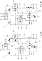
- FIG. 1 shows a hydraulic system 1 according to one embodiment of the present invention.
- the hydraulic system 1 includes: a single-rod hydraulic cylinder 4; a pump 2 connected to the hydraulic cylinder 4 in a manner to form a closed circuit; and a rotating machine 3 driving the pump 2.
- a hydraulic liquid flowing through the closed circuit is typically oil, but may be a liquid different from oil.
- the hydraulic cylinder 4 includes a rod-side chamber 41 and a head-side chamber 42, which are partitioned from each other by a piston.
- a rod extends from the piston and penetrates the rod-side chamber 41.
- the pump 2 includes a first port 21 and a second port 22.
- the first port 21 is connected to the rod-side chamber 41 of the hydraulic cylinder 4 by a rod-side supply line 51
- the second port 22 is connected to the head-side chamber 42 of the hydraulic cylinder 4 by a head-side supply line 52.
- the aforementioned closed circuit is formed between the pump 2 and the hydraulic cylinder 4.
- the pump 2 is a fixed displacement pump
- the rotating machine 3 is a servomotor.
- the delivery side and the suction side of the first and second ports 21 and 22 of the pump 2 are switched with each other in accordance with the rotation direction of the rotating machine 3.
- the speed and position of the hydraulic cylinder 4 are controlled by controlling the rotation speed and rotation angle of the servomotor.
- the pump 2 may be a variable displacement pump, such as a swash plate pump or a bent axis pump.
- the pump 2 may be an over-center pump configured such that, even though the rotation direction remains the same direction, the delivery side and the suction side of the first and second ports 21 and 22 are switchable with each other by tilting the swash plate or the tilted axis bi-directionally over a reference line (in a case where the pump 2 is a swash plate pump, the reference line is a line orthogonal to the center line of the pump2, whereas in a case where the pump 2 is a bent axis pump, the reference line is the center line of the pump 2).
- the rotating machine 3 may be an engine, or may be an inverter motor.
- a drain line 23 extends from the pump 2 to a tank 11. When the pump 2 is driven, a slight amount of hydraulic liquid flows from the pump 2 to the tank 11 through the drain line 23.
- a first tank line 6 is branched off from the rod-side supply line 51, and a second tank line 7 is branched off from the head-side supply line 52.
- the first tank line 6 and the second tank line 7 connect to the tank 11.
- the first tank line 6 is provided with a check valve 61.
- the check valve 61 allows a flow from the tank 11 toward the rod-side supply line 51, and prevents the reverse flow.
- the second tank line 7 is provided with a head-side counter balance valve 8A.
- the head-side counter balance valve 8A moves in accordance with an internal pilot pressure and an external pilot pressure.
- a pressure Prl of the rod-side supply line 51 (to be exact, the pressure of a portion of the rod-side supply line 51 between the pump 2 and a rod-side counter balance valve 8B described below) is led to the head-side counter balance valve 8A through an external pilot line 91.
- the head-side counter balance valve 8A allows a flow from the tank 11 toward the head-side supply line 52.
- the head-side counter balance valve 8A prevents a flow from the head-side supply line 52 toward the tank 11 when a head-side reference pressure Ps1 is lower than a setting pressure P1, and allows the flow from the head-side supply line 52 toward the tank 11 when the head-side reference pressure Ps1 is higher than the setting pressure P1.
- the head-side reference pressure Ps1 is based on the pressure Prl of the rod-side supply line 51, which is the external pilot pressure, and a pressure Ph1 of the head-side supply line 52, which is the internal pilot pressure.
- the setting pressure P1 of the head-side counter balance valve 8A is set to be higher than an expected maximum pressure of the head-side chamber 42 when the hydraulic cylinder 4 extends.
- the aforementioned coefficient C1 is, for example, 1.5 to 10.
- the head-side counter balance valve 8A has a structure in which a relief valve 81 and a check valve 82, which are parallel to each other, are incorporated in a housing.
- the relief valve 81 includes: a spool that slides within the housing; and a spring that urges the spool in the axial direction of the spool from one side.
- the spool receives the pressure Ph1 of the head-side supply line 52 (i.e., internal pilot pressure) and the pressure Prl of the rod-side supply line 51 (i.e., external pilot pressure), which are applied to the spool from the other side of the axial direction of the spool.
- the setting pressure P1 is the setting pressure of the relief valve 81.
- the aforementioned coefficient C1 indicates the ratio between an area over which the spool receives the internal pilot pressure and an area over which the spool receives the external pilot pressure.
- the rod-side supply line 51 is provided with the rod-side counter balance valve 8B.
- the rod-side counter balance valve 8B moves in accordance with an internal pilot pressure and an external pilot pressure.
- the pressure Phl of the head-side supply line 52 is led to the rod-side counter balance valve 8B through an external pilot line 92.
- the external pilot line 92 connects to a portion of the second tank line 7 between the head-side counter balance valve 8A and the head-side supply line 52.
- the external pilot line 92 may connect to the head-side supply line 52.
- the rod-side counter balance valve 8B allows a flow from the pump 2 toward the rod-side chamber 41.
- the rod-side counter balance valve 8B prevents a flow from the rod-side chamber 41 toward the pump 2 when a rod-side reference pressure Ps2 is lower than a setting pressure P2, and allows the flow from the rod-side chamber 41 toward the pump 2 when the sum value Ps2 is higher than the setting pressure P2.
- the rod-side reference pressure Ps2 is based on the pressure Ph1 of the head-side supply line 52, which is the external pilot pressure, and a pressure Prc of the rod-side chamber 41, which is the internal pilot pressure.
- the setting pressure P2 of the rod-side counter balance valve 8B may be set to be lower than, higher than, or equal to the aforementioned setting pressure P1 of the head-side counter balance valve 8A.
- the aforementioned coefficient C2 is, for example, 1.5 to 10.
- the pressure of the rod-side supply line 51 becomes high.
- the head-side counter balance valve 8A opens due to the external pilot pressure (the pressure Prl of the rod-side supply line 51), and the hydraulic liquid in an amount corresponding to the area difference between the rod-side chamber 41 and the head-side chamber 42 of the hydraulic cylinder 4 flows into the tank 11 through the second tank line 7.
- the head-side counter balance valve 8A opens even in a case where the pressure Prl of the rod-side supply line 51 is relatively low. This makes it possible to reduce the generation of heat that is caused by the passing of the hydraulic liquid through the head-side counter balance valve 8A.
- the head-side counter balance valve 8A opens regardless of the load direction. This makes it possible to control the speed of the hydraulic cylinder 4 by the delivery flow rate of the pump 2 (the flow rate at the rod side of the hydraulic cylinder 4). Accordingly, even if the load direction is reversed when the hydraulic cylinder 4 retracts, a change in the speed of the hydraulic cylinder 4 can be suppressed.
- the load direction when the hydraulic cylinder 120 extends is the retracting direction as shown in FIG. 5A
- the hydraulic liquid in an amount corresponding to the area difference between the head-side chamber 42 and the rod-side chamber 41 of the hydraulic cylinder 120 is led from the tank 160 through the pilot check valve 142 of the first tank line 141.
- the speed of the hydraulic cylinder 120 is controlled by the delivery flow rate of the pump 110 (the flow rate at the head side of the hydraulic cylinder 4).
- the setting pressure P1 of the head-side counter balance valve 8A provided on the second tank line 7, which is branched off from the head-side supply line 52, is set to be higher than the expected maximum pressure of the head-side chamber 42. Therefore, when the hydraulic cylinder 4 extends, the head-side counter balance valve 8A does not open.
- the rod-side counter balance valve 8B opens due to the external pilot pressure (the pressure Ph1 of the head-side supply line 52).
- the coefficient C2 which is used when converting the pressure Ph1 of the head-side supply line 52 into the converted pressure Pc2
- the rod-side counter balance valve 8B opens even in a case where the pressure Ph1 of the head-side supply line 52 is relatively low. This makes it possible to reduce the generation of heat that is caused by the passing of the hydraulic liquid through the rod-side counter balance valve 8B.
- the head-side counter balance valve 8A is kept in a closed state due to the pressure Ph1 of the head-side supply line 52 and the setting pressure P1. Therefore, the hydraulic liquid in an amount corresponding to the area difference between the head-side chamber 42 and the rod-side chamber 41 of the hydraulic cylinder 4 is led from the tank 11 through the check valve 61 of the first tank line 6.
- the setting pressure P2 of the rod-side counter balance valve 8B can be set to be relatively low, which makes it possible to reduce the generation of heat that is caused by the passing of the hydraulic liquid through the rod-side counter balance valve 8B.
- the head-side counter balance valve 8A is kept in a closed state due to the pressure Ph1 of the head-side supply line 52 and the setting pressure P1. Therefore, the hydraulic liquid in an amount corresponding to the area difference between the head-side chamber 42 and the rod-side chamber 41 of the hydraulic cylinder 4 is led from the tank 11 through the check valve 61 of the first tank line 6.
- the hydraulic liquid is led from the tank 11 through the first tank line 6 regardless of the load direction.
- This makes it possible to control the speed of the hydraulic cylinder 4 by the delivery flow rate of the pump 2 (the flow rate at the head side of the hydraulic cylinder 4). Accordingly, even if the load direction is reversed when the hydraulic cylinder 4 extends, a change in the speed of the hydraulic cylinder 4 can be suppressed.
- the rod-side supply line 51 need not be provided with the rod-side counter balance valve 8B.
Landscapes
- Engineering & Computer Science (AREA)
- Physics & Mathematics (AREA)
- Fluid Mechanics (AREA)
- Mechanical Engineering (AREA)
- General Engineering & Computer Science (AREA)
- Fluid-Pressure Circuits (AREA)
Abstract
Description
- The present invention relates to a hydraulic system in which a single-rod hydraulic cylinder and a pump are connected in a manner to form a closed circuit.
- Conventionally, there is a known hydraulic system in which a single-rod hydraulic cylinder and a pump are connected in a manner to form a closed circuit. For example,
Patent Literature 1 discloses ahydraulic system 100 as shown inFIGS. 4A and 4B . - In the
hydraulic system 100, a single-rodhydraulic cylinder 120 and apump 110 are connected by a rod-side supply line 131 and a head-side supply line 132 in a manner to form a closed circuit. Afirst tank line 141 is branched off from the rod-side supply line 131, and asecond tank line 151 is branched off from the head-side supply line 132. Thefirst tank line 141 and thesecond tank line 151 are provided with apilot check valve 142 and apilot check valve 152, respectively. - The
pilot check valve 142 provided on thefirst tank line 141 stops exerting its reverse flow preventing function when the pressure of the head-side supply line 132 has become high, and thepilot check valve 152 provided on thesecond tank line 151 stops exerting its reverse flow preventing function when the pressure of the rod-side supply line 131 has become high. -
Patent Literature 2 discloses a hydraulic system in which a single-rod hydraulic cylinder is disposed in such a manner that the cylinder extends downward. In the hydraulic system, a head-side supply line is provided with a counter balance valve. -
- PTL 1: Japanese Laid-Open Patent Application Publication No.
2004-257448 - PTL 2: Japanese Patent No.
3833291 - In the
hydraulic system 100 disclosed byPatent Literature 1, if the load direction when thehydraulic cylinder 120 retracts is the extending direction of thecylinder 120 as shown inFIG. 4A , since the cylinder is moved in its retracting direction against the load, the pressure of the rod-side supply line 131 becomes high. Also, thepilot check valve 152 of thesecond tank line 151 is opened, and a hydraulic liquid in an amount corresponding to the area difference between the head-side chamber and the rod-side chamber of thehydraulic cylinder 120 flows into atank 160 through thesecond tank line 151. At the time, the speed of thehydraulic cylinder 120 is controlled by the delivery flow rate of the pump 110 (i.e., the flow rate at the rod side of the hydraulic cylinder 120). - However, if the load direction is reversed into the retracting direction as shown in
FIG. 4B , the pressure of the head-side supply line 132 becomes high, and the pressure at the suction side of thepump 110 becomes high. Accordingly, thepump 110 is driven by this pressurized oil. Also, thepilot check valve 142 of thefirst tank line 141 is opened due to the pressure of the head-side supply line 132, and the hydraulic liquid in an amount corresponding to the area difference between the rod-side chamber and the head-side chamber of thehydraulic cylinder 120 flows into thetank 160 through thefirst tank line 141. At the time, the speed of thehydraulic cylinder 120 is controlled by the suction flow rate of the pump 110 (i.e., the flow rate at the head side of the hydraulic cylinder 4). That is, when thehydraulic cylinder 120 retracts, if the load direction is reversed from the extending direction to the retracting direction, or reversed from the retracting direction to the extending direction, not only a mechanical shock, but also a change in the speed of thehydraulic cylinder 120 occurs. - It should be noted that due to the orientation of the hydraulic cylinder in the hydraulic system disclosed by
Patent Literature 2,Patent Literature 2 does not assume that the load is applied in the retracting direction when the hydraulic cylinder retracts. - In view of the above, an object of the present invention is to provide a hydraulic system that is capable of suppressing a change in the speed of a hydraulic cylinder even if the load direction is reversed when the hydraulic cylinder retracts.
- In order to solve the above-described problems, a hydraulic system according to the present invention includes: a single-rod hydraulic cylinder including a rod-side chamber and a head-side chamber; a pump driven by a rotating machine, the pump including a first port and a second port; a rod-side supply line that connects the first port to the rod-side chamber; a head-side supply line that connects the second port to the head-side chamber in a manner to form a closed circuit together with the pump, the rod-side supply line, and the hydraulic cylinder; a first tank line that is branched off from the rod-side supply line and connects to a tank; a check valve provided on the first tank line, the check valve allowing a flow from the tank toward the rod-side supply line and preventing a reverse flow; a second tank line that is branched off from the head-side supply line and connects to the tank; and a head-side counter balance valve provided on the second tank line. A pressure of the rod-side supply line is led to the head-side counter balance valve through an external pilot line. The head-side counter balance valve is configured to: allow a flow from the tank toward the head-side supply line; and prevent a flow from the head-side supply line toward the tank when a head-side reference pressure is lower than a setting pressure, and allow the flow from the head-side supply line toward the tank when the head-side reference pressure is higher than the setting pressure, the head-side reference pressure being based on the pressure of the rod-side supply line and a pressure of the head-side supply line. The setting pressure is set to be higher than an expected maximum pressure of the head-side chamber when the hydraulic cylinder extends.
- According to the above configuration, the setting pressure of the head-side counter balance valve provided on the second tank line, which is branched off from the head-side supply line, is set to be higher than the expected maximum pressure of the head-side chamber. Therefore, when the hydraulic cylinder extends, the head-side counter balance valve does not open.
- In a case where the load direction when the hydraulic cylinder retracts is the extending direction of the cylinder, since the cylinder is moved in its retracting direction against the load, the pressure of the rod-side supply line becomes high, and the head-side counter balance valve opens. As a result, the hydraulic liquid in an amount corresponding to the area difference between the head-side chamber and the rod-side chamber of the hydraulic cylinder flows into the tank through the second tank line.
- On the other hand, in a case where the load direction when the hydraulic cylinder retracts is the retracting direction, the pressure of the rod-side supply line becomes high to some extent due to the function of the head-side counter balance valve, and the head-side counter balance valve opens. As a result, the hydraulic liquid in an amount corresponding to the area difference between the head-side chamber and the rod-side chamber of the hydraulic cylinder flows into the tank through the second tank line.
- As thus described, according to this configuration, when the hydraulic cylinder retracts, the head-side counter balance valve opens regardless of the load direction. This makes it possible to control the speed of the hydraulic cylinder by the flow rate into the rod-side chamber of the cylinder, i.e., the delivery flow rate of the pump. Accordingly, even if the load direction is reversed when the hydraulic cylinder retracts, a change in the speed of the hydraulic cylinder can be suppressed.
- The head-side reference pressure may be a sum value of a converted pressure and the pressure of the head-side supply line, the converted pressure being calculated by multiplying the pressure of the rod-side supply line by a coefficient. For example, if the coefficient used for calculating the converted pressure is set to be relatively great, the head-side counter balance valve opens even in a case where the pressure of the rod-side supply line is relatively low. This makes it possible to reduce the generation of heat that is caused by the passing of the hydraulic liquid through the head-side counter balance valve.
- The above hydraulic system may further include a rod-side counter balance valve provided on the rod-side supply line. The pressure of the head-side supply line may be led to the rod-side counter balance valve through an external pilot line. The rod-side counter balance valve may be configured to: allow a flow from the pump toward the rod-side chamber; and prevent a flow from the rod-side chamber toward the pump when a rod-side reference pressure is lower than a setting pressure, and allow the flow from the rod-side chamber toward the pump when the rod-side reference pressure is higher than the setting pressure, the rod-side reference pressure being based on the pressure of the head-side supply line and a pressure of the rod-side chamber.
- According to the above configuration, in a case where the load direction when the hydraulic cylinder extends is the retracting direction, since the pressure of the head-side supply line is high, the rod-side counter balance valve opens. Meanwhile, the head-side counter balance valve is kept in a closed state due to the pressure of the head-side supply line and the setting pressure. Therefore, the hydraulic liquid in an amount corresponding to the area difference between the head-side chamber and the rod-side chamber of the hydraulic cylinder is led from the tank through the check valve of the first tank line.
- On the other hand, in a case where the load direction when the hydraulic cylinder extends is the extending direction, the pressure of the rod-side chamber becomes high, and the rod-side counter balance valve opens. Unlike the head-side counter balance valve, the setting pressure of the rod-side counter balance valve can be set to be relatively low, which makes it possible to reduce the generation of heat that is caused by the passing of the hydraulic liquid through the rod-side counter balance valve. Although the pressure of the head-side supply line becomes high to some extent due to the function of the rod-side counter balance valve, the head-side counter balance valve is kept in a closed state due to the pressure of the head-side supply line and the setting pressure. Therefore, the hydraulic liquid in an amount corresponding to the area difference between the head-side chamber and the rod-side chamber of the hydraulic cylinder is led from the tank through the check valve of the first tank line.
- As thus described, according to this configuration, when the hydraulic cylinder extends, the hydraulic liquid is led from the tank through the first tank line regardless of the load direction. This makes it possible to control the speed of the hydraulic cylinder by the flow rate into the head-side chamber of the cylinder, i.e., the delivery flow rate of the pump. Accordingly, even if the load direction is reversed when the hydraulic cylinder extends, a change in the speed of the hydraulic cylinder can be suppressed.
- The rod-side reference pressure may be a sum value of a converted pressure and the pressure of the rod-side chamber, the converted pressure being calculated by multiplying the pressure of the head-side supply line by a coefficient. For example, if the coefficient used for calculating the converted pressure is set to be relatively great, the rod-side counter balance valve opens even in a case where the pressure of the head-side supply line is relatively low. This makes it possible to reduce the generation of heat that is caused by the passing of the hydraulic liquid through the rod-side counter balance valve.
- For example, the rotating machine may be a servomotor, and a delivery side and a suction side of the first and second ports of the pump may be switched with each other in accordance with a rotation direction of the rotating machine.
- The present invention makes it possible to suppress a change in the speed of a hydraulic cylinder even if the load direction is reversed when the hydraulic cylinder retracts.
-
-
FIG. 1 shows a schematic configuration of a hydraulic system according to one embodiment of the present invention. -
FIGS. 2A and 2B each show a flow of a hydraulic liquid when a hydraulic cylinder retracts;FIG. 2A shows the flow in a case where the load direction is the extending direction of the cylinder; andFIG. 2B shows the flow in a case where the load direction is the retracting direction of the cylinder. -
FIGS. 3A and 3B each show a flow of the hydraulic liquid when the hydraulic cylinder extends;FIG. 3A shows the flow in a case where the load direction is the retracting direction; andFIG. 3B shows the flow in a case where the load direction is the extending direction. -
FIGS. 4A and 4B each show a schematic configuration of a conventional hydraulic system, and each show a flow of a hydraulic liquid when a hydraulic cylinder retracts. -
FIGS. 5A and 5B each show a schematic configuration of the conventional hydraulic system, and each show a flow of the hydraulic liquid when the hydraulic cylinder extends. -
FIG. 1 shows ahydraulic system 1 according to one embodiment of the present invention. Thehydraulic system 1 includes: a single-rodhydraulic cylinder 4; apump 2 connected to thehydraulic cylinder 4 in a manner to form a closed circuit; and arotating machine 3 driving thepump 2. A hydraulic liquid flowing through the closed circuit is typically oil, but may be a liquid different from oil. - The
hydraulic cylinder 4 includes a rod-side chamber 41 and a head-side chamber 42, which are partitioned from each other by a piston. A rod extends from the piston and penetrates the rod-side chamber 41. - The
pump 2 includes afirst port 21 and asecond port 22. Thefirst port 21 is connected to the rod-side chamber 41 of thehydraulic cylinder 4 by a rod-side supply line 51, and thesecond port 22 is connected to the head-side chamber 42 of thehydraulic cylinder 4 by a head-side supply line 52. With these rod-side supply line 51 and head-side supply line 52, the aforementioned closed circuit is formed between thepump 2 and thehydraulic cylinder 4. - In the present embodiment, the
pump 2 is a fixed displacement pump, and therotating machine 3 is a servomotor. The delivery side and the suction side of the first andsecond ports pump 2 are switched with each other in accordance with the rotation direction of therotating machine 3. The speed and position of thehydraulic cylinder 4 are controlled by controlling the rotation speed and rotation angle of the servomotor. - It should be noted that the
pump 2 may be a variable displacement pump, such as a swash plate pump or a bent axis pump. Alternatively, thepump 2 may be an over-center pump configured such that, even though the rotation direction remains the same direction, the delivery side and the suction side of the first andsecond ports pump 2 is a swash plate pump, the reference line is a line orthogonal to the center line of the pump2, whereas in a case where thepump 2 is a bent axis pump, the reference line is the center line of the pump 2). In this case, the rotatingmachine 3 may be an engine, or may be an inverter motor. - In the present embodiment, a
drain line 23 extends from thepump 2 to atank 11. When thepump 2 is driven, a slight amount of hydraulic liquid flows from thepump 2 to thetank 11 through thedrain line 23. - A
first tank line 6 is branched off from the rod-side supply line 51, and asecond tank line 7 is branched off from the head-side supply line 52. Thefirst tank line 6 and thesecond tank line 7 connect to thetank 11. - The
first tank line 6 is provided with acheck valve 61. Thecheck valve 61 allows a flow from thetank 11 toward the rod-side supply line 51, and prevents the reverse flow. - The
second tank line 7 is provided with a head-sidecounter balance valve 8A. The head-sidecounter balance valve 8A moves in accordance with an internal pilot pressure and an external pilot pressure. A pressure Prl of the rod-side supply line 51 (to be exact, the pressure of a portion of the rod-side supply line 51 between thepump 2 and a rod-sidecounter balance valve 8B described below) is led to the head-sidecounter balance valve 8A through anexternal pilot line 91. - The head-side
counter balance valve 8A allows a flow from thetank 11 toward the head-side supply line 52. On the other hand, the head-sidecounter balance valve 8A prevents a flow from the head-side supply line 52 toward thetank 11 when a head-side reference pressure Ps1 is lower than a setting pressure P1, and allows the flow from the head-side supply line 52 toward thetank 11 when the head-side reference pressure Ps1 is higher than the setting pressure P1. The head-side reference pressure Ps1 is based on the pressure Prl of the rod-side supply line 51, which is the external pilot pressure, and a pressure Ph1 of the head-side supply line 52, which is the internal pilot pressure. Specifically, the head-side reference pressure Ps1 is the sum value of a converted pressure Pc1 and the pressure Ph1 of the head-side supply line 52 (Ps1 = Pc1 + Phi). The converted pressure Pc1 is calculated by multiplying the pressure Prl of the rod-side supply line 51 by a coefficient C1 (Pc1 = Prl × C1). - The setting pressure P1 of the head-side
counter balance valve 8A is set to be higher than an expected maximum pressure of the head-side chamber 42 when thehydraulic cylinder 4 extends. The aforementioned coefficient C1 is, for example, 1.5 to 10. - To be more specific, the head-side counter balance valve 8Ahas a structure in which a
relief valve 81 and acheck valve 82, which are parallel to each other, are incorporated in a housing. Therelief valve 81 includes: a spool that slides within the housing; and a spring that urges the spool in the axial direction of the spool from one side. The spool receives the pressure Ph1 of the head-side supply line 52 (i.e., internal pilot pressure) and the pressure Prl of the rod-side supply line 51 (i.e., external pilot pressure), which are applied to the spool from the other side of the axial direction of the spool. The setting pressure P1 is the setting pressure of therelief valve 81. The aforementioned coefficient C1 indicates the ratio between an area over which the spool receives the internal pilot pressure and an area over which the spool receives the external pilot pressure. - It should be noted that the head-side reference pressure Ps1 may be the sum value of the pressure Prl of the rod-
side supply line 51 and a converted pressure Pd1 (Ps1 = Prl + Pd1). The converted pressure Pd1 is calculated by multiplying the pressure Ph1 of the head-side supply line 52 by a coefficient D1 (Pd1 = Ph1 × D1). In this case, the coefficient D1 is a value less than 1. - In the present embodiment, the rod-
side supply line 51 is provided with the rod-sidecounter balance valve 8B. The rod-sidecounter balance valve 8B moves in accordance with an internal pilot pressure and an external pilot pressure. The pressure Phl of the head-side supply line 52 is led to the rod-sidecounter balance valve 8B through anexternal pilot line 92. In the illustrated example, theexternal pilot line 92 connects to a portion of thesecond tank line 7 between the head-sidecounter balance valve 8A and the head-side supply line 52. Of course, theexternal pilot line 92 may connect to the head-side supply line 52. - The rod-side
counter balance valve 8B allows a flow from thepump 2 toward the rod-side chamber 41. On the other hand, the rod-sidecounter balance valve 8B prevents a flow from the rod-side chamber 41 toward thepump 2 when a rod-side reference pressure Ps2 is lower than a setting pressure P2, and allows the flow from the rod-side chamber 41 toward thepump 2 when the sum value Ps2 is higher than the setting pressure P2. The rod-side reference pressure Ps2 is based on the pressure Ph1 of the head-side supply line 52, which is the external pilot pressure, and a pressure Prc of the rod-side chamber 41, which is the internal pilot pressure. Specifically, the rod-side reference pressure Ps2 is the sum value of a converted pressure Pc2 and the pressure Prc of the rod-side chamber 41 (Ps2 = Pc2 + Prc). The converted pressure Pc2 is calculated by multiplying the pressure Ph1 of the head-side supply line 52 by a coefficient C2 (Pc2 = Ph1 × C2). It should be noted that the specific internal structure of the rod-sidecounter balance valve 8B is the same as that of the head-sidecounter balance valve 8A. - The setting pressure P2 of the rod-side
counter balance valve 8B may be set to be lower than, higher than, or equal to the aforementioned setting pressure P1 of the head-sidecounter balance valve 8A. The aforementioned coefficient C2 is, for example, 1.5 to 10. - It should be noted that the rod-side reference pressure Ps2 may be the sum value of the pressure Ph1 of the head-
side supply line 52 and a converted pressure Pd2 (Ps2 = Ph1 + Pd2). The converted pressure Pd2 is calculated by multiplying the pressure Prc of the rod-side chamber 41 by a coefficient D2 (Pd2 = Prc × D2). In this case, the coefficient D2 is a value less than 1. - Next, operations of the
hydraulic system 1 are described for the following two cases separately: when thehydraulic cylinder 4 retracts; and when thehydraulic cylinder 4 extends. - As shown in
FIG. 2A , in a case where the load direction when thehydraulic cylinder 4 retracts is the extending direction of thecylinder 4, the pressure of the rod-side supply line 51 becomes high. The head-sidecounter balance valve 8A opens due to the external pilot pressure (the pressure Prl of the rod-side supply line 51), and the hydraulic liquid in an amount corresponding to the area difference between the rod-side chamber 41 and the head-side chamber 42 of thehydraulic cylinder 4 flows into thetank 11 through thesecond tank line 7. At the time, if the coefficient C1, which is used when converting the pressure Prl of the rod-side supply line 51 into the converted pressure Pc1, is set to be relatively great, the head-sidecounter balance valve 8A opens even in a case where the pressure Prl of the rod-side supply line 51 is relatively low. This makes it possible to reduce the generation of heat that is caused by the passing of the hydraulic liquid through the head-sidecounter balance valve 8A. - It should be noted that if the flow rate into the
tank 11 is Qo, then Qo = Qh - Qr - α. - On the other hand, as shown in
FIG. 2B , in a case where the load direction when thehydraulic cylinder 4 retracts is the retracting direction of thecylinder 4, the pressure of the rod-side supply line 51 becomes high to some extent due to the function of the head-sidecounter balance valve 8A, and the head-sidecounter balance valve 8A opens due to the internal pilot pressure (the pressure Ph1 of the head-side supply line 52) and the external pilot pressure (the pressure Prl of the rod-side supply line 51). As a result, the hydraulic liquid in an amount corresponding to the area difference between the head-side chamber 42 and the rod-side chamber 41 of thehydraulic cylinder 4 flows into thetank 11 through thesecond tank line 7. - As described above, in the present embodiment, when the
hydraulic cylinder 4 retracts, the head-sidecounter balance valve 8A opens regardless of the load direction. This makes it possible to control the speed of thehydraulic cylinder 4 by the delivery flow rate of the pump 2 (the flow rate at the rod side of the hydraulic cylinder 4). Accordingly, even if the load direction is reversed when thehydraulic cylinder 4 retracts, a change in the speed of thehydraulic cylinder 4 can be suppressed. - First, for the sake of comparison, operations of the conventional
hydraulic system 100 are described with reference toFIGS. 5A and 5B . - In the conventional
hydraulic system 100, in a case where the load direction when thehydraulic cylinder 120 extends is the retracting direction as shown inFIG. 5A , since the pressure of the head-side supply line 132 is high, the hydraulic liquid in an amount corresponding to the area difference between the head-side chamber 42 and the rod-side chamber 41 of thehydraulic cylinder 120 is led from thetank 160 through thepilot check valve 142 of thefirst tank line 141. At the time, the speed of thehydraulic cylinder 120 is controlled by the delivery flow rate of the pump 110 (the flow rate at the head side of the hydraulic cylinder 4). - However, as shown in
FIG. 5B , if the load direction is reversed into the extending direction, the pressure of the rod-side supply line 131 becomes high, and the hydraulic liquid in an amount corresponding to the area difference between the head-side chamber 42 and the rod-side chamber 41 of thehydraulic cylinder 120 is led from thetank 160 through thepilot check valve 152 of thesecond tank line 151. At the time, the speed of thehydraulic cylinder 120 is controlled by the suction flow rate of the pump 110 (the flow rate at the rod side of the hydraulic cylinder 4). That is, when thehydraulic cylinder 120 extends, if the load direction is reversed from the extending direction to the retracting direction, or reversed from the retracting direction to the extending direction, not only a mechanical shock, but also a change in the speed of thehydraulic cylinder 120 occurs. - In this respect, in the
hydraulic system 1 of the present embodiment, when thehydraulic cylinder 4 extends, even if the load direction is reversed, a change in the speed of thehydraulic cylinder 4 can be suppressed for the reasons described below. - It should be noted that the setting pressure P1 of the head-side
counter balance valve 8A provided on thesecond tank line 7, which is branched off from the head-side supply line 52, is set to be higher than the expected maximum pressure of the head-side chamber 42. Therefore, when thehydraulic cylinder 4 extends, the head-sidecounter balance valve 8A does not open. - As shown in
FIG. 3A , in a case where the load direction when thehydraulic cylinder 4 extends is the retracting direction, since the pressure of the head-side supply line 52 is high, the rod-sidecounter balance valve 8B opens due to the external pilot pressure (the pressure Ph1 of the head-side supply line 52). At the time, if the coefficient C2, which is used when converting the pressure Ph1 of the head-side supply line 52 into the converted pressure Pc2, is set to be relatively great, the rod-sidecounter balance valve 8B opens even in a case where the pressure Ph1 of the head-side supply line 52 is relatively low. This makes it possible to reduce the generation of heat that is caused by the passing of the hydraulic liquid through the rod-sidecounter balance valve 8B. Meanwhile, the head-sidecounter balance valve 8A is kept in a closed state due to the pressure Ph1 of the head-side supply line 52 and the setting pressure P1. Therefore, the hydraulic liquid in an amount corresponding to the area difference between the head-side chamber 42 and the rod-side chamber 41 of thehydraulic cylinder 4 is led from thetank 11 through thecheck valve 61 of thefirst tank line 6. - It should be noted that if the flow rate led from the
tank 11 is Qi, the flow rate into the head-side chamber 42 is Qh, the flow rate out of the rod-side chamber 41 is Qr, and the drain amount from thepump 2 is α, then Qi = Qh + α - Qr. - On the other hand, as shown in
FIG. 3B , in a case where the load direction when thehydraulic cylinder 4 extends is the extending direction, the pressure of the rod-side chamber 41 becomes high, and the rod-sidecounter balance valve 8B opens due to the internal pilot pressure (the pressure Prc of the rod-side chamber 41). Unlike the head-sidecounter balance valve 8A, the setting pressure P2 of the rod-sidecounter balance valve 8B can be set to be relatively low, which makes it possible to reduce the generation of heat that is caused by the passing of the hydraulic liquid through the rod-sidecounter balance valve 8B. Although the pressure of the head-side supply line 52 becomes high to some extent due to the function of the rod-sidecounter balance valve 8B, the head-sidecounter balance valve 8A is kept in a closed state due to the pressure Ph1 of the head-side supply line 52 and the setting pressure P1. Therefore, the hydraulic liquid in an amount corresponding to the area difference between the head-side chamber 42 and the rod-side chamber 41 of thehydraulic cylinder 4 is led from thetank 11 through thecheck valve 61 of thefirst tank line 6. - As described above, in the present embodiment, when the
hydraulic cylinder 4 extends, the hydraulic liquid is led from thetank 11 through thefirst tank line 6 regardless of the load direction. This makes it possible to control the speed of thehydraulic cylinder 4 by the delivery flow rate of the pump 2 (the flow rate at the head side of the hydraulic cylinder 4). Accordingly, even if the load direction is reversed when thehydraulic cylinder 4 extends, a change in the speed of thehydraulic cylinder 4 can be suppressed. - The present invention is not limited to the above-described embodiment. Various modifications can be made without departing from the scope of the present invention.
- For example, depending on the usage, the rod-
side supply line 51 need not be provided with the rod-sidecounter balance valve 8B. -
- 1
- hydraulic system
- 11
- tank
- 2
- pump
- 21
- first port
- 22
- second port
- 3
- rotating machine
- 4
- hydraulic cylinder
- 41
- rod-side chamber
- 42
- head-side chamber
- 51
- head-side supply line
- 52
- rod-side supply line
- 6
- first tank line
- 61
- check valve
- 7
- second tank line
- 8A
- head-side counter balance valve
- 8B
- rod-side counter balance valve
- 91, 92
- external pilot line
Claims (5)
- A hydraulic system comprising:a single-rod hydraulic cylinder including a rod-side chamber and a head-side chamber;a pump driven by a rotating machine, the pump including a first port and a second port;a rod-side supply line that connects the first port to the rod-side chamber;a head-side supply line that connects the second port to the head-side chamber in a manner to form a closed circuit together with the pump, the rod-side supply line, and the hydraulic cylinder;a first tank line that is branched off from the rod-side supply line and connects to a tank;a check valve provided on the first tank line, the check valve allowing a flow from the tank toward the rod-side supply line and preventing a reverse flow;a second tank line that is branched off from the head-side supply line and connects to the tank; anda head-side counter balance valve provided on the second tank line, whereina pressure of the rod-side supply line is led to the head-side counter balance valve through an external pilot line,the head-side counter balance valve is configured to:allow a flow from the tank toward the head-side supply line; andprevent a flow from the head-side supply line toward the tank when a head-side reference pressure is lower than a setting pressure, and allow the flow from the head-side supply line toward the tank when the head-side reference pressure is higher than the setting pressure, the head-side reference pressure being based on the pressure of the rod-side supply line and a pressure of the head-side supply line, andthe setting pressure is set to be higher than an expected maximum pressure of the head-side chamber when the hydraulic cylinder extends.
- The hydraulic system according to claim 1, wherein
the head-side reference pressure is a sum value of a converted pressure and the pressure of the head-side supply line, the converted pressure being calculated by multiplying the pressure of the rod-side supply line by a coefficient. - The hydraulic system according to claim 1 or 2, further comprising a rod-side counter balance valve provided on the rod-side supply line, wherein
the pressure of the head-side supply line is led to the rod-side counter balance valve through an external pilot line, and
the rod-side counter balance valve is configured to:allow a flow from the pump toward the rod-side chamber; andprevent a flow from the rod-side chamber toward the pump when a rod-side reference pressure is lower than a setting pressure, and allow the flow from the rod-side chamber toward the pump when the rod-side reference pressure is higher than the setting pressure, the rod-side reference pressure being based on the pressure of the head-side supply line and a pressure of the rod-side chamber. - The hydraulic system according to claim 3, wherein
the rod-side reference pressure is a sum value of a converted pressure and the pressure of the rod-side chamber, the converted pressure being calculated by multiplying the pressure of the head-side supply line by a coefficient. - The hydraulic system according to any one of claims 1 to 4, wherein
the rotating machine is a servomotor, and
a delivery side and a suction side of the first and second ports of the pump are switched with each other in accordance with a rotation direction of the rotating machine.
Applications Claiming Priority (2)
| Application Number | Priority Date | Filing Date | Title |
|---|---|---|---|
| JP2017190722A JP6467479B1 (en) | 2017-09-29 | 2017-09-29 | Hydraulic system |
| PCT/JP2018/035100 WO2019065509A1 (en) | 2017-09-29 | 2018-09-21 | Hydraulic system |
Publications (2)
| Publication Number | Publication Date |
|---|---|
| EP3690257A1 true EP3690257A1 (en) | 2020-08-05 |
| EP3690257A4 EP3690257A4 (en) | 2021-06-16 |
Family
ID=65356033
Family Applications (1)
| Application Number | Title | Priority Date | Filing Date |
|---|---|---|---|
| EP18862710.3A Withdrawn EP3690257A4 (en) | 2017-09-29 | 2018-09-21 | HYDRAULIC SYSTEM |
Country Status (3)
| Country | Link |
|---|---|
| EP (1) | EP3690257A4 (en) |
| JP (1) | JP6467479B1 (en) |
| WO (1) | WO2019065509A1 (en) |
Families Citing this family (1)
| Publication number | Priority date | Publication date | Assignee | Title |
|---|---|---|---|---|
| DE102021204291B3 (en) * | 2021-04-29 | 2022-06-15 | Hawe Hydraulik Se | Hydraulic system for a mobile rescue stretcher and mobile rescue stretcher |
Family Cites Families (9)
| Publication number | Priority date | Publication date | Assignee | Title |
|---|---|---|---|---|
| JPS5185186U (en) * | 1974-12-27 | 1976-07-08 | ||
| FR2671144B1 (en) * | 1990-12-28 | 1994-10-21 | Faivre Duboz Denis | DEVICE FOR CONTROLLING A SELF-CONTAINED CYLINDER. |
| JP3833291B2 (en) * | 1995-12-22 | 2006-10-11 | 豊興工業株式会社 | Hydraulic pressure processing machine |
| JPH10166199A (en) * | 1996-12-05 | 1998-06-23 | Daiichi Denki Kk | Hydraulic driven plastic working machine |
| JP4965762B2 (en) * | 2000-10-31 | 2012-07-04 | 第一電気株式会社 | Hydraulic multiple drive device, gate control device and winged body control device |
| JP2004257448A (en) | 2003-02-25 | 2004-09-16 | Shin Meiwa Ind Co Ltd | Hydraulic drive |
| JP4083093B2 (en) * | 2003-07-10 | 2008-04-30 | 株式会社不二越 | Double-rotating hydraulic pump circuit |
| JP2012002326A (en) * | 2010-06-21 | 2012-01-05 | Caterpillar Japan Ltd | Hydraulic drive device of dismantling working machine |
| CN107567410A (en) * | 2015-05-28 | 2018-01-09 | 韦伯水力有限公司 | Hydrostatic regulating loop and application thereof |
-
2017
- 2017-09-29 JP JP2017190722A patent/JP6467479B1/en active Active
-
2018
- 2018-09-21 EP EP18862710.3A patent/EP3690257A4/en not_active Withdrawn
- 2018-09-21 WO PCT/JP2018/035100 patent/WO2019065509A1/en not_active Ceased
Also Published As
| Publication number | Publication date |
|---|---|
| EP3690257A4 (en) | 2021-06-16 |
| WO2019065509A1 (en) | 2019-04-04 |
| JP2019065935A (en) | 2019-04-25 |
| JP6467479B1 (en) | 2019-02-13 |
Similar Documents
| Publication | Publication Date | Title |
|---|---|---|
| JP5972879B2 (en) | Hydraulic drive system | |
| CN105190052B (en) | The hydraulic system of engineering machinery | |
| CN105074096B (en) | The hydraulic system of engineering machinery | |
| US11015723B2 (en) | Directional valve comprising a damping system for controlling a torque motor of a construction machine | |
| KR20140007860A (en) | Oil pump with selectable outlet pressure | |
| RU2312256C2 (en) | Hydraulic control unit and method to control hydraulically-controlled device | |
| CN104214150A (en) | Double hoist hydraulic control system and construction machinery with it | |
| US9845589B2 (en) | Hydraulic drive system for construction machine | |
| KR20140093657A (en) | Oil-pressure control system | |
| CN103256265B (en) | Hydrostatic drive system | |
| CN105143669B (en) | Pump discharge flow rate control device | |
| EP3309408A1 (en) | Hydraulic systems for construction machinery | |
| US10907659B2 (en) | Hydraulic system | |
| US10851772B2 (en) | Hydraulic drive | |
| CN109058210A (en) | A kind of valve post-compensation system that pressure difference is constant | |
| EP3078570A1 (en) | Hydraulic steering system | |
| US10619753B2 (en) | Pilot type switching valve | |
| CN102734241A (en) | Opened and closed hydraulic system and engineering machinery | |
| CA3200619C (en) | Hydraulic system switchable between fixed-displacement and fixed/variable-displacement, control method thereof and working machine | |
| CN211202468U (en) | Closed plunger pump | |
| CN105545839A (en) | Oil cylinder reversing and volume speed adjusting hydraulic system | |
| JP6467479B1 (en) | Hydraulic system | |
| CN204828113U (en) | Valve module, including hydraulic system and machine of this valve module | |
| JP2024009598A (en) | hydraulic system | |
| CN207583724U (en) | A kind of board-like sterilization machine hydraulic equipment check valve |
Legal Events
| Date | Code | Title | Description |
|---|---|---|---|
| STAA | Information on the status of an ep patent application or granted ep patent |
Free format text: STATUS: THE INTERNATIONAL PUBLICATION HAS BEEN MADE |
|
| PUAI | Public reference made under article 153(3) epc to a published international application that has entered the european phase |
Free format text: ORIGINAL CODE: 0009012 |
|
| STAA | Information on the status of an ep patent application or granted ep patent |
Free format text: STATUS: REQUEST FOR EXAMINATION WAS MADE |
|
| 17P | Request for examination filed |
Effective date: 20200428 |
|
| AK | Designated contracting states |
Kind code of ref document: A1 Designated state(s): AL AT BE BG CH CY CZ DE DK EE ES FI FR GB GR HR HU IE IS IT LI LT LU LV MC MK MT NL NO PL PT RO RS SE SI SK SM TR |
|
| AX | Request for extension of the european patent |
Extension state: BA ME |
|
| DAV | Request for validation of the european patent (deleted) | ||
| DAX | Request for extension of the european patent (deleted) | ||
| A4 | Supplementary search report drawn up and despatched |
Effective date: 20210519 |
|
| RIC1 | Information provided on ipc code assigned before grant |
Ipc: F15B 11/00 20060101AFI20210513BHEP Ipc: F15B 11/08 20060101ALI20210513BHEP Ipc: F15B 7/00 20060101ALI20210513BHEP Ipc: F15B 11/044 20060101ALI20210513BHEP Ipc: F15B 11/05 20060101ALI20210513BHEP |
|
| GRAP | Despatch of communication of intention to grant a patent |
Free format text: ORIGINAL CODE: EPIDOSNIGR1 |
|
| STAA | Information on the status of an ep patent application or granted ep patent |
Free format text: STATUS: GRANT OF PATENT IS INTENDED |
|
| INTG | Intention to grant announced |
Effective date: 20240618 |
|
| STAA | Information on the status of an ep patent application or granted ep patent |
Free format text: STATUS: THE APPLICATION IS DEEMED TO BE WITHDRAWN |
|
| 18D | Application deemed to be withdrawn |
Effective date: 20241019 |