EP3690197B1 - Gas turbine engine bypass drainage system - Google Patents
Gas turbine engine bypass drainage system Download PDFInfo
- Publication number
- EP3690197B1 EP3690197B1 EP20155000.1A EP20155000A EP3690197B1 EP 3690197 B1 EP3690197 B1 EP 3690197B1 EP 20155000 A EP20155000 A EP 20155000A EP 3690197 B1 EP3690197 B1 EP 3690197B1
- Authority
- EP
- European Patent Office
- Prior art keywords
- housing
- core housing
- core
- channel
- redirection device
- Prior art date
- Legal status (The legal status is an assumption and is not a legal conclusion. Google has not performed a legal analysis and makes no representation as to the accuracy of the status listed.)
- Active
Links
Images



Classifications
-
- F—MECHANICAL ENGINEERING; LIGHTING; HEATING; WEAPONS; BLASTING
- F02—COMBUSTION ENGINES; HOT-GAS OR COMBUSTION-PRODUCT ENGINE PLANTS
- F02C—GAS-TURBINE PLANTS; AIR INTAKES FOR JET-PROPULSION PLANTS; CONTROLLING FUEL SUPPLY IN AIR-BREATHING JET-PROPULSION PLANTS
- F02C7/00—Features, components parts, details or accessories, not provided for in, or of interest apart form groups F02C1/00 - F02C6/00; Air intakes for jet-propulsion plants
-
- F—MECHANICAL ENGINEERING; LIGHTING; HEATING; WEAPONS; BLASTING
- F02—COMBUSTION ENGINES; HOT-GAS OR COMBUSTION-PRODUCT ENGINE PLANTS
- F02C—GAS-TURBINE PLANTS; AIR INTAKES FOR JET-PROPULSION PLANTS; CONTROLLING FUEL SUPPLY IN AIR-BREATHING JET-PROPULSION PLANTS
- F02C7/00—Features, components parts, details or accessories, not provided for in, or of interest apart form groups F02C1/00 - F02C6/00; Air intakes for jet-propulsion plants
- F02C7/30—Preventing corrosion or unwanted deposits in gas-swept spaces
-
- F—MECHANICAL ENGINEERING; LIGHTING; HEATING; WEAPONS; BLASTING
- F01—MACHINES OR ENGINES IN GENERAL; ENGINE PLANTS IN GENERAL; STEAM ENGINES
- F01D—NON-POSITIVE DISPLACEMENT MACHINES OR ENGINES, e.g. STEAM TURBINES
- F01D25/00—Component parts, details, or accessories, not provided for in, or of interest apart from, other groups
-
- F—MECHANICAL ENGINEERING; LIGHTING; HEATING; WEAPONS; BLASTING
- F01—MACHINES OR ENGINES IN GENERAL; ENGINE PLANTS IN GENERAL; STEAM ENGINES
- F01D—NON-POSITIVE DISPLACEMENT MACHINES OR ENGINES, e.g. STEAM TURBINES
- F01D25/00—Component parts, details, or accessories, not provided for in, or of interest apart from, other groups
- F01D25/24—Casings; Casing parts, e.g. diaphragms, casing fastenings
-
- F—MECHANICAL ENGINEERING; LIGHTING; HEATING; WEAPONS; BLASTING
- F01—MACHINES OR ENGINES IN GENERAL; ENGINE PLANTS IN GENERAL; STEAM ENGINES
- F01D—NON-POSITIVE DISPLACEMENT MACHINES OR ENGINES, e.g. STEAM TURBINES
- F01D25/00—Component parts, details, or accessories, not provided for in, or of interest apart from, other groups
- F01D25/32—Collecting of condensation water; Drainage ; Removing solid particles
-
- F—MECHANICAL ENGINEERING; LIGHTING; HEATING; WEAPONS; BLASTING
- F02—COMBUSTION ENGINES; HOT-GAS OR COMBUSTION-PRODUCT ENGINE PLANTS
- F02K—JET-PROPULSION PLANTS
- F02K3/00—Plants including a gas turbine driving a compressor or a ducted fan
-
- F—MECHANICAL ENGINEERING; LIGHTING; HEATING; WEAPONS; BLASTING
- F05—INDEXING SCHEMES RELATING TO ENGINES OR PUMPS IN VARIOUS SUBCLASSES OF CLASSES F01-F04
- F05D—INDEXING SCHEME FOR ASPECTS RELATING TO NON-POSITIVE-DISPLACEMENT MACHINES OR ENGINES, GAS-TURBINES OR JET-PROPULSION PLANTS
- F05D2260/00—Function
- F05D2260/60—Fluid transfer
- F05D2260/602—Drainage
-
- F—MECHANICAL ENGINEERING; LIGHTING; HEATING; WEAPONS; BLASTING
- F05—INDEXING SCHEMES RELATING TO ENGINES OR PUMPS IN VARIOUS SUBCLASSES OF CLASSES F01-F04
- F05D—INDEXING SCHEME FOR ASPECTS RELATING TO NON-POSITIVE-DISPLACEMENT MACHINES OR ENGINES, GAS-TURBINES OR JET-PROPULSION PLANTS
- F05D2260/00—Function
- F05D2260/60—Fluid transfer
- F05D2260/605—Venting into the ambient atmosphere or the like
-
- F—MECHANICAL ENGINEERING; LIGHTING; HEATING; WEAPONS; BLASTING
- F05—INDEXING SCHEMES RELATING TO ENGINES OR PUMPS IN VARIOUS SUBCLASSES OF CLASSES F01-F04
- F05D—INDEXING SCHEME FOR ASPECTS RELATING TO NON-POSITIVE-DISPLACEMENT MACHINES OR ENGINES, GAS-TURBINES OR JET-PROPULSION PLANTS
- F05D2260/00—Function
- F05D2260/60—Fluid transfer
- F05D2260/608—Aeration, ventilation, dehumidification or moisture removal of closed spaces
-
- Y—GENERAL TAGGING OF NEW TECHNOLOGICAL DEVELOPMENTS; GENERAL TAGGING OF CROSS-SECTIONAL TECHNOLOGIES SPANNING OVER SEVERAL SECTIONS OF THE IPC; TECHNICAL SUBJECTS COVERED BY FORMER USPC CROSS-REFERENCE ART COLLECTIONS [XRACs] AND DIGESTS
- Y02—TECHNOLOGIES OR APPLICATIONS FOR MITIGATION OR ADAPTATION AGAINST CLIMATE CHANGE
- Y02T—CLIMATE CHANGE MITIGATION TECHNOLOGIES RELATED TO TRANSPORTATION
- Y02T50/00—Aeronautics or air transport
- Y02T50/60—Efficient propulsion technologies, e.g. for aircraft
Definitions
- Illustrative embodiments pertain to the art of turbomachinery, and specifically to drainage systems for gas turbine engines.
- Gas turbine engines are rotary-type combustion turbine engines built around a power core made up of a compressor, combustor and turbine, arranged in flow series with an upstream inlet and downstream exhaust.
- the compressor compresses air from the inlet, which is mixed with fuel in the combustor and ignited to generate hot combustion gas.
- the turbine extracts energy from the expanding combustion gas, and drives the compressor via a common shaft. Energy is delivered in the form of rotational energy in the shaft, reactive thrust from the exhaust, or both.
- the elements of the gas turbine engine i.e., core components, may be housed within a nacelle.
- fluids such as flammable fluids
- the drained fluids will subsequently flow along an exterior surface of the nacelle can come in to nacelle ventilation holes (e.g., scoops) and/or other holes or apertures (e.g., inlets or outlets) arranged to fluidly connected an exterior environment with the core components (e.g., fan duct apertures).
- the fluid may reenter the nacelle at these holes/apertures and interact with the core components.
- Such interaction may be detrimental to operation of the engine and/or may be a safety hazard (e.g., depending on the type of fluid that reenters the engine (e.g., fire, corrosion, ice, etc.)).
- Drain holes may be arranged on a low point of the nacelle, e.g., on an inner fixed structure of an engine, and may be arranged along a bypass duct of the engine. That is, the fluid will flow to a low point within the nacelle and then may leak through the joints, seams, or holes, to subsequently enter the bypass duct on the exterior of the nacelle structure.
- drain holes may be arranged upstream of core compartment ventilation/scoop holes.
- core compartment drain fluid e.g., oil, water, etc.
- US 5 054 282 discloses a drain assembly for a case with a minimized radial profile and to be assembly to an opening of the case while blocking the passage of flames from the exterior to the interior.
- US 5 104 069 , US 2010/293964 and US 2018/283217 also relate to drainage systems for aircraft.
- a core housing for a gas turbine includes a housing surface defining an exterior surface of the core housing, characterized in that the core housing further comprises a housing aperture arranged on the housing surface, the housing aperture configured to enable fluid communication between an external environment and an interior of the core housing, a drainage hole arranged upstream relative to the housing aperture, the drainage hole configured to enable draining of a fluid from an interior of the core housing to the external environment, and a redirection device arranged to receive a fluid from the drainage hole and direct such fluid away from the housing aperture.
- the core housing may include that the redirection device is mounted to the housing surface.
- the core housing may include that the redirection device is integrally formed with the core housing.
- the core housing may include that the redirection device has a channel body defining a channel extending between a channel inlet and a channel outlet.
- the core housing may include that the channel inlet is arranged proximate the drainage hole and at least partially covering the drainage hole.
- the core housing may include that the channel inlet is a closed channel inlet.
- the core housing may include that the channel body tapers from the channel inlet to the channel outlet.
- the core housing may include that the channel inlet has an inlet height defined from the housing surface and the channel outlet has an outlet height defined from the housing surface, wherein the inlet height is less than the outlet height.
- the core housing may include that the channel body comprises a first section and a second section, wherein the first section includes the channel inlet and the second section includes the channel outlet.
- the core housing may include that the first section extends in a first axial direction and the second section extends in a second axial direction, wherein the first axial direction is different from the second axial direction.
- the core housing may include that the first section and the second section form a continuous, curved channel body.
- the core housing may include that a cross-sectional area of the channel is equal to or greater than 0.6 times a cross-sectional area of the drainage hole.
- the core housing may include that the redirection device is formed from the same material as the core housing.
- the core housing may include that the redirection device is formed from a material different than the core housing.
- the core housing may include that the redirection device is attached to the housing surface by at least one of an adhesive, bonding, welding, and a mechanical fastener.
- the core housing may include that the redirection device is mounted to the housing surface at at least one of a gravitational low point and a geometric low point of the core housing.
- the core housing may include one or more core components installed within the core housing.
- the core housing may include that the one or more core components comprise a gas turbine engine.
- a gas turbine engine includes a core housing.
- the core housing has a housing surface defining an exterior surface of the core housing, a housing aperture arranged on the housing surface, the housing aperture configured to enable fluid communication between an external environment and an interior of the core housing, a drainage hole arranged upstream relative to the housing aperture, the drainage hole configured to enable draining of a fluid from an interior of the core housing to the external environment, and a redirection device arranged to receive a fluid from the drainage hole and direct such fluid away from the housing aperture.
- One or more core components are mounted within the core housing with a nacelle arranged about the core housing.
- a bifurcation structure is positioned to extend between and connecting the core housing to the nacelle, wherein the core housing is mounted within the nacelle by at least the bifurcation structure.
- the redirection device is positioned proximate a juncture between the bifurcation structure and the core housing.
- the gas turbine engine may include that the external environment is a bypass flow path define between the housing surface and an interior surface of the nacelle.
- FIG. 1 schematically illustrates a gas turbine engine 20.
- the gas turbine engine 20 is disclosed herein as a two-spool turbofan that generally incorporates a fan section 22, a compressor section 24, a combustor section 26 and a turbine section 28.
- the fan section 22 drives air along a bypass flow path B in a bypass duct, while the compressor section 24 drives air along a core flow path C for compression and communication into the combustor section 26 then expansion through the turbine section 28.
- FIG. 1 schematically illustrates a gas turbine engine 20.
- the gas turbine engine 20 is disclosed herein as a two-spool turbofan that generally incorporates a fan section 22, a compressor section 24, a combustor section 26 and a turbine section 28.
- the fan section 22 drives air along a bypass flow path B in a bypass duct
- the compressor section 24 drives air along a core flow path C for compression and communication into the combustor section 26 then expansion through the turbine section 28.
- the exemplary engine 20 generally includes a low speed spool 30 and a high speed spool 32 mounted for rotation about an engine central longitudinal axis A relative to an engine static structure 36 via several bearing systems 38. It should be understood that various bearing systems 38 at various locations may alternatively or additionally be provided, and the location of bearing systems 38 may be varied as appropriate to the application.
- the low speed spool 30 generally includes an inner shaft 40 that interconnects a fan 42, a low pressure compressor 44 and a low pressure turbine 46.
- the inner shaft 40 is connected to the fan 42 through a speed change mechanism, which in exemplary gas turbine engine 20 is illustrated as a geared architecture 48 to drive the fan 42 at a lower speed than the low speed spool 30.
- the high speed spool 32 includes an outer shaft 50 that interconnects a high pressure compressor 52 and high pressure turbine 54.
- a combustor 56 is arranged in exemplary gas turbine 20 between the high pressure compressor 52 and the high pressure turbine 54.
- An engine static structure 36 is arranged generally between the high pressure turbine 54 and the low pressure turbine 46.
- the engine static structure 36 further supports bearing systems 38 in the turbine section 28.
- the inner shaft 40 and the outer shaft 50 are concentric and rotate via bearing systems 38 about the engine central longitudinal axis A which is collinear with their longitudinal axes.
- each of the positions of the fan section 22, compressor section 24, combustor section 26, turbine section 28, and fan drive gear system 48 may be varied.
- gear system 48 may be located aft of combustor section 26 or even aft of turbine section 28, and fan section 22 may be positioned forward or aft of the location of gear system 48.
- the engine 20 in one non-limiting example is a high-bypass geared aircraft engine.
- the engine 20 bypass ratio is greater than about six (6), with an example embodiment being greater than about ten (10)
- the geared architecture 48 is an epicyclic gear train, such as a planetary gear system or other gear system, with a gear reduction ratio of greater than about 2.3
- the low pressure turbine 46 has a pressure ratio that is greater than about five.
- the engine 20 bypass ratio is greater than about ten (10:1)
- the fan diameter is significantly larger than that of the low pressure compressor 44
- the low pressure turbine 46 has a pressure ratio that is greater than about five 5:1.
- Low pressure turbine 46 pressure ratio is pressure measured prior to inlet of low pressure turbine 46 as related to the pressure at the outlet of the low pressure turbine 46 prior to an exhaust nozzle.
- the geared architecture 48 may be an epicycle gear train, such as a planetary gear system or other gear system, with a gear reduction ratio of greater than about 2.3:1. It should be understood, however, that the above parameters are only exemplary of one embodiment of a geared architecture engine and that the present disclosure is applicable to other gas turbine engines including direct drive turbofans.
- the fan section 22 of the engine 20 is designed for a particular flight condition--typically cruise at about 0.8Mach and about 35,000 feet (10,668 meters).
- 'TSFC' Thrust Specific Fuel Consumption
- Low fan pressure ratio is the pressure ratio across the fan blade alone, without a Fan Exit Guide Vane (“FEGV”) system.
- the low fan pressure ratio as disclosed herein according to one non-limiting embodiment is less than about 1.45.
- the "Low corrected fan tip speed” as disclosed herein according to one non-limiting embodiment is less than about 1150 ft/second (350.5 m/sec).
- gas turbine engine 20 is depicted as a turbofan, it should be understood that the concepts described herein are not limited to use with the described configuration, as the teachings may be applied to other types of engines such as, but not limited to, turbojets, turboshafts, and three-spool (plus fan) turbofans wherein an intermediate spool includes an intermediate pressure compressor (“IPC") between a low pressure compressor (“LPC”) and a high pressure compressor (“HPC”), and an intermediate pressure turbine (“IPT”) between the high pressure turbine (“HPT”) and the low pressure turbine (“LPT”).
- IPC intermediate pressure compressor
- LPC low pressure compressor
- HPC high pressure compressor
- IPT intermediate pressure turbine
- the gas turbine engine 200 may be similar to that shown and described with respect to FIG. 1 .
- the gas turbine engine 200 includes a nacelle 202 with a fan 204 located therein.
- the fan 204 is operably connected to core components 206 of the gas turbine engine 200.
- the core components 206 include a low pressure compressor section 208, a high pressure compressor section 210, a combustor section 212, a high pressure turbine 214, and a low pressure turbine 216.
- the core components 206 are housed within a core housing 218 which defines a flow path through the core components 206 for operation of the gas turbine engine 200. Exhaust from the core components 206 exits the core housing 218 through a core nozzle 220.
- the core components 206 within the core housing 218 are mounted within the nacelle 202. As shown, the core housing 218 is attached to the nacelle 202 by a lower bifurcation structure 222 and an upper bifurcation structure 224.
- a bypass flow path 226 is defined between the exterior of the core housing 218 and the nacelle 202 to enable bypass air to flow therethrough. The bypass air exits the bypass flow path 226 through a bypass duct nozzle 228.
- the lower and upper bifurcation structures 222, 224 are configured to fixedly mount the core components 206 within the nacelle 202 and are configured to aerodynamically divide the bypass flow through the bypass flow path 226.
- fluids may leak from the core components 206 and flow along an exterior surface of the core housing 218 (i.e., within the bypass flow path 226).
- the leaking fluid will flow aftward toward the bypass duct nozzle 228 along the exterior surface of the core housing 218.
- the flow of fluid exiting the core housing 218 may be controlled by drainage holes 230 formed in the core housing 218.
- the placement of the drainage holes 230 may be selected to prevent the fluid from interacting with one or more housing apertures 232 that are located downstream from the drainage holes 230.
- the housing apertures 232 may be inlets or outlets for fluid flow associated with the core components 206.
- one or more housing apertures 232 may be configured as scoops for capturing and directly air from the bypass flow path 226 into the core housing 218 to interact with one or more of the core components 206 (e.g., for cooling). In other configurations, one or more housing apertures 232 may be configured as outlets for ejecting hot air from one or more of the core components 206. Those of skill in the art will appreciate that the housing apertures 232 may be inlets or outlets arranged for other purposes, without departing from the scope of the present disclosure. The housing apertures 232 provide for fluid communication between the bypass flow path 226 (or other external environment) and one or more of the core components 206 (or the interior of the core housing 218).
- the location of the housing apertures 232 and the drainage holes 230 may be dictated by requirements for flow through the housing apertures 232 and arranging the drainage holes 230 at a low point on the core housing 218 to enable efficient bleeding of any fluids from the interior of the core housing 218 to the exterior thereof. Further, the location of the housing apertures 232 and/or the drainage holes 230 may be dependent upon the location and structure of the lower bifurcation structure 222 which will impact the airflow of the bypass air within the bypass flow path 226.
- redirection devices are provided to redirect an outward flow of a liquid through the drainage holes 230.
- the redirection devices may be configured to collect, direct, and/or expel fluid in a direction away from the housing apertures 232.
- the redirection devices of the present disclosure are configured to prevent ingestion or reinjection of the fluid into the core housing 218 and the prevent interaction of such fluid with one or more of the core components 206.
- FIG. 3 a schematic illustration of a gas turbine engine 300 is shown.
- the view shown in FIG. 3 is a partial isometric illustration of the bypass flow path 326 of the gas turbine engine 300.
- the gas turbine engine 300 may be substantially similar to that shown and described above.
- the gas turbine engine 300 includes a nacelle 302 and a core housing 318 that are fixedly connected by a lower bifurcation structure 322.
- the core housing 318 has a low point 334 where fluids of core components within the core housing 318 may collect (e.g., gravitational or geometric low point of the core housing 318).
- a drainage hole 330 is arranged to extract and remove the fluid from the core housing 318.
- the drainage hole 330 is located proximate the low point 334 of the core housing 318.
- the core housing 318 further includes a housing aperture 332, which may be configured as an outlet or vent or may be configured as an inlet or scoop (e.g., depending on the specific engine configuration).
- the drainage hole 330 is located upstream of the housing aperture 332.
- fluid that may drain from and through the drainage hole 330 may flow aftward toward the housing aperture 332.
- a redirection device of the present disclosure the fluid could be reintroduced into the interior of the core housing 318, which is undesirable.
- a redirection device may be formed about the drainage hole 330 to redirect such drained fluid such that it does not reenter the core housing 318 through the housing aperture 332.
- FIG. 3 is merely illustrative, and is not to be limiting.
- the number of drainage holes 330 and/or the number of housing apertures 332, and the locations thereof may be varied and may be dependent, in part, upon a given engine configuration.
- FIGS. 4A-4C schematic illustrations of a gas turbine engine 400 having a redirection device 436 in accordance with an embodiment of the present disclosure are shown.
- FIG. 4A is a partial isometric illustration of a core housing 418 with a lower bifurcation structure 422 extending therefrom (and connecting the core housing 418 to a nacelle, as shown and described above).
- FIGS. 4B-4C are enlarged illustrations of the redirection device 436 as mounted to an exterior of the core housing 418.
- the core housing 418 includes a drainage hole 430 and a housing aperture 432.
- the housing aperture 432 is located downstream from the drainage hole 430 and may provide for an inlet or an outlet of air to core components within the core housing 418, as described above.
- the redirection device 436 is mounted, affixed, or otherwise attached to the core housing 418 (or may be integrally formed therewith) and positioned about the drainage hole 430.
- the redirection device 436 may be a sheet metal component that is soldered, welded, or otherwise affixed to an exterior surface of the core housing 418.
- adhesives or other bonding mechanisms may be employed.
- the redirection device 436 may be formed of machined material of the core housing 418, or may be stamped or otherwise formed. Further still, the core housing 418 may be additively manufactured to have the redirection device 436 formed therewith. In some embodiments, the redirection device may be formed from the same material as the core housing, and in other embodiments, the material of the redirection device may be different from that material of the core housing.
- the redirection device 436 has a channel body 438 that extends between a channel inlet 440 and a channel outlet 442.
- the channel body 438 also has mounting elements 444 extending therefrom to enable mounting to a housing surface 446 of the core housing 418.
- the channel body 438 defines a channel 448 or fluid path for directing flow therethrough.
- the channel inlet 440 is arranged proximate the drainage hole 430 such that fluid flowing through the drainage hole 430 will enter the channel 448 (shown in FIG. 4B ) and flow along and/or through the channel 448 and exit the channel outlet 442.
- the redirection device 436 is arranged to ensure redirection of any fluid away from the housing aperture 432.
- FIGS. 5A-5B schematic illustrations of a redirection device 536 are shown.
- the redirection device 536 is mountable and/or part of a core housing 518, as shown and described above. Specifically, in this non-limiting illustrative embodiment, the redirection device 536 is mounted to and affixed to a housing surface 546 of the core housing 518.
- FIG. 5A illustrates an isometric view of the redirection device 536
- FIG. 5B illustrates a cross-sectional illustration of the redirection device 536 as viewed along the line B-B shown in FIG. 5A .
- the redirection device 536 has a channel body 538 extending between a channel inlet 540 and a channel outlet 542.
- the redirection device 536 is positioned such that the channel inlet 540 is located proximate to, and at least partially covering, a drainage hole 530 formed in the core housing 518.
- the position and arrangement of the redirection device 536 is such that the redirection device 536 can receive, channel, and direct fluids from the drainage hole 530 away from a housing aperture 532.
- the housing aperture 532 may be an inlet or outlet for air or other fluids and may be configured for enabling a cooling process associated with one or more core components housed within the core housing 518.
- the redirection device 536 defines a channel 548 through which fluid may be directed. Fluid may enter the channel 548 from the drainage hole 530 at a channel inlet 540 and flow along the channel body 538 toward a channel outlet 542. The fluid may then exit the channel outlet 542 and flow along the housing surface 546, but will not interact with (e.g., enter) the housing aperture 532.
- the channel outlet 542 is shown approximately even with the housing aperture 532, however, such arrangement is not to be limiting. In some embodiments, the location of the channel outlet 542 (and thus the length of the channel body 538) may be located downstream of the housing aperture 532.
- the channel outlet 542 may be arranged upstream of the housing aperture 532, but the arrangement and configuration of the redirection device 536 is such that fluid flowing from the drainage hole 530 is directed away from the housing aperture 532, thus preventing any such fluids from entering into the core housing 518 through the housing aperture 532.
- the redirection device 636 may be similar in structure and function to that shown and described above.
- the redirection device 636 includes a first section 638a and a second section 638b forming a channel body of the redirection device 636.
- the first section 638a is arranged proximate and at least partially covering a drainage hole 630 formed in a core housing 618.
- the first section 638a of the channel body defines, in part, a channel inlet 640. Fluid entering the redirection device 636 from the drainage hole 630 will enter the first section 638a and flow toward the second section 638b.
- the second section 638b is arranged to redirect a fluid flow such that fluid exiting the redirection device 636 will be directed away from a housing aperture 632, as described above. The fluid will then exit the redirection device 636 through a channel outlet 642, which is defined by the second section 638b of the channel body.
- the redirection device 636 is formed from two distinct sections 638a, 638b that form the channel body. As shown, the first section 638a extends in a first axial direction 650a and the second section 638b extends in a second axial direction 650b.
- the selection of the first and second axial directions 650a, 650b may be based, in part, on aerodynamics, fluid flow, and/or other considerations. For example, the first axial direction 650a may be selected to minimize entrance drag at the channel inlet 640, and the second axial direction 650b may be selected to ensure no fluid exiting the redirection device 636 will interact with (e.g., enter) the housing aperture 632.
- the first axial direction 650a may be different than the second axial direction 650b.
- the channel body may be formed as a single unitary piece that is curved and transitions from a first axial direction at the channel inlet to a second axial direction at the channel outlet.
- the present illustration is not to be limiting, but rather is provided for illustrative and explanatory purposes.
- the redirection device 736 may be similar in structure and function to that shown and described above.
- the redirection device 736 includes a tapered channel body 738.
- the taper channel body 738 extends between a channel inlet 740 and a channel outlet 742.
- the redirection device 736 is mounted to a housing surface 746 of a core housing 718.
- the channel inlet 740 is arranged proximate to and at least partially covering a drainage hole 730, as described above.
- the channel inlet 740 of the channel body 738 has an inlet height HI as defined from the housing surface 746 of the core housing 718.
- the channel outlet 742 of the channel body 738 has an outlet height HO as defined from the housing surface 746 of the core housing 718.
- the outlet height HO is greater than the inlet height HI, thus creating a tapered channel body 738.
- the taper of the channel body 738 may aid in the flow and directing of a fluid received from the drainage hole 730.
- FIGS. 8A-8B an alternative configuration of a redirection device 836 in accordance with an embodiment of the present disclosure is shown.
- the redirection device 836 may be similar in structure and function to that shown and described above.
- the redirection device 836 includes a closed channel inlet 852.
- the closed channel inlet 852 may be configured to minimize drag at the closed channel inlet 852.
- a channel outlet 842 may remain open, and a suction force generated by airflow at the channel outlet 842 may, in part, cause a fluid from a drainage hole 830 to flow through the redirection device 836 and be directed away from a housing aperture, as described above.
- a curved or two-axis, tapered redirection device with a closed channel inlet may be implemented.
- other variations may be implemented without departing from the scope of the present disclosure.
- a taper in the opposing direction to that shown in FIG. 7 may be employed.
- a substantially closed channel outlet may be employed, with a hole formed in a surface of the redirection device, the hole arranged to provide an outlet for fluid within the redirection device.
- the cross-sectional area of the channel may be configured with a specific cross-sectional area related to the area of the drainage hole (e.g., drainage hole 530 shown in FIG. 5B ).
- embodiments described herein provide for improved drainage of fluids from core components of a gas turbine engine.
- embodiments described here can allow for optimum or desired core compartment ventilation holes and scoops (i.e., housing apertures) while mitigating risks associated with re-injection of fluids that drain from the core components.
- the term "about” is intended to include the degree of error associated with measurement of the particular quantity based upon the equipment available at the time of filing the application. For example, “about” may include a range of ⁇ 8%, or 5%, or 2% of a given value or other percentage change as will be appreciated by those of skill in the art for the particular measurement and/or dimensions referred to herein.
Landscapes
- Engineering & Computer Science (AREA)
- Mechanical Engineering (AREA)
- General Engineering & Computer Science (AREA)
- Chemical & Material Sciences (AREA)
- Combustion & Propulsion (AREA)
- Structures Of Non-Positive Displacement Pumps (AREA)
- Turbine Rotor Nozzle Sealing (AREA)
Description
- Illustrative embodiments pertain to the art of turbomachinery, and specifically to drainage systems for gas turbine engines.
- Gas turbine engines are rotary-type combustion turbine engines built around a power core made up of a compressor, combustor and turbine, arranged in flow series with an upstream inlet and downstream exhaust. The compressor compresses air from the inlet, which is mixed with fuel in the combustor and ignited to generate hot combustion gas. The turbine extracts energy from the expanding combustion gas, and drives the compressor via a common shaft. Energy is delivered in the form of rotational energy in the shaft, reactive thrust from the exhaust, or both.
- The elements of the gas turbine engine, i.e., core components, may be housed within a nacelle. In operation, fluids, such as flammable fluids, may drain from the core compartments through joints, seams, holes, etc. The drained fluids will subsequently flow along an exterior surface of the nacelle can come in to nacelle ventilation holes (e.g., scoops) and/or other holes or apertures (e.g., inlets or outlets) arranged to fluidly connected an exterior environment with the core components (e.g., fan duct apertures). The fluid may reenter the nacelle at these holes/apertures and interact with the core components. Such interaction may be detrimental to operation of the engine and/or may be a safety hazard (e.g., depending on the type of fluid that reenters the engine (e.g., fire, corrosion, ice, etc.)).
- Drain holes may be arranged on a low point of the nacelle, e.g., on an inner fixed structure of an engine, and may be arranged along a bypass duct of the engine. That is, the fluid will flow to a low point within the nacelle and then may leak through the joints, seams, or holes, to subsequently enter the bypass duct on the exterior of the nacelle structure. In some engine/nacelle configurations/designed, drain holes may be arranged upstream of core compartment ventilation/scoop holes. Typically, there is a low bifurcation at the low part of the bypass duct, which deviates or splits the air flow stream through the bypass duct. Such air flow streamlines deviation and can direct core compartment drain fluid (e.g., oil, water, etc.) into downstream holes that can create safety hazard risk situations by enables the drain fluid to renter the engine and interact with the core components.
-
US 5 054 282 discloses a drain assembly for a case with a minimized radial profile and to be assembly to an opening of the case while blocking the passage of flames from the exterior to the interior. -
- According to the invention as defined in claim 1, a core housing for a gas turbine is provided. The core housing includes a housing surface defining an exterior surface of the core housing, characterized in that the core housing further comprises a housing aperture arranged on the housing surface, the housing aperture configured to enable fluid communication between an external environment and an interior of the core housing, a drainage hole arranged upstream relative to the housing aperture, the drainage hole configured to enable draining of a fluid from an interior of the core housing to the external environment, and a redirection device arranged to receive a fluid from the drainage hole and direct such fluid away from the housing aperture.
- The core housing may include that the redirection device is mounted to the housing surface.
- The core housing may include that the redirection device is integrally formed with the core housing.
- The core housing may include that the redirection device has a channel body defining a channel extending between a channel inlet and a channel outlet.
- The core housing may include that the channel inlet is arranged proximate the drainage hole and at least partially covering the drainage hole.
- The core housing may include that the channel inlet is a closed channel inlet.
- The core housing may include that the channel body tapers from the channel inlet to the channel outlet.
- The core housing may include that the channel inlet has an inlet height defined from the housing surface and the channel outlet has an outlet height defined from the housing surface, wherein the inlet height is less than the outlet height.
- The core housing may include that the channel body comprises a first section and a second section, wherein the first section includes the channel inlet and the second section includes the channel outlet.
- The core housing may include that the first section extends in a first axial direction and the second section extends in a second axial direction, wherein the first axial direction is different from the second axial direction.
- The core housing may include that the first section and the second section form a continuous, curved channel body.
- The core housing may include that a cross-sectional area of the channel is equal to or greater than 0.6 times a cross-sectional area of the drainage hole.
- The core housing may include that the redirection device is formed from the same material as the core housing.
- The core housing may include that the redirection device is formed from a material different than the core housing.
- The core housing may include that the redirection device is attached to the housing surface by at least one of an adhesive, bonding, welding, and a mechanical fastener.
- The core housing may include that the redirection device is mounted to the housing surface at at least one of a gravitational low point and a geometric low point of the core housing.
- The core housing may include one or more core components installed within the core housing.
- The core housing may include that the one or more core components comprise a gas turbine engine.
- According to a further aspect of the invention, a gas turbine engine is provided. The gas turbine engine includes a core housing. The core housing has a housing surface defining an exterior surface of the core housing, a housing aperture arranged on the housing surface, the housing aperture configured to enable fluid communication between an external environment and an interior of the core housing, a drainage hole arranged upstream relative to the housing aperture, the drainage hole configured to enable draining of a fluid from an interior of the core housing to the external environment, and a redirection device arranged to receive a fluid from the drainage hole and direct such fluid away from the housing aperture. One or more core components are mounted within the core housing with a nacelle arranged about the core housing. A bifurcation structure is positioned to extend between and connecting the core housing to the nacelle, wherein the core housing is mounted within the nacelle by at least the bifurcation structure. The redirection device is positioned proximate a juncture between the bifurcation structure and the core housing.
- The gas turbine engine may include that the external environment is a bypass flow path define between the housing surface and an interior surface of the nacelle.
- These features and elements as well as the operation thereof will become more apparent in light of the following description and the accompanying drawings. It should be understood, however, the following description and drawings are intended to be illustrative and explanatory in nature and non-limiting.
-
-
FIG. 1 is a schematic cross-sectional illustration of a gas turbine engine; -
FIG. 2 is a schematic illustration of a gas turbine engine in accordance with an embodiment of the present disclosure; -
FIG. 3 is a partial isometric illustration of a bypass flow path of a gas turbine engine in accordance with an embodiment of the present disclosure; -
FIG. 4A is an isometric illustration of a redirection device mounted to a core housing in accordance with an embodiment of the present disclosure; -
FIG. 4B is an alternative view of the redirection device ofFIG. 4A ; -
FIG. 4C is another alternative view of the redirection device ofFIG. 4A ; -
FIG. 5A is a schematic illustration of a redirection device in accordance with an embodiment of the present disclosure; -
FIG. 5B is a cross-sectional illustration of the redirection device ofFIG. 5A as viewed along the line B-B thereof; -
FIG. 6 is a schematic illustration of a redirection device in accordance with an embodiment of the present disclosure; -
FIG. 7 is a schematic illustration of a redirection device in accordance with an embodiment of the present disclosure; -
FIG. 8A is a schematic illustration of a redirection device in accordance with an embodiment of the present disclosure; and -
FIG. 8B is a cross-sectional illustration of the redirection device ofFIG. 8A as viewed along the line B-B thereof. - Detailed descriptions of one or more embodiments of the disclosed apparatus and/or methods are presented herein by way of exemplification and not limitation with reference to the Figures.
-
FIG. 1 schematically illustrates agas turbine engine 20. Thegas turbine engine 20 is disclosed herein as a two-spool turbofan that generally incorporates afan section 22, acompressor section 24, acombustor section 26 and aturbine section 28. Thefan section 22 drives air along a bypass flow path B in a bypass duct, while thecompressor section 24 drives air along a core flow path C for compression and communication into thecombustor section 26 then expansion through theturbine section 28. Although depicted as a two-spool turbofan gas turbine engine in the disclosed non-limiting embodiment, it should be understood that the concepts described herein are not limited to use with two-spool turbofans as the teachings may be applied to other types of turbine engines including three-spool architectures. - The
exemplary engine 20 generally includes alow speed spool 30 and ahigh speed spool 32 mounted for rotation about an engine central longitudinal axis A relative to an enginestatic structure 36 viaseveral bearing systems 38. It should be understood that various bearingsystems 38 at various locations may alternatively or additionally be provided, and the location of bearingsystems 38 may be varied as appropriate to the application. - The
low speed spool 30 generally includes aninner shaft 40 that interconnects afan 42, alow pressure compressor 44 and alow pressure turbine 46. Theinner shaft 40 is connected to thefan 42 through a speed change mechanism, which in exemplarygas turbine engine 20 is illustrated as a gearedarchitecture 48 to drive thefan 42 at a lower speed than thelow speed spool 30. Thehigh speed spool 32 includes anouter shaft 50 that interconnects ahigh pressure compressor 52 andhigh pressure turbine 54. Acombustor 56 is arranged inexemplary gas turbine 20 between thehigh pressure compressor 52 and thehigh pressure turbine 54. An enginestatic structure 36 is arranged generally between thehigh pressure turbine 54 and thelow pressure turbine 46. The enginestatic structure 36 furthersupports bearing systems 38 in theturbine section 28. Theinner shaft 40 and theouter shaft 50 are concentric and rotate via bearingsystems 38 about the engine central longitudinal axis A which is collinear with their longitudinal axes. - The core airflow is compressed by the
low pressure compressor 44 then thehigh pressure compressor 52, mixed and burned with fuel in thecombustor 56, then expanded over thehigh pressure turbine 54 andlow pressure turbine 46. Theturbines low speed spool 30 andhigh speed spool 32 in response to the expansion. It will be appreciated that each of the positions of thefan section 22,compressor section 24,combustor section 26,turbine section 28, and fandrive gear system 48 may be varied. For example,gear system 48 may be located aft ofcombustor section 26 or even aft ofturbine section 28, andfan section 22 may be positioned forward or aft of the location ofgear system 48. - The
engine 20 in one non-limiting example is a high-bypass geared aircraft engine. In a further non-limiting example, theengine 20 bypass ratio is greater than about six (6), with an example embodiment being greater than about ten (10), the gearedarchitecture 48 is an epicyclic gear train, such as a planetary gear system or other gear system, with a gear reduction ratio of greater than about 2.3 and thelow pressure turbine 46 has a pressure ratio that is greater than about five. In one disclosed embodiment, theengine 20 bypass ratio is greater than about ten (10:1), the fan diameter is significantly larger than that of thelow pressure compressor 44, and thelow pressure turbine 46 has a pressure ratio that is greater than about five 5:1.Low pressure turbine 46 pressure ratio is pressure measured prior to inlet oflow pressure turbine 46 as related to the pressure at the outlet of thelow pressure turbine 46 prior to an exhaust nozzle. The gearedarchitecture 48 may be an epicycle gear train, such as a planetary gear system or other gear system, with a gear reduction ratio of greater than about 2.3:1. It should be understood, however, that the above parameters are only exemplary of one embodiment of a geared architecture engine and that the present disclosure is applicable to other gas turbine engines including direct drive turbofans. - A significant amount of thrust is provided by the bypass flow B due to the high bypass ratio. The
fan section 22 of theengine 20 is designed for a particular flight condition--typically cruise at about 0.8Mach and about 35,000 feet (10,668 meters). The flight condition of 0.8 Mach and 35,000 ft (10,668 meters), with the engine at its best fuel consumption--also known as "bucket cruise Thrust Specific Fuel Consumption ('TSFC')"--is the industry standard parameter of lbm of fuel being burned divided by lbf of thrust the engine produces at that minimum point. "Low fan pressure ratio" is the pressure ratio across the fan blade alone, without a Fan Exit Guide Vane ("FEGV") system. The low fan pressure ratio as disclosed herein according to one non-limiting embodiment is less than about 1.45. "Low corrected fan tip speed" is the actual fan tip speed in ft/sec divided by an industry standard temperature correction of [(Tram °R)/(514.7 °R)]0.5 with °R=K∗9/5. The "Low corrected fan tip speed" as disclosed herein according to one non-limiting embodiment is less than about 1150 ft/second (350.5 m/sec). - Although the
gas turbine engine 20 is depicted as a turbofan, it should be understood that the concepts described herein are not limited to use with the described configuration, as the teachings may be applied to other types of engines such as, but not limited to, turbojets, turboshafts, and three-spool (plus fan) turbofans wherein an intermediate spool includes an intermediate pressure compressor ("IPC") between a low pressure compressor ("LPC") and a high pressure compressor ("HPC"), and an intermediate pressure turbine ("IPT") between the high pressure turbine ("HPT") and the low pressure turbine ("LPT"). - Referring now to
FIG. 2 , a schematic illustration of agas turbine engine 200 is shown. Thegas turbine engine 200 may be similar to that shown and described with respect toFIG. 1 . As shown, thegas turbine engine 200 includes anacelle 202 with afan 204 located therein. Thefan 204 is operably connected tocore components 206 of thegas turbine engine 200. Thecore components 206 include a lowpressure compressor section 208, a highpressure compressor section 210, acombustor section 212, ahigh pressure turbine 214, and alow pressure turbine 216. Thecore components 206 are housed within acore housing 218 which defines a flow path through thecore components 206 for operation of thegas turbine engine 200. Exhaust from thecore components 206 exits thecore housing 218 through acore nozzle 220. - The
core components 206 within thecore housing 218 are mounted within thenacelle 202. As shown, thecore housing 218 is attached to thenacelle 202 by alower bifurcation structure 222 and anupper bifurcation structure 224. Abypass flow path 226 is defined between the exterior of thecore housing 218 and thenacelle 202 to enable bypass air to flow therethrough. The bypass air exits thebypass flow path 226 through abypass duct nozzle 228. The lower andupper bifurcation structures core components 206 within thenacelle 202 and are configured to aerodynamically divide the bypass flow through thebypass flow path 226. - As noted above, fluids may leak from the
core components 206 and flow along an exterior surface of the core housing 218 (i.e., within the bypass flow path 226). In operation, due to the airflow through thebypass flow path 226, the leaking fluid will flow aftward toward thebypass duct nozzle 228 along the exterior surface of thecore housing 218. Although the fluid may leak through seams, junctions, or joints, the flow of fluid exiting thecore housing 218 may be controlled bydrainage holes 230 formed in thecore housing 218. The placement of the drainage holes 230 may be selected to prevent the fluid from interacting with one ormore housing apertures 232 that are located downstream from the drainage holes 230. Thehousing apertures 232 may be inlets or outlets for fluid flow associated with thecore components 206. For example, in some configurations, one ormore housing apertures 232 may be configured as scoops for capturing and directly air from thebypass flow path 226 into thecore housing 218 to interact with one or more of the core components 206 (e.g., for cooling). In other configurations, one ormore housing apertures 232 may be configured as outlets for ejecting hot air from one or more of thecore components 206. Those of skill in the art will appreciate that thehousing apertures 232 may be inlets or outlets arranged for other purposes, without departing from the scope of the present disclosure. Thehousing apertures 232 provide for fluid communication between the bypass flow path 226 (or other external environment) and one or more of the core components 206 (or the interior of the core housing 218). - The location of the
housing apertures 232 and the drainage holes 230 may be dictated by requirements for flow through thehousing apertures 232 and arranging the drainage holes 230 at a low point on thecore housing 218 to enable efficient bleeding of any fluids from the interior of thecore housing 218 to the exterior thereof. Further, the location of thehousing apertures 232 and/or the drainage holes 230 may be dependent upon the location and structure of thelower bifurcation structure 222 which will impact the airflow of the bypass air within thebypass flow path 226. - In accordance with embodiments of the present disclosure, redirection devices are provided to redirect an outward flow of a liquid through the drainage holes 230. The redirection devices may be configured to collect, direct, and/or expel fluid in a direction away from the
housing apertures 232. Thus, the redirection devices of the present disclosure are configured to prevent ingestion or reinjection of the fluid into thecore housing 218 and the prevent interaction of such fluid with one or more of thecore components 206. - Turning now to
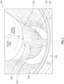
FIG. 3 , a schematic illustration of agas turbine engine 300 is shown. The view shown inFIG. 3 is a partial isometric illustration of thebypass flow path 326 of thegas turbine engine 300. Thegas turbine engine 300 may be substantially similar to that shown and described above. Thegas turbine engine 300 includes anacelle 302 and acore housing 318 that are fixedly connected by alower bifurcation structure 322. As shown, thecore housing 318 has alow point 334 where fluids of core components within thecore housing 318 may collect (e.g., gravitational or geometric low point of the core housing 318). In this illustration adrainage hole 330 is arranged to extract and remove the fluid from thecore housing 318. Thedrainage hole 330, as shown, is located proximate thelow point 334 of thecore housing 318. Thecore housing 318 further includes ahousing aperture 332, which may be configured as an outlet or vent or may be configured as an inlet or scoop (e.g., depending on the specific engine configuration). - As shown, the
drainage hole 330 is located upstream of thehousing aperture 332. Thus, fluid that may drain from and through thedrainage hole 330 may flow aftward toward thehousing aperture 332. Without a redirection device of the present disclosure, the fluid could be reintroduced into the interior of thecore housing 318, which is undesirable. Accordingly, a redirection device may be formed about thedrainage hole 330 to redirect such drained fluid such that it does not reenter thecore housing 318 through thehousing aperture 332. It will be appreciated thatFIG. 3 is merely illustrative, and is not to be limiting. For example, the number ofdrainage holes 330 and/or the number ofhousing apertures 332, and the locations thereof, may be varied and may be dependent, in part, upon a given engine configuration. - Turning now to
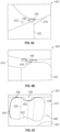
FIGS. 4A-4C , schematic illustrations of agas turbine engine 400 having aredirection device 436 in accordance with an embodiment of the present disclosure are shown.FIG. 4A is a partial isometric illustration of acore housing 418 with alower bifurcation structure 422 extending therefrom (and connecting thecore housing 418 to a nacelle, as shown and described above).FIGS. 4B-4C are enlarged illustrations of theredirection device 436 as mounted to an exterior of thecore housing 418. - As shown in
FIG. 4A , thecore housing 418 includes adrainage hole 430 and ahousing aperture 432. Thehousing aperture 432 is located downstream from thedrainage hole 430 and may provide for an inlet or an outlet of air to core components within thecore housing 418, as described above. Theredirection device 436 is mounted, affixed, or otherwise attached to the core housing 418 (or may be integrally formed therewith) and positioned about thedrainage hole 430. For example, in some embodiments, theredirection device 436 may be a sheet metal component that is soldered, welded, or otherwise affixed to an exterior surface of thecore housing 418. In some embodiments, adhesives or other bonding mechanisms may be employed. Further, in some embodiments, fasteners or other mechanical fixing mechanisms may be employed. Still, in other embodiments, theredirection device 436 may be formed of machined material of thecore housing 418, or may be stamped or otherwise formed. Further still, thecore housing 418 may be additively manufactured to have theredirection device 436 formed therewith. In some embodiments, the redirection device may be formed from the same material as the core housing, and in other embodiments, the material of the redirection device may be different from that material of the core housing. - In the illustrative embodiments of
FIGS. 4A-4C , theredirection device 436 has achannel body 438 that extends between achannel inlet 440 and a channel outlet 442. Thechannel body 438 also has mountingelements 444 extending therefrom to enable mounting to ahousing surface 446 of thecore housing 418. Thechannel body 438 defines achannel 448 or fluid path for directing flow therethrough. Thechannel inlet 440 is arranged proximate thedrainage hole 430 such that fluid flowing through thedrainage hole 430 will enter the channel 448 (shown inFIG. 4B ) and flow along and/or through thechannel 448 and exit the channel outlet 442. As shown inFIG. 4A , theredirection device 436 is arranged to ensure redirection of any fluid away from thehousing aperture 432. - Turning now to
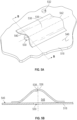
FIGS. 5A-5B , schematic illustrations of aredirection device 536 are shown. Theredirection device 536 is mountable and/or part of acore housing 518, as shown and described above. Specifically, in this non-limiting illustrative embodiment, theredirection device 536 is mounted to and affixed to ahousing surface 546 of thecore housing 518.FIG. 5A illustrates an isometric view of theredirection device 536 andFIG. 5B illustrates a cross-sectional illustration of theredirection device 536 as viewed along the line B-B shown inFIG. 5A . - The
redirection device 536 has achannel body 538 extending between achannel inlet 540 and achannel outlet 542. Theredirection device 536 is positioned such that thechannel inlet 540 is located proximate to, and at least partially covering, adrainage hole 530 formed in thecore housing 518. The position and arrangement of theredirection device 536 is such that theredirection device 536 can receive, channel, and direct fluids from thedrainage hole 530 away from ahousing aperture 532. Thehousing aperture 532 may be an inlet or outlet for air or other fluids and may be configured for enabling a cooling process associated with one or more core components housed within thecore housing 518. - As shown in
FIG. 5B , theredirection device 536 defines achannel 548 through which fluid may be directed. Fluid may enter thechannel 548 from thedrainage hole 530 at achannel inlet 540 and flow along thechannel body 538 toward achannel outlet 542. The fluid may then exit thechannel outlet 542 and flow along thehousing surface 546, but will not interact with (e.g., enter) thehousing aperture 532. InFIG. 5A , thechannel outlet 542 is shown approximately even with thehousing aperture 532, however, such arrangement is not to be limiting. In some embodiments, the location of the channel outlet 542 (and thus the length of the channel body 538) may be located downstream of thehousing aperture 532. In other embodiments, thechannel outlet 542 may be arranged upstream of thehousing aperture 532, but the arrangement and configuration of theredirection device 536 is such that fluid flowing from thedrainage hole 530 is directed away from thehousing aperture 532, thus preventing any such fluids from entering into thecore housing 518 through thehousing aperture 532. - Turning now to
FIG. 6 , an alternative configuration of aredirection device 636 in accordance with an embodiment of the present disclosure is shown. Theredirection device 636 may be similar in structure and function to that shown and described above. In this embodiment, theredirection device 636 includes afirst section 638a and asecond section 638b forming a channel body of theredirection device 636. In this illustration, thefirst section 638a is arranged proximate and at least partially covering adrainage hole 630 formed in acore housing 618. Thefirst section 638a of the channel body defines, in part, achannel inlet 640. Fluid entering theredirection device 636 from thedrainage hole 630 will enter thefirst section 638a and flow toward thesecond section 638b. Thesecond section 638b is arranged to redirect a fluid flow such that fluid exiting theredirection device 636 will be directed away from ahousing aperture 632, as described above. The fluid will then exit theredirection device 636 through achannel outlet 642, which is defined by thesecond section 638b of the channel body. - In this non-limiting, illustrative embodiment, the
redirection device 636 is formed from twodistinct sections first section 638a extends in a firstaxial direction 650a and thesecond section 638b extends in a secondaxial direction 650b. The selection of the first and secondaxial directions axial direction 650a may be selected to minimize entrance drag at thechannel inlet 640, and the secondaxial direction 650b may be selected to ensure no fluid exiting theredirection device 636 will interact with (e.g., enter) thehousing aperture 632. As such, the firstaxial direction 650a may be different than the secondaxial direction 650b. Although shown illustratively as twoseparate sections - Turning now to
FIG. 7 , an alternative configuration of aredirection device 736 in accordance with an embodiment of the present disclosure is shown. Theredirection device 736 may be similar in structure and function to that shown and described above. In this embodiment, theredirection device 736 includes a taperedchannel body 738. Thetaper channel body 738 extends between achannel inlet 740 and achannel outlet 742. Theredirection device 736 is mounted to ahousing surface 746 of acore housing 718. Thechannel inlet 740 is arranged proximate to and at least partially covering adrainage hole 730, as described above. - As shown, the
channel inlet 740 of thechannel body 738 has an inlet height HI as defined from thehousing surface 746 of thecore housing 718. Thechannel outlet 742 of thechannel body 738 has an outlet height HO as defined from thehousing surface 746 of thecore housing 718. In this illustrative embodiment, the outlet height HO is greater than the inlet height HI, thus creating atapered channel body 738. The taper of thechannel body 738 may aid in the flow and directing of a fluid received from thedrainage hole 730. - Turning now to
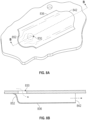
FIGS. 8A-8B , an alternative configuration of aredirection device 836 in accordance with an embodiment of the present disclosure is shown. Theredirection device 836 may be similar in structure and function to that shown and described above. In this embodiment, theredirection device 836 includes aclosed channel inlet 852. Theclosed channel inlet 852 may be configured to minimize drag at theclosed channel inlet 852. Achannel outlet 842 may remain open, and a suction force generated by airflow at thechannel outlet 842 may, in part, cause a fluid from adrainage hole 830 to flow through theredirection device 836 and be directed away from a housing aperture, as described above. - Although shown and described with a limited number of embodiments, those of skill in the art will appreciate that combination of the features of various embodiments may be implemented without departing from the scope of the present disclosure. For example, a curved or two-axis, tapered redirection device with a closed channel inlet may be implemented. Further, other variations may be implemented without departing from the scope of the present disclosure. For example, a taper in the opposing direction to that shown in
FIG. 7 may be employed. Further, a substantially closed channel outlet may be employed, with a hole formed in a surface of the redirection device, the hole arranged to provide an outlet for fluid within the redirection device. - Further, in some embodiments, the cross-sectional area of the channel (e.g.,
channel 548 shown inFIG. 5B ) may be configured with a specific cross-sectional area related to the area of the drainage hole (e.g.,drainage hole 530 shown inFIG. 5B ). For example, in one non-limiting embodiments, the cross-sectional area of the channel may be 0.6 times (or greater than) the cross-sectional area of the drainage hole. It will be appreciated that the cross-sectional area of the channel will be the area shown inFIG. 5B , and the cross-sectional area of the drainage hole will be equal to A = πr 2, where r is the radius of the drainage hole. - Advantageously, embodiments described herein provide for improved drainage of fluids from core components of a gas turbine engine. Advantageously, embodiments described here can allow for optimum or desired core compartment ventilation holes and scoops (i.e., housing apertures) while mitigating risks associated with re-injection of fluids that drain from the core components.
- As used herein, the term "about" is intended to include the degree of error associated with measurement of the particular quantity based upon the equipment available at the time of filing the application. For example, "about" may include a range of ± 8%, or 5%, or 2% of a given value or other percentage change as will be appreciated by those of skill in the art for the particular measurement and/or dimensions referred to herein.
- The terminology used herein is for the purpose of describing particular embodiments only and is not intended to be limiting of the present disclosure. As used herein, the singular forms "a," "an," and "the" are intended to include the plural forms as well, unless the context clearly indicates otherwise. It will be further understood that the terms "comprises" and/or "comprising," when used in this specification, specify the presence of stated features, integers, steps, operations, elements, and/or components, but do not preclude the presence or addition of one or more other features, integers, steps, operations, element components, and/or groups thereof. It should be appreciated that relative positional terms such as "forward," "aft," "upper," "lower," "above," "below," "radial," "axial," "circumferential," and the like are with reference to normal operational attitude and should not be considered otherwise limiting.
- While the present disclosure has been described with reference to an illustrative embodiment or embodiments, it will be understood by those skilled in the art that various changes may be made without departing from the scope of the present disclosure which is defined in the appended claims.
Claims (15)
- A core housing (218, 318, 418, 518, 618, 718) for a gas turbine engine, the core housing comprising:a housing surface (446, 546, 746) defining an exterior surface of the core housing;characterized in that the core housing further comprises:a housing aperture (232, 332, 432, 532, 632) arranged on the housing surface (446, 546, 746), the housing aperture configured to enable fluid communication between an external environment and an interior of the core housing (218, 318, 418, 518, 618, 718);a drainage hole (230, 330, 430, 530, 630, 730, 830) arranged upstream relative to the housing aperture (232, 332, 432, 532, 632), the drainage hole configured to enable draining of a fluid from an interior of the core housing to the external environment; anda redirection device (436, 536, 636, 736, 836) arranged to receive a fluid from the drainage hole (230, 330, 430, 530, 630, 730, 830) and direct such fluid away from the housing aperture (232, 332, 432, 532, 632).
- The core housing of claim 1, wherein the redirection device (436, 536, 636, 736, 836) is mounted to the housing surface (446, 546, 746).
- The core housing of claim 1, wherein the redirection device (436, 536, 636, 736, 836) is integrally formed with the core housing (218, 318, 418, 518, 618, 718).
- The core housing of claim 1, 2 or 3, wherein the redirection device (436, 536, 636, 736, 836) has a channel body (438, 538, 638, 738) defining a channel (448, 548) extending between a channel inlet (440, 540, 640, 740) and a channel outlet (442, 542, 642, 742, 842), optionally wherein the channel inlet is arranged proximate the drainage hole (230, 330, 430, 530, 630, 730, 830) and at least partially covering the drainage hole.
- The core housing of claim 4, wherein the channel inlet is a closed channel inlet (852).
- The core housing of claim 4 or 5, wherein the channel body (438, 538, 638, 738) tapers from the channel inlet to the channel outlet, optionally wherein the channel inlet (740) has an inlet height (HI) defined from the housing surface (746) and the channel outlet (742) has an outlet height (HO) defined from the housing surface (746), wherein the inlet height is less than the outlet height.
- The core housing of claim 4, 5 or 6, wherein the channel body (638) comprises a first section (638a) and a second section (638b), wherein the first section includes the channel inlet (640) and the second section includes the channel outlet (642).
- The core housing of claim 7, wherein the first section (638a) extends in a first axial direction (650a) and the second section (638b) extends in a second axial direction (650b), wherein the first axial direction is different from the second axial direction or wherein the first section and the second section form a continuous, curved channel body.
- The core housing any of claims 4 to 8, wherein a cross-sectional area of the channel (448, 548) is equal to or greater than 0.6 times a cross-sectional area of the drainage hole (230, 330, 430, 530, 630, 730, 830).
- The core housing of any preceding claim, wherein the redirection device (436, 536, 636, 736, 836) is formed from the same material as the core housing, or wherein the redirection device (436, 536, 636, 736, 836) is formed from a material different than the core housing.
- The core housing of any preceding claim, wherein the redirection device (436, 536, 636, 736, 836) is attached to the housing surface (446, 546, 746) by at least one of an adhesive, bonding, welding, and a mechanical fastener.
- The core housing of any preceding claim, wherein the redirection device (436, 536, 636, 736, 836) is mounted to the housing surface at at least one of a gravitational low point and a geometric low point of the core housing.
- The core housing of any preceding claim, further comprising one or more core components (206) installed within the core housing, optionally wherein the one or more core components (206) comprise a gas turbine engine.
- A gas turbine engine (200, 300, 400) comprising:a core housing (218, 318, 418, 518, 618, 718) as claimed in any preceding claima nacelle (202, 302) arranged about the core housing; anda bifurcation structure (222, 224; 332) extending between and connecting the core housing to the nacelle, wherein the core housing is mounted within the nacelle by at least the bifurcation structure,wherein the redirection device (436, 536, 636, 736, 836) is positioned proximate a juncture between the bifurcation structure and the core housing.
- The gas turbine engine of claim 14, wherein the external environment is a bypass flow path (226, 326) defined between the housing surface and an interior surface of the nacelle.
Applications Claiming Priority (1)
| Application Number | Priority Date | Filing Date | Title |
|---|---|---|---|
| US16/263,268 US11028779B2 (en) | 2019-01-31 | 2019-01-31 | Gas turbine engine bypass drainage systems |
Publications (2)
| Publication Number | Publication Date |
|---|---|
| EP3690197A1 EP3690197A1 (en) | 2020-08-05 |
| EP3690197B1 true EP3690197B1 (en) | 2023-04-26 |
Family
ID=69467322
Family Applications (1)
| Application Number | Title | Priority Date | Filing Date |
|---|---|---|---|
| EP20155000.1A Active EP3690197B1 (en) | 2019-01-31 | 2020-01-31 | Gas turbine engine bypass drainage system |
Country Status (2)
| Country | Link |
|---|---|
| US (1) | US11028779B2 (en) |
| EP (1) | EP3690197B1 (en) |
Families Citing this family (1)
| Publication number | Priority date | Publication date | Assignee | Title |
|---|---|---|---|---|
| US12378888B1 (en) * | 2024-02-01 | 2025-08-05 | Rtx Corporation | Airfoil-mounted acoustic resonator array for gas turbine engine component |
Family Cites Families (11)
| Publication number | Priority date | Publication date | Assignee | Title |
|---|---|---|---|---|
| FR1452652A (en) | 1965-06-14 | 1966-04-15 | Snecma | Improvements to articulated joints of jet thruster housings |
| US4163366A (en) | 1977-05-23 | 1979-08-07 | Avco Corporation | Apparatus for disposal of leaking fluids in a turbofan engine |
| US5054282A (en) * | 1989-02-28 | 1991-10-08 | United Technologies Corporation | Drain assembly |
| US5104069A (en) | 1990-10-29 | 1992-04-14 | The Boeing Company | Apparatus and method for ejecting matter from an aircraft |
| FR2864031B1 (en) | 2003-12-18 | 2006-03-31 | Airbus France | DRAIN IN PARTICULAR FOR MATT REACTOR SUPPORT |
| GB0908540D0 (en) | 2009-05-19 | 2009-06-24 | Rolls Royce Plc | A gas turbine engine having a nacelle and a breather duct |
| FR2968062B1 (en) | 2010-11-26 | 2012-11-16 | Snecma | OIL DRAINING DEVICE AND TURBOMACHINE COMPRISING SUCH A DEVICE |
| JP6419437B2 (en) | 2014-02-28 | 2018-11-07 | 三菱航空機株式会社 | Aircraft engine pylon and aircraft |
| EP2918787B1 (en) * | 2014-03-12 | 2017-10-18 | Rolls-Royce Deutschland Ltd & Co KG | Flow guiding system and rotary combustion engine |
| US10024188B2 (en) * | 2015-03-02 | 2018-07-17 | Rohr, Inc. | High temperature composite inner fixed structure |
| US10808577B2 (en) * | 2017-03-28 | 2020-10-20 | The Boeing Company | Aerodynamic drainage device |
-
2019
- 2019-01-31 US US16/263,268 patent/US11028779B2/en active Active
-
2020
- 2020-01-31 EP EP20155000.1A patent/EP3690197B1/en active Active
Also Published As
| Publication number | Publication date |
|---|---|
| US11028779B2 (en) | 2021-06-08 |
| EP3690197A1 (en) | 2020-08-05 |
| US20200248628A1 (en) | 2020-08-06 |
Similar Documents
| Publication | Publication Date | Title |
|---|---|---|
| EP3045672B1 (en) | Cooling passages for a mid-turbine frame | |
| EP3045671B1 (en) | Cooling passages for a mid-turbine frame | |
| EP3045668B1 (en) | Cooling passages for a mid-turbine frame | |
| EP3029298B1 (en) | Turbomachine air inlets with liquid separation | |
| EP3896264B1 (en) | Gas turbine engine with partial arc gutter | |
| EP3318718B1 (en) | Fan for a gas turbine engine an corresponding method of securing fan blades to a rotor of a fan of a gas turbine engine | |
| EP3246523B1 (en) | Cooled blade outer air seal | |
| EP2993304B1 (en) | Gas turbine engine component with film cooling hole | |
| EP3323989B1 (en) | Component for a gas turbine engine, corresponding gas turbine engine and method of fabricating | |
| EP2971702B1 (en) | Bleed valve assembly | |
| EP3056680B1 (en) | Leakage air systems for turbomachines | |
| EP3502563B1 (en) | Apparatus for mitigating particulate accumulation on a combustor wall of a gas turbine | |
| EP3428411B1 (en) | Gas turbine engine and corresponding method of cooling | |
| EP3045669B1 (en) | Cooling passages for a mid-turbine frame | |
| EP3054102B1 (en) | A mid-turbine frame assembly with cooling passages for a gas turbine engine | |
| EP3492813B1 (en) | Apparatus for mitigating particulate accumulation on a shell of a combustor of a gas turbine engine | |
| EP3045670B1 (en) | Cooling passages for a mid-turbine frame | |
| EP3690197B1 (en) | Gas turbine engine bypass drainage system | |
| EP3045666B1 (en) | Airfoil platform with cooling feed orifices | |
| EP3502564B1 (en) | Combustor shell mitigating particulate accumulation on the bulkhead of a gas turbine engine | |
| EP3859212B1 (en) | Combustor shell with shaped impingement holes | |
| EP3650646B1 (en) | Airfoil with baffle showerhead and cooling passage network having aft inlet | |
| EP3575688B1 (en) | Design and manufacturing process for directed impingement punched plates | |
| EP2933439B1 (en) | Seal plate with fluid bypass control | |
| EP3643887B1 (en) | Gas turbine engine seal assemblies |
Legal Events
| Date | Code | Title | Description |
|---|---|---|---|
| PUAI | Public reference made under article 153(3) epc to a published international application that has entered the european phase |
Free format text: ORIGINAL CODE: 0009012 |
|
| STAA | Information on the status of an ep patent application or granted ep patent |
Free format text: STATUS: THE APPLICATION HAS BEEN PUBLISHED |
|
| AK | Designated contracting states |
Kind code of ref document: A1 Designated state(s): AL AT BE BG CH CY CZ DE DK EE ES FI FR GB GR HR HU IE IS IT LI LT LU LV MC MK MT NL NO PL PT RO RS SE SI SK SM TR |
|
| AX | Request for extension of the european patent |
Extension state: BA ME |
|
| STAA | Information on the status of an ep patent application or granted ep patent |
Free format text: STATUS: REQUEST FOR EXAMINATION WAS MADE |
|
| 17P | Request for examination filed |
Effective date: 20210203 |
|
| RBV | Designated contracting states (corrected) |
Designated state(s): AL AT BE BG CH CY CZ DE DK EE ES FI FR GB GR HR HU IE IS IT LI LT LU LV MC MK MT NL NO PL PT RO RS SE SI SK SM TR |
|
| RAP1 | Party data changed (applicant data changed or rights of an application transferred) |
Owner name: RAYTHEON TECHNOLOGIES CORPORATION |
|
| GRAP | Despatch of communication of intention to grant a patent |
Free format text: ORIGINAL CODE: EPIDOSNIGR1 |
|
| STAA | Information on the status of an ep patent application or granted ep patent |
Free format text: STATUS: GRANT OF PATENT IS INTENDED |
|
| INTG | Intention to grant announced |
Effective date: 20221104 |
|
| GRAS | Grant fee paid |
Free format text: ORIGINAL CODE: EPIDOSNIGR3 |
|
| GRAA | (expected) grant |
Free format text: ORIGINAL CODE: 0009210 |
|
| STAA | Information on the status of an ep patent application or granted ep patent |
Free format text: STATUS: THE PATENT HAS BEEN GRANTED |
|
| AK | Designated contracting states |
Kind code of ref document: B1 Designated state(s): AL AT BE BG CH CY CZ DE DK EE ES FI FR GB GR HR HU IE IS IT LI LT LU LV MC MK MT NL NO PL PT RO RS SE SI SK SM TR |
|
| REG | Reference to a national code |
Ref country code: GB Ref legal event code: FG4D |
|
| REG | Reference to a national code |
Ref country code: CH Ref legal event code: EP |
|
| REG | Reference to a national code |
Ref country code: DE Ref legal event code: R096 Ref document number: 602020010005 Country of ref document: DE |
|
| REG | Reference to a national code |
Ref country code: AT Ref legal event code: REF Ref document number: 1562961 Country of ref document: AT Kind code of ref document: T Effective date: 20230515 |
|
| REG | Reference to a national code |
Ref country code: IE Ref legal event code: FG4D |
|
| P01 | Opt-out of the competence of the unified patent court (upc) registered |
Effective date: 20230603 |
|
| REG | Reference to a national code |
Ref country code: LT Ref legal event code: MG9D |
|
| REG | Reference to a national code |
Ref country code: NL Ref legal event code: MP Effective date: 20230426 |
|
| REG | Reference to a national code |
Ref country code: AT Ref legal event code: MK05 Ref document number: 1562961 Country of ref document: AT Kind code of ref document: T Effective date: 20230426 |
|
| PG25 | Lapsed in a contracting state [announced via postgrant information from national office to epo] |
Ref country code: NL Free format text: LAPSE BECAUSE OF FAILURE TO SUBMIT A TRANSLATION OF THE DESCRIPTION OR TO PAY THE FEE WITHIN THE PRESCRIBED TIME-LIMIT Effective date: 20230426 |
|
| PG25 | Lapsed in a contracting state [announced via postgrant information from national office to epo] |
Ref country code: SE Free format text: LAPSE BECAUSE OF FAILURE TO SUBMIT A TRANSLATION OF THE DESCRIPTION OR TO PAY THE FEE WITHIN THE PRESCRIBED TIME-LIMIT Effective date: 20230426 Ref country code: PT Free format text: LAPSE BECAUSE OF FAILURE TO SUBMIT A TRANSLATION OF THE DESCRIPTION OR TO PAY THE FEE WITHIN THE PRESCRIBED TIME-LIMIT Effective date: 20230828 Ref country code: NO Free format text: LAPSE BECAUSE OF FAILURE TO SUBMIT A TRANSLATION OF THE DESCRIPTION OR TO PAY THE FEE WITHIN THE PRESCRIBED TIME-LIMIT Effective date: 20230726 Ref country code: ES Free format text: LAPSE BECAUSE OF FAILURE TO SUBMIT A TRANSLATION OF THE DESCRIPTION OR TO PAY THE FEE WITHIN THE PRESCRIBED TIME-LIMIT Effective date: 20230426 Ref country code: AT Free format text: LAPSE BECAUSE OF FAILURE TO SUBMIT A TRANSLATION OF THE DESCRIPTION OR TO PAY THE FEE WITHIN THE PRESCRIBED TIME-LIMIT Effective date: 20230426 |
|
| RAP4 | Party data changed (patent owner data changed or rights of a patent transferred) |
Owner name: RTX CORPORATION |
|
| PG25 | Lapsed in a contracting state [announced via postgrant information from national office to epo] |
Ref country code: RS Free format text: LAPSE BECAUSE OF FAILURE TO SUBMIT A TRANSLATION OF THE DESCRIPTION OR TO PAY THE FEE WITHIN THE PRESCRIBED TIME-LIMIT Effective date: 20230426 Ref country code: PL Free format text: LAPSE BECAUSE OF FAILURE TO SUBMIT A TRANSLATION OF THE DESCRIPTION OR TO PAY THE FEE WITHIN THE PRESCRIBED TIME-LIMIT Effective date: 20230426 Ref country code: LV Free format text: LAPSE BECAUSE OF FAILURE TO SUBMIT A TRANSLATION OF THE DESCRIPTION OR TO PAY THE FEE WITHIN THE PRESCRIBED TIME-LIMIT Effective date: 20230426 Ref country code: LT Free format text: LAPSE BECAUSE OF FAILURE TO SUBMIT A TRANSLATION OF THE DESCRIPTION OR TO PAY THE FEE WITHIN THE PRESCRIBED TIME-LIMIT Effective date: 20230426 Ref country code: IS Free format text: LAPSE BECAUSE OF FAILURE TO SUBMIT A TRANSLATION OF THE DESCRIPTION OR TO PAY THE FEE WITHIN THE PRESCRIBED TIME-LIMIT Effective date: 20230826 Ref country code: HR Free format text: LAPSE BECAUSE OF FAILURE TO SUBMIT A TRANSLATION OF THE DESCRIPTION OR TO PAY THE FEE WITHIN THE PRESCRIBED TIME-LIMIT Effective date: 20230426 Ref country code: GR Free format text: LAPSE BECAUSE OF FAILURE TO SUBMIT A TRANSLATION OF THE DESCRIPTION OR TO PAY THE FEE WITHIN THE PRESCRIBED TIME-LIMIT Effective date: 20230727 |
|
| PG25 | Lapsed in a contracting state [announced via postgrant information from national office to epo] |
Ref country code: FI Free format text: LAPSE BECAUSE OF FAILURE TO SUBMIT A TRANSLATION OF THE DESCRIPTION OR TO PAY THE FEE WITHIN THE PRESCRIBED TIME-LIMIT Effective date: 20230426 |
|
| PG25 | Lapsed in a contracting state [announced via postgrant information from national office to epo] |
Ref country code: SK Free format text: LAPSE BECAUSE OF FAILURE TO SUBMIT A TRANSLATION OF THE DESCRIPTION OR TO PAY THE FEE WITHIN THE PRESCRIBED TIME-LIMIT Effective date: 20230426 |
|
| REG | Reference to a national code |
Ref country code: DE Ref legal event code: R097 Ref document number: 602020010005 Country of ref document: DE |
|
| PG25 | Lapsed in a contracting state [announced via postgrant information from national office to epo] |
Ref country code: SM Free format text: LAPSE BECAUSE OF FAILURE TO SUBMIT A TRANSLATION OF THE DESCRIPTION OR TO PAY THE FEE WITHIN THE PRESCRIBED TIME-LIMIT Effective date: 20230426 Ref country code: SK Free format text: LAPSE BECAUSE OF FAILURE TO SUBMIT A TRANSLATION OF THE DESCRIPTION OR TO PAY THE FEE WITHIN THE PRESCRIBED TIME-LIMIT Effective date: 20230426 Ref country code: RO Free format text: LAPSE BECAUSE OF FAILURE TO SUBMIT A TRANSLATION OF THE DESCRIPTION OR TO PAY THE FEE WITHIN THE PRESCRIBED TIME-LIMIT Effective date: 20230426 Ref country code: EE Free format text: LAPSE BECAUSE OF FAILURE TO SUBMIT A TRANSLATION OF THE DESCRIPTION OR TO PAY THE FEE WITHIN THE PRESCRIBED TIME-LIMIT Effective date: 20230426 Ref country code: DK Free format text: LAPSE BECAUSE OF FAILURE TO SUBMIT A TRANSLATION OF THE DESCRIPTION OR TO PAY THE FEE WITHIN THE PRESCRIBED TIME-LIMIT Effective date: 20230426 Ref country code: CZ Free format text: LAPSE BECAUSE OF FAILURE TO SUBMIT A TRANSLATION OF THE DESCRIPTION OR TO PAY THE FEE WITHIN THE PRESCRIBED TIME-LIMIT Effective date: 20230426 |
|
| PLBE | No opposition filed within time limit |
Free format text: ORIGINAL CODE: 0009261 |
|
| STAA | Information on the status of an ep patent application or granted ep patent |
Free format text: STATUS: NO OPPOSITION FILED WITHIN TIME LIMIT |
|
| 26N | No opposition filed |
Effective date: 20240129 |
|
| PG25 | Lapsed in a contracting state [announced via postgrant information from national office to epo] |
Ref country code: SI Free format text: LAPSE BECAUSE OF FAILURE TO SUBMIT A TRANSLATION OF THE DESCRIPTION OR TO PAY THE FEE WITHIN THE PRESCRIBED TIME-LIMIT Effective date: 20230426 |
|
| PG25 | Lapsed in a contracting state [announced via postgrant information from national office to epo] |
Ref country code: SI Free format text: LAPSE BECAUSE OF FAILURE TO SUBMIT A TRANSLATION OF THE DESCRIPTION OR TO PAY THE FEE WITHIN THE PRESCRIBED TIME-LIMIT Effective date: 20230426 Ref country code: IT Free format text: LAPSE BECAUSE OF FAILURE TO SUBMIT A TRANSLATION OF THE DESCRIPTION OR TO PAY THE FEE WITHIN THE PRESCRIBED TIME-LIMIT Effective date: 20230426 |
|
| PG25 | Lapsed in a contracting state [announced via postgrant information from national office to epo] |
Ref country code: MC Free format text: LAPSE BECAUSE OF FAILURE TO SUBMIT A TRANSLATION OF THE DESCRIPTION OR TO PAY THE FEE WITHIN THE PRESCRIBED TIME-LIMIT Effective date: 20230426 |
|
| PG25 | Lapsed in a contracting state [announced via postgrant information from national office to epo] |
Ref country code: MC Free format text: LAPSE BECAUSE OF FAILURE TO SUBMIT A TRANSLATION OF THE DESCRIPTION OR TO PAY THE FEE WITHIN THE PRESCRIBED TIME-LIMIT Effective date: 20230426 |
|
| REG | Reference to a national code |
Ref country code: CH Ref legal event code: PL |
|
| PG25 | Lapsed in a contracting state [announced via postgrant information from national office to epo] |
Ref country code: LU Free format text: LAPSE BECAUSE OF NON-PAYMENT OF DUE FEES Effective date: 20240131 |
|
| PG25 | Lapsed in a contracting state [announced via postgrant information from national office to epo] |
Ref country code: LU Free format text: LAPSE BECAUSE OF NON-PAYMENT OF DUE FEES Effective date: 20240131 |
|
| PG25 | Lapsed in a contracting state [announced via postgrant information from national office to epo] |
Ref country code: BE Free format text: LAPSE BECAUSE OF NON-PAYMENT OF DUE FEES Effective date: 20240131 |
|
| PG25 | Lapsed in a contracting state [announced via postgrant information from national office to epo] |
Ref country code: CH Free format text: LAPSE BECAUSE OF NON-PAYMENT OF DUE FEES Effective date: 20240131 |
|
| PG25 | Lapsed in a contracting state [announced via postgrant information from national office to epo] |
Ref country code: CH Free format text: LAPSE BECAUSE OF NON-PAYMENT OF DUE FEES Effective date: 20240131 Ref country code: BE Free format text: LAPSE BECAUSE OF NON-PAYMENT OF DUE FEES Effective date: 20240131 |
|
| REG | Reference to a national code |
Ref country code: BE Ref legal event code: MM Effective date: 20240131 |
|
| PG25 | Lapsed in a contracting state [announced via postgrant information from national office to epo] |
Ref country code: BG Free format text: LAPSE BECAUSE OF FAILURE TO SUBMIT A TRANSLATION OF THE DESCRIPTION OR TO PAY THE FEE WITHIN THE PRESCRIBED TIME-LIMIT Effective date: 20230426 |
|
| PG25 | Lapsed in a contracting state [announced via postgrant information from national office to epo] |
Ref country code: BG Free format text: LAPSE BECAUSE OF FAILURE TO SUBMIT A TRANSLATION OF THE DESCRIPTION OR TO PAY THE FEE WITHIN THE PRESCRIBED TIME-LIMIT Effective date: 20230426 |
|
| PG25 | Lapsed in a contracting state [announced via postgrant information from national office to epo] |
Ref country code: IE Free format text: LAPSE BECAUSE OF NON-PAYMENT OF DUE FEES Effective date: 20240131 |
|
| PG25 | Lapsed in a contracting state [announced via postgrant information from national office to epo] |
Ref country code: IE Free format text: LAPSE BECAUSE OF NON-PAYMENT OF DUE FEES Effective date: 20240131 |
|
| PG25 | Lapsed in a contracting state [announced via postgrant information from national office to epo] |
Ref country code: CY Free format text: LAPSE BECAUSE OF FAILURE TO SUBMIT A TRANSLATION OF THE DESCRIPTION OR TO PAY THE FEE WITHIN THE PRESCRIBED TIME-LIMIT; INVALID AB INITIO Effective date: 20200131 |
|
| PG25 | Lapsed in a contracting state [announced via postgrant information from national office to epo] |
Ref country code: HU Free format text: LAPSE BECAUSE OF FAILURE TO SUBMIT A TRANSLATION OF THE DESCRIPTION OR TO PAY THE FEE WITHIN THE PRESCRIBED TIME-LIMIT; INVALID AB INITIO Effective date: 20200131 |
|
| REG | Reference to a national code |
Ref country code: DE Ref legal event code: R081 Ref document number: 602020010005 Country of ref document: DE Owner name: RTX CORPORATION (N.D.GES.D. STAATES DELAWARE),, US Free format text: FORMER OWNER: RAYTHEON TECHNOLOGIES CORPORATION, FARMINGTON, CT, US |
|
| PG25 | Lapsed in a contracting state [announced via postgrant information from national office to epo] |
Ref country code: TR Free format text: LAPSE BECAUSE OF FAILURE TO SUBMIT A TRANSLATION OF THE DESCRIPTION OR TO PAY THE FEE WITHIN THE PRESCRIBED TIME-LIMIT Effective date: 20230426 |
|
| PGFP | Annual fee paid to national office [announced via postgrant information from national office to epo] |
Ref country code: GB Payment date: 20251217 Year of fee payment: 7 |
|
| PGFP | Annual fee paid to national office [announced via postgrant information from national office to epo] |
Ref country code: FR Payment date: 20251217 Year of fee payment: 7 |
|
| PGFP | Annual fee paid to national office [announced via postgrant information from national office to epo] |
Ref country code: DE Payment date: 20251217 Year of fee payment: 7 |