EP3690194B1 - System for active data acquisition management in a gas turbine engine - Google Patents
System for active data acquisition management in a gas turbine engine Download PDFInfo
- Publication number
- EP3690194B1 EP3690194B1 EP19205840.2A EP19205840A EP3690194B1 EP 3690194 B1 EP3690194 B1 EP 3690194B1 EP 19205840 A EP19205840 A EP 19205840A EP 3690194 B1 EP3690194 B1 EP 3690194B1
- Authority
- EP
- European Patent Office
- Prior art keywords
- mems
- sampling rate
- sensor
- controller
- aircraft
- Prior art date
- Legal status (The legal status is an assumption and is not a legal conclusion. Google has not performed a legal analysis and makes no representation as to the accuracy of the status listed.)
- Active
Links
Images

Classifications
-
- F—MECHANICAL ENGINEERING; LIGHTING; HEATING; WEAPONS; BLASTING
- F01—MACHINES OR ENGINES IN GENERAL; ENGINE PLANTS IN GENERAL; STEAM ENGINES
- F01D—NON-POSITIVE DISPLACEMENT MACHINES OR ENGINES, e.g. STEAM TURBINES
- F01D17/00—Regulating or controlling by varying flow
- F01D17/02—Arrangement of sensing elements
-
- F—MECHANICAL ENGINEERING; LIGHTING; HEATING; WEAPONS; BLASTING
- F01—MACHINES OR ENGINES IN GENERAL; ENGINE PLANTS IN GENERAL; STEAM ENGINES
- F01D—NON-POSITIVE DISPLACEMENT MACHINES OR ENGINES, e.g. STEAM TURBINES
- F01D21/00—Shutting-down of machines or engines, e.g. in emergency; Regulating, controlling, or safety means not otherwise provided for
- F01D21/003—Arrangements for testing or measuring
-
- F—MECHANICAL ENGINEERING; LIGHTING; HEATING; WEAPONS; BLASTING
- F01—MACHINES OR ENGINES IN GENERAL; ENGINE PLANTS IN GENERAL; STEAM ENGINES
- F01D—NON-POSITIVE DISPLACEMENT MACHINES OR ENGINES, e.g. STEAM TURBINES
- F01D5/00—Blades; Blade-carrying members; Heating, heat-insulating, cooling or antivibration means on the blades or the members
- F01D5/12—Blades
- F01D5/26—Antivibration means not restricted to blade form or construction or to blade-to-blade connections or to the use of particular materials
-
- F—MECHANICAL ENGINEERING; LIGHTING; HEATING; WEAPONS; BLASTING
- F02—COMBUSTION ENGINES; HOT-GAS OR COMBUSTION-PRODUCT ENGINE PLANTS
- F02C—GAS-TURBINE PLANTS; AIR INTAKES FOR JET-PROPULSION PLANTS; CONTROLLING FUEL SUPPLY IN AIR-BREATHING JET-PROPULSION PLANTS
- F02C9/00—Controlling gas-turbine plants; Controlling fuel supply in air- breathing jet-propulsion plants
-
- G—PHYSICS
- G01—MEASURING; TESTING
- G01H—MEASUREMENT OF MECHANICAL VIBRATIONS OR ULTRASONIC, SONIC OR INFRASONIC WAVES
- G01H1/00—Measuring characteristics of vibrations in solids by using direct conduction to the detector
- G01H1/003—Measuring characteristics of vibrations in solids by using direct conduction to the detector of rotating machines
- G01H1/006—Measuring characteristics of vibrations in solids by using direct conduction to the detector of rotating machines of the rotor of turbo machines
-
- G—PHYSICS
- G01—MEASURING; TESTING
- G01M—TESTING STATIC OR DYNAMIC BALANCE OF MACHINES OR STRUCTURES; TESTING OF STRUCTURES OR APPARATUS, NOT OTHERWISE PROVIDED FOR
- G01M15/00—Testing of engines
- G01M15/14—Testing gas-turbine engines or jet-propulsion engines
-
- H—ELECTRICITY
- H04—ELECTRIC COMMUNICATION TECHNIQUE
- H04L—TRANSMISSION OF DIGITAL INFORMATION, e.g. TELEGRAPHIC COMMUNICATION
- H04L43/00—Arrangements for monitoring or testing data switching networks
- H04L43/02—Capturing of monitoring data
- H04L43/022—Capturing of monitoring data by sampling
- H04L43/024—Capturing of monitoring data by sampling by adaptive sampling
-
- H—ELECTRICITY
- H04—ELECTRIC COMMUNICATION TECHNIQUE
- H04L—TRANSMISSION OF DIGITAL INFORMATION, e.g. TELEGRAPHIC COMMUNICATION
- H04L43/00—Arrangements for monitoring or testing data switching networks
- H04L43/16—Threshold monitoring
-
- H—ELECTRICITY
- H04—ELECTRIC COMMUNICATION TECHNIQUE
- H04L—TRANSMISSION OF DIGITAL INFORMATION, e.g. TELEGRAPHIC COMMUNICATION
- H04L67/00—Network arrangements or protocols for supporting network services or applications
- H04L67/01—Protocols
- H04L67/12—Protocols specially adapted for proprietary or special-purpose networking environments, e.g. medical networks, sensor networks, networks in vehicles or remote metering networks
-
- B—PERFORMING OPERATIONS; TRANSPORTING
- B64—AIRCRAFT; AVIATION; COSMONAUTICS
- B64D—EQUIPMENT FOR FITTING IN OR TO AIRCRAFT; FLIGHT SUITS; PARACHUTES; ARRANGEMENT OR MOUNTING OF POWER PLANTS OR PROPULSION TRANSMISSIONS IN AIRCRAFT
- B64D45/00—Aircraft indicators or protectors not otherwise provided for
- B64D2045/0085—Devices for aircraft health monitoring, e.g. monitoring flutter or vibration
-
- F—MECHANICAL ENGINEERING; LIGHTING; HEATING; WEAPONS; BLASTING
- F05—INDEXING SCHEMES RELATING TO ENGINES OR PUMPS IN VARIOUS SUBCLASSES OF CLASSES F01-F04
- F05D—INDEXING SCHEME FOR ASPECTS RELATING TO NON-POSITIVE-DISPLACEMENT MACHINES OR ENGINES, GAS-TURBINES OR JET-PROPULSION PLANTS
- F05D2260/00—Function
- F05D2260/80—Diagnostics
-
- F—MECHANICAL ENGINEERING; LIGHTING; HEATING; WEAPONS; BLASTING
- F05—INDEXING SCHEMES RELATING TO ENGINES OR PUMPS IN VARIOUS SUBCLASSES OF CLASSES F01-F04
- F05D—INDEXING SCHEME FOR ASPECTS RELATING TO NON-POSITIVE-DISPLACEMENT MACHINES OR ENGINES, GAS-TURBINES OR JET-PROPULSION PLANTS
- F05D2270/00—Control
- F05D2270/30—Control parameters, e.g. input parameters
- F05D2270/334—Vibration measurements
Definitions
- the present disclosure relates generally to aircraft sensor data acquisition, and more specifically to a system and method for actively controlling a data acquisition rate of an aircraft system sensor.
- Gas turbine engines such as those utilized in commercial and military aircraft, include a compressor section that compresses air, a combustor section in which the compressed air is mixed with a fuel and ignited, and a turbine section across which the resultant combustion products are expanded.
- the expansion of the combustion products drives the turbine section to rotate.
- the turbine section is connected to the compressor section via a shaft, the rotation of the turbine section further drives the compressor section to rotate.
- a fan is also connected to the shaft and is driven to rotate via rotation of the turbine as well.
- an engine controller such as a full authority digital engine controller (FADEC) to monitor one or more parameters of the engine operation.
- the parameters can be monitored using sensors configured to detect the parameters.
- the data from the sensors is read at an acquisition rate (alternately referred to as a sampling rate). In some instances, such as when certain vibrational events occur, it can be desirable to read data from the sensor more frequently than the base data acquisition rate.
- FADEC full authority digital engine controller
- a prior art aircraft sensor system and method for operating the same having the features of the preamble to claims 1 and 10 is disclosed in US 2016/178464 .
- a prior art wireless engine monitoring system is also disclosed in US 9,816,897 .
- an aircraft sensor system that includes a first sensor configured to detect a parameter of an aircraft system, a first micro electro-mechanical-system (MEMS) disposed local to a first component within the aircraft system, the first MEMS being communicatively connected to a controller, and being configured to trigger in response to a corresponding parameter exceeding a threshold, and the controller being connected to an output of the first sensor and including a non-transitory memory storing instructions configured to cause the controller to increase a sampling rate of the first sensor to a sampling rate corresponding to the first component for at least a predetermined length of time in response to the first MEMS being triggered.
- MEMS micro electro-mechanical-system
- the first sensor is a vibration sensor.
- the first sensor is disposed on a gas turbine engine housing and is configured to sense a parameter of a gas turbine engine.
- Another preferred embodiment of any of the above described aircraft sensor systems further includes a plurality of MEMS including the first MEMS, with each MEMS in the plurality of MEMS being local to a distinct component from each other MEMS in the plurality of MEMS.
- each MEMS in the plurality of MEMS is connected to the controller and is configured to trigger in response to a corresponding parameter of the component to which the MEMS is local to exceeding a threshold.
- the controller is configured to increase the sampling rate of the first sensor to a sampling rate corresponding to each MEMS in the plurality of MEMS for at least a predetermined length of time in response to the corresponding MEMS being triggered.
- the sampling rate corresponding to each MEMS is distinct from each the sampling rate corresponding to each other MEMS in the plurality of MEMS.
- the sampling rate corresponding to at least two MEMS in the plurality of MEMS is identical.
- each MEMS in the plurality of MEMS has a length in its longest dimension ranging from 20 micrometers to 1 millimeter.
- the predefined length of time has a length in the range of 100-400 ms.
- a method for operating an aircraft sensor system that includes a controller receiving a first signal from a first micro electro-mechanical-system (MEMS) disposed local to a first component, wherein the first signal indicates that a first event has occurred, and the controller increasing a sampling rate of a system sensor from a first sampling rate to a second sampling rate for at least predefined time period in response to receiving the signal.
- MEMS micro electro-mechanical-system
- the second sampling rate is at least sufficient to compensate for a structural vibratory mode of the first component.
- the controller receives a second signal from a second micro electro-mechanical-system (MEMS) disposed local to a second component simultaneous with the first signal, wherein the second signal indicates that a second event has occurred, and the controller increasing the sampling rate of the system sensor from the first sampling rate to a higher of the second sampling rate and a third sampling rate, each of the second sampling rate and the third sampling rate corresponding to one of the first and second component.
- MEMS micro electro-mechanical-system
- the predefined time period begins upon receipt of the first signal.
- the predefined time period begins when the first signal ceases being received.
- the first event is a vibration at the first component exceeding a predetermined threshold.
- FIG. 1 schematically illustrates a gas turbine engine 20.
- the gas turbine engine 20 is disclosed herein as a two-spool turbofan that generally incorporates a fan section 22, a compressor section 24, a combustor section 26 and a turbine section 28.
- the fan section 22 drives air along a bypass flow path B in a bypass duct defined within a nacelle 15, and also drives air along a core flow path C for compression and communication into the combustor section 26 then expansion through the turbine section 28.
- FIG. 1 schematically illustrates a gas turbine engine 20.
- the gas turbine engine 20 is disclosed herein as a two-spool turbofan that generally incorporates a fan section 22, a compressor section 24, a combustor section 26 and a turbine section 28.
- the fan section 22 drives air along a bypass flow path B in a bypass duct defined within a nacelle 15, and also drives air along a core flow path C for compression and communication into the combustor section 26 then expansion through the turbine section 28.
- FIG. 1 schematic
- the exemplary engine 20 generally includes a low speed spool 30 and a high speed spool 32 mounted for rotation about an engine central longitudinal axis A relative to an engine static structure 36 via several bearing systems 38. It should be understood that various bearing systems 38 at various locations may alternatively or additionally be provided, and the location of bearing systems 38 may be varied as appropriate to the application.
- the low speed spool 30 generally includes an inner shaft 40 that interconnects a fan 42, a first (or low) pressure compressor 44 and a first (or low) pressure turbine 46.
- the inner shaft 40 is connected to the fan 42 through a speed change mechanism, which in exemplary gas turbine engine 20 is illustrated as a geared architecture 48 to drive the fan 42 at a lower speed than the low speed spool 30.
- the high speed spool 32 includes an outer shaft 50 that interconnects a second (or high) pressure compressor 52 and a second (or high) pressure turbine 54.
- a combustor 56 is arranged in exemplary gas turbine 20 between the high pressure compressor 52 and the high pressure turbine 54.
- a mid-turbine frame 57 of the engine static structure 36 is arranged generally between the high pressure turbine 54 and the low pressure turbine 46.
- the mid-turbine frame 57 further supports bearing systems 38 in the turbine section 28.
- the inner shaft 40 and the outer shaft 50 are concentric and rotate via bearing systems 38 about the engine central longitudinal axis A which is collinear with their longitudinal axes.
- the core airflow is compressed by the low pressure compressor 44 then the high pressure compressor 52, mixed and burned with fuel in the combustor 56, then expanded over the high pressure turbine 54 and low pressure turbine 46.
- the mid-turbine frame 57 includes airfoils 59 which are in the core airflow path C.
- the turbines 46, 54 rotationally drive the respective low speed spool 30 and high speed spool 32 in response to the expansion.
- gear system 48 may be located aft of combustor section 26 or even aft of turbine section 28, and fan section 22 may be positioned forward or aft of the location of gear system 48.
- the engine 20 in one example is a high-bypass geared aircraft engine.
- the engine 20 bypass ratio is greater than about six (6), with an example embodiment being greater than about ten (10)
- the geared architecture 48 is an epicyclic gear train, such as a planetary gear system or other gear system, with a gear reduction ratio of greater than about 2.3
- the low pressure turbine 46 has a pressure ratio that is greater than about five.
- the engine 20 bypass ratio is greater than about ten (10:1)
- the fan diameter is significantly larger than that of the low pressure compressor 44
- the low pressure turbine 46 has a pressure ratio that is greater than about five 5:1.
- Low pressure turbine 46 pressure ratio is pressure measured prior to inlet of low pressure turbine 46 as related to the pressure at the outlet of the low pressure turbine 46 prior to an exhaust nozzle.
- the geared architecture 48 may be an epicycle gear train, such as a planetary gear system or other gear system, with a gear reduction ratio of greater than about 2.3:1. It should be understood, however, that the above parameters are only exemplary of one embodiment of a geared architecture engine and that the present invention is applicable to other gas turbine engines including direct drive turbofans.
- the fan section 22 of the engine 20 is designed for a particular flight condition -- typically cruise at about 0.8 Mach and about 35,000 feet (10,668 meters).
- the flight condition of 0.8 Mach and 35,000 ft (10,668 meters), with the engine at its best fuel consumption - also known as "bucket cruise Thrust Specific Fuel Consumption ('TSFC')" - is the industry standard parameter of lbm of fuel being burned divided by lbf of thrust the engine produces at that minimum point.
- "Low fan pressure ratio” is the pressure ratio across the fan blade alone, without a Fan Exit Guide Vane (“FEGV”) system.
- the low fan pressure ratio as disclosed herein according to one non-limiting embodiment is less than about 1.45.
- the "Low corrected fan tip speed" as disclosed herein according to one non-limiting embodiment is less than about 1150 ft / second (350.5 meters/second).
- the exemplary gas turbine engine 20 includes a vibrational sensor 90 positioned in or on the exterior casing of the engine 20.
- the vibrational sensor 90 is configured to detect an overall magnitude of vibrations within the engine 20 at any given time. Due to its position, the isolation ability of the vibration sensor 90 is limited to distinct shafts and has limited capability to distinguish between related components.
- the vibrational sensor 90 is connected to a controller 92, such as a full authority digital engine controller (FADEC).
- the controller 92 can be a general aircraft controller, a dedicated sensor controller, or any other type of controller configured to receive and interpret signals from the vibrational sensor 90, and from one or more micro-electromechanical-systems (MEMS).
- MEMS micro-electromechanical-systems
- MEMS micro-electro-mechanical-system
- a component such as the MEMS 94, is "local to" a system when the component is either positioned on or in the component to which it is local, or is in a position where vibrational forces on the component are dominated by the vibrational forces on the system to which the component is local.
- Each of the MEMS 94 is connected to the controller 92 either via a wireless connection, or a direct wired connection depending on the particular characteristics of the specific engine 20.
- the MEMS 94 can be positioned local to any number of different components including, but not limited to, an accessory gearbox, a fuel pump, an oil pump, airframe components, or any other line replaceable component.
- MEMS 94 refer to microscopic, or similarly small, electromechanical devices configured to detect the occurrence of an event and transmit a signal when the occurrence is detected.
- the MEMS 94 are made up of components ranging from 1 to 100 micrometers in size and the MEMS 94 will typically have an length in its longest dimension ranging from 20 micrometers to 1 millimeter.
- the MEMS 94 include a processor and micro sensors configured to sense and interpret the immediately surrounding environment.
- Each of the MEMS 94 is configured to trigger when vibrational forces on the MEMS 94 exceed a predetermined threshold.
- the MEMS 94 provides a signal to the controller 92.
- the controller 92 increases a data acquisition rate of the vibrational sensor 90, such that the increased data acquisition rate compensates for a structural response mode of the particular system that the MEMS 94 is local to.
- the data acquisition rate remains adjusted for a predetermined duration.
- the predetermined duration is at least the length of an expected vibrational event.
- the predetermined duration can be within the range of 100-400 ms.
- FIG. 1 illustrates a single system sensor 90, it is appreciated that multiple system sensors 90 can be connected and operate in the same manner.
- each of the MEMS 94 each correspond to one or more system sensor 90.
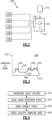
- FIG. 2 schematically illustrates an exemplary sensor system 100 including an aircraft system sensor 110, and multiple MEMS 120, 122, 124, 126, 128.
- Each of the MEMS 120, 122, 124, 126, 128 is positioned within an aircraft system, such as a gas turbine engine, and is disposed local to a corresponding component within the aircraft system.
- Each of the MEMS 120, 122, 124, 126, 128 and the system sensor 110 are connected to a controller 130.
- the controller 130 includes a MEMS module 132 configured to receive and interpret signals from each of the MEMS 120, 122, 124, 126, 128.
- the MEMS module 132 can be a software module, stored in a memory of the controller 130, or a hardware portion of the controller 130, depending on the needs and environment of the specific aircraft system, and the controller 130.
- the data acquisition module 134 acquires sensor data from the aircraft system sensor 110 and provides the acquired data to a remainder of the controller 130 systems.
- the data acquisition module 134 controls a data acquisition rate of the data from the aircraft system sensor 110, and operates at a default base data acquisition rate.
- MEMS module 132 Stored within the MEMS module 132, or the data acquisition module 134, is a set of data acquisition rates, with at least one data acquisition rate corresponding to each MEMS 120, 122, 124, 126, 128.
- Each of the data acquisition rates compensates for the structural response modes of the components to which the corresponding MEMS 120, 122, 124, 126, 128 is local, and allows for a sufficient data acquisition rate from the aircraft system sensor 110 when the corresponding MEMS 120, 122, 124, 126, 128 is triggered.
- multiple MEMS 120, 122, 124, 126, 128 can correspond to the same data acquisition rate.
- multiple MEMS 120, 122, 124, 126, 128 can be triggered simultaneously, either due to a single event triggering multiple MEMS 120, 122, 124, 126, 128, or due to independent events occurring simultaneously.
- the controller 130 causes the data acquisition module 134 to adjust the data acquisition rate to be the highest data acquisition rate corresponding to one of the triggered MEMS 120, 122, 124, 126, 128 while keeping track of all triggered MEMS 120, 122, 124, 126, 128.
- the controller 130 ensures that the data is acquired at a sufficient rate to compensate for the structural vibratory mode of each of the components to which the triggered MEMS 120, 122, 124, 126, 128 is local.
- Figure 3 illustrates a chart 200 of vibrations at an exemplary MEMS 120, 122, 124, 126, 128.
- the chart 200 includes axis 210, 212 corresponding to vibration of a component to which the exemplary MEMS is local (axis 210) and corresponding to time (axis 212).
- the vibration of the component with respect to time is illustrated via a line 230.
- the signal causes the controller to increase the data acquisition rate for a system sensor to the data acquisition rate corresponding to the triggered MEMS for a predefined time window 240.
- the predefined time window 240 for every MEMS in a given system can be identical.
- the predefined time window can be unique to each MEMS, and can be selected based on an expected event type at the component corresponding to the MEMS.
- the MEMS can continuously trigger while the threshold is exceeded, and the data acquisition rate is increased for a duration equal to the predefined window plus the length that the threshold is exceeded.
- Figure 4 illustrates a method for operating the system 100 of Figure 2 .
- an initial triggering event occurs local to an engine component at a "Triggering Event Occurs" step 310.
- a MEMS local to the engine component registers the event in a "Local MEMS Registers Event” step 320.
- the local MEMS responds to the event by transmitting a signal to a controller, such as a FADEC, in a "MEMS Signals FADEC” step 330.
- the signal is, in some examples, a simple indication that the MEMS originating the signal registered an event. In other examples, additional data such as a magnitude of the event can be transmitted as well.
- the controller adjusts a data acquisition rate (sampling rate) of a corresponding system sensor that senses a parameter of the engine system in a "FADEC Adjusts Sampling Rate” step 340.
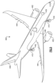
- Figure 5 illustrates an exemplary aircraft 400 including MEMS 410 disposed at additional sensitive systems outside of the gas turbine engines 402.
- MEMS 410 is connected to a corresponding controller 420, and the corresponding controller 420 is configured to increase a sampling rate of a corresponding sensor 430 using a similar process to the process described above with regards to the gas turbine engine.
- the system and process of Figures 1-4 can be expanded to additional systems and structures within the aircraft 400.
- the additional structures can include landing gears 442, wing ailerons 444, tail systems 446, wing joints 448, and the like.
- vibrational triggers and a vibrational system sensor one of skill in the art will appreciate that the system described herein can be utilized in conjunction with any other engine or system parameter sensor and is not limited to vibrational sensors.
Landscapes
- Engineering & Computer Science (AREA)
- Computer Networks & Wireless Communication (AREA)
- Signal Processing (AREA)
- Chemical & Material Sciences (AREA)
- Combustion & Propulsion (AREA)
- General Engineering & Computer Science (AREA)
- Mechanical Engineering (AREA)
- General Physics & Mathematics (AREA)
- Physics & Mathematics (AREA)
- Medical Informatics (AREA)
- General Health & Medical Sciences (AREA)
- Computing Systems (AREA)
- Health & Medical Sciences (AREA)
- Measurement Of Mechanical Vibrations Or Ultrasonic Waves (AREA)
- Micromachines (AREA)
- Testing Of Engines (AREA)
Description
- The present disclosure relates generally to aircraft sensor data acquisition, and more specifically to a system and method for actively controlling a data acquisition rate of an aircraft system sensor.
- Gas turbine engines, such as those utilized in commercial and military aircraft, include a compressor section that compresses air, a combustor section in which the compressed air is mixed with a fuel and ignited, and a turbine section across which the resultant combustion products are expanded. The expansion of the combustion products drives the turbine section to rotate. As the turbine section is connected to the compressor section via a shaft, the rotation of the turbine section further drives the compressor section to rotate. In some examples, a fan is also connected to the shaft and is driven to rotate via rotation of the turbine as well.
- During operation of the gas turbine engine, it can be desirable for an engine controller such as a full authority digital engine controller (FADEC) to monitor one or more parameters of the engine operation. The parameters can be monitored using sensors configured to detect the parameters. The data from the sensors is read at an acquisition rate (alternately referred to as a sampling rate). In some instances, such as when certain vibrational events occur, it can be desirable to read data from the sensor more frequently than the base data acquisition rate.
- A prior art aircraft sensor system and method for operating the same having the features of the preamble to claims 1 and 10 is disclosed in
US 2016/178464 . A prior art wireless engine monitoring system is also disclosed inUS 9,816,897 - According to a first aspect of the invention, there is disclosed an aircraft sensor system that includes a first sensor configured to detect a parameter of an aircraft system, a first micro electro-mechanical-system (MEMS) disposed local to a first component within the aircraft system, the first MEMS being communicatively connected to a controller, and being configured to trigger in response to a corresponding parameter exceeding a threshold, and the controller being connected to an output of the first sensor and including a non-transitory memory storing instructions configured to cause the controller to increase a sampling rate of the first sensor to a sampling rate corresponding to the first component for at least a predetermined length of time in response to the first MEMS being triggered.
- In a preferred embodiment of the above described aircraft sensor system the first sensor is a vibration sensor.
- In a preferred embodiment of any of the above described aircraft sensor systems the first sensor is disposed on a gas turbine engine housing and is configured to sense a parameter of a gas turbine engine.
- Another preferred embodiment of any of the above described aircraft sensor systems further includes a plurality of MEMS including the first MEMS, with each MEMS in the plurality of MEMS being local to a distinct component from each other MEMS in the plurality of MEMS.
- In another preferred embodiment of any of the above described aircraft sensor systems each MEMS in the plurality of MEMS is connected to the controller and is configured to trigger in response to a corresponding parameter of the component to which the MEMS is local to exceeding a threshold.
- In another preferred embodiment of any of the above described aircraft sensor systems the controller is configured to increase the sampling rate of the first sensor to a sampling rate corresponding to each MEMS in the plurality of MEMS for at least a predetermined length of time in response to the corresponding MEMS being triggered.
- In another preferred embodiment of any of the above described aircraft sensor systems the sampling rate corresponding to each MEMS is distinct from each the sampling rate corresponding to each other MEMS in the plurality of MEMS.
- In another preferred embodiment of any of the above described aircraft sensor systems the sampling rate corresponding to at least two MEMS in the plurality of MEMS is identical.
- In another preferred embodiment of any of the above described aircraft sensor systems each MEMS in the plurality of MEMS has a length in its longest dimension ranging from 20 micrometers to 1 millimeter.
- In another preferred embodiment of any of the above described aircraft sensor systems the predefined length of time has a length in the range of 100-400 ms.
- According to a second aspect of the invention there is disclosed a method for operating an aircraft sensor system that includes a controller receiving a first signal from a first micro electro-mechanical-system (MEMS) disposed local to a first component, wherein the first signal indicates that a first event has occurred, and the controller increasing a sampling rate of a system sensor from a first sampling rate to a second sampling rate for at least predefined time period in response to receiving the signal.
- In another preferred embodiment of the above described method for operating an aircraft sensor system the second sampling rate is at least sufficient to compensate for a structural vibratory mode of the first component.
- In another preferred embodiment of any of the above described methods for operating an aircraft sensor system the controller receives a second signal from a second micro electro-mechanical-system (MEMS) disposed local to a second component simultaneous with the first signal, wherein the second signal indicates that a second event has occurred, and the controller increasing the sampling rate of the system sensor from the first sampling rate to a higher of the second sampling rate and a third sampling rate, each of the second sampling rate and the third sampling rate corresponding to one of the first and second component.
- In another preferred embodiment of any of the above described methods for operating an aircraft sensor system the predefined time period begins upon receipt of the first signal.
- In another preferred embodiment of any of the above described methods for operating an aircraft sensor system the predefined time period begins when the first signal ceases being received.
- In another preferred embodiment of any of the above described methods for operating an aircraft sensor system the first event is a vibration at the first component exceeding a predetermined threshold.
- These and other features of the present invention can be best understood from the following specification and drawings, the following of which is a brief description.
-
-
Figure 1 illustrates a schematic view of an exemplary engine. -
Figure 2 schematically illustrates a notional system configuration for a data acquisition management system. -
Figure 3 schematically illustrates a data acquisition rate chart during an exemplary aircraft operation. -
Figure 4 illustrates an exemplary method of operating a data acquisition management system. -
Figure 5 schematically illustrates an aircraft including a data acquisition management system expanded beyond an aircraft engine. -
Figure 1 schematically illustrates agas turbine engine 20. Thegas turbine engine 20 is disclosed herein as a two-spool turbofan that generally incorporates afan section 22, acompressor section 24, acombustor section 26 and aturbine section 28. Thefan section 22 drives air along a bypass flow path B in a bypass duct defined within anacelle 15, and also drives air along a core flow path C for compression and communication into thecombustor section 26 then expansion through theturbine section 28. Although depicted as a two-spool turbofan gas turbine engine in the disclosed non-limiting embodiment, it should be understood that the concepts described herein are not limited to use with two-spool turbofans as the teachings may be applied to other types of turbine engines including three-spool architectures. - The
exemplary engine 20 generally includes alow speed spool 30 and ahigh speed spool 32 mounted for rotation about an engine central longitudinal axis A relative to an enginestatic structure 36 viaseveral bearing systems 38. It should be understood thatvarious bearing systems 38 at various locations may alternatively or additionally be provided, and the location ofbearing systems 38 may be varied as appropriate to the application. - The
low speed spool 30 generally includes aninner shaft 40 that interconnects afan 42, a first (or low)pressure compressor 44 and a first (or low)pressure turbine 46. Theinner shaft 40 is connected to thefan 42 through a speed change mechanism, which in exemplarygas turbine engine 20 is illustrated as a gearedarchitecture 48 to drive thefan 42 at a lower speed than thelow speed spool 30. Thehigh speed spool 32 includes anouter shaft 50 that interconnects a second (or high)pressure compressor 52 and a second (or high)pressure turbine 54. Acombustor 56 is arranged inexemplary gas turbine 20 between thehigh pressure compressor 52 and thehigh pressure turbine 54. Amid-turbine frame 57 of the enginestatic structure 36 is arranged generally between thehigh pressure turbine 54 and thelow pressure turbine 46. Themid-turbine frame 57 further supports bearingsystems 38 in theturbine section 28. Theinner shaft 40 and theouter shaft 50 are concentric and rotate viabearing systems 38 about the engine central longitudinal axis A which is collinear with their longitudinal axes. - The core airflow is compressed by the
low pressure compressor 44 then thehigh pressure compressor 52, mixed and burned with fuel in thecombustor 56, then expanded over thehigh pressure turbine 54 andlow pressure turbine 46. Themid-turbine frame 57 includesairfoils 59 which are in the core airflow path C. Theturbines low speed spool 30 andhigh speed spool 32 in response to the expansion. It will be appreciated that each of the positions of thefan section 22,compressor section 24,combustor section 26,turbine section 28, and fandrive gear system 48 may be varied. For example,gear system 48 may be located aft ofcombustor section 26 or even aft ofturbine section 28, andfan section 22 may be positioned forward or aft of the location ofgear system 48. - The
engine 20 in one example is a high-bypass geared aircraft engine. In a further example, theengine 20 bypass ratio is greater than about six (6), with an example embodiment being greater than about ten (10), the gearedarchitecture 48 is an epicyclic gear train, such as a planetary gear system or other gear system, with a gear reduction ratio of greater than about 2.3 and thelow pressure turbine 46 has a pressure ratio that is greater than about five. In one disclosed embodiment, theengine 20 bypass ratio is greater than about ten (10:1), the fan diameter is significantly larger than that of thelow pressure compressor 44, and thelow pressure turbine 46 has a pressure ratio that is greater than about five 5:1.Low pressure turbine 46 pressure ratio is pressure measured prior to inlet oflow pressure turbine 46 as related to the pressure at the outlet of thelow pressure turbine 46 prior to an exhaust nozzle. The gearedarchitecture 48 may be an epicycle gear train, such as a planetary gear system or other gear system, with a gear reduction ratio of greater than about 2.3:1. It should be understood, however, that the above parameters are only exemplary of one embodiment of a geared architecture engine and that the present invention is applicable to other gas turbine engines including direct drive turbofans. - A significant amount of thrust is provided by the bypass flow B due to the high bypass ratio. The
fan section 22 of theengine 20 is designed for a particular flight condition -- typically cruise at about 0.8 Mach and about 35,000 feet (10,668 meters). The flight condition of 0.8 Mach and 35,000 ft (10,668 meters), with the engine at its best fuel consumption - also known as "bucket cruise Thrust Specific Fuel Consumption ('TSFC')" - is the industry standard parameter of lbm of fuel being burned divided by lbf of thrust the engine produces at that minimum point. "Low fan pressure ratio" is the pressure ratio across the fan blade alone, without a Fan Exit Guide Vane ("FEGV") system. The low fan pressure ratio as disclosed herein according to one non-limiting embodiment is less than about 1.45. "Low corrected fan tip speed" is the actual fan tip speed in ft/sec divided by an industry standard temperature correction of [(Tram °R) / (518.7 °R)]0.5 with °R=9/5∗K. - The "Low corrected fan tip speed" as disclosed herein according to one non-limiting embodiment is less than about 1150 ft / second (350.5 meters/second).
- The exemplary
gas turbine engine 20 includes avibrational sensor 90 positioned in or on the exterior casing of theengine 20. Thevibrational sensor 90 is configured to detect an overall magnitude of vibrations within theengine 20 at any given time. Due to its position, the isolation ability of thevibration sensor 90 is limited to distinct shafts and has limited capability to distinguish between related components. Thevibrational sensor 90 is connected to acontroller 92, such as a full authority digital engine controller (FADEC). In alternative examples, thecontroller 92 can be a general aircraft controller, a dedicated sensor controller, or any other type of controller configured to receive and interpret signals from thevibrational sensor 90, and from one or more micro-electromechanical-systems (MEMS). - Positioned local to each bearing
system 38 is a micro-electro-mechanical-system (MEMS) 94. As used herein a component, such as theMEMS 94, is "local to" a system when the component is either positioned on or in the component to which it is local, or is in a position where vibrational forces on the component are dominated by the vibrational forces on the system to which the component is local. Each of theMEMS 94 is connected to thecontroller 92 either via a wireless connection, or a direct wired connection depending on the particular characteristics of thespecific engine 20. While illustrated as positioned local to each of the bearingsystems 38 of theengine 20, it is appreciated that theMEMS 94 can be positioned local to any number of different components including, but not limited to, an accessory gearbox, a fuel pump, an oil pump, airframe components, or any other line replaceable component. - As used herein
MEMS 94 refer to microscopic, or similarly small, electromechanical devices configured to detect the occurrence of an event and transmit a signal when the occurrence is detected. In some examples, theMEMS 94 are made up of components ranging from 1 to 100 micrometers in size and theMEMS 94 will typically have an length in its longest dimension ranging from 20 micrometers to 1 millimeter. In some examples theMEMS 94 include a processor and micro sensors configured to sense and interpret the immediately surrounding environment. - Each of the
MEMS 94 is configured to trigger when vibrational forces on theMEMS 94 exceed a predetermined threshold. When triggered, theMEMS 94 provides a signal to thecontroller 92. Thecontroller 92, in turn, increases a data acquisition rate of thevibrational sensor 90, such that the increased data acquisition rate compensates for a structural response mode of the particular system that theMEMS 94 is local to. The data acquisition rate remains adjusted for a predetermined duration. In some examples the predetermined duration is at least the length of an expected vibrational event. In further examples, the predetermined duration can be within the range of 100-400 ms. Once the predetermined duration has elapsed, the data acquisition rate is decreased to the original rate, and normal data collection from thesensor 90 is resumed. - While
Figure 1 illustrates asingle system sensor 90, it is appreciated thatmultiple system sensors 90 can be connected and operate in the same manner. In such an example, each of theMEMS 94 each correspond to one ormore system sensor 90. - With continued reference to
Figure 1 ,Figure 2 schematically illustrates anexemplary sensor system 100 including anaircraft system sensor 110, andmultiple MEMS MEMS MEMS system sensor 110 are connected to acontroller 130. Thecontroller 130 includes aMEMS module 132 configured to receive and interpret signals from each of theMEMS MEMS module 132 can be a software module, stored in a memory of thecontroller 130, or a hardware portion of thecontroller 130, depending on the needs and environment of the specific aircraft system, and thecontroller 130. - Also included within the
controller 130 is adata acquisition module 134. Thedata acquisition module 134 acquires sensor data from theaircraft system sensor 110 and provides the acquired data to a remainder of thecontroller 130 systems. Thedata acquisition module 134 controls a data acquisition rate of the data from theaircraft system sensor 110, and operates at a default base data acquisition rate. - Stored within the
MEMS module 132, or thedata acquisition module 134, is a set of data acquisition rates, with at least one data acquisition rate corresponding to eachMEMS corresponding MEMS aircraft system sensor 110 when the correspondingMEMS multiple MEMS - In some cases,
multiple MEMS multiple MEMS multiple MEMS controller 130 causes thedata acquisition module 134 to adjust the data acquisition rate to be the highest data acquisition rate corresponding to one of the triggeredMEMS MEMS controller 130 ensures that the data is acquired at a sufficient rate to compensate for the structural vibratory mode of each of the components to which the triggeredMEMS - With continued reference to
Figures 1 and2, Figure 3 illustrates achart 200 of vibrations at anexemplary MEMS chart 200 includesaxis line 230. Each time the vibrations exceed athreshold 232, the MEMS is triggered and a signal is sent to the controller from the MEMS. The signal causes the controller to increase the data acquisition rate for a system sensor to the data acquisition rate corresponding to the triggered MEMS for apredefined time window 240. In some examples, thepredefined time window 240 for every MEMS in a given system can be identical. In alternative examples, the predefined time window can be unique to each MEMS, and can be selected based on an expected event type at the component corresponding to the MEMS. In yet further examples, the MEMS can continuously trigger while the threshold is exceeded, and the data acquisition rate is increased for a duration equal to the predefined window plus the length that the threshold is exceeded. - With continued reference to
Figures 1-3 ,Figure 4 illustrates a method for operating thesystem 100 ofFigure 2 . During operation of the aircraft, an initial triggering event occurs local to an engine component at a "Triggering Event Occurs"step 310. In response to the occurrence of the triggering event, a MEMS local to the engine component registers the event in a "Local MEMS Registers Event"step 320. The local MEMS responds to the event by transmitting a signal to a controller, such as a FADEC, in a "MEMS Signals FADEC"step 330. The signal is, in some examples, a simple indication that the MEMS originating the signal registered an event. In other examples, additional data such as a magnitude of the event can be transmitted as well. When the controller receives the signal, the controller adjusts a data acquisition rate (sampling rate) of a corresponding system sensor that senses a parameter of the engine system in a "FADEC Adjusts Sampling Rate"step 340. - With continued reference to
Figures 1-4 ,Figure 5 illustrates anexemplary aircraft 400 includingMEMS 410 disposed at additional sensitive systems outside of thegas turbine engines 402. Each of theMEMS 410 is connected to acorresponding controller 420, and thecorresponding controller 420 is configured to increase a sampling rate of acorresponding sensor 430 using a similar process to the process described above with regards to the gas turbine engine. In this way, the system and process ofFigures 1-4 can be expanded to additional systems and structures within theaircraft 400. By way of example, the additional structures can includelanding gears 442,wing ailerons 444,tail systems 446, wing joints 448, and the like. Further, while described above with specific relationship to vibrational triggers and a vibrational system sensor, one of skill in the art will appreciate that the system described herein can be utilized in conjunction with any other engine or system parameter sensor and is not limited to vibrational sensors. - Although an embodiment of this invention has been disclosed, a worker of ordinary skill in this art would recognize that certain modifications would come within the scope of this invention. For that reason, the following claims should be studied to determine the true scope and content of this invention.
Claims (15)
- An aircraft sensor system (100) comprising:a first sensor (90; 110; 430) configured to detect a parameter of an aircraft system;a first micro electro-mechanical-system (MEMS) (120, 122, 124, 126, 128; 410) disposed local to a first component within the aircraft system, the first MEMS (120, 122, 124, 126, 128; 410) being communicatively connected to a controller (92; 130; 420); and characterised bythe controller (92; 130; 420) being configured to trigger in response to a corresponding parameter exceeding a threshold (232); and bythe controller (92; 130; 420) being connected to an output of the first sensor (90; 110; 430) and including a non-transitory memory storing instructions configured to cause the controller (92; 130; 420) to increase a sampling rate of the first sensor (90; 110; 430) to a sampling rate corresponding to the first component for at least a predetermined length of time, for example having a length in the range of 100-400 ms, in response to the first MEMS (120, 122, 124, 126, 128; 410) being triggered.
- The aircraft sensor system of claim 1, wherein the first sensor (90; 110; 430) is a vibration sensor.
- The aircraft sensor system of claim 1 or 2, wherein the first sensor (90; 110) is disposed on a gas turbine engine housing and is configured to sense a parameter of a gas turbine engine (20; 402).
- The aircraft sensor system of claim 1, 2 or 3, further comprising a plurality of MEMS (120, 122, 124, 126, 128; 410) including the first MEMS, with each MEMS in the plurality of MEMS (120, 122, 124, 126, 128; 410) being local to a distinct component from each other MEMS in the plurality of MEMS (120, 122, 124, 126, 128; 410).
- The aircraft sensor system of claim 4, wherein each MEMS in the plurality of MEMS (120, 122, 124, 126, 128; 410) is connected to the controller (92; 130; 420) and is configured to trigger in response to a corresponding parameter of the component to which the MEMS (120, 122, 124, 126, 128; 410) is local to exceeding a threshold (232).
- The aircraft sensor system of claim 5, wherein the controller (92; 130; 420) is configured to increase the sampling rate of the first sensor (90; 110; 430) to a sampling rate corresponding to each MEMS in the plurality of MEMS (120, 122, 124, 126, 128; 410) for at least a predetermined length of time in response to the corresponding MEMS (120, 122, 124, 126, 128; 410) being triggered.
- The aircraft sensor system of claim 6, wherein the sampling rate corresponding to each MEMS (120, 122, 124, 126, 128; 410) is distinct from the sampling rate corresponding to each other MEMS in the plurality of MEMS (120, 122, 124, 126, 128; 410).
- The aircraft sensor system of claim 6, wherein the sampling rate corresponding to at least two MEMS in the plurality of MEMS (120, 122, 124, 126, 128; 410) is identical.
- The aircraft sensor system of any of claims 4 to 8, wherein each MEMS in the plurality of MEMS (120, 122, 124, 126, 128; 410) has a length in its longest dimension ranging from 20 micrometers to 1 millimeter.
- A method for operating an aircraft sensor system (100) comprising:a controller (92; 130; 420) receiving a first signal from a first micro electro-mechanical-system (MEMS) (120, 122, 124, 126, 128; 410) disposed local to a first component, wherein the first signal indicates that a first event has occurred; and characterised bythe controller (92; 130; 420) increasing a sampling rate of a system sensor (90; 110; 430) from a first sampling rate to a second sampling rate for at least predefined time period in response to receiving the signal.
- The method of claim 10, wherein the first event is a vibration at the first component exceeding a predetermined threshold (232).
- The method of claim 10 or 11, wherein the second sampling rate is at least sufficient to compensate for a structural vibratory mode of the first component.
- The method of claim 10, 11 or 12, wherein the controller (92; 130; 420) receives a second signal from a second micro electro-mechanical-system (MEMS) (120, 122, 124, 126, 128; 410) disposed local to a second component simultaneous with the first signal, wherein the second signal indicates that a second event has occurred, and the controller (92; 130; 420) increasing the sampling rate of the system sensor (90; 110; 430) from the first sampling rate to a higher of the second sampling rate and a third sampling rate, each of the second sampling rate and the third sampling rate corresponding to one of the first and second component.
- The method of any of claims 10 to 13, wherein the predefined time period begins upon receipt of the first signal.
- The method of any of claims 10 to 14, wherein the predefined time period begins when the first signal ceases being received.
Priority Applications (1)
| Application Number | Priority Date | Filing Date | Title |
|---|---|---|---|
| EP23165605.9A EP4219911B1 (en) | 2018-10-30 | 2019-10-29 | System for active data acquisition management in a gas turbine engine |
Applications Claiming Priority (1)
| Application Number | Priority Date | Filing Date | Title |
|---|---|---|---|
| US16/174,396 US10958542B2 (en) | 2018-10-30 | 2018-10-30 | System for active data acquisition management in a gas turbine engine |
Related Child Applications (1)
| Application Number | Title | Priority Date | Filing Date |
|---|---|---|---|
| EP23165605.9A Division EP4219911B1 (en) | 2018-10-30 | 2019-10-29 | System for active data acquisition management in a gas turbine engine |
Publications (2)
| Publication Number | Publication Date |
|---|---|
| EP3690194A1 EP3690194A1 (en) | 2020-08-05 |
| EP3690194B1 true EP3690194B1 (en) | 2023-04-19 |
Family
ID=68387226
Family Applications (2)
| Application Number | Title | Priority Date | Filing Date |
|---|---|---|---|
| EP19205840.2A Active EP3690194B1 (en) | 2018-10-30 | 2019-10-29 | System for active data acquisition management in a gas turbine engine |
| EP23165605.9A Active EP4219911B1 (en) | 2018-10-30 | 2019-10-29 | System for active data acquisition management in a gas turbine engine |
Family Applications After (1)
| Application Number | Title | Priority Date | Filing Date |
|---|---|---|---|
| EP23165605.9A Active EP4219911B1 (en) | 2018-10-30 | 2019-10-29 | System for active data acquisition management in a gas turbine engine |
Country Status (2)
| Country | Link |
|---|---|
| US (1) | US10958542B2 (en) |
| EP (2) | EP3690194B1 (en) |
Families Citing this family (1)
| Publication number | Priority date | Publication date | Assignee | Title |
|---|---|---|---|---|
| CN121347156B (en) * | 2025-12-17 | 2026-03-24 | 和和能源(北京)有限公司 | MEMS sensor-based premixed flame combustion process testing system |
Family Cites Families (8)
| Publication number | Priority date | Publication date | Assignee | Title |
|---|---|---|---|---|
| US9576404B2 (en) * | 2004-09-16 | 2017-02-21 | Harris Corporation | System and method of transmitting data from an aircraft |
| US8239160B2 (en) | 2008-03-21 | 2012-08-07 | Analog Devices, Inc. | Activity detection in MEMS accelerometers |
| US9140590B2 (en) | 2011-02-09 | 2015-09-22 | Texas Instruments Incorporated | System and method of power-saving in MEMS sensor applications |
| FR2974900B1 (en) * | 2011-05-02 | 2013-05-17 | Aircelle Sa | MONITORING ASSEMBLY AND METHOD FOR DETECTING STRUCTURAL DEFECTS MAY APPEAR IN AN AIRCRAFT NACELLE |
| US9816897B2 (en) | 2012-06-06 | 2017-11-14 | Harris Corporation | Wireless engine monitoring system and associated engine wireless sensor network |
| US9026279B2 (en) * | 2012-06-06 | 2015-05-05 | Harris Corporation | Wireless engine monitoring system and configurable wireless engine sensors |
| US9293033B2 (en) * | 2013-07-16 | 2016-03-22 | The Boeing Company | Wireless fuel sensor system |
| US20160178464A1 (en) | 2014-12-19 | 2016-06-23 | Rolls-Royce Corporation | Torque sensor monitoring for gas turbine engine |
-
2018
- 2018-10-30 US US16/174,396 patent/US10958542B2/en active Active
-
2019
- 2019-10-29 EP EP19205840.2A patent/EP3690194B1/en active Active
- 2019-10-29 EP EP23165605.9A patent/EP4219911B1/en active Active
Also Published As
| Publication number | Publication date |
|---|---|
| US10958542B2 (en) | 2021-03-23 |
| EP4219911A1 (en) | 2023-08-02 |
| EP3690194A1 (en) | 2020-08-05 |
| EP4219911B1 (en) | 2026-04-08 |
| US20200136936A1 (en) | 2020-04-30 |
Similar Documents
| Publication | Publication Date | Title |
|---|---|---|
| EP3039251B1 (en) | Gas turbine engine with fan clearance control | |
| EP2809921B1 (en) | Gas turbine engine with compressor inlet guide vane positioned for starting | |
| EP3808964B1 (en) | Geared turbofan with non-epicyclic gear reduction system | |
| EP2809927B1 (en) | Speed sensor probe location in gas turbine engine | |
| US20160319837A1 (en) | Active flutter control of variable pitch blades | |
| EP3798427B1 (en) | Turbomachine geared architecture support assembly | |
| EP3543483B1 (en) | Windmill lubrication gear train for lubricant system in a geared gas turbine engine | |
| EP3828401B1 (en) | Gas turbine engine inlet temperature sensor configuration | |
| EP2946083B1 (en) | Turbine case adjustment using adjustable tie rods | |
| US20130199206A1 (en) | Speed sensor probe location in gas turbine engine | |
| EP3014089B1 (en) | Excessive deformation monitoring using a fan drive gear system | |
| EP3159494B1 (en) | Autonomous engine health management system | |
| EP2809924B1 (en) | Gas turbine engine with variable area fan nozzle positioned for starting | |
| EP3690194B1 (en) | System for active data acquisition management in a gas turbine engine | |
| EP3502442B1 (en) | Concentric power takeoff transmission | |
| EP2898210A1 (en) | System for decoupling drive shaft of variable area fan nozzle | |
| EP2932072B1 (en) | Fan drive gear system assembly guide | |
| EP2971675B1 (en) | Speed sensor probe location in a gas turbine engine | |
| EP3385508B1 (en) | Bellcrank assembly for gas turbine engine and corrsponding method | |
| EP3502441A1 (en) | Light-off detection system for gas turbine engines | |
| EP4102045B1 (en) | Fiber optic exit area sensing for gas turbine engine nozzles | |
| EP2894403B1 (en) | Attachment of ceramic matrix composite panel to liner |
Legal Events
| Date | Code | Title | Description |
|---|---|---|---|
| PUAI | Public reference made under article 153(3) epc to a published international application that has entered the european phase |
Free format text: ORIGINAL CODE: 0009012 |
|
| STAA | Information on the status of an ep patent application or granted ep patent |
Free format text: STATUS: THE APPLICATION HAS BEEN PUBLISHED |
|
| AK | Designated contracting states |
Kind code of ref document: A1 Designated state(s): AL AT BE BG CH CY CZ DE DK EE ES FI FR GB GR HR HU IE IS IT LI LT LU LV MC MK MT NL NO PL PT RO RS SE SI SK SM TR |
|
| AX | Request for extension of the european patent |
Extension state: BA ME |
|
| STAA | Information on the status of an ep patent application or granted ep patent |
Free format text: STATUS: REQUEST FOR EXAMINATION WAS MADE |
|
| 17P | Request for examination filed |
Effective date: 20210201 |
|
| RBV | Designated contracting states (corrected) |
Designated state(s): AL AT BE BG CH CY CZ DE DK EE ES FI FR GB GR HR HU IE IS IT LI LT LU LV MC MK MT NL NO PL PT RO RS SE SI SK SM TR |
|
| RAP1 | Party data changed (applicant data changed or rights of an application transferred) |
Owner name: RAYTHEON TECHNOLOGIES CORPORATION |
|
| GRAP | Despatch of communication of intention to grant a patent |
Free format text: ORIGINAL CODE: EPIDOSNIGR1 |
|
| STAA | Information on the status of an ep patent application or granted ep patent |
Free format text: STATUS: GRANT OF PATENT IS INTENDED |
|
| INTG | Intention to grant announced |
Effective date: 20221031 |
|
| GRAS | Grant fee paid |
Free format text: ORIGINAL CODE: EPIDOSNIGR3 |
|
| GRAA | (expected) grant |
Free format text: ORIGINAL CODE: 0009210 |
|
| STAA | Information on the status of an ep patent application or granted ep patent |
Free format text: STATUS: THE PATENT HAS BEEN GRANTED |
|
| AK | Designated contracting states |
Kind code of ref document: B1 Designated state(s): AL AT BE BG CH CY CZ DE DK EE ES FI FR GB GR HR HU IE IS IT LI LT LU LV MC MK MT NL NO PL PT RO RS SE SI SK SM TR |
|
| REG | Reference to a national code |
Ref country code: GB Ref legal event code: FG4D |
|
| REG | Reference to a national code |
Ref country code: CH Ref legal event code: EP |
|
| REG | Reference to a national code |
Ref country code: DE Ref legal event code: R096 Ref document number: 602019027673 Country of ref document: DE |
|
| REG | Reference to a national code |
Ref country code: IE Ref legal event code: FG4D |
|
| REG | Reference to a national code |
Ref country code: AT Ref legal event code: REF Ref document number: 1561315 Country of ref document: AT Kind code of ref document: T Effective date: 20230515 |
|
| P01 | Opt-out of the competence of the unified patent court (upc) registered |
Effective date: 20230521 |
|
| REG | Reference to a national code |
Ref country code: LT Ref legal event code: MG9D |
|
| REG | Reference to a national code |
Ref country code: NL Ref legal event code: MP Effective date: 20230419 |
|
| REG | Reference to a national code |
Ref country code: AT Ref legal event code: MK05 Ref document number: 1561315 Country of ref document: AT Kind code of ref document: T Effective date: 20230419 |
|
| PG25 | Lapsed in a contracting state [announced via postgrant information from national office to epo] |
Ref country code: NL Free format text: LAPSE BECAUSE OF FAILURE TO SUBMIT A TRANSLATION OF THE DESCRIPTION OR TO PAY THE FEE WITHIN THE PRESCRIBED TIME-LIMIT Effective date: 20230419 |
|
| PG25 | Lapsed in a contracting state [announced via postgrant information from national office to epo] |
Ref country code: SE Free format text: LAPSE BECAUSE OF FAILURE TO SUBMIT A TRANSLATION OF THE DESCRIPTION OR TO PAY THE FEE WITHIN THE PRESCRIBED TIME-LIMIT Effective date: 20230419 Ref country code: PT Free format text: LAPSE BECAUSE OF FAILURE TO SUBMIT A TRANSLATION OF THE DESCRIPTION OR TO PAY THE FEE WITHIN THE PRESCRIBED TIME-LIMIT Effective date: 20230821 Ref country code: NO Free format text: LAPSE BECAUSE OF FAILURE TO SUBMIT A TRANSLATION OF THE DESCRIPTION OR TO PAY THE FEE WITHIN THE PRESCRIBED TIME-LIMIT Effective date: 20230719 Ref country code: ES Free format text: LAPSE BECAUSE OF FAILURE TO SUBMIT A TRANSLATION OF THE DESCRIPTION OR TO PAY THE FEE WITHIN THE PRESCRIBED TIME-LIMIT Effective date: 20230419 Ref country code: AT Free format text: LAPSE BECAUSE OF FAILURE TO SUBMIT A TRANSLATION OF THE DESCRIPTION OR TO PAY THE FEE WITHIN THE PRESCRIBED TIME-LIMIT Effective date: 20230419 |
|
| RAP4 | Party data changed (patent owner data changed or rights of a patent transferred) |
Owner name: RTX CORPORATION |
|
| PG25 | Lapsed in a contracting state [announced via postgrant information from national office to epo] |
Ref country code: RS Free format text: LAPSE BECAUSE OF FAILURE TO SUBMIT A TRANSLATION OF THE DESCRIPTION OR TO PAY THE FEE WITHIN THE PRESCRIBED TIME-LIMIT Effective date: 20230419 Ref country code: PL Free format text: LAPSE BECAUSE OF FAILURE TO SUBMIT A TRANSLATION OF THE DESCRIPTION OR TO PAY THE FEE WITHIN THE PRESCRIBED TIME-LIMIT Effective date: 20230419 Ref country code: LV Free format text: LAPSE BECAUSE OF FAILURE TO SUBMIT A TRANSLATION OF THE DESCRIPTION OR TO PAY THE FEE WITHIN THE PRESCRIBED TIME-LIMIT Effective date: 20230419 Ref country code: LT Free format text: LAPSE BECAUSE OF FAILURE TO SUBMIT A TRANSLATION OF THE DESCRIPTION OR TO PAY THE FEE WITHIN THE PRESCRIBED TIME-LIMIT Effective date: 20230419 Ref country code: IS Free format text: LAPSE BECAUSE OF FAILURE TO SUBMIT A TRANSLATION OF THE DESCRIPTION OR TO PAY THE FEE WITHIN THE PRESCRIBED TIME-LIMIT Effective date: 20230819 Ref country code: HR Free format text: LAPSE BECAUSE OF FAILURE TO SUBMIT A TRANSLATION OF THE DESCRIPTION OR TO PAY THE FEE WITHIN THE PRESCRIBED TIME-LIMIT Effective date: 20230419 Ref country code: GR Free format text: LAPSE BECAUSE OF FAILURE TO SUBMIT A TRANSLATION OF THE DESCRIPTION OR TO PAY THE FEE WITHIN THE PRESCRIBED TIME-LIMIT Effective date: 20230720 Ref country code: AL Free format text: LAPSE BECAUSE OF FAILURE TO SUBMIT A TRANSLATION OF THE DESCRIPTION OR TO PAY THE FEE WITHIN THE PRESCRIBED TIME-LIMIT Effective date: 20230419 |
|
| PG25 | Lapsed in a contracting state [announced via postgrant information from national office to epo] |
Ref country code: FI Free format text: LAPSE BECAUSE OF FAILURE TO SUBMIT A TRANSLATION OF THE DESCRIPTION OR TO PAY THE FEE WITHIN THE PRESCRIBED TIME-LIMIT Effective date: 20230419 |
|
| PG25 | Lapsed in a contracting state [announced via postgrant information from national office to epo] |
Ref country code: SK Free format text: LAPSE BECAUSE OF FAILURE TO SUBMIT A TRANSLATION OF THE DESCRIPTION OR TO PAY THE FEE WITHIN THE PRESCRIBED TIME-LIMIT Effective date: 20230419 |
|
| REG | Reference to a national code |
Ref country code: DE Ref legal event code: R097 Ref document number: 602019027673 Country of ref document: DE |
|
| PG25 | Lapsed in a contracting state [announced via postgrant information from national office to epo] |
Ref country code: SM Free format text: LAPSE BECAUSE OF FAILURE TO SUBMIT A TRANSLATION OF THE DESCRIPTION OR TO PAY THE FEE WITHIN THE PRESCRIBED TIME-LIMIT Effective date: 20230419 Ref country code: SK Free format text: LAPSE BECAUSE OF FAILURE TO SUBMIT A TRANSLATION OF THE DESCRIPTION OR TO PAY THE FEE WITHIN THE PRESCRIBED TIME-LIMIT Effective date: 20230419 Ref country code: RO Free format text: LAPSE BECAUSE OF FAILURE TO SUBMIT A TRANSLATION OF THE DESCRIPTION OR TO PAY THE FEE WITHIN THE PRESCRIBED TIME-LIMIT Effective date: 20230419 Ref country code: EE Free format text: LAPSE BECAUSE OF FAILURE TO SUBMIT A TRANSLATION OF THE DESCRIPTION OR TO PAY THE FEE WITHIN THE PRESCRIBED TIME-LIMIT Effective date: 20230419 Ref country code: DK Free format text: LAPSE BECAUSE OF FAILURE TO SUBMIT A TRANSLATION OF THE DESCRIPTION OR TO PAY THE FEE WITHIN THE PRESCRIBED TIME-LIMIT Effective date: 20230419 Ref country code: CZ Free format text: LAPSE BECAUSE OF FAILURE TO SUBMIT A TRANSLATION OF THE DESCRIPTION OR TO PAY THE FEE WITHIN THE PRESCRIBED TIME-LIMIT Effective date: 20230419 |
|
| PLBE | No opposition filed within time limit |
Free format text: ORIGINAL CODE: 0009261 |
|
| STAA | Information on the status of an ep patent application or granted ep patent |
Free format text: STATUS: NO OPPOSITION FILED WITHIN TIME LIMIT |
|
| 26N | No opposition filed |
Effective date: 20240122 |
|
| PG25 | Lapsed in a contracting state [announced via postgrant information from national office to epo] |
Ref country code: SI Free format text: LAPSE BECAUSE OF FAILURE TO SUBMIT A TRANSLATION OF THE DESCRIPTION OR TO PAY THE FEE WITHIN THE PRESCRIBED TIME-LIMIT Effective date: 20230419 |
|
| PG25 | Lapsed in a contracting state [announced via postgrant information from national office to epo] |
Ref country code: SI Free format text: LAPSE BECAUSE OF FAILURE TO SUBMIT A TRANSLATION OF THE DESCRIPTION OR TO PAY THE FEE WITHIN THE PRESCRIBED TIME-LIMIT Effective date: 20230419 Ref country code: IT Free format text: LAPSE BECAUSE OF FAILURE TO SUBMIT A TRANSLATION OF THE DESCRIPTION OR TO PAY THE FEE WITHIN THE PRESCRIBED TIME-LIMIT Effective date: 20230419 Ref country code: MC Free format text: LAPSE BECAUSE OF FAILURE TO SUBMIT A TRANSLATION OF THE DESCRIPTION OR TO PAY THE FEE WITHIN THE PRESCRIBED TIME-LIMIT Effective date: 20230419 |
|
| REG | Reference to a national code |
Ref country code: CH Ref legal event code: PL |
|
| REG | Reference to a national code |
Ref country code: BE Ref legal event code: MM Effective date: 20231031 |
|
| PG25 | Lapsed in a contracting state [announced via postgrant information from national office to epo] |
Ref country code: LU Free format text: LAPSE BECAUSE OF NON-PAYMENT OF DUE FEES Effective date: 20231029 |
|
| PG25 | Lapsed in a contracting state [announced via postgrant information from national office to epo] |
Ref country code: LU Free format text: LAPSE BECAUSE OF NON-PAYMENT OF DUE FEES Effective date: 20231029 |
|
| PG25 | Lapsed in a contracting state [announced via postgrant information from national office to epo] |
Ref country code: CH Free format text: LAPSE BECAUSE OF NON-PAYMENT OF DUE FEES Effective date: 20231031 |
|
| PG25 | Lapsed in a contracting state [announced via postgrant information from national office to epo] |
Ref country code: CH Free format text: LAPSE BECAUSE OF NON-PAYMENT OF DUE FEES Effective date: 20231031 |
|
| PG25 | Lapsed in a contracting state [announced via postgrant information from national office to epo] |
Ref country code: BE Free format text: LAPSE BECAUSE OF NON-PAYMENT OF DUE FEES Effective date: 20231031 |
|
| PG25 | Lapsed in a contracting state [announced via postgrant information from national office to epo] |
Ref country code: IE Free format text: LAPSE BECAUSE OF NON-PAYMENT OF DUE FEES Effective date: 20231029 |
|
| PG25 | Lapsed in a contracting state [announced via postgrant information from national office to epo] |
Ref country code: IE Free format text: LAPSE BECAUSE OF NON-PAYMENT OF DUE FEES Effective date: 20231029 |
|
| PG25 | Lapsed in a contracting state [announced via postgrant information from national office to epo] |
Ref country code: BG Free format text: LAPSE BECAUSE OF FAILURE TO SUBMIT A TRANSLATION OF THE DESCRIPTION OR TO PAY THE FEE WITHIN THE PRESCRIBED TIME-LIMIT Effective date: 20230419 |
|
| PG25 | Lapsed in a contracting state [announced via postgrant information from national office to epo] |
Ref country code: BG Free format text: LAPSE BECAUSE OF FAILURE TO SUBMIT A TRANSLATION OF THE DESCRIPTION OR TO PAY THE FEE WITHIN THE PRESCRIBED TIME-LIMIT Effective date: 20230419 |
|
| PG25 | Lapsed in a contracting state [announced via postgrant information from national office to epo] |
Ref country code: CY Free format text: LAPSE BECAUSE OF FAILURE TO SUBMIT A TRANSLATION OF THE DESCRIPTION OR TO PAY THE FEE WITHIN THE PRESCRIBED TIME-LIMIT; INVALID AB INITIO Effective date: 20191029 |
|
| PG25 | Lapsed in a contracting state [announced via postgrant information from national office to epo] |
Ref country code: HU Free format text: LAPSE BECAUSE OF FAILURE TO SUBMIT A TRANSLATION OF THE DESCRIPTION OR TO PAY THE FEE WITHIN THE PRESCRIBED TIME-LIMIT; INVALID AB INITIO Effective date: 20191029 |
|
| REG | Reference to a national code |
Ref country code: DE Ref legal event code: R081 Ref document number: 602019027673 Country of ref document: DE Owner name: RTX CORPORATION (N.D.GES.D. STAATES DELAWARE),, US Free format text: FORMER OWNER: RAYTHEON TECHNOLOGIES CORPORATION, FARMINGTON, CT, US |
|
| PGFP | Annual fee paid to national office [announced via postgrant information from national office to epo] |
Ref country code: GB Payment date: 20250923 Year of fee payment: 7 |
|
| PGFP | Annual fee paid to national office [announced via postgrant information from national office to epo] |
Ref country code: FR Payment date: 20250923 Year of fee payment: 7 |
|
| PG25 | Lapsed in a contracting state [announced via postgrant information from national office to epo] |
Ref country code: TR Free format text: LAPSE BECAUSE OF FAILURE TO SUBMIT A TRANSLATION OF THE DESCRIPTION OR TO PAY THE FEE WITHIN THE PRESCRIBED TIME-LIMIT Effective date: 20230419 |
|
| PGFP | Annual fee paid to national office [announced via postgrant information from national office to epo] |
Ref country code: DE Payment date: 20250923 Year of fee payment: 7 |