EP3690192A1 - Rotor hybride à tambour segmenté - Google Patents
Rotor hybride à tambour segmenté Download PDFInfo
- Publication number
- EP3690192A1 EP3690192A1 EP20150739.9A EP20150739A EP3690192A1 EP 3690192 A1 EP3690192 A1 EP 3690192A1 EP 20150739 A EP20150739 A EP 20150739A EP 3690192 A1 EP3690192 A1 EP 3690192A1
- Authority
- EP
- European Patent Office
- Prior art keywords
- segments
- rotor
- branch
- segment
- seal
- Prior art date
- Legal status (The legal status is an assumption and is not a legal conclusion. Google has not performed a legal analysis and makes no representation as to the accuracy of the status listed.)
- Granted
Links
Images



Classifications
-
- F—MECHANICAL ENGINEERING; LIGHTING; HEATING; WEAPONS; BLASTING
- F04—POSITIVE - DISPLACEMENT MACHINES FOR LIQUIDS; PUMPS FOR LIQUIDS OR ELASTIC FLUIDS
- F04D—NON-POSITIVE-DISPLACEMENT PUMPS
- F04D29/00—Details, component parts, or accessories
- F04D29/26—Rotors specially for elastic fluids
- F04D29/32—Rotors specially for elastic fluids for axial flow pumps
- F04D29/321—Rotors specially for elastic fluids for axial flow pumps for axial flow compressors
- F04D29/322—Blade mountings
-
- F—MECHANICAL ENGINEERING; LIGHTING; HEATING; WEAPONS; BLASTING
- F01—MACHINES OR ENGINES IN GENERAL; ENGINE PLANTS IN GENERAL; STEAM ENGINES
- F01D—NON-POSITIVE DISPLACEMENT MACHINES OR ENGINES, e.g. STEAM TURBINES
- F01D11/00—Preventing or minimising internal leakage of working-fluid, e.g. between stages
- F01D11/001—Preventing or minimising internal leakage of working-fluid, e.g. between stages for sealing space between stator blade and rotor
-
- F—MECHANICAL ENGINEERING; LIGHTING; HEATING; WEAPONS; BLASTING
- F01—MACHINES OR ENGINES IN GENERAL; ENGINE PLANTS IN GENERAL; STEAM ENGINES
- F01D—NON-POSITIVE DISPLACEMENT MACHINES OR ENGINES, e.g. STEAM TURBINES
- F01D5/00—Blades; Blade-carrying members; Heating, heat-insulating, cooling or antivibration means on the blades or the members
- F01D5/02—Blade-carrying members, e.g. rotors
- F01D5/06—Rotors for more than one axial stage, e.g. of drum or multiple disc type; Details thereof, e.g. shafts, shaft connections
- F01D5/066—Connecting means for joining rotor-discs or rotor-elements together, e.g. by a central bolt, by clamps
-
- F—MECHANICAL ENGINEERING; LIGHTING; HEATING; WEAPONS; BLASTING
- F01—MACHINES OR ENGINES IN GENERAL; ENGINE PLANTS IN GENERAL; STEAM ENGINES
- F01D—NON-POSITIVE DISPLACEMENT MACHINES OR ENGINES, e.g. STEAM TURBINES
- F01D25/00—Component parts, details, or accessories, not provided for in, or of interest apart from, other groups
- F01D25/005—Selecting particular materials
-
- F—MECHANICAL ENGINEERING; LIGHTING; HEATING; WEAPONS; BLASTING
- F04—POSITIVE - DISPLACEMENT MACHINES FOR LIQUIDS; PUMPS FOR LIQUIDS OR ELASTIC FLUIDS
- F04D—NON-POSITIVE-DISPLACEMENT PUMPS
- F04D29/00—Details, component parts, or accessories
- F04D29/02—Selection of particular materials
- F04D29/023—Selection of particular materials especially adapted for elastic fluid pumps
-
- F—MECHANICAL ENGINEERING; LIGHTING; HEATING; WEAPONS; BLASTING
- F04—POSITIVE - DISPLACEMENT MACHINES FOR LIQUIDS; PUMPS FOR LIQUIDS OR ELASTIC FLUIDS
- F04D—NON-POSITIVE-DISPLACEMENT PUMPS
- F04D29/00—Details, component parts, or accessories
- F04D29/08—Sealings
- F04D29/083—Sealings especially adapted for elastic fluid pumps
-
- F—MECHANICAL ENGINEERING; LIGHTING; HEATING; WEAPONS; BLASTING
- F04—POSITIVE - DISPLACEMENT MACHINES FOR LIQUIDS; PUMPS FOR LIQUIDS OR ELASTIC FLUIDS
- F04D—NON-POSITIVE-DISPLACEMENT PUMPS
- F04D29/00—Details, component parts, or accessories
- F04D29/08—Sealings
- F04D29/16—Sealings between pressure and suction sides
- F04D29/161—Sealings between pressure and suction sides especially adapted for elastic fluid pumps
- F04D29/164—Sealings between pressure and suction sides especially adapted for elastic fluid pumps of an axial flow wheel
-
- F—MECHANICAL ENGINEERING; LIGHTING; HEATING; WEAPONS; BLASTING
- F01—MACHINES OR ENGINES IN GENERAL; ENGINE PLANTS IN GENERAL; STEAM ENGINES
- F01D—NON-POSITIVE DISPLACEMENT MACHINES OR ENGINES, e.g. STEAM TURBINES
- F01D11/00—Preventing or minimising internal leakage of working-fluid, e.g. between stages
- F01D11/02—Preventing or minimising internal leakage of working-fluid, e.g. between stages by non-contact sealings, e.g. of labyrinth type
-
- F—MECHANICAL ENGINEERING; LIGHTING; HEATING; WEAPONS; BLASTING
- F01—MACHINES OR ENGINES IN GENERAL; ENGINE PLANTS IN GENERAL; STEAM ENGINES
- F01D—NON-POSITIVE DISPLACEMENT MACHINES OR ENGINES, e.g. STEAM TURBINES
- F01D11/00—Preventing or minimising internal leakage of working-fluid, e.g. between stages
- F01D11/08—Preventing or minimising internal leakage of working-fluid, e.g. between stages for sealing space between rotor blade tips and stator
- F01D11/12—Preventing or minimising internal leakage of working-fluid, e.g. between stages for sealing space between rotor blade tips and stator using a rubstrip, e.g. erodible. deformable or resiliently-biased part
- F01D11/122—Preventing or minimising internal leakage of working-fluid, e.g. between stages for sealing space between rotor blade tips and stator using a rubstrip, e.g. erodible. deformable or resiliently-biased part with erodable or abradable material
-
- F—MECHANICAL ENGINEERING; LIGHTING; HEATING; WEAPONS; BLASTING
- F01—MACHINES OR ENGINES IN GENERAL; ENGINE PLANTS IN GENERAL; STEAM ENGINES
- F01D—NON-POSITIVE DISPLACEMENT MACHINES OR ENGINES, e.g. STEAM TURBINES
- F01D11/00—Preventing or minimising internal leakage of working-fluid, e.g. between stages
- F01D11/08—Preventing or minimising internal leakage of working-fluid, e.g. between stages for sealing space between rotor blade tips and stator
- F01D11/12—Preventing or minimising internal leakage of working-fluid, e.g. between stages for sealing space between rotor blade tips and stator using a rubstrip, e.g. erodible. deformable or resiliently-biased part
- F01D11/127—Preventing or minimising internal leakage of working-fluid, e.g. between stages for sealing space between rotor blade tips and stator using a rubstrip, e.g. erodible. deformable or resiliently-biased part with a deformable or crushable structure, e.g. honeycomb
-
- F—MECHANICAL ENGINEERING; LIGHTING; HEATING; WEAPONS; BLASTING
- F05—INDEXING SCHEMES RELATING TO ENGINES OR PUMPS IN VARIOUS SUBCLASSES OF CLASSES F01-F04
- F05D—INDEXING SCHEME FOR ASPECTS RELATING TO NON-POSITIVE-DISPLACEMENT MACHINES OR ENGINES, GAS-TURBINES OR JET-PROPULSION PLANTS
- F05D2240/00—Components
- F05D2240/55—Seals
- F05D2240/56—Brush seals
-
- F—MECHANICAL ENGINEERING; LIGHTING; HEATING; WEAPONS; BLASTING
- F05—INDEXING SCHEMES RELATING TO ENGINES OR PUMPS IN VARIOUS SUBCLASSES OF CLASSES F01-F04
- F05D—INDEXING SCHEME FOR ASPECTS RELATING TO NON-POSITIVE-DISPLACEMENT MACHINES OR ENGINES, GAS-TURBINES OR JET-PROPULSION PLANTS
- F05D2240/00—Components
- F05D2240/55—Seals
- F05D2240/57—Leaf seals
-
- F—MECHANICAL ENGINEERING; LIGHTING; HEATING; WEAPONS; BLASTING
- F05—INDEXING SCHEMES RELATING TO ENGINES OR PUMPS IN VARIOUS SUBCLASSES OF CLASSES F01-F04
- F05D—INDEXING SCHEME FOR ASPECTS RELATING TO NON-POSITIVE-DISPLACEMENT MACHINES OR ENGINES, GAS-TURBINES OR JET-PROPULSION PLANTS
- F05D2300/00—Materials; Properties thereof
- F05D2300/60—Properties or characteristics given to material by treatment or manufacturing
- F05D2300/603—Composites; e.g. fibre-reinforced
-
- Y—GENERAL TAGGING OF NEW TECHNOLOGICAL DEVELOPMENTS; GENERAL TAGGING OF CROSS-SECTIONAL TECHNOLOGIES SPANNING OVER SEVERAL SECTIONS OF THE IPC; TECHNICAL SUBJECTS COVERED BY FORMER USPC CROSS-REFERENCE ART COLLECTIONS [XRACs] AND DIGESTS
- Y02—TECHNOLOGIES OR APPLICATIONS FOR MITIGATION OR ADAPTATION AGAINST CLIMATE CHANGE
- Y02T—CLIMATE CHANGE MITIGATION TECHNOLOGIES RELATED TO TRANSPORTATION
- Y02T50/00—Aeronautics or air transport
- Y02T50/60—Efficient propulsion technologies, e.g. for aircraft
Definitions
- the invention relates to the design of a turbomachine, in particular an airplane turbojet or an aircraft turboprop with a fan driven by a reduction gear.
- the invention relates in particular to a compressor rotor composed of several parts including a drum made of composite material.
- the document EP 2 818 635 A1 describes a compressor rotor for a turbomachine.
- a drum is arranged therein, supporting several annular rows of rotor blades, at least one blade of which is integral with the rotor.
- This hybrid design saves time during production and assembly as not all blades are integral with the drum.
- Weight is a detrimental aspect for a compressor rotor not only because it requires more energy to be put into rotation, thereby reducing the efficiency of the motor, but also because it will, to its extent, participate in the weight of the aircraft and therefore the fuel requirement necessary for the movement of the aircraft.
- the document EP 2 287 445 A1 describes a compressor rotor made up of segments of composite material and metal rings. The latter are provided with dovetail grooves to receive rotor blades.
- the object of the invention is to provide a rotor that is lighter and whose manufacture and assembly are more economical.
- the subject of the invention is a rotor for an axial turbomachine compressor, such as an aircraft turbojet, comprising: a plurality of segments, of substantially axisymmetric shape and made of composite material; a plurality of annular rows of rotor blades, each row of blades being supported by a respective ring, metallic and interposed axially between two segments of the plurality of segments, remarkable in that each ring has a section with an axial branch overlapping axially partially the two segments, the rings being connected in pairs only by means of one of the segments.
- a drum is thus formed by the succession, along an axis, of segments and rings which overlap only partially and which form a mechanically resistant assembly. Disassembling one of the elements (segment or crown) breaks the drum.
- the invention also relates to a turbomachine compressor comprising a rotor according to one of the embodiments described above and at least one row of stator vanes arranged axially between two annular rows of successive rotor vanes, the stator vanes. being supported by an internal ferrule axially overlapping a segment, and a seal being disposed between the internal ferrule and the segment.
- an axial turbomachine compressor such as an aircraft turbojet, comprising: a rotor provided with a plurality of segments, of substantially axisymmetric shape and made of composite material and with a plurality of annular rows of rotor blades supported by rings arranged between two adjacent segments; at least one row of stator vanes arranged axially between two annular rows of successive rotor vanes, the stator vanes being supported by an internal shroud axially overlapping a segment; and a seal being disposed between the inner ferrule and one of the segments.
- the subject of the invention is also a method for assembling a rotor according to one of the embodiments described above, the method comprising the alternate stacking of segments and rings and the fixing of the rings to the segments.
- the subject of the invention is also a method for assembling a compressor according to one of the embodiments described above, the method comprising the fitting of an axially overlapping segment of an internal stator shell, then the placement of a crown in contact with the segment, followed by the placement of a second segment against the crown, and finally the fixing by screw or rivet of the crown to the two segments.
- each subject of the invention is also applicable to the other subjects of the invention.
- Each object of the invention can be combined with other objects, and the objects of the invention can also be combined with the embodiments of the description, which in addition can be combined with one another, according to all the possible technical combinations, unless the contrary is the case. is not explicitly mentioned.
- the hybrid design of the rotor according to the invention allows substantial gains in weight compared to a rotor having a completely metallic drum. Compared to a one-piece rotor, the manufacturing time is drastically reduced, as several elements can be manufactured in parallel before being assembled together. Also, the axial distribution of the weight of the rotor is more homogeneous.
- the terms “internal” (or “interior”) and “external” (or “exterior”) refer to a positioning with respect to the axis of rotation of an axial turbomachine.
- the axial direction corresponds to the direction along the axis of rotation of the turbomachine.
- the radial direction is perpendicular to the axis of rotation. Upstream and downstream refer to the main flow direction of the flow in the turbomachine.
- integral is understood as integral in rotation, and in particular rigidly linked.
- the term “one-piece” is equivalent to “fully integrated” and designates various elements produced in the same block of material, as opposed to “added” which means that an element is attached, after its manufacture, to another element.
- the figures show the elements schematically, in particular without all the assembly or sealing elements. The dimensions and in particular the radial thickness, are exaggerated in order to facilitate understanding of the figures.
- the figure 1 shows in a simplified manner an axial turbomachine 2.
- the turbojet 2 comprises a first compressor, low pressure 4 and a second compressor, high pressure 6, a combustion chamber 8 and one or more turbines 10.
- the mechanical power of the turbine 10 transmitted to the rotor 12 sets in motion the two compressors 4 and 6.
- the latter comprise several rows of rotor blades associated with rows of stator blades. The rotation of the rotor around its axis of rotation 14 thus makes it possible to generate an air flow and to gradually compress the latter up to the inlet of the combustion chamber 8.
- a fan 16 is coupled to the rotor 12 and generates an air flow which is divided into a primary flow 18 and a secondary flow 20 passing through an annular duct (partially shown) along the machine to then join the primary flow at the outlet. turbine.
- Reduction means such as an epicyclic reduction gear 22, can reduce the speed of rotation of the fan and / or of the low-pressure compressor relative to the associated turbine.
- the secondary flow can be accelerated so as to generate a thrust reaction necessary for the flight of an aircraft.
- the figure 2 is a sectional view of a compressor of an axial turbomachine known.
- the compressor may include a low-pressure compressor 4. Part of the fan 16 can be seen there as well as the spout 22 for separating the primary 18 and secondary 20 flows.
- the rotor 12 may include several rows of rotor blades 24.
- the low-pressure compressor 4 comprises at least one rectifier which contains an annular row of stator vanes 26. Each rectifier is associated with the fan 16 or with a row of rotor vanes 24 in order to rectify the air flow.
- the low-pressure compressor 4 comprises at least one casing 28.
- the casing 28 may have a generally circular or tubular shape. It can be an external compressor housing and can be made of composite materials.
- the casing 28 can comprise fixing flanges 30, for example annular fixing flanges 30 for fixing the separating nozzle 22 and / or for fixing to an intermediate fan casing of the turbomachine.
- the annular flanges 30 may be of composite and include attachment holes (not shown) to allow bolt attachment.
- the casing 28 can measure between 3 and 5 mm in thickness for a diameter greater than 1 meter.
- stator vanes 26 extend essentially radially from the casing 28 to internal ferrules 32.
- the rotor 12 is in one piece with three annular rows of rotor blades 24 extending radially from the rotor 12 to the vicinity of the housing 28.
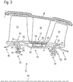
- the figure 3 illustrates in partial section part of a rotor 12 according to the invention.
- the rotor 12 comprises several segments 40 of composite materials.
- the composite material may be of the carbon fiber type with an elastomeric matrix or an organic matrix.
- Each segment 40 is annular and has a central portion 42 which is substantially tubular and two terminations 44 extending radially.
- the terminations 44 extend radially inward, forming with the central portion 42 a U-shaped profile open inwardly.
- the rotor 12 also includes rings 50 interposed between the segments 40.
- the rings 50 are annular and made of metallic material.
- the rings 50 have a section 51, having at least one branch extending axially 52 and at least one branch extending radially 54.
- the section can be T or ⁇ (see the example of figure 9 ).
- the axial branch 52 overhangs or at least partially overlaps the segments 40. By overlap is meant that there is a portion of the crown 40 and a portion of each of the segments 50 which have the same axial position.
- the radial branch 54 is in contact with the endings 44 of the segments. Thus, a surface 55 of the radial branch 54 stops and positions the segments 40 on a surface 45. The contact between the surface 55 and the surface 45 is axial.
- the radial branch 54 ends radially on the inside with an extra thickness 56.
- the latter has surfaces 58 which allow the segments 40 to be centered by their contact with the radially internal surfaces 48 of the terminations 44.
- the segments 40 may be provided with a recess 46 provided on their outer surface 47. This may be in the form of an annular groove. In this recess 46 are arranged metal wipers 60 which can serve as a seal. The wipers 60 protrude from a metal ring fixed to the composite segment 40. These wipers 60 cooperate with an abradable layer 34 arranged inside the internal shell 32 which supports the stator vanes 26.
- the axial branch 52 supports the rotor blades 24.
- the blades 24 can be welded to the axial branch 52. Alternatively, the blades 24 are integral with the ring 50.
- the assembly can be obtained, at least partially, by casting and then machining.
- An annular row of fasteners such as axial screws 62 may be provided to assemble a crown 50 with two segments 40.
- the figure 4 describes an alternative embodiment of the rotor 12 of the figure 3 .
- the centering of the segments 40 on the crown 50 is achieved by a surface 49 outside the segment 40 in contact with an interior surface 59 of the axial branch 52 of the crown 50.
- the figure 5 describes an alternative embodiment of the rotor 12 of the figure 3 .
- the central portion 42 of the segments 40 has no recess and therefore has a regular surface such as a cone, a cylinder, or an ellipsoid arc.
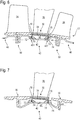
- the figure 6 describes an alternative embodiment of the rotor 12 of the figure 3 .
- the metal wipers 70 are carried by the internal ferrule 32 and rings 72 of abradable material are provided with annular grooves 74 which cooperate with the metal wipers 70.
- the recess 46 has two axial ends 461, 462 and the rings 72 are preferably disposed at these axial ends 461, 462.
- the figure 7 describes another design example of the rotor 12.
- the profile of the segments 40 is U-shaped open outwards.
- Metal wipers 70 cooperate with rings 72 which can be arranged on a bump 46 'of segment 40.
- the figure 8 shows a rotor 12 similar to the previous figures with a seal made differently.
- the seal is a brush seal 80.
- a multitude of bristles extend radially over each of the seals 80.
- the bristles have one end attached to segment 40 and another end that slides over the layer of. abradable 34.
- the bristles can be attached to the abradable layer 34 at one of their ends and can slide over an abradable layer arranged on the segment 40.
- the figure 9 represents an alternative embodiment.
- This example illustrates another variant for the seal between the ferrule and the segments.
- This example also shows a different section for the crown.
- Such a seal design is unrelated to such a crown design.
- FIG 9 illustrates a section crown in the shape of a Greek letter ⁇ , that is to say with an axial branch 52 and two radial branches 54.
- Each of the radial branches of a ring is in contact with a radial termination 44 of a segment 40.
- a joint 90 of J-section is provided between the segment 40 (in particular between its radial terminations 44) and the stator shell 32.
- the seal 90 comprises a main branch 91 fixed to the segment 40 and an auxiliary branch 92 sliding on an annular pad. 94 attached to the ferrule. Screws 96 may be provided to fix the main branch 91 to the segment 40.
Landscapes
- Engineering & Computer Science (AREA)
- Mechanical Engineering (AREA)
- General Engineering & Computer Science (AREA)
- Chemical & Material Sciences (AREA)
- Materials Engineering (AREA)
- Structures Of Non-Positive Displacement Pumps (AREA)
Abstract
Description
- L'invention concerne la conception d'une turbomachine, notamment un turboréacteur d'avion ou un turbopropulseur d'aéronef avec une soufflante entraînée par un réducteur. L'invention a en particulier trait à un rotor de compresseur composé de plusieurs parties dont un tambour en matériau composite.
- Le document
EP 2 818 635 A1 décrit un rotor de compresseur pour turbomachine. Un tambour y est agencé, supportant plusieurs rangées annulaires d'aubes rotoriques dont au moins une aube est monobloc avec le rotor. Cette conception hybride permet un gain de temps lors de la production et de l'assemblage car toutes les aubes ne sont pas monoblocs avec le tambour. Cependant une telle conception peut être améliorée d'un point de vue du poids du rotor. Le poids est un aspect néfaste pour un rotor de compresseur non seulement du fait qu'il nécessite plus d'énergie pour être mis en rotation, réduisant d'autant le rendement du moteur, mais aussi car il va, à sa mesure, participer au poids de l'aéronef et donc au besoin en carburant nécessaire au mouvement de l'aéronef. - Le document
EP 2 287 445 A1 décrit un rotor de compresseur composé de segments en matériau composite et de couronnes métalliques. Ces dernières sont pourvues de rainures en queues d'aronde pour recevoir des aubes rotoriques. - Une telle conception peut présenter des hétérogénéités dans la distribution du poids axialement car les queues d'arondes nécessitent des couronnes métalliques massives. Aussi, il demeure une marge d'amélioration en ce qui concerne l'encombrement général et le poids global du rotor.
- Le taillage ou l'usinage des queues d'arondes présente également l'inconvénient du temps et du coût de fabrication.
- L'invention a pour objectif de proposer un rotor plus léger et dont la fabrication et l'assemblage sont plus économiques.
- L'invention a pour objet un rotor pour compresseur de turbomachine axiale, tel un turboréacteur d'aéronef, comprenant : une pluralité de segments, de forme sensiblement axisymétrique et faits de matériau composite ; une pluralité de rangées annulaires d'aubes rotoriques, chaque rangée d'aubes étant supportée par une couronne respective, métallique et interposée axialement entre deux segments de la pluralité de segments, remarquable en ce que chaque couronne a une section avec une branche axiale chevauchant axialement partiellement les deux segments, les couronnes étant reliées deux à deux uniquement par l'intermédiaire d'un des segments.
- Un tambour est ainsi formé par la succession, selon un axe, de segments et de couronnes qui ne se chevauchent que partiellement et qui forment un ensemble mécaniquement résistant. Le démontage de l'un des éléments (segment ou couronne) rompt le tambour.
- Selon des modes avantageux de l'invention, le rotor peut comprendre une ou plusieurs des caractéristiques suivantes, prises isolément ou selon toutes les combinaisons techniques possibles :
- la section est en T, comprenant une branche radiale, chacun des deux segments ayant une terminaison s'étendant radialement et agencée en appui sur la branche radiale de la couronne ;
- une vis ou un rivet sensiblement axial(e) traverse la branche radiale de la couronne et la terminaison de chacun des deux segments ;
- la branche radiale a une extrémité radiale interne qui comprend une surépaisseur axiale en saillie en amont et en aval de la branche radiale, la surépaisseur définissant deux surfaces radialement externes de centrage des terminaisons des deux segments sur la couronne ;
- la section est en π, comprenant deux branches radiales, chacun des deux segments ayant une terminaison s'étendant radialement et agencée en appui sur une des branches radiales respective de la couronne ;
- la branche axiale dispose d'une surface interne de centrage des deux segments. Cette surface peut être subdivisée en deux surfaces agencées de part et d'autre de la branche ou des branches radiale(s), chacune des deux surfaces coopérant avec l'un des segments ;
- la couronne et les aubes de la rangée d'aubes respective sont monoblocs. Ainsi, elles sont venues de matière ou fabriquées d'un seul tenant. Alternativement, les aubes sont soudées à la couronne ;
- les segments ont une section en U, ouvert radialement vers l'intérieur ou vers l'extérieur ;
- les segments ont une surface externe qui décrit un renfoncement muni de léchettes métalliques radialement en saillie du renfoncement.
- L'invention a également trait à un compresseur de turbomachine comprenant un rotor selon l'un des modes de réalisation exposés ci-dessus et au moins une rangée d'aubes statoriques agencée axialement entre deux rangées annulaires d'aubes rotoriques successives, les aubes statoriques étant supportées par une virole interne chevauchant axialement un segment, et un joint d'étanchéité étant disposé entre la virole interne et le segment.
- Selon des modes avantageux de l'invention, le compresseur peut comprendre une ou plusieurs des caractéristiques suivantes, prises isolément ou selon toutes les combinaisons techniques possibles :
- le joint est fait de léchettes métalliques annulaires sur la virole interne coopérant avec des anneaux de matériau abradable agencés sur le segment ;
- le segment comprend un renfoncement et les anneaux d'abradable sont agencés aux extrémités axiales du renfoncement ;
- le joint est un joint à brosse muni de poils, chacun des poils étant fixé à une de ses extrémités à la virole interne et glissant à son autre extrémité sur le segment ;
- le joint est un joint annulaire de section en J, définissant une branche principale et une branche auxiliaire, la branche principale du J étant fixée au segment et la branche auxiliaire glissant sur un patin annulaire de la virole interne. Alternativement, le joint peut être fixé à la virole et glisser sur le segment ;
- le joint en J est un premier joint et le patin annulaire est un premier patin, disposés en amont de la virole interne, un second joint en J et un second patin annulaire étant disposés en aval de la virole interne ;
- une vis axiale maintient la branche principale du joint au segment et à la couronne, en particulier à la terminaison du segment et à la branche radiale de la couronne.
- L'invention a aussi pour objet un compresseur de turbomachine axiale, tel un turboréacteur d'aéronef, comprenant : un rotor muni d'une pluralité de segments, de forme sensiblement axisymétrique et faits de matériau composite et d'une pluralité de rangées annulaires d'aubes rotoriques supportées par des couronnes agencées entre deux segments adjacents ; au moins une rangée d'aubes statoriques agencée axialement entre deux rangées annulaires d'aubes rotoriques successives, les aubes statoriques étant supportées par une virole interne chevauchant axialement un segment ; et un joint d'étanchéité étant disposé entre la virole interne et un des segments.
- L'invention a également pour objet un procédé d'assemblage d'un rotor selon l'un des modes de réalisations exposés ci-dessus, le procédé comprenant l'empilement alterné de segments et de couronnes et la fixation des couronnes aux segments.
- L'invention a également pour objet un procédé d'assemblage d'un compresseur selon l'un des modes de réalisations exposés ci-dessus, le procédé comprenant l'emmanchement d'un segment en chevauchement axial d'une virole interne de stator, puis la mise en place d'une couronne au contact du segment, suivie de la mise en place d'un second segment contre la couronne, et enfin la fixation par vis ou rivet de la couronne aux deux segments.
- De manière générale, les modes avantageux de chaque objet de l'invention sont également applicables aux autres objets de l'invention. Chaque objet de l'invention est combinable aux autres objets, et les objets de l'invention sont également combinables aux modes de réalisation de la description, qui en plus sont combinables entre eux, selon toutes les combinaisons techniques possibles, à moins que le contraire ne soit explicitement mentionné.
- La conception hybride du rotor selon l'invention permet des gains substantiels en poids comparé à un rotor disposant d'un tambour complètement métallique. Comparé à un rotor monobloc, le temps de fabrication est drastiquement réduit, car plusieurs éléments peuvent être fabriqués en parallèle avant d'être montés ensemble. Aussi, la répartition axiale du poids du rotor est plus homogène.
-
- La
figure 1 représente une turbomachine axiale ; - La
figure 2 représente une vue en coupe schématique d'une partie d'un compresseur de l'état de l'art ; - La
figure 3 représente une vue en coupe du rotor selon un premier mode de réalisation de l'invention ; - La
figure 4 montre une vue en coupe du rotor selon un deuxième mode de réalisation de l'invention ; - La
figure 5 illustre une vue en coupe du rotor selon un troisième mode de réalisation de l'invention ; - La
figure 6 représente une vue en coupe du rotor selon un quatrième mode de réalisation de l'invention ; - La
figure 7 illustre une vue en coupe du rotor selon un cinquième mode de réalisation de l'invention ; - La
figure 8 montre une vue en coupe du rotor selon un sixième mode de réalisation de l'invention ; - La
figure 9 représente une vue en coupe du rotor selon un septième mode de réalisation de l'invention. - Dans la description qui va suivre, les termes « interne » (ou « intérieur ») et « externe » (ou « extérieur ») renvoient à un positionnement par rapport à l'axe de rotation d'une turbomachine axiale. La direction axiale correspond à la direction le long de l'axe de rotation de la turbomachine. La direction radiale est perpendiculaire à l'axe de rotation. L'amont et l'aval sont en référence au sens d'écoulement principal du flux dans la turbomachine. Le terme « solidaire » est compris comme solidaire en rotation, et notamment rigidement lié. Le terme « monobloc » est équivalent à « venu de matière » et désigne différents éléments réalisés dans un même bloc de matière, par opposition à « rapporté » qui signifie qu'un élément est rattaché, après sa fabrication, à un autre élément. Les figures représentent les éléments de manière schématique, notamment sans l'intégralité des éléments d'assemblage ou d'étanchéité. Les dimensions et notamment l'épaisseur radiale, sont exagérées afin de faciliter la compréhension des figures.
- La
figure 1 représente de manière simplifiée une turbomachine axiale 2. Le turboréacteur 2 comprend un premier compresseur, basse-pression 4 et un deuxième compresseur, haute-pression 6, une chambre de combustion 8 et une ou plusieurs turbines 10. En fonctionnement, la puissance mécanique de la turbine 10 transmise au rotor 12 met en mouvement les deux compresseurs 4 et 6. Ces derniers comportent plusieurs rangées d'aubes de rotor associées à des rangées d'aubes de stator. La rotation du rotor autour de son axe de rotation 14 permet ainsi de générer un débit d'air et de comprimer progressivement ce dernier jusqu'à l'entrée de la chambre de combustion 8. - Une soufflante 16 est couplée au rotor 12 et génère un flux d'air qui se divise en un flux primaire 18 et en un flux secondaire 20 traversant un conduit annulaire (partiellement représenté) le long de la machine pour ensuite rejoindre le flux primaire en sortie de turbine.
- Des moyens de démultiplication, tel un réducteur épicycloïdal 22, peuvent réduire la vitesse de rotation de la soufflante et/ou du compresseur basse-pression par rapport à la turbine associée. Le flux secondaire peut être accéléré de sorte à générer une réaction de poussée nécessaire au vol d'un avion.
- La
figure 2 est une vue en coupe d'un compresseur d'une turbomachine axiale connu. Le compresseur peut comprendre un compresseur basse-pression 4. On peut y observer une partie du fan 16 ainsi que le bec de séparation 22 des flux primaire 18 et secondaire 20. Le rotor 12 peut comprendre plusieurs rangées d'aubes rotoriques 24. - Le compresseur basse-pression 4 comprend au moins un redresseur qui contient une rangée annulaire d'aubes statoriques 26. Chaque redresseur est associé au fan 16 ou à une rangée d'aubes rotoriques 24 pour en redresser le flux d'air.
- Le compresseur basse-pression 4 comprend au moins un carter 28. Le carter 28 peut présenter une forme généralement circulaire ou tubulaire. Il peut être un carter externe de compresseur et peut être en matériaux composites. Le carter 28 peut comprendre des brides de fixation 30, par exemple des brides annulaires de fixation 30 pour la fixation du bec de séparation 22 et/ou pour se fixer à un carter intermédiaire de soufflante de la turbomachine. Les brides annulaires 30 peuvent être en composite et comprendre des orifices de fixation (non représentés) pour permettre une fixation par boulons.
- Grâce aux matériaux composites, le carter 28 peut mesurer entre 3 et 5 mm d'épaisseur pour un diamètre supérieur à 1 mètre.
- Les aubes statoriques 26 s'étendent essentiellement radialement depuis le carter 28 jusqu'à des viroles internes 32.
- Dans cet exemple de rotor connu, le rotor 12 est monobloc avec trois rangées annulaires d'aubes rotoriques 24 s'étendant radialement depuis le rotor 12 jusqu'au voisinage du carter 28.
- La
figure 3 illustre en coupe partielle une partie d'un rotor 12 selon l'invention. Le rotor 12 comprend plusieurs segments 40 de matériaux composites. Le matériau composite peut être du type fibre de carbone avec matrice élastomère ou matrice organique. Chaque segment 40 est annulaire et dispose d'une portion centrale 42 sensiblement tubulaire et de deux terminaisons 44 s'étendant radialement. Sur l'exemple de lafigure 3 , les terminaisons 44 s'étendent radialement vers l'intérieur, formant avec la portion centrale 42 un profil en U ouvert vers l'intérieur. - Le rotor 12 comprend également des couronnes 50 interposées entre les segments 40. Les couronnes 50 sont annulaires et faites de matériau métallique. Les couronnes 50 ont une section 51, ayant au moins une branche s'étendant axialement 52 et au moins une branche s'étendant radialement 54. La section peut être en T ou en π (voir l'exemple de la
figure 9 ). La branche axiale 52 surplombe ou chevauche au moins partiellement les segments 40. Par chevauchement, on entend qu'il y a une portion de la couronne 40 et une portion de chacun des segments 50 qui ont la même position axiale. La branche radiale 54 est au contact des terminaisons 44 des segments. Ainsi, une surface 55 de la branche radiale 54 vient arrêter et positionner les segments 40 sur une surface 45. Le contact entre la surface 55 et la surface 45 est axial. - La branche radiale 54 se termine radialement intérieurement par une surépaisseur 56. Celle-ci présente des surfaces 58 qui permettent le centrage des segments 40 par leur contact avec des surface 48 radialement interne des terminaisons 44.
- Les segments 40 peuvent être munis d'un renfoncement 46 aménagé sur leur surface extérieure 47. Celui-ci peut être sous la forme d'une rainure annulaire. Dans ce renfoncement 46 sont aménagés des léchettes métalliques 60 qui peuvent de servir de joint d'étanchéité. Les léchettes 60 viennent en saillie d'un anneau métallique fixé au segment composite 40. Ces léchettes 60 coopèrent avec une couche d'abradable 34 aménagée intérieurement à la virole interne 32 qui supporte les aubes statoriques 26.
- La branche axiale 52 supporte les aubes rotoriques 24. Les aubes 24 peuvent être soudées à la branche axiale 52. Alternativement, les aubes 24 sont monoblocs avec la couronne 50. L'ensemble peut être obtenu, au moins partiellement, par fonderie puis usinage.
- Une rangée annulaire d'éléments de visserie tels des vis axiales 62 peut être prévue pour assembler une couronne 50 à deux segments 40.
- La
figure 4 décrit un mode de réalisation alternatif du rotor 12 de lafigure 3 . Dans cet exemple, le centrage des segments 40 sur la couronne 50 (ou de la couronne 50 sur les segments 40) est réalisé par une surface 49 extérieure au segment 40 au contact d'une surface 59 intérieure de la branche axiale 52 de la couronne 50. - La
figure 5 décrit un mode de réalisation alternatif du rotor 12 de lafigure 3 . Dans cet exemple, la portion centrale 42 des segments 40 est dépourvue de renfoncement et présente donc une surface régulière telle un cône, un cylindre, ou un arc d'ellipsoïde. - La
figure 6 décrit un mode de réalisation alternatif du rotor 12 de lafigure 3 . A l'inverse de lafigure 3 , dans cet exemple, les léchettes métalliques 70 sont portées par la virole interne 32 et des anneaux 72 de matériau abradable sont pourvus de rainures annulaires 74 qui coopèrent avec les léchettes métalliques 70. Le renfoncement 46 a deux extrémités axiales 461, 462 et les anneaux 72 sont préférablement disposés à ces extrémités axiales 461, 462. - La
figure 7 décrit un autre exemple de conception du rotor 12. Dans cet exemple, le profil des segments 40 est en U ouvert vers l'extérieur. Des léchettes métalliques 70 coopèrent avec des anneaux 72 qui peuvent être disposés sur une bosse 46' du segment 40. - La
figure 8 représente un rotor 12 semblable aux figures précédentes avec un joint d'étanchéité réalisé différemment. Dans cet exemple, le joint d'étanchéité est un joint à brosse 80. Une multitude de poils s'étend radialement sur chacun des joints 80. Les poils ont une extrémité attachée au segment 40 et une autre extrémité qui glisse sur la couche d'abradable 34. Alternativement, les poils peuvent être attachés à la couche abradable 34 à l'une de leurs extrémités et peuvent glisser sur une couche d'abradable agencée sur le segment 40. - La
figure 9 représente un mode de réalisation alternatif. Cet exemple illustre une autre variante pour le joint d'étanchéité entre la virole et les segments. Cet exemple illustre également une section différente pour la couronne. Une telle conception de joint n'est pas liée à une telle conception de couronne. - Ainsi, la
figure 9 illustre une couronne de section en forme de lettre grecque π, c'est-à-dire avec une branche axiale 52 et deux branches radiales 54. Chacune des branches radiales d'une couronne est au contact d'une terminaison radiale 44 d'un segment 40. - Un joint 90 de section en J est prévu entre le segment 40 (en particulier entre ses terminaisons radiales 44) et la virole statorique 32. Le joint 90 comprend une branche principale 91 fixée au segment 40 et une branche auxiliaire 92 glissant sur un patin annulaire 94 fixé à la virole. Des vis 96 peuvent être prévues pour fixer la branche principale 91 au segment 40.
- Les différentes figures montrent plusieurs modes de réalisation possibles pour les segments, pour les couronnes et pour les joints. L'homme du métier remarquera que ces trois éléments (segment, couronne, joint) sont interchangeables d'une figure à une autre : notamment, chaque type de joint peut être utilisé avec chaque type de segment et de couronne.
Claims (15)
- Rotor (12) pour compresseur (4, 6) de turbomachine axiale (2), tel un turboréacteur d'aéronef, comprenant :- une pluralité de segments (40), de forme sensiblement axisymétrique et faits de matériau composite ;- une pluralité de rangées annulaires d'aubes rotoriques (24), chaque rangée d'aubes (24) étant supportée par une couronne (50) respective, métallique et interposée axialement entre deux segments (40) de la pluralité de segments (40) ;caractérisé en ce que chaque couronne (50) a une section (51) avec une branche axiale (52) chevauchant axialement partiellement les deux segments (40), les couronnes (50) étant reliées deux à deux uniquement par l'intermédiaire d'un des segments (40).
- Rotor (12) selon la revendication 1, caractérisé en ce que la section (51) est en T (51), comprenant une branche radiale (54), chacun des deux segments (40) ayant une terminaison (44) s'étendant radialement et agencée en appui sur la branche radiale (54) de la couronne (50).
- Rotor (12) selon la revendication précédente, caractérisé en ce qu'une vis (62) ou un rivet sensiblement axial(e) traverse la branche radiale (54) de la couronne (50) et la terminaison (44) de chacun des deux segments (40).
- Rotor (12) selon la revendication 2 ou 3, caractérisé en ce que la branche radiale (54) a une extrémité radiale interne qui comprend une surépaisseur (56) axiale en saillie en amont et en aval de la branche radiale (54), la surépaisseur (56) définissant deux surfaces (58) radialement externes de centrage des terminaisons (44) des deux segments (40) sur la couronne (50).
- Rotor (12) selon la revendication 1, caractérisé en ce que la section (51) est en π (51), comprenant deux branches radiales (54), chacun des deux segments (40) ayant une terminaison (44) s'étendant radialement et agencée en appui sur une des branches radiales (54) respective de la couronne (50).
- Rotor (12) selon l'une des revendications 1 à 3 ou 5, caractérisé en ce que la branche axiale (52) dispose d'une surface interne (59) de centrage des deux segments (40).
- Rotor (12) selon l'une des revendications précédentes, caractérisé en ce que les segments (40) ont une section en U, ouvert radialement vers l'intérieur ou vers l'extérieur.
- Rotor (12) selon l'une des revendications précédentes, caractérisé en ce que les segments (40) ont une surface externe qui décrit un renfoncement (46) muni de léchettes métalliques (60) radialement en saillie du renfoncement (46).
- Compresseur (4, 6) comprenant :- un rotor (12) selon l'une des revendications 1 à 8 ;- au moins une rangée d'aubes statoriques (26) agencée axialement entre deux rangées annulaires d'aubes rotoriques (24) successives,les aubes statoriques (26) étant supportées par une virole interne (32) chevauchant axialement un segment (40), et un joint d'étanchéité (34, 60, 70, 80, 90) étant disposé entre la virole interne (32) et le segment (40).
- Compresseur (4, 6) selon la revendication 9, caractérisé en ce que le joint d'étanchéité (70) est fait de léchettes métalliques (70) annulaires sur la virole interne (32) coopérant avec des anneaux (72) de matériau abradable agencés sur le segment (40).
- Compresseur (4, 6) selon la revendication 9 ou 10, caractérisé en ce que le segment (40) comprend un renfoncement (46) et les anneaux d'abradable (72) sont agencés aux extrémités axiales (461, 462) du renfoncement (46).
- Compresseur (4, 6) selon la revendication 9, caractérisé en ce que le joint d'étanchéité (80) est un joint à brosse (80) muni de poils d'étanchéité, chacun des poils étant fixé à une de ses extrémités à la virole interne (32) et glissant à son autre extrémité sur le segment (40).
- Compresseur (4, 6) selon la revendication 9, caractérisé en ce que le joint (90) est un joint annulaire (90) de section en J, définissant une branche principale (91) et une branche auxiliaire (92), la branche principale (91) du J étant fixée au segment (40) et la branche auxiliaire (92) glissant sur un patin annulaire (94) de la virole interne (32).
- Compresseur (4, 6) selon la revendication 13, caractérisé en ce que le joint (90) en J est un premier joint et le patin annulaire (94) est un premier patin, disposés en amont de la virole interne (32), un second joint (90) en J et un second patin annulaire (94) étant disposés en aval de la virole interne (32).
- Compresseur (4, 6) selon la revendication 13 ou 14, caractérisé en ce qu'une vis axiale (96) maintient la branche principale (91) du joint (90) au segment (40) et à la couronne (50), en particulier à la terminaison (44) du segment (40) et à la ou une des branche(s) radiale(s) (54) de la couronne (50).
Applications Claiming Priority (1)
| Application Number | Priority Date | Filing Date | Title |
|---|---|---|---|
| BE20195063A BE1027025B1 (fr) | 2019-02-04 | 2019-02-04 | Rotor hybride à tambour segmenté |
Publications (2)
| Publication Number | Publication Date |
|---|---|
| EP3690192A1 true EP3690192A1 (fr) | 2020-08-05 |
| EP3690192B1 EP3690192B1 (fr) | 2023-05-10 |
Family
ID=65440728
Family Applications (1)
| Application Number | Title | Priority Date | Filing Date |
|---|---|---|---|
| EP20150739.9A Active EP3690192B1 (fr) | 2019-02-04 | 2020-01-08 | Rotor pour compresseur de turbomachine axiale |
Country Status (4)
| Country | Link |
|---|---|
| US (1) | US11346224B2 (fr) |
| EP (1) | EP3690192B1 (fr) |
| CN (1) | CN111520360B (fr) |
| BE (1) | BE1027025B1 (fr) |
Cited By (1)
| Publication number | Priority date | Publication date | Assignee | Title |
|---|---|---|---|---|
| FR3117147A1 (fr) * | 2020-12-09 | 2022-06-10 | Safran Aircraft Engines | Ensemble statorique de turbine avec degré de liberté radial entre un distributeur et un anneau d’étanchéité |
Families Citing this family (1)
| Publication number | Priority date | Publication date | Assignee | Title |
|---|---|---|---|---|
| CN112943685B (zh) * | 2021-03-10 | 2022-09-13 | 哈电发电设备国家工程研究中心有限公司 | 一种拉杆式叶根连接结构 |
Citations (6)
| Publication number | Priority date | Publication date | Assignee | Title |
|---|---|---|---|---|
| US5632600A (en) * | 1995-12-22 | 1997-05-27 | General Electric Company | Reinforced rotor disk assembly |
| US6213720B1 (en) * | 1999-06-11 | 2001-04-10 | Alliedsignal, Inc. | High strength composite reinforced turbomachinery disk |
| EP2287445A1 (fr) | 2009-07-16 | 2011-02-23 | Techspace Aero S.A. | Tambour de rotor de compresseur axial avec voile composite |
| EP2801702A1 (fr) * | 2013-05-10 | 2014-11-12 | Techspace Aero S.A. | Virole interne de redresseur de turbomachine avec abradable |
| EP2818635A1 (fr) | 2013-06-25 | 2014-12-31 | Techspace Aero S.A. | Tambour de compresseur de turbomachine axiale avec fixation mixte d'aubes |
| WO2016059348A1 (fr) * | 2014-10-15 | 2016-04-21 | Snecma | Ensemble rotatif pour turbomachine comprenant une virole de rotor auto-portee |
Family Cites Families (8)
| Publication number | Priority date | Publication date | Assignee | Title |
|---|---|---|---|---|
| FR2875842B1 (fr) * | 2004-09-28 | 2010-09-24 | Snecma Moteurs | Dispositif de limitation de survitesse de turbine dans une turbomachine |
| US7155800B2 (en) * | 2005-02-24 | 2007-01-02 | General Electric Company | Automated seal strip assembly method and apparatus for rotary machines |
| US8402625B2 (en) * | 2011-08-30 | 2013-03-26 | General Electric Company | System and method for modifying a rotor |
| EP2843196B1 (fr) * | 2013-09-03 | 2020-04-15 | Safran Aero Boosters SA | Compresseur de turbomachine et turboachine associée |
| FR3027341B1 (fr) * | 2014-10-15 | 2020-10-23 | Snecma | Ensemble rotatif pour turbomachine comprenant une virole de rotor auto-portee |
| BE1022481B1 (fr) * | 2014-10-28 | 2016-05-02 | Techspace Aero S.A. | Aube a treillis de compresseur de turbomachine axiale |
| BE1023233B1 (fr) * | 2015-07-01 | 2017-01-05 | Safran Aero Boosters S.A. | Tambour perfore de compresseur de turbomachine axiale |
| US10823012B2 (en) * | 2016-05-20 | 2020-11-03 | Raytheon Technologies Corporation | Fastener openings for stress distribution |
-
2019
- 2019-02-04 BE BE20195063A patent/BE1027025B1/fr active IP Right Grant
-
2020
- 2020-01-08 EP EP20150739.9A patent/EP3690192B1/fr active Active
- 2020-01-20 US US16/747,371 patent/US11346224B2/en active Active
- 2020-02-03 CN CN202010078251.7A patent/CN111520360B/zh active Active
Patent Citations (6)
| Publication number | Priority date | Publication date | Assignee | Title |
|---|---|---|---|---|
| US5632600A (en) * | 1995-12-22 | 1997-05-27 | General Electric Company | Reinforced rotor disk assembly |
| US6213720B1 (en) * | 1999-06-11 | 2001-04-10 | Alliedsignal, Inc. | High strength composite reinforced turbomachinery disk |
| EP2287445A1 (fr) | 2009-07-16 | 2011-02-23 | Techspace Aero S.A. | Tambour de rotor de compresseur axial avec voile composite |
| EP2801702A1 (fr) * | 2013-05-10 | 2014-11-12 | Techspace Aero S.A. | Virole interne de redresseur de turbomachine avec abradable |
| EP2818635A1 (fr) | 2013-06-25 | 2014-12-31 | Techspace Aero S.A. | Tambour de compresseur de turbomachine axiale avec fixation mixte d'aubes |
| WO2016059348A1 (fr) * | 2014-10-15 | 2016-04-21 | Snecma | Ensemble rotatif pour turbomachine comprenant une virole de rotor auto-portee |
Cited By (3)
| Publication number | Priority date | Publication date | Assignee | Title |
|---|---|---|---|---|
| FR3117147A1 (fr) * | 2020-12-09 | 2022-06-10 | Safran Aircraft Engines | Ensemble statorique de turbine avec degré de liberté radial entre un distributeur et un anneau d’étanchéité |
| WO2022123157A1 (fr) * | 2020-12-09 | 2022-06-16 | Safran Aircraft Engines | Ensemble statorique de turbine avec degré de liberté radial entre un distributeur et un anneau d'étanchéité |
| US12116897B2 (en) | 2020-12-09 | 2024-10-15 | Safran Aircraft Engines | Turbine stator assembly with a radial degree of freedom between a guide vane assembly and a sealing ring |
Also Published As
| Publication number | Publication date |
|---|---|
| CN111520360A (zh) | 2020-08-11 |
| CN111520360B (zh) | 2024-04-12 |
| BE1027025A1 (fr) | 2020-08-27 |
| BE1027025B1 (fr) | 2020-09-02 |
| US20200248556A1 (en) | 2020-08-06 |
| EP3690192B1 (fr) | 2023-05-10 |
| US11346224B2 (en) | 2022-05-31 |
Similar Documents
| Publication | Publication Date | Title |
|---|---|---|
| EP2801702B1 (fr) | Virole interne de redresseur de turbomachine avec joint abradable | |
| EP3109406B1 (fr) | Carter de compresseur de turbomachine axiale | |
| EP2199544B1 (fr) | Architecture de redresseur | |
| EP2811121B1 (fr) | Carter composite de compresseur de turbomachine axiale avec bride de fixation métallique | |
| EP3810903B1 (fr) | Virole extérieure de turbomachine | |
| EP2821595B1 (fr) | Secteur d'aubes statorique à fixation mixte pour turbomachine axiale | |
| EP3690192B1 (fr) | Rotor pour compresseur de turbomachine axiale | |
| EP3409902A1 (fr) | Système d'étanchéité pour compresseur de turbomachine | |
| EP3973146B1 (fr) | Pion amovible sur distributeur de turbomachine | |
| EP3382242B1 (fr) | Joint à brosse pour rotor de turbomachine | |
| EP3751102B1 (fr) | Rotor pour compresseur de turbomachine et procédé de montage associé | |
| EP3553322B1 (fr) | Ensemble pour turbomachine axiale avec virole exterieure en deux parties | |
| EP3726006B1 (fr) | Rotor hybride avec inserts | |
| BE1027280B1 (fr) | Carter de compresseur pour turbomachine | |
| BE1029166B1 (fr) | Carter pour compresseur de turbomachine | |
| EP3715638B1 (fr) | Rotor hybride à coquille externe rapportée contre la paroi annulaire composite | |
| EP3382155B1 (fr) | Système d'étanchéité pour turbomachine et turbomachine associée | |
| BE1026460B1 (fr) | Carter structural pour turbomachine axiale | |
| EP4288668B1 (fr) | Ensemble redresseur pour compresseur de turbomachine d'aeronef | |
| BE1023367A1 (fr) | Fixation de virole interne de compresseur de turbomachine axiale |
Legal Events
| Date | Code | Title | Description |
|---|---|---|---|
| PUAI | Public reference made under article 153(3) epc to a published international application that has entered the european phase |
Free format text: ORIGINAL CODE: 0009012 |
|
| STAA | Information on the status of an ep patent application or granted ep patent |
Free format text: STATUS: THE APPLICATION HAS BEEN PUBLISHED |
|
| AK | Designated contracting states |
Kind code of ref document: A1 Designated state(s): AL AT BE BG CH CY CZ DE DK EE ES FI FR GB GR HR HU IE IS IT LI LT LU LV MC MK MT NL NO PL PT RO RS SE SI SK SM TR |
|
| AX | Request for extension of the european patent |
Extension state: BA ME |
|
| STAA | Information on the status of an ep patent application or granted ep patent |
Free format text: STATUS: REQUEST FOR EXAMINATION WAS MADE |
|
| 17P | Request for examination filed |
Effective date: 20210202 |
|
| RBV | Designated contracting states (corrected) |
Designated state(s): AL AT BE BG CH CY CZ DE DK EE ES FI FR GB GR HR HU IE IS IT LI LT LU LV MC MK MT NL NO PL PT RO RS SE SI SK SM TR |
|
| STAA | Information on the status of an ep patent application or granted ep patent |
Free format text: STATUS: EXAMINATION IS IN PROGRESS |
|
| 17Q | First examination report despatched |
Effective date: 20211015 |
|
| RIC1 | Information provided on ipc code assigned before grant |
Ipc: F01D 11/12 19950101ALN20230111BHEP Ipc: F01D 11/02 19680901ALN20230111BHEP Ipc: F01D 5/06 19680901ALN20230111BHEP Ipc: F01D 11/00 19680901AFI20230111BHEP |
|
| GRAP | Despatch of communication of intention to grant a patent |
Free format text: ORIGINAL CODE: EPIDOSNIGR1 |
|
| STAA | Information on the status of an ep patent application or granted ep patent |
Free format text: STATUS: GRANT OF PATENT IS INTENDED |
|
| INTG | Intention to grant announced |
Effective date: 20230217 |
|
| GRAS | Grant fee paid |
Free format text: ORIGINAL CODE: EPIDOSNIGR3 |
|
| GRAA | (expected) grant |
Free format text: ORIGINAL CODE: 0009210 |
|
| STAA | Information on the status of an ep patent application or granted ep patent |
Free format text: STATUS: THE PATENT HAS BEEN GRANTED |
|
| AK | Designated contracting states |
Kind code of ref document: B1 Designated state(s): AL AT BE BG CH CY CZ DE DK EE ES FI FR GB GR HR HU IE IS IT LI LT LU LV MC MK MT NL NO PL PT RO RS SE SI SK SM TR |
|
| REG | Reference to a national code |
Ref country code: GB Ref legal event code: FG4D Free format text: NOT ENGLISH |
|
| REG | Reference to a national code |
Ref country code: AT Ref legal event code: REF Ref document number: 1566869 Country of ref document: AT Kind code of ref document: T Effective date: 20230515 Ref country code: CH Ref legal event code: EP |
|
| REG | Reference to a national code |
Ref country code: DE Ref legal event code: R096 Ref document number: 602020010548 Country of ref document: DE |
|
| REG | Reference to a national code |
Ref country code: IE Ref legal event code: FG4D Free format text: LANGUAGE OF EP DOCUMENT: FRENCH |
|
| REG | Reference to a national code |
Ref country code: LT Ref legal event code: MG9D |
|
| REG | Reference to a national code |
Ref country code: NL Ref legal event code: MP Effective date: 20230510 |
|
| REG | Reference to a national code |
Ref country code: AT Ref legal event code: MK05 Ref document number: 1566869 Country of ref document: AT Kind code of ref document: T Effective date: 20230510 |
|
| PG25 | Lapsed in a contracting state [announced via postgrant information from national office to epo] |
Ref country code: SE Free format text: LAPSE BECAUSE OF FAILURE TO SUBMIT A TRANSLATION OF THE DESCRIPTION OR TO PAY THE FEE WITHIN THE PRESCRIBED TIME-LIMIT Effective date: 20230510 Ref country code: PT Free format text: LAPSE BECAUSE OF FAILURE TO SUBMIT A TRANSLATION OF THE DESCRIPTION OR TO PAY THE FEE WITHIN THE PRESCRIBED TIME-LIMIT Effective date: 20230911 Ref country code: NO Free format text: LAPSE BECAUSE OF FAILURE TO SUBMIT A TRANSLATION OF THE DESCRIPTION OR TO PAY THE FEE WITHIN THE PRESCRIBED TIME-LIMIT Effective date: 20230810 Ref country code: NL Free format text: LAPSE BECAUSE OF FAILURE TO SUBMIT A TRANSLATION OF THE DESCRIPTION OR TO PAY THE FEE WITHIN THE PRESCRIBED TIME-LIMIT Effective date: 20230510 Ref country code: ES Free format text: LAPSE BECAUSE OF FAILURE TO SUBMIT A TRANSLATION OF THE DESCRIPTION OR TO PAY THE FEE WITHIN THE PRESCRIBED TIME-LIMIT Effective date: 20230510 Ref country code: AT Free format text: LAPSE BECAUSE OF FAILURE TO SUBMIT A TRANSLATION OF THE DESCRIPTION OR TO PAY THE FEE WITHIN THE PRESCRIBED TIME-LIMIT Effective date: 20230510 |
|
| PG25 | Lapsed in a contracting state [announced via postgrant information from national office to epo] |
Ref country code: RS Free format text: LAPSE BECAUSE OF FAILURE TO SUBMIT A TRANSLATION OF THE DESCRIPTION OR TO PAY THE FEE WITHIN THE PRESCRIBED TIME-LIMIT Effective date: 20230510 Ref country code: PL Free format text: LAPSE BECAUSE OF FAILURE TO SUBMIT A TRANSLATION OF THE DESCRIPTION OR TO PAY THE FEE WITHIN THE PRESCRIBED TIME-LIMIT Effective date: 20230510 Ref country code: LV Free format text: LAPSE BECAUSE OF FAILURE TO SUBMIT A TRANSLATION OF THE DESCRIPTION OR TO PAY THE FEE WITHIN THE PRESCRIBED TIME-LIMIT Effective date: 20230510 Ref country code: LT Free format text: LAPSE BECAUSE OF FAILURE TO SUBMIT A TRANSLATION OF THE DESCRIPTION OR TO PAY THE FEE WITHIN THE PRESCRIBED TIME-LIMIT Effective date: 20230510 Ref country code: IS Free format text: LAPSE BECAUSE OF FAILURE TO SUBMIT A TRANSLATION OF THE DESCRIPTION OR TO PAY THE FEE WITHIN THE PRESCRIBED TIME-LIMIT Effective date: 20230910 Ref country code: HR Free format text: LAPSE BECAUSE OF FAILURE TO SUBMIT A TRANSLATION OF THE DESCRIPTION OR TO PAY THE FEE WITHIN THE PRESCRIBED TIME-LIMIT Effective date: 20230510 Ref country code: GR Free format text: LAPSE BECAUSE OF FAILURE TO SUBMIT A TRANSLATION OF THE DESCRIPTION OR TO PAY THE FEE WITHIN THE PRESCRIBED TIME-LIMIT Effective date: 20230811 |
|
| PG25 | Lapsed in a contracting state [announced via postgrant information from national office to epo] |
Ref country code: FI Free format text: LAPSE BECAUSE OF FAILURE TO SUBMIT A TRANSLATION OF THE DESCRIPTION OR TO PAY THE FEE WITHIN THE PRESCRIBED TIME-LIMIT Effective date: 20230510 |
|
| PG25 | Lapsed in a contracting state [announced via postgrant information from national office to epo] |
Ref country code: SK Free format text: LAPSE BECAUSE OF FAILURE TO SUBMIT A TRANSLATION OF THE DESCRIPTION OR TO PAY THE FEE WITHIN THE PRESCRIBED TIME-LIMIT Effective date: 20230510 |
|
| PG25 | Lapsed in a contracting state [announced via postgrant information from national office to epo] |
Ref country code: SM Free format text: LAPSE BECAUSE OF FAILURE TO SUBMIT A TRANSLATION OF THE DESCRIPTION OR TO PAY THE FEE WITHIN THE PRESCRIBED TIME-LIMIT Effective date: 20230510 Ref country code: SK Free format text: LAPSE BECAUSE OF FAILURE TO SUBMIT A TRANSLATION OF THE DESCRIPTION OR TO PAY THE FEE WITHIN THE PRESCRIBED TIME-LIMIT Effective date: 20230510 Ref country code: RO Free format text: LAPSE BECAUSE OF FAILURE TO SUBMIT A TRANSLATION OF THE DESCRIPTION OR TO PAY THE FEE WITHIN THE PRESCRIBED TIME-LIMIT Effective date: 20230510 Ref country code: EE Free format text: LAPSE BECAUSE OF FAILURE TO SUBMIT A TRANSLATION OF THE DESCRIPTION OR TO PAY THE FEE WITHIN THE PRESCRIBED TIME-LIMIT Effective date: 20230510 Ref country code: DK Free format text: LAPSE BECAUSE OF FAILURE TO SUBMIT A TRANSLATION OF THE DESCRIPTION OR TO PAY THE FEE WITHIN THE PRESCRIBED TIME-LIMIT Effective date: 20230510 Ref country code: CZ Free format text: LAPSE BECAUSE OF FAILURE TO SUBMIT A TRANSLATION OF THE DESCRIPTION OR TO PAY THE FEE WITHIN THE PRESCRIBED TIME-LIMIT Effective date: 20230510 |
|
| REG | Reference to a national code |
Ref country code: DE Ref legal event code: R097 Ref document number: 602020010548 Country of ref document: DE |
|
| PLBE | No opposition filed within time limit |
Free format text: ORIGINAL CODE: 0009261 |
|
| STAA | Information on the status of an ep patent application or granted ep patent |
Free format text: STATUS: NO OPPOSITION FILED WITHIN TIME LIMIT |
|
| 26N | No opposition filed |
Effective date: 20240213 |
|
| PG25 | Lapsed in a contracting state [announced via postgrant information from national office to epo] |
Ref country code: SI Free format text: LAPSE BECAUSE OF FAILURE TO SUBMIT A TRANSLATION OF THE DESCRIPTION OR TO PAY THE FEE WITHIN THE PRESCRIBED TIME-LIMIT Effective date: 20230510 |
|
| PG25 | Lapsed in a contracting state [announced via postgrant information from national office to epo] |
Ref country code: SI Free format text: LAPSE BECAUSE OF FAILURE TO SUBMIT A TRANSLATION OF THE DESCRIPTION OR TO PAY THE FEE WITHIN THE PRESCRIBED TIME-LIMIT Effective date: 20230510 Ref country code: IT Free format text: LAPSE BECAUSE OF FAILURE TO SUBMIT A TRANSLATION OF THE DESCRIPTION OR TO PAY THE FEE WITHIN THE PRESCRIBED TIME-LIMIT Effective date: 20230510 |
|
| PG25 | Lapsed in a contracting state [announced via postgrant information from national office to epo] |
Ref country code: MC Free format text: LAPSE BECAUSE OF FAILURE TO SUBMIT A TRANSLATION OF THE DESCRIPTION OR TO PAY THE FEE WITHIN THE PRESCRIBED TIME-LIMIT Effective date: 20230510 |
|
| PG25 | Lapsed in a contracting state [announced via postgrant information from national office to epo] |
Ref country code: MC Free format text: LAPSE BECAUSE OF FAILURE TO SUBMIT A TRANSLATION OF THE DESCRIPTION OR TO PAY THE FEE WITHIN THE PRESCRIBED TIME-LIMIT Effective date: 20230510 |
|
| REG | Reference to a national code |
Ref country code: CH Ref legal event code: PL |
|
| PG25 | Lapsed in a contracting state [announced via postgrant information from national office to epo] |
Ref country code: LU Free format text: LAPSE BECAUSE OF NON-PAYMENT OF DUE FEES Effective date: 20240108 |
|
| PG25 | Lapsed in a contracting state [announced via postgrant information from national office to epo] |
Ref country code: LU Free format text: LAPSE BECAUSE OF NON-PAYMENT OF DUE FEES Effective date: 20240108 |
|
| PG25 | Lapsed in a contracting state [announced via postgrant information from national office to epo] |
Ref country code: CH Free format text: LAPSE BECAUSE OF NON-PAYMENT OF DUE FEES Effective date: 20240131 |
|
| PG25 | Lapsed in a contracting state [announced via postgrant information from national office to epo] |
Ref country code: CH Free format text: LAPSE BECAUSE OF NON-PAYMENT OF DUE FEES Effective date: 20240131 |
|
| PG25 | Lapsed in a contracting state [announced via postgrant information from national office to epo] |
Ref country code: BG Free format text: LAPSE BECAUSE OF FAILURE TO SUBMIT A TRANSLATION OF THE DESCRIPTION OR TO PAY THE FEE WITHIN THE PRESCRIBED TIME-LIMIT Effective date: 20230510 |
|
| PG25 | Lapsed in a contracting state [announced via postgrant information from national office to epo] |
Ref country code: BG Free format text: LAPSE BECAUSE OF FAILURE TO SUBMIT A TRANSLATION OF THE DESCRIPTION OR TO PAY THE FEE WITHIN THE PRESCRIBED TIME-LIMIT Effective date: 20230510 |
|
| PGFP | Annual fee paid to national office [announced via postgrant information from national office to epo] |
Ref country code: BE Payment date: 20241218 Year of fee payment: 6 |
|
| PGFP | Annual fee paid to national office [announced via postgrant information from national office to epo] |
Ref country code: GB Payment date: 20241224 Year of fee payment: 6 |
|
| PGFP | Annual fee paid to national office [announced via postgrant information from national office to epo] |
Ref country code: FR Payment date: 20241220 Year of fee payment: 6 |
|
| PG25 | Lapsed in a contracting state [announced via postgrant information from national office to epo] |
Ref country code: IE Free format text: LAPSE BECAUSE OF NON-PAYMENT OF DUE FEES Effective date: 20240108 |
|
| PG25 | Lapsed in a contracting state [announced via postgrant information from national office to epo] |
Ref country code: IE Free format text: LAPSE BECAUSE OF NON-PAYMENT OF DUE FEES Effective date: 20240108 |
|
| PGFP | Annual fee paid to national office [announced via postgrant information from national office to epo] |
Ref country code: DE Payment date: 20241218 Year of fee payment: 6 |
|
| PG25 | Lapsed in a contracting state [announced via postgrant information from national office to epo] |
Ref country code: CY Free format text: LAPSE BECAUSE OF FAILURE TO SUBMIT A TRANSLATION OF THE DESCRIPTION OR TO PAY THE FEE WITHIN THE PRESCRIBED TIME-LIMIT; INVALID AB INITIO Effective date: 20200108 |
|
| PG25 | Lapsed in a contracting state [announced via postgrant information from national office to epo] |
Ref country code: HU Free format text: LAPSE BECAUSE OF FAILURE TO SUBMIT A TRANSLATION OF THE DESCRIPTION OR TO PAY THE FEE WITHIN THE PRESCRIBED TIME-LIMIT; INVALID AB INITIO Effective date: 20200108 |
|
| PG25 | Lapsed in a contracting state [announced via postgrant information from national office to epo] |
Ref country code: TR Free format text: LAPSE BECAUSE OF FAILURE TO SUBMIT A TRANSLATION OF THE DESCRIPTION OR TO PAY THE FEE WITHIN THE PRESCRIBED TIME-LIMIT Effective date: 20230510 |