EP3690066A1 - Method for adjusting melting-refining furnace and melting-refining furnace - Google Patents
Method for adjusting melting-refining furnace and melting-refining furnace Download PDFInfo
- Publication number
- EP3690066A1 EP3690066A1 EP17927214.1A EP17927214A EP3690066A1 EP 3690066 A1 EP3690066 A1 EP 3690066A1 EP 17927214 A EP17927214 A EP 17927214A EP 3690066 A1 EP3690066 A1 EP 3690066A1
- Authority
- EP
- European Patent Office
- Prior art keywords
- furnace
- melting
- refining
- iron source
- burner
- Prior art date
- Legal status (The legal status is an assumption and is not a legal conclusion. Google has not performed a legal analysis and makes no representation as to the accuracy of the status listed.)
- Pending
Links
Images


Classifications
-
- F—MECHANICAL ENGINEERING; LIGHTING; HEATING; WEAPONS; BLASTING
- F27—FURNACES; KILNS; OVENS; RETORTS
- F27D—DETAILS OR ACCESSORIES OF FURNACES, KILNS, OVENS OR RETORTS, IN SO FAR AS THEY ARE OF KINDS OCCURRING IN MORE THAN ONE KIND OF FURNACE
- F27D3/00—Charging; Discharging; Manipulation of charge
- F27D3/0025—Charging or loading melting furnaces with material in the solid state
-
- C—CHEMISTRY; METALLURGY
- C21—METALLURGY OF IRON
- C21B—MANUFACTURE OF IRON OR STEEL
- C21B13/00—Making spongy iron or liquid steel, by direct processes
- C21B13/12—Making spongy iron or liquid steel, by direct processes in electric furnaces
-
- C—CHEMISTRY; METALLURGY
- C21—METALLURGY OF IRON
- C21C—PROCESSING OF PIG-IRON, e.g. REFINING, MANUFACTURE OF WROUGHT-IRON OR STEEL; TREATMENT IN MOLTEN STATE OF FERROUS ALLOYS
- C21C5/00—Manufacture of carbon-steel, e.g. plain mild steel, medium carbon steel or cast steel or stainless steel
- C21C5/52—Manufacture of steel in electric furnaces
-
- C—CHEMISTRY; METALLURGY
- C21—METALLURGY OF IRON
- C21C—PROCESSING OF PIG-IRON, e.g. REFINING, MANUFACTURE OF WROUGHT-IRON OR STEEL; TREATMENT IN MOLTEN STATE OF FERROUS ALLOYS
- C21C5/00—Manufacture of carbon-steel, e.g. plain mild steel, medium carbon steel or cast steel or stainless steel
- C21C5/52—Manufacture of steel in electric furnaces
- C21C5/5211—Manufacture of steel in electric furnaces in an alternating current [AC] electric arc furnace
- C21C5/5217—Manufacture of steel in electric furnaces in an alternating current [AC] electric arc furnace equipped with burners or devices for injecting gas, i.e. oxygen, or pulverulent materials into the furnace
-
- F—MECHANICAL ENGINEERING; LIGHTING; HEATING; WEAPONS; BLASTING
- F27—FURNACES; KILNS; OVENS; RETORTS
- F27B—FURNACES, KILNS, OVENS OR RETORTS IN GENERAL; OPEN SINTERING OR LIKE APPARATUS
- F27B14/00—Crucible or pot furnaces
- F27B14/06—Crucible or pot furnaces heated electrically, e.g. induction crucible furnaces with or without any other source of heat
-
- F—MECHANICAL ENGINEERING; LIGHTING; HEATING; WEAPONS; BLASTING
- F27—FURNACES; KILNS; OVENS; RETORTS
- F27B—FURNACES, KILNS, OVENS OR RETORTS IN GENERAL; OPEN SINTERING OR LIKE APPARATUS
- F27B3/00—Hearth-type furnaces, e.g. of reverberatory type; Electric arc furnaces ; Tank furnaces
- F27B3/08—Hearth-type furnaces, e.g. of reverberatory type; Electric arc furnaces ; Tank furnaces heated electrically, with or without any other source of heat
- F27B3/085—Arc furnaces
-
- F—MECHANICAL ENGINEERING; LIGHTING; HEATING; WEAPONS; BLASTING
- F27—FURNACES; KILNS; OVENS; RETORTS
- F27B—FURNACES, KILNS, OVENS OR RETORTS IN GENERAL; OPEN SINTERING OR LIKE APPARATUS
- F27B3/00—Hearth-type furnaces, e.g. of reverberatory type; Electric arc furnaces ; Tank furnaces
- F27B3/10—Details, accessories or equipment, e.g. dust-collectors, specially adapted for hearth-type furnaces
- F27B3/20—Arrangements of heating devices
- F27B3/205—Burners
-
- F—MECHANICAL ENGINEERING; LIGHTING; HEATING; WEAPONS; BLASTING
- F27—FURNACES; KILNS; OVENS; RETORTS
- F27B—FURNACES, KILNS, OVENS OR RETORTS IN GENERAL; OPEN SINTERING OR LIKE APPARATUS
- F27B3/00—Hearth-type furnaces, e.g. of reverberatory type; Electric arc furnaces ; Tank furnaces
- F27B3/10—Details, accessories or equipment, e.g. dust-collectors, specially adapted for hearth-type furnaces
- F27B3/22—Arrangements of air or gas supply devices
- F27B3/225—Oxygen blowing
-
- F—MECHANICAL ENGINEERING; LIGHTING; HEATING; WEAPONS; BLASTING
- F27—FURNACES; KILNS; OVENS; RETORTS
- F27D—DETAILS OR ACCESSORIES OF FURNACES, KILNS, OVENS OR RETORTS, IN SO FAR AS THEY ARE OF KINDS OCCURRING IN MORE THAN ONE KIND OF FURNACE
- F27D11/00—Arrangement of elements for electric heating in or on furnaces
- F27D11/08—Heating by electric discharge, e.g. arc discharge
- F27D11/10—Disposition of electrodes
-
- F—MECHANICAL ENGINEERING; LIGHTING; HEATING; WEAPONS; BLASTING
- F27—FURNACES; KILNS; OVENS; RETORTS
- F27D—DETAILS OR ACCESSORIES OF FURNACES, KILNS, OVENS OR RETORTS, IN SO FAR AS THEY ARE OF KINDS OCCURRING IN MORE THAN ONE KIND OF FURNACE
- F27D19/00—Arrangements of controlling devices
-
- F—MECHANICAL ENGINEERING; LIGHTING; HEATING; WEAPONS; BLASTING
- F27—FURNACES; KILNS; OVENS; RETORTS
- F27D—DETAILS OR ACCESSORIES OF FURNACES, KILNS, OVENS OR RETORTS, IN SO FAR AS THEY ARE OF KINDS OCCURRING IN MORE THAN ONE KIND OF FURNACE
- F27D3/00—Charging; Discharging; Manipulation of charge
- F27D3/16—Introducing a fluid jet or current into the charge
-
- F—MECHANICAL ENGINEERING; LIGHTING; HEATING; WEAPONS; BLASTING
- F27—FURNACES; KILNS; OVENS; RETORTS
- F27D—DETAILS OR ACCESSORIES OF FURNACES, KILNS, OVENS OR RETORTS, IN SO FAR AS THEY ARE OF KINDS OCCURRING IN MORE THAN ONE KIND OF FURNACE
- F27D99/00—Subject matter not provided for in other groups of this subclass
- F27D99/0001—Heating elements or systems
- F27D99/0033—Heating elements or systems using burners
-
- C—CHEMISTRY; METALLURGY
- C21—METALLURGY OF IRON
- C21C—PROCESSING OF PIG-IRON, e.g. REFINING, MANUFACTURE OF WROUGHT-IRON OR STEEL; TREATMENT IN MOLTEN STATE OF FERROUS ALLOYS
- C21C5/00—Manufacture of carbon-steel, e.g. plain mild steel, medium carbon steel or cast steel or stainless steel
- C21C5/52—Manufacture of steel in electric furnaces
- C21C5/5211—Manufacture of steel in electric furnaces in an alternating current [AC] electric arc furnace
- C21C2005/5223—Manufacture of steel in electric furnaces in an alternating current [AC] electric arc furnace with post-combustion
-
- F—MECHANICAL ENGINEERING; LIGHTING; HEATING; WEAPONS; BLASTING
- F27—FURNACES; KILNS; OVENS; RETORTS
- F27D—DETAILS OR ACCESSORIES OF FURNACES, KILNS, OVENS OR RETORTS, IN SO FAR AS THEY ARE OF KINDS OCCURRING IN MORE THAN ONE KIND OF FURNACE
- F27D3/00—Charging; Discharging; Manipulation of charge
- F27D3/16—Introducing a fluid jet or current into the charge
- F27D2003/162—Introducing a fluid jet or current into the charge the fluid being an oxidant or a fuel
-
- F—MECHANICAL ENGINEERING; LIGHTING; HEATING; WEAPONS; BLASTING
- F27—FURNACES; KILNS; OVENS; RETORTS
- F27D—DETAILS OR ACCESSORIES OF FURNACES, KILNS, OVENS OR RETORTS, IN SO FAR AS THEY ARE OF KINDS OCCURRING IN MORE THAN ONE KIND OF FURNACE
- F27D3/00—Charging; Discharging; Manipulation of charge
- F27D3/16—Introducing a fluid jet or current into the charge
- F27D2003/162—Introducing a fluid jet or current into the charge the fluid being an oxidant or a fuel
- F27D2003/163—Introducing a fluid jet or current into the charge the fluid being an oxidant or a fuel the fluid being an oxidant
- F27D2003/164—Oxygen
-
- F—MECHANICAL ENGINEERING; LIGHTING; HEATING; WEAPONS; BLASTING
- F27—FURNACES; KILNS; OVENS; RETORTS
- F27D—DETAILS OR ACCESSORIES OF FURNACES, KILNS, OVENS OR RETORTS, IN SO FAR AS THEY ARE OF KINDS OCCURRING IN MORE THAN ONE KIND OF FURNACE
- F27D3/00—Charging; Discharging; Manipulation of charge
- F27D3/16—Introducing a fluid jet or current into the charge
- F27D2003/168—Introducing a fluid jet or current into the charge through a lance
-
- F—MECHANICAL ENGINEERING; LIGHTING; HEATING; WEAPONS; BLASTING
- F27—FURNACES; KILNS; OVENS; RETORTS
- F27D—DETAILS OR ACCESSORIES OF FURNACES, KILNS, OVENS OR RETORTS, IN SO FAR AS THEY ARE OF KINDS OCCURRING IN MORE THAN ONE KIND OF FURNACE
- F27D19/00—Arrangements of controlling devices
- F27D2019/0028—Regulation
- F27D2019/0034—Regulation through control of a heating quantity such as fuel, oxidant or intensity of current
-
- Y—GENERAL TAGGING OF NEW TECHNOLOGICAL DEVELOPMENTS; GENERAL TAGGING OF CROSS-SECTIONAL TECHNOLOGIES SPANNING OVER SEVERAL SECTIONS OF THE IPC; TECHNICAL SUBJECTS COVERED BY FORMER USPC CROSS-REFERENCE ART COLLECTIONS [XRACs] AND DIGESTS
- Y02—TECHNOLOGIES OR APPLICATIONS FOR MITIGATION OR ADAPTATION AGAINST CLIMATE CHANGE
- Y02P—CLIMATE CHANGE MITIGATION TECHNOLOGIES IN THE PRODUCTION OR PROCESSING OF GOODS
- Y02P10/00—Technologies related to metal processing
- Y02P10/20—Recycling
Definitions
- the present invention relates to a method for operating a melting/refining furnace using an oxygen burner and a lance and a melting/refining furnace.
- Burners which heat an object to be heated by burning an oxidant gas (oxygen, air, oxygen-enriched air, and the like) containing oxygen and fuel are used in various production processes.
- an oxidant gas oxygen, air, oxygen-enriched air, and the like
- a raw material such as iron scraps
- a low temperature region called a cold spot is generated in the raw material, and the raw material may be difficult to melt in this region.
- the combined use of a burner as disclosed in Patent Document 1 can increase the heating efficiency of the raw material, reduce the amount of power used for melting the raw material, and reduce the melting cost.
- a part of the raw material can be oxidized and melted by the oxidant gas to promote cutting, and the heating efficiency of the raw material can be further increased. Furthermore, it is possible to promote combustion of an unburned gas (such as carbon monoxide) by supplying the oxidant gas.
- an unburned gas such as carbon monoxide
- Patent Document 2 discloses an invention which uses oxygen gas preheated to a high temperature in advance in order to increase the heating efficiency at the time of secondary combustion by oxidant gas.
- the raw material is auxiliary melted by the burner for the purpose of reducing the melting cost. Therefore, there is a demand for reducing the consumption of the oxidant gas blown into the electric furnace as much as possible and suppressing the peroxidation of the raw material for improving the yield.
- the present invention has been made in view of the above circumstances, and the object of the present invention is to improve the efficiency when operating the melting/refining furnace of the cold iron source using a burners and a lance, or during refining.
- the present invention provides a method for melting/refining a cold iron source using a melting/refining furnace, wherein the method includes: a refining step comprising: a first step in which a cold iron source is supplied from an upper part of the melting/refining furnace; a second step in which the cold iron source is mainly melted by energizing an electrode provided in a center of the melting/refining furnace; a third step in which the cold iron source is auxiliary melted by a burner provided on a furnace wall of the melting/refining furnace; and a fourth step in which an oxidant gas (for example, oxygen or an oxidant gas containing at least oxygen) is ejected from a lance installed in an oxidant gas ejection hole provided in the furnace wall above the burner downward from the horizontal direction, the oxidant gas is reacted with carbon monoxide, hydrogen, or a mixture of carbon monoxide and hydrogen which are generated during melting of the cold iron source;
- a melting/refining furnace of the present invention is a furnace for carrying out the method for melting/refining a cold iron source, wherein the melting/refining furnace is an electric furnace having an opening for introducing a cold iron source in the upper part, the electric furnace includes: an electrode which is provided in the center of the electric furnace and configured to melt the cold iron source; a burner which is provided on a furnace wall and configured to auxiliary melt the cold iron source; a lance which is provided on the furnace wall above the burner and is configured to introduce oxygen; and an oxygen flow rate adjustment mechanism which is configured to supply a certain amount of oxygen to the lance, an install position of the burner and the lance on the furnace wall satisfies the following conditions:
- the oxygen flow rate adjusting mechanism includes a flow rate control valve, a flow rate controller, a pressure gauge, and a pressure control valve.
- the present invention during operation of a melting/refining furnace for a cold iron source using a burner and a lance or during refining a cold iron source, it becomes possible to eject an appropriate amount of an oxidant gas into a furnace from an appropriate position, and therefore, the consumption of the oxidant gas can be minimized, the melting efficiency can be improved.
- FIG. 1 A melting/refining furnace of the cold iron source used in the present invention is shown in FIG. 1 .
- the melting/refining furnace 1 (hereinafter sometimes referred to as an electric furnace) shown in FIG. 1 is an electric furnace having an electrode 4 at the center thereof.
- the electric furnace 1 has a cylindrical furnace body 2, an opening is provided at the top, and a furnace lid 3 which closes the opening.
- a furnace bottom 2B is provided in the lower part.
- the number of the electrodes 4 may be one or three depending on each furnace. In the present embodiment, the number of the electrodes is one.
- the cold iron source When the cold iron source is put into the electric furnace 1, for example, as shown in FIG. 2 , the electrode 4 is pulled out, the furnace lid 3 is removed, and then the cold iron source is put in from the opening at the top of the furnace body 2.
- the electric furnace 1 is provided with a through hole 5A so as to penetrate a furnace wall 2A forming the furnace body 2, and a burner 5 is installed in the through hole 5A.
- an oxidant gas through hole 6A is further provided above the through hole 5A so as to penetrate the furnace wall 2A.
- the oxidant gas through hole 6A is provided with a lance 6 for introducing an oxidant gas (oxygen or an oxidant gas containing at least oxygen) into the furnace 1.
- the burner 5 is inserted from the through hole 5A and the lance 6 is inserted from the combustion-supporting fluid through hole 6A toward the furnace bottom 2B and fixed.
- FIG. 3 is a diagram showing an arrangement of the burner 5 and the lance 6 provided on the furnace wall 2A of the electric furnace 1.
- the installation position of the lance 6 on the furnace wall 2A is above the installation position of the burner 5. That is, when the height position of the burner 5 (the distance between the tip surface of the burner and the surface of the molten metal) is L 1 , and the height position of the lance 6 (the distance between the tip surface of the lance and the surface of the molten metal) is L 2 , the burner 5 and the lance 6 are installed so that L 1 ⁇ L 2 (the left diagram in FIG. 3 ).
- the surface of the molten metal means the upper surface of the molten metal formed by molten steel obtained by melting the cold iron source.
- the burner 5 When the angle formed by a center axis of the burner 5 and the horizontal direction is ⁇ , the burner 5 is fixed so that 90° > ⁇ > 0° (right diagram in FIG. 3 ). More preferably, 60° ⁇ ⁇ ⁇ 45°. Further, when an angle formed by a center axis of the lance 6 and the horizontal direction is ⁇ , the lance 6 is fixed so that ⁇ ⁇ ⁇ ⁇ 0° (right diagram in FIG. 3 ). That is, the ejection direction of the oxidant gas from the lance 6 is a direction having an angle equal to or greater than the angle formed by the direction in which the flame is formed by the burner 5 with respect to the horizontal direction. By setting the direction of the lance 6 in this way, the unburned gas (mainly carbon monoxide and hydrogen) when the burner 5 is burned can be efficiently combusted by the oxidant gas from the lance 6.
- the unburned gas mainly carbon monoxide and hydrogen
- FIG. 4 is a diagram showing the arrangement of the burners 5 from the upper part of the electric furnace 1.
- FIG. 4 shows an example in which three burners 5 are installed.
- the flame of the burner 5 is directed toward a vicinity of the center between the furnace wall 2A and the electrodes 4 at which the cold iron source is not sufficiently heated. In order not to damage the electrode 4, it is desirable to install the burner 5 so that the flame does not directly contact the electrode 4.
- FIG. 5 is a schematic cross-sectional diagram showing the configuration of the burner 5 in the present embodiment.
- the burner 5 shown in FIG. 5 is a burner having a lance function (burner lance).
- An oxidant gas supply pipe 18 for supplying the oxidant gas containing oxygen is provided at the center of the oxygen burner lance 5 in the present embodiment, and a fuel fluid supply pipe 19 for supplying a fuel fluid is provided on the outer periphery of the oxidant gas supply pipe 18.
- an oxidant gas supply pipe 20 is provided concentrically on the outer periphery of the fuel fluid supply pipe 19.
- a reflux type water cooling jacket 21 is provided on the outer periphery of the combustion-supporting fluid supply pipe 20.
- the oxidant gas supply pipe 20 may not be provided, and the reflux water cooling jacket 21 may be provided on the outer periphery of the fuel fluid supply pipe 19.
- the flame length can be adjusted by adjusting the oxygen flow rate ratio between the oxidant gas supply pipes 18 and the oxidant gas supply pipes 20.
- the oxidant gas supply pipe 18 includes a large diameter portion 18a having a constant inner diameter, a throat portion 18b having an inner diameter smaller than that of the large diameter portion 18a, a widened portion 18c having an inner diameter that gradually increases from the throat portion 18b toward the distal end side 18B, and a linear motion portion 18d having a substantially constant inner diameter from the proximal side 18A to the distal side 18B.
- the oxidant gas supply hole 6A for installing the lance 6 which introduces the oxidant gas containing oxygen for secondary combustion into the furnace is provided above the furnace wall 2A at which the burner lance (burner 5) is installed.
- the lance 6 can be installed regardless of whether the furnace wall is a refractory wall or a water-cooled wall.
- FIG. 6 shows a configuration of the oxygen flow rate adjusting mechanism for supplying oxygen to the lance 6.
- the oxygen flow rate adjusting mechanism includes a pressure control valve 10, a pressure gauge 11, a flow rate controller 12, and a flow rate control valve 13 from the oxygen supply side.
- a method for melting/refining the cold iron source using the melting/refining furnace 1 will be described.
- the cold iron source is supplied from the upper opening of the furnace body 2 from which the electrode 4 and the furnace lid 3 are removed (first step).
- the electrode 4 is lowered to a predetermined position in the center of the melting/refining furnace 1, and the upper portion of the furnace body 2 is covered with the furnace lid 3. Then, the electrode 4 is energized to melt the cold iron source (second step).
- the cold iron source is auxiliary melted by a plurality of burners 5 provided on the furnace wall 2A of the melting/refining furnace 1 (third step).
- oxygen is ejected from the lance 6 installed in the oxidant gas supply hole 6A provided in the furnace wall 2A, and the oxygen is reacted with carbon monoxide, hydrogen, or a mixture of carbon monoxide and hydrogen generated during melting of the cold iron source (fourth step).
- the amount of oxygen supplied from the lance 6 in the fourth step can be determined from the volume of the melting/refining furnace 1. That is, when the volume of the melting/refining furnace 1 is V (m 3 ), and the amount of oxygen introduced in the fourth step is Q (Nm 3 /h), V/Q is adjusted in a range from 0.1 to 0.8.
- the volume V of the furnace is the internal volume of the furnace body 2 before the cold iron source is charged.
- the melting step (first step to fourth step) was performed.
- An exhaust gas analyzer and an exhaust gas flow rate measuring device (not shown in figures) were installed at the exhaust gas outlet of the melting/refining furnace so that the amount of carbon monoxide (CO) and hydrogen (H 2 ) in the exhaust gas can be measured when oxygen gas is introduced into the furnace from the lance in the third step.
- the amount Q (Nm 3 /h) of oxygen introduced into the furnace from the lance 6 was changed using the oxygen flow rate adjusting mechanism, and the amount of carbon monoxide and hydrogen in the exhaust gas from the melting/refining furnace was measured. The results are shown in FIG. 7 .
- the horizontal axis of FIG. 7 is V 1 /Q.
- the vertical axis is the amount (Nm 3 /t) of carbon monoxide and hydrogen (CO, H 2 ) generated per 1 t of an iron obtained by melting the cold iron source.
- V 1 /Q was in a range from 0.1 to 0.8, the amount of CO and H 2 generated decreased as the amount of the oxygen introduced increased.
- V 1 /Q was more than 0.8, the concentrations of CO and H 2 hardly changed. That is, it was understood that the amount of the oxygen introduced was insufficient, and that secondary combustion was not sufficiently performed.
- V 1 /Q was less than 0.1 or more, even when the amount of the oxygen introduced was increased below 0.1, there was no significant change in the amount of CO and H 2 generated.
- the method of operating a melting/refining furnace and the melting/refining furnace of the present invention can be used for melting a cold iron source in an electric furnace.
Landscapes
- Engineering & Computer Science (AREA)
- Mechanical Engineering (AREA)
- General Engineering & Computer Science (AREA)
- Chemical & Material Sciences (AREA)
- Manufacturing & Machinery (AREA)
- Materials Engineering (AREA)
- Metallurgy (AREA)
- Organic Chemistry (AREA)
- Vertical, Hearth, Or Arc Furnaces (AREA)
- Refinement Of Pig-Iron, Manufacture Of Cast Iron, And Steel Manufacture Other Than In Revolving Furnaces (AREA)
Abstract
Description
- The present invention relates to a method for operating a melting/refining furnace using an oxygen burner and a lance and a melting/refining furnace.
- Burners which heat an object to be heated by burning an oxidant gas (oxygen, air, oxygen-enriched air, and the like) containing oxygen and fuel are used in various production processes. For example, in a steel producing process using an electric furnace, when a raw material such as iron scraps is heated and melted in the electric furnace, a low temperature region called a cold spot is generated in the raw material, and the raw material may be difficult to melt in this region. In such a case, the combined use of a burner as disclosed in Patent Document 1 can increase the heating efficiency of the raw material, reduce the amount of power used for melting the raw material, and reduce the melting cost.
- In addition, a part of the raw material can be oxidized and melted by the oxidant gas to promote cutting, and the heating efficiency of the raw material can be further increased. Furthermore, it is possible to promote combustion of an unburned gas (such as carbon monoxide) by supplying the oxidant gas.
- For example,
Patent Document 2 discloses an invention which uses oxygen gas preheated to a high temperature in advance in order to increase the heating efficiency at the time of secondary combustion by oxidant gas. -
- Patent Document 1: Japanese Patent No.
4050195 - Patent Document 2: Japanese Unexamined Patent Application, First Publication No.
2000-337776 - In such operations, the raw material is auxiliary melted by the burner for the purpose of reducing the melting cost. Therefore, there is a demand for reducing the consumption of the oxidant gas blown into the electric furnace as much as possible and suppressing the peroxidation of the raw material for improving the yield.
- The present invention has been made in view of the above circumstances, and the object of the present invention is to improve the efficiency when operating the melting/refining furnace of the cold iron source using a burners and a lance, or during refining.
- In order to solve the problems, the present invention provides a method for melting/refining a cold iron source using a melting/refining furnace,
wherein the method includes: a refining step comprising: a first step in which a cold iron source is supplied from an upper part of the melting/refining furnace; a second step in which the cold iron source is mainly melted by energizing an electrode provided in a center of the melting/refining furnace; a third step in which the cold iron source is auxiliary melted by a burner provided on a furnace wall of the melting/refining furnace; and a fourth step in which an oxidant gas (for example, oxygen or an oxidant gas containing at least oxygen) is ejected from a lance installed in an oxidant gas ejection hole provided in the furnace wall above the burner downward from the horizontal direction, the oxidant gas is reacted with carbon monoxide, hydrogen, or a mixture of carbon monoxide and hydrogen which are generated during melting of the cold iron source; and a refining step in which impurities are removed by introducing oxygen into the molten metal generated by melting the cold iron source;
the fourth step starts at the same time as or immediately after the start of the third step, and ends with the start of the refining step,
when a volume of the melting/refining furnace is V (m3) and an amount Q (Nm3/h) of oxygen introduced in the fourth step, V/Q is in a range from 0.1 to 0.8. - A melting/refining furnace of the present invention is a furnace for carrying out the method for melting/refining a cold iron source, wherein the melting/refining furnace is an electric furnace having an opening for introducing a cold iron source in the upper part, the electric furnace includes: an electrode which is provided in the center of the electric furnace and configured to melt the cold iron source; a burner which is provided on a furnace wall and configured to auxiliary melt the cold iron source; a lance which is provided on the furnace wall above the burner and is configured to introduce oxygen; and an oxygen flow rate adjustment mechanism which is configured to supply a certain amount of oxygen to the lance, an install position of the burner and the lance on the furnace wall satisfies the following conditions:
- when a distance from a surface of a molten metal to a tip surface of the burner is L1, and a distance from the surface of the molten metal to a tip surface of the lance is L2, L1 < L2;
- when an angle between a center axis of the burner and a horizontal plane is α, and an angle between a center axis of the lance and the horizontal plane is β,
- α ≥ β;
- α > 0°; and
- β ≥ 0°
- The oxygen flow rate adjusting mechanism includes a flow rate control valve, a flow rate controller, a pressure gauge, and a pressure control valve.
- According to the present invention, during operation of a melting/refining furnace for a cold iron source using a burner and a lance or during refining a cold iron source, it becomes possible to eject an appropriate amount of an oxidant gas into a furnace from an appropriate position, and therefore, the consumption of the oxidant gas can be minimized, the melting efficiency can be improved.
-
-
FIG. 1 is a schematic diagram showing a melting/refining furnace used in the present invention -
FIG. 2 is a schematic diagram at the time of removing an upper lid of the melting/refining furnace used in the present invention and introducing a cold iron source. -
FIG. 3 is a schematic diagram showing a positional relationship between a burner and a lance provided to a wall of an electric furnace. -
FIG. 4 is a schematic diagram showing an arrangement of burners seen from the electric furnace upper part. -
FIG. 5 is a schematic diagram showing a burner (burner lance) which has a lance function in the embodiment. -
FIG. 6 is a schematic diagram showing a flow rate control mechanism of oxygen supplied from a lance into a furnace. -
FIG. 7 is a diagram showing a relationship between the amount of carbon monoxide and hydrogen in an exhaust gas from the melting/refining furnace and the ratio of a furnace volume V1/an amount Q of oxygen introduced. -
FIG. 8 is a diagram showing a relationship between an amount of carbon monoxide and hydrogen in an exhaust gas from a melting/refining furnace and the ratio of a furnace volume V2/an amount Q of oxygen introduced. - An embodiment of the present invention will be described. A melting/refining furnace of the cold iron source used in the present invention is shown in
FIG. 1 . The melting/refining furnace 1 (hereinafter sometimes referred to as an electric furnace) shown inFIG. 1 is an electric furnace having anelectrode 4 at the center thereof. The electric furnace 1 has acylindrical furnace body 2, an opening is provided at the top, and afurnace lid 3 which closes the opening. Afurnace bottom 2B is provided in the lower part. The number of theelectrodes 4 may be one or three depending on each furnace. In the present embodiment, the number of the electrodes is one. - When the cold iron source is put into the electric furnace 1, for example, as shown in
FIG. 2 , theelectrode 4 is pulled out, thefurnace lid 3 is removed, and then the cold iron source is put in from the opening at the top of thefurnace body 2. - The electric furnace 1 is provided with a
through hole 5A so as to penetrate afurnace wall 2A forming thefurnace body 2, and aburner 5 is installed in thethrough hole 5A. In thefurnace wall 2A, an oxidant gas throughhole 6A is further provided above the throughhole 5A so as to penetrate thefurnace wall 2A. The oxidant gas throughhole 6A is provided with alance 6 for introducing an oxidant gas (oxygen or an oxidant gas containing at least oxygen) into the furnace 1. Theburner 5 is inserted from the throughhole 5A and thelance 6 is inserted from the combustion-supporting fluid throughhole 6A toward thefurnace bottom 2B and fixed. -
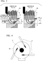
FIG. 3 is a diagram showing an arrangement of theburner 5 and thelance 6 provided on thefurnace wall 2A of the electric furnace 1. The installation position of thelance 6 on thefurnace wall 2A is above the installation position of theburner 5. That is, when the height position of the burner 5 (the distance between the tip surface of the burner and the surface of the molten metal) is L1, and the height position of the lance 6 (the distance between the tip surface of the lance and the surface of the molten metal) is L2, theburner 5 and thelance 6 are installed so that L1 < L2 (the left diagram inFIG. 3 ). Here, the surface of the molten metal means the upper surface of the molten metal formed by molten steel obtained by melting the cold iron source. - When the angle formed by a center axis of the
burner 5 and the horizontal direction is α, theburner 5 is fixed so that 90° > α > 0° (right diagram inFIG. 3 ). More preferably, 60° < α < 45°. Further, when an angle formed by a center axis of thelance 6 and the horizontal direction is β, thelance 6 is fixed so that α ≥ β ≥ 0° (right diagram inFIG. 3 ). That is, the ejection direction of the oxidant gas from thelance 6 is a direction having an angle equal to or greater than the angle formed by the direction in which the flame is formed by theburner 5 with respect to the horizontal direction. By setting the direction of thelance 6 in this way, the unburned gas (mainly carbon monoxide and hydrogen) when theburner 5 is burned can be efficiently combusted by the oxidant gas from thelance 6. -
FIG. 4 is a diagram showing the arrangement of theburners 5 from the upper part of the electric furnace 1.FIG. 4 shows an example in which threeburners 5 are installed. The flame of theburner 5 is directed toward a vicinity of the center between thefurnace wall 2A and theelectrodes 4 at which the cold iron source is not sufficiently heated. In order not to damage theelectrode 4, it is desirable to install theburner 5 so that the flame does not directly contact theelectrode 4. -
FIG. 5 is a schematic cross-sectional diagram showing the configuration of theburner 5 in the present embodiment. Theburner 5 shown inFIG. 5 is a burner having a lance function (burner lance). An oxidantgas supply pipe 18 for supplying the oxidant gas containing oxygen is provided at the center of theoxygen burner lance 5 in the present embodiment, and a fuelfluid supply pipe 19 for supplying a fuel fluid is provided on the outer periphery of the oxidantgas supply pipe 18. In addition, an oxidantgas supply pipe 20 is provided concentrically on the outer periphery of the fuelfluid supply pipe 19. A reflux typewater cooling jacket 21 is provided on the outer periphery of the combustion-supportingfluid supply pipe 20. - Note that the oxidant
gas supply pipe 20 may not be provided, and the refluxwater cooling jacket 21 may be provided on the outer periphery of the fuelfluid supply pipe 19. When the oxidantgas supply pipe 20 is provided, the flame length can be adjusted by adjusting the oxygen flow rate ratio between the oxidantgas supply pipes 18 and the oxidantgas supply pipes 20. - The oxidant
gas supply pipe 18 includes alarge diameter portion 18a having a constant inner diameter, athroat portion 18b having an inner diameter smaller than that of thelarge diameter portion 18a, a widenedportion 18c having an inner diameter that gradually increases from thethroat portion 18b toward thedistal end side 18B, and alinear motion portion 18d having a substantially constant inner diameter from theproximal side 18A to thedistal side 18B. - As described above, the oxidant
gas supply hole 6A for installing thelance 6 which introduces the oxidant gas containing oxygen for secondary combustion into the furnace is provided above thefurnace wall 2A at which the burner lance (burner 5) is installed. - It is desirable to provide a reflux type water cooling jacket in the oxidant
gas supply hole 6A which supplies the oxidant gas containing oxygen. When the water cooling jacket is provided around thelance 6, thelance 6 can be installed regardless of whether the furnace wall is a refractory wall or a water-cooled wall. -
FIG. 6 shows a configuration of the oxygen flow rate adjusting mechanism for supplying oxygen to thelance 6. The oxygen flow rate adjusting mechanism includes apressure control valve 10, apressure gauge 11, aflow rate controller 12, and a flowrate control valve 13 from the oxygen supply side. - A method for melting/refining the cold iron source using the melting/refining furnace 1 will be described.
- First, as shown in
FIG. 2 , the cold iron source is supplied from the upper opening of thefurnace body 2 from which theelectrode 4 and thefurnace lid 3 are removed (first step). - Next, the
electrode 4 is lowered to a predetermined position in the center of the melting/refining furnace 1, and the upper portion of thefurnace body 2 is covered with thefurnace lid 3. Then, theelectrode 4 is energized to melt the cold iron source (second step). - When melting of the cold iron source begins and the molten metal begins to accumulate in the
furnace bottom 2B, the cold iron source is auxiliary melted by a plurality ofburners 5 provided on thefurnace wall 2A of the melting/refining furnace 1 (third step). - Then, at the same time as the start of the third step or immediately after the third step, oxygen is ejected from the
lance 6 installed in the oxidantgas supply hole 6A provided in thefurnace wall 2A, and the oxygen is reacted with carbon monoxide, hydrogen, or a mixture of carbon monoxide and hydrogen generated during melting of the cold iron source (fourth step). - From the first step to the fourth step is the melting step.
- The amount of oxygen supplied from the
lance 6 in the fourth step can be determined from the volume of the melting/refining furnace 1. That is, when the volume of the melting/refining furnace 1 is V (m3), and the amount of oxygen introduced in the fourth step is Q (Nm3/h), V/Q is adjusted in a range from 0.1 to 0.8. Here, the volume V of the furnace is the internal volume of thefurnace body 2 before the cold iron source is charged. - When the cold iron source is almost melted in the melting step and the molten steel melted at the bottom of the furnace accumulates as molten metal, the fuel supply to the burner lance (burner 5) is stopped and switched to lance mode to introduce oxygen into the molten metal, and thereby impurities are removed. This is the refining step.
- Using the melting/refining furnace having the internal volume of the furnace body is VI (m3), the melting step (first step to fourth step) was performed. An exhaust gas analyzer and an exhaust gas flow rate measuring device (not shown in figures) were installed at the exhaust gas outlet of the melting/refining furnace so that the amount of carbon monoxide (CO) and hydrogen (H2) in the exhaust gas can be measured when oxygen gas is introduced into the furnace from the lance in the third step.
- In the third step, the amount Q (Nm3/h) of oxygen introduced into the furnace from the
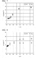
lance 6 was changed using the oxygen flow rate adjusting mechanism, and the amount of carbon monoxide and hydrogen in the exhaust gas from the melting/refining furnace was measured. The results are shown inFIG. 7 . - The horizontal axis of
FIG. 7 is V1/Q. The vertical axis is the amount (Nm3/t) of carbon monoxide and hydrogen (CO, H2) generated per 1 t of an iron obtained by melting the cold iron source. - It was confirmed that when V1/Q was in a range from 0.1 to 0.8, the amount of CO and H2 generated decreased as the amount of the oxygen introduced increased. However, when V1/Q was more than 0.8, the concentrations of CO and H2 hardly changed. That is, it was understood that the amount of the oxygen introduced was insufficient, and that secondary combustion was not sufficiently performed. It was also confirmed that when V1/Q was less than 0.1 or more, even when the amount of the oxygen introduced was increased below 0.1, there was no significant change in the amount of CO and H2 generated.
- A similar test was performed using the other melting/refining furnace (inner volume of the furnace body is V2). The results are shown in
FIG. 8 . When V2/Q was in a range from 0.1 to 0.8, an effect of reducing carbon monoxide and hydrogen according to the amount of oxygen introduced from thelance 6 was observed. That is, an appropriate amount of oxygen introduced without waste is when V2/Q is in the range of 0.1 to 0.8. - The method of operating a melting/refining furnace and the melting/refining furnace of the present invention can be used for melting a cold iron source in an electric furnace.
-
- 1
- melting/refining furnace (electric furnace)
- 2
- furnace body
- 2A
- furnace wall
- 2B
- furnace bottom
- 3
- furnace lid
- 4
- electrode
- 5
- burner (burner lance)
- 5A
- through hole
- 6
- lance
- 6A
- oxidant gas supply hole
- 10
- pressure control valve
- 11
- pressure gauge
- 12
- flow rate controller
- 13
- flow rate control valve
- 18
- oxidant gas supply pipe
- 19
- fuel fluid supply pipe
- 20
- oxidant gas supply pipe
- 21
- reflux water cooling jacket
Claims (3)
- A method for melting/refining a cold iron source using a melting/refining furnace, wherein the method comprises:a refining step comprising:a first step in which a cold iron source is supplied from an upper part of the melting/refining furnace;a second step in which the cold iron source is mainly melted by energizing an electrode provided in a center of the melting/refining furnace;a third step in which the cold iron source is auxiliary melted by a burner provided on a furnace wall of the melting/refining furnace; anda fourth step in which an oxidant gas is ejected from a lance installed in an oxidant gas ejection hole provided in the furnace wall above the burner downward from the horizontal direction, the oxidant gas is reacted with carbon monoxide, hydrogen, or a mixture of carbon monoxide and hydrogen which are generated during melting of the cold iron source; anda refining step in which impurities are removed by introducing oxygen into the molten iron generated by melting the cold iron source;the fourth step starts at the same time as or immediately after the start of the third step, and ends with the start of the refining step,when a volume of the furnace is V (m3) and an amount of oxygen introduced in the fourth step is Q (Nm3/h), V/Q is in a range from 0.1 to 0.8.
- A melting/refining furnace for a cold iron source comprising:the melting/refining furnace is an electric furnace having an opening for introducing a cold iron source in the upper part,the electric furnace comprises:an electrode which is provided in the center of the electric furnace and configured to melt the cold iron source;a burner which is provided on the furnace wall and configured to auxiliary melt the cold iron source;a lance which is provided on the furnace wall above the burner and is configured to introduce oxygen; andan oxygen flow rate adjustment mechanism which is configured to supply a certain amount of oxygen to the lance,an install position of the burner and the lance on the furnace wall satisfies the following conditions:when a distance from a surface of a molten metal to a tip surface of the burner is L1, and a distance from the surface of the molten metal to the tip surface of the lance is L2, L1 < L2;when an angle between a center axis of the burner and a horizontal plane is α, and an angle between a center axis of the lance and the horizontal plane is β,α ≥ β;90° > α > 0°; andβ ≥ 0°
- The melting/refining furnace for a cold iron source according to Claim 2, wherein ane oxygen flow rate adjusting mechanism comprises a flow rate control valve, a flow rate indicator, a pressure gauge, and a pressure control valve.
Applications Claiming Priority (1)
| Application Number | Priority Date | Filing Date | Title |
|---|---|---|---|
| PCT/JP2017/035235 WO2019064433A1 (en) | 2017-09-28 | 2017-09-28 | Method for adjusting melting-refining furnace and melting-refining furnace |
Publications (2)
| Publication Number | Publication Date |
|---|---|
| EP3690066A1 true EP3690066A1 (en) | 2020-08-05 |
| EP3690066A4 EP3690066A4 (en) | 2021-03-31 |
Family
ID=65901089
Family Applications (1)
| Application Number | Title | Priority Date | Filing Date |
|---|---|---|---|
| EP17927214.1A Pending EP3690066A4 (en) | 2017-09-28 | 2017-09-28 | ADJUSTMENT PROCEDURE FOR A FUSION-REFINING OVEN AND FUSION-REFINING OVEN |
Country Status (6)
| Country | Link |
|---|---|
| US (1) | US20200165692A1 (en) |
| EP (1) | EP3690066A4 (en) |
| JP (1) | JPWO2019064433A1 (en) |
| CN (1) | CN111094597A (en) |
| MY (1) | MY199365A (en) |
| WO (1) | WO2019064433A1 (en) |
Families Citing this family (2)
| Publication number | Priority date | Publication date | Assignee | Title |
|---|---|---|---|---|
| JP6427829B2 (en) * | 2016-03-31 | 2018-11-28 | 大陽日酸株式会社 | Cold iron source melting / smelting furnace, and melting / smelting furnace operating method |
| EP4273274A4 (en) * | 2021-02-10 | 2024-08-14 | JFE Steel Corporation | BURNER WITH IMAGING DEVICE, ELECTRIC FURNACE EQUIPPED WITH SAID BURNER AND METHOD FOR MANUFACTURING MOLTEN IRON USING SAID ELECTRIC FURNACE |
Family Cites Families (17)
| Publication number | Priority date | Publication date | Assignee | Title |
|---|---|---|---|---|
| JPS591982A (en) * | 1982-06-28 | 1984-01-07 | 大同特殊鋼株式会社 | Arc furnace melting method |
| US4923391A (en) * | 1984-08-17 | 1990-05-08 | American Combustion, Inc. | Regenerative burner |
| GB8516143D0 (en) * | 1985-06-26 | 1985-07-31 | British Steel Corp | Melting of metals |
| JPH05271811A (en) * | 1992-03-30 | 1993-10-19 | Nippon Sanso Kk | Method for melting metal |
| JPH07145420A (en) * | 1993-09-30 | 1995-06-06 | Ishikawajima Harima Heavy Ind Co Ltd | Electric arc melting furnace |
| EP0784193B1 (en) * | 1995-08-08 | 2002-07-03 | Nippon Sanso Corporation | Metal fusion furnace and metal fusing method |
| AT404942B (en) * | 1997-06-27 | 1999-03-25 | Voest Alpine Ind Anlagen | PLANT AND METHOD FOR PRODUCING METAL MELT |
| JPH11293326A (en) * | 1998-04-09 | 1999-10-26 | Daido Steel Co Ltd | Electric arc furnace operation method |
| FR2793263A1 (en) * | 1999-05-07 | 2000-11-10 | Air Liquide | ELECTRIC ARC FURNACE FOR THE PRODUCTION OF STEEL AND METHOD FOR IMPLEMENTING SAME |
| JP2000337776A (en) | 1999-05-25 | 2000-12-08 | Nkk Corp | Method of improving secondary combustion rate and heat transfer efficiency in melting furnace, etc. |
| JP2001262216A (en) * | 2000-03-23 | 2001-09-26 | Nkk Corp | Dissolution method of iron scrap |
| JP4050195B2 (en) | 2002-07-08 | 2008-02-20 | 大陽日酸株式会社 | Method of melting and refining furnace for refrigerating iron source and refining method |
| US7858022B2 (en) * | 2005-06-09 | 2010-12-28 | Nippon Crucible Co., Ltd. | Crucible-type continuous melting furnace |
| JP5068493B2 (en) * | 2006-08-10 | 2012-11-07 | 大陽日酸株式会社 | Combustion method of burner and powder combustible material, and melting and refining method of cold iron source |
| EP2080972A1 (en) * | 2008-01-08 | 2009-07-22 | L'AIR LIQUIDE, Société Anonyme pour l'Etude et l'Exploitation des Procédés Georges Claude | Combined burner and lance apparatus for electric arc furnaces |
| CN102443678B (en) * | 2011-12-27 | 2013-11-27 | 攀钢集团江油长城特殊钢有限公司 | Method for smelting stainless steel mother liquor with furnace wall carbon-oxygen spray gun in arc furnace |
| JP6036172B2 (en) * | 2012-03-29 | 2016-11-30 | Jfeスチール株式会社 | Method of refining hot metal in converter |
-
2017
- 2017-09-28 MY MYPI2020001043A patent/MY199365A/en unknown
- 2017-09-28 JP JP2019545494A patent/JPWO2019064433A1/en not_active Withdrawn
- 2017-09-28 WO PCT/JP2017/035235 patent/WO2019064433A1/en not_active Ceased
- 2017-09-28 EP EP17927214.1A patent/EP3690066A4/en active Pending
- 2017-09-28 US US16/638,530 patent/US20200165692A1/en not_active Abandoned
- 2017-09-28 CN CN201780094881.XA patent/CN111094597A/en active Pending
Also Published As
| Publication number | Publication date |
|---|---|
| US20200165692A1 (en) | 2020-05-28 |
| CN111094597A (en) | 2020-05-01 |
| EP3690066A4 (en) | 2021-03-31 |
| MY199365A (en) | 2023-10-24 |
| JPWO2019064433A1 (en) | 2020-03-26 |
| WO2019064433A1 (en) | 2019-04-04 |
Similar Documents
| Publication | Publication Date | Title |
|---|---|---|
| US6296479B1 (en) | Direct reduction method and rotary hearth furnace | |
| RU2494324C2 (en) | Combined burner and tuyere for electric arc furnaces | |
| ITUD950003A1 (en) | MELTING PROCEDURE FOR ELECTRIC ARC OVEN WITH ALTERNATIVE ENERGY SOURCES AND RELATED ELECTRIC ARC OVEN | |
| EP0965649A1 (en) | Supersonic coherent gas jet for providing gas into a liquid | |
| KR101616212B1 (en) | Lances for top submerged injection | |
| KR101728286B1 (en) | Exhaust gas treatment method and exhaust gas treatment device | |
| JP2001192717A5 (en) | ||
| JP2008179876A (en) | Powder heating burner lance and smelting reduction method using the same | |
| US11053559B2 (en) | Melting and refining furnace for cold iron source and method of operating melting and refining furnace | |
| US20200165692A1 (en) | Method for operating melting/refining furnace and melting-refining furnace | |
| EP4144869A1 (en) | Melting/refining furnace for cold iron sources, and melting/refining furnace operation method | |
| KR960016161B1 (en) | Process & device for the disposal of dust in a cupola by combustion/slag production | |
| JP4050195B2 (en) | Method of melting and refining furnace for refrigerating iron source and refining method | |
| US20040174920A1 (en) | Method and apparatus for spatial energy coverage | |
| TWI817466B (en) | Electric furnaces and steelmaking methods | |
| TWI735668B (en) | Method for operating melting/refining furnace and melting/refining furnace | |
| EP4653554A1 (en) | Molten-iron production method | |
| JP6393291B2 (en) | Melting / smelting furnace operation method and melting / smelting furnace | |
| JP4119336B2 (en) | Method for melting and refining porous burners and lances and cold iron sources | |
| CN114616349A (en) | Method for manufacturing molten iron based on electric furnace | |
| HUE035556T2 (en) | Device and method for electro-slag remelting | |
| JP2013533950A (en) | Method and system for removing deposits formed in a furnace | |
| US8741226B2 (en) | Reduction-oxidation furnace for making phosphorus by thermal process | |
| CN218002209U (en) | Melting furnace | |
| JP4223604B2 (en) | Auxiliary burner equipment for metal melting furnaces |
Legal Events
| Date | Code | Title | Description |
|---|---|---|---|
| STAA | Information on the status of an ep patent application or granted ep patent |
Free format text: STATUS: THE INTERNATIONAL PUBLICATION HAS BEEN MADE |
|
| PUAI | Public reference made under article 153(3) epc to a published international application that has entered the european phase |
Free format text: ORIGINAL CODE: 0009012 |
|
| STAA | Information on the status of an ep patent application or granted ep patent |
Free format text: STATUS: REQUEST FOR EXAMINATION WAS MADE |
|
| 17P | Request for examination filed |
Effective date: 20200225 |
|
| AK | Designated contracting states |
Kind code of ref document: A1 Designated state(s): AL AT BE BG CH CY CZ DE DK EE ES FI FR GB GR HR HU IE IS IT LI LT LU LV MC MK MT NL NO PL PT RO RS SE SI SK SM TR |
|
| AX | Request for extension of the european patent |
Extension state: BA ME |
|
| DAV | Request for validation of the european patent (deleted) | ||
| DAX | Request for extension of the european patent (deleted) | ||
| A4 | Supplementary search report drawn up and despatched |
Effective date: 20210301 |
|
| RIC1 | Information provided on ipc code assigned before grant |
Ipc: C21C 5/52 20060101AFI20210223BHEP Ipc: C21B 13/12 20060101ALI20210223BHEP Ipc: F27B 3/08 20060101ALI20210223BHEP Ipc: F27D 3/16 20060101ALI20210223BHEP Ipc: F27B 3/22 20060101ALI20210223BHEP Ipc: F27D 3/00 20060101ALI20210223BHEP Ipc: F27D 19/00 20060101ALI20210223BHEP Ipc: F27D 99/00 20100101ALI20210223BHEP Ipc: F27B 3/20 20060101ALI20210223BHEP Ipc: C21C 5/46 20060101ALI20210223BHEP |
|
| STAA | Information on the status of an ep patent application or granted ep patent |
Free format text: STATUS: EXAMINATION IS IN PROGRESS |
|
| 17Q | First examination report despatched |
Effective date: 20220111 |