EP3690017A1 - Image analysis device, method, and program - Google Patents
Image analysis device, method, and program Download PDFInfo
- Publication number
- EP3690017A1 EP3690017A1 EP18861728.6A EP18861728A EP3690017A1 EP 3690017 A1 EP3690017 A1 EP 3690017A1 EP 18861728 A EP18861728 A EP 18861728A EP 3690017 A1 EP3690017 A1 EP 3690017A1
- Authority
- EP
- European Patent Office
- Prior art keywords
- region
- image
- contour
- cells
- fluorescence image
- Prior art date
- Legal status (The legal status is an assumption and is not a legal conclusion. Google has not performed a legal analysis and makes no representation as to the accuracy of the status listed.)
- Granted
Links
- 0 CCCCC([C@](C)*)=NC Chemical compound CCCCC([C@](C)*)=NC 0.000 description 1
Images



Classifications
-
- G—PHYSICS
- G06—COMPUTING OR CALCULATING; COUNTING
- G06T—IMAGE DATA PROCESSING OR GENERATION, IN GENERAL
- G06T7/00—Image analysis
- G06T7/10—Segmentation; Edge detection
- G06T7/11—Region-based segmentation
-
- G—PHYSICS
- G06—COMPUTING OR CALCULATING; COUNTING
- G06T—IMAGE DATA PROCESSING OR GENERATION, IN GENERAL
- G06T7/00—Image analysis
- G06T7/0002—Inspection of images, e.g. flaw detection
- G06T7/0012—Biomedical image inspection
-
- C—CHEMISTRY; METALLURGY
- C12—BIOCHEMISTRY; BEER; SPIRITS; WINE; VINEGAR; MICROBIOLOGY; ENZYMOLOGY; MUTATION OR GENETIC ENGINEERING
- C12M—APPARATUS FOR ENZYMOLOGY OR MICROBIOLOGY; APPARATUS FOR CULTURING MICROORGANISMS FOR PRODUCING BIOMASS, FOR GROWING CELLS OR FOR OBTAINING FERMENTATION OR METABOLIC PRODUCTS, i.e. BIOREACTORS OR FERMENTERS
- C12M23/00—Constructional details, e.g. recesses, hinges
- C12M23/02—Form or structure of the vessel
- C12M23/10—Petri dish
-
- C—CHEMISTRY; METALLURGY
- C12—BIOCHEMISTRY; BEER; SPIRITS; WINE; VINEGAR; MICROBIOLOGY; ENZYMOLOGY; MUTATION OR GENETIC ENGINEERING
- C12M—APPARATUS FOR ENZYMOLOGY OR MICROBIOLOGY; APPARATUS FOR CULTURING MICROORGANISMS FOR PRODUCING BIOMASS, FOR GROWING CELLS OR FOR OBTAINING FERMENTATION OR METABOLIC PRODUCTS, i.e. BIOREACTORS OR FERMENTERS
- C12M23/00—Constructional details, e.g. recesses, hinges
- C12M23/02—Form or structure of the vessel
- C12M23/12—Well or multiwell plates
-
- G—PHYSICS
- G01—MEASURING; TESTING
- G01N—INVESTIGATING OR ANALYSING MATERIALS BY DETERMINING THEIR CHEMICAL OR PHYSICAL PROPERTIES
- G01N21/00—Investigating or analysing materials by the use of optical means, i.e. using sub-millimetre waves, infrared, visible or ultraviolet light
- G01N21/62—Systems in which the material investigated is excited whereby it emits light or causes a change in wavelength of the incident light
- G01N21/63—Systems in which the material investigated is excited whereby it emits light or causes a change in wavelength of the incident light optically excited
- G01N21/64—Fluorescence; Phosphorescence
-
- G—PHYSICS
- G02—OPTICS
- G02B—OPTICAL ELEMENTS, SYSTEMS OR APPARATUS
- G02B21/00—Microscopes
- G02B21/16—Microscopes adapted for ultraviolet illumination ; Fluorescence microscopes
-
- G—PHYSICS
- G02—OPTICS
- G02B—OPTICAL ELEMENTS, SYSTEMS OR APPARATUS
- G02B21/00—Microscopes
- G02B21/36—Microscopes arranged for photographic purposes or projection purposes or digital imaging or video purposes including associated control and data processing arrangements
-
- G—PHYSICS
- G02—OPTICS
- G02B—OPTICAL ELEMENTS, SYSTEMS OR APPARATUS
- G02B21/00—Microscopes
- G02B21/36—Microscopes arranged for photographic purposes or projection purposes or digital imaging or video purposes including associated control and data processing arrangements
- G02B21/365—Control or image processing arrangements for digital or video microscopes
-
- G—PHYSICS
- G02—OPTICS
- G02B—OPTICAL ELEMENTS, SYSTEMS OR APPARATUS
- G02B21/00—Microscopes
- G02B21/36—Microscopes arranged for photographic purposes or projection purposes or digital imaging or video purposes including associated control and data processing arrangements
- G02B21/365—Control or image processing arrangements for digital or video microscopes
- G02B21/367—Control or image processing arrangements for digital or video microscopes providing an output produced by processing a plurality of individual source images, e.g. image tiling, montage, composite images, depth sectioning, image comparison
-
- G—PHYSICS
- G06—COMPUTING OR CALCULATING; COUNTING
- G06F—ELECTRIC DIGITAL DATA PROCESSING
- G06F18/00—Pattern recognition
- G06F18/20—Analysing
- G06F18/25—Fusion techniques
- G06F18/251—Fusion techniques of input or preprocessed data
-
- G—PHYSICS
- G06—COMPUTING OR CALCULATING; COUNTING
- G06F—ELECTRIC DIGITAL DATA PROCESSING
- G06F18/00—Pattern recognition
- G06F18/20—Analysing
- G06F18/25—Fusion techniques
- G06F18/253—Fusion techniques of extracted features
-
- G—PHYSICS
- G06—COMPUTING OR CALCULATING; COUNTING
- G06T—IMAGE DATA PROCESSING OR GENERATION, IN GENERAL
- G06T7/00—Image analysis
- G06T7/10—Segmentation; Edge detection
- G06T7/13—Edge detection
-
- G—PHYSICS
- G06—COMPUTING OR CALCULATING; COUNTING
- G06T—IMAGE DATA PROCESSING OR GENERATION, IN GENERAL
- G06T7/00—Image analysis
- G06T7/10—Segmentation; Edge detection
- G06T7/174—Segmentation; Edge detection involving the use of two or more images
-
- G—PHYSICS
- G06—COMPUTING OR CALCULATING; COUNTING
- G06T—IMAGE DATA PROCESSING OR GENERATION, IN GENERAL
- G06T7/00—Image analysis
- G06T7/60—Analysis of geometric attributes
-
- G—PHYSICS
- G06—COMPUTING OR CALCULATING; COUNTING
- G06V—IMAGE OR VIDEO RECOGNITION OR UNDERSTANDING
- G06V10/00—Arrangements for image or video recognition or understanding
- G06V10/40—Extraction of image or video features
- G06V10/46—Descriptors for shape, contour or point-related descriptors, e.g. scale invariant feature transform [SIFT] or bags of words [BoW]; Salient regional features
-
- G—PHYSICS
- G06—COMPUTING OR CALCULATING; COUNTING
- G06V—IMAGE OR VIDEO RECOGNITION OR UNDERSTANDING
- G06V10/00—Arrangements for image or video recognition or understanding
- G06V10/70—Arrangements for image or video recognition or understanding using pattern recognition or machine learning
- G06V10/77—Processing image or video features in feature spaces; using data integration or data reduction, e.g. principal component analysis [PCA] or independent component analysis [ICA] or self-organising maps [SOM]; Blind source separation
- G06V10/80—Fusion, i.e. combining data from various sources at the sensor level, preprocessing level, feature extraction level or classification level
- G06V10/806—Fusion, i.e. combining data from various sources at the sensor level, preprocessing level, feature extraction level or classification level of extracted features
-
- G—PHYSICS
- G06—COMPUTING OR CALCULATING; COUNTING
- G06V—IMAGE OR VIDEO RECOGNITION OR UNDERSTANDING
- G06V20/00—Scenes; Scene-specific elements
- G06V20/60—Type of objects
- G06V20/69—Microscopic objects, e.g. biological cells or cellular parts
- G06V20/695—Preprocessing, e.g. image segmentation
-
- G—PHYSICS
- G06—COMPUTING OR CALCULATING; COUNTING
- G06V—IMAGE OR VIDEO RECOGNITION OR UNDERSTANDING
- G06V20/00—Scenes; Scene-specific elements
- G06V20/60—Type of objects
- G06V20/69—Microscopic objects, e.g. biological cells or cellular parts
- G06V20/698—Matching; Classification
-
- C—CHEMISTRY; METALLURGY
- C12—BIOCHEMISTRY; BEER; SPIRITS; WINE; VINEGAR; MICROBIOLOGY; ENZYMOLOGY; MUTATION OR GENETIC ENGINEERING
- C12M—APPARATUS FOR ENZYMOLOGY OR MICROBIOLOGY; APPARATUS FOR CULTURING MICROORGANISMS FOR PRODUCING BIOMASS, FOR GROWING CELLS OR FOR OBTAINING FERMENTATION OR METABOLIC PRODUCTS, i.e. BIOREACTORS OR FERMENTERS
- C12M41/00—Means for regulation, monitoring, measurement or control, e.g. flow regulation
- C12M41/30—Means for regulation, monitoring, measurement or control, e.g. flow regulation of concentration
- C12M41/36—Means for regulation, monitoring, measurement or control, e.g. flow regulation of concentration of biomass, e.g. colony counters or by turbidity measurements
-
- G—PHYSICS
- G01—MEASURING; TESTING
- G01N—INVESTIGATING OR ANALYSING MATERIALS BY DETERMINING THEIR CHEMICAL OR PHYSICAL PROPERTIES
- G01N21/00—Investigating or analysing materials by the use of optical means, i.e. using sub-millimetre waves, infrared, visible or ultraviolet light
- G01N21/62—Systems in which the material investigated is excited whereby it emits light or causes a change in wavelength of the incident light
- G01N21/63—Systems in which the material investigated is excited whereby it emits light or causes a change in wavelength of the incident light optically excited
- G01N21/64—Fluorescence; Phosphorescence
- G01N21/6428—Measuring fluorescence of fluorescent products of reactions or of fluorochrome labelled reactive substances, e.g. measuring quenching effects, using measuring "optrodes"
- G01N2021/6439—Measuring fluorescence of fluorescent products of reactions or of fluorochrome labelled reactive substances, e.g. measuring quenching effects, using measuring "optrodes" with indicators, stains, dyes, tags, labels, marks
- G01N2021/6441—Measuring fluorescence of fluorescent products of reactions or of fluorochrome labelled reactive substances, e.g. measuring quenching effects, using measuring "optrodes" with indicators, stains, dyes, tags, labels, marks with two or more labels
-
- G—PHYSICS
- G01—MEASURING; TESTING
- G01N—INVESTIGATING OR ANALYSING MATERIALS BY DETERMINING THEIR CHEMICAL OR PHYSICAL PROPERTIES
- G01N21/00—Investigating or analysing materials by the use of optical means, i.e. using sub-millimetre waves, infrared, visible or ultraviolet light
- G01N21/62—Systems in which the material investigated is excited whereby it emits light or causes a change in wavelength of the incident light
- G01N21/63—Systems in which the material investigated is excited whereby it emits light or causes a change in wavelength of the incident light optically excited
- G01N21/64—Fluorescence; Phosphorescence
- G01N21/645—Specially adapted constructive features of fluorimeters
- G01N21/6456—Spatial resolved fluorescence measurements; Imaging
- G01N21/6458—Fluorescence microscopy
-
- G—PHYSICS
- G02—OPTICS
- G02B—OPTICAL ELEMENTS, SYSTEMS OR APPARATUS
- G02B2207/00—Coding scheme for general features or characteristics of optical elements and systems of subclass G02B, but not including elements and systems which would be classified in G02B6/00 and subgroups
- G02B2207/113—Fluorescence
-
- G—PHYSICS
- G06—COMPUTING OR CALCULATING; COUNTING
- G06T—IMAGE DATA PROCESSING OR GENERATION, IN GENERAL
- G06T2207/00—Indexing scheme for image analysis or image enhancement
- G06T2207/10—Image acquisition modality
- G06T2207/10024—Color image
-
- G—PHYSICS
- G06—COMPUTING OR CALCULATING; COUNTING
- G06T—IMAGE DATA PROCESSING OR GENERATION, IN GENERAL
- G06T2207/00—Indexing scheme for image analysis or image enhancement
- G06T2207/10—Image acquisition modality
- G06T2207/10056—Microscopic image
-
- G—PHYSICS
- G06—COMPUTING OR CALCULATING; COUNTING
- G06T—IMAGE DATA PROCESSING OR GENERATION, IN GENERAL
- G06T2207/00—Indexing scheme for image analysis or image enhancement
- G06T2207/10—Image acquisition modality
- G06T2207/10056—Microscopic image
- G06T2207/10061—Microscopic image from scanning electron microscope
-
- G—PHYSICS
- G06—COMPUTING OR CALCULATING; COUNTING
- G06T—IMAGE DATA PROCESSING OR GENERATION, IN GENERAL
- G06T2207/00—Indexing scheme for image analysis or image enhancement
- G06T2207/10—Image acquisition modality
- G06T2207/10064—Fluorescence image
-
- G—PHYSICS
- G06—COMPUTING OR CALCULATING; COUNTING
- G06T—IMAGE DATA PROCESSING OR GENERATION, IN GENERAL
- G06T2207/00—Indexing scheme for image analysis or image enhancement
- G06T2207/30—Subject of image; Context of image processing
- G06T2207/30004—Biomedical image processing
- G06T2207/30024—Cell structures in vitro; Tissue sections in vitro
Definitions
- the display device 30 displays, for example, the first fluorescence image K1, the second fluorescence image K2, and the superimposed image K0 in response to a command from the display control unit 24 and comprises, for example, a liquid crystal display.
- the display device 30 may be configured by a touch panel and may also be used as the input device 40.
- the similarity S(P1) between the contour of the first region A1 and the contour of the second region A2 is calculated by the following Expression (1).
- S P 1 w 1 ⁇ n ⁇ 1 ⁇ n ⁇ 2 ⁇ + w 2 1 1 + d
- w1 and w2 are weight coefficients.
- the first determination unit 22 determines whether or not the similarity S(P1) is equal to or greater than a predetermined threshold value Th2. In a case in which the similarity S(P1) is equal to or greater than the threshold value Th2, the first determination unit 22 determines that the first region A1 is included in the second region A2 with respect to the set first reference point PI.
Landscapes
- Engineering & Computer Science (AREA)
- Physics & Mathematics (AREA)
- General Physics & Mathematics (AREA)
- Theoretical Computer Science (AREA)
- Health & Medical Sciences (AREA)
- Computer Vision & Pattern Recognition (AREA)
- Multimedia (AREA)
- Chemical & Material Sciences (AREA)
- Life Sciences & Earth Sciences (AREA)
- General Health & Medical Sciences (AREA)
- Analytical Chemistry (AREA)
- Bioinformatics & Cheminformatics (AREA)
- Biomedical Technology (AREA)
- Optics & Photonics (AREA)
- Wood Science & Technology (AREA)
- Biochemistry (AREA)
- Zoology (AREA)
- Organic Chemistry (AREA)
- Nuclear Medicine, Radiotherapy & Molecular Imaging (AREA)
- General Engineering & Computer Science (AREA)
- Medical Informatics (AREA)
- Evolutionary Computation (AREA)
- Data Mining & Analysis (AREA)
- Artificial Intelligence (AREA)
- Molecular Biology (AREA)
- Biotechnology (AREA)
- Clinical Laboratory Science (AREA)
- Genetics & Genomics (AREA)
- Sustainable Development (AREA)
- Microbiology (AREA)
- Immunology (AREA)
- Pathology (AREA)
- Software Systems (AREA)
- Computing Systems (AREA)
- Quality & Reliability (AREA)
- Radiology & Medical Imaging (AREA)
- Evolutionary Biology (AREA)
- Databases & Information Systems (AREA)
- Bioinformatics & Computational Biology (AREA)
- Geometry (AREA)
Abstract
An image acquisition unit 21 acquires a first fluorescence image indicating an observation target including a plurality of types of cells, each of which has a first region stained by first staining, and a second fluorescence image indicating the observation target in which a second region of a specific cell among the plurality of types of cells is stained by second staining different from the first staining. A first determination unit 22 determines whether or not the first region is included in the second region in a superimposed image obtained by superimposing the first fluorescence image and the second fluorescence image and acquires a first determination result for each of the first regions. A second determination unit 23 determines the type of cell included in the observation target on the basis of the first determination result.
Description
- The present invention relates to an image analysis apparatus, an image analysis method, and an image analysis program that analyze a fluorescence image of an observation target including a plurality of types of cells.
- In recent years, a method has been proposed which captures an image of pluripotent stem cells, such as embryonic stem (ES) cells and induced pluripotent stem (iPS) cells, or differentiation-induced cells with, for example, a microscope and checks the characteristics of the captured image to determine the differentiation state of the cells. Pluripotent stem cells, such as ES cells and iPS cells, have the ability to differentiate into cells of various tissues and attract attention as cells applicable to regenerative medicine, drug development, and disease elucidation.
- For example, in the fields of regenerative medicine and drug development, an image of cells stained with a fluorescent material is captured and the cells are examined on the basis of a fluorescence image acquired by imaging. Here, examples of the examination of the cells include the enumeration of cells having specific properties, such as undifferentiation, and the evaluation of the morphological characteristics of cells. The examination of the cells is performed by the observer's visual determination. However, in visual examination, there is a variation in the evaluation standard between the observers and the efficiency of examination is low. For this reason, automatic evaluation using an image analysis apparatus is performed.
- For example,
JP2009-122115A JP2006-018394A - However, the method described in
JP2009-122115A JP2006-018394A - The invention has been made in view of the above-mentioned problems and an object of the invention is to provide a technique that can determine the type of cell included in an observation target.
- According to the invention, there is provided an image analysis apparatus comprising: an image acquisition unit that acquires a first fluorescence image indicating an observation target including a plurality of types of cells, each of which has a first region stained by first staining, and a second fluorescence image indicating the observation target in which a second region of a specific cell among the plurality of types of cells is stained by second staining different from the first staining; a first determination unit that determines whether or not the first region is included in the second region in a superimposed image obtained by superimposing the first fluorescence image and the second fluorescence image and acquires a first determination result for each of the first regions; and a second determination unit that determines the type of cell included in the observation target on the basis of the first determination result.
- The "first region" is a region included in all of the plurality of types of cells. For example, a cell nucleus of each of the plurality of types of cells can be used as the first region.
- For the "second region", for example, the entire region in a cell membrane of a specific cell among the plurality of types of cells can be used as the second region.
- The "superimposed image" is an image obtained by superimposing the first fluorescence image and the second fluorescence image such that the corresponding pixels are matched with each other.
- In the image analysis apparatus according to the invention, among the plurality of types of cells, cells other than the specific cell may be negative for the second staining.
- The term "cell negative for the second staining" means that the cell is not stained by the second staining.
- In the image analysis apparatus according to the invention, the first determination unit may extract a contour of the second region from the second fluorescence image and acquire the first determination result on the basis of whether each of the first regions is located within the contour of the corresponding second region in the superimposed image.
- In this case, in a case in which it is difficult to acquire the first determination result, the first determination unit may acquire the first determination result on the basis of a percentage at which each of the first regions is located within the contour of the corresponding second region in the superimposed image.
- The contour may be extracted before the superimposed image is generated or after the superimposed image is generated.
- In the image analysis apparatus according to the invention, the first determination unit may extract a contour of the second region from the second fluorescence image and acquire the first determination result on the basis of a percentage at which each of the first regions is located within the contour of the corresponding second region in the superimposed image.
- In the image analysis apparatus according to the invention, the first determination unit may extract a contour of the first region from the first fluorescence image, extract a contour of the second region from the second fluorescence image, and acquire the first determination result on the basis of the contour of the first region and the contour of the second region in the superimposed image.
- In this case, the first determination unit may set a first reference point and a second reference point which are adjacent to each other on the contour of the first region and the contour of the second region in the superimposed image, respectively, and acquire the first determination result on the basis of first information indicating a contour direction of the first region at the first reference point, second information indicating a contour direction of the second region at the second reference point, and third information indicating a distance between the first reference point and the second reference point.
- According to the invention, there is provided an image analysis method comprising: acquiring a first fluorescence image indicating an observation target including a plurality of types of cells, each of which has a first region stained by first staining, and a second fluorescence image indicating the observation target in which a second region of a specific cell among the plurality of types of cells is stained by second staining different from the first staining; determining whether or not the first region is included in the second region in a superimposed image obtained by superimposing the first fluorescence image and the second fluorescence image and acquires a first determination result for each of the first regions; and determining the type of cell included in the observation target on the basis of the first determination result.
- In addition, a program that causes a computer to perform the image analysis method according to the invention may be provided.
- According to the invention, there is provided another image analysis apparatus comprising a memory that stores commands to be executed by a computer and a processor that is configured to execute the stored commands. The processor performs a process of acquiring a first fluorescence image indicating an observation target including a plurality of types of cells, each of which has a first region stained by first staining, and a second fluorescence image indicating the observation target in which a second region of a specific cell among the plurality of types of cells is stained by second staining different from the first staining, a process of determining whether or not the first region is included in the second region in a superimposed image obtained by superimposing the first fluorescence image and the second fluorescence image and acquires a first determination result for each of the first regions, and a process of determining the type of cell included in the observation target on the basis of the first determination result.
- According to the invention, in the superimposed image obtained by superimposing the first fluorescence image in the first region is stained by the first staining and the second fluorescence image in which the second region of a specific cell is stained by the second staining different from the first staining, it is determined whether or not the first region in the first fluorescence image is included in the second region in the second fluorescence image and the first determination result is acquired. Then, the type of cell included in the observation target is determined on the basis of the first determination result. Here, the first region of each of a plurality of types of cells is stained in the first fluorescence image and the second region of a specific cell is stained in the second fluorescence image. Therefore, for the specific cell, the second region and the first region overlap each other in the superimposed image and the first region is included in the second region. In contrast, since cells other than the specific cell are not stained by the second staining, the first region of the cell other than the specific cell is not included in the second region in the superimposed image. Therefore, according to the invention, it is possible to distinguish a specific type of cell from cells other than the specific type of cell included in the observation target. As a result, it is possible to determine the type of cell included in the observation target.
-
-
Fig. 1 is a block diagram schematically illustrating the configuration of an image analysis system using an image analysis apparatus according to an embodiment of the invention. -
Fig. 2 is a diagram illustrating a first fluorescence image. -
Fig. 3 is a diagram illustrating a second fluorescence image. -
Fig. 4 is a diagram illustrating a superimposed image. -
Fig. 5 is a diagram illustrating the inclusion of a first region in a second region. -
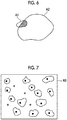
Fig. 6 is a diagram illustrating the calculation of a percentage at which the first region is located within the contour of the second region. -
Fig. 7 is a diagram illustrating a superimposed image in which a marker is given. -
Fig. 8 is a flowchart illustrating a process performed in this embodiment. -
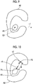
Fig. 9 is a diagram illustrating an example in which the first region is determined not to be included in the second region. -
Fig. 10 is a diagram illustrating the acquisition of a first determination result by another embodiment. - Hereinafter, an image analysis system using an embodiment of an image analysis apparatus according to the invention will be described in detail with reference to the drawings.
Fig. 1 is a block diagram schematically illustrating the configuration of the image analysis system according to this embodiment. As illustrated inFig. 1 , the image analysis system according to this embodiment comprises animaging apparatus 10, animage analysis apparatus 20, adisplay device 30, and aninput device 40. - First, in the image analysis system according to this embodiment, a biological sample including a plurality of types of cells is prepared as an observation target. Examples of the biological sample include pluripotent stem cells, such as cancer cells, iPS cells, and ES cells, nerve cells, skin cells, heart muscle cells, and liver cells differentiation-induced from stem cells, and skin cells, retina cells, heart muscle cells, blood cells, nerve cells, and organ cells extracted from the human body.
- In this embodiment, an example in which skin cells cultured using feeder cells are prepared as the biological sample and are evaluated will be described. In addition, the skin cell is a specific cell. Examples of the evaluation are the counting of the number of skin cells and the evaluation of the morphological characteristics of the skin cells. In addition, the skin cells are cultured in a container. The container may be, for example, a petri dish, a multi-well plate, or different wells of one multi-well plate. In this embodiment, first staining is performed for the biological sample to capture a first fluorescence image and then second staining is performed to acquire a second fluorescence image.
- A fluorescent material that stains the nuclei of all of the cells contained in the biological sample is used in the first staining. A fluorescent material for keratin staining which stains keratin of the skin cells contained in the biological sample is used in the second staining. Here, the feeder cells are negative for the keratin staining (second staining) and are not stained by the keratin staining. The creation and staining of the biological sample may be performed manually by the user or may be performed automatically using an apparatus including, for example, a mechanism for sucking cells and a robot arm.
- The
imaging apparatus 10 captures an image of the biological sample subjected to the first staining to acquire a first fluorescence image K1 and then captures an image of the biological sample subjected to the second staining to acquire a second fluorescence image K2. Specifically, a fluorescence microscope apparatus that comprises an imaging element, such as a charge-coupled device (CCD) image sensor or a complementary metal-oxide semiconductor (CMOS) image sensor, and detects the intensity of fluorescence emitted from the biological sample is used as theimaging apparatus 10. An imaging element that is provided with red, green, and blue (RGB) color filters or a monochrome imaging element may be used as the imaging element. The first fluorescence image K1 and the second fluorescence image K2 acquired by theimaging apparatus 10 are input to theimage analysis apparatus 20. - As illustrated in
Fig. 1 , theimage analysis apparatus 20 comprises animage acquisition unit 21, afirst determination unit 22, asecond determination unit 23, and adisplay control unit 24. Theimage analysis apparatus 20 is a computer comprising, for example, a central processing unit, a semiconductor memory, and a hard disk drive. An embodiment of an image analysis program according to the invention is installed in the hard disk drive. Then, the central processing unit executes the image analysis program such that theimage acquisition unit 21, thefirst determination unit 22, thesecond determination unit 23, and thedisplay control unit 24 illustrated inFig. 1 function. In this embodiment, the functions of each unit are implemented by the image analysis program. However, the invention is not limited thereto. For example, a plurality of integrated circuits (ICs), a processor, an application specific integrated circuit (ASIC), a field-programmable gate array (FPGA), and a memory may be appropriately combined to implement the functions of each unit. - The
image acquisition unit 21 acquires the first fluorescence image K1 and the second fluorescence image K2 output from theimaging apparatus 10 and stores the acquired images in a storage unit (not illustrated).Fig. 2 is a diagram illustrating the first fluorescence image andFig. 3 is a diagram illustrating the second fluorescence image. Here, since the nuclei of all of the cells included in the biological sample are stained by the first staining, all of the nuclei of the cells included in the biological sample are stained in the first fluorescence image K1. A region of the cell nucleus included in the first fluorescence image K1 is a first region A1. - In contrast, keratin of the skin cells included in the biological sample is stained by the second staining. Keratin is present in the cell membrane of the skin cell. Therefore, in the second fluorescence image K2, a region in the cell membrane of the skin cell included in the biological sample is stained. A region in the cell membrane of the skin cell included in the second fluorescence image K2 is a second region A2.
- Since a fluorescent material for the first staining is different from a fluorescent material for the second staining, the stained first region A1 in the first fluorescence image K1 and the stained second region A2 in the second fluorescence image K2 emit different fluorescent colors. In order to show this state, the stained first region A1 in the first fluorescence image K1 is blacked out in
Fig. 2 and the stained second region A2 in the second fluorescence image K2 is hatched inFig. 3 . - The
first determination unit 22 determines whether or not the first region A1 is included in the second region A2 and acquires a first determination result for each of the first regions A1. For this operation, thefirst determination unit 22 extracts the contour of the stained second region A2, that is, the region of the cell membrane of the skin cell from the second fluorescence image K2. For example, a method using a differential filter can be used as a method for extracting the contour. In addition, the contour may be extracted by a method that performs a binarization process for the second fluorescence image K2 to acquire a binarized image and traces a boundary line between the regions in the binarized image. Further, any method, such as adaptive binarization or Otsu's Binarization, may be used as the binarization process. - The
first determination unit 22 superimposes the second fluorescence image K2, from which the contour of the second region A2 has been extracted, and the first fluorescence image K1 to generate a superimposed image K0.Fig. 4 is a diagram illustrating the superimposed image generated in this embodiment. In the superimposed image K0 illustrated inFig. 4 , the filling of the first region A1 and an oblique line to the second region A2 are omitted. Thefirst determination unit 22 determines whether or not each of the first regions A1 is included in the corresponding second region A2 on the basis of whether or not each of the first regions A1 included in the superimposed image K0 is located within the contour of the second region A2 and acquires the first determination result. -
Fig. 5 is a diagram illustrating the inclusion of the first region in the second region. InFig. 5 , four first regions A11, A12, A13, and A14 and one second region A2 corresponding to the four first regions are illustrated. Thefirst determination unit 22 detects the centers of gravity G11, G12, G13, and G14 of the first regions A11, A12, A13, and A14. Then, thefirst determination unit 22 draws half lines L11, L12, L13, and L14 from the centers of gravity G11, G12, G13, and G14 in a predetermined direction in the superimposed image K0 and detects the number of intersection points between the half lines L11, L12, L13, and L14 and the contour of the second region A2. Then, thefirst determination unit 22 determines that the first region A1 is located within the contour of the second region A2 in a case in which the number of intersection points is odd and determines that the first region A1 is located out of the contour of the second region A2 in a case in which the number of intersection points is even. For example, for the first regions A11 and A13, since each of the half lines L11 and L13 intersects the second region A2 at one point, the first regions A11 and A13 are located within the contour of the second region A2. Therefore, it is determined that the first regions A11 and A13 are included in the second region A2. For the first region A12, since the half line L12 intersects the second region A2 at two points, the first region A12 is located out of the contour of the second region A2. Therefore, it is determined that the first region A12 is not included in the second region A2. For the first region A14, it is difficult to clearly determine whether or not the half line L14 intersects the second region A2. It is difficult to perform the determination for the first region A14. That is, it is determined that the determination for the first region A14 is impossible. - The
first determination unit 22 calculates the percentage at which the first region A1 for which the determination is impossible is located within the contour of the second region A2.Fig. 6 is a diagram for explaining the calculation of the percentage at which the first region is located within the contour of the second region. Thefirst determination unit 22 calculates the percentage at which the first region A1 is located within the contour of the second region A2 by calculating the area S11 of the entire first region A1 and the area S12 of a portion of the first region A1 which is included in the contour of the second region A2 as represented by hatching inFig. 6 and calculating a value obtained by dividing the latter by the former, that is, S12/S11. Thefirst determination unit 22 determines whether or not the calculated percentage is equal to or greater than a predetermined threshold value Th1. In a case in which the percentage is equal to or greater than the threshold value Th1, thefirst determination unit 22 determines that the first region A1 is included in the second region A2. As the threshold value Th1, a relatively high value (for example, 80%) can be used in order to prevent erroneous detection. On the other hand, in a case in which the calculated percentage is less than the threshold value Th1, thefirst determination unit 22 determines that the first region A1 is not included in the second region A2. - The
second determination unit 23 determines the type of cell included in the observation target on the basis of the first determination result of thefirst determination unit 22. Specifically, thesecond determination unit 23 determines the cell in which the first region A1 is included in the second region A2 to be a skin cell and determines the cell in which the first region A1 is not included in the second region A2 to be a feeder cell. In addition, thesecond determination unit 23 may give different markers to the determined cell types in the superimposed image K0. For example, markers of different colors may be given to the determined cell types.Fig. 7 is a diagram illustrating a superimposed image to which markers are given. InFig. 7 , the markers of different colors are given to the nucleus of the skin cell and the nucleus of the feeder cell. For example, the nucleus of the skin cell is filled with a color and the nucleus of the feeder cell is hatched. In addition, markers with different shapes may be given instead of the markers of different colors. - The
display control unit 24 displays, for example, the first fluorescence image K1, the second fluorescence image K2, and the superimposed image K0 on thedisplay device 30. - The
display device 30 displays, for example, the first fluorescence image K1, the second fluorescence image K2, and the superimposed image K0 in response to a command from thedisplay control unit 24 and comprises, for example, a liquid crystal display. In addition, thedisplay device 30 may be configured by a touch panel and may also be used as theinput device 40. - The
input device 40 comprises, for example, a mouse and a keyboard and receives various settings input by the user. - Next, a process performed in this embodiment will be described.
Fig. 8 is a diagram illustrating the process performed in this embodiment. First, theimage acquisition unit 21 acquires the first fluorescence image K1 and the second fluorescence image K2 acquired by capturing the images of the biological sample using the imaging apparatus 10 (Step ST1). Then, thefirst determination unit 22 extracts the contour of the second region A2 included in the second fluorescence image K2 (Step ST2) and superimposes the second fluorescence image K2 from which the contour has been extracted and the first fluorescence image K1 to generate the superimposed image K0 (Step ST3). In addition, thefirst determination unit 22 determines whether or not each of the first regions A1 included in the superimposed image K0 is included in the corresponding second region A2 and acquires the first determination result (Step ST4). Then, thesecond determination unit 23 specifies the type of cell included in the observation target on the basis of the first determination result (Step ST5). Then, thedisplay control unit 24 displays the superimposed image K0, to which the marker corresponding to the cell type have been given, on the display device 30 (Step ST6). Then, the process ends. - As such, in this embodiment, in the superimposed image K0 obtained by superimposing the first fluorescence image K1 and the second fluorescence image K2, it is determined whether or not the first region A1 of the first fluorescence image K1 is included in the second region A2 of the second fluorescence image K2 and the first determination result is acquired. Then, the type of cell included in the observation target is determined on the basis of the first determination result. Here, the first regions A1 of a plurality of types of cells, that is, the cell nuclei are stained in the first fluorescence image K1 and the second region A2 of a specific cell, that is, a skin cell is stained in the second fluorescence image K2. Therefore, for the skin cell, the second region A2 and the first region A1 overlap each other in the superimposed image K0 and the first region A1 is included in the second region A2. In contrast, since cells other than the skin cell, that is, feeder cells are not stained by the second staining, the first region A1 of the feeder cell is not included in the second region A2 in the superimposed image K0. Therefore, according to the invention, it is possible to distinguish a specific type of cell included in the observation target, that is, a skin cell from a cell other than the specific type of cell, that is, a feeder cell. As a result, it is possible to determine the type of cell included in the observation target.
- In the above-described embodiment, the
first determination unit 22 determines whether or not the first region A1 is included in the second region A2. However, in some cases, for example, it is difficult to determine whether or not the first region A1 is included in the second region A2 because it is difficult to clearly extract the contour of the second region A2. For example, as illustrated inFig. 9 , it is considered that the first region A1 is included in the second region A2. However, since the number of intersection points between the half line L1 drawn from the center of gravity G1 of the first region A1 and the contour of the second region A2 is 2, it is determined that the first region A1 is not included in the second region A2. - Therefore, the
first determination unit 22 may acquire the first determination result on the basis of the contour of the first region A1 and the contour of the second region A2. Next, another embodiment will be described.Fig. 10 is a diagram illustrating the acquisition of a first determination result by another embodiment. First, thefirst determination unit 22 sets a first reference point PI on the contour of the first region A1 and sets an outward unit normal vector n1 at the first reference point PI. The unit normal vector n1 is first information indicating the contour direction of the first region A1 at the first reference point PI. Thefirst determination unit 22 sets an intersection point of an extension line of the unit normal vector n1 and the contour of the second region A2 as a second reference point P2. In a case in which there are a plurality of intersection points, an intersection point closest to the first reference point PI is set as the second reference point P2. Further, thefirst determination unit 22 sets a unit normal vector n2 that faces the first reference point P1 at the second reference point P2. The unit normal vector n2 is second information indicating the contour direction of the second region A2 at the second reference point P2. In addition, thefirst determination unit 22 calculates a distance d (for example, the Euclidean distance) between the first reference point PI and the second reference point P2. The distance d is third information indicating the distance between the first reference point PI and the second reference point P2. - Then, the
first determination unit 22 calculates the similarity between the contour of the first region A1 and the contour of the second region A2 on the basis of an evaluation value of the similarity between the contour direction of the first region A1 and the contour direction of the second region A2 and an evaluation value of the distance between the contour of the first region A1 and the contour of the second region A2. Specifically, thefirst determination unit 22 calculates the absolute value of the inner product of the unit normal vectors n1 and n2 as the evaluation value of the similarity between the contour direction of the first region A1 and the contour direction of the second region A2. In addition, for the distance d between the first reference point PI and the second reference point P2, a value of 1/(1+d) is calculated as the evaluation value of the distance between the contour of the first region A1 and the contour of the second region A2. The evaluation value of the similarity between the contour directions becomes larger as the directions of the unit normal vectors n1 and n2 become closer to parallel. The evaluation value of the distance becomes larger as the distance d becomes shorter. Then, thefirst determination unit 22 performs weighted addition for the evaluation value of the similarity and the evaluation value of the distance to calculate the similarity between the contour of the first region A1 and the contour of the second region A2. Specifically, the similarity S(P1) between the contour of the first region A1 and the contour of the second region A2 is calculated by the following Expression (1).
[Expression 1]
first determination unit 22 determines whether or not the similarity S(P1) is equal to or greater than a predetermined threshold value Th2. In a case in which the similarity S(P1) is equal to or greater than the threshold value Th2, thefirst determination unit 22 determines that the first region A1 is included in the second region A2 with respect to the set first reference point PI. Thefirst determination unit 22 calculates the similarity S(P1) while changing the position of the first reference point P1 over the entire circumference of the contour of the first region A1 and determines whether or not the first region A1 is included in the second region A2 with respect to the set first reference point P1. Then, in a case in which the percentage at which the first region A1 is determined to be included in the second region A2 for all of the first reference points PI is equal to or greater than a predetermined threshold value Th3, thefirst determination unit 22 determines that the first region A1 is included in the second region A2. - As such, even in a case in which it is difficult to determine whether or not the first region A1 is included in the second region A2, the configuration based on the intersection point between the half line drawn from the center of gravity of the first region A1 and the contour of the second region A2 makes it possible to determine whether or not the first region A1 is included in the second region A2 on the basis of the contour of the first region A1 and the contour of the second region A2.
- In the above-described embodiment, as the biological sample to be observed, the skin cells cultured using the feeder cells are used to determine whether or not the cells contained in the biological sample are the feeder cells or the skin cells. However, the invention is not limited thereto. In this embodiment, it is possible to determine the type of cell for a biological sample including cells that are negative for the second staining and cells that are positive for the second staining. For example, this embodiment can also be applied to a case in which pluripotent stem cells, such as ES cells and iPS cells, or differentiation-induced cells are used as the biological samples and the differentiation state of the cells is evaluated. In this case, a fluorescent material that stains the nuclei of cells is used for the first staining and differentiation markers, such as Lin28, TRA-1-60, SSEA-4, and SSEA-1, are used for the second staining to stain the cytoplasm and/or the cell membrane. Undifferentiated cells are negative for the second staining. Therefore, in this embodiment, the first staining and the second staining can be performed to distinguish differentiated cells and undifferentiated cells.
- In the above-described embodiment, after the contour of the second region A2 is extracted from the second fluorescence image K2, the superimposed image K0 is generated. However, after the first fluorescence image K1 and the second fluorescence image K2 are superimposed, the contour of the second region A2 included in the second fluorescence image K2 may be extracted and the superimposed image K0 may be generated.
- In the above-described embodiment, after the contour of the second region A2 is extracted from the second fluorescence image K2, the superimposed image K0 is generated. However, the contour of the second region A2 may not be extracted and the first fluorescence image K1 and the second fluorescence image K2 may be superimposed to generate the superimposed image K0.
- In the above-described embodiment, the
first determination unit 22 determines whether or not the first region A1 is located within the contour of the second region A2 and determines whether or not the first region A1 is included in the second region A2 on the basis of the percentage at which the first region A1 is located within the contour of the second region A2 in a case in which it is difficult to perform the determination, that is, in a case in which the determination is impossible. However, it may be determined whether or not the first region A1 is included in the second region A2 on the basis of the percentage at which the first region A1 is located within the contour of the second region A2, without determining whether or not the first region A1 is located within the contour of the second region A2. -
- 10: imaging apparatus
- 20: image analysis apparatus
- 21: image acquisition unit
- 22: first determination unit
- 23: second determination unit
- 24: display control unit
- 30: display device
- 40: input device
- A1, A11, A12, A13, A14: first region
- A2: second region
- d: distance between first reference point and second reference point
- G1, G11, G12, G13, G14: center of gravity
- K0: superimposed image
- K1: first fluorescence image
- K2: second fluorescence image
- L1, L11, L12, L13, L14: half line
- n1, n2: unit normal vector
- PI: first reference point
- P2: second reference point
Claims (9)
- An image analysis apparatus comprising:an image acquisition unit that acquires a first fluorescence image indicating an observation target including a plurality of types of cells, each of which has a first region stained by first staining, and a second fluorescence image indicating the observation target in which a second region of a specific cell among the plurality of types of cells is stained by second staining different from the first staining;a first determination unit that determines whether or not the first region is included in the second region in a superimposed image obtained by superimposing the first fluorescence image and the second fluorescence image and acquires a first determination result for each of the first regions; anda second determination unit that determines the type of cell included in the observation target on the basis of the first determination result.
- The image analysis apparatus according to claim 1,
wherein, among the plurality of types of cells, cells other than the specific cell are negative for the second staining. - The image analysis apparatus according to claim 1 or 2,
wherein the first determination unit extracts a contour of the second region from the second fluorescence image and acquires the first determination result on the basis of whether each of the first regions is located within the contour of the corresponding second region in the superimposed image. - The image analysis apparatus according to claim 3,
wherein, in a case in which it is difficult to acquire the first determination result, the first determination unit acquires the first determination result on the basis of a percentage at which each of the first regions is located within the contour of the corresponding second region in the superimposed image. - The image analysis apparatus according to claim 1 or 2,
wherein the first determination unit extracts a contour of the second region from the second fluorescence image and acquires the first determination result on the basis of a percentage at which each of the first regions is located within the contour of the corresponding second region in the superimposed image. - The image analysis apparatus according to claim 1 or 2,
wherein the first determination unit extracts a contour of the first region from the first fluorescence image, extracts a contour of the second region from the second fluorescence image, and acquires the first determination result on the basis of the contour of the first region and the contour of the second region in the superimposed image. - The image analysis apparatus according to claim 6,
wherein the first determination unit sets a first reference point and a second reference point which are adjacent to each other on the contour of the first region and the contour of the second region in the superimposed image, respectively, and acquires the first determination result on the basis of first information indicating a contour direction of the first region at the first reference point, second information indicating a contour direction of the second region at the second reference point, and third information indicating a distance between the first reference point and the second reference point. - An image analysis method comprising:acquiring a first fluorescence image indicating an observation target including a plurality of types of cells, each of which has a first region stained by first staining, and a second fluorescence image indicating the observation target in which a second region of a specific cell among the plurality of types of cells is stained by second staining different from the first staining;determining whether or not the first region is included in the second region in a superimposed image obtained by superimposing the first fluorescence image and the second fluorescence image and acquires a first determination result for each of the first regions; anddetermining the type of cell included in the observation target on the basis of the first determination result.
- An image analysis program that causes a computer to perform:a step of acquiring a first fluorescence image indicating an observation target including a plurality of types of cells, each of which has a first region stained by first staining, and a second fluorescence image indicating the observation target in which a second region of a specific cell among the plurality of types of cells is stained by second staining different from the first staining;a step of determining whether or not the first region is included in the second region in a superimposed image obtained by superimposing the first fluorescence image and the second fluorescence image and acquires a first determination result for each of the first regions; anda step of determining the type of cell included in the observation target on the basis of the first determination result.
Applications Claiming Priority (2)
| Application Number | Priority Date | Filing Date | Title |
|---|---|---|---|
| JP2017187086 | 2017-09-27 | ||
| PCT/JP2018/032613 WO2019065105A1 (en) | 2017-09-27 | 2018-09-03 | Image analysis device, method, and program |
Publications (3)
| Publication Number | Publication Date |
|---|---|
| EP3690017A1 true EP3690017A1 (en) | 2020-08-05 |
| EP3690017A4 EP3690017A4 (en) | 2020-11-18 |
| EP3690017B1 EP3690017B1 (en) | 2024-06-12 |
Family
ID=65903239
Family Applications (1)
| Application Number | Title | Priority Date | Filing Date |
|---|---|---|---|
| EP18861728.6A Active EP3690017B1 (en) | 2017-09-27 | 2018-09-03 | Image analysis device, method, and program |
Country Status (5)
| Country | Link |
|---|---|
| US (1) | US11257301B2 (en) |
| EP (1) | EP3690017B1 (en) |
| JP (1) | JP7026694B2 (en) |
| KR (1) | KR102431217B1 (en) |
| WO (1) | WO2019065105A1 (en) |
Families Citing this family (8)
| Publication number | Priority date | Publication date | Assignee | Title |
|---|---|---|---|---|
| JP2020201126A (en) * | 2019-06-10 | 2020-12-17 | 東ソー株式会社 | Cell detection method using cell membrane binding factor |
| CN110853022B (en) * | 2019-11-14 | 2020-11-06 | 腾讯科技(深圳)有限公司 | Pathological section image processing method, device and system and storage medium |
| WO2023043211A1 (en) * | 2021-09-16 | 2023-03-23 | 한국과학기술원 | Apparatus and method for processing image |
| KR102870739B1 (en) * | 2021-09-16 | 2025-10-15 | 한국과학기술원 | Apparatus and method of processing image |
| EP4312190A1 (en) * | 2022-07-26 | 2024-01-31 | Leica Microsystems CMS GmbH | Fluorescence imaging and visualisation |
| US20260080569A1 (en) * | 2022-08-30 | 2026-03-19 | Korea Advanced Institute Of Science And Technology | Image processing device and method using artificial neural network model |
| WO2024136593A1 (en) * | 2022-12-23 | 2024-06-27 | 한국과학기술원 | Image processing method and system for removing autofluorescence and cross-reactivity of antibodies using signal separation algorithm |
| JP2024118806A (en) * | 2023-02-21 | 2024-09-02 | 株式会社Screenホールディングス | IMAGE DISPLAY METHOD, IMAGE DISPLAY DEVICE, AND PROGRAM |
Family Cites Families (10)
| Publication number | Priority date | Publication date | Assignee | Title |
|---|---|---|---|---|
| US7426026B2 (en) * | 2003-10-10 | 2008-09-16 | Hamamatsu Photonics K.K. | Method and system for measuring the concentrations of fluorescent dyes |
| JP4271054B2 (en) * | 2004-02-12 | 2009-06-03 | オリンパス株式会社 | Cell image analyzer |
| JP4496860B2 (en) | 2004-06-30 | 2010-07-07 | 株式会社ニコン | Cell identification device, cell identification method, cell identification program, and cell analysis device |
| JP4997255B2 (en) | 2009-01-05 | 2012-08-08 | オリンパス株式会社 | Cell image analyzer |
| JP5525774B2 (en) * | 2009-07-24 | 2014-06-18 | オリンパス株式会社 | Cell image analyzer |
| US9147104B2 (en) * | 2012-11-05 | 2015-09-29 | The United States Of America As Represented By The Secretary Of The Air Force | Systems and methods for processing low contrast images |
| US9135694B2 (en) * | 2012-12-04 | 2015-09-15 | General Electric Company | Systems and methods for using an immunostaining mask to selectively refine ISH analysis results |
| EP3124956B1 (en) | 2014-03-27 | 2018-12-26 | Konica Minolta, Inc. | Image processing device and image processing program |
| WO2016104308A1 (en) * | 2014-12-25 | 2016-06-30 | コニカミノルタ株式会社 | Cell image analysis method and cell image analysis device |
| JP6597316B2 (en) * | 2016-01-06 | 2019-10-30 | コニカミノルタ株式会社 | Image processing apparatus and program |
-
2018
- 2018-09-03 WO PCT/JP2018/032613 patent/WO2019065105A1/en not_active Ceased
- 2018-09-03 EP EP18861728.6A patent/EP3690017B1/en active Active
- 2018-09-03 KR KR1020207005655A patent/KR102431217B1/en active Active
- 2018-09-03 JP JP2019544478A patent/JP7026694B2/en active Active
-
2020
- 2020-02-14 US US16/791,496 patent/US11257301B2/en active Active
Also Published As
| Publication number | Publication date |
|---|---|
| KR20200031687A (en) | 2020-03-24 |
| US20200184192A1 (en) | 2020-06-11 |
| EP3690017A4 (en) | 2020-11-18 |
| JPWO2019065105A1 (en) | 2020-11-26 |
| WO2019065105A1 (en) | 2019-04-04 |
| JP7026694B2 (en) | 2022-02-28 |
| EP3690017B1 (en) | 2024-06-12 |
| KR102431217B1 (en) | 2022-08-09 |
| US11257301B2 (en) | 2022-02-22 |
Similar Documents
| Publication | Publication Date | Title |
|---|---|---|
| EP3690017B1 (en) | Image analysis device, method, and program | |
| EP3486836B1 (en) | Image analysis method, apparatus, program, and learned deep learning algorithm | |
| EP2973397B1 (en) | Tissue object-based machine learning system for automated scoring of digital whole slides | |
| Padfield et al. | Spatio-temporal cell cycle phase analysis using level sets and fast marching methods | |
| EP2472473B1 (en) | Image analysis device | |
| US8135203B2 (en) | Cell image processor and cell image processing method | |
| Lyashenko et al. | The methodology of wavelet analysis as a tool for cytology preparations image processing | |
| EP2948897B1 (en) | Method and systems for cell-level fish dot counting | |
| JP6960935B2 (en) | Improved image analysis algorithm using control slides | |
| CA2866258A1 (en) | Method and apparatus for unsupervised segmentation of microscopic color image of unstained specimen and digital staining of segmented histological structures | |
| Safuan et al. | White blood cell counting analysis of blood smear images using various segmentation strategies | |
| US20190178867A1 (en) | Method for Identification of Tissue Objects in IHC Without Specific Staining | |
| JP2007222073A (en) | Method for evaluating cell motility characteristics by image processing, image processing apparatus and image processing program therefor | |
| Oprisescu et al. | Automatic pap smear nuclei detection using mean-shift and region growing | |
| JP4925111B2 (en) | Similar image search device | |
| Sreelatha et al. | Automatic detection of comets in silver stained comet assay images for DNA damage analysis | |
| Cui et al. | Zebrafish larva heart localization using a video magnification algorithm | |
| TWI324750B (en) | Microscopic image analysis method and system of microfluidic cells | |
| Hassan et al. | Tuberculosis bacteria counting using watershed segmentation | |
| Siritanapongpak et al. | Development of an algorithm to help detect human sperm in microscope images | |
| WO2024104388A1 (en) | Ultrasonic image processing method and apparatus, and electronic device and storage medium | |
| US20210087602A1 (en) | Apparatus for screening and diagnosis of meningitis | |
| Babker et al. | The methodology of wavelet analysis as a tool for cytology preparations image processing | |
| de Oliveira et al. | Segmentation of Cell Nuclei Regions in Epithelium of Prostate Glands. | |
| Shete et al. | EVALUATION OF IMMUNOHISTOCHEMISTRY (IHC) MARKER HER2 IN BREAST CANCER |
Legal Events
| Date | Code | Title | Description |
|---|---|---|---|
| STAA | Information on the status of an ep patent application or granted ep patent |
Free format text: STATUS: THE INTERNATIONAL PUBLICATION HAS BEEN MADE |
|
| PUAI | Public reference made under article 153(3) epc to a published international application that has entered the european phase |
Free format text: ORIGINAL CODE: 0009012 |
|
| STAA | Information on the status of an ep patent application or granted ep patent |
Free format text: STATUS: REQUEST FOR EXAMINATION WAS MADE |
|
| 17P | Request for examination filed |
Effective date: 20200213 |
|
| AK | Designated contracting states |
Kind code of ref document: A1 Designated state(s): AL AT BE BG CH CY CZ DE DK EE ES FI FR GB GR HR HU IE IS IT LI LT LU LV MC MK MT NL NO PL PT RO RS SE SI SK SM TR |
|
| AX | Request for extension of the european patent |
Extension state: BA ME |
|
| A4 | Supplementary search report drawn up and despatched |
Effective date: 20201015 |
|
| RIC1 | Information provided on ipc code assigned before grant |
Ipc: G06T 7/00 20170101ALI20201009BHEP Ipc: G02B 21/00 20060101ALI20201009BHEP Ipc: G01N 21/64 20060101ALI20201009BHEP Ipc: C12M 1/34 20060101AFI20201009BHEP Ipc: C12M 1/00 20060101ALI20201009BHEP Ipc: G06T 7/60 20170101ALI20201009BHEP Ipc: G01N 33/48 20060101ALI20201009BHEP Ipc: G02B 21/36 20060101ALI20201009BHEP |
|
| DAV | Request for validation of the european patent (deleted) | ||
| DAX | Request for extension of the european patent (deleted) | ||
| RAP3 | Party data changed (applicant data changed or rights of an application transferred) |
Owner name: FUJIFILM CORPORATION |
|
| STAA | Information on the status of an ep patent application or granted ep patent |
Free format text: STATUS: EXAMINATION IS IN PROGRESS |
|
| 17Q | First examination report despatched |
Effective date: 20221117 |
|
| REG | Reference to a national code |
Ref country code: DE Ref legal event code: R079 Free format text: PREVIOUS MAIN CLASS: C12M0001340000 Ipc: G06T0007000000 Ref country code: DE Ref legal event code: R079 Ref document number: 602018070622 Country of ref document: DE Free format text: PREVIOUS MAIN CLASS: C12M0001340000 Ipc: G06T0007000000 |
|
| GRAP | Despatch of communication of intention to grant a patent |
Free format text: ORIGINAL CODE: EPIDOSNIGR1 |
|
| STAA | Information on the status of an ep patent application or granted ep patent |
Free format text: STATUS: GRANT OF PATENT IS INTENDED |
|
| RIC1 | Information provided on ipc code assigned before grant |
Ipc: C12M 1/34 20060101ALI20231207BHEP Ipc: G02B 21/36 20060101ALI20231207BHEP Ipc: G06V 10/80 20220101ALI20231207BHEP Ipc: G06V 20/69 20220101ALI20231207BHEP Ipc: G06F 18/25 20230101ALI20231207BHEP Ipc: G06V 10/46 20220101ALI20231207BHEP Ipc: G02B 21/16 20060101ALI20231207BHEP Ipc: G01N 21/64 20060101ALI20231207BHEP Ipc: G06T 7/00 20170101AFI20231207BHEP |
|
| INTG | Intention to grant announced |
Effective date: 20240102 |
|
| GRAS | Grant fee paid |
Free format text: ORIGINAL CODE: EPIDOSNIGR3 |
|
| GRAA | (expected) grant |
Free format text: ORIGINAL CODE: 0009210 |
|
| STAA | Information on the status of an ep patent application or granted ep patent |
Free format text: STATUS: THE PATENT HAS BEEN GRANTED |
|
| AK | Designated contracting states |
Kind code of ref document: B1 Designated state(s): AL AT BE BG CH CY CZ DE DK EE ES FI FR GB GR HR HU IE IS IT LI LT LU LV MC MK MT NL NO PL PT RO RS SE SI SK SM TR |
|
| REG | Reference to a national code |
Ref country code: GB Ref legal event code: FG4D |
|
| REG | Reference to a national code |
Ref country code: CH Ref legal event code: EP |
|
| REG | Reference to a national code |
Ref country code: DE Ref legal event code: R096 Ref document number: 602018070622 Country of ref document: DE |
|
| REG | Reference to a national code |
Ref country code: IE Ref legal event code: FG4D |
|
| PG25 | Lapsed in a contracting state [announced via postgrant information from national office to epo] |
Ref country code: BG Free format text: LAPSE BECAUSE OF FAILURE TO SUBMIT A TRANSLATION OF THE DESCRIPTION OR TO PAY THE FEE WITHIN THE PRESCRIBED TIME-LIMIT Effective date: 20240612 |
|
| PG25 | Lapsed in a contracting state [announced via postgrant information from national office to epo] |
Ref country code: FI Free format text: LAPSE BECAUSE OF FAILURE TO SUBMIT A TRANSLATION OF THE DESCRIPTION OR TO PAY THE FEE WITHIN THE PRESCRIBED TIME-LIMIT Effective date: 20240612 Ref country code: HR Free format text: LAPSE BECAUSE OF FAILURE TO SUBMIT A TRANSLATION OF THE DESCRIPTION OR TO PAY THE FEE WITHIN THE PRESCRIBED TIME-LIMIT Effective date: 20240612 |
|
| REG | Reference to a national code |
Ref country code: LT Ref legal event code: MG9D |
|
| PG25 | Lapsed in a contracting state [announced via postgrant information from national office to epo] |
Ref country code: GR Free format text: LAPSE BECAUSE OF FAILURE TO SUBMIT A TRANSLATION OF THE DESCRIPTION OR TO PAY THE FEE WITHIN THE PRESCRIBED TIME-LIMIT Effective date: 20240913 |
|
| REG | Reference to a national code |
Ref country code: NL Ref legal event code: MP Effective date: 20240612 |
|
| PG25 | Lapsed in a contracting state [announced via postgrant information from national office to epo] |
Ref country code: ES Free format text: LAPSE BECAUSE OF FAILURE TO SUBMIT A TRANSLATION OF THE DESCRIPTION OR TO PAY THE FEE WITHIN THE PRESCRIBED TIME-LIMIT Effective date: 20240612 |
|
| PG25 | Lapsed in a contracting state [announced via postgrant information from national office to epo] |
Ref country code: LV Free format text: LAPSE BECAUSE OF FAILURE TO SUBMIT A TRANSLATION OF THE DESCRIPTION OR TO PAY THE FEE WITHIN THE PRESCRIBED TIME-LIMIT Effective date: 20240612 |
|
| PG25 | Lapsed in a contracting state [announced via postgrant information from national office to epo] |
Ref country code: NO Free format text: LAPSE BECAUSE OF FAILURE TO SUBMIT A TRANSLATION OF THE DESCRIPTION OR TO PAY THE FEE WITHIN THE PRESCRIBED TIME-LIMIT Effective date: 20240912 Ref country code: LV Free format text: LAPSE BECAUSE OF FAILURE TO SUBMIT A TRANSLATION OF THE DESCRIPTION OR TO PAY THE FEE WITHIN THE PRESCRIBED TIME-LIMIT Effective date: 20240612 Ref country code: HR Free format text: LAPSE BECAUSE OF FAILURE TO SUBMIT A TRANSLATION OF THE DESCRIPTION OR TO PAY THE FEE WITHIN THE PRESCRIBED TIME-LIMIT Effective date: 20240612 Ref country code: GR Free format text: LAPSE BECAUSE OF FAILURE TO SUBMIT A TRANSLATION OF THE DESCRIPTION OR TO PAY THE FEE WITHIN THE PRESCRIBED TIME-LIMIT Effective date: 20240913 Ref country code: FI Free format text: LAPSE BECAUSE OF FAILURE TO SUBMIT A TRANSLATION OF THE DESCRIPTION OR TO PAY THE FEE WITHIN THE PRESCRIBED TIME-LIMIT Effective date: 20240612 Ref country code: ES Free format text: LAPSE BECAUSE OF FAILURE TO SUBMIT A TRANSLATION OF THE DESCRIPTION OR TO PAY THE FEE WITHIN THE PRESCRIBED TIME-LIMIT Effective date: 20240612 Ref country code: BG Free format text: LAPSE BECAUSE OF FAILURE TO SUBMIT A TRANSLATION OF THE DESCRIPTION OR TO PAY THE FEE WITHIN THE PRESCRIBED TIME-LIMIT Effective date: 20240612 Ref country code: RS Free format text: LAPSE BECAUSE OF FAILURE TO SUBMIT A TRANSLATION OF THE DESCRIPTION OR TO PAY THE FEE WITHIN THE PRESCRIBED TIME-LIMIT Effective date: 20240912 |
|
| PG25 | Lapsed in a contracting state [announced via postgrant information from national office to epo] |
Ref country code: NL Free format text: LAPSE BECAUSE OF FAILURE TO SUBMIT A TRANSLATION OF THE DESCRIPTION OR TO PAY THE FEE WITHIN THE PRESCRIBED TIME-LIMIT Effective date: 20240612 |
|
| REG | Reference to a national code |
Ref country code: AT Ref legal event code: MK05 Ref document number: 1694865 Country of ref document: AT Kind code of ref document: T Effective date: 20240612 |
|
| PG25 | Lapsed in a contracting state [announced via postgrant information from national office to epo] |
Ref country code: NL Free format text: LAPSE BECAUSE OF FAILURE TO SUBMIT A TRANSLATION OF THE DESCRIPTION OR TO PAY THE FEE WITHIN THE PRESCRIBED TIME-LIMIT Effective date: 20240612 |
|
| PG25 | Lapsed in a contracting state [announced via postgrant information from national office to epo] |
Ref country code: PT Free format text: LAPSE BECAUSE OF FAILURE TO SUBMIT A TRANSLATION OF THE DESCRIPTION OR TO PAY THE FEE WITHIN THE PRESCRIBED TIME-LIMIT Effective date: 20241014 |
|
| PG25 | Lapsed in a contracting state [announced via postgrant information from national office to epo] |
Ref country code: PT Free format text: LAPSE BECAUSE OF FAILURE TO SUBMIT A TRANSLATION OF THE DESCRIPTION OR TO PAY THE FEE WITHIN THE PRESCRIBED TIME-LIMIT Effective date: 20241014 |
|
| PG25 | Lapsed in a contracting state [announced via postgrant information from national office to epo] |
Ref country code: PL Free format text: LAPSE BECAUSE OF FAILURE TO SUBMIT A TRANSLATION OF THE DESCRIPTION OR TO PAY THE FEE WITHIN THE PRESCRIBED TIME-LIMIT Effective date: 20240612 |
|
| PG25 | Lapsed in a contracting state [announced via postgrant information from national office to epo] |
Ref country code: EE Free format text: LAPSE BECAUSE OF FAILURE TO SUBMIT A TRANSLATION OF THE DESCRIPTION OR TO PAY THE FEE WITHIN THE PRESCRIBED TIME-LIMIT Effective date: 20240612 |
|
| PG25 | Lapsed in a contracting state [announced via postgrant information from national office to epo] |
Ref country code: AT Free format text: LAPSE BECAUSE OF FAILURE TO SUBMIT A TRANSLATION OF THE DESCRIPTION OR TO PAY THE FEE WITHIN THE PRESCRIBED TIME-LIMIT Effective date: 20240612 Ref country code: IS Free format text: LAPSE BECAUSE OF FAILURE TO SUBMIT A TRANSLATION OF THE DESCRIPTION OR TO PAY THE FEE WITHIN THE PRESCRIBED TIME-LIMIT Effective date: 20241012 |
|
| PG25 | Lapsed in a contracting state [announced via postgrant information from national office to epo] |
Ref country code: CZ Free format text: LAPSE BECAUSE OF FAILURE TO SUBMIT A TRANSLATION OF THE DESCRIPTION OR TO PAY THE FEE WITHIN THE PRESCRIBED TIME-LIMIT Effective date: 20240612 |
|
| PG25 | Lapsed in a contracting state [announced via postgrant information from national office to epo] |
Ref country code: SK Free format text: LAPSE BECAUSE OF FAILURE TO SUBMIT A TRANSLATION OF THE DESCRIPTION OR TO PAY THE FEE WITHIN THE PRESCRIBED TIME-LIMIT Effective date: 20240612 Ref country code: RO Free format text: LAPSE BECAUSE OF FAILURE TO SUBMIT A TRANSLATION OF THE DESCRIPTION OR TO PAY THE FEE WITHIN THE PRESCRIBED TIME-LIMIT Effective date: 20240612 |
|
| PG25 | Lapsed in a contracting state [announced via postgrant information from national office to epo] |
Ref country code: SM Free format text: LAPSE BECAUSE OF FAILURE TO SUBMIT A TRANSLATION OF THE DESCRIPTION OR TO PAY THE FEE WITHIN THE PRESCRIBED TIME-LIMIT Effective date: 20240612 |
|
| PG25 | Lapsed in a contracting state [announced via postgrant information from national office to epo] |
Ref country code: SM Free format text: LAPSE BECAUSE OF FAILURE TO SUBMIT A TRANSLATION OF THE DESCRIPTION OR TO PAY THE FEE WITHIN THE PRESCRIBED TIME-LIMIT Effective date: 20240612 Ref country code: SK Free format text: LAPSE BECAUSE OF FAILURE TO SUBMIT A TRANSLATION OF THE DESCRIPTION OR TO PAY THE FEE WITHIN THE PRESCRIBED TIME-LIMIT Effective date: 20240612 Ref country code: RO Free format text: LAPSE BECAUSE OF FAILURE TO SUBMIT A TRANSLATION OF THE DESCRIPTION OR TO PAY THE FEE WITHIN THE PRESCRIBED TIME-LIMIT Effective date: 20240612 Ref country code: PL Free format text: LAPSE BECAUSE OF FAILURE TO SUBMIT A TRANSLATION OF THE DESCRIPTION OR TO PAY THE FEE WITHIN THE PRESCRIBED TIME-LIMIT Effective date: 20240612 Ref country code: IS Free format text: LAPSE BECAUSE OF FAILURE TO SUBMIT A TRANSLATION OF THE DESCRIPTION OR TO PAY THE FEE WITHIN THE PRESCRIBED TIME-LIMIT Effective date: 20241012 Ref country code: EE Free format text: LAPSE BECAUSE OF FAILURE TO SUBMIT A TRANSLATION OF THE DESCRIPTION OR TO PAY THE FEE WITHIN THE PRESCRIBED TIME-LIMIT Effective date: 20240612 Ref country code: CZ Free format text: LAPSE BECAUSE OF FAILURE TO SUBMIT A TRANSLATION OF THE DESCRIPTION OR TO PAY THE FEE WITHIN THE PRESCRIBED TIME-LIMIT Effective date: 20240612 Ref country code: AT Free format text: LAPSE BECAUSE OF FAILURE TO SUBMIT A TRANSLATION OF THE DESCRIPTION OR TO PAY THE FEE WITHIN THE PRESCRIBED TIME-LIMIT Effective date: 20240612 |
|
| PG25 | Lapsed in a contracting state [announced via postgrant information from national office to epo] |
Ref country code: IT Free format text: LAPSE BECAUSE OF FAILURE TO SUBMIT A TRANSLATION OF THE DESCRIPTION OR TO PAY THE FEE WITHIN THE PRESCRIBED TIME-LIMIT Effective date: 20240612 |
|
| REG | Reference to a national code |
Ref country code: DE Ref legal event code: R097 Ref document number: 602018070622 Country of ref document: DE |
|
| PG25 | Lapsed in a contracting state [announced via postgrant information from national office to epo] |
Ref country code: DK Free format text: LAPSE BECAUSE OF FAILURE TO SUBMIT A TRANSLATION OF THE DESCRIPTION OR TO PAY THE FEE WITHIN THE PRESCRIBED TIME-LIMIT Effective date: 20240612 |
|
| PLBE | No opposition filed within time limit |
Free format text: ORIGINAL CODE: 0009261 |
|
| STAA | Information on the status of an ep patent application or granted ep patent |
Free format text: STATUS: NO OPPOSITION FILED WITHIN TIME LIMIT |
|
| PG25 | Lapsed in a contracting state [announced via postgrant information from national office to epo] |
Ref country code: MC Free format text: LAPSE BECAUSE OF FAILURE TO SUBMIT A TRANSLATION OF THE DESCRIPTION OR TO PAY THE FEE WITHIN THE PRESCRIBED TIME-LIMIT Effective date: 20240612 |
|
| PG25 | Lapsed in a contracting state [announced via postgrant information from national office to epo] |
Ref country code: LU Free format text: LAPSE BECAUSE OF NON-PAYMENT OF DUE FEES Effective date: 20240903 |
|
| 26N | No opposition filed |
Effective date: 20250313 |
|
| GBPC | Gb: european patent ceased through non-payment of renewal fee |
Effective date: 20240912 |
|
| PG25 | Lapsed in a contracting state [announced via postgrant information from national office to epo] |
Ref country code: GB Free format text: LAPSE BECAUSE OF NON-PAYMENT OF DUE FEES Effective date: 20240912 |
|
| REG | Reference to a national code |
Ref country code: BE Ref legal event code: MM Effective date: 20240930 |
|
| PG25 | Lapsed in a contracting state [announced via postgrant information from national office to epo] |
Ref country code: BE Free format text: LAPSE BECAUSE OF NON-PAYMENT OF DUE FEES Effective date: 20240930 |
|
| PG25 | Lapsed in a contracting state [announced via postgrant information from national office to epo] |
Ref country code: FR Free format text: LAPSE BECAUSE OF NON-PAYMENT OF DUE FEES Effective date: 20240930 |
|
| PG25 | Lapsed in a contracting state [announced via postgrant information from national office to epo] |
Ref country code: IE Free format text: LAPSE BECAUSE OF NON-PAYMENT OF DUE FEES Effective date: 20240903 |
|
| PG25 | Lapsed in a contracting state [announced via postgrant information from national office to epo] |
Ref country code: SE Free format text: LAPSE BECAUSE OF FAILURE TO SUBMIT A TRANSLATION OF THE DESCRIPTION OR TO PAY THE FEE WITHIN THE PRESCRIBED TIME-LIMIT Effective date: 20240612 |
|
| PGFP | Annual fee paid to national office [announced via postgrant information from national office to epo] |
Ref country code: DE Payment date: 20250730 Year of fee payment: 8 |
|
| REG | Reference to a national code |
Ref country code: CH Ref legal event code: U11 Free format text: ST27 STATUS EVENT CODE: U-0-0-U10-U11 (AS PROVIDED BY THE NATIONAL OFFICE) Effective date: 20251205 |
|
| PGFP | Annual fee paid to national office [announced via postgrant information from national office to epo] |
Ref country code: CH Payment date: 20251205 Year of fee payment: 8 |
|
| PG25 | Lapsed in a contracting state [announced via postgrant information from national office to epo] |
Ref country code: CY Free format text: LAPSE BECAUSE OF FAILURE TO SUBMIT A TRANSLATION OF THE DESCRIPTION OR TO PAY THE FEE WITHIN THE PRESCRIBED TIME-LIMIT; INVALID AB INITIO Effective date: 20180903 |
|
| PG25 | Lapsed in a contracting state [announced via postgrant information from national office to epo] |
Ref country code: HU Free format text: LAPSE BECAUSE OF FAILURE TO SUBMIT A TRANSLATION OF THE DESCRIPTION OR TO PAY THE FEE WITHIN THE PRESCRIBED TIME-LIMIT; INVALID AB INITIO Effective date: 20180903 |