EP3689748B1 - Deployable infill assembly and passenger seat construction - Google Patents
Deployable infill assembly and passenger seat construction Download PDFInfo
- Publication number
- EP3689748B1 EP3689748B1 EP19215969.7A EP19215969A EP3689748B1 EP 3689748 B1 EP3689748 B1 EP 3689748B1 EP 19215969 A EP19215969 A EP 19215969A EP 3689748 B1 EP3689748 B1 EP 3689748B1
- Authority
- EP
- European Patent Office
- Prior art keywords
- cushion assembly
- assembly
- seat
- cushion
- infill
- Prior art date
- Legal status (The legal status is an assumption and is not a legal conclusion. Google has not performed a legal analysis and makes no representation as to the accuracy of the status listed.)
- Active
Links
Images



Classifications
-
- B—PERFORMING OPERATIONS; TRANSPORTING
- B64—AIRCRAFT; AVIATION; COSMONAUTICS
- B64D—EQUIPMENT FOR FITTING IN OR TO AIRCRAFT; FLIGHT SUITS; PARACHUTES; ARRANGEMENT OR MOUNTING OF POWER PLANTS OR PROPULSION TRANSMISSIONS IN AIRCRAFT
- B64D11/00—Passenger or crew accommodation; Flight-deck installations not otherwise provided for
- B64D11/06—Arrangements of seats, or adaptations or details specially adapted for aircraft seats
- B64D11/0602—Seat modules, i.e. seat systems including furniture separate from the seat itself
-
- B—PERFORMING OPERATIONS; TRANSPORTING
- B60—VEHICLES IN GENERAL
- B60N—SEATS SPECIALLY ADAPTED FOR VEHICLES; VEHICLE PASSENGER ACCOMMODATION NOT OTHERWISE PROVIDED FOR
- B60N3/00—Arrangements or adaptations of other passenger fittings, not otherwise provided for
- B60N3/06—Arrangements or adaptations of other passenger fittings, not otherwise provided for of footrests
- B60N3/063—Arrangements or adaptations of other passenger fittings, not otherwise provided for of footrests with adjustment systems
-
- B—PERFORMING OPERATIONS; TRANSPORTING
- B60—VEHICLES IN GENERAL
- B60N—SEATS SPECIALLY ADAPTED FOR VEHICLES; VEHICLE PASSENGER ACCOMMODATION NOT OTHERWISE PROVIDED FOR
- B60N2/00—Seats specially adapted for vehicles; Arrangement or mounting of seats in vehicles
- B60N2/24—Seats specially adapted for vehicles; Arrangement or mounting of seats in vehicles for particular purposes or particular vehicles
- B60N2/32—Seats specially adapted for vehicles; Arrangement or mounting of seats in vehicles for particular purposes or particular vehicles convertible for other use
- B60N2/34—Seats specially adapted for vehicles; Arrangement or mounting of seats in vehicles for particular purposes or particular vehicles convertible for other use into a bed
-
- B—PERFORMING OPERATIONS; TRANSPORTING
- B64—AIRCRAFT; AVIATION; COSMONAUTICS
- B64D—EQUIPMENT FOR FITTING IN OR TO AIRCRAFT; FLIGHT SUITS; PARACHUTES; ARRANGEMENT OR MOUNTING OF POWER PLANTS OR PROPULSION TRANSMISSIONS IN AIRCRAFT
- B64D11/00—Passenger or crew accommodation; Flight-deck installations not otherwise provided for
- B64D11/06—Arrangements of seats, or adaptations or details specially adapted for aircraft seats
- B64D11/0602—Seat modules, i.e. seat systems including furniture separate from the seat itself
- B64D11/0604—Seat modules, i.e. seat systems including furniture separate from the seat itself including a bed, e.g. cocoon type passenger seat modules
-
- B—PERFORMING OPERATIONS; TRANSPORTING
- B64—AIRCRAFT; AVIATION; COSMONAUTICS
- B64D—EQUIPMENT FOR FITTING IN OR TO AIRCRAFT; FLIGHT SUITS; PARACHUTES; ARRANGEMENT OR MOUNTING OF POWER PLANTS OR PROPULSION TRANSMISSIONS IN AIRCRAFT
- B64D11/00—Passenger or crew accommodation; Flight-deck installations not otherwise provided for
- B64D11/06—Arrangements of seats, or adaptations or details specially adapted for aircraft seats
- B64D11/0602—Seat modules, i.e. seat systems including furniture separate from the seat itself
- B64D11/0605—Seat modules, i.e. seat systems including furniture separate from the seat itself including tables or desks
-
- B—PERFORMING OPERATIONS; TRANSPORTING
- B64—AIRCRAFT; AVIATION; COSMONAUTICS
- B64D—EQUIPMENT FOR FITTING IN OR TO AIRCRAFT; FLIGHT SUITS; PARACHUTES; ARRANGEMENT OR MOUNTING OF POWER PLANTS OR PROPULSION TRANSMISSIONS IN AIRCRAFT
- B64D11/00—Passenger or crew accommodation; Flight-deck installations not otherwise provided for
- B64D11/06—Arrangements of seats, or adaptations or details specially adapted for aircraft seats
- B64D11/0606—Arrangements of seats, or adaptations or details specially adapted for aircraft seats with privacy shells, screens, separators or the like
-
- B—PERFORMING OPERATIONS; TRANSPORTING
- B64—AIRCRAFT; AVIATION; COSMONAUTICS
- B64D—EQUIPMENT FOR FITTING IN OR TO AIRCRAFT; FLIGHT SUITS; PARACHUTES; ARRANGEMENT OR MOUNTING OF POWER PLANTS OR PROPULSION TRANSMISSIONS IN AIRCRAFT
- B64D11/00—Passenger or crew accommodation; Flight-deck installations not otherwise provided for
- B64D11/06—Arrangements of seats, or adaptations or details specially adapted for aircraft seats
- B64D11/0639—Arrangements of seats, or adaptations or details specially adapted for aircraft seats with features for adjustment or converting of seats
- B64D11/0641—Seats convertible into beds
-
- B—PERFORMING OPERATIONS; TRANSPORTING
- B64—AIRCRAFT; AVIATION; COSMONAUTICS
- B64D—EQUIPMENT FOR FITTING IN OR TO AIRCRAFT; FLIGHT SUITS; PARACHUTES; ARRANGEMENT OR MOUNTING OF POWER PLANTS OR PROPULSION TRANSMISSIONS IN AIRCRAFT
- B64D11/00—Passenger or crew accommodation; Flight-deck installations not otherwise provided for
- B64D11/06—Arrangements of seats, or adaptations or details specially adapted for aircraft seats
- B64D11/0639—Arrangements of seats, or adaptations or details specially adapted for aircraft seats with features for adjustment or converting of seats
- B64D11/0643—Adjustable foot or leg rests
Definitions
- aircraft passenger cabins may be configured with one or more of economy, premium economy and business seating classes.
- economy and premium economy seating classes are typically configured with rows of closely-spaced seat groupings wherein individual seats lack lower leg support and have limited seat back recline due to the relatively short seat pitch.
- Business seating classes may be configured with larger seats and living spaces, wherein the comparatively long seat pitch allows greater seat adjustability.
- premium seats can adjust between a seat and a bed.
- Conventional lie-flat seat constructions typically include a seat back, seat bottom and leg rest that move into horizontal alignment to form the bed.
- the combined longitudinal length of the seat elements is less than the desired bed length.
- the seat may include an ottoman forward of the seat that meets the leg rest when the seat is fully reclined. This configuration may position the ottoman too close to the seat when upright, thereby limiting leg room and compromising a safe seat ingress and egress path to the seat.
- the present invention provides a deployable infill assembly according to claim 1.
- United States patent application US 2011/0253838 A1 discloses an aircraft fixed seat providing an alternative seating position when the convertible seat is in bed configuration and a seat for a friend when the convertible seat is in seat configuration.
- the convertible seat has a seat squab, a backrest and a leg rest both pivotally connected to the seat squab that are reclinable via a reclining mechanism. It also discloses a bed portion, which can be withdrawn from a stowed upright position, and swung over a space between the seat squab and a foot rest to a level position. A leg is pivoted to the underside of the bed portion and springs out to a strutted position.
- United States patent US 7517010 B2 discloses a seat for an aircraft including a seating surface, a backrest and two armrests.
- the seat also includes a mechanism for guiding at least one of the armrests in translation in an essentially-vertical direction.
- United States patent application US 2174622 A discloses an improved aircraft chair having a novel retractable leg and foot rest.
- the leg and foot rest is composed of two sections connected by means of a hinge, in such manner that the foot section can be folded under leg section.
- United States patent US 9022320 B2 discloses an aircraft passenger suite including a seat configured for movement between an upright position and a horizontal bed position, an ottoman positioned apart from the passenger seat, and at least one armrest assembly configured for vertical movement, wherein the seat, ottoman and at least one armrest reside in horizontal alignment to form a bed in the horizontal bed position.
- the at least one guide may be positioned on a bottom of the cushion assembly inward of an end of the cushion assembly nearest the frame when the cushion assembly is in the deployed position.
- the guide tracks may each include a linear portion and an arcuate portion, the linear portion guiding linear movement of the cushion assembly during initial movement of the cushion assembly away from the stowed position, and the arcuate portion guiding rotational movement of the cushion assembly as the cushion assembly nears the deployed position.
- the cushion assembly may be disposed between the spaced frame members when in the stowed position, and wherein the cushion assembly may be positioned above the spaced frame members when in the deployed position.
- the assembly may further include a cushion affixed atop the frame separate from the cushion assembly, and wherein the cushion and the cushion assembly reside in a same horizontal plane when the cushion assembly is in the deployed position.
- the assembly may further include a spring-loaded lever pivotally attached at one end to the frame, the spring-loaded lever having a free end intersecting one of the guide tracks to contact the at least one guide at a predetermined position along a length of the respective one of the guide tracks to slow movement of the cushion assembly as the guide moves toward the stowed position, and the spring-loaded lever providing an initial lifting force acting on the at least one guide during initial movement of the cushion assembly away from the stowed position.
- the present invention provides a passenger seat construction according to claim 6.
- the seat element may be a leg rest or a seat bottom, and wherein the seat element is movable between a first position corresponding to an upright sitting position of the passenger seat, and a second position corresponding to a lounge or bed configuration of the passenger seat.
- the infill assembly may further include a cushion affixed atop the frame separate from the cushion assembly, and wherein the cushion and the cushion assembly reside in a same horizontal plane when the cushion assembly is in the deployed position.
- the seat construction comprises a premium class passenger seat construction according to claim 9.
- the infill assembly may include a static frame including spaced frame elements and guide tracks, at least one guide coupled to the cushion element, for example a cushion assembly, and engaged in the guide tracks, and a support element pivotally attached between the cushion element, for example a cushion assembly, and the static frame, wherein the support element moves with the cushion assembly as the cushion assembly transitions between the stowed and deployed positions.
- the present invention provides deployable infill assemblies, such as furniture pieces, for use with various passenger seat constructions.
- the assemblies may be separate from or an integrated part of the passenger seat construction.
- the assemblies generally include a deployable cushion assembly being configured to stow between uses outside of the passenger seat ingress and egress path and deploy laterally for use into the seat ingress and egress path.
- the cushion assembly is selectively deployable as needed to expand the seat length in lounge or bed mode, for example, to support the legs or complete a bed.
- a passenger seat construction comprises a seat back, seat bottom and leg rest that adjust to reconfigure the seat in an upright sitting position for taxi, take-off and landing (TTOL) and a reclined sitting position during flight, with various achievable intermediate sitting positions therebetween.
- the seat can recline fully to form a bed in which the surfaces of the seat back, seat bottom and leg rest are horizontally aligned.
- the cushion assembly can deploy perpendicular to the direction of seat recline (e.g., longitudinal seat axis) such that the deployed cushion assembly meets the forwardmost edge of the horizontal leg rest to expand the longitudinal length of the relined seat or bed.
- the cushion assembly can deploy to meet the forwardmost edge of the seat bottom to expand the longitudinal seat length.
- an ottoman is positioned space forward apart from the seat, and the cushion assembly may deploy to meet the facing edges of both the leg rest (or seat bottom) and the ottoman to provide a continuous seat or bed from the seat back thru the ottoman.
- Benefits of the infill assembly include, but are not limited to, expanded bed lengths, larger living spaces, allowing the use of fixed ottomans, shorter required seat element translation distances, and less complex seat recline mechanisms.
- Particular advantages of the infill assemblies disclosed herein include, but are not limited to, a minimal volume of free space required to allow the transition from stowed to deployed, the simplicity of the assembly by employing a single support on one end and guides defining the trajectory on the other end, a spring loaded lever that pushes out the lower portion of the cushion assembly when stowed, and a predetermined curvature that the guides travel to allow a user to deploy the cushion assembly without mechanical assistance.
- the deployable infill assembly further allows for seat constructions not previously achievable without such an assembly. Uses of the infill assembly include a bed extension, separate ottoman, meal table, etc.
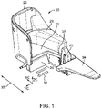
- FIG. 1 illustrates an exemplary passenger seat construction shown generally at reference numeral 20.
- the passenger seat construction 20 generally includes seat elements such as a seat bottom 22, a leg rest 24, and a seat back (not shown). At least one of the seat elements are adjustable such that the seat can be in an upright sitting position for TTOL and a reclined position during flight.
- the reclined position can be any position between the upright sitting position and a bed.
- the reclined position can include a lounge sitting position in which the seat back is upright and the leg rest is horizontal.
- the passenger living space may be at least partially defined by a partition wall 26.
- the partition wall 26 extends from aft the of the seat and along one side of the seat adjacent the aisle.
- the partition wall 26 transitions into a console 28 on the seat side opposite the aisle.
- Other partition wall configurations are envisioned for defining the living space and enhancing or relaxing privacy.
- the aisle, indicated at reference numeral 30, may be a longitudinal aisle parallel to the aircraft longitudinal axis.
- Seat ingress and egress from the aisle 30 is through the path 32 directly forward of the seat bottom 22 that provides passenger leg room in the upright sitting position.
- the leg rest 24 may stow vertically against the front of the seat when the seat is fully upright, thus leaving open the legroom space and path 32.
- An ottoman 34 is positioned forward and spaced apart from the front of the seat.
- the ottoman 34 spacing is such that the leg rest 24, or the seat bottom 22 when no leg rest is included in the seat construction, is spaced apart from the ottoman when the seat is fully reclined.
- the spacing of the ottoman 34 and the seat bottom 22 or leg rest 24 provides a gap between the two, and thus a discontinuous bed when the seat is fully reclined.
- the seat bottom 22 and ottoman 34 may connect through an intermediate connecting portion 38 providing in a peninsula-shaped seat construction.
- a deployable infill assembly 40 is positioned between the ottoman 34 and the seat, and more particularly, between the ottoman 34 and the connecting portion 38. In some embodiments, a portion of the deployable infill assembly 40 may be part of the connecting portion 38.
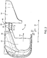
- FIG. 2 is an overhead view of the seat construction 20.
- Directional arrow 42 indicates the seat recline direction and directional arrow 44 indicates the deployment direction of a cushion assembly 46.
- the seat recline direction is parallel to the longitudinal seat axis and the cushion assembly deployment direction is perpendicular to the seat recline direction.
- This arrangement allows the cushion assembly to deploy laterally in a minimum footprint needed for the transition, allows the seat to recline freely without interference from the ottoman 34 or the infill assembly 40, allows the infill assembly 40 to be positioned out of the path 32, and allows the cushion assembly 46 to stow outside of the path 32.
- the arrangement of the elements also allows the use of the ottoman 34 when the cushion assembly 46 is stowed or deployed.
- the infill assembly 40 further includes a separate cushion 48 affixed atop the assembly separate from the deployable cushion assembly 46, which forms part of the connecting portion 38 between the seat bottom 22 and the ottoman 34.
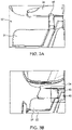
- FIG. 3A is a detailed view showing the cushion assembly 46 fully stowed with a gap between the leg rest 24 and the ottoman 34, and thus a clear ingress/egress path 32.
- the cushion assembly 46 when fully stowed is vertical or near vertical.
- FIG. 3B is a detailed view showing the cushion assembly 46 fully deployed filling the gap between the leg rest 24 and the ottoman 34 to provide a continuous seat surface or bed.
- the bed may be completed by the horizontally-aligned elements including the seat back, seat bottom 22, leg rest 24, cushion assembly 46, separate cushion 48, and ottoman 34.
- the width of the cushion assembly 46 may correspond to the distance between the nearest facing edge of the ottoman and nearest facing end of the closest seat element (e.g., leg rest) when fully reclined.
- the length of the cushion assembly 46 can be customized. As shown, the cushion assembly 46 has a length to extend from the separate cushion 48 to a point short of the lateral extent of the leg rest 22 nearest the aisle. This predetermined length substantially fills the space between the adjusted leg rest 22 and the ottoman 34, while leaving open a small portion of the ingress/egress path 32 adjacent the aisle.
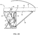
- FIGS. 4A and 4B show an embodiment of the deployable infill assembly 40.
- the infill assembly generally includes the cushion assembly 46 movably coupled to a frame 50.
- the frame 50 may be affixed to the seat construction or to the floor.
- the frame 50 is static and the cushion assembly 46 moves relative to the static frame 50 to transition the cushion assembly between the fully stowed position shown in FIG. 4A and the fully deployed position shown in FIG. 4B .
- the cushion assembly 46 is vertical or substantially vertical when fully stowed, and horizontal or substantially horizontal when fully deployed. In some embodiments it is possible to lock the cushion assembly 46 in at least one intermediate position between fully stowed and fully deployed.
- the frame 50 includes spaced frame members 52 (see also FIG. 5A ) and guide tracks 54.
- the cushion assembly 46 carries at least one guide 56 engaged to travel along the guide tracks 54 to transition the cushion assembly between the stowed and deployed positions.
- the guide tracks may be symmetrically arranged on the spaced frame members 52 to stably support the movement of the cushion assembly and maintain squareness.
- the cushion assembly 46 generally includes a base 58.
- a covered cushion 60 is affixed to one side of the base 58 and the at least one guide 56 is positioned on the opposing side of the base inward of an end of the base.
- each guide track includes a linear portion 62 and an arcuate portion 64, wherein the linear portions 62 guide linear movement of the cushion assembly 46 during initial movement of the cushion assembly away from the fully stowed position and the arcuate portions 64 guide rotational movement of the cushion assembly 46 as the cushion assembly nears the fully deployed position, to provide a low deployment trajectory.
- the movement of the cushion assembly 46 during deployment and stowage includes both translational and rotational aspects such that the cushion assembly stows between the spaced frame members 52 and deploys along a low deployment trajectory to a cantilevered position resting atop the frame 50.
- the facing edges of the cushion assembly 46 and the separate cushion 48 may have opposite chamfers 66 for clearance as the cushion assembly transitions.
- the infill assembly 40 further includes a support element 68 coupled between the frame 50 and the cushion assembly 46.
- the support element 68 moves with the cushion assembly 46 as the cushion assembly transitions between the stowed and deployed positions.
- the support element 68 is pivotally attached at one end to the frame 50 and at an opposing end to the cushion assembly 46.
- the support element 68 stows vertically against the bottom of the cushion assembly 46 in the stowed position and deploys to diagonal to provide support to the overhanging end of the cantilevered cushion assembly.
- the infill assembly 40 further includes a spring-loaded lever 70 pivotally attached at one end to the frame 50.
- the lever 70 has a free end that intersects one of the guide tracks 54 to contact the at least one guide 56 at a predetermined position along a length of the respective one of the guide tracks to slow movement of the cushion assembly 46 toward the stowed position.
- the spring-loaded lever 70 further provides an initial lifting force that acts on the cushion assembly 46 during initial movement of the cushion assembly away from the stowed position, to help lift the cushion assembly.
- FIGS. 5A-5C show the infill assembly 40 including a recess 72 in the bottom of the cushion assembly 46 that receives the support element 68 therein when the cushion assembly is fully stowed. This construction allows the support element 68 to stow entirely within the bottom of the cushion to provide a more compact package and position the support element further out of the ingress/egress path.
- FIG. 5A further shows the stowed cushion assembly 46 between the spaced frame elements 52.
- FIG. 5B shows the cushion assembly 46 partially deployed and with the support element 68 pivotally attached at one end to a transverse frame member 74 and the opposing end of the support element pivotally attached within one end of the recess 72.
- FIG. 5C shows the cushion assembly 46 fully deployed to extend into the ingress/egress path.
Landscapes
- Engineering & Computer Science (AREA)
- Aviation & Aerospace Engineering (AREA)
- Transportation (AREA)
- Mechanical Engineering (AREA)
- Passenger Equipment (AREA)
- Mattresses And Other Support Structures For Chairs And Beds (AREA)
Description
- The construction of passenger seats for aircraft and other conveyances is determined according to seating class. For example, aircraft passenger cabins may be configured with one or more of economy, premium economy and business seating classes. Economy and premium economy seating classes are typically configured with rows of closely-spaced seat groupings wherein individual seats lack lower leg support and have limited seat back recline due to the relatively short seat pitch. Business seating classes may be configured with larger seats and living spaces, wherein the comparatively long seat pitch allows greater seat adjustability. In some configurations, premium seats can adjust between a seat and a bed.
- Conventional lie-flat seat constructions typically include a seat back, seat bottom and leg rest that move into horizontal alignment to form the bed. In some seat constructions, the combined longitudinal length of the seat elements is less than the desired bed length. In other seat constructions, the seat may include an ottoman forward of the seat that meets the leg rest when the seat is fully reclined. This configuration may position the ottoman too close to the seat when upright, thereby limiting leg room and compromising a safe seat ingress and egress path to the seat.
- In some configurations, it may desirable to space the ottoman far from the seat to provide additional leg room when the seat is upright or adjusted short of fully lie-flat. In such configurations, it may be difficult, impractical or impossible to translate a seat element far enough to meet the spaced ottoman, leaving a gap between the ottoman and the nearest seat element and resulting in a discontinuous bed uncomfortable for sleeping.
- Accordingly, it would be desirable to provide a solution for the abovementioned problem, taking into account safety aspects related to aircraft regulations..
- To achieve the foregoing, according to a first aspect the present invention provides a deployable infill assembly according to claim 1.
- United States patent application
US 2011/0253838 A1 discloses an aircraft fixed seat providing an alternative seating position when the convertible seat is in bed configuration and a seat for a friend when the convertible seat is in seat configuration. The convertible seat has a seat squab, a backrest and a leg rest both pivotally connected to the seat squab that are reclinable via a reclining mechanism. It also discloses a bed portion, which can be withdrawn from a stowed upright position, and swung over a space between the seat squab and a foot rest to a level position. A leg is pivoted to the underside of the bed portion and springs out to a strutted position. - United States patent
US 7517010 B2 discloses a seat for an aircraft including a seating surface, a backrest and two armrests. The seat also includes a mechanism for guiding at least one of the armrests in translation in an essentially-vertical direction. - United States patent application
US 2174622 A discloses an improved aircraft chair having a novel retractable leg and foot rest. The leg and foot rest is composed of two sections connected by means of a hinge, in such manner that the foot section can be folded under leg section. - United States patent
US 9022320 B2 - In some embodiments, the at least one guide may be positioned on a bottom of the cushion assembly inward of an end of the cushion assembly nearest the frame when the cushion assembly is in the deployed position.
- In some embodiments, the guide tracks may each include a linear portion and an arcuate portion, the linear portion guiding linear movement of the cushion assembly during initial movement of the cushion assembly away from the stowed position, and the arcuate portion guiding rotational movement of the cushion assembly as the cushion assembly nears the deployed position.
- In some embodiments, the cushion assembly may be disposed between the spaced frame members when in the stowed position, and wherein the cushion assembly may be positioned above the spaced frame members when in the deployed position.
- In some embodiments, the assembly may further include a cushion affixed atop the frame separate from the cushion assembly, and wherein the cushion and the cushion assembly reside in a same horizontal plane when the cushion assembly is in the deployed position.
- In some embodiments, the assembly may further include a spring-loaded lever pivotally attached at one end to the frame, the spring-loaded lever having a free end intersecting one of the guide tracks to contact the at least one guide at a predetermined position along a length of the respective one of the guide tracks to slow movement of the cushion assembly as the guide moves toward the stowed position, and the spring-loaded lever providing an initial lifting force acting on the at least one guide during initial movement of the cushion assembly away from the stowed position.
- In a second aspect, the present invention provides a passenger seat construction according to claim 6.
- In some embodiments, the seat element may be a leg rest or a seat bottom, and wherein the seat element is movable between a first position corresponding to an upright sitting position of the passenger seat, and a second position corresponding to a lounge or bed configuration of the passenger seat.
- In some embodiments, the infill assembly may further include a cushion affixed atop the frame separate from the cushion assembly, and wherein the cushion and the cushion assembly reside in a same horizontal plane when the cushion assembly is in the deployed position.
- In some embodiments, the seat construction comprises a premium class passenger seat construction according to claim 9.
- In some embodiments, the infill assembly may include a static frame including spaced frame elements and guide tracks, at least one guide coupled to the cushion element, for example a cushion assembly, and engaged in the guide tracks, and a support element pivotally attached between the cushion element, for example a cushion assembly, and the static frame, wherein the support element moves with the cushion assembly as the cushion assembly transitions between the stowed and deployed positions.
- The present invention may be better understood when consideration is given to the following detailed description thereof. Such description makes reference to the included drawings, which are not necessarily to scale, and in which some features may be exaggerated, and some features may be omitted or may be represented schematically in the interest of clarity. Like reference numbers in the drawings may represent and refer to the same or similar element, feature, or function. In the drawings:
-
FIG. 1 is a perspective view of a non-limiting example of a passenger seat construction including an ottoman and a deployable bed infill assembly according to an embodiment of the present invention; -
FIG. 2 is a top plan view of the seat construction ofFIG. 1 showing the bed infill assembly in a stowed position; -
FIG. 3A is a fragmentary top perspective view of the seat construction ofFIG. 2 showing the bed infill assembly in a stowed position; -
FIG. 3B is a fragmentary top perspective view of the seat construction ofFIG. 2 showing the bed infill assembly in a deployed position; -
FIG. 4A is a side view of the deployable bed infill assembly showing the cushion assembly in the stowed position; -
FIG. 4B is a side view of the deployable bed infill assembly showing the cushion assembly in the deployed position; -
FIG. 5A is a perspective view of the deployable bed infill assembly showing the cushion assembly fully stowed; -
FIG. 5B is a perspective view of the deployable bed infill assembly showing the cushion assembly partially deployed; and -
FIG. 5C is a perspective view of the deployable bed infill assembly showing the cushion assembly fully deployed. - The description set forth below in connection with the appended drawings is intended to be a description of various, illustrative embodiments of the disclosed subject matter. Specific features and functionalities are described in connection with each illustrative embodiment; however, it will be apparent to those skilled in the art that the disclosed embodiments may be practiced without each of those specific features and functionalities. The aspects, features and functions described below in connection with one embodiment are intended to be applicable to the other embodiments described below except where expressly stated or where an aspect, feature or function is incompatible with an embodiment.
- With reference to the drawing figures, disclosed herein the present invention provides deployable infill assemblies, such as furniture pieces, for use with various passenger seat constructions. The assemblies may be separate from or an integrated part of the passenger seat construction. The assemblies generally include a deployable cushion assembly being configured to stow between uses outside of the passenger seat ingress and egress path and deploy laterally for use into the seat ingress and egress path. The cushion assembly is selectively deployable as needed to expand the seat length in lounge or bed mode, for example, to support the legs or complete a bed.
- For example, a passenger seat construction comprises a seat back, seat bottom and leg rest that adjust to reconfigure the seat in an upright sitting position for taxi, take-off and landing (TTOL) and a reclined sitting position during flight, with various achievable intermediate sitting positions therebetween. In some seat constructions, the seat can recline fully to form a bed in which the surfaces of the seat back, seat bottom and leg rest are horizontally aligned. In such a seat construction, the cushion assembly can deploy perpendicular to the direction of seat recline (e.g., longitudinal seat axis) such that the deployed cushion assembly meets the forwardmost edge of the horizontal leg rest to expand the longitudinal length of the relined seat or bed. In seat constructions lacking a leg rest, the cushion assembly can deploy to meet the forwardmost edge of the seat bottom to expand the longitudinal seat length. In yet other seat constructions, in accordance with embodiments of the present invention, an ottoman is positioned space forward apart from the seat, and the cushion assembly may deploy to meet the facing edges of both the leg rest (or seat bottom) and the ottoman to provide a continuous seat or bed from the seat back thru the ottoman.
- Benefits of the infill assembly include, but are not limited to, expanded bed lengths, larger living spaces, allowing the use of fixed ottomans, shorter required seat element translation distances, and less complex seat recline mechanisms. Particular advantages of the infill assemblies disclosed herein include, but are not limited to, a minimal volume of free space required to allow the transition from stowed to deployed, the simplicity of the assembly by employing a single support on one end and guides defining the trajectory on the other end, a spring loaded lever that pushes out the lower portion of the cushion assembly when stowed, and a predetermined curvature that the guides travel to allow a user to deploy the cushion assembly without mechanical assistance. The deployable infill assembly further allows for seat constructions not previously achievable without such an assembly. Uses of the infill assembly include a bed extension, separate ottoman, meal table, etc.
-
FIG. 1 illustrates an exemplary passenger seat construction shown generally atreference numeral 20. Thepassenger seat construction 20 generally includes seat elements such as a seat bottom 22, aleg rest 24, and a seat back (not shown). At least one of the seat elements are adjustable such that the seat can be in an upright sitting position for TTOL and a reclined position during flight. The reclined position can be any position between the upright sitting position and a bed. For example, the reclined position can include a lounge sitting position in which the seat back is upright and the leg rest is horizontal. - The passenger living space may be at least partially defined by a
partition wall 26. As shown, thepartition wall 26 extends from aft the of the seat and along one side of the seat adjacent the aisle. Thepartition wall 26 transitions into aconsole 28 on the seat side opposite the aisle. Other partition wall configurations are envisioned for defining the living space and enhancing or relaxing privacy. The aisle, indicated atreference numeral 30, may be a longitudinal aisle parallel to the aircraft longitudinal axis. Seat ingress and egress from theaisle 30 is through thepath 32 directly forward of the seat bottom 22 that provides passenger leg room in the upright sitting position. Theleg rest 24 may stow vertically against the front of the seat when the seat is fully upright, thus leaving open the legroom space andpath 32. - An
ottoman 34 is positioned forward and spaced apart from the front of the seat. Theottoman 34 spacing is such that theleg rest 24, or the seat bottom 22 when no leg rest is included in the seat construction, is spaced apart from the ottoman when the seat is fully reclined. The spacing of theottoman 34 and the seat bottom 22 orleg rest 24 provides a gap between the two, and thus a discontinuous bed when the seat is fully reclined. The seat bottom 22 andottoman 34 may connect through an intermediate connectingportion 38 providing in a peninsula-shaped seat construction. Adeployable infill assembly 40 is positioned between theottoman 34 and the seat, and more particularly, between theottoman 34 and the connectingportion 38. In some embodiments, a portion of thedeployable infill assembly 40 may be part of the connectingportion 38. -
FIG. 2 is an overhead view of theseat construction 20.Directional arrow 42 indicates the seat recline direction anddirectional arrow 44 indicates the deployment direction of acushion assembly 46. The seat recline direction is parallel to the longitudinal seat axis and the cushion assembly deployment direction is perpendicular to the seat recline direction. This arrangement allows the cushion assembly to deploy laterally in a minimum footprint needed for the transition, allows the seat to recline freely without interference from theottoman 34 or theinfill assembly 40, allows theinfill assembly 40 to be positioned out of thepath 32, and allows thecushion assembly 46 to stow outside of thepath 32. The arrangement of the elements also allows the use of theottoman 34 when thecushion assembly 46 is stowed or deployed. Theinfill assembly 40 further includes aseparate cushion 48 affixed atop the assembly separate from thedeployable cushion assembly 46, which forms part of the connectingportion 38 between the seat bottom 22 and theottoman 34. -
FIG. 3A is a detailed view showing thecushion assembly 46 fully stowed with a gap between theleg rest 24 and theottoman 34, and thus a clear ingress/egress path 32. Thecushion assembly 46 when fully stowed is vertical or near vertical.FIG. 3B is a detailed view showing thecushion assembly 46 fully deployed filling the gap between theleg rest 24 and theottoman 34 to provide a continuous seat surface or bed. The bed may be completed by the horizontally-aligned elements including the seat back, seat bottom 22,leg rest 24,cushion assembly 46,separate cushion 48, andottoman 34. The width of thecushion assembly 46 may correspond to the distance between the nearest facing edge of the ottoman and nearest facing end of the closest seat element (e.g., leg rest) when fully reclined. The length of thecushion assembly 46 can be customized. As shown, thecushion assembly 46 has a length to extend from theseparate cushion 48 to a point short of the lateral extent of theleg rest 22 nearest the aisle. This predetermined length substantially fills the space between theadjusted leg rest 22 and theottoman 34, while leaving open a small portion of the ingress/egress path 32 adjacent the aisle. -
FIGS. 4A and4B show an embodiment of thedeployable infill assembly 40. The infill assembly generally includes thecushion assembly 46 movably coupled to aframe 50. Theframe 50 may be affixed to the seat construction or to the floor. Theframe 50 is static and thecushion assembly 46 moves relative to thestatic frame 50 to transition the cushion assembly between the fully stowed position shown inFIG. 4A and the fully deployed position shown inFIG. 4B . Thecushion assembly 46 is vertical or substantially vertical when fully stowed, and horizontal or substantially horizontal when fully deployed. In some embodiments it is possible to lock thecushion assembly 46 in at least one intermediate position between fully stowed and fully deployed. - The
frame 50 includes spaced frame members 52 (see alsoFIG. 5A ) and guide tracks 54. Thecushion assembly 46 carries at least oneguide 56 engaged to travel along the guide tracks 54 to transition the cushion assembly between the stowed and deployed positions. The guide tracks may be symmetrically arranged on the spacedframe members 52 to stably support the movement of the cushion assembly and maintain squareness. Thecushion assembly 46 generally includes abase 58. A coveredcushion 60 is affixed to one side of thebase 58 and the at least oneguide 56 is positioned on the opposing side of the base inward of an end of the base. - Moving the cushion assembly, which may be manual or actuated, causes the at least one
guide 56 to follow along the guide tracks 54. The length and shape of the guide tracks 54 dictates the deployment and stowage movement of thecushion assembly 46. As shown, each guide track includes a linear portion 62 and an arcuate portion 64, wherein the linear portions 62 guide linear movement of thecushion assembly 46 during initial movement of the cushion assembly away from the fully stowed position and the arcuate portions 64 guide rotational movement of thecushion assembly 46 as the cushion assembly nears the fully deployed position, to provide a low deployment trajectory. The movement of thecushion assembly 46 during deployment and stowage includes both translational and rotational aspects such that the cushion assembly stows between the spacedframe members 52 and deploys along a low deployment trajectory to a cantilevered position resting atop theframe 50. As best shown inFIG. 4B , the facing edges of thecushion assembly 46 and theseparate cushion 48 may haveopposite chamfers 66 for clearance as the cushion assembly transitions. - The
infill assembly 40 further includes asupport element 68 coupled between theframe 50 and thecushion assembly 46. Thesupport element 68 moves with thecushion assembly 46 as the cushion assembly transitions between the stowed and deployed positions. Thesupport element 68 is pivotally attached at one end to theframe 50 and at an opposing end to thecushion assembly 46. Thesupport element 68 stows vertically against the bottom of thecushion assembly 46 in the stowed position and deploys to diagonal to provide support to the overhanging end of the cantilevered cushion assembly. - In some embodiments, the
infill assembly 40 further includes a spring-loadedlever 70 pivotally attached at one end to theframe 50. Thelever 70 has a free end that intersects one of the guide tracks 54 to contact the at least oneguide 56 at a predetermined position along a length of the respective one of the guide tracks to slow movement of thecushion assembly 46 toward the stowed position. The spring-loadedlever 70 further provides an initial lifting force that acts on thecushion assembly 46 during initial movement of the cushion assembly away from the stowed position, to help lift the cushion assembly. -
FIGS. 5A-5C show theinfill assembly 40 including arecess 72 in the bottom of thecushion assembly 46 that receives thesupport element 68 therein when the cushion assembly is fully stowed. This construction allows thesupport element 68 to stow entirely within the bottom of the cushion to provide a more compact package and position the support element further out of the ingress/egress path.FIG. 5A further shows the stowedcushion assembly 46 between the spacedframe elements 52.FIG. 5B shows thecushion assembly 46 partially deployed and with thesupport element 68 pivotally attached at one end to atransverse frame member 74 and the opposing end of the support element pivotally attached within one end of therecess 72.FIG. 5C shows thecushion assembly 46 fully deployed to extend into the ingress/egress path. - The foregoing description provides embodiments of the invention by way of example only. It is envisioned that other embodiments that are within the scope of the present invention as defined in the appended claims may perform similar functions and/or achieve similar results.
Claims (9)
- A deployable infill assembly (40), for use between a seat element of a passenger seat and an ottoman positioned spaced-apart from the seat element, comprising:a frame (50) including guide tracks (54);a cushion assembly (46) coupled to the frame (50) movable between a stowed position corresponding to a vertical orientation of the cushion assembly within the frame (50) and a deployed position corresponding to a horizontal orientation of the cushion assembly (46), the cushion assembly in use in the deployed position filling a gap between the seat element and the ottoman; andat least one guide (56) coupled to the cushion assembly (46) engaged to travel within the guide tracks (54);wherein the infill assembly (40) further comprises:a support element (68) pivotally attached to the cushion assembly (46),
characterized in that the support element (68) is pivotally attached at one end to the frame (50) and at an opposing end to the cushion assembly (46); anda recess (72) in the bottom of the cushion assembly (46) that receives the support element (68) therein when the cushion assembly (46) is fully stowed;wherein the support element (68) stows vertically against the bottom of the cushion assembly (46) in the stowed position and deploys to diagonal to provide support to the overhanging end of the cantilevered cushion assembly (46). - The deployable infill assembly (40) according to claim 1, wherein the at least one guide (56) is positioned on a bottom of the cushion assembly (46) inward of an end of the cushion assembly (46) nearest the frame (50) when the cushion assembly (46) is in the deployed position.
- The deployable infill assembly (40) according to one or more of the preceding claims, wherein the guide tracks (54) each include a linear portion (62) and an arcuate portion (64), the linear portion (62) guiding linear movement of the cushion assembly (46) during initial movement of the cushion assembly (46) away from the stowed position, and the arcuate portion (64) guiding rotational movement of the cushion assembly (46) as the cushion assembly (46) nears the deployed position.
- The deployable infill assembly (40) according to one or more of the preceding claims, wherein the cushion assembly (46) is disposed between spaced frame members (52) when in the stowed position, and wherein the cushion assembly (46) is positioned above the spaced frame members (52) when in the deployed position.
- The deployable infill assembly (40) according to one or more of the preceding claims, further comprising a spring-loaded lever (70) pivotally attached at one end to the frame (50), the spring-loaded lever (70) having a free end intersecting one of the guide tracks (54) to contact the at least one guide (56) at a predetermined position along a length of the respective one of the guide tracks (54) to slow movement of the cushion assembly (46) as the guide (56) moves toward the stowed position, and the spring-loaded lever (70) providing an initial lifting force acting on the at least one guide (56) during initial movement of the cushion assembly (46) away from the stowed position.
- A passenger seat construction (20), comprising:a seat element (22, 24);an ottoman (34) positioned spaced-apart from the seat element (22, 24); anda deployable infill assembly (40) according to one or more of the preceding claims;wherein the cushion assembly (46) deploys laterally between the seat element (22, 24) and the ottoman (34).
- The passenger seat construction (20) according to claim 6, wherein the seat element (22, 24) is a leg rest (24) or a seat bottom (22), and wherein the seat element (22, 24) is movable between a first position corresponding to an upright sitting position of the passenger seat, and a second position corresponding to a lounge or bed configuration of the passenger seat.
- The passenger seat construction (20) according to one or more of claims 6 and 7, further comprising a cushion (48) affixed atop the frame (50) separate from the cushion assembly (46), and wherein the cushion (48) and the cushion assembly (46) reside in a same horizontal plane when the cushion assembly (46) is in the deployed position.
- A premium class passenger seat construction (20), comprising:
a peninsula-shaped seat surface including a seat element (22, 24), an ottoman (34), and a connecting portion (38), wherein at least part of the connecting portion (38) is an infill assembly (40) according to one or more of claims 1-5.
Applications Claiming Priority (1)
| Application Number | Priority Date | Filing Date | Title |
|---|---|---|---|
| US16/260,207 US10953780B2 (en) | 2019-01-29 | 2019-01-29 | Deployable infill assembly and passenger seat construction |
Publications (2)
| Publication Number | Publication Date |
|---|---|
| EP3689748A1 EP3689748A1 (en) | 2020-08-05 |
| EP3689748B1 true EP3689748B1 (en) | 2022-11-30 |
Family
ID=68916366
Family Applications (1)
| Application Number | Title | Priority Date | Filing Date |
|---|---|---|---|
| EP19215969.7A Active EP3689748B1 (en) | 2019-01-29 | 2019-12-13 | Deployable infill assembly and passenger seat construction |
Country Status (4)
| Country | Link |
|---|---|
| US (1) | US10953780B2 (en) |
| EP (1) | EP3689748B1 (en) |
| CN (1) | CN111483600B (en) |
| CA (1) | CA3063972A1 (en) |
Families Citing this family (11)
| Publication number | Priority date | Publication date | Assignee | Title |
|---|---|---|---|---|
| US20190047445A1 (en) * | 2016-09-30 | 2019-02-14 | Faraday&Future Inc. | In-vehicle bed assembly |
| EP4046913B1 (en) | 2018-04-04 | 2024-06-05 | Zephyr Aerospace, LLC | Vehicular seating suite configuration |
| USD917906S1 (en) * | 2019-03-28 | 2021-05-04 | Airbus Interiors Services Sas | Seat arrangement |
| USD909783S1 (en) * | 2019-04-03 | 2021-02-09 | Zephyr Aerospace, LLC | Vehicular seating suite arrangement |
| USD911725S1 (en) * | 2019-04-03 | 2021-03-02 | Zephyr Aerospace, LLC | Vehicular seating suite arrangement |
| USD911726S1 (en) * | 2019-04-03 | 2021-03-02 | Zephyr Aerospace, LLC | Vehicular seating suite arrangement |
| USD963366S1 (en) | 2019-09-20 | 2022-09-13 | Canoo Technologies Inc. | Vehicle rear seat |
| US11130578B1 (en) * | 2019-10-24 | 2021-09-28 | B/E Aerospace, Inc. | Adjustable ottoman |
| US20210339868A1 (en) * | 2020-04-30 | 2021-11-04 | Adient Aerospace, Llc | Passenger utility element and seat unit |
| USD994358S1 (en) | 2021-02-02 | 2023-08-08 | Zephyr Aerospace, LLC | Vehicular seating suite |
| EP4082908B8 (en) * | 2021-04-30 | 2025-09-17 | Elevate Aircraft Seating LLC | Passenger utility element and seat unit |
Family Cites Families (40)
| Publication number | Priority date | Publication date | Assignee | Title |
|---|---|---|---|---|
| US2081529A (en) * | 1936-01-02 | 1937-05-25 | Boeing Aircraft Co | Airplane sleeping berth arrangement |
| US2174622A (en) | 1937-06-24 | 1939-10-03 | Glenn L Martin Co | Aircraft furniture |
| US3744843A (en) | 1969-01-17 | 1973-07-10 | American Seating Co | Vehicle chair unit |
| US3813149A (en) | 1971-12-23 | 1974-05-28 | Lawrence Brothers | Pivotal mounting device for stadium seats and the like |
| US3762764A (en) | 1972-02-22 | 1973-10-02 | Rohr Industries Inc | Folding seat for transportation type vehicle |
| US4226469A (en) | 1979-01-23 | 1980-10-07 | Royal Development Company, Inc. | Recliner chair with wall-avoiding action |
| US4620335A (en) * | 1984-12-21 | 1986-11-04 | Dodgen Industries, Inc. | Lower bed structure for a recreational vehicle |
| US4969682A (en) * | 1989-10-02 | 1990-11-13 | General Motors Corporation | Seat assembly with roller seat back hinge |
| US5320411A (en) | 1991-11-25 | 1994-06-14 | Kotobuki Seating Co., Ltd. | Flip-up seat construction |
| AU1184895A (en) | 1993-11-19 | 1995-06-06 | Super Sagless, Inc. | Seating furniture ottoman |
| GB9425078D0 (en) | 1994-12-13 | 1995-02-08 | British Airways Plc | A seating unit |
| US20010000639A1 (en) * | 1997-02-20 | 2001-05-03 | Singapore Airlines Ltd. | Transport accommodation |
| US6641158B2 (en) | 2001-02-15 | 2003-11-04 | American Moto Products, Inc. | Retractable vehicle step |
| CA2625280C (en) * | 2001-08-09 | 2010-08-03 | Virgin Atlantic Airways Limited | A seating system and a passenger accomodation unit for a vehicle |
| DE10259854A1 (en) * | 2002-12-20 | 2004-07-08 | Adam Opel Ag | Foldable seat |
| FR2860194B1 (en) | 2003-09-26 | 2007-02-09 | Airbus | CONVERTIBLE SEAT FOR RECEIVING AN AIRCRAFT PASSENGER |
| US7780230B2 (en) * | 2004-04-30 | 2010-08-24 | Hector Serber | Seat assembly with movable seat and backrest and method |
| GB0425323D0 (en) | 2004-11-17 | 2004-12-22 | Britax Aircraft Interiors Uk L | Aircraft seat |
| DE102005022949A1 (en) * | 2005-05-19 | 2006-11-23 | Recaro Aircraft Seating Gmbh & Co. Kg | Passenger e.g. infant, seat for use in commercial aircraft, has support part movable between storage and usage positions, where support part forms increased child-seat surface by lying over seat surface of seat part in usage position |
| US7850220B2 (en) * | 2005-06-09 | 2010-12-14 | Intier Automotive Inc. | Mono leg transformer seat |
| US7455342B2 (en) | 2005-12-23 | 2008-11-25 | Ford Global Technologies, Llc | Stowable ottoman for a vehicle passenger cabin |
| EP1968814B1 (en) * | 2006-01-05 | 2009-11-11 | Intier Automotive Inc. | Fold flat seat assembly |
| DE102006015180A1 (en) * | 2006-04-01 | 2007-10-04 | Recaro Aircraft Seating Gmbh & Co. Kg | Release device for e.g. aircraft, has table part fixed in stowing position by locking device, where locking device is controlled by adjusting movement of arm rest to release table part into usage position for transportation of passengers |
| EP2342095A4 (en) * | 2008-11-01 | 2018-01-10 | Johnson Controls Technology Company | Collapsible seat |
| WO2010086822A1 (en) * | 2009-01-30 | 2010-08-05 | Air New Zealand Limited | A vehicle seat with reclining back and leg rest |
| WO2011070531A1 (en) * | 2009-12-11 | 2011-06-16 | Air New Zealand Limited | A seat and related leg rest and mechanism and method therefor |
| KR101579432B1 (en) * | 2011-05-20 | 2015-12-23 | 존슨 컨트롤스 테크놀러지 컴퍼니 | Stadium and stowing seat |
| JP2014520700A (en) * | 2011-07-07 | 2014-08-25 | ジョンソン コントロールズ メタルズ アンド メカニズムス ゲーエムベーハー アンド カンパニー カーゲー | Vehicle seat that can move forward in its longitudinal guide and has a folding backrest |
| EP2825458B1 (en) | 2012-03-14 | 2018-11-28 | B/E Aerospace Inc. | Aircraft passenger suite with combination bed |
| CA2866844C (en) * | 2012-03-19 | 2017-09-12 | B/E Aerospace, Inc. | Premium class aircraft passenger suite |
| JP6056525B2 (en) * | 2013-02-12 | 2017-01-11 | トヨタ紡織株式会社 | Seat back interlocking ottoman device |
| CN106132828A (en) * | 2014-04-03 | 2016-11-16 | B/E航空公司 | Extendible leg support for aircraft passenger seat |
| EP3067275B1 (en) * | 2015-03-13 | 2018-01-03 | Volvo Car Corporation | A folding table arrangement for a vehicle seat back |
| US9446849B1 (en) * | 2015-03-27 | 2016-09-20 | Ami Industries, Inc. | Stowable reclining seat with lateral translation linkage |
| US10023315B2 (en) * | 2015-06-24 | 2018-07-17 | B/E Aerospace, Inc. | Passenger seat table assembly |
| DE102016113005A1 (en) * | 2016-07-14 | 2018-01-18 | Recaro Aircraft Seating Gmbh & Co. Kg | Aircraft seat device |
| US11001383B2 (en) * | 2016-12-02 | 2021-05-11 | Ami Industries, Inc. | Suspension recline system |
| US10464679B2 (en) * | 2017-08-22 | 2019-11-05 | Ami Industries, Inc. | Stowable seat with pivoting seat pan for advanced comfort |
| EP3489078B1 (en) * | 2017-11-22 | 2020-08-19 | Adient Engineering and IP GmbH | A vehicle seat |
| US10898000B2 (en) * | 2018-07-26 | 2021-01-26 | United Metal Fabricators, Inc. | Leg extension for procedure chair |
-
2019
- 2019-01-29 US US16/260,207 patent/US10953780B2/en active Active
- 2019-11-29 CA CA3063972A patent/CA3063972A1/en active Pending
- 2019-12-12 CN CN201911273219.8A patent/CN111483600B/en active Active
- 2019-12-13 EP EP19215969.7A patent/EP3689748B1/en active Active
Also Published As
| Publication number | Publication date |
|---|---|
| CN111483600A (en) | 2020-08-04 |
| US10953780B2 (en) | 2021-03-23 |
| CN111483600B (en) | 2024-03-15 |
| US20200238880A1 (en) | 2020-07-30 |
| CA3063972A1 (en) | 2020-07-29 |
| EP3689748A1 (en) | 2020-08-05 |
Similar Documents
| Publication | Publication Date | Title |
|---|---|---|
| US10953780B2 (en) | Deployable infill assembly and passenger seat construction | |
| EP3122632B1 (en) | Aircraft seat with segmented seatback for achieving in-bed lounge sitting position | |
| CA2927634C (en) | Linearly deployable aircraft seat legrest | |
| US8662447B2 (en) | Flexible-usage travel suite | |
| EP2289798B1 (en) | Seating for a passenger vehicle | |
| EP3374266B1 (en) | Aircraft seating arrangement with enhanced lay flat position spacing | |
| JP5492224B2 (en) | Seat array, seat unit, tray table and seat system | |
| JP7600255B2 (en) | Outward facing herringbone seating arrangement | |
| EP1116654A2 (en) | Passenger sleeper seat | |
| US20140159436A1 (en) | Reclining chair | |
| US20220033083A1 (en) | Passenger seat unit for an aircraft cabin | |
| EP3446976B1 (en) | Stowable seat with pivoting seat pan for advanced comfort | |
| EP3512771B1 (en) | Aircraft seat | |
| JP2019534201A (en) | Passenger seat arrangement with retractable armrest | |
| EP4037971B1 (en) | Zero intrusion kinematic and recline mechanism for commercial aircraft seats | |
| EP3572323B1 (en) | Sleep systems for aircraft | |
| US7950743B2 (en) | Leg rest for economy class transportation seat | |
| US12157574B2 (en) | Interior layout of an aircraft cabin and associated method | |
| CA3093286C (en) | Aircraft divan | |
| US10604261B2 (en) | Movable ottoman for an aircraft seat |
Legal Events
| Date | Code | Title | Description |
|---|---|---|---|
| PUAI | Public reference made under article 153(3) epc to a published international application that has entered the european phase |
Free format text: ORIGINAL CODE: 0009012 |
|
| STAA | Information on the status of an ep patent application or granted ep patent |
Free format text: STATUS: THE APPLICATION HAS BEEN PUBLISHED |
|
| AK | Designated contracting states |
Kind code of ref document: A1 Designated state(s): AL AT BE BG CH CY CZ DE DK EE ES FI FR GB GR HR HU IE IS IT LI LT LU LV MC MK MT NL NO PL PT RO RS SE SI SK SM TR |
|
| AX | Request for extension of the european patent |
Extension state: BA ME |
|
| STAA | Information on the status of an ep patent application or granted ep patent |
Free format text: STATUS: REQUEST FOR EXAMINATION WAS MADE |
|
| 17P | Request for examination filed |
Effective date: 20210205 |
|
| RBV | Designated contracting states (corrected) |
Designated state(s): AL AT BE BG CH CY CZ DE DK EE ES FI FR GB GR HR HU IE IS IT LI LT LU LV MC MK MT NL NO PL PT RO RS SE SI SK SM TR |
|
| STAA | Information on the status of an ep patent application or granted ep patent |
Free format text: STATUS: EXAMINATION IS IN PROGRESS |
|
| 17Q | First examination report despatched |
Effective date: 20210531 |
|
| GRAP | Despatch of communication of intention to grant a patent |
Free format text: ORIGINAL CODE: EPIDOSNIGR1 |
|
| STAA | Information on the status of an ep patent application or granted ep patent |
Free format text: STATUS: GRANT OF PATENT IS INTENDED |
|
| INTG | Intention to grant announced |
Effective date: 20220822 |
|
| GRAS | Grant fee paid |
Free format text: ORIGINAL CODE: EPIDOSNIGR3 |
|
| GRAA | (expected) grant |
Free format text: ORIGINAL CODE: 0009210 |
|
| STAA | Information on the status of an ep patent application or granted ep patent |
Free format text: STATUS: THE PATENT HAS BEEN GRANTED |
|
| AK | Designated contracting states |
Kind code of ref document: B1 Designated state(s): AL AT BE BG CH CY CZ DE DK EE ES FI FR GB GR HR HU IE IS IT LI LT LU LV MC MK MT NL NO PL PT RO RS SE SI SK SM TR |
|
| REG | Reference to a national code |
Ref country code: CH Ref legal event code: EP Ref country code: GB Ref legal event code: FG4D |
|
| REG | Reference to a national code |
Ref country code: AT Ref legal event code: REF Ref document number: 1534507 Country of ref document: AT Kind code of ref document: T Effective date: 20221215 |
|
| REG | Reference to a national code |
Ref country code: IE Ref legal event code: FG4D |
|
| REG | Reference to a national code |
Ref country code: DE Ref legal event code: R096 Ref document number: 602019022496 Country of ref document: DE |
|
| REG | Reference to a national code |
Ref country code: LT Ref legal event code: MG9D |
|
| REG | Reference to a national code |
Ref country code: NL Ref legal event code: MP Effective date: 20221130 |
|
| PG25 | Lapsed in a contracting state [announced via postgrant information from national office to epo] |
Ref country code: SE Free format text: LAPSE BECAUSE OF FAILURE TO SUBMIT A TRANSLATION OF THE DESCRIPTION OR TO PAY THE FEE WITHIN THE PRESCRIBED TIME-LIMIT Effective date: 20221130 Ref country code: PT Free format text: LAPSE BECAUSE OF FAILURE TO SUBMIT A TRANSLATION OF THE DESCRIPTION OR TO PAY THE FEE WITHIN THE PRESCRIBED TIME-LIMIT Effective date: 20230331 Ref country code: NO Free format text: LAPSE BECAUSE OF FAILURE TO SUBMIT A TRANSLATION OF THE DESCRIPTION OR TO PAY THE FEE WITHIN THE PRESCRIBED TIME-LIMIT Effective date: 20230228 Ref country code: LT Free format text: LAPSE BECAUSE OF FAILURE TO SUBMIT A TRANSLATION OF THE DESCRIPTION OR TO PAY THE FEE WITHIN THE PRESCRIBED TIME-LIMIT Effective date: 20221130 Ref country code: FI Free format text: LAPSE BECAUSE OF FAILURE TO SUBMIT A TRANSLATION OF THE DESCRIPTION OR TO PAY THE FEE WITHIN THE PRESCRIBED TIME-LIMIT Effective date: 20221130 Ref country code: ES Free format text: LAPSE BECAUSE OF FAILURE TO SUBMIT A TRANSLATION OF THE DESCRIPTION OR TO PAY THE FEE WITHIN THE PRESCRIBED TIME-LIMIT Effective date: 20221130 |
|
| REG | Reference to a national code |
Ref country code: AT Ref legal event code: MK05 Ref document number: 1534507 Country of ref document: AT Kind code of ref document: T Effective date: 20221130 |
|
| PG25 | Lapsed in a contracting state [announced via postgrant information from national office to epo] |
Ref country code: RS Free format text: LAPSE BECAUSE OF FAILURE TO SUBMIT A TRANSLATION OF THE DESCRIPTION OR TO PAY THE FEE WITHIN THE PRESCRIBED TIME-LIMIT Effective date: 20221130 Ref country code: PL Free format text: LAPSE BECAUSE OF FAILURE TO SUBMIT A TRANSLATION OF THE DESCRIPTION OR TO PAY THE FEE WITHIN THE PRESCRIBED TIME-LIMIT Effective date: 20221130 Ref country code: LV Free format text: LAPSE BECAUSE OF FAILURE TO SUBMIT A TRANSLATION OF THE DESCRIPTION OR TO PAY THE FEE WITHIN THE PRESCRIBED TIME-LIMIT Effective date: 20221130 Ref country code: IS Free format text: LAPSE BECAUSE OF FAILURE TO SUBMIT A TRANSLATION OF THE DESCRIPTION OR TO PAY THE FEE WITHIN THE PRESCRIBED TIME-LIMIT Effective date: 20230330 Ref country code: HR Free format text: LAPSE BECAUSE OF FAILURE TO SUBMIT A TRANSLATION OF THE DESCRIPTION OR TO PAY THE FEE WITHIN THE PRESCRIBED TIME-LIMIT Effective date: 20221130 Ref country code: GR Free format text: LAPSE BECAUSE OF FAILURE TO SUBMIT A TRANSLATION OF THE DESCRIPTION OR TO PAY THE FEE WITHIN THE PRESCRIBED TIME-LIMIT Effective date: 20230301 |
|
| PG25 | Lapsed in a contracting state [announced via postgrant information from national office to epo] |
Ref country code: NL Free format text: LAPSE BECAUSE OF FAILURE TO SUBMIT A TRANSLATION OF THE DESCRIPTION OR TO PAY THE FEE WITHIN THE PRESCRIBED TIME-LIMIT Effective date: 20221130 |
|
| P01 | Opt-out of the competence of the unified patent court (upc) registered |
Effective date: 20230608 |
|
| PG25 | Lapsed in a contracting state [announced via postgrant information from national office to epo] |
Ref country code: SM Free format text: LAPSE BECAUSE OF FAILURE TO SUBMIT A TRANSLATION OF THE DESCRIPTION OR TO PAY THE FEE WITHIN THE PRESCRIBED TIME-LIMIT Effective date: 20221130 Ref country code: RO Free format text: LAPSE BECAUSE OF FAILURE TO SUBMIT A TRANSLATION OF THE DESCRIPTION OR TO PAY THE FEE WITHIN THE PRESCRIBED TIME-LIMIT Effective date: 20221130 Ref country code: EE Free format text: LAPSE BECAUSE OF FAILURE TO SUBMIT A TRANSLATION OF THE DESCRIPTION OR TO PAY THE FEE WITHIN THE PRESCRIBED TIME-LIMIT Effective date: 20221130 Ref country code: DK Free format text: LAPSE BECAUSE OF FAILURE TO SUBMIT A TRANSLATION OF THE DESCRIPTION OR TO PAY THE FEE WITHIN THE PRESCRIBED TIME-LIMIT Effective date: 20221130 Ref country code: CZ Free format text: LAPSE BECAUSE OF FAILURE TO SUBMIT A TRANSLATION OF THE DESCRIPTION OR TO PAY THE FEE WITHIN THE PRESCRIBED TIME-LIMIT Effective date: 20221130 Ref country code: AT Free format text: LAPSE BECAUSE OF FAILURE TO SUBMIT A TRANSLATION OF THE DESCRIPTION OR TO PAY THE FEE WITHIN THE PRESCRIBED TIME-LIMIT Effective date: 20221130 |
|
| REG | Reference to a national code |
Ref country code: CH Ref legal event code: PL |
|
| REG | Reference to a national code |
Ref country code: BE Ref legal event code: MM Effective date: 20221231 |
|
| PG25 | Lapsed in a contracting state [announced via postgrant information from national office to epo] |
Ref country code: SK Free format text: LAPSE BECAUSE OF FAILURE TO SUBMIT A TRANSLATION OF THE DESCRIPTION OR TO PAY THE FEE WITHIN THE PRESCRIBED TIME-LIMIT Effective date: 20221130 Ref country code: LU Free format text: LAPSE BECAUSE OF NON-PAYMENT OF DUE FEES Effective date: 20221213 Ref country code: AL Free format text: LAPSE BECAUSE OF FAILURE TO SUBMIT A TRANSLATION OF THE DESCRIPTION OR TO PAY THE FEE WITHIN THE PRESCRIBED TIME-LIMIT Effective date: 20221130 |
|
| REG | Reference to a national code |
Ref country code: DE Ref legal event code: R097 Ref document number: 602019022496 Country of ref document: DE |
|
| PLBE | No opposition filed within time limit |
Free format text: ORIGINAL CODE: 0009261 |
|
| STAA | Information on the status of an ep patent application or granted ep patent |
Free format text: STATUS: NO OPPOSITION FILED WITHIN TIME LIMIT |
|
| PG25 | Lapsed in a contracting state [announced via postgrant information from national office to epo] |
Ref country code: LI Free format text: LAPSE BECAUSE OF NON-PAYMENT OF DUE FEES Effective date: 20221231 Ref country code: IE Free format text: LAPSE BECAUSE OF NON-PAYMENT OF DUE FEES Effective date: 20221213 Ref country code: CH Free format text: LAPSE BECAUSE OF NON-PAYMENT OF DUE FEES Effective date: 20221231 |
|
| 26N | No opposition filed |
Effective date: 20230831 |
|
| PG25 | Lapsed in a contracting state [announced via postgrant information from national office to epo] |
Ref country code: SI Free format text: LAPSE BECAUSE OF FAILURE TO SUBMIT A TRANSLATION OF THE DESCRIPTION OR TO PAY THE FEE WITHIN THE PRESCRIBED TIME-LIMIT Effective date: 20221130 Ref country code: BE Free format text: LAPSE BECAUSE OF NON-PAYMENT OF DUE FEES Effective date: 20221231 |
|
| PG25 | Lapsed in a contracting state [announced via postgrant information from national office to epo] |
Ref country code: HU Free format text: LAPSE BECAUSE OF FAILURE TO SUBMIT A TRANSLATION OF THE DESCRIPTION OR TO PAY THE FEE WITHIN THE PRESCRIBED TIME-LIMIT; INVALID AB INITIO Effective date: 20191213 |
|
| PG25 | Lapsed in a contracting state [announced via postgrant information from national office to epo] |
Ref country code: CY Free format text: LAPSE BECAUSE OF FAILURE TO SUBMIT A TRANSLATION OF THE DESCRIPTION OR TO PAY THE FEE WITHIN THE PRESCRIBED TIME-LIMIT Effective date: 20221130 |
|
| PG25 | Lapsed in a contracting state [announced via postgrant information from national office to epo] |
Ref country code: MK Free format text: LAPSE BECAUSE OF FAILURE TO SUBMIT A TRANSLATION OF THE DESCRIPTION OR TO PAY THE FEE WITHIN THE PRESCRIBED TIME-LIMIT Effective date: 20221130 Ref country code: IT Free format text: LAPSE BECAUSE OF FAILURE TO SUBMIT A TRANSLATION OF THE DESCRIPTION OR TO PAY THE FEE WITHIN THE PRESCRIBED TIME-LIMIT Effective date: 20221130 |
|
| PG25 | Lapsed in a contracting state [announced via postgrant information from national office to epo] |
Ref country code: MC Free format text: LAPSE BECAUSE OF FAILURE TO SUBMIT A TRANSLATION OF THE DESCRIPTION OR TO PAY THE FEE WITHIN THE PRESCRIBED TIME-LIMIT Effective date: 20221130 |
|
| PG25 | Lapsed in a contracting state [announced via postgrant information from national office to epo] |
Ref country code: MC Free format text: LAPSE BECAUSE OF FAILURE TO SUBMIT A TRANSLATION OF THE DESCRIPTION OR TO PAY THE FEE WITHIN THE PRESCRIBED TIME-LIMIT Effective date: 20221130 |
|
| PG25 | Lapsed in a contracting state [announced via postgrant information from national office to epo] |
Ref country code: BG Free format text: LAPSE BECAUSE OF FAILURE TO SUBMIT A TRANSLATION OF THE DESCRIPTION OR TO PAY THE FEE WITHIN THE PRESCRIBED TIME-LIMIT Effective date: 20221130 |
|
| PG25 | Lapsed in a contracting state [announced via postgrant information from national office to epo] |
Ref country code: MT Free format text: LAPSE BECAUSE OF FAILURE TO SUBMIT A TRANSLATION OF THE DESCRIPTION OR TO PAY THE FEE WITHIN THE PRESCRIBED TIME-LIMIT Effective date: 20221130 |
|
| PG25 | Lapsed in a contracting state [announced via postgrant information from national office to epo] |
Ref country code: TR Free format text: LAPSE BECAUSE OF FAILURE TO SUBMIT A TRANSLATION OF THE DESCRIPTION OR TO PAY THE FEE WITHIN THE PRESCRIBED TIME-LIMIT Effective date: 20221130 |
|
| PGFP | Annual fee paid to national office [announced via postgrant information from national office to epo] |
Ref country code: DE Payment date: 20251126 Year of fee payment: 7 |
|
| PGFP | Annual fee paid to national office [announced via postgrant information from national office to epo] |
Ref country code: GB Payment date: 20251119 Year of fee payment: 7 |
|
| PGFP | Annual fee paid to national office [announced via postgrant information from national office to epo] |
Ref country code: FR Payment date: 20251120 Year of fee payment: 7 |