EP3689650A1 - An air conditioning system for a vehicle for public transport - Google Patents
An air conditioning system for a vehicle for public transport Download PDFInfo
- Publication number
- EP3689650A1 EP3689650A1 EP20305075.2A EP20305075A EP3689650A1 EP 3689650 A1 EP3689650 A1 EP 3689650A1 EP 20305075 A EP20305075 A EP 20305075A EP 3689650 A1 EP3689650 A1 EP 3689650A1
- Authority
- EP
- European Patent Office
- Prior art keywords
- air conditioning
- conditioning system
- heating means
- heat exchanger
- vehicle
- Prior art date
- Legal status (The legal status is an assumption and is not a legal conclusion. Google has not performed a legal analysis and makes no representation as to the accuracy of the status listed.)
- Granted
Links
Images

Classifications
-
- B—PERFORMING OPERATIONS; TRANSPORTING
- B60—VEHICLES IN GENERAL
- B60H—ARRANGEMENTS OF HEATING, COOLING, VENTILATING OR OTHER AIR-TREATING DEVICES SPECIALLY ADAPTED FOR PASSENGER OR GOODS SPACES OF VEHICLES
- B60H1/00—Heating, cooling or ventilating devices
- B60H1/22—Heating, cooling or ventilating devices the heat source being other than the propulsion plant
- B60H1/2215—Heating, cooling or ventilating devices the heat source being other than the propulsion plant the heat being derived from electric heaters
- B60H1/2226—Electric heaters using radiation
-
- B—PERFORMING OPERATIONS; TRANSPORTING
- B60—VEHICLES IN GENERAL
- B60H—ARRANGEMENTS OF HEATING, COOLING, VENTILATING OR OTHER AIR-TREATING DEVICES SPECIALLY ADAPTED FOR PASSENGER OR GOODS SPACES OF VEHICLES
- B60H1/00—Heating, cooling or ventilating devices
- B60H1/00357—Air-conditioning arrangements specially adapted for particular vehicles
- B60H1/00371—Air-conditioning arrangements specially adapted for particular vehicles for vehicles carrying large numbers of passengers, e.g. buses
-
- B—PERFORMING OPERATIONS; TRANSPORTING
- B60—VEHICLES IN GENERAL
- B60K—ARRANGEMENT OR MOUNTING OF PROPULSION UNITS OR OF TRANSMISSIONS IN VEHICLES; ARRANGEMENT OR MOUNTING OF PLURAL DIVERSE PRIME-MOVERS IN VEHICLES; AUXILIARY DRIVES FOR VEHICLES; INSTRUMENTATION OR DASHBOARDS FOR VEHICLES; ARRANGEMENTS IN CONNECTION WITH COOLING, AIR INTAKE, GAS EXHAUST OR FUEL SUPPLY OF PROPULSION UNITS IN VEHICLES
- B60K11/00—Arrangement in connection with cooling of propulsion units
- B60K11/06—Arrangement in connection with cooling of propulsion units with air cooling
-
- H—ELECTRICITY
- H05—ELECTRIC TECHNIQUES NOT OTHERWISE PROVIDED FOR
- H05B—ELECTRIC HEATING; ELECTRIC LIGHT SOURCES NOT OTHERWISE PROVIDED FOR; CIRCUIT ARRANGEMENTS FOR ELECTRIC LIGHT SOURCES, IN GENERAL
- H05B3/00—Ohmic-resistance heating
- H05B3/0033—Heating devices using lamps
- H05B3/0038—Heating devices using lamps for industrial applications
- H05B3/0042—Heating devices using lamps for industrial applications used in motor vehicles
-
- B—PERFORMING OPERATIONS; TRANSPORTING
- B60—VEHICLES IN GENERAL
- B60H—ARRANGEMENTS OF HEATING, COOLING, VENTILATING OR OTHER AIR-TREATING DEVICES SPECIALLY ADAPTED FOR PASSENGER OR GOODS SPACES OF VEHICLES
- B60H1/00—Heating, cooling or ventilating devices
- B60H1/00642—Control systems or circuits; Control members or indication devices for heating, cooling or ventilating devices
- B60H1/00814—Control systems or circuits characterised by their output, for controlling particular components of the heating, cooling or ventilating installation
- B60H1/00878—Control systems or circuits characterised by their output, for controlling particular components of the heating, cooling or ventilating installation the components being temperature regulating devices
- B60H2001/00961—Control systems or circuits characterised by their output, for controlling particular components of the heating, cooling or ventilating installation the components being temperature regulating devices comprising means for defrosting outside heat exchangers
Definitions
- This invention concerns an air conditioning system for a vehicle, in particular an air conditioning system for a vehicle for public transport.
- Vehicles for public transport generally comprise an air conditioning system designed to air condition the interior space of the vehicle to be used for public transport.
- an air conditioning system essentially comprises a circuit in which an operating fluid, for example R134a, R407c, passes from the solid phase to the liquid phase exchanging heat with the environment to be heated.
- this circuit comprises several elements such as a recirculation pump, a condenser, and an evaporator.
- This last element is essentially a heat exchanger configured to allow the passage of the operating fluid from the liquid phase to the solid phase and is essentially made in the form of a metal radiator inside which the fluid passes.
- the air conditioning system also comprises ventilation means configured to direct an airflow on the radiator to increase the heat exchange of the operating fluid inside the radiator. This fluid then receives heat via the external surfaces of the radiator and is heated by changing phase.
- a first method consists either in reversing the airflow generated by the ventilation means or the direction of the flow of the operating fluid in the circuit. However, in one case as in the other, the air conditioning system must be deactivated, making it unusable.
- a second method consists in heating the incoming air on the radiator via electrical resistors.
- these resistors consume a lot of energy and, in addition, by heating the air, the efficiency of the air conditioning system is reduced, which consequently increases the vehicles' consumption.
- the invention aims to solve the drawbacks mentioned above.
- Figure 1 schematically shows the shape of a vehicle for public transport 1 comprising an air conditioning system 2 configured to allow the circulation of air conditioning within a space intended for the vehicle 1 passengers.
- the air conditioning system 2 essentially comprises an evaporator 3 configured to change the phase of an air conditioning fluid and to make it flow in a circuit 4 connected to other elements not shown (e.g. a condenser, a pump, etc.).
- the air conditioning system 2 also comprises a ventilation sleeve 5 configured to enable the passage of air conditioning inside the vehicle 1.
- the air conditioning system 2 may comprise a fan heater instead of the ventilation sleeve 5.
- the air conditioning system 2 comprises ventilation means 6 configured to direct an airflow F to the evaporator 3 to improve the latter's heat exchange with the environment.
- the evaporator 3 essentially comprises a heat exchanger, for example a radiator 7 with an essentially prismatic shape and equipped with a first opening 3a and a second opening 3b configured to connect the radiator 7 to the air conditioning circuit 4.
- a heat exchanger for example a radiator 7 with an essentially prismatic shape and equipped with a first opening 3a and a second opening 3b configured to connect the radiator 7 to the air conditioning circuit 4.
- the radiator 7 comprises a front wall 7a, a back wall 7b, a pair of side walls, an upper wall, and a lower wall.
- the front and back walls 7a, 7b are equipped with openings configured to enable the passage of the airflow F generated by the ventilation means 6 through the radiator 7 to increase the heat exchange of the air conditioning fluid with the environment inside the radiator 7.
- the front wall 7a is located opposite the ventilation means 6, while the back wall 7b is opposite this.
- the air conditioning system 2 comprises heating means 10 made separately to the radiator 7 and configured to directly heat at least one wall of the latter, for example the back wall 7b, the coldest, of the radiator 7.
- these heating means 10 are electromagnetic heating means, i.e. radiation heating means.
- the heating means 10 comprise emitters of electromagnetic radiation 11, preferably infrared radiation, i.e. having a wavelength ranging between 700 nm and 1 mm.
- the emitters 11 are arranged around the radiator 7 so as to emit an electromagnetic radiation that heats a wall of the radiator 7 but without interfering with the flow F generated by the ventilation means 6 on the radiator 7. That is, the emitters 11 are located outside the space occupied by the flow F.
- the air conditioning system 2 comprises a first emitter 11 dedicated to the emission towards the front wall 7b of the radiator 7 and a second emitter 11 dedicated to the emission towards the front wall 7a of the radiator 7 and, as mentioned above, located externally with respect to the flow F generated by the ventilation means 6.
- the heating means 10 are electrically connected to an energy source of the vehicle 1, e.g. the battery block (not shown) of the vehicle.
- the air conditioning system 2 also comprises sensor means 12 configured to detect the presence of hoarfrost on the walls of the radiator 7.
- the air conditioning system 2 comprises a first half sensor 12 configured to detect the hoarfrost and/or temperature on one wall 7a and a second half sensor 12 configured to detect the hoarfrost and/or temperature on the other wall 7b.
- These sensors 12 can be of any known type.
- the air conditioning system 2 also comprises an electronic unit 13 electrically connected, with a wired or wireless connection, to sensors 12 and emitters 11 and configured to process the signal of the sensors 12 and command the emitters 11 accordingly.
- the electronic unit 13 may be the ECU of the vehicle 1.
- the electronic unit 13 comprises processing means configured to process the values detected by the sensor means 12 and, accordingly, automatically command the emitters 11 according to the procedure below.
- the operation of the air conditioning system 2 according to the invention is the following.
- the air conditioning system 2 When active, the air conditioning system 2 circulates the fluid of the circuit 4 inside the radiator 7.
- the fluid is heated by the ambient air that is directed through the ventilation means 6 towards the front wall 7a; as a result, this air passes through the radiator 7 outside the back wall 7b, which is then cooled.
- the fluid used, heated inside the radiator 7, is directed towards the ventilation sleeve 5 where, through known heat exchangers, it exchanges heat with the air inside the vehicle, heating it.
- the formation of hoarfrost preferably occurs on the back wall 7b, where the air is cooler.
- the latter in the example described, generate electromagnetic radiation - infra-red in the case described - from the emitters 11, which superficially interacts with the metallic material of the radiator 7 that heats up accordingly.
- the electromagnetic radiation does not interfere with the air and does not decrease the efficiency of the heat exchange. In fact, they only interact with the surface of the walls 7a, 7b, defrosting them.
- the invention also concerns a defrosting process of a heat exchanger 7 of an air conditioning circuit 2 of a vehicle 1 essentially comprising the following steps:
- the heating means 10 it is possible to directly heat the walls of a heat exchanger, i.e. its external surfaces, without heating the air between the ventilation means 6 and the radiator itself. In this way, deterioration in the efficiency of the heat exchange of the air conditioning fluid in the heat exchanger is prevented, by defrosting the heat exchanger when necessary.
- the heating means 10 do not lose energy to heat this air, avoiding increases in vehicle consumption.
- these heating means 10 are not physically placed in the flow F between the ventilation means 6 and the radiator 7, preventing a decrease of the heat exchange between the air and the radiator 7.
- infrared emitters 11 enables the advantages mentioned above to be obtained economically.
- heating means 10 there may be one or more heating means 10, as mentioned, dedicated to the different walls of the evaporator 3.
- the arrangement of the air conditioning system 2 may be different, as may the presence of the detection means 12, and, consequently, of the electronic unit 13.
- the detection means 12 could be temperature sensors and that the emitters 11 could be used to keep the walls 7a, 7b of the radiator 7 above a predetermined temperature.
- the radiation emitted by the emitters 11 may have a different wavelength.
Landscapes
- Engineering & Computer Science (AREA)
- Mechanical Engineering (AREA)
- Physics & Mathematics (AREA)
- Thermal Sciences (AREA)
- Chemical & Material Sciences (AREA)
- Combustion & Propulsion (AREA)
- Transportation (AREA)
- Air-Conditioning For Vehicles (AREA)
Abstract
Description
- This patent application claims priority from Italian patent application no.
102019000001259 - This invention concerns an air conditioning system for a vehicle, in particular an air conditioning system for a vehicle for public transport.
- Vehicles for public transport generally comprise an air conditioning system designed to air condition the interior space of the vehicle to be used for public transport.
- As is well known, an air conditioning system essentially comprises a circuit in which an operating fluid, for example R134a, R407c, passes from the solid phase to the liquid phase exchanging heat with the environment to be heated. For this purpose, this circuit comprises several elements such as a recirculation pump, a condenser, and an evaporator.
- This last element is essentially a heat exchanger configured to allow the passage of the operating fluid from the liquid phase to the solid phase and is essentially made in the form of a metal radiator inside which the fluid passes. The air conditioning system also comprises ventilation means configured to direct an airflow on the radiator to increase the heat exchange of the operating fluid inside the radiator. This fluid then receives heat via the external surfaces of the radiator and is heated by changing phase.
- However, especially in winter or under certain climatic conditions, the environment inside the evaporator is humid and cold, so hoarfrost may form on the radiator surfaces that make up the evaporator. This hoarfrost reduces the heat exchange surface of the radiator and will compromise the performance of the air conditioning system. As a result, vehicle consumption is increased.
- A number of methods are currently known for reducing hoarfrost formation.
- A first method consists either in reversing the airflow generated by the ventilation means or the direction of the flow of the operating fluid in the circuit. However, in one case as in the other, the air conditioning system must be deactivated, making it unusable.
- A second method consists in heating the incoming air on the radiator via electrical resistors. However, these resistors consume a lot of energy and, in addition, by heating the air, the efficiency of the air conditioning system is reduced, which consequently increases the vehicles' consumption.
- It is therefore clear that there is a need to provide air conditioning systems for vehicles for public transport that are high-performing, can be used continuously, and do not allow frost to form on the heat exchangers of the air conditioning system.
- The invention aims to solve the drawbacks mentioned above.
- The objectives mentioned above are achieved via an air conditioning system according to the attached claims.
- Additional characteristics and advantages of the invention will clearly emerge from the description that follows, by way of a non-limiting example only, with reference to the attached drawings, wherein:
-
Figure 1 is a schematic, lateral view of an air conditioning system according to the invention; -
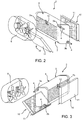
Figure 2 and Figure 3 are perspective views of the system inFigure 1 . -
Figure 1 schematically shows the shape of a vehicle for public transport 1 comprising anair conditioning system 2 configured to allow the circulation of air conditioning within a space intended for the vehicle 1 passengers. - In particular, the
air conditioning system 2 essentially comprises anevaporator 3 configured to change the phase of an air conditioning fluid and to make it flow in acircuit 4 connected to other elements not shown (e.g. a condenser, a pump, etc.). Theair conditioning system 2 also comprises a ventilation sleeve 5 configured to enable the passage of air conditioning inside the vehicle 1. Alternatively, theair conditioning system 2 may comprise a fan heater instead of the ventilation sleeve 5. - In addition, the
air conditioning system 2 comprises ventilation means 6 configured to direct an airflow F to theevaporator 3 to improve the latter's heat exchange with the environment. - In particular, the
evaporator 3 essentially comprises a heat exchanger, for example aradiator 7 with an essentially prismatic shape and equipped with afirst opening 3a and a second opening 3b configured to connect theradiator 7 to theair conditioning circuit 4. - In accordance with the prismatic shape described above, the
radiator 7 comprises afront wall 7a, aback wall 7b, a pair of side walls, an upper wall, and a lower wall. - The front and
back walls radiator 7 to increase the heat exchange of the air conditioning fluid with the environment inside theradiator 7. - In particular, the
front wall 7a is located opposite the ventilation means 6, while theback wall 7b is opposite this. - According to the invention, the
air conditioning system 2 comprises heating means 10 made separately to theradiator 7 and configured to directly heat at least one wall of the latter, for example theback wall 7b, the coldest, of theradiator 7. - In particular, these heating means 10 are electromagnetic heating means, i.e. radiation heating means.
- Advantageously, the heating means 10 comprise emitters of
electromagnetic radiation 11, preferably infrared radiation, i.e. having a wavelength ranging between 700 nm and 1 mm. - In particular, the
emitters 11 are arranged around theradiator 7 so as to emit an electromagnetic radiation that heats a wall of theradiator 7 but without interfering with the flow F generated by the ventilation means 6 on theradiator 7. That is, theemitters 11 are located outside the space occupied by the flow F. - Advantageously, the
air conditioning system 2 comprises afirst emitter 11 dedicated to the emission towards thefront wall 7b of theradiator 7 and asecond emitter 11 dedicated to the emission towards thefront wall 7a of theradiator 7 and, as mentioned above, located externally with respect to the flow F generated by the ventilation means 6. - Advantageously, the heating means 10 are electrically connected to an energy source of the vehicle 1, e.g. the battery block (not shown) of the vehicle.
- The
air conditioning system 2 also comprises sensor means 12 configured to detect the presence of hoarfrost on the walls of theradiator 7. In particular, theair conditioning system 2 comprises afirst half sensor 12 configured to detect the hoarfrost and/or temperature on onewall 7a and asecond half sensor 12 configured to detect the hoarfrost and/or temperature on theother wall 7b. Thesesensors 12 can be of any known type. - Advantageously, the
air conditioning system 2 also comprises anelectronic unit 13 electrically connected, with a wired or wireless connection, tosensors 12 and emitters 11 and configured to process the signal of thesensors 12 and command theemitters 11 accordingly. In particular, theelectronic unit 13 may be the ECU of the vehicle 1. - Preferably, the
electronic unit 13 comprises processing means configured to process the values detected by the sensor means 12 and, accordingly, automatically command theemitters 11 according to the procedure below. - The operation of the
air conditioning system 2 according to the invention is the following. - When active, the
air conditioning system 2 circulates the fluid of thecircuit 4 inside theradiator 7. Here, the fluid is heated by the ambient air that is directed through the ventilation means 6 towards thefront wall 7a; as a result, this air passes through theradiator 7 outside theback wall 7b, which is then cooled. The fluid used, heated inside theradiator 7, is directed towards the ventilation sleeve 5 where, through known heat exchangers, it exchanges heat with the air inside the vehicle, heating it. According to the above, the formation of hoarfrost preferably occurs on theback wall 7b, where the air is cooler. - When the
sensors 12 detect the presence of hoarfrost (or a predetermined temperature) on theback wall 7b or on thefront wall 7a, a resulting signal is detected by theelectronic unit 13 that activates the heating means 10. - The latter, in the example described, generate electromagnetic radiation - infra-red in the case described - from the
emitters 11, which superficially interacts with the metallic material of theradiator 7 that heats up accordingly. - It should be noted that, for the front wall as for the back wall, the electromagnetic radiation does not interfere with the air and does not decrease the efficiency of the heat exchange. In fact, they only interact with the surface of the
walls - The invention also concerns a defrosting process of a
heat exchanger 7 of anair conditioning circuit 2 of a vehicle 1 essentially comprising the following steps: - identifying the presence of hoarfrost and/or of a predetermined temperature on at least one of the
walls radiator 7; - activating the heating means 10 configured to directly heat the walls mentioned above.
- From the above, the advantages of an
air conditioning system 2 according to this invention are clearly evident. - Thanks to the heating means 10, it is possible to directly heat the walls of a heat exchanger, i.e. its external surfaces, without heating the air between the ventilation means 6 and the radiator itself. In this way, deterioration in the efficiency of the heat exchange of the air conditioning fluid in the heat exchanger is prevented, by defrosting the heat exchanger when necessary.
- In addition, the heating means 10 do not lose energy to heat this air, avoiding increases in vehicle consumption.
- In addition, these heating means 10 are not physically placed in the flow F between the ventilation means 6 and the
radiator 7, preventing a decrease of the heat exchange between the air and theradiator 7. - In addition, the use of
infrared emitters 11 enables the advantages mentioned above to be obtained economically. - Finally, it is clear that the
air conditioning system 2 according to this invention can be subject to modifications and variations that do not, however, deviate from the scope of the protection defined by the claims. - For example, there may be one or more heating means 10, as mentioned, dedicated to the different walls of the
evaporator 3. - Again, the arrangement of the
air conditioning system 2 may be different, as may the presence of the detection means 12, and, consequently, of theelectronic unit 13. - It is also clear that the detection means 12 could be temperature sensors and that the
emitters 11 could be used to keep thewalls radiator 7 above a predetermined temperature. - Again, the radiation emitted by the
emitters 11 may have a different wavelength.
Claims (10)
- An air conditioning system (2) for a vehicle (1) for public transport, said air conditioning system (2) comprising a heat exchanger (3) inside which an air conditioning fluid of an air conditioning circuit (4) circulates, configured to exchange heat with the environment, said air conditioning circuit (4) comprising heating means (10) configured to directly heat at least one of the walls (7a, 7b) of said heat exchanger (3), said heating means (10) being separated from said heat exchanger (3) .
- The air conditioning system according to Claim 1, wherein said heating means (10) are electromagnetic heating means.
- The air conditioning system according to Claim 1 or Claim 2, wherein said heating means (10) comprise an electromagnetic radiation emitter (11).
- The air conditioning system according to Claim 3, wherein said electromagnetic radiation has a wavelength of less than 1mm.
- The air conditioning system according to Claim 3 or Claim 4, wherein said electromagnetic radiation has a wavelength ranging between 700 nm and 1 mm.
- The system according to one of the preceding Claims, comprising a first heating means (10) for a first wall (7b) of said heat exchanger (7) and a second heating means (10) for a second wall (7a) of said heat exchanger (7).
- The system according to one of the preceding Claims, comprising ventilation means (6) configured to generate an airflow (F) directed towards at least one of the walls (7a, 7b) of said heat exchanger, said heating means (10) being positioned so as not to interfere with said airflow (F).
- The system according to one of the preceding Claims, comprising sensor means (12) configured to detect the presence of hoarfrost and/or the temperature on at least one of the walls (7a, 7b) of said heat exchanger (3) and an electronic unit (13) electrically connected to said sensor means (12) and to said heating means (10) and configured to control both of the latter based on the signal detected by said sensor means (12).
- A vehicle for public transport comprising an air conditioning system (2) according to the Claims 1 to 8.
- A defrosting process of a heat exchanger (3) of an air conditioning circuit (2) of a vehicle (1) comprising the steps of:• identifying the presence of hoarfrost and/or of a pre-set temperature on at least one of the walls (7a, 7b) of said heat exchanger (3); and• activating heating means (10) configured to directly heat said walls (7a, 7b).
Applications Claiming Priority (1)
| Application Number | Priority Date | Filing Date | Title |
|---|---|---|---|
| IT201900001259 | 2019-01-29 |
Publications (2)
| Publication Number | Publication Date |
|---|---|
| EP3689650A1 true EP3689650A1 (en) | 2020-08-05 |
| EP3689650B1 EP3689650B1 (en) | 2022-12-28 |
Family
ID=66166464
Family Applications (1)
| Application Number | Title | Priority Date | Filing Date |
|---|---|---|---|
| EP20305075.2A Active EP3689650B1 (en) | 2019-01-29 | 2020-01-29 | An air conditioning system for a vehicle for public transport |
Country Status (2)
| Country | Link |
|---|---|
| EP (1) | EP3689650B1 (en) |
| ES (1) | ES2935813T3 (en) |
Citations (2)
| Publication number | Priority date | Publication date | Assignee | Title |
|---|---|---|---|---|
| JPH07205646A (en) * | 1994-01-26 | 1995-08-08 | Mitsubishi Heavy Ind Ltd | Heat pump type air conditioner for vehicle |
| JP2007003170A (en) * | 2005-05-24 | 2007-01-11 | Denso Corp | Ejector type cycle |
Family Cites Families (1)
| Publication number | Priority date | Publication date | Assignee | Title |
|---|---|---|---|---|
| IT201800005938A1 (en) * | 2018-06-01 | 2019-12-01 | HEAT PUMP EQUIPMENT FOR AN AIR CONDITIONING SYSTEM |
-
2020
- 2020-01-29 EP EP20305075.2A patent/EP3689650B1/en active Active
- 2020-01-29 ES ES20305075T patent/ES2935813T3/en active Active
Patent Citations (2)
| Publication number | Priority date | Publication date | Assignee | Title |
|---|---|---|---|---|
| JPH07205646A (en) * | 1994-01-26 | 1995-08-08 | Mitsubishi Heavy Ind Ltd | Heat pump type air conditioner for vehicle |
| JP2007003170A (en) * | 2005-05-24 | 2007-01-11 | Denso Corp | Ejector type cycle |
Also Published As
| Publication number | Publication date |
|---|---|
| ES2935813T3 (en) | 2023-03-10 |
| EP3689650B1 (en) | 2022-12-28 |
Similar Documents
| Publication | Publication Date | Title |
|---|---|---|
| US11180000B2 (en) | Vehicle-mounted temperature controller | |
| US5586448A (en) | Defrosting control system for use in an air-conditioner in an electric vehicle | |
| US20030116637A1 (en) | Heat pump defrost control | |
| US11724623B2 (en) | System for cooling a battery of a motor vehicle, and motor vehicle | |
| US20150101353A1 (en) | Air conditioning system and method for high-voltage battery of vehicle | |
| US10137760B2 (en) | PTC heater for vehicle | |
| CN101871704A (en) | Thermoelectric weather control | |
| JP6554226B2 (en) | Air conditioner | |
| EP0914980A3 (en) | Air conditioning system of vehicles | |
| CN109455059B (en) | Heat pump air conditioner and heat management system integrating water-cooled condenser and water-cooled evaporator | |
| KR101694077B1 (en) | Air conditioning control method for vehicle | |
| CN107531132B (en) | Anti-fog device for vehicle | |
| US20220055452A1 (en) | Refrigeration system for transport vehicle, control method thereof and transport vehicle | |
| CN111619318A (en) | Thermoelectric dehumidification and demisting system and working method thereof in automobile | |
| KR101636700B1 (en) | Heat pump air conditioner having defrost heater | |
| CN115707221A (en) | Roof module with cooling device for forming a vehicle roof | |
| EP3689650B1 (en) | An air conditioning system for a vehicle for public transport | |
| JPH10203148A (en) | Air-conditioner for electric vehicle | |
| US10166834B2 (en) | Heating system of hybrid vehicle and method for controlling the same | |
| WO2017086183A1 (en) | Internal temperature adjusting device | |
| CN112428777A (en) | Automobile heat pump air conditioning system and automobile with same | |
| EP1500536A1 (en) | Control apparatus and control method of vehicle cooling fan | |
| US20220144043A1 (en) | Heating device for vehicle and vehicle | |
| JP2005053474A (en) | Control method and device for cooling fan of vehicle | |
| JP5202055B2 (en) | Vending machine cooling and heating device |
Legal Events
| Date | Code | Title | Description |
|---|---|---|---|
| PUAI | Public reference made under article 153(3) epc to a published international application that has entered the european phase |
Free format text: ORIGINAL CODE: 0009012 |
|
| STAA | Information on the status of an ep patent application or granted ep patent |
Free format text: STATUS: THE APPLICATION HAS BEEN PUBLISHED |
|
| AK | Designated contracting states |
Kind code of ref document: A1 Designated state(s): AL AT BE BG CH CY CZ DE DK EE ES FI FR GB GR HR HU IE IS IT LI LT LU LV MC MK MT NL NO PL PT RO RS SE SI SK SM TR |
|
| AX | Request for extension of the european patent |
Extension state: BA ME |
|
| STAA | Information on the status of an ep patent application or granted ep patent |
Free format text: STATUS: REQUEST FOR EXAMINATION WAS MADE |
|
| 17P | Request for examination filed |
Effective date: 20210204 |
|
| RBV | Designated contracting states (corrected) |
Designated state(s): AL AT BE BG CH CY CZ DE DK EE ES FI FR GB GR HR HU IE IS IT LI LT LU LV MC MK MT NL NO PL PT RO RS SE SI SK SM TR |
|
| STAA | Information on the status of an ep patent application or granted ep patent |
Free format text: STATUS: EXAMINATION IS IN PROGRESS |
|
| 17Q | First examination report despatched |
Effective date: 20210510 |
|
| GRAP | Despatch of communication of intention to grant a patent |
Free format text: ORIGINAL CODE: EPIDOSNIGR1 |
|
| STAA | Information on the status of an ep patent application or granted ep patent |
Free format text: STATUS: GRANT OF PATENT IS INTENDED |
|
| INTG | Intention to grant announced |
Effective date: 20220718 |
|
| GRAS | Grant fee paid |
Free format text: ORIGINAL CODE: EPIDOSNIGR3 |
|
| GRAA | (expected) grant |
Free format text: ORIGINAL CODE: 0009210 |
|
| STAA | Information on the status of an ep patent application or granted ep patent |
Free format text: STATUS: THE PATENT HAS BEEN GRANTED |
|
| AK | Designated contracting states |
Kind code of ref document: B1 Designated state(s): AL AT BE BG CH CY CZ DE DK EE ES FI FR GB GR HR HU IE IS IT LI LT LU LV MC MK MT NL NO PL PT RO RS SE SI SK SM TR |
|
| REG | Reference to a national code |
Ref country code: GB Ref legal event code: FG4D |
|
| REG | Reference to a national code |
Ref country code: CH Ref legal event code: EP |
|
| REG | Reference to a national code |
Ref country code: DE Ref legal event code: R096 Ref document number: 602020007202 Country of ref document: DE |
|
| REG | Reference to a national code |
Ref country code: AT Ref legal event code: REF Ref document number: 1540240 Country of ref document: AT Kind code of ref document: T Effective date: 20230115 |
|
| REG | Reference to a national code |
Ref country code: IE Ref legal event code: FG4D |
|
| REG | Reference to a national code |
Ref country code: ES Ref legal event code: FG2A Ref document number: 2935813 Country of ref document: ES Kind code of ref document: T3 Effective date: 20230310 |
|
| REG | Reference to a national code |
Ref country code: LT Ref legal event code: MG9D |
|
| PG25 | Lapsed in a contracting state [announced via postgrant information from national office to epo] |
Ref country code: SE Free format text: LAPSE BECAUSE OF FAILURE TO SUBMIT A TRANSLATION OF THE DESCRIPTION OR TO PAY THE FEE WITHIN THE PRESCRIBED TIME-LIMIT Effective date: 20221228 Ref country code: NO Free format text: LAPSE BECAUSE OF FAILURE TO SUBMIT A TRANSLATION OF THE DESCRIPTION OR TO PAY THE FEE WITHIN THE PRESCRIBED TIME-LIMIT Effective date: 20230328 Ref country code: LT Free format text: LAPSE BECAUSE OF FAILURE TO SUBMIT A TRANSLATION OF THE DESCRIPTION OR TO PAY THE FEE WITHIN THE PRESCRIBED TIME-LIMIT Effective date: 20221228 Ref country code: FI Free format text: LAPSE BECAUSE OF FAILURE TO SUBMIT A TRANSLATION OF THE DESCRIPTION OR TO PAY THE FEE WITHIN THE PRESCRIBED TIME-LIMIT Effective date: 20221228 |
|
| REG | Reference to a national code |
Ref country code: NL Ref legal event code: MP Effective date: 20221228 |
|
| REG | Reference to a national code |
Ref country code: AT Ref legal event code: MK05 Ref document number: 1540240 Country of ref document: AT Kind code of ref document: T Effective date: 20221228 |
|
| PG25 | Lapsed in a contracting state [announced via postgrant information from national office to epo] |
Ref country code: RS Free format text: LAPSE BECAUSE OF FAILURE TO SUBMIT A TRANSLATION OF THE DESCRIPTION OR TO PAY THE FEE WITHIN THE PRESCRIBED TIME-LIMIT Effective date: 20221228 Ref country code: LV Free format text: LAPSE BECAUSE OF FAILURE TO SUBMIT A TRANSLATION OF THE DESCRIPTION OR TO PAY THE FEE WITHIN THE PRESCRIBED TIME-LIMIT Effective date: 20221228 Ref country code: HR Free format text: LAPSE BECAUSE OF FAILURE TO SUBMIT A TRANSLATION OF THE DESCRIPTION OR TO PAY THE FEE WITHIN THE PRESCRIBED TIME-LIMIT Effective date: 20221228 Ref country code: GR Free format text: LAPSE BECAUSE OF FAILURE TO SUBMIT A TRANSLATION OF THE DESCRIPTION OR TO PAY THE FEE WITHIN THE PRESCRIBED TIME-LIMIT Effective date: 20230329 |
|
| P01 | Opt-out of the competence of the unified patent court (upc) registered |
Effective date: 20230522 |
|
| PG25 | Lapsed in a contracting state [announced via postgrant information from national office to epo] |
Ref country code: NL Free format text: LAPSE BECAUSE OF FAILURE TO SUBMIT A TRANSLATION OF THE DESCRIPTION OR TO PAY THE FEE WITHIN THE PRESCRIBED TIME-LIMIT Effective date: 20221228 |
|
| PG25 | Lapsed in a contracting state [announced via postgrant information from national office to epo] |
Ref country code: SM Free format text: LAPSE BECAUSE OF FAILURE TO SUBMIT A TRANSLATION OF THE DESCRIPTION OR TO PAY THE FEE WITHIN THE PRESCRIBED TIME-LIMIT Effective date: 20221228 Ref country code: RO Free format text: LAPSE BECAUSE OF FAILURE TO SUBMIT A TRANSLATION OF THE DESCRIPTION OR TO PAY THE FEE WITHIN THE PRESCRIBED TIME-LIMIT Effective date: 20221228 Ref country code: PT Free format text: LAPSE BECAUSE OF FAILURE TO SUBMIT A TRANSLATION OF THE DESCRIPTION OR TO PAY THE FEE WITHIN THE PRESCRIBED TIME-LIMIT Effective date: 20230428 Ref country code: EE Free format text: LAPSE BECAUSE OF FAILURE TO SUBMIT A TRANSLATION OF THE DESCRIPTION OR TO PAY THE FEE WITHIN THE PRESCRIBED TIME-LIMIT Effective date: 20221228 Ref country code: CZ Free format text: LAPSE BECAUSE OF FAILURE TO SUBMIT A TRANSLATION OF THE DESCRIPTION OR TO PAY THE FEE WITHIN THE PRESCRIBED TIME-LIMIT Effective date: 20221228 Ref country code: AT Free format text: LAPSE BECAUSE OF FAILURE TO SUBMIT A TRANSLATION OF THE DESCRIPTION OR TO PAY THE FEE WITHIN THE PRESCRIBED TIME-LIMIT Effective date: 20221228 |
|
| PG25 | Lapsed in a contracting state [announced via postgrant information from national office to epo] |
Ref country code: SK Free format text: LAPSE BECAUSE OF FAILURE TO SUBMIT A TRANSLATION OF THE DESCRIPTION OR TO PAY THE FEE WITHIN THE PRESCRIBED TIME-LIMIT Effective date: 20221228 Ref country code: PL Free format text: LAPSE BECAUSE OF FAILURE TO SUBMIT A TRANSLATION OF THE DESCRIPTION OR TO PAY THE FEE WITHIN THE PRESCRIBED TIME-LIMIT Effective date: 20221228 Ref country code: IS Free format text: LAPSE BECAUSE OF FAILURE TO SUBMIT A TRANSLATION OF THE DESCRIPTION OR TO PAY THE FEE WITHIN THE PRESCRIBED TIME-LIMIT Effective date: 20230428 Ref country code: AL Free format text: LAPSE BECAUSE OF FAILURE TO SUBMIT A TRANSLATION OF THE DESCRIPTION OR TO PAY THE FEE WITHIN THE PRESCRIBED TIME-LIMIT Effective date: 20221228 |
|
| REG | Reference to a national code |
Ref country code: CH Ref legal event code: PL |
|
| PG25 | Lapsed in a contracting state [announced via postgrant information from national office to epo] |
Ref country code: MC Free format text: LAPSE BECAUSE OF FAILURE TO SUBMIT A TRANSLATION OF THE DESCRIPTION OR TO PAY THE FEE WITHIN THE PRESCRIBED TIME-LIMIT Effective date: 20221228 Ref country code: LU Free format text: LAPSE BECAUSE OF NON-PAYMENT OF DUE FEES Effective date: 20230129 |
|
| REG | Reference to a national code |
Ref country code: DE Ref legal event code: R097 Ref document number: 602020007202 Country of ref document: DE |
|
| REG | Reference to a national code |
Ref country code: BE Ref legal event code: MM Effective date: 20230131 |
|
| PG25 | Lapsed in a contracting state [announced via postgrant information from national office to epo] |
Ref country code: LI Free format text: LAPSE BECAUSE OF NON-PAYMENT OF DUE FEES Effective date: 20230131 Ref country code: DK Free format text: LAPSE BECAUSE OF FAILURE TO SUBMIT A TRANSLATION OF THE DESCRIPTION OR TO PAY THE FEE WITHIN THE PRESCRIBED TIME-LIMIT Effective date: 20221228 Ref country code: CH Free format text: LAPSE BECAUSE OF NON-PAYMENT OF DUE FEES Effective date: 20230131 |
|
| PLBE | No opposition filed within time limit |
Free format text: ORIGINAL CODE: 0009261 |
|
| STAA | Information on the status of an ep patent application or granted ep patent |
Free format text: STATUS: NO OPPOSITION FILED WITHIN TIME LIMIT |
|
| PG25 | Lapsed in a contracting state [announced via postgrant information from national office to epo] |
Ref country code: BE Free format text: LAPSE BECAUSE OF NON-PAYMENT OF DUE FEES Effective date: 20230131 |
|
| 26N | No opposition filed |
Effective date: 20230929 |
|
| PG25 | Lapsed in a contracting state [announced via postgrant information from national office to epo] |
Ref country code: SI Free format text: LAPSE BECAUSE OF FAILURE TO SUBMIT A TRANSLATION OF THE DESCRIPTION OR TO PAY THE FEE WITHIN THE PRESCRIBED TIME-LIMIT Effective date: 20221228 Ref country code: IE Free format text: LAPSE BECAUSE OF NON-PAYMENT OF DUE FEES Effective date: 20230129 |
|
| GBPC | Gb: european patent ceased through non-payment of renewal fee |
Effective date: 20240129 |
|
| PG25 | Lapsed in a contracting state [announced via postgrant information from national office to epo] |
Ref country code: GB Free format text: LAPSE BECAUSE OF NON-PAYMENT OF DUE FEES Effective date: 20240129 |
|
| PG25 | Lapsed in a contracting state [announced via postgrant information from national office to epo] |
Ref country code: GB Free format text: LAPSE BECAUSE OF NON-PAYMENT OF DUE FEES Effective date: 20240129 |
|
| PG25 | Lapsed in a contracting state [announced via postgrant information from national office to epo] |
Ref country code: BG Free format text: LAPSE BECAUSE OF FAILURE TO SUBMIT A TRANSLATION OF THE DESCRIPTION OR TO PAY THE FEE WITHIN THE PRESCRIBED TIME-LIMIT Effective date: 20221228 |
|
| PG25 | Lapsed in a contracting state [announced via postgrant information from national office to epo] |
Ref country code: BG Free format text: LAPSE BECAUSE OF FAILURE TO SUBMIT A TRANSLATION OF THE DESCRIPTION OR TO PAY THE FEE WITHIN THE PRESCRIBED TIME-LIMIT Effective date: 20221228 |
|
| PG25 | Lapsed in a contracting state [announced via postgrant information from national office to epo] |
Ref country code: CY Free format text: LAPSE BECAUSE OF FAILURE TO SUBMIT A TRANSLATION OF THE DESCRIPTION OR TO PAY THE FEE WITHIN THE PRESCRIBED TIME-LIMIT; INVALID AB INITIO Effective date: 20200129 |
|
| PG25 | Lapsed in a contracting state [announced via postgrant information from national office to epo] |
Ref country code: HU Free format text: LAPSE BECAUSE OF FAILURE TO SUBMIT A TRANSLATION OF THE DESCRIPTION OR TO PAY THE FEE WITHIN THE PRESCRIBED TIME-LIMIT; INVALID AB INITIO Effective date: 20200129 |
|
| PG25 | Lapsed in a contracting state [announced via postgrant information from national office to epo] |
Ref country code: TR Free format text: LAPSE BECAUSE OF FAILURE TO SUBMIT A TRANSLATION OF THE DESCRIPTION OR TO PAY THE FEE WITHIN THE PRESCRIBED TIME-LIMIT Effective date: 20221228 |
|
| PGFP | Annual fee paid to national office [announced via postgrant information from national office to epo] |
Ref country code: ES Payment date: 20260210 Year of fee payment: 7 |
|
| PGFP | Annual fee paid to national office [announced via postgrant information from national office to epo] |
Ref country code: DE Payment date: 20260127 Year of fee payment: 7 |
|
| PGFP | Annual fee paid to national office [announced via postgrant information from national office to epo] |
Ref country code: IT Payment date: 20260108 Year of fee payment: 7 |
|
| PGFP | Annual fee paid to national office [announced via postgrant information from national office to epo] |
Ref country code: FR Payment date: 20260126 Year of fee payment: 7 |