EP3689515A1 - Tool holder for a machine tool - Google Patents
Tool holder for a machine tool Download PDFInfo
- Publication number
- EP3689515A1 EP3689515A1 EP20152087.1A EP20152087A EP3689515A1 EP 3689515 A1 EP3689515 A1 EP 3689515A1 EP 20152087 A EP20152087 A EP 20152087A EP 3689515 A1 EP3689515 A1 EP 3689515A1
- Authority
- EP
- European Patent Office
- Prior art keywords
- switching
- locking
- locking elements
- tool
- tool holder
- Prior art date
- Legal status (The legal status is an assumption and is not a legal conclusion. Google has not performed a legal analysis and makes no representation as to the accuracy of the status listed.)
- Granted
Links
Images


Classifications
-
- B—PERFORMING OPERATIONS; TRANSPORTING
- B23—MACHINE TOOLS; METAL-WORKING NOT OTHERWISE PROVIDED FOR
- B23B—TURNING; BORING
- B23B51/00—Tools for drilling machines
- B23B51/04—Drills for trepanning
- B23B51/0473—Details about the connection between the driven shaft and the tubular cutting part; Arbors
-
- B—PERFORMING OPERATIONS; TRANSPORTING
- B23—MACHINE TOOLS; METAL-WORKING NOT OTHERWISE PROVIDED FOR
- B23B—TURNING; BORING
- B23B31/00—Chucks; Expansion mandrels; Adaptations thereof for remote control
- B23B31/02—Chucks
- B23B31/10—Chucks characterised by the retaining or gripping devices or their immediate operating means
- B23B31/107—Retention by laterally-acting detents, e.g. pins, screws, wedges; Retention by loose elements, e.g. balls
- B23B31/1078—Retention by wedges
-
- E—FIXED CONSTRUCTIONS
- E21—EARTH OR ROCK DRILLING; MINING
- E21B—EARTH OR ROCK DRILLING; OBTAINING OIL, GAS, WATER, SOLUBLE OR MELTABLE MATERIALS OR A SLURRY OF MINERALS FROM WELLS
- E21B12/00—Accessories for drilling tools
-
- B—PERFORMING OPERATIONS; TRANSPORTING
- B23—MACHINE TOOLS; METAL-WORKING NOT OTHERWISE PROVIDED FOR
- B23B—TURNING; BORING
- B23B27/00—Tools for turning or boring machines; Tools of a similar kind in general; Accessories therefor
- B23B27/002—Tools for turning or boring machines; Tools of a similar kind in general; Accessories therefor with vibration damping means
-
- B—PERFORMING OPERATIONS; TRANSPORTING
- B23—MACHINE TOOLS; METAL-WORKING NOT OTHERWISE PROVIDED FOR
- B23B—TURNING; BORING
- B23B31/00—Chucks; Expansion mandrels; Adaptations thereof for remote control
- B23B31/02—Chucks
- B23B31/06—Features relating to the removal of tools; Accessories therefor
-
- B—PERFORMING OPERATIONS; TRANSPORTING
- B23—MACHINE TOOLS; METAL-WORKING NOT OTHERWISE PROVIDED FOR
- B23B—TURNING; BORING
- B23B31/00—Chucks; Expansion mandrels; Adaptations thereof for remote control
- B23B31/02—Chucks
- B23B31/10—Chucks characterised by the retaining or gripping devices or their immediate operating means
- B23B31/107—Retention by laterally-acting detents, e.g. pins, screws, wedges; Retention by loose elements, e.g. balls
- B23B31/1079—Retention by spring or wire
-
- B—PERFORMING OPERATIONS; TRANSPORTING
- B23—MACHINE TOOLS; METAL-WORKING NOT OTHERWISE PROVIDED FOR
- B23Q—DETAILS, COMPONENTS, OR ACCESSORIES FOR MACHINE TOOLS, e.g. ARRANGEMENTS FOR COPYING OR CONTROLLING; MACHINE TOOLS IN GENERAL CHARACTERISED BY THE CONSTRUCTION OF PARTICULAR DETAILS OR COMPONENTS; COMBINATIONS OR ASSOCIATIONS OF METAL-WORKING MACHINES, NOT DIRECTED TO A PARTICULAR RESULT
- B23Q3/00—Devices holding, supporting, or positioning work or tools, of a kind normally removable from the machine
- B23Q3/12—Devices holding, supporting, or positioning work or tools, of a kind normally removable from the machine for securing to a spindle in general
-
- B—PERFORMING OPERATIONS; TRANSPORTING
- B23—MACHINE TOOLS; METAL-WORKING NOT OTHERWISE PROVIDED FOR
- B23B—TURNING; BORING
- B23B2231/00—Details of chucks, toolholder shanks or tool shanks
- B23B2231/04—Adapters
-
- B—PERFORMING OPERATIONS; TRANSPORTING
- B23—MACHINE TOOLS; METAL-WORKING NOT OTHERWISE PROVIDED FOR
- B23B—TURNING; BORING
- B23B2260/00—Details of constructional elements
- B23B2260/004—Adjustable elements
-
- B—PERFORMING OPERATIONS; TRANSPORTING
- B23—MACHINE TOOLS; METAL-WORKING NOT OTHERWISE PROVIDED FOR
- B23B—TURNING; BORING
- B23B51/00—Tools for drilling machines
- B23B51/04—Drills for trepanning
- B23B51/0453—Drills for trepanning with ejecting devices
Definitions
- the invention relates to a tool holder for a machine tool, in particular for a core drilling machine, having a hollow shaft which has, at one end for coupling to the drive of the machine tool, a connector and, at the other end, a receiving opening with a plurality of openings in which locking elements are accommodated which are radially adjustable between a clamping position and an release position for securing a tool accommodated in the receiving opening.
- Tool holders are usually used on machine tools, such as core drilling machines, to fix different tools in the receiving opening of the tool holder and to lock or clamp them therein by means of the locking elements. If, for example, another tool is to be clamped, the already clamped tool can be easily exchanged for the new tool by adjusting the locking elements from the clamping position to the release position.
- These tool holders be can either formed as a separate part in the form of an arbor or as an integral part of the machine tool in the form of a spindle.
- the DE 10 2016 115 094 A1 provides a tool holder, by means of which different tools from different manufacturers with different diameters can be clamped in a single tool holder. Although this mechanism has proved itself in principle, its implementation is constructively quite complex. In addition, it has been shown that the need to clamp tools with different diameters is increasingly reduced as more and more manufacturers use a standard diameter for the tool shank.
- the aim of present invention is therefore to reduce the disadvantages mentioned above and to provide a tool holder, by means of which tools from different manufacturers can be easily clamped and which enables simple handling.
- this task is solved with a tool holder of the type mentioned at the beginning by providing a switching sleeve, which is adjustably mounted on the hollow shaft between a first switching position and a second switching position, a first subset of the locking elements being provided in the first switching position for locking the tool in the receiving opening, and a second subset of the locking elements being provided in the second switching position for locking the tool in the receiving opening, while the adjustment of the respective remaining locking elements is deactivated.
- the locking elements are preferably located in a single plane perpendicular to the longitudinal axis of the hollow shaft.
- the adjustment of the switching sleeve is preferably achieved by turning the sleeve.
- the switching sleeve has at least one switching receiver for receiving the deactivated locking elements.
- the switching receiver ultimately ensures that the locking elements that are not required for clamping the respective tool in the tool holder can remain in the release position.
- the switching receiver it has proved to be particularly effective if the switching receiver is provided twofold and if the angle between the first switching receiver and the second switching receiver is 60°. This allows for clamping a large variety of tools available on the market in the tool holder according to the invention and at the same time the switching sleeve has to be adjusted only over a comparatively small angular range in order to adjust the switching sleeve between the first and the second switching position.
- the switching sleeve can have a switching contour in the form of a collar, by means of which it is possible to move the locking elements radially inwards into the locking position.
- this collar can also be used to accommodate the switching receiver, in which the deactivated locking elements can be accommodated.
- This collar can advantageously be arranged on the inner circumferential side at the end of the switching sleeve facing the muzzle of the receiving opening.
- the switching sleeve only has to be adjusted by a comparatively small angular range in order to clamp tools from different manufacturers that have different positions of the locking element receptacles on the tool side.
- a setting sleeve is provided by means of which the switching sleeve can be axially adjusted between a freeing position releasing the locking elements and a locking position transferring the locking elements from the release position into the clamping position.
- the setting sleeve is non-rotatably connected to the switching sleeve via a pin. This makes it particularly easy to connect the setting sleeve and the switching sleeve.
- the switching sleeve and the setting sleeve are rotationally coupled, it is possible for the user to adjust the switching sleeve between the first and the second position by rotating the setting sleeve.
- the setting sleeve it is possible for the user to both rotate and axially adjust the position of the switching sleeve.
- the setting sleeve is rotatably mounted on the hollow shaft in a limited way. If the switching sleeve and the setting sleeve are rotationally connected, this allows for a positioning of the switching sleeve between the first and the second switching positions in a defined manner.
- a particularly simple operation of the tool holder can be achieved if the switching sleeve is mounted on the outer circumference of the hollow shaft axially adjustable from the locking position into the freeing position against the force of a spring element.
- this also increases the operational reliability of the tool holder, as it ensures that the switching sleeve is always pushed by the spring element, which can be a spring, in the direction of the locking position.
- a retainer which is spring-loaded by a spring in the direction of the muzzle of the receiving opening, is provided in the receiving opening. With this retainer it is possible to hold the locking elements in the release position so that a tool can simply be inserted into the tool holder. In this context, it has proved particularly useful if the locking elements in the release position hold the switching sleeve in its freeing position. If the tool is inserted into the tool holder, the retainer moves axially away from the muzzle of the receiving opening, which frees the locking elements. This allows for the switching sleeve to be transferred from the freeing position to the locking position, by which the first or second subset of locking elements is radially adjusted from the release position to the clamping position.
- an axially adjustable ejector is arranged in the hollow shaft and is spring-loaded by an elastic resetting element in the direction of the receiving opening. By means of this it is possible to receive the pilot pin in an axially adjustable manner. After the cutting process the spring-loaded ejector drives the pilot pin into the direction of to muzzle of the receiving opening to eject the slug out of the cutter after cutting the hole.
- the locking elements each have a cylindrical section and a spherical section for interaction with corresponding tool-side locking element receptacles.
- the cylindrical sections allow the locking elements to be guided within the receiving openings and the spherical sections interact with the locking element receptacles on the tool-side and ensure the locking of the tool in the receiving opening.
- a mounting for a coupling member is formed in the setting sleeve, which is formed in such a way that the coupling member emerges at least partially radially on the inside of the setting sleeve facing the hollow shaft.
- this coupling member ensures that the setting sleeve is guided along the hollow shaft.
- the coupling member is mounted on the switching sleeve.
- a control cam which is delimited by stops defining the first switching position and the second switching position, is formed on the outer circumference of the hollow shaft for receiving the coupling member. This ensures that the adjustment of the setting sleeve is limited.
- the arrangement of the control cam relative to the stops also ensures that adjustment of the switching sleeve between the first and the second switching position can only take place in the, for example, freeing position.
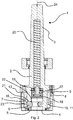
- Figure 1 shows a longitudinal section of a tool holder 1 for a magnetic core drilling machine.
- the tool holder 1 has a hollow shaft 2, which has at one end a connector 3 for connecting the tool holder 1 to the machine tool and which has at the other end a receiving opening 4, in which a tool can be inserted.
- Several openings 5 are formed in the receiving opening 4, in which locking elements 6 are accommodated. These are radially adjustable between a clamping position and an release position in order to secure or release a tool accommodated in the receiving opening 4.
- the tool holder 1 has a switching sleeve 7, which is rotatably mounted on the hollow shaft 2 and is non-rotatably connected via a pin 9 to a setting sleeve 8, which can be gripped by the user.
- the switching sleeve 7 can be rotated to a limited extent relative to the hollow shaft 2 via the setting sleeve 8 between a first switching position and a second switching position.
- a first switching position a first subset of the locking elements 6 is provided for locking the tool in the receiving opening 4.
- the second switching position of the switching sleeve 7 the tool can then locked in the receiving opening 4 via a second subset of the locking elements 6.
- the adjustment of the remaining locking elements 6 is deactivated.
- the switching sleeve 7 can also be adjusted axially along a longitudinal axis 24 of the hollow shaft 2 via the setting sleeve 8 from a freeing position shown in Figure 1 , in which the locking elements 6 can move radially outwards from the clamping position into the release position, and a locking position shown in Figure 2 , in which the locking elements 6 provided for securing the tool in the receiving opening 4 are transferred by the switching sleeve 7 into the clamping position. Therefore, in the freeing position a tool can be inserted into or removed from the receiving opening 4, as the locking elements 6 can be radially adjusted outwards into the release position.
- the first or second subset of the locking elements 6 are transferred to the clamping position - depending on the first or second switching position of the switching sleeve 7 - if the retainer 18 has previously been axially displaced away from the muzzle of the receiving opening 4.
- Figure 2 does not show a tool within the receiving opening 4.
- the switching sleeve 7 has an inwardly pointing collar 23. This collar 23 acts on the locking elements 6 to move them from the release position to the clamping position.
- recesses are formed in the collar 23 of the switching sleeve 7 forming a first switching receiver 10 and a second switching receiver 11, in each of which the deactivated locking element 6 can be accommodated when the switching sleeve 7 is in the first or second switching position.
- the switching sleeve 7 is mounted on the outer circumference of the hollow shaft 2 against the force of a spring element 16, which acts in the direction of the locking position, i.e. away from the muzzle of the receiving opening 4. This ensures that the switching sleeve 7 is always forced in the direction of the locking position, which increases the operational reliability of the tool holder 1, as this prevents unintentional opening of the switching sleeve 7.
- the retainer 18 mounted in the receiving opening 4 is axially displaceable along the longitudinal axis 24 of the hollow shaft 2 against the force of a return spring 17.
- the return spring 17 acts in the direction of the muzzle of the receiving opening 4, whereby the retainer 18 ensures that the locking elements 6 are moved radially outwards into the release position if the switching sleeve 7 is in its freeing position.
- an axially adjustable ejector 19 is arranged in the hollow shaft 2, upon which an elastic resetting element 20 acts in the direction of the receiving opening 4. This ejector 19 is automatically displaced by the pilot pin used in the cutting process and ejects the slug out of the cutter after cutting the hole.
- the sectional view displayed in Figure 3 also shows that three locking elements 6 are provided, with an angle ⁇ of 90° between the first locking element 6.1 and the second locking element 6.2 and an angle ⁇ of 120° formed between the second locking element 6.2 and the third locking element 6.3.
- the first subset of the locking elements 6 is formed from the first locking element 6.1 and the second locking element 6.2.
- the second subset of the locking elements 6, on the other hand, consists of the second locking element 6.2 and the third locking element 6.3. This ultimately results in the fact that the sum of the first subset of the locking elements 6 and the second subset of the locking elements 6 is greater than the total number of locking elements 6.
- one of the three locking elements 6 is used both in the first and in the second switching position for securing the tool in the receiving opening 4. Since only two of the locking elements 6 are used to lock a tool in the receiving opening 4, it is possible to clamp tools whose corresponding locking element receptacles for the locking elements 6 are either 90° or 120° offset from each other.
- the setting sleeve 8 is rotatably mounted on the hollow shaft 2 in a limited way.
- a mounting 12 for a coupling member 13 is provided in the setting sleeve 8.
- the mounting 12 is designed in such a way that the coupling element 13 exits at least partially radially on the inner side of the setting sleeve 8 facing the hollow shaft 2.
- This makes it possible to guide the coupling element 13, which is formed as a cylinder, in a control cam 14 formed on the outer circumference of the hollow shaft 2, as shown in Figure 6 .
- This control cam 14 is limited by stops 15.1 and 15.2, which define the first switching position and the second switching position of the switching sleeve 7.
- the stops 15 are arranged in such a way relative to the control cam 14 that the rotation of the switching sleeve 7 between the first and second switching position is only possible if the switching sleeve 7 is at the same time in the freeing position, i.e. when the switching sleeve 7 is axially adjusted in the direction of the receiving opening 4.
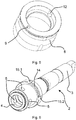
- Figure 4 shows the switching sleeve 7 in a perspective view.
- the collar 23, which is interrupted by the switching receivers 10, 11, can also be seen.
- the angle between the first switching receiver 10 and the second switching receiver 11 is 60°.
- Figure 5 shows in a perspective view the setting sleeve 8 with the mounting 12, which opens on the inner circumference of the setting sleeve 8.
- the mounting 12 houses the coupling element 13 which is guided in the control cam 14 formed in the hollow shaft 2.
- the control cam 14 is limited by the stops 15.
- This adjustment of the locking elements 6 is effected by the axial displacement of the switching sleeve 7 away from the muzzle of the receiving opening 4, which is driven by the spring element 16.
- the locking elements 6 are displaced by the collar 23 of the switching sleeve 7 when it moves axially from the freeing position to the locking position displayed in Figure 2 .
- the ejector 19 is also axially displaced by the pilot pin of the core drill, which is not displayed, away from the receiving opening 4 against the force of the resetting element 20, which is formed by a spring.
- the user wants to remove the tool from the tool holder 1, he simply has to displace the setting sleeve 8, which is connected to the switching sleeve 7 via the pin 9, axially towards the muzzle of the receiving opening 4, whereby the locking elements 6 are released and the tool located in the receiving opening 4 can be removed from the tool holder 1.
- the spring-loaded ejector 19 receives the pilot pin, which ejects the slug out of the cutter after cutting the hole.
- the retainer 18 moves simultaneously, supported by the spring 17 towards the muzzle of the receiving opening 4 and holds the locking elements 6 in the release position.
- the switching sleeve 7 can be rotated on the hollow shaft 2 by an angle of 90° between the first and second switching positions to activate either the first or second subset of locking elements 6 in order to clamp different tools within the tool holder 1.
- this adjustment between the first and second switching position can only be carried out if the switching sleeve 7 is in its freeing position.
Landscapes
- Engineering & Computer Science (AREA)
- Mechanical Engineering (AREA)
- Life Sciences & Earth Sciences (AREA)
- Geology (AREA)
- Mining & Mineral Resources (AREA)
- Physics & Mathematics (AREA)
- Environmental & Geological Engineering (AREA)
- Fluid Mechanics (AREA)
- General Life Sciences & Earth Sciences (AREA)
- Geochemistry & Mineralogy (AREA)
- Gripping On Spindles (AREA)
- Portable Nailing Machines And Staplers (AREA)
Abstract
Description
- The invention relates to a tool holder for a machine tool, in particular for a core drilling machine, having a hollow shaft which has, at one end for coupling to the drive of the machine tool, a connector and, at the other end, a receiving opening with a plurality of openings in which locking elements are accommodated which are radially adjustable between a clamping position and an release position for securing a tool accommodated in the receiving opening.
- Tool holders are usually used on machine tools, such as core drilling machines, to fix different tools in the receiving opening of the tool holder and to lock or clamp them therein by means of the locking elements. If, for example, another tool is to be clamped, the already clamped tool can be easily exchanged for the new tool by adjusting the locking elements from the clamping position to the release position. These tool holders be can either formed as a separate part in the form of an arbor or as an integral part of the machine tool in the form of a spindle.
- However, depending on the manufacturer of the tools, there are differently designed tool shanks, which differ in particular with regard to the tool-side locking element receptacles in which the locking elements of the tool holder engage in order to secure the tool in the tool holder. This is why there are many different tool holders with individual clamping systems from different manufacturers, so that when a tool from another manufacturer shall be used, the tool holder itself has to be exchanged, which means a considerable amount of setup expenditure.
- The
DE 10 2016 115 094 A1 provides a tool holder, by means of which different tools from different manufacturers with different diameters can be clamped in a single tool holder. Although this mechanism has proved itself in principle, its implementation is constructively quite complex. In addition, it has been shown that the need to clamp tools with different diameters is increasingly reduced as more and more manufacturers use a standard diameter for the tool shank. - The aim of present invention is therefore to reduce the disadvantages mentioned above and to provide a tool holder, by means of which tools from different manufacturers can be easily clamped and which enables simple handling.
- According to the invention, this task is solved with a tool holder of the type mentioned at the beginning by providing a switching sleeve, which is adjustably mounted on the hollow shaft between a first switching position and a second switching position, a first subset of the locking elements being provided in the first switching position for locking the tool in the receiving opening, and a second subset of the locking elements being provided in the second switching position for locking the tool in the receiving opening, while the adjustment of the respective remaining locking elements is deactivated.
- This means that it is possible to clamp or mount different tools with differently positioned locking element receptacles on the tool shank with a single tool holder, allowing it for the user to mount tools from different manufacturers with only one tool holder, without changing the tool holder itself. The locking elements are preferably located in a single plane perpendicular to the longitudinal axis of the hollow shaft. The adjustment of the switching sleeve is preferably achieved by turning the sleeve.
- It has also been shown to be particularly favorable if the switching sleeve has at least one switching receiver for receiving the deactivated locking elements. The switching receiver ultimately ensures that the locking elements that are not required for clamping the respective tool in the tool holder can remain in the release position. In the context of this invention, it has proved to be particularly effective if the switching receiver is provided twofold and if the angle between the first switching receiver and the second switching receiver is 60°. This allows for clamping a large variety of tools available on the market in the tool holder according to the invention and at the same time the switching sleeve has to be adjusted only over a comparatively small angular range in order to adjust the switching sleeve between the first and the second switching position. In particular, the switching sleeve can have a switching contour in the form of a collar, by means of which it is possible to move the locking elements radially inwards into the locking position. In particular, this collar can also be used to accommodate the switching receiver, in which the deactivated locking elements can be accommodated. This collar can advantageously be arranged on the inner circumferential side at the end of the switching sleeve facing the muzzle of the receiving opening.
- It has been shown to be particularly favorable if the sum of the first subset of locking elements and the second subset of locking elements is greater than the total number of locking elements. In other words, this means that at least one of the locking elements is used in both the first and the second switching positions to secure the tool in the tool holder. By using at least one of the locking elements in both switching positions to clamp the tool in the tool holder, it is achieved that the switching sleeve only has to be adjusted by a comparatively small angular range in order to clamp tools from different manufacturers that have different positions of the locking element receptacles on the tool side.
- It has also been shown to be advantageous if three locking elements are provided, an angle of 90° being formed between the first locking element and the second locking element and an angle of 120° being formed between the second locking element and the third locking element. This allows a particularly large variety of tools to be clamped. In this context, it has been further proven advantageously if the first subset of the locking elements is formed by the first locking element and the second locking element and that the second subset of the locking elements is formed by the second locking element and the third locking element. This allows tools to be clamped whose locking element receptacles are either 90° or 120° separated from each other. In particular, two locking elements are sufficient to secure a tool securely in the tool holder.
- It has also proved to be advantageous if a setting sleeve is provided by means of which the switching sleeve can be axially adjusted between a freeing position releasing the locking elements and a locking position transferring the locking elements from the release position into the clamping position. In this context, it has also been shown to be advantageous if the setting sleeve is non-rotatably connected to the switching sleeve via a pin. This makes it particularly easy to connect the setting sleeve and the switching sleeve. As the switching sleeve and the setting sleeve are rotationally coupled, it is possible for the user to adjust the switching sleeve between the first and the second position by rotating the setting sleeve. Hence, by means of the setting sleeve it is possible for the user to both rotate and axially adjust the position of the switching sleeve.
- However, it has also proven to be particularly advantageous if the setting sleeve is rotatably mounted on the hollow shaft in a limited way. If the switching sleeve and the setting sleeve are rotationally connected, this allows for a positioning of the switching sleeve between the first and the second switching positions in a defined manner.
- A particularly simple operation of the tool holder can be achieved if the switching sleeve is mounted on the outer circumference of the hollow shaft axially adjustable from the locking position into the freeing position against the force of a spring element. On the one hand, this means that the switching sleeve is automatically transferred from the freeing position to the locking position, so that the user does not have to take any further action to clamp the tool in the receiving opening of the tool holder. In addition, this also increases the operational reliability of the tool holder, as it ensures that the switching sleeve is always pushed by the spring element, which can be a spring, in the direction of the locking position.
- In this context, it has also proved to be favorable if a retainer, which is spring-loaded by a spring in the direction of the muzzle of the receiving opening, is provided in the receiving opening. With this retainer it is possible to hold the locking elements in the release position so that a tool can simply be inserted into the tool holder. In this context, it has proved particularly useful if the locking elements in the release position hold the switching sleeve in its freeing position. If the tool is inserted into the tool holder, the retainer moves axially away from the muzzle of the receiving opening, which frees the locking elements. This allows for the switching sleeve to be transferred from the freeing position to the locking position, by which the first or second subset of locking elements is radially adjusted from the release position to the clamping position.
- The removal of the slug out of the cutter after cutting the hole is facilitated if an axially adjustable ejector is arranged in the hollow shaft and is spring-loaded by an elastic resetting element in the direction of the receiving opening. By means of this it is possible to receive the pilot pin in an axially adjustable manner. After the cutting process the spring-loaded ejector drives the pilot pin into the direction of to muzzle of the receiving opening to eject the slug out of the cutter after cutting the hole.
- It has also proven to be advantageous if the locking elements each have a cylindrical section and a spherical section for interaction with corresponding tool-side locking element receptacles. The cylindrical sections allow the locking elements to be guided within the receiving openings and the spherical sections interact with the locking element receptacles on the tool-side and ensure the locking of the tool in the receiving opening.
- It has also been shown to be favorable if a mounting for a coupling member is formed in the setting sleeve, which is formed in such a way that the coupling member emerges at least partially radially on the inside of the setting sleeve facing the hollow shaft. In particular, this coupling member ensures that the setting sleeve is guided along the hollow shaft. However, it is also possible that the coupling member is mounted on the switching sleeve.
- In this context, it has ultimately also proved its worth if a control cam, which is delimited by stops defining the first switching position and the second switching position, is formed on the outer circumference of the hollow shaft for receiving the coupling member. This ensures that the adjustment of the setting sleeve is limited. In addition, the arrangement of the control cam relative to the stops also ensures that adjustment of the switching sleeve between the first and the second switching position can only take place in the, for example, freeing position.
- The present invention will become more fully understood from the detailed description given hereinbelow and the accompanying drawings which are given by way of illustration only, and thus, are not limitative of the present invention, and wherein:
- Fig. 1
- shows a longitudinal section through a tool holder with a switching sleeve in the freeing position,
- Fig. 2
- a longitudinal section through the tool holder with the switching sleeve in locking position,
- Fig. 3
- a cross-section along the section III-III from
Fig. 1 , - Fig. 4
- a perspective view of the switching sleeve,
- Fig. 5
- a perspective view of a setting sleeve, and
- Fig. 6
- a perspective view of a hollow shaft.
-
Figure 1 shows a longitudinal section of atool holder 1 for a magnetic core drilling machine. Thetool holder 1 has ahollow shaft 2, which has at one end aconnector 3 for connecting thetool holder 1 to the machine tool and which has at the other end a receivingopening 4, in which a tool can be inserted.Several openings 5 are formed in the receivingopening 4, in whichlocking elements 6 are accommodated. These are radially adjustable between a clamping position and an release position in order to secure or release a tool accommodated in the receivingopening 4. In addition, thetool holder 1 has a switchingsleeve 7, which is rotatably mounted on thehollow shaft 2 and is non-rotatably connected via apin 9 to asetting sleeve 8, which can be gripped by the user. The switchingsleeve 7 can be rotated to a limited extent relative to thehollow shaft 2 via the settingsleeve 8 between a first switching position and a second switching position. In the first switching position, a first subset of thelocking elements 6 is provided for locking the tool in the receivingopening 4. In the second switching position of the switchingsleeve 7, the tool can then locked in the receivingopening 4 via a second subset of thelocking elements 6. In the first switching position or the second switching position, the adjustment of the remaininglocking elements 6 is deactivated. On the other hand, the switchingsleeve 7 can also be adjusted axially along alongitudinal axis 24 of thehollow shaft 2 via the settingsleeve 8 from a freeing position shown inFigure 1 , in which thelocking elements 6 can move radially outwards from the clamping position into the release position, and a locking position shown inFigure 2 , in which thelocking elements 6 provided for securing the tool in the receivingopening 4 are transferred by the switchingsleeve 7 into the clamping position. Therefore, in the freeing position a tool can be inserted into or removed from the receivingopening 4, as thelocking elements 6 can be radially adjusted outwards into the release position. In the freeing position of the switchingsleeve 7, shown inFigure 1 , thelocking elements 6 are radially adjusted outwards and are held in this release position by aretainer 18. In this configuration the switchingsleeve 7 is also hold by thelocking elements 6 in the freeing position. - In the locking position of the switching
sleeve 7, which is shown inFigure 2 , the first or second subset of thelocking elements 6 are transferred to the clamping position - depending on the first or second switching position of the switching sleeve 7 - if theretainer 18 has previously been axially displaced away from the muzzle of the receivingopening 4. For a better overview,Figure 2 does not show a tool within the receivingopening 4. To adjust thelocking elements 6, which have acylindrical section 21 and aspherical section 22, the switchingsleeve 7 has an inwardly pointingcollar 23. Thiscollar 23 acts on thelocking elements 6 to move them from the release position to the clamping position. In order to deactivate the adjustment of one of thelocking elements 6 from the release position into the clamping position, recesses are formed in thecollar 23 of the switchingsleeve 7 forming afirst switching receiver 10 and asecond switching receiver 11, in each of which the deactivated lockingelement 6 can be accommodated when the switchingsleeve 7 is in the first or second switching position. - The switching
sleeve 7 is mounted on the outer circumference of thehollow shaft 2 against the force of aspring element 16, which acts in the direction of the locking position, i.e. away from the muzzle of the receivingopening 4. This ensures that the switchingsleeve 7 is always forced in the direction of the locking position, which increases the operational reliability of thetool holder 1, as this prevents unintentional opening of the switchingsleeve 7. Theretainer 18 mounted in the receivingopening 4 is axially displaceable along thelongitudinal axis 24 of thehollow shaft 2 against the force of areturn spring 17. Thereturn spring 17 acts in the direction of the muzzle of the receivingopening 4, whereby theretainer 18 ensures that thelocking elements 6 are moved radially outwards into the release position if the switchingsleeve 7 is in its freeing position. In addition, an axiallyadjustable ejector 19 is arranged in thehollow shaft 2, upon which anelastic resetting element 20 acts in the direction of the receivingopening 4. Thisejector 19 is automatically displaced by the pilot pin used in the cutting process and ejects the slug out of the cutter after cutting the hole. - The sectional view displayed in
Figure 3 also shows that three lockingelements 6 are provided, with an angle α of 90° between the first locking element 6.1 and the second locking element 6.2 and an angle β of 120° formed between the second locking element 6.2 and the third locking element 6.3. Thus, in the example shown, the first subset of thelocking elements 6 is formed from the first locking element 6.1 and the second locking element 6.2. The second subset of thelocking elements 6, on the other hand, consists of the second locking element 6.2 and the third locking element 6.3. This ultimately results in the fact that the sum of the first subset of thelocking elements 6 and the second subset of thelocking elements 6 is greater than the total number of lockingelements 6. In other words, one of the threelocking elements 6 is used both in the first and in the second switching position for securing the tool in the receivingopening 4. Since only two of thelocking elements 6 are used to lock a tool in the receivingopening 4, it is possible to clamp tools whose corresponding locking element receptacles for thelocking elements 6 are either 90° or 120° offset from each other. - In the
tool holder 1 shown, the settingsleeve 8 is rotatably mounted on thehollow shaft 2 in a limited way. For this purpose, a mounting 12 for acoupling member 13 is provided in the settingsleeve 8. The mounting 12 is designed in such a way that thecoupling element 13 exits at least partially radially on the inner side of the settingsleeve 8 facing thehollow shaft 2. This makes it possible to guide thecoupling element 13, which is formed as a cylinder, in acontrol cam 14 formed on the outer circumference of thehollow shaft 2, as shown inFigure 6 . Thiscontrol cam 14 is limited by stops 15.1 and 15.2, which define the first switching position and the second switching position of the switchingsleeve 7. As can also be seen fromFigure 6 , the stops 15 are arranged in such a way relative to thecontrol cam 14 that the rotation of the switchingsleeve 7 between the first and second switching position is only possible if the switchingsleeve 7 is at the same time in the freeing position, i.e. when the switchingsleeve 7 is axially adjusted in the direction of the receivingopening 4. -
Figure 4 shows the switchingsleeve 7 in a perspective view. In particular, thecollar 23, which is interrupted by the switchingreceivers receiver 10 and thesecond switching receiver 11 is 60°. -
Figure 5 shows in a perspective view thesetting sleeve 8 with the mounting 12, which opens on the inner circumference of the settingsleeve 8. The mounting 12 houses thecoupling element 13 which is guided in thecontrol cam 14 formed in thehollow shaft 2. As can be seen fromFigure 6 , which shows thehollow shaft 2 in a perspective illustration, thecontrol cam 14 is limited by the stops 15. - In the following, the function of the invented
tool holder 1 is described once again in detail, starting from the freeing position of the switchingsleeve 7 shown inFigure 1 . In the freeing position of the switchingsleeve 7, thelocking elements 6 are moved radially outwards to the release position by theretainer 18, which is driven by thereturn spring 17 in the direction of the receivingopening 4. In this configuration thelocking elements 6 secure the switchingsleeve 7 in the release position. If now a tool is inserted into the receivingopening 4 of thehollow shaft 2, it first comes into contact with theretainer 18, which is then axially displaced in thehollow shaft 2 against the force of thereturn spring 17. This allows thelocking elements 6, which were previously held in the release position by theretainer 18, to be radially adjusted inward to secure the tool in the receivingopening 4. This adjustment of thelocking elements 6 is effected by the axial displacement of the switchingsleeve 7 away from the muzzle of the receivingopening 4, which is driven by thespring element 16. Thelocking elements 6 are displaced by thecollar 23 of the switchingsleeve 7 when it moves axially from the freeing position to the locking position displayed inFigure 2 . In this state, theejector 19 is also axially displaced by the pilot pin of the core drill, which is not displayed, away from the receivingopening 4 against the force of the resettingelement 20, which is formed by a spring. - If the user wants to remove the tool from the
tool holder 1, he simply has to displace the settingsleeve 8, which is connected to the switchingsleeve 7 via thepin 9, axially towards the muzzle of the receivingopening 4, whereby thelocking elements 6 are released and the tool located in the receivingopening 4 can be removed from thetool holder 1. The spring-loadedejector 19 receives the pilot pin, which ejects the slug out of the cutter after cutting the hole. Theretainer 18 moves simultaneously, supported by thespring 17 towards the muzzle of the receivingopening 4 and holds thelocking elements 6 in the release position. In the displayed example, the switchingsleeve 7 can be rotated on thehollow shaft 2 by an angle of 90° between the first and second switching positions to activate either the first or second subset of lockingelements 6 in order to clamp different tools within thetool holder 1. However, as can be seen in particular fromFigure 6 , this adjustment between the first and second switching position can only be carried out if the switchingsleeve 7 is in its freeing position. -
- 1
- tool holder
- 2
- hollow shaft
- 3
- connector
- 4
- receiving opening
- 5
- opening
- 6
- locking element
- 7
- switching sleeve
- 8
- setting sleeve
- 9
- pin
- 10
- first switching receiver
- 11
- second switching receiver
- 12
- mounting
- 13
- coupling member
- 14
- control cam
- 15
- stop
- 16
- spring element
- 17
- spring
- 18
- retainer
- 19
- ejector
- 20
- resetting element
- 21
- cylindrical section
- 22
- spherical section
- 23
- collar
- 24
- longitudinal axis
Claims (15)
- Tool holder (1) for a machine tool, in particular for a core drilling machine, having a hollow shaft (2) which has, at one end for coupling to the drive of the machine tool, a connector (3) and, at the other end, a receiving opening (4) with a plurality of openings (5) in which locking elements (6) are accommodated which are radially adjustable between a clamping position and an release position for securing a tool accommodated in the receiving opening (4), characterized in that a switching sleeve (7) is provided, which is adjustably mounted on the hollow shaft (2) between a first switching position and a second switching position, a first subset of the locking elements (6) being provided in the first switching position for locking the tool in the receiving opening (4), and a second subset of the locking elements (6) being provided in the second switching position for locking the tool in the receiving opening (4), while the adjustment of the respective remaining locking elements (6) is deactivated.
- The tool holder (1) according to claim 1, characterized in that the switching sleeve (7) has at least one switching receiver (10, 11) for receiving the deactivated locking elements (6).
- The tool holder (1) according to claim 2, characterized in that the switching receiver (10, 11) is provided twofold and the angle between the first switching receiver (10) and the second switching receiver (11) is 60°.
- The tool holder (1) according to any one of claims 1 to 3, characterized in that the sum of the first subset of locking elements (6) and the second subset of locking elements (6) is greater than the total number of locking elements (6).
- The tool holder (1) according to one of claims 1 to 4, characterized in that three locking elements (6) are provided, an angle of 90° being formed between the first locking element (6) and the second locking element (6) and an angle of 120° being formed between the second locking element (6) and the third locking element (6).
- The tool holder (1) according to claim 5, characterized in that the first subset of the locking elements (6) is formed by the first locking element (6) and the second locking element (6) and that the second subset of the locking elements (6) is formed by the second locking element (6) and the third locking element (6).
- The tool holder (1) according to one of claims 1 to 6, characterized in that an setting sleeve (8) is provided by means of which the switching sleeve (7) can be axially adjusted between a freeing position releasing the locking elements (6) and a locking position transferring the locking elements (6) from the release position into the clamping position.
- The tool holder (1) according to claim 7, characterized in that the setting sleeve (8) is non-rotatabley connected to the switching sleeve (7) via a pin (9).
- The tool holder (1) according to one of claims 1 to 8, characterized in that the setting sleeve (8) is rotatably mounted on the hollow shaft (2) in a limited way.
- The tool holder (1) according to one of claims 1 to 9, characterized in that the switching sleeve (7) is mounted on the outer circumference of the hollow shaft (2) axially adjustable from the locking position into the freeing position against the force of a spring element (16).
- The tool holder (1) according to one of claims 1 to 10, characterized in that a retainer (18), which is spring-loaded by a spring (17) in the direction of the muzzle of the receiving opening (4), is provided in the receiving opening (4).
- The tool holder (1) according to one of the claims 1 to 11, characterized in that an axially adjustable ejector (19) is arranged in the hollow shaft (2) and is spring-loaded by an elastic resetting element (20) in the direction of the receiving opening (4).
- The tool holder (1) according to one of claims 1 to 12, characterized in that the locking elements (6) each have a cylindrical section (21) and a spherical section (22) for interaction with corresponding tool-side locking element receptacles.
- The tool holder (1) according to one of the claims 1 to 13, characterized in that a mounting (12) for a coupling member (13) is formed in the setting sleeve (8), which is formed in such a way that the coupling member (13) emerges at least partially radially on the inside of the setting sleeve (8) facing the hollow shaft (2).
- The tool holder (1) according to claim 14, characterized in that a control cam (14), which is delimited by stops (15) defining the first switching position and the second switching position, is formed on the outer circumference of the hollow shaft (2) for receiving the coupling member (13).
Applications Claiming Priority (1)
| Application Number | Priority Date | Filing Date | Title |
|---|---|---|---|
| US16/259,274 US11224923B2 (en) | 2019-01-28 | 2019-01-28 | Tool holder for a machine tool |
Publications (2)
| Publication Number | Publication Date |
|---|---|
| EP3689515A1 true EP3689515A1 (en) | 2020-08-05 |
| EP3689515B1 EP3689515B1 (en) | 2023-06-14 |
Family
ID=69174315
Family Applications (1)
| Application Number | Title | Priority Date | Filing Date |
|---|---|---|---|
| EP20152087.1A Active EP3689515B1 (en) | 2019-01-28 | 2020-01-16 | Tool holder for a machine tool |
Country Status (3)
| Country | Link |
|---|---|
| US (1) | US11224923B2 (en) |
| EP (1) | EP3689515B1 (en) |
| CN (1) | CN111502554A (en) |
Families Citing this family (4)
| Publication number | Priority date | Publication date | Assignee | Title |
|---|---|---|---|---|
| US11998996B2 (en) | 2021-03-19 | 2024-06-04 | Black & Decker Inc. | Hole cutting accessory for power tool |
| EP4086027A1 (en) | 2021-03-19 | 2022-11-09 | Black & Decker Inc. | Hole cutting accessory for power tool |
| AU2023226780A1 (en) | 2022-09-09 | 2024-03-28 | Techtronic Cordless Gp | Connecting device and tool |
| CN120572048B (en) * | 2025-08-06 | 2025-10-31 | 泉州市聪勤机械制造有限公司 | A milling device for CNC equipment and CNC equipment |
Citations (3)
| Publication number | Priority date | Publication date | Assignee | Title |
|---|---|---|---|---|
| US6311989B1 (en) * | 1999-07-13 | 2001-11-06 | Werner Hermann Wera Werke | Chuck for screwdriver inserts |
| DE102016115094A1 (en) | 2016-08-15 | 2018-02-15 | C. & E. Fein Gmbh | Tool holder for a machine tool |
| WO2020077143A1 (en) * | 2018-10-10 | 2020-04-16 | Milwaukee Electric Tool Corporation | Multi-size tool bit holder for a rotary power tool |
Family Cites Families (15)
| Publication number | Priority date | Publication date | Assignee | Title |
|---|---|---|---|---|
| US2327074A (en) * | 1940-07-26 | 1943-08-17 | Floyd C Snyder | Chuck |
| US4944345A (en) * | 1989-03-09 | 1990-07-31 | Otis Engineering Corporation | Well device lock mandrel and running tool |
| AU670373B2 (en) | 1993-06-30 | 1996-07-11 | Nitto Kohki Co., Ltd. | Annular cutter connecting apparatus and annular cutter |
| WO2000066329A1 (en) * | 1999-05-03 | 2000-11-09 | Maxtech Manufacturing Inc. | Quick-connect mechanism |
| WO2002064295A2 (en) * | 2001-02-09 | 2002-08-22 | Maxtech Manufacturing Inc. | Irregular-shank tools and drivers therefor |
| JP3992667B2 (en) | 2003-08-12 | 2007-10-17 | 日東工器株式会社 | electric screwdriver |
| US7494306B2 (en) | 2004-07-16 | 2009-02-24 | Nitto Kohki Co., Ltd. | Rotary cutting machine |
| JP4571480B2 (en) | 2004-11-04 | 2010-10-27 | 本田技研工業株式会社 | Electric motor control device |
| JP4621255B2 (en) | 2006-05-31 | 2011-01-26 | 株式会社ミヤナガ | Shank attachment structure |
| US9101987B2 (en) * | 2009-10-08 | 2015-08-11 | Jore Corporation | Tool connector having multiple seating positions |
| TWI410305B (en) * | 2011-06-30 | 2013-10-01 | Bo Shen Chen | Connection rod structure |
| DE102013103937B4 (en) * | 2013-04-18 | 2014-12-04 | Bilz Werkzeugfabrik Gmbh & Co. Kg | Quick change system for a tool holder |
| DE202013006690U1 (en) | 2013-07-19 | 2013-08-07 | EasyWork UG (haftungsbeschrängt) | Pick-up for a hole saw and tool arrangement |
| TWI581914B (en) * | 2016-12-30 | 2017-05-11 | ri-xiong Xu | a sleeve that can accommodate the driver's head |
| CN109986133A (en) * | 2017-12-29 | 2019-07-09 | 喜利得股份公司 | Clamping device for saw |
-
2019
- 2019-01-28 US US16/259,274 patent/US11224923B2/en active Active
-
2020
- 2020-01-16 EP EP20152087.1A patent/EP3689515B1/en active Active
- 2020-02-03 CN CN202010078538.XA patent/CN111502554A/en active Pending
Patent Citations (3)
| Publication number | Priority date | Publication date | Assignee | Title |
|---|---|---|---|---|
| US6311989B1 (en) * | 1999-07-13 | 2001-11-06 | Werner Hermann Wera Werke | Chuck for screwdriver inserts |
| DE102016115094A1 (en) | 2016-08-15 | 2018-02-15 | C. & E. Fein Gmbh | Tool holder for a machine tool |
| WO2020077143A1 (en) * | 2018-10-10 | 2020-04-16 | Milwaukee Electric Tool Corporation | Multi-size tool bit holder for a rotary power tool |
Also Published As
| Publication number | Publication date |
|---|---|
| EP3689515B1 (en) | 2023-06-14 |
| US11224923B2 (en) | 2022-01-18 |
| CN111502554A (en) | 2020-08-07 |
| US20200238395A1 (en) | 2020-07-30 |
Similar Documents
| Publication | Publication Date | Title |
|---|---|---|
| EP3689515B1 (en) | Tool holder for a machine tool | |
| US11065744B2 (en) | Tool bit holder | |
| EP1380372B1 (en) | Quick change chuck and method of clamping a bit using such a chuck | |
| US4456270A (en) | Chuck | |
| US3398965A (en) | Quick change tool holder | |
| CN100537089C (en) | Quick change adaptor for rotary machines | |
| US6145850A (en) | Diaphragm chuck | |
| EP2987574B1 (en) | A clamping device | |
| US8616107B2 (en) | Punching tool | |
| US5133565A (en) | Expanding collet | |
| CN113365753B (en) | Punch units for punching machines | |
| WO2013037990A1 (en) | Expanding arbor | |
| EP3546098A1 (en) | Quick changeable collet clamping assembly | |
| EP3513905B1 (en) | Spindle apparatus for use in machine tool, in particular a lathe, and machine tool with such spindle apparatus | |
| JP6550264B2 (en) | Fastening chuck with fast exchange function and tightening mechanism | |
| EP3423222B1 (en) | Radial centering device for bar loaders in automatic lathes | |
| US6932358B1 (en) | Quick change endform tool cartridge | |
| US8403733B2 (en) | Method of coupling a honing tool to a honing spindle, honing spindle, honing tool and honing device | |
| US7165921B2 (en) | Collet chuck | |
| US5391027A (en) | Machine tool system | |
| KR20220018032A (en) | Clamping device for tool holder | |
| US4402519A (en) | Tool connector | |
| EP1753569B1 (en) | Toolholder assembly | |
| KR102837353B1 (en) | Machine tool having a movable tool carrier, tool carrier and tool holder therefore | |
| US5209146A (en) | Ball lock apparatus for small diameter toolholders |
Legal Events
| Date | Code | Title | Description |
|---|---|---|---|
| PUAI | Public reference made under article 153(3) epc to a published international application that has entered the european phase |
Free format text: ORIGINAL CODE: 0009012 |
|
| STAA | Information on the status of an ep patent application or granted ep patent |
Free format text: STATUS: THE APPLICATION HAS BEEN PUBLISHED |
|
| AK | Designated contracting states |
Kind code of ref document: A1 Designated state(s): AL AT BE BG CH CY CZ DE DK EE ES FI FR GB GR HR HU IE IS IT LI LT LU LV MC MK MT NL NO PL PT RO RS SE SI SK SM TR |
|
| AX | Request for extension of the european patent |
Extension state: BA ME |
|
| STAA | Information on the status of an ep patent application or granted ep patent |
Free format text: STATUS: REQUEST FOR EXAMINATION WAS MADE |
|
| 17P | Request for examination filed |
Effective date: 20201125 |
|
| RBV | Designated contracting states (corrected) |
Designated state(s): AL AT BE BG CH CY CZ DE DK EE ES FI FR GB GR HR HU IE IS IT LI LT LU LV MC MK MT NL NO PL PT RO RS SE SI SK SM TR |
|
| GRAP | Despatch of communication of intention to grant a patent |
Free format text: ORIGINAL CODE: EPIDOSNIGR1 |
|
| STAA | Information on the status of an ep patent application or granted ep patent |
Free format text: STATUS: GRANT OF PATENT IS INTENDED |
|
| INTG | Intention to grant announced |
Effective date: 20220824 |
|
| GRAJ | Information related to disapproval of communication of intention to grant by the applicant or resumption of examination proceedings by the epo deleted |
Free format text: ORIGINAL CODE: EPIDOSDIGR1 |
|
| STAA | Information on the status of an ep patent application or granted ep patent |
Free format text: STATUS: REQUEST FOR EXAMINATION WAS MADE |
|
| INTC | Intention to grant announced (deleted) | ||
| GRAP | Despatch of communication of intention to grant a patent |
Free format text: ORIGINAL CODE: EPIDOSNIGR1 |
|
| STAA | Information on the status of an ep patent application or granted ep patent |
Free format text: STATUS: GRANT OF PATENT IS INTENDED |
|
| INTG | Intention to grant announced |
Effective date: 20230223 |
|
| GRAS | Grant fee paid |
Free format text: ORIGINAL CODE: EPIDOSNIGR3 |
|
| GRAA | (expected) grant |
Free format text: ORIGINAL CODE: 0009210 |
|
| STAA | Information on the status of an ep patent application or granted ep patent |
Free format text: STATUS: THE PATENT HAS BEEN GRANTED |
|
| AK | Designated contracting states |
Kind code of ref document: B1 Designated state(s): AL AT BE BG CH CY CZ DE DK EE ES FI FR GB GR HR HU IE IS IT LI LT LU LV MC MK MT NL NO PL PT RO RS SE SI SK SM TR |
|
| P01 | Opt-out of the competence of the unified patent court (upc) registered |
Effective date: 20230511 |
|
| REG | Reference to a national code |
Ref country code: CH Ref legal event code: EP |
|
| REG | Reference to a national code |
Ref country code: DE Ref legal event code: R096 Ref document number: 602020012390 Country of ref document: DE |
|
| REG | Reference to a national code |
Ref country code: AT Ref legal event code: REF Ref document number: 1578861 Country of ref document: AT Kind code of ref document: T Effective date: 20230715 |
|
| REG | Reference to a national code |
Ref country code: LT Ref legal event code: MG9D |
|
| REG | Reference to a national code |
Ref country code: NL Ref legal event code: MP Effective date: 20230614 |
|
| PG25 | Lapsed in a contracting state [announced via postgrant information from national office to epo] |
Ref country code: SE Free format text: LAPSE BECAUSE OF FAILURE TO SUBMIT A TRANSLATION OF THE DESCRIPTION OR TO PAY THE FEE WITHIN THE PRESCRIBED TIME-LIMIT Effective date: 20230614 Ref country code: NO Free format text: LAPSE BECAUSE OF FAILURE TO SUBMIT A TRANSLATION OF THE DESCRIPTION OR TO PAY THE FEE WITHIN THE PRESCRIBED TIME-LIMIT Effective date: 20230914 Ref country code: ES Free format text: LAPSE BECAUSE OF FAILURE TO SUBMIT A TRANSLATION OF THE DESCRIPTION OR TO PAY THE FEE WITHIN THE PRESCRIBED TIME-LIMIT Effective date: 20230614 |
|
| REG | Reference to a national code |
Ref country code: AT Ref legal event code: MK05 Ref document number: 1578861 Country of ref document: AT Kind code of ref document: T Effective date: 20230614 |
|
| PG25 | Lapsed in a contracting state [announced via postgrant information from national office to epo] |
Ref country code: RS Free format text: LAPSE BECAUSE OF FAILURE TO SUBMIT A TRANSLATION OF THE DESCRIPTION OR TO PAY THE FEE WITHIN THE PRESCRIBED TIME-LIMIT Effective date: 20230614 Ref country code: NL Free format text: LAPSE BECAUSE OF FAILURE TO SUBMIT A TRANSLATION OF THE DESCRIPTION OR TO PAY THE FEE WITHIN THE PRESCRIBED TIME-LIMIT Effective date: 20230614 Ref country code: LV Free format text: LAPSE BECAUSE OF FAILURE TO SUBMIT A TRANSLATION OF THE DESCRIPTION OR TO PAY THE FEE WITHIN THE PRESCRIBED TIME-LIMIT Effective date: 20230614 Ref country code: LT Free format text: LAPSE BECAUSE OF FAILURE TO SUBMIT A TRANSLATION OF THE DESCRIPTION OR TO PAY THE FEE WITHIN THE PRESCRIBED TIME-LIMIT Effective date: 20230614 Ref country code: HR Free format text: LAPSE BECAUSE OF FAILURE TO SUBMIT A TRANSLATION OF THE DESCRIPTION OR TO PAY THE FEE WITHIN THE PRESCRIBED TIME-LIMIT Effective date: 20230614 Ref country code: GR Free format text: LAPSE BECAUSE OF FAILURE TO SUBMIT A TRANSLATION OF THE DESCRIPTION OR TO PAY THE FEE WITHIN THE PRESCRIBED TIME-LIMIT Effective date: 20230915 |
|
| PG25 | Lapsed in a contracting state [announced via postgrant information from national office to epo] |
Ref country code: FI Free format text: LAPSE BECAUSE OF FAILURE TO SUBMIT A TRANSLATION OF THE DESCRIPTION OR TO PAY THE FEE WITHIN THE PRESCRIBED TIME-LIMIT Effective date: 20230614 |
|
| PG25 | Lapsed in a contracting state [announced via postgrant information from national office to epo] |
Ref country code: SK Free format text: LAPSE BECAUSE OF FAILURE TO SUBMIT A TRANSLATION OF THE DESCRIPTION OR TO PAY THE FEE WITHIN THE PRESCRIBED TIME-LIMIT Effective date: 20230614 |
|
| PG25 | Lapsed in a contracting state [announced via postgrant information from national office to epo] |
Ref country code: IS Free format text: LAPSE BECAUSE OF FAILURE TO SUBMIT A TRANSLATION OF THE DESCRIPTION OR TO PAY THE FEE WITHIN THE PRESCRIBED TIME-LIMIT Effective date: 20231014 |
|
| PG25 | Lapsed in a contracting state [announced via postgrant information from national office to epo] |
Ref country code: SM Free format text: LAPSE BECAUSE OF FAILURE TO SUBMIT A TRANSLATION OF THE DESCRIPTION OR TO PAY THE FEE WITHIN THE PRESCRIBED TIME-LIMIT Effective date: 20230614 Ref country code: SK Free format text: LAPSE BECAUSE OF FAILURE TO SUBMIT A TRANSLATION OF THE DESCRIPTION OR TO PAY THE FEE WITHIN THE PRESCRIBED TIME-LIMIT Effective date: 20230614 Ref country code: RO Free format text: LAPSE BECAUSE OF FAILURE TO SUBMIT A TRANSLATION OF THE DESCRIPTION OR TO PAY THE FEE WITHIN THE PRESCRIBED TIME-LIMIT Effective date: 20230614 Ref country code: PT Free format text: LAPSE BECAUSE OF FAILURE TO SUBMIT A TRANSLATION OF THE DESCRIPTION OR TO PAY THE FEE WITHIN THE PRESCRIBED TIME-LIMIT Effective date: 20231016 Ref country code: IS Free format text: LAPSE BECAUSE OF FAILURE TO SUBMIT A TRANSLATION OF THE DESCRIPTION OR TO PAY THE FEE WITHIN THE PRESCRIBED TIME-LIMIT Effective date: 20231014 Ref country code: EE Free format text: LAPSE BECAUSE OF FAILURE TO SUBMIT A TRANSLATION OF THE DESCRIPTION OR TO PAY THE FEE WITHIN THE PRESCRIBED TIME-LIMIT Effective date: 20230614 Ref country code: CZ Free format text: LAPSE BECAUSE OF FAILURE TO SUBMIT A TRANSLATION OF THE DESCRIPTION OR TO PAY THE FEE WITHIN THE PRESCRIBED TIME-LIMIT Effective date: 20230614 Ref country code: AT Free format text: LAPSE BECAUSE OF FAILURE TO SUBMIT A TRANSLATION OF THE DESCRIPTION OR TO PAY THE FEE WITHIN THE PRESCRIBED TIME-LIMIT Effective date: 20230614 |
|
| PG25 | Lapsed in a contracting state [announced via postgrant information from national office to epo] |
Ref country code: PL Free format text: LAPSE BECAUSE OF FAILURE TO SUBMIT A TRANSLATION OF THE DESCRIPTION OR TO PAY THE FEE WITHIN THE PRESCRIBED TIME-LIMIT Effective date: 20230614 |
|
| REG | Reference to a national code |
Ref country code: DE Ref legal event code: R097 Ref document number: 602020012390 Country of ref document: DE |
|
| PLBE | No opposition filed within time limit |
Free format text: ORIGINAL CODE: 0009261 |
|
| STAA | Information on the status of an ep patent application or granted ep patent |
Free format text: STATUS: NO OPPOSITION FILED WITHIN TIME LIMIT |
|
| PG25 | Lapsed in a contracting state [announced via postgrant information from national office to epo] |
Ref country code: DK Free format text: LAPSE BECAUSE OF FAILURE TO SUBMIT A TRANSLATION OF THE DESCRIPTION OR TO PAY THE FEE WITHIN THE PRESCRIBED TIME-LIMIT Effective date: 20230614 |
|
| PG25 | Lapsed in a contracting state [announced via postgrant information from national office to epo] |
Ref country code: SI Free format text: LAPSE BECAUSE OF FAILURE TO SUBMIT A TRANSLATION OF THE DESCRIPTION OR TO PAY THE FEE WITHIN THE PRESCRIBED TIME-LIMIT Effective date: 20230614 |
|
| 26N | No opposition filed |
Effective date: 20240315 |
|
| PG25 | Lapsed in a contracting state [announced via postgrant information from national office to epo] |
Ref country code: SI Free format text: LAPSE BECAUSE OF FAILURE TO SUBMIT A TRANSLATION OF THE DESCRIPTION OR TO PAY THE FEE WITHIN THE PRESCRIBED TIME-LIMIT Effective date: 20230614 Ref country code: IT Free format text: LAPSE BECAUSE OF FAILURE TO SUBMIT A TRANSLATION OF THE DESCRIPTION OR TO PAY THE FEE WITHIN THE PRESCRIBED TIME-LIMIT Effective date: 20230614 |
|
| PG25 | Lapsed in a contracting state [announced via postgrant information from national office to epo] |
Ref country code: MC Free format text: LAPSE BECAUSE OF FAILURE TO SUBMIT A TRANSLATION OF THE DESCRIPTION OR TO PAY THE FEE WITHIN THE PRESCRIBED TIME-LIMIT Effective date: 20230614 |
|
| PG25 | Lapsed in a contracting state [announced via postgrant information from national office to epo] |
Ref country code: MC Free format text: LAPSE BECAUSE OF FAILURE TO SUBMIT A TRANSLATION OF THE DESCRIPTION OR TO PAY THE FEE WITHIN THE PRESCRIBED TIME-LIMIT Effective date: 20230614 |
|
| REG | Reference to a national code |
Ref country code: CH Ref legal event code: PL |
|
| PG25 | Lapsed in a contracting state [announced via postgrant information from national office to epo] |
Ref country code: LU Free format text: LAPSE BECAUSE OF NON-PAYMENT OF DUE FEES Effective date: 20240116 |
|
| GBPC | Gb: european patent ceased through non-payment of renewal fee |
Effective date: 20240116 |
|
| PG25 | Lapsed in a contracting state [announced via postgrant information from national office to epo] |
Ref country code: LU Free format text: LAPSE BECAUSE OF NON-PAYMENT OF DUE FEES Effective date: 20240116 |
|
| PG25 | Lapsed in a contracting state [announced via postgrant information from national office to epo] |
Ref country code: GB Free format text: LAPSE BECAUSE OF NON-PAYMENT OF DUE FEES Effective date: 20240116 |
|
| PG25 | Lapsed in a contracting state [announced via postgrant information from national office to epo] |
Ref country code: BE Free format text: LAPSE BECAUSE OF NON-PAYMENT OF DUE FEES Effective date: 20240131 |
|
| PG25 | Lapsed in a contracting state [announced via postgrant information from national office to epo] |
Ref country code: FR Free format text: LAPSE BECAUSE OF NON-PAYMENT OF DUE FEES Effective date: 20240131 |
|
| PG25 | Lapsed in a contracting state [announced via postgrant information from national office to epo] |
Ref country code: CH Free format text: LAPSE BECAUSE OF NON-PAYMENT OF DUE FEES Effective date: 20240131 |
|
| PG25 | Lapsed in a contracting state [announced via postgrant information from national office to epo] |
Ref country code: GB Free format text: LAPSE BECAUSE OF NON-PAYMENT OF DUE FEES Effective date: 20240116 Ref country code: FR Free format text: LAPSE BECAUSE OF NON-PAYMENT OF DUE FEES Effective date: 20240131 Ref country code: CH Free format text: LAPSE BECAUSE OF NON-PAYMENT OF DUE FEES Effective date: 20240131 Ref country code: BE Free format text: LAPSE BECAUSE OF NON-PAYMENT OF DUE FEES Effective date: 20240131 |
|
| REG | Reference to a national code |
Ref country code: BE Ref legal event code: MM Effective date: 20240131 |
|
| PG25 | Lapsed in a contracting state [announced via postgrant information from national office to epo] |
Ref country code: BG Free format text: LAPSE BECAUSE OF FAILURE TO SUBMIT A TRANSLATION OF THE DESCRIPTION OR TO PAY THE FEE WITHIN THE PRESCRIBED TIME-LIMIT Effective date: 20230614 |
|
| PG25 | Lapsed in a contracting state [announced via postgrant information from national office to epo] |
Ref country code: BG Free format text: LAPSE BECAUSE OF FAILURE TO SUBMIT A TRANSLATION OF THE DESCRIPTION OR TO PAY THE FEE WITHIN THE PRESCRIBED TIME-LIMIT Effective date: 20230614 |
|
| PG25 | Lapsed in a contracting state [announced via postgrant information from national office to epo] |
Ref country code: IE Free format text: LAPSE BECAUSE OF NON-PAYMENT OF DUE FEES Effective date: 20240116 |
|
| PG25 | Lapsed in a contracting state [announced via postgrant information from national office to epo] |
Ref country code: IE Free format text: LAPSE BECAUSE OF NON-PAYMENT OF DUE FEES Effective date: 20240116 |
|
| PG25 | Lapsed in a contracting state [announced via postgrant information from national office to epo] |
Ref country code: CY Free format text: LAPSE BECAUSE OF FAILURE TO SUBMIT A TRANSLATION OF THE DESCRIPTION OR TO PAY THE FEE WITHIN THE PRESCRIBED TIME-LIMIT; INVALID AB INITIO Effective date: 20200116 |
|
| PG25 | Lapsed in a contracting state [announced via postgrant information from national office to epo] |
Ref country code: HU Free format text: LAPSE BECAUSE OF FAILURE TO SUBMIT A TRANSLATION OF THE DESCRIPTION OR TO PAY THE FEE WITHIN THE PRESCRIBED TIME-LIMIT; INVALID AB INITIO Effective date: 20200116 |
|
| PG25 | Lapsed in a contracting state [announced via postgrant information from national office to epo] |
Ref country code: TR Free format text: LAPSE BECAUSE OF FAILURE TO SUBMIT A TRANSLATION OF THE DESCRIPTION OR TO PAY THE FEE WITHIN THE PRESCRIBED TIME-LIMIT Effective date: 20230614 |
|
| PGFP | Annual fee paid to national office [announced via postgrant information from national office to epo] |
Ref country code: DE Payment date: 20260120 Year of fee payment: 7 |