EP3689512A1 - Metal powder producing apparatus and gas jet device for same - Google Patents
Metal powder producing apparatus and gas jet device for same Download PDFInfo
- Publication number
- EP3689512A1 EP3689512A1 EP19217416.7A EP19217416A EP3689512A1 EP 3689512 A1 EP3689512 A1 EP 3689512A1 EP 19217416 A EP19217416 A EP 19217416A EP 3689512 A1 EP3689512 A1 EP 3689512A1
- Authority
- EP
- European Patent Office
- Prior art keywords
- gas
- gas jet
- nozzle
- spray chamber
- jet nozzle
- Prior art date
- Legal status (The legal status is an assumption and is not a legal conclusion. Google has not performed a legal analysis and makes no representation as to the accuracy of the status listed.)
- Granted
Links
Images


Classifications
-
- B—PERFORMING OPERATIONS; TRANSPORTING
- B22—CASTING; POWDER METALLURGY
- B22F—WORKING METALLIC POWDER; MANUFACTURE OF ARTICLES FROM METALLIC POWDER; MAKING METALLIC POWDER; APPARATUS OR DEVICES SPECIALLY ADAPTED FOR METALLIC POWDER
- B22F9/00—Making metallic powder or suspensions thereof
- B22F9/02—Making metallic powder or suspensions thereof using physical processes
- B22F9/06—Making metallic powder or suspensions thereof using physical processes starting from liquid material
- B22F9/08—Making metallic powder or suspensions thereof using physical processes starting from liquid material by casting, e.g. through sieves or in water, by atomising or spraying
- B22F9/082—Making metallic powder or suspensions thereof using physical processes starting from liquid material by casting, e.g. through sieves or in water, by atomising or spraying atomising using a fluid
-
- B—PERFORMING OPERATIONS; TRANSPORTING
- B22—CASTING; POWDER METALLURGY
- B22F—WORKING METALLIC POWDER; MANUFACTURE OF ARTICLES FROM METALLIC POWDER; MAKING METALLIC POWDER; APPARATUS OR DEVICES SPECIALLY ADAPTED FOR METALLIC POWDER
- B22F9/00—Making metallic powder or suspensions thereof
- B22F9/02—Making metallic powder or suspensions thereof using physical processes
- B22F9/06—Making metallic powder or suspensions thereof using physical processes starting from liquid material
- B22F9/08—Making metallic powder or suspensions thereof using physical processes starting from liquid material by casting, e.g. through sieves or in water, by atomising or spraying
- B22F9/082—Making metallic powder or suspensions thereof using physical processes starting from liquid material by casting, e.g. through sieves or in water, by atomising or spraying atomising using a fluid
- B22F2009/0824—Making metallic powder or suspensions thereof using physical processes starting from liquid material by casting, e.g. through sieves or in water, by atomising or spraying atomising using a fluid with a specific atomising fluid
-
- B—PERFORMING OPERATIONS; TRANSPORTING
- B22—CASTING; POWDER METALLURGY
- B22F—WORKING METALLIC POWDER; MANUFACTURE OF ARTICLES FROM METALLIC POWDER; MAKING METALLIC POWDER; APPARATUS OR DEVICES SPECIALLY ADAPTED FOR METALLIC POWDER
- B22F9/00—Making metallic powder or suspensions thereof
- B22F9/02—Making metallic powder or suspensions thereof using physical processes
- B22F9/06—Making metallic powder or suspensions thereof using physical processes starting from liquid material
- B22F9/08—Making metallic powder or suspensions thereof using physical processes starting from liquid material by casting, e.g. through sieves or in water, by atomising or spraying
- B22F9/082—Making metallic powder or suspensions thereof using physical processes starting from liquid material by casting, e.g. through sieves or in water, by atomising or spraying atomising using a fluid
- B22F2009/088—Fluid nozzles, e.g. angle, distance
-
- B—PERFORMING OPERATIONS; TRANSPORTING
- B22—CASTING; POWDER METALLURGY
- B22F—WORKING METALLIC POWDER; MANUFACTURE OF ARTICLES FROM METALLIC POWDER; MAKING METALLIC POWDER; APPARATUS OR DEVICES SPECIALLY ADAPTED FOR METALLIC POWDER
- B22F9/00—Making metallic powder or suspensions thereof
- B22F9/02—Making metallic powder or suspensions thereof using physical processes
- B22F9/06—Making metallic powder or suspensions thereof using physical processes starting from liquid material
- B22F9/08—Making metallic powder or suspensions thereof using physical processes starting from liquid material by casting, e.g. through sieves or in water, by atomising or spraying
- B22F9/082—Making metallic powder or suspensions thereof using physical processes starting from liquid material by casting, e.g. through sieves or in water, by atomising or spraying atomising using a fluid
- B22F2009/0892—Making metallic powder or suspensions thereof using physical processes starting from liquid material by casting, e.g. through sieves or in water, by atomising or spraying atomising using a fluid casting nozzle; controlling metal stream in or after the casting nozzle
-
- B—PERFORMING OPERATIONS; TRANSPORTING
- B22—CASTING; POWDER METALLURGY
- B22F—WORKING METALLIC POWDER; MANUFACTURE OF ARTICLES FROM METALLIC POWDER; MAKING METALLIC POWDER; APPARATUS OR DEVICES SPECIALLY ADAPTED FOR METALLIC POWDER
- B22F2999/00—Aspects linked to processes or compositions used in powder metallurgy
-
- Y—GENERAL TAGGING OF NEW TECHNOLOGICAL DEVELOPMENTS; GENERAL TAGGING OF CROSS-SECTIONAL TECHNOLOGIES SPANNING OVER SEVERAL SECTIONS OF THE IPC; TECHNICAL SUBJECTS COVERED BY FORMER USPC CROSS-REFERENCE ART COLLECTIONS [XRACs] AND DIGESTS
- Y02—TECHNOLOGIES OR APPLICATIONS FOR MITIGATION OR ADAPTATION AGAINST CLIMATE CHANGE
- Y02P—CLIMATE CHANGE MITIGATION TECHNOLOGIES IN THE PRODUCTION OR PROCESSING OF GOODS
- Y02P10/00—Technologies related to metal processing
- Y02P10/25—Process efficiency
Definitions
- the present invention relates to a metal powder producing apparatus producing particulate metal (metal powder) by causing a high-pressure gas fluid to collide with molten metal flowing down from a liquid nozzle, and a gas jet device for the metal powder producing apparatus.
- Examples of a method for producing particulate metal (metal powder) from molten metal include atomization including gas atomization and water atomization.
- the gas atomization involves causing a liquid to flow down from a liquid nozzle provided at a lower portion of a melting chamber in which molten metal is stored and blowing, against the liquid, an inert gas from a plurality of gas jet nozzles disposed around the liquid nozzle.
- a flow of the molten metal from the liquid nozzle is split into a large number of fine metal droplets by inert gas flows from the gas jet nozzles, and the metal droplets fall down through a spray chamber and are solidified while being spheroidized by surface tension.
- spherical grains of metal powder are collected in a hopper at a bottom portion of the spray chamber.
- JP-2016-211027-A discloses a metal powder producing apparatus including: a crucible provided at an upper portion of a spray chamber and holding a metal liquid, an atomize nozzle (a liquid nozzle) connected to a bottom portion of the crucible and causing the metal liquid to fall into the spray chamber while blowing the inert gas against the metal liquid; a plurality of inert gas nozzles (gas jet nozzles) provided around the atomize nozzle and blowing a high-pressure inert gas against the metal liquid flowing down through the atomize nozzle to form the metal liquid into a large number of fine metal droplets; a gas inlet and a gas outlet causing the gas in the spray chamber to be replaced with another gas; and a second gas inlet providing a gas for setting the atmosphere inside the spray chamber to be an oxidizing atmosphere and/or a nitriding atmosphere.
- metal powder having a smaller particle size than metal powder previously required for the atomization for example, as a material for metal three-dimensional printers accumulating a large amount of metal particles to form metal with a desired shape.
- the known metal powder used for powder metallurgy, welding, and the like has a particle size of, for example, approximately 70 to 100 ⁇ m.
- the metal powder used for three-dimensional printers has a very small particle size of, for example, approximately 20 to 50 ⁇ m.
- a "spray nozzle” is a generic term used to refer to a liquid nozzle and a gas jet nozzle including a plurality of jet holes formed around the liquid nozzle and jetting gas from the plurality of jet holes to pulverize a liquid flowing down from the liquid nozzle.
- a possible measure for efficiently producing fine metal powder without any change in the shape of the known spray chamber is to provide a plurality of spray nozzles for one spray chamber, otherwise one spray nozzle is provided for one spray chamber.
- providing a plurality of spray nozzles may bring metal particles resulting from pulverization by the spray nozzles into contact with one another before the metal particles are solidified, increasing the particle size of each metal particle.
- the yield of metal particles having the desired particle size may decrease.
- providing the plurality of spray nozzles makes a distance from each spray nozzle (liquid nozzle) to an inner wall of the spray chamber shorter than in the related art. Accordingly, unsolidified metal particles may come into contact with or stick to the inner wall of the spray chamber, and the yield is likely to decrease.
- the metal powder sticks to or accumulates in the hopper without being sufficiently cooled in the spray chamber. This may reduce the yield.
- An object of the present invention is to provide a metal powder producing apparatus capable of efficiently producing meal powder without any change the shape of the spray chamber and a gas jet device for the metal powder producing apparatus.
- the present invention includes a plurality of aspects for solving the above-described problem.
- An example of the aspects includes a metal powder producing apparatus including: a spray chamber; a plurality of liquid nozzles causing molten metal stored in a crucible to flow down into the spray chamber; a gas jet device provided with a plurality of liquid nozzle insertion holes into each of which respective of the plurality of liquid nozzles are inserted; a first gas jet nozzle including a plurality of jet holes disposed in a bottom surface of the gas jet device in such a manner as to form first rings each around a corresponding one of the plurality of liquid nozzle insertion holes, the first gas jet nozzle jetting gas against molten metal flowing down from the liquid nozzles to pulverize the molten metal; a second gas jet nozzle including a plurality of jet holes disposed in the bottom surface of the gas jet device in such a manner as to form second rings each on an outer side of a corresponding one of the first rings, the second gas jet nozzle je
- fine metal powder can be efficiently produced without any change in the shape of the spray chamber.
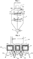
- FIG. 1 is a diagram illustrating an overall configuration of a gas atomize apparatus used as a metal powder producing apparatus according to the present invention.
- the gas atomize apparatus in FIG. 1 includes: a melting chamber 1 housing a crucible (a tundish) 100, see FIG.
- molten metal liquid which is liquid metal
- a gas jet device 200 blowing a high-pressure gas (a gas fluid) against the liquid flowing down from the melting chamber 1 via a liquid nozzle, which is described below, 11 in form of fine particles to pulverize the liquid into a large number of particulates, and spraying the molten metal in form of a liquid
- a jet gas feeding pipe a jet flow feeding pipe 3 through which the high-pressure gas is fed to the gas jet device 200
- a spray chamber 4 which is a container held in an inert gas atmosphere and in which the particulate liquid metal sprayed from the gas jet device 200 is rapidly solidified while falling down
- a hopper 5 provided at a bottom portion of the spray chamber 4 to collect powdery solid metal resulting from solidification during fall-down in the spray chamber 4.
- the gas atomize apparatus uses the gas jet device 200 to jet the gas against the liquid flowing down from the liquid nozzle 11 to produce metal powder.
- the inside of the melting chamber 1 is preferably held in an inert gas atmosphere.
- the spray chamber 4 is a container having, in an upper portion and a middle portion, a cylindrical shape with the same diameter, while having, in a lower portion, a taper shape with a diameter decreasing toward the hopper 5 for easy collection of metal powder in the hopper 5.
- the hopper 5 appropriately discharges an inert gas as exhaust 6.
- FIG. 2 is a cross-sectional view of periphery of the gas jet device 200 of the gas atomize apparatus according to the present embodiment.
- FIG. 3 is a bottom view of the gas jet device 200 according to the present embodiment.
- FIG. 4 is a perspective view of the gas jet device 200 according to the present embodiment. Note that, in FIG. 4 , a plurality of jet holes (through-holes) 92 and 93 included in a second gas jet nozzle 72 and a third gas jet nozzle 73 illustrated in FIG. 3 are omitted.
- a bottom portion of the crucible 100 in the melting chamber 1 is provided with liquid nozzles 11A and 11B which are a plurality of liquid nozzles causing molten metal in the crucible 100 to flow down into the spray chamber 4, the liquid nozzles 11A and 11B protruding downward from a bottom surface of the melting chamber 1 in the vertical direction.
- the two liquid nozzles 11A and 11B may have the same shape and include a vertically long hole which extends in the vertical direction and through which a liquid flows down. The vertically long hole forms a liquid channel through which the molten metal flows downward from the bottom portion of the crucible 100 in the vertical direction.
- Opening ends 21A and 21B positioned at lower ends of the liquid nozzle 11A and the liquid nozzle 11B are each disposed to protrude from a bottom surface of the gas jet device 200 to face a cavity in the spray chamber 4.
- the molten metal in the crucible 100 flows down through the holes inside the liquid nozzles 11A and 11B in form of a liquid flow 8 and is discharged (flows down) into the spray chamber 4 via the opening ends 21A and 21B.
- a value of 5 mm or less which is smaller than that in the related art, can be selected as the minimum inner diameter of the first liquid nozzle 11A and the second liquid nozzle 11B contributing to the size of the diameter of the liquid flow 8 introduced into the spray chamber 4.
- the gas jet device 200 having a generally cylindrical external form, includes a plurality of liquid nozzle insertion holes 12A and 12B into which the plurality of liquid nozzles 11A and 11B are inserted, and a first gas jet nozzle 71 jetting gas against the molten metal flowing down from the liquid nozzles 11A and 11B to pulverize the molten metal.
- the gas jet device 200 has an external shape of a cylinder of a hollow structure filled with an inert high-pressure gas, and internally includes a gas channel 50 forming a gas flow around each of the plurality of liquid nozzle insertion holes 12A and 12B.
- the gas channel 50 is fed with the high-pressure gas from a jet gas feeding pipe 3 connected to a gas suction hole, not illustrated, formed in a side surface of the cylinder of the gas jet device 200. Additionally, the gas jet device 200 supports the crucible 100. Note that, although not illustrated, a heat insulating material is preferably interposed between the melting chamber 1 and the gas jet device 200 to prevent heat transfer from the melting chamber 1.
- the liquid nozzle insertion hole 12A and the liquid nozzle insertion hole 12B are two cylindrical through-holes including axes Cm1 and Cm2 parallel to a center axis Cg0 of the cylindrical gas jet device 200.
- the first liquid nozzle 11A and the second liquid nozzle 11B are respectively inserted into the first liquid nozzle insertion hole 12A and the second liquid nozzle insertion hole 12B.
- the center axes Cm1 and Cm2 of the first liquid nozzle insertion hole 12A and the second liquid nozzle insertion hole 12B may be respectively aligned with the center axes of the holes in the first liquid nozzle 11A and the second liquid nozzle 11B.
- the first gas jet nozzle 71 includes a plurality of jet holes (through-holes) 91 disposed in such a manner as to form first rings, see FIG. 3 , 61 each around a corresponding one of the plurality of liquid nozzle insertion holes 12A and 12B.
- a gas jet nozzle including a plurality of jet holes 91 positioned around the liquid nozzle insertion hole 12A is referred to as a gas jet nozzle 71A
- a gas jet nozzle including a plurality of jet holes 91 positioned around the liquid nozzle insertion hole 12B is referred to as a gas jet nozzle 71B.
- FIG. 5 is a is a diagram illustrating a relationship between gas jet directions of the plurality of jet holes 91 included in the gas jet nozzle 71A and a flow-down area 27 where the liquid from the first liquid nozzle 11A flows down.
- FIG. 5 illustrates, by straight lines 251, gas jet directions of the plurality of jet holes 91 included in the gas jet nozzle 71A.
- Each of the jet holes 91 is formed by drilling, in the bottom surface of the gas jet device 200, a through-hole with a center axis aligned with the corresponding straight line 251.
- the plurality of jet holes 91 are arranged in the bottom surface of the gas jet device 200 at regular intervals on the first ring 61, which is a circle concentric with the center axis Cm1 of the first liquid nozzle insertion hole 12A.
- the gas jet directions, which are illustrated by the straight lines 251, of all the jet holes 91 included in the gas jet nozzle 71A pass through a common focus (a first focus) 261.
- the gas jet directions of all the jet holes 91 concentrate at one point (the focus 261).
- the focus 261 is positioned in a generally cylindrical flow-down area 27 defined by an outer diameter of the molten metal flowing down from the first liquid nozzle 11A, not illustrated in FIG. 4 .
- a dimeter of the flow-down area 27 can be appropriately adjusted according to the minimum inner diameter (an orifice diameter) of a hole included in the first liquid nozzle 11A.
- the diameter of the flow-down area 27 can be set to, for example, a value equal to or smaller than the diameter of the opening end 21A of the first liquid nozzle 11A.
- the gas jet nozzle 71B is formed similarly to the gas jet nozzle 71A, and descriptions of the gas jet nozzle 71B are omitted.
- the first ring 61 is a perfect circle the center of which corresponds to an intersection point between the center axis of each of the liquid nozzle insertion holes 12A and 12B and the bottom surface (the surface facing the inside of the spray chamber 4) of the gas jet device 200.
- the jet holes 91 included in the gas jet nozzle 71A are identical in number to the jet holes 91 included in the gas jet nozzle 71B. However, the number of the jet holes may vary between the gas jet nozzle 71A and the gas jet nozzle 71B.
- the gas jet nozzle 71A and the liquid nozzle 11A are included in a first spray nozzle 20A spraying the molten metal into the spray chamber 4 in form of a liquid, and the gas jet nozzle 71B and the liquid nozzle 11B are similarly included in a second spray nozzle 20B. That is, the gas atomize apparatus according to the present embodiment includes two spray nozzles of the first spray nozzle 20A and the second spray nozzle 20B.
- the gas jet device 200 includes a second gas jet nozzle 72 and a third gas jet nozzle 73 provided at the bottom surface of the gas jet device 200, and a fourth gas jet nozzle 74, see FIG. 1 , provided at an inner wall surface of the spray chamber 4, in addition to the first gas jet nozzle 71 described above.
- Second Gas Jet Nozzle 72 Including 72A and 72B
- the second gas jet nozzle 72 is a gas jet nozzle including a plurality of jet holes (through-holes) 92 disposed in the bottom surface of the gas jet device 200 in such a manner as to form second rings 62 each on an outer side of a corresponding one of the two first rings 61.
- the second gas jet nozzle 72 jets gas to prevent scatter of metal particles resulting from pulverization by the first gas jet nozzle 71.
- the plurality of jet holes 92 are drilled in the bottom surface of the gas jet device 200.
- a gas jet nozzle including the plurality of jet holes 92 positioned around the liquid nozzle insertion hole 12A is referred to as a first gas jet nozzle 72A
- a gas jet nozzle including the plurality of jet holes 92 positioned around the liquid nozzle insertion hole 12B is referred to as a second gas jet nozzle 72B.
- FIG. 6 is a diagram illustrating a relationship between gas jet directions of the plurality of jet holes 92 included in the gas jet nozzle 72A and the focus (the first focus) 261 of the gas jet nozzle 71A.
- FIG. 6 illustrates, by straight lines 252, gas jet directions of the plurality of jet holes 92 included in the gas jet nozzle 72A.
- Each of the jet holes 92 is formed by drilling, in the bottom surface of the gas jet device 200, a through-hole with a center axis aligned with the corresponding straight line 252.
- the plurality of jet holes 92 are arranged in the bottom surface of the gas jet device 200 at regular intervals on the second ring 62, which is a circle concentric with the center axis Cm1 of the first liquid nozzle insertion hole 12A.
- the gas jet directions, which are illustrated by the straight lines 252, of all the jet holes 92 included in the gas jet nozzle 72A pass through a common focus (a second focus) 262.
- the gas jet directions of all the jet holes 92 concentrate at one point (the focus 262).
- the focus (the second focus) 262 is positioned below the focus (the first focus) 261 of the gas jet nozzle 71A.
- the gas jet nozzle 72B is formed similarly to the gas jet nozzle 72A, and descriptions of the gas jet nozzle 72B are omitted.
- the second ring 62 is a perfect circle the center of which corresponds to an intersection point between the center axis of each of the liquid nozzle insertion holes 12A and 12B and the bottom surface (the surface facing the inside of the spray chamber 4) of the gas jet device 200 but that the second ring 62 may be an ellipse or a polygon and the center may be misaligned with the center axis of each of the liquid nozzle insertion holes 12A and 12B.
- the second ring 62 and the jet directions 252 of the plurality of jet holes 92 disposed on the second ring 62 need to be set such that the focus (the second focus) 262 of the jet holes 92 is positioned below the first focus 261. Additionally, in FIG.
- the jet holes 92 included in the gas jet nozzle 72A are identical in number to the jet holes 92 included in the gas jet nozzle 72B. However, the number of the jet holes may vary between the gas jet nozzle 72A and the gas jet nozzle 72B. Additionally, in FIG. 6 , the jet holes 92 included in the gas jet nozzle 72A are identical in number to the jet holes 91 included in the gas jet nozzle 71A. However, the number of the jet holes may vary between the gas jet nozzle 72A and the gas jet nozzle 71A.
- the third gas jet nozzle 73 is a gas jet nozzle including a plurality of jet holes (through-holes) 93 disposed in the bottom surface of the gas jet device 200 in such a manner as to form a third ring 63 on an outer side of the second gas jet nozzle 72, which is disposed on the two second rings 62, and jetting gas against the inner wall surface of the spray chamber 4.
- the plurality of jet holes 93 are arranged in the bottom surface of the gas jet device 200 at regular intervals on the third ring 63 centered at a point through which the center axis Cg0 of the gas jet device 200 passes.
- FIG. 2 and FIG. 3 illustrate, by an arrow 253, a gas jet direction of one of the jet holes 93 included in the gas jet nozzle 73.
- the gas jet direction (the straight line 253) of each jet hole 93 extends toward a closest portion of the inner wall surface of the spray chamber 4.
- Vectors resulting from projection of the gas jet directions 253 according to the present embodiment on the gas jet device 200 radially extend outward from the center, which is a point through which the center axis Cg0 of the gas jet device 200 passes on the bottom surface of the gas jet device 200, of the third ring 63.
- FIG. 3 illustrates the gas jet direction 253 of one of the plurality of jet holes 93.
- Each of the jet holes 93 is formed by drilling, in the bottom surface of the gas jet device 200, a through-hole with a center axis aligned with the corresponding straight line 253.
- the third ring 63 is a perfect circle the center of which corresponds to the point through which the center axis Cg0 of the gas jet device 200 passes on the bottom surface of the gas jet device 200, but that the third ring 63 may be an ellipse or a polygon and the center may be misaligned with the center axis Cg0 of the gas jet device 200.
- the third ring 63 and the axial directions 253 of the jet holes 93 need to be set such that the gas jet direction of gas jetted from each jet hole 92 extends toward the inner wall surface of the spray chamber 4.
- the number of the jet holes 93 illustrated in FIG. 3 is only an example and that any number can be selected to the extent that cooling performance of the spray chamber 4 is not degraded.
- the fourth gas jet nozzle 74 is a gas jet nozzle including a plurality of jet holes 94 disposed at a predetermined height in the spray chamber 4 and jetting gas along the inner wall surface of the spray chamber 4 to generate, in the spray chamber 4, a swirling flow 81 around the center axis Cg0 of the spray chamber 4.
- two gas jet nozzles 74A and 74B are provided at different installation heights in the spray chamber 4.
- a gas jet nozzle provided at a relatively high position in a height direction in the spray chamber 4 is referred to as a gas jet nozzle 74A
- a gas jet nozzle provided at a relatively low position in the height direction in the spray chamber 4 is referred to as a gas jet nozzle 74B.
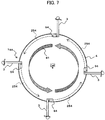
- FIG. 7 is a cross-sectional view of the spray chamber 4 taken along line VII-VII in FIG. 1 and illustrating a configuration of the gas jet nozzle 74A and the jet holes 94 included in the gas jet nozzle 74A.
- FIG. 7 illustrates, by arrows 254, a flow of gas jetted from the plurality of jet holes included in the gas jet nozzle 74A.
- Each of the jet holes 94 is formed using a pipe with a center axis aligned with a tangential direction in an axial cross section of the inner wall surface of the spray chamber 4. As illustrated in FIG. 7 , the plurality of jet holes 94 are arranged at regular intervals in a circumferential direction of an inner circumferential surface of the spray chamber 4.
- Each of the plurality of jet holes 94 is connected to the jet gas feeding pipe (the jet fluid feeding pipe) 3 and fed with a high-pressure gas from the jet gas feeding pipe 3.
- the four jet holes 94 are disposed at intervals of 90 degrees on the same plane but that the number of the jet holes 94 may have any other value as long as the jet holes 94 enable the swirling flow 81 to be generated.
- the gas jet nozzle 74B is formed similarly to the gas jet nozzle 74A, and descriptions of the gas jet nozzle 74B are omitted.
- the high-pressure gas under the same pressure is jetted from all of the jet holes 91 included in the first gas jet nozzles 71A and 71B toward the inside of the spray chamber 4 in the gas jet device 200 while following jet directions, which are illustrated by the straight lines 251 as seen in FIG. 5 , preset for the respective jet holes 91.
- the gas is concentrically jetted onto the focus (the first focus) 261, forming fluid membranes 101 each having an inverted conical shape with a vertex corresponding to the focus 261 and a bottom surface corresponding to the circle (the ring) 61 on which the plurality of jet holes 91 are disposed as illustrated in FIG. 5 .
- the fluid membranes 101 may be referred to as metal spraying gas jets (first gas jets) 101.
- feeding molten metal into the melting chamber 1 causes two liquid flows 8 to flow down into the spray chamber 4 via the plurality of liquid nozzles 11A and 11B provided at the bottom surface of the melting chamber 1. Then, the liquid flows 8 collide with the metal spray gas jets 101 formed by the high-pressure gas near the two focuses 261 related to the first gas jet nozzles 71A and 71B and are pulverized into a large number of particulates 15.
- a value, for example, 1 to 2 mm, smaller than a corresponding value, for example, approximately 5 mm, in the related art is selected as the minimum inner diameter of the holes included in the two liquid nozzles 11A and 11B.
- the single spray chamber 4 includes the two liquid nozzles 11A and 11B, that is, the two spray nozzles 20A and 20B, enabling the yield per unit time to be doubled.
- the high-pressure gas under the same pressure is jetted from all of the jet holes 92 included in the second gas jet nozzles 72A and 72B toward the inside of the spray chamber 4 in the gas jet device 200 while following jet directions, which are illustrated by the straight lines 252 as seen in FIG. 6 , preset for the respective jet holes 92.
- the gas is concentrically jetted onto the focus (the second focus) 262, forming fluid membranes 102 each having an inverted conical shape with a vertex corresponding to the focus 262 and a bottom surface corresponding to the circle (the ring) 62 on which the plurality of jet holes 92 are disposed as illustrated in FIG. 6 .
- the fluid membranes 102 may be referred to as contact preventing gas jets (second gas jets) 102.
- the contact preventing gas jets 102 formed by the second gas jet nozzles 72A and 72B function as air curtains preventing particulates 15, for example, molten metal flowing down from the liquid nozzle 11A, atomized from one of the two spray nozzles 20A and 20B from colliding with particulates 15, for example, molten metal flowing down from the liquid nozzle 11B, atomized from the other spray nozzle.
- this configuration prevents the metal particles from being deformed, allowing improvement of production efficiency for metal powder compared to a configuration provided only with the spray nozzles 20A and 20B.
- the metal powder producing apparatus includes the two spray nozzles 20A and 20B in the single spray chamber 4 and has a shorter distance from each of the spray nozzles 20A and 20B to the inner wall surface of the spray chamber 4 than metal powder producing apparatuses in the related art including only one spray nozzle 20.
- unsolidified metal powder 15 is likely to collide with and adhere to the inner wall surface of the spray chamber 4.
- the contact preventing gas jets (the second gas jets) 102 formed by the second gas jet nozzle 72 according to the present embodiment have generally conical shapes externally covering the metal spraying gas jets (the first gas jets) 101 and can thus inhibit the particulates 15 from scattering toward the inner wall surface of the spray chamber 4. That is, according to the present embodiment, this configuration also allows improvement of the production efficiency for metal powder. Additionally, for example, even in a case where the spray chamber 4 utilized has the same diameter as that in the related art, collision of the particulates 15 can be prevented, thus allowing prevention of an increase in the replacement cost of the spray chamber 4 and in the size of an installation space for the spray chamber 4.
- the particulates 15 into which the metal has been formed by the jet gas from the first gas jet nozzle 71 and which are inhibited by the jet gas from the second gas jet nozzle 72 from scattering in a radial direction of the spray chamber 4 are rapidly cooled and solidified while falling down through the spray chamber 4 and collected in the hopper 5 in form of a large number of grains of metal powder.
- the high-pressure gas under the same pressure is jetted from all of the jet holes 93 included in the third gas jet nozzle 73 toward the inner wall of the spray chamber 4 in the gas jet device 200 while following jet directions, which are illustrated by straight lines 253 as seen in FIG. 3 , preset for the respective jet holes 93.
- the gas is jetted from each jet hole 93 to the closest portion of the inner wall surface of the spray chamber 4, forming a fluid membrane 103 having a generally truncated conical shape as illustrated in FIG. 2 .
- the fluid membrane 103 may be referred to as a spray chamber cooling gas jet (a third gas jet) 103.
- the spray chamber cooling gas jet 103 formed by the third gas jet nozzle 73 is discharged to the inner wall surface of the spray chamber 4 to cool the spray chamber 4. This facilitates sufficient cooling, in the spray chamber 4, of the particulates (the metal powder) 15 atomized by the spray nozzles 20A and 20B, and the particulates 15 are inhibited from sticking to and accumulating in the hopper 5 without being solidified in the spray chamber 4, leading to a reduced yield. Additionally, like the contact preventing gas jets 102, the spray chamber cooling gas jet 103 provides a function to prevent the particulates 15 from colliding with the inner wall surface of the spray chamber 4. That is, according to the present embodiment, this configuration also allows improvement of the production efficiency for metal powder.
- feeding a high-pressure gas to the fourth gas jet nozzle 74 including 74A and 74B causes the high-pressure gas under the same pressure to be jetted from all of the jet holes 94 included in the fourth gas jet nozzle 74 along the inner wall of the spray chamber 4 while following jet directions, for example, the tangential direction of the inner wall of the spray chamber 4 in FIG. 7 , preset for the respective jet holes 94.
- flows of the gas as indicated by the arrows 254 in FIG. 7 are generated in the spray chamber 4, and as a result, the swirling flow 81 along the inner wall of the spray chamber 4 is generated around the center axis of the spray chamber 4.
- the swirling flow 81 provides a function to prevent the particulates 15 from colliding with the inner wall surface. Additionally, the swirling flow 81 exerts an effect of uniformizing a heat distribution in a horizontal plane of the spray chamber 4, and thus allows the cooling performance of the spray chamber 4 to be improved in synergy with the third gas jet 103. That is, according to the present embodiment, this configuration also allows improvement of the production efficiency for metal powder.
- the metal spray apparatus including the second, third, and fourth gas jet nozzles 72, 73, and 74 in addition to the first gas jet nozzle 71, fine metal powder can be efficiently produced without any change in the shape of the spray chamber.
- the present invention is not limited to the above-described embodiment and includes various modifications without departing the spirits of the present invention.
- the present invention is not limited to the configuration including all of the components described above in the embodiment but includes the configuration partly deleted. Additionally, a part of the configuration according to one embodiment can be added to or replace the configuration according to another embodiment.
- the gas channel 50 in the gas jet device 200 may be separated into portions corresponding to the respective gas jet nozzles 71 to 73, and may feed gas under different pressures to a plurality of gas channels into which the gas channel 50 has been separated, thus varying or adjusting the pressures of the gas jetted from the gas jet nozzles 71 to 73.
- the gas jet nozzles 71 to 74 may have appropriately different diameters.
- the second to fourth gas jet nozzles 72 to 74 are provided in addition to the first gas jet nozzle 71.
- an embodiment including at least one of the second to fourth gas jet nozzles 72 to 74 may produce the effect of improving the production efficiency for metal powder.
- the fourth gas jet nozzle 74 is configured to generate the swirling flow 81 counterclockwise in FIG. 7 . However, the directions of the jet holes 94 may be changed to allow generation of a clockwise swirling flow 81. Additionally, the fourth gas jet nozzle 74 is provided at two positions in the height direction in the spray chamber 4. However, the fourth gas jet nozzle 74 may be provided at one or three or more positions.
- the two spray nozzles 20A and 20B are provided for the single spray chamber.
- the number of the gas jet nozzles may be reduced to one or increased to three or more.
- gas or gas fluid
- a liquid such as water may be jetted. That is, the present invention is applicable to any nozzles as long as the nozzle jets a fluid.
Landscapes
- Manufacture Of Metal Powder And Suspensions Thereof (AREA)
- Nozzles (AREA)
Abstract
Description
- The present invention relates to a metal powder producing apparatus producing particulate metal (metal powder) by causing a high-pressure gas fluid to collide with molten metal flowing down from a liquid nozzle, and a gas jet device for the metal powder producing apparatus.
- Examples of a method for producing particulate metal (metal powder) from molten metal include atomization including gas atomization and water atomization. The gas atomization involves causing a liquid to flow down from a liquid nozzle provided at a lower portion of a melting chamber in which molten metal is stored and blowing, against the liquid, an inert gas from a plurality of gas jet nozzles disposed around the liquid nozzle. A flow of the molten metal from the liquid nozzle is split into a large number of fine metal droplets by inert gas flows from the gas jet nozzles, and the metal droplets fall down through a spray chamber and are solidified while being spheroidized by surface tension. Thus, spherical grains of metal powder are collected in a hopper at a bottom portion of the spray chamber.
- For example,
JP-2016-211027-A - In recent years, there has been an increasing need for metal powder having a smaller particle size than metal powder previously required for the atomization, for example, as a material for metal three-dimensional printers accumulating a large amount of metal particles to form metal with a desired shape. The known metal powder used for powder metallurgy, welding, and the like has a particle size of, for example, approximately 70 to 100 µm. However, the metal powder used for three-dimensional printers has a very small particle size of, for example, approximately 20 to 50 µm.
- In this regard, a "spray nozzle" is a generic term used to refer to a liquid nozzle and a gas jet nozzle including a plurality of jet holes formed around the liquid nozzle and jetting gas from the plurality of jet holes to pulverize a liquid flowing down from the liquid nozzle. A possible measure for efficiently producing fine metal powder without any change in the shape of the known spray chamber is to provide a plurality of spray nozzles for one spray chamber, otherwise one spray nozzle is provided for one spray chamber.
- However, thus providing a plurality of spray nozzles may bring metal particles resulting from pulverization by the spray nozzles into contact with one another before the metal particles are solidified, increasing the particle size of each metal particle. Thus, the yield of metal particles having the desired particle size may decrease. Additionally, providing the plurality of spray nozzles makes a distance from each spray nozzle (liquid nozzle) to an inner wall of the spray chamber shorter than in the related art. Accordingly, unsolidified metal particles may come into contact with or stick to the inner wall of the spray chamber, and the yield is likely to decrease. Furthermore, in a case where the metal particle sticks to or accumulates on the inner wall of the spray chamber to degrade heat radiation performance of the spray chamber, the metal powder sticks to or accumulates in the hopper without being sufficiently cooled in the spray chamber. This may reduce the yield.
- An object of the present invention is to provide a metal powder producing apparatus capable of efficiently producing meal powder without any change the shape of the spray chamber and a gas jet device for the metal powder producing apparatus.
- The present invention includes a plurality of aspects for solving the above-described problem. An example of the aspects includes a metal powder producing apparatus including: a spray chamber; a plurality of liquid nozzles causing molten metal stored in a crucible to flow down into the spray chamber; a gas jet device provided with a plurality of liquid nozzle insertion holes into each of which respective of the plurality of liquid nozzles are inserted; a first gas jet nozzle including a plurality of jet holes disposed in a bottom surface of the gas jet device in such a manner as to form first rings each around a corresponding one of the plurality of liquid nozzle insertion holes, the first gas jet nozzle jetting gas against molten metal flowing down from the liquid nozzles to pulverize the molten metal; a second gas jet nozzle including a plurality of jet holes disposed in the bottom surface of the gas jet device in such a manner as to form second rings each on an outer side of a corresponding one of the first rings, the second gas jet nozzle jetting gas to prevent scatter of metal particles resulting from pulverization by the first gas jet nozzle; and/or a third gas jet nozzle including a plurality of jet holes disposed in the bottom surface of the gas jet device in such a manner as to form a third ring on an outer side of the second gas jet nozzle, the third gas jet nozzle jetting gas against an inner wall surface of the spray chamber.
- According to the aspects of the present invention, fine metal powder can be efficiently produced without any change in the shape of the spray chamber.
-
-
FIG. 1 is a diagram illustrating an overall configuration of a gas atomize apparatus used as a metal powder producing apparatus; -
FIG. 2 is a cross-sectional view of periphery of agas jet device 200; -
FIG. 3 is a bottom view of thegas jet device 200; -
FIG. 4 is a perspective view of thegas jet device 200; -
FIG. 5 is a diagram illustrating a relationship between gas jet directions of a plurality ofjet holes 91 included in agas jet nozzle 71A and a flow-downarea 27 where a liquid from a first liquid nozzle 11a flows down; -
FIG. 6 is a diagram illustrating a relationship between gas jet directions of a plurality ofjet holes 92 included in agas jet nozzle 72A and a focus (a first focus) 261 of thegas jet nozzle 71A; and -
FIG. 7 is a cross-sectional view of aspray chamber 4 taken along line VII-VII inFIG. 1 . - An embodiment of the present invention will be described using the drawings.
-
FIG. 1 is a diagram illustrating an overall configuration of a gas atomize apparatus used as a metal powder producing apparatus according to the present invention. The gas atomize apparatus inFIG. 1 includes: a melting chamber 1 housing a crucible (a tundish) 100, seeFIG. 2 , in which molten metal (liquid) which is liquid metal, is stored; agas jet device 200 blowing a high-pressure gas (a gas fluid) against the liquid flowing down from the melting chamber 1 via a liquid nozzle, which is described below, 11 in form of fine particles to pulverize the liquid into a large number of particulates, and spraying the molten metal in form of a liquid; a jet gas feeding pipe (a jet flow feeding pipe) 3 through which the high-pressure gas is fed to thegas jet device 200; aspray chamber 4 which is a container held in an inert gas atmosphere and in which the particulate liquid metal sprayed from thegas jet device 200 is rapidly solidified while falling down; and ahopper 5 provided at a bottom portion of thespray chamber 4 to collect powdery solid metal resulting from solidification during fall-down in thespray chamber 4. The gas atomize apparatus uses thegas jet device 200 to jet the gas against the liquid flowing down from the liquid nozzle 11 to produce metal powder. - The inside of the melting chamber 1 is preferably held in an inert gas atmosphere. The
spray chamber 4 is a container having, in an upper portion and a middle portion, a cylindrical shape with the same diameter, while having, in a lower portion, a taper shape with a diameter decreasing toward thehopper 5 for easy collection of metal powder in thehopper 5. Thehopper 5 appropriately discharges an inert gas asexhaust 6. -
FIG. 2 is a cross-sectional view of periphery of thegas jet device 200 of the gas atomize apparatus according to the present embodiment.FIG. 3 is a bottom view of thegas jet device 200 according to the present embodiment.FIG. 4 is a perspective view of thegas jet device 200 according to the present embodiment. Note that, inFIG. 4 , a plurality of jet holes (through-holes) 92 and 93 included in a secondgas jet nozzle 72 and a thirdgas jet nozzle 73 illustrated inFIG. 3 are omitted. - As illustrated in
FIG. 2 , a bottom portion of thecrucible 100 in the melting chamber 1 is provided withliquid nozzles crucible 100 to flow down into thespray chamber 4, theliquid nozzles liquid nozzles crucible 100 in the vertical direction. -
Opening ends liquid nozzle 11A and theliquid nozzle 11B are each disposed to protrude from a bottom surface of thegas jet device 200 to face a cavity in thespray chamber 4. The molten metal in thecrucible 100 flows down through the holes inside theliquid nozzles liquid flow 8 and is discharged (flows down) into thespray chamber 4 via theopening ends liquid nozzle 11A and the secondliquid nozzle 11B contributing to the size of the diameter of theliquid flow 8 introduced into thespray chamber 4. - As illustrated in
FIG. 2 , thegas jet device 200, having a generally cylindrical external form, includes a plurality of liquidnozzle insertion holes liquid nozzles gas jet nozzle 71 jetting gas against the molten metal flowing down from theliquid nozzles gas jet device 200 has an external shape of a cylinder of a hollow structure filled with an inert high-pressure gas, and internally includes agas channel 50 forming a gas flow around each of the plurality of liquidnozzle insertion holes gas channel 50 is fed with the high-pressure gas from a jetgas feeding pipe 3 connected to a gas suction hole, not illustrated, formed in a side surface of the cylinder of thegas jet device 200. Additionally, thegas jet device 200 supports thecrucible 100. Note that, although not illustrated, a heat insulating material is preferably interposed between the melting chamber 1 and thegas jet device 200 to prevent heat transfer from the melting chamber 1. - As illustrated in
FIG. 4 , the liquidnozzle insertion hole 12A and the liquidnozzle insertion hole 12B are two cylindrical through-holes including axes Cm1 and Cm2 parallel to a center axis Cg0 of the cylindricalgas jet device 200. The firstliquid nozzle 11A and the secondliquid nozzle 11B are respectively inserted into the first liquidnozzle insertion hole 12A and the second liquidnozzle insertion hole 12B. The center axes Cm1 and Cm2 of the first liquidnozzle insertion hole 12A and the second liquidnozzle insertion hole 12B may be respectively aligned with the center axes of the holes in the firstliquid nozzle 11A and the secondliquid nozzle 11B. - The first
gas jet nozzle 71 includes a plurality of jet holes (through-holes) 91 disposed in such a manner as to form first rings, seeFIG. 3 , 61 each around a corresponding one of the plurality of liquidnozzle insertion holes gas jet nozzle 71, a gas jet nozzle including a plurality of jet holes 91 positioned around the liquidnozzle insertion hole 12A is referred to as agas jet nozzle 71A, and a gas jet nozzle including a plurality of jet holes 91 positioned around the liquidnozzle insertion hole 12B is referred to as agas jet nozzle 71B. -
FIG. 5 is a is a diagram illustrating a relationship between gas jet directions of the plurality of jet holes 91 included in thegas jet nozzle 71A and a flow-down area 27 where the liquid from the firstliquid nozzle 11A flows down. -
FIG. 5 illustrates, bystraight lines 251, gas jet directions of the plurality of jet holes 91 included in thegas jet nozzle 71A. Each of the jet holes 91 is formed by drilling, in the bottom surface of thegas jet device 200, a through-hole with a center axis aligned with the correspondingstraight line 251. The plurality of jet holes 91 are arranged in the bottom surface of thegas jet device 200 at regular intervals on thefirst ring 61, which is a circle concentric with the center axis Cm1 of the first liquidnozzle insertion hole 12A. The gas jet directions, which are illustrated by thestraight lines 251, of all the jet holes 91 included in thegas jet nozzle 71A pass through a common focus (a first focus) 261. That is, the gas jet directions of all the jet holes 91 concentrate at one point (the focus 261). Thefocus 261 is positioned in a generally cylindrical flow-down area 27 defined by an outer diameter of the molten metal flowing down from the firstliquid nozzle 11A, not illustrated inFIG. 4 . A dimeter of the flow-down area 27 can be appropriately adjusted according to the minimum inner diameter (an orifice diameter) of a hole included in the firstliquid nozzle 11A. The diameter of the flow-down area 27 can be set to, for example, a value equal to or smaller than the diameter of the openingend 21A of the firstliquid nozzle 11A. Thegas jet nozzle 71B is formed similarly to thegas jet nozzle 71A, and descriptions of thegas jet nozzle 71B are omitted. - Note that the
first ring 61 according to the present embodiment is a perfect circle the center of which corresponds to an intersection point between the center axis of each of the liquidnozzle insertion holes gas jet device 200. InFIG. 3 , the jet holes 91 included in thegas jet nozzle 71A are identical in number to the jet holes 91 included in thegas jet nozzle 71B. However, the number of the jet holes may vary between thegas jet nozzle 71A and thegas jet nozzle 71B. - The
gas jet nozzle 71A and theliquid nozzle 11A are included in afirst spray nozzle 20A spraying the molten metal into thespray chamber 4 in form of a liquid, and thegas jet nozzle 71B and theliquid nozzle 11B are similarly included in asecond spray nozzle 20B. That is, the gas atomize apparatus according to the present embodiment includes two spray nozzles of thefirst spray nozzle 20A and thesecond spray nozzle 20B. - The
gas jet device 200 according to the present embodiment includes a secondgas jet nozzle 72 and a thirdgas jet nozzle 73 provided at the bottom surface of thegas jet device 200, and a fourth gas jet nozzle 74, seeFIG. 1 , provided at an inner wall surface of thespray chamber 4, in addition to the firstgas jet nozzle 71 described above. - The second
gas jet nozzle 72 is a gas jet nozzle including a plurality of jet holes (through-holes) 92 disposed in the bottom surface of thegas jet device 200 in such a manner as to form second rings 62 each on an outer side of a corresponding one of the twofirst rings 61. The secondgas jet nozzle 72 jets gas to prevent scatter of metal particles resulting from pulverization by the firstgas jet nozzle 71. The plurality of jet holes 92 are drilled in the bottom surface of thegas jet device 200. In this case, in the secondgas jet nozzle 72, a gas jet nozzle including the plurality of jet holes 92 positioned around the liquidnozzle insertion hole 12A is referred to as a firstgas jet nozzle 72A, and a gas jet nozzle including the plurality of jet holes 92 positioned around the liquidnozzle insertion hole 12B is referred to as a secondgas jet nozzle 72B. -
FIG. 6 is a diagram illustrating a relationship between gas jet directions of the plurality of jet holes 92 included in thegas jet nozzle 72A and the focus (the first focus) 261 of thegas jet nozzle 71A. -
FIG. 6 illustrates, bystraight lines 252, gas jet directions of the plurality of jet holes 92 included in thegas jet nozzle 72A. Each of the jet holes 92 is formed by drilling, in the bottom surface of thegas jet device 200, a through-hole with a center axis aligned with the correspondingstraight line 252. The plurality of jet holes 92 are arranged in the bottom surface of thegas jet device 200 at regular intervals on thesecond ring 62, which is a circle concentric with the center axis Cm1 of the first liquidnozzle insertion hole 12A. The gas jet directions, which are illustrated by thestraight lines 252, of all the jet holes 92 included in thegas jet nozzle 72A pass through a common focus (a second focus) 262. That is, the gas jet directions of all the jet holes 92 concentrate at one point (the focus 262). The focus (the second focus) 262 is positioned below the focus (the first focus) 261 of thegas jet nozzle 71A. Thegas jet nozzle 72B is formed similarly to thegas jet nozzle 72A, and descriptions of thegas jet nozzle 72B are omitted. - Note that the
second ring 62 according to the present embodiment is a perfect circle the center of which corresponds to an intersection point between the center axis of each of the liquidnozzle insertion holes gas jet device 200 but that thesecond ring 62 may be an ellipse or a polygon and the center may be misaligned with the center axis of each of the liquidnozzle insertion holes second ring 62 and thejet directions 252 of the plurality of jet holes 92 disposed on thesecond ring 62 need to be set such that the focus (the second focus) 262 of the jet holes 92 is positioned below thefirst focus 261. Additionally, inFIG. 3 , the jet holes 92 included in thegas jet nozzle 72A are identical in number to the jet holes 92 included in thegas jet nozzle 72B. However, the number of the jet holes may vary between thegas jet nozzle 72A and thegas jet nozzle 72B. Additionally, inFIG. 6 , the jet holes 92 included in thegas jet nozzle 72A are identical in number to the jet holes 91 included in thegas jet nozzle 71A. However, the number of the jet holes may vary between thegas jet nozzle 72A and thegas jet nozzle 71A. - The third
gas jet nozzle 73 is a gas jet nozzle including a plurality of jet holes (through-holes) 93 disposed in the bottom surface of thegas jet device 200 in such a manner as to form athird ring 63 on an outer side of the secondgas jet nozzle 72, which is disposed on the twosecond rings 62, and jetting gas against the inner wall surface of thespray chamber 4. The plurality of jet holes 93 are arranged in the bottom surface of thegas jet device 200 at regular intervals on thethird ring 63 centered at a point through which the center axis Cg0 of thegas jet device 200 passes. -
FIG. 2 andFIG. 3 illustrate, by anarrow 253, a gas jet direction of one of the jet holes 93 included in thegas jet nozzle 73. The gas jet direction (the straight line 253) of eachjet hole 93 extends toward a closest portion of the inner wall surface of thespray chamber 4. Vectors resulting from projection of thegas jet directions 253 according to the present embodiment on thegas jet device 200 radially extend outward from the center, which is a point through which the center axis Cg0 of thegas jet device 200 passes on the bottom surface of thegas jet device 200, of thethird ring 63.FIG. 3 illustrates thegas jet direction 253 of one of the plurality of jet holes 93. Each of the jet holes 93 is formed by drilling, in the bottom surface of thegas jet device 200, a through-hole with a center axis aligned with the correspondingstraight line 253. - Note that the
third ring 63 according to the present embodiment is a perfect circle the center of which corresponds to the point through which the center axis Cg0 of thegas jet device 200 passes on the bottom surface of thegas jet device 200, but that thethird ring 63 may be an ellipse or a polygon and the center may be misaligned with the center axis Cg0 of thegas jet device 200. However, thethird ring 63 and theaxial directions 253 of the jet holes 93 need to be set such that the gas jet direction of gas jetted from eachjet hole 92 extends toward the inner wall surface of thespray chamber 4. Note that the number of the jet holes 93 illustrated inFIG. 3 is only an example and that any number can be selected to the extent that cooling performance of thespray chamber 4 is not degraded. - As illustrated in
FIG. 1 , the fourth gas jet nozzle 74 is a gas jet nozzle including a plurality of jet holes 94 disposed at a predetermined height in thespray chamber 4 and jetting gas along the inner wall surface of thespray chamber 4 to generate, in thespray chamber 4, a swirlingflow 81 around the center axis Cg0 of thespray chamber 4. In the present embodiment, as illustrated inFIG. 1 , twogas jet nozzles spray chamber 4. In this case, in the fourth gas jet nozzle 74, a gas jet nozzle provided at a relatively high position in a height direction in thespray chamber 4 is referred to as agas jet nozzle 74A, and a gas jet nozzle provided at a relatively low position in the height direction in thespray chamber 4 is referred to as agas jet nozzle 74B. -
FIG. 7 is a cross-sectional view of thespray chamber 4 taken along line VII-VII inFIG. 1 and illustrating a configuration of thegas jet nozzle 74A and the jet holes 94 included in thegas jet nozzle 74A.FIG. 7 illustrates, byarrows 254, a flow of gas jetted from the plurality of jet holes included in thegas jet nozzle 74A. Each of the jet holes 94 is formed using a pipe with a center axis aligned with a tangential direction in an axial cross section of the inner wall surface of thespray chamber 4. As illustrated inFIG. 7 , the plurality of jet holes 94 are arranged at regular intervals in a circumferential direction of an inner circumferential surface of thespray chamber 4. Each of the plurality of jet holes 94 is connected to the jet gas feeding pipe (the jet fluid feeding pipe) 3 and fed with a high-pressure gas from the jetgas feeding pipe 3. Note that, in the example inFIG. 7 , the fourjet holes 94 are disposed at intervals of 90 degrees on the same plane but that the number of the jet holes 94 may have any other value as long as the jet holes 94 enable the swirlingflow 81 to be generated. Additionally, thegas jet nozzle 74B is formed similarly to thegas jet nozzle 74A, and descriptions of thegas jet nozzle 74B are omitted. - In the metal powder producing apparatus configured as described above, in a case where a high-pressure gas is fed through the jet
gas feeding pipe 3 to thegas jet device 200, the high-pressure gas under the same pressure is jetted from all of the jet holes 91 included in the firstgas jet nozzles spray chamber 4 in thegas jet device 200 while following jet directions, which are illustrated by thestraight lines 251 as seen inFIG. 5 , preset for the respective jet holes 91. At this time, in the firstgas jet nozzles fluid membranes 101 each having an inverted conical shape with a vertex corresponding to thefocus 261 and a bottom surface corresponding to the circle (the ring) 61 on which the plurality of jet holes 91 are disposed as illustrated inFIG. 5 . Thefluid membranes 101 may be referred to as metal spraying gas jets (first gas jets) 101. - On the other hand, feeding molten metal into the melting chamber 1 causes two
liquid flows 8 to flow down into thespray chamber 4 via the plurality ofliquid nozzles spray gas jets 101 formed by the high-pressure gas near the twofocuses 261 related to the firstgas jet nozzles particulates 15. - In the present embodiment, a value, for example, 1 to 2 mm, smaller than a corresponding value, for example, approximately 5 mm, in the related art is selected as the minimum inner diameter of the holes included in the two
liquid nozzles gas jet nozzles spray chamber 4 is prevented. This eliminates a need to replace thespray chamber 4 with one having a larger diameter or a need to enlarge an installation space in thespray chamber 4 in order to prevent the metal particles from being deformed. On the other hand, the minimum inner diameter smaller than that in the related art reduces the flow rate of theliquid flow 8 per unit time for each of theliquid nozzles single spray chamber 4 includes the twoliquid nozzles spray nozzles - Additionally, as is the case with the first
gas jet nozzle 71, in a case where a high-pressure gas is fed through the jetgas feeding pipe 3 to thegas jet device 200, the high-pressure gas under the same pressure is jetted from all of the jet holes 92 included in the secondgas jet nozzles spray chamber 4 in thegas jet device 200 while following jet directions, which are illustrated by thestraight lines 252 as seen inFIG. 6 , preset for the respective jet holes 92. At this time, in the secondgas jet nozzles fluid membranes 102 each having an inverted conical shape with a vertex corresponding to thefocus 262 and a bottom surface corresponding to the circle (the ring) 62 on which the plurality of jet holes 92 are disposed as illustrated inFIG. 6 . Thefluid membranes 102 may be referred to as contact preventing gas jets (second gas jets) 102. - The contact preventing
gas jets 102 formed by the secondgas jet nozzles curtains preventing particulates 15, for example, molten metal flowing down from theliquid nozzle 11A, atomized from one of the twospray nozzles particulates 15, for example, molten metal flowing down from theliquid nozzle 11B, atomized from the other spray nozzle. As a result, this configuration prevents the metal particles from being deformed, allowing improvement of production efficiency for metal powder compared to a configuration provided only with thespray nozzles - Additionally, the metal powder producing apparatus according to the present embodiment includes the two
spray nozzles single spray chamber 4 and has a shorter distance from each of thespray nozzles spray chamber 4 than metal powder producing apparatuses in the related art including only one spray nozzle 20. Thus, in the metal powder producing apparatus according to the present embodiment,unsolidified metal powder 15 is likely to collide with and adhere to the inner wall surface of thespray chamber 4. In this regard, the contact preventing gas jets (the second gas jets) 102 formed by the secondgas jet nozzle 72 according to the present embodiment have generally conical shapes externally covering the metal spraying gas jets (the first gas jets) 101 and can thus inhibit theparticulates 15 from scattering toward the inner wall surface of thespray chamber 4. That is, according to the present embodiment, this configuration also allows improvement of the production efficiency for metal powder. Additionally, for example, even in a case where thespray chamber 4 utilized has the same diameter as that in the related art, collision of theparticulates 15 can be prevented, thus allowing prevention of an increase in the replacement cost of thespray chamber 4 and in the size of an installation space for thespray chamber 4. - Note that the
particulates 15 into which the metal has been formed by the jet gas from the firstgas jet nozzle 71 and which are inhibited by the jet gas from the secondgas jet nozzle 72 from scattering in a radial direction of thespray chamber 4 are rapidly cooled and solidified while falling down through thespray chamber 4 and collected in thehopper 5 in form of a large number of grains of metal powder. - Additionally, as is the case with the first and second
gas jet nozzles gas feeding pipe 3 to thegas jet device 200, the high-pressure gas under the same pressure is jetted from all of the jet holes 93 included in the thirdgas jet nozzle 73 toward the inner wall of thespray chamber 4 in thegas jet device 200 while following jet directions, which are illustrated bystraight lines 253 as seen inFIG. 3 , preset for the respective jet holes 93. At this time, in the thirdgas jet nozzle 73, the gas is jetted from eachjet hole 93 to the closest portion of the inner wall surface of thespray chamber 4, forming afluid membrane 103 having a generally truncated conical shape as illustrated inFIG. 2 . Thefluid membrane 103 may be referred to as a spray chamber cooling gas jet (a third gas jet) 103. - The spray chamber cooling
gas jet 103 formed by the thirdgas jet nozzle 73 is discharged to the inner wall surface of thespray chamber 4 to cool thespray chamber 4. This facilitates sufficient cooling, in thespray chamber 4, of the particulates (the metal powder) 15 atomized by thespray nozzles particulates 15 are inhibited from sticking to and accumulating in thehopper 5 without being solidified in thespray chamber 4, leading to a reduced yield. Additionally, like the contact preventinggas jets 102, the spray chamber coolinggas jet 103 provides a function to prevent theparticulates 15 from colliding with the inner wall surface of thespray chamber 4. That is, according to the present embodiment, this configuration also allows improvement of the production efficiency for metal powder. - Additionally, feeding a high-pressure gas to the fourth gas jet nozzle 74 including 74A and 74B causes the high-pressure gas under the same pressure to be jetted from all of the jet holes 94 included in the fourth gas jet nozzle 74 along the inner wall of the
spray chamber 4 while following jet directions, for example, the tangential direction of the inner wall of thespray chamber 4 inFIG. 7 , preset for the respective jet holes 94. Thus, flows of the gas as indicated by thearrows 254 inFIG. 7 are generated in thespray chamber 4, and as a result, the swirlingflow 81 along the inner wall of thespray chamber 4 is generated around the center axis of thespray chamber 4. - Similar to the
second gas jet 102 and thethird gas jet 103, the swirlingflow 81 provides a function to prevent theparticulates 15 from colliding with the inner wall surface. Additionally, the swirlingflow 81 exerts an effect of uniformizing a heat distribution in a horizontal plane of thespray chamber 4, and thus allows the cooling performance of thespray chamber 4 to be improved in synergy with thethird gas jet 103. That is, according to the present embodiment, this configuration also allows improvement of the production efficiency for metal powder. - As described above, with the metal spray apparatus according to the present embodiment including the second, third, and fourth
gas jet nozzles gas jet nozzle 71, fine metal powder can be efficiently produced without any change in the shape of the spray chamber. - The present invention is not limited to the above-described embodiment and includes various modifications without departing the spirits of the present invention. For example, the present invention is not limited to the configuration including all of the components described above in the embodiment but includes the configuration partly deleted. Additionally, a part of the configuration according to one embodiment can be added to or replace the configuration according to another embodiment.
- For example, the
gas channel 50 in thegas jet device 200 may be separated into portions corresponding to the respectivegas jet nozzles 71 to 73, and may feed gas under different pressures to a plurality of gas channels into which thegas channel 50 has been separated, thus varying or adjusting the pressures of the gas jetted from thegas jet nozzles 71 to 73. Additionally, thegas jet nozzles 71 to 74 may have appropriately different diameters. - In the case described above in the embodiment, the second to fourth
gas jet nozzles 72 to 74 are provided in addition to the firstgas jet nozzle 71. However, even an embodiment including at least one of the second to fourthgas jet nozzles 72 to 74 may produce the effect of improving the production efficiency for metal powder. - The fourth gas jet nozzle 74 is configured to generate the swirling
flow 81 counterclockwise inFIG. 7 . However, the directions of the jet holes 94 may be changed to allow generation of aclockwise swirling flow 81. Additionally, the fourth gas jet nozzle 74 is provided at two positions in the height direction in thespray chamber 4. However, the fourth gas jet nozzle 74 may be provided at one or three or more positions. - In the case described above in the embodiment, the two
spray nozzles - Additionally, in the case described above in the embodiment, gas, or gas fluid, is jetted from the
gas jet nozzles 71 to 74. However, a liquid such as water may be jetted. That is, the present invention is applicable to any nozzles as long as the nozzle jets a fluid.
Claims (4)
- A metal powder producing apparatus comprising:a spray chamber (4);a plurality of liquid nozzles (11A, 11B) causing molten metal stored in a crucible to flow down into the spray chamber (4);a gas jet device (200) provided with a plurality of liquid nozzle insertion holes (12A, 12B) into each of which respective of the plurality of liquid nozzles (11A, 11B) are inserted; anda first gas jet nozzle (71) including a plurality of jet holes (91) disposed in a bottom surface of the gas jet device (200) in such a manner as to form first rings (61) each around a corresponding one of the plurality of liquid nozzle insertion holes (12A, 12B), the first gas jet nozzle (71) jetting gas against molten metal flowing down through the liquid nozzles (11A, 11B) to pulverize the molten metal, characterized in thatthe metal powder producing apparatus further comprises:a second gas jet nozzle (72) including a plurality of jet holes (92) disposed in the bottom surface of the gas jet device (200) in such a manner as to form second rings (62) each on an outer side of a corresponding one of the first rings (61), the second gas jet nozzle (72) jetting gas to prevent scatter of metal particles resulting from pulverization by the first gas jet nozzle (71); anda third gas jet nozzle (73) including a plurality of jet holes (93) disposed in the bottom surface of the gas jet device (200) in such a manner as to form a third ring (63) on an outer side of the second gas jet nozzle (72), the third gas jet nozzle (73) jetting gas against an inner wall surface of the spray chamber (4).
- The metal powder producing apparatus according to claim 1, further comprising:
a fourth gas jet nozzle (74) including a plurality of jet holes (94) disposed at a predetermined height in the spray chamber (4), the fourth gas jet nozzle (74) jetting gas along an inner wall surface of the spray chamber (4) to generate, in the spray chamber (4), a swirling flow around a center axis of the spray chamber (4). - The metal powder producing apparatus according to claim 2, wherein
a plurality of the fourth gas jet nozzles (74) are provided in a height direction in the spray chamber. - A gas jet device (200) for a metal powder producing apparatus producing metal powder by jetting gas on a liquid, the gas jet device (200) comprising:a plurality of liquid nozzle insertion holes (12A, 12B) into which liquid nozzles (11A, 11B) causing molten metal to flow down into a spray chamber (4) are inserted;a first gas jet nozzle (71) including a plurality of jet holes (91) disposed in such a manner as to form first rings (61) each around a corresponding one of the plurality of liquid nozzle insertion holes (12A, 12B), the first gas jet nozzle (71) jetting gas against molten metal flowing down from the liquid nozzles (11A, 11B) to pulverize the molten metal, characterized in thatthe gas jet device (200) further comprises:a second gas jet nozzle (72) including a plurality of jet holes (92) disposed in such a manner as to form second rings (62) each on an outer side of a corresponding one of the first rings (61), the second gas jet nozzle (72) jetting gas to prevent scatter of metal particles resulting from pulverization by the first gas jet nozzle (71); anda third gas jet nozzle (73) including a plurality of jet holes (63) disposed in such a manner as to form a third ring (63) on an outer side of the second gas jet nozzle (72), the third gas jet nozzle (73) jetting gas against an inner wall surface of the spray chamber (4).
Applications Claiming Priority (1)
| Application Number | Priority Date | Filing Date | Title |
|---|---|---|---|
| JP2019018040A JP6982015B2 (en) | 2019-02-04 | 2019-02-04 | Metal powder manufacturing equipment and its gas injector |
Publications (2)
| Publication Number | Publication Date |
|---|---|
| EP3689512A1 true EP3689512A1 (en) | 2020-08-05 |
| EP3689512B1 EP3689512B1 (en) | 2024-05-01 |
Family
ID=68944586
Family Applications (1)
| Application Number | Title | Priority Date | Filing Date |
|---|---|---|---|
| EP19217416.7A Active EP3689512B1 (en) | 2019-02-04 | 2019-12-18 | Metal powder producing apparatus |
Country Status (9)
| Country | Link |
|---|---|
| US (1) | US11298746B2 (en) |
| EP (1) | EP3689512B1 (en) |
| JP (1) | JP6982015B2 (en) |
| KR (1) | KR102266202B1 (en) |
| CN (1) | CN112533712B (en) |
| CA (1) | CA3065363C (en) |
| ES (1) | ES2980993T3 (en) |
| SG (1) | SG11202012686QA (en) |
| WO (1) | WO2020162037A1 (en) |
Cited By (3)
| Publication number | Priority date | Publication date | Assignee | Title |
|---|---|---|---|---|
| CN112453415A (en) * | 2020-11-27 | 2021-03-09 | 佛山市中研非晶科技股份有限公司 | Jet disc and atomization powder making system using same |
| USD982628S1 (en) * | 2020-08-12 | 2023-04-04 | Mitsubishi Heavy Industries, Ltd. | Gas injector for metal powder manufacturing equipment |
| USD982627S1 (en) * | 2021-02-10 | 2023-04-04 | Mitsubishi Heavy Industries, Ltd. | Gas injector for metal powder manufacturing equipment |
Families Citing this family (6)
| Publication number | Priority date | Publication date | Assignee | Title |
|---|---|---|---|---|
| KR102262760B1 (en) * | 2017-12-07 | 2021-06-09 | 미츠비시 파워 가부시키가이샤 | Metal powder manufacturing apparatus and its gas injector and crucible |
| JP7218335B2 (en) * | 2020-09-11 | 2023-02-06 | 三菱重工業株式会社 | Metal powder production equipment and its gas injector |
| JP7296998B2 (en) * | 2021-02-03 | 2023-06-23 | 三菱重工業株式会社 | Metal powder manufacturing equipment |
| CN115213420B (en) * | 2022-07-29 | 2024-04-26 | 江苏天楹等离子体科技有限公司 | Metal powder preparation stove |
| CN116586616B (en) * | 2023-05-09 | 2025-06-27 | 福建南平南孚电池有限公司 | Metal liquid flow atomizing nozzle |
| CN117884641A (en) * | 2023-12-26 | 2024-04-16 | 湖南辰州矿业有限责任公司 | Antimony molten liquid water quenching system and water quenching method |
Citations (7)
| Publication number | Priority date | Publication date | Assignee | Title |
|---|---|---|---|---|
| GB1413651A (en) * | 1971-11-04 | 1975-11-12 | Singer A R E | Atomising of metals |
| JP2000273506A (en) * | 1999-03-19 | 2000-10-03 | Asahi Chem Ind Co Ltd | Novel copper alloy powder and its manufacturing method |
| WO2015030456A1 (en) * | 2013-08-26 | 2015-03-05 | 공주대학교 산학협력단 | Method for preparing powder, multi-injection nozzle, and apparatus for preparing powder |
| WO2015114838A1 (en) * | 2014-02-03 | 2015-08-06 | ハード工業有限会社 | Method for producing metal powder and apparatus for producing metal powder |
| CN105618773A (en) * | 2016-03-21 | 2016-06-01 | 南京理工大学 | Gas atomization device for preparing 3D printing metal powder |
| JP2016211027A (en) | 2015-05-01 | 2016-12-15 | 大同特殊鋼株式会社 | Method for producing metal powder and production device |
| CN106513692B (en) * | 2016-12-30 | 2018-05-25 | 长沙新材料产业研究院有限公司 | A kind of atomizer and method for being used to produce powder |
Family Cites Families (28)
| Publication number | Priority date | Publication date | Assignee | Title |
|---|---|---|---|---|
| US3309733A (en) * | 1964-07-14 | 1967-03-21 | Smith Corp A O | Apparatus for producing metal powder |
| US3588951A (en) * | 1968-11-08 | 1971-06-29 | William G Hegmann | Fractional disintegrating apparatus |
| GB1272229A (en) * | 1968-11-27 | 1972-04-26 | British Iron Steel Research | Improvements in and relating to the treatment of molten material |
| US4272463A (en) * | 1974-12-18 | 1981-06-09 | The International Nickel Co., Inc. | Process for producing metal powder |
| US4025249A (en) * | 1976-01-30 | 1977-05-24 | United Technologies Corporation | Apparatus for making metal powder |
| US4284394A (en) * | 1980-09-19 | 1981-08-18 | United Technologies Corporation | Gas manifold for particle quenching |
| JPH0629446B2 (en) * | 1986-02-19 | 1994-04-20 | 住友金属工業株式会社 | Method and apparatus for atomizing molten material |
| JPS63230806A (en) * | 1987-03-19 | 1988-09-27 | Toyota Central Res & Dev Lab Inc | Metal powder production gas atomization equipment |
| US4869469A (en) * | 1987-04-24 | 1989-09-26 | The United States Of America As Represented By The Secretary Of The Air Force | System for making centrifugally cooling metal powders |
| US4787935A (en) * | 1987-04-24 | 1988-11-29 | United States Of America As Represented By The Secretary Of The Air Force | Method for making centrifugally cooled powders |
| DE3811077A1 (en) * | 1988-03-29 | 1989-10-19 | Mannesmann Ag | DEVICE FOR SPRAYING A SPRAYING RAY OF LIQUID METAL |
| JPH0649512A (en) * | 1992-08-03 | 1994-02-22 | Hitachi Metals Ltd | Gas atomization metal powder manufacturing equipment |
| JPH0665613A (en) * | 1992-08-24 | 1994-03-08 | Kobe Steel Ltd | Spray nozzle device |
| JP4715174B2 (en) * | 2004-11-26 | 2011-07-06 | セイコーエプソン株式会社 | Resin fine particle production method and resin fine particle production apparatus |
| JP4778355B2 (en) * | 2006-04-25 | 2011-09-21 | セイコーエプソン株式会社 | Metal powder production equipment |
| CN101376172B (en) * | 2008-09-24 | 2010-12-01 | 上海大学 | Spin film secondary spray metal atomization device |
| KR101128374B1 (en) * | 2010-01-25 | 2012-03-27 | (주)모인시스 | Atomizing nozzle assembly for manufacturing metal powder and metal powder manufacturing apparatus comprising the same |
| CN101992301A (en) * | 2010-12-06 | 2011-03-30 | 石家庄铁道大学 | Method for producing spherical stainless steel powder material by using high pressure water atomization method |
| EP2711111A4 (en) * | 2011-05-18 | 2015-05-20 | Tohoku Techno Arch Co Ltd | PROCESS FOR PRODUCING METALLIC POWDER AND DEVICE FOR PRODUCING METALLIC POWDER |
| JP6029446B2 (en) * | 2012-12-13 | 2016-11-24 | セコム株式会社 | Autonomous flying robot |
| JP6178575B2 (en) * | 2013-01-15 | 2017-08-09 | ハード工業有限会社 | Metal powder manufacturing apparatus and metal powder manufacturing method |
| KR101512772B1 (en) * | 2013-05-14 | 2015-04-22 | 부산대학교 산학협력단 | Method and atomizer apparatus for manufacturing metal powder |
| KR101536454B1 (en) * | 2013-12-20 | 2015-07-13 | 주식회사 포스코 | Powder producing device and powder producing method |
| CN107924743B (en) * | 2015-07-31 | 2020-04-17 | 株式会社村田制作所 | Soft magnetic powder |
| CN107096921A (en) * | 2016-02-19 | 2017-08-29 | 精工爱普生株式会社 | Metal powder manufacturing device |
| CN105903975B (en) * | 2016-06-06 | 2018-06-29 | 江苏威拉里新材料科技有限公司 | A kind of equipment for atomized metal pow der production method |
| WO2018035205A1 (en) * | 2016-08-17 | 2018-02-22 | Urban Mining Technology Campany, Inc. | Sub-micron particles of rare earth and transition metals and alloys, including rare earth magnet materials |
| CN106378461B (en) * | 2016-11-21 | 2019-01-29 | 华南理工大学 | A dual-nozzle atomization device and method for preparing 3D printing spherical metal powder |
-
2019
- 2019-02-04 JP JP2019018040A patent/JP6982015B2/en active Active
- 2019-12-11 CN CN201980050329.XA patent/CN112533712B/en active Active
- 2019-12-11 WO PCT/JP2019/048541 patent/WO2020162037A1/en not_active Ceased
- 2019-12-11 SG SG11202012686QA patent/SG11202012686QA/en unknown
- 2019-12-16 KR KR1020190167737A patent/KR102266202B1/en active Active
- 2019-12-17 CA CA3065363A patent/CA3065363C/en active Active
- 2019-12-18 ES ES19217416T patent/ES2980993T3/en active Active
- 2019-12-18 US US16/719,008 patent/US11298746B2/en active Active
- 2019-12-18 EP EP19217416.7A patent/EP3689512B1/en active Active
Patent Citations (7)
| Publication number | Priority date | Publication date | Assignee | Title |
|---|---|---|---|---|
| GB1413651A (en) * | 1971-11-04 | 1975-11-12 | Singer A R E | Atomising of metals |
| JP2000273506A (en) * | 1999-03-19 | 2000-10-03 | Asahi Chem Ind Co Ltd | Novel copper alloy powder and its manufacturing method |
| WO2015030456A1 (en) * | 2013-08-26 | 2015-03-05 | 공주대학교 산학협력단 | Method for preparing powder, multi-injection nozzle, and apparatus for preparing powder |
| WO2015114838A1 (en) * | 2014-02-03 | 2015-08-06 | ハード工業有限会社 | Method for producing metal powder and apparatus for producing metal powder |
| JP2016211027A (en) | 2015-05-01 | 2016-12-15 | 大同特殊鋼株式会社 | Method for producing metal powder and production device |
| CN105618773A (en) * | 2016-03-21 | 2016-06-01 | 南京理工大学 | Gas atomization device for preparing 3D printing metal powder |
| CN106513692B (en) * | 2016-12-30 | 2018-05-25 | 长沙新材料产业研究院有限公司 | A kind of atomizer and method for being used to produce powder |
Cited By (4)
| Publication number | Priority date | Publication date | Assignee | Title |
|---|---|---|---|---|
| USD982628S1 (en) * | 2020-08-12 | 2023-04-04 | Mitsubishi Heavy Industries, Ltd. | Gas injector for metal powder manufacturing equipment |
| CN112453415A (en) * | 2020-11-27 | 2021-03-09 | 佛山市中研非晶科技股份有限公司 | Jet disc and atomization powder making system using same |
| CN112453415B (en) * | 2020-11-27 | 2022-03-25 | 佛山市中研非晶科技股份有限公司 | Jet disc and atomization powder making system using same |
| USD982627S1 (en) * | 2021-02-10 | 2023-04-04 | Mitsubishi Heavy Industries, Ltd. | Gas injector for metal powder manufacturing equipment |
Also Published As
| Publication number | Publication date |
|---|---|
| WO2020162037A1 (en) | 2020-08-13 |
| CN112533712B (en) | 2023-04-11 |
| CN112533712A (en) | 2021-03-19 |
| US20200246874A1 (en) | 2020-08-06 |
| KR20200096403A (en) | 2020-08-12 |
| JP2020125512A (en) | 2020-08-20 |
| SG11202012686QA (en) | 2021-02-25 |
| US11298746B2 (en) | 2022-04-12 |
| KR102266202B1 (en) | 2021-06-17 |
| ES2980993T3 (en) | 2024-10-04 |
| EP3689512B1 (en) | 2024-05-01 |
| CA3065363C (en) | 2023-09-05 |
| CA3065363A1 (en) | 2020-08-04 |
| JP6982015B2 (en) | 2021-12-17 |
Similar Documents
| Publication | Publication Date | Title |
|---|---|---|
| CA3065363C (en) | Metal powder producing apparatus and gas jet device for same | |
| CN113993642B (en) | Method for discharging powder produced by ultrasonic atomization and apparatus for implementing the method | |
| JP6906631B2 (en) | Metal powder manufacturing equipment and its gas injectors and crucibles | |
| JP7231159B2 (en) | METAL POWDER MANUFACTURING DEVICE AND METHOD FOR MANUFACTURING METAL POWDER | |
| EP3085475B1 (en) | Powder manufacturing apparatus and powder forming method | |
| CN110480023A (en) | Manufacture powder atomizer and nozzle and manufacture powder atomization method | |
| KR20230129084A (en) | Gas Spraying Apparatus for Manufacturing Metal and Alloy Powders and Apparatus for Manufacturing Metal Powder Using the Same | |
| JPH0649512A (en) | Gas atomization metal powder manufacturing equipment | |
| CN114850481B (en) | Metal powder manufacturing device | |
| KR20230116124A (en) | Apparatus for Manufacturing Metal Powder Using Fluid Spray | |
| JPH0665613A (en) | Spray nozzle device | |
| JPH05255711A (en) | Atomizing method and device for the method | |
| JPH02198620A (en) | Production of fine powder and melting nozzle therefor | |
| JPH04114523U (en) | Manufacturing equipment for spherical metal fine powder |
Legal Events
| Date | Code | Title | Description |
|---|---|---|---|
| PUAI | Public reference made under article 153(3) epc to a published international application that has entered the european phase |
Free format text: ORIGINAL CODE: 0009012 |
|
| STAA | Information on the status of an ep patent application or granted ep patent |
Free format text: STATUS: REQUEST FOR EXAMINATION WAS MADE |
|
| 17P | Request for examination filed |
Effective date: 20200128 |
|
| AK | Designated contracting states |
Kind code of ref document: A1 Designated state(s): AL AT BE BG CH CY CZ DE DK EE ES FI FR GB GR HR HU IE IS IT LI LT LU LV MC MK MT NL NO PL PT RO RS SE SI SK SM TR |
|
| AX | Request for extension of the european patent |
Extension state: BA ME |
|
| RAP1 | Party data changed (applicant data changed or rights of an application transferred) |
Owner name: MITSUBISHI POWER, LTD. |
|
| STAA | Information on the status of an ep patent application or granted ep patent |
Free format text: STATUS: EXAMINATION IS IN PROGRESS |
|
| 17Q | First examination report despatched |
Effective date: 20210504 |
|
| RAP1 | Party data changed (applicant data changed or rights of an application transferred) |
Owner name: MITSUBISHI HEAVY INDUSTRIES, LTD. |
|
| GRAP | Despatch of communication of intention to grant a patent |
Free format text: ORIGINAL CODE: EPIDOSNIGR1 |
|
| STAA | Information on the status of an ep patent application or granted ep patent |
Free format text: STATUS: GRANT OF PATENT IS INTENDED |
|
| INTG | Intention to grant announced |
Effective date: 20230706 |
|
| GRAJ | Information related to disapproval of communication of intention to grant by the applicant or resumption of examination proceedings by the epo deleted |
Free format text: ORIGINAL CODE: EPIDOSDIGR1 |
|
| STAA | Information on the status of an ep patent application or granted ep patent |
Free format text: STATUS: EXAMINATION IS IN PROGRESS |
|
| GRAP | Despatch of communication of intention to grant a patent |
Free format text: ORIGINAL CODE: EPIDOSNIGR1 |
|
| STAA | Information on the status of an ep patent application or granted ep patent |
Free format text: STATUS: GRANT OF PATENT IS INTENDED |
|
| INTC | Intention to grant announced (deleted) | ||
| INTG | Intention to grant announced |
Effective date: 20231211 |
|
| GRAS | Grant fee paid |
Free format text: ORIGINAL CODE: EPIDOSNIGR3 |
|
| GRAA | (expected) grant |
Free format text: ORIGINAL CODE: 0009210 |
|
| STAA | Information on the status of an ep patent application or granted ep patent |
Free format text: STATUS: THE PATENT HAS BEEN GRANTED |
|
| AK | Designated contracting states |
Kind code of ref document: B1 Designated state(s): AL AT BE BG CH CY CZ DE DK EE ES FI FR GB GR HR HU IE IS IT LI LT LU LV MC MK MT NL NO PL PT RO RS SE SI SK SM TR |
|
| REG | Reference to a national code |
Ref country code: GB Ref legal event code: FG4D |
|
| REG | Reference to a national code |
Ref country code: CH Ref legal event code: EP |
|
| REG | Reference to a national code |
Ref country code: IE Ref legal event code: FG4D |
|
| REG | Reference to a national code |
Ref country code: DE Ref legal event code: R096 Ref document number: 602019051294 Country of ref document: DE |
|
| REG | Reference to a national code |
Ref country code: SE Ref legal event code: TRGR |
|
| REG | Reference to a national code |
Ref country code: LT Ref legal event code: MG9D |
|
| REG | Reference to a national code |
Ref country code: NL Ref legal event code: MP Effective date: 20240501 |
|
| REG | Reference to a national code |
Ref country code: ES Ref legal event code: FG2A Ref document number: 2980993 Country of ref document: ES Kind code of ref document: T3 Effective date: 20241004 |
|
| PG25 | Lapsed in a contracting state [announced via postgrant information from national office to epo] |
Ref country code: IS Free format text: LAPSE BECAUSE OF FAILURE TO SUBMIT A TRANSLATION OF THE DESCRIPTION OR TO PAY THE FEE WITHIN THE PRESCRIBED TIME-LIMIT Effective date: 20240901 |
|
| PG25 | Lapsed in a contracting state [announced via postgrant information from national office to epo] |
Ref country code: BG Free format text: LAPSE BECAUSE OF FAILURE TO SUBMIT A TRANSLATION OF THE DESCRIPTION OR TO PAY THE FEE WITHIN THE PRESCRIBED TIME-LIMIT Effective date: 20240501 |
|
| PG25 | Lapsed in a contracting state [announced via postgrant information from national office to epo] |
Ref country code: HR Free format text: LAPSE BECAUSE OF FAILURE TO SUBMIT A TRANSLATION OF THE DESCRIPTION OR TO PAY THE FEE WITHIN THE PRESCRIBED TIME-LIMIT Effective date: 20240501 Ref country code: FI Free format text: LAPSE BECAUSE OF FAILURE TO SUBMIT A TRANSLATION OF THE DESCRIPTION OR TO PAY THE FEE WITHIN THE PRESCRIBED TIME-LIMIT Effective date: 20240501 |
|
| PG25 | Lapsed in a contracting state [announced via postgrant information from national office to epo] |
Ref country code: GR Free format text: LAPSE BECAUSE OF FAILURE TO SUBMIT A TRANSLATION OF THE DESCRIPTION OR TO PAY THE FEE WITHIN THE PRESCRIBED TIME-LIMIT Effective date: 20240802 |
|
| PG25 | Lapsed in a contracting state [announced via postgrant information from national office to epo] |
Ref country code: PT Free format text: LAPSE BECAUSE OF FAILURE TO SUBMIT A TRANSLATION OF THE DESCRIPTION OR TO PAY THE FEE WITHIN THE PRESCRIBED TIME-LIMIT Effective date: 20240902 |
|
| REG | Reference to a national code |
Ref country code: AT Ref legal event code: MK05 Ref document number: 1681656 Country of ref document: AT Kind code of ref document: T Effective date: 20240501 |
|
| PG25 | Lapsed in a contracting state [announced via postgrant information from national office to epo] |
Ref country code: NL Free format text: LAPSE BECAUSE OF FAILURE TO SUBMIT A TRANSLATION OF THE DESCRIPTION OR TO PAY THE FEE WITHIN THE PRESCRIBED TIME-LIMIT Effective date: 20240501 |
|
| PG25 | Lapsed in a contracting state [announced via postgrant information from national office to epo] |
Ref country code: AT Free format text: LAPSE BECAUSE OF FAILURE TO SUBMIT A TRANSLATION OF THE DESCRIPTION OR TO PAY THE FEE WITHIN THE PRESCRIBED TIME-LIMIT Effective date: 20240501 |
|
| PG25 | Lapsed in a contracting state [announced via postgrant information from national office to epo] |
Ref country code: PL Free format text: LAPSE BECAUSE OF FAILURE TO SUBMIT A TRANSLATION OF THE DESCRIPTION OR TO PAY THE FEE WITHIN THE PRESCRIBED TIME-LIMIT Effective date: 20240501 |
|
| PG25 | Lapsed in a contracting state [announced via postgrant information from national office to epo] |
Ref country code: LV Free format text: LAPSE BECAUSE OF FAILURE TO SUBMIT A TRANSLATION OF THE DESCRIPTION OR TO PAY THE FEE WITHIN THE PRESCRIBED TIME-LIMIT Effective date: 20240501 |
|
| PG25 | Lapsed in a contracting state [announced via postgrant information from national office to epo] |
Ref country code: PT Free format text: LAPSE BECAUSE OF FAILURE TO SUBMIT A TRANSLATION OF THE DESCRIPTION OR TO PAY THE FEE WITHIN THE PRESCRIBED TIME-LIMIT Effective date: 20240902 Ref country code: PL Free format text: LAPSE BECAUSE OF FAILURE TO SUBMIT A TRANSLATION OF THE DESCRIPTION OR TO PAY THE FEE WITHIN THE PRESCRIBED TIME-LIMIT Effective date: 20240501 Ref country code: NO Free format text: LAPSE BECAUSE OF FAILURE TO SUBMIT A TRANSLATION OF THE DESCRIPTION OR TO PAY THE FEE WITHIN THE PRESCRIBED TIME-LIMIT Effective date: 20240801 Ref country code: NL Free format text: LAPSE BECAUSE OF FAILURE TO SUBMIT A TRANSLATION OF THE DESCRIPTION OR TO PAY THE FEE WITHIN THE PRESCRIBED TIME-LIMIT Effective date: 20240501 Ref country code: LV Free format text: LAPSE BECAUSE OF FAILURE TO SUBMIT A TRANSLATION OF THE DESCRIPTION OR TO PAY THE FEE WITHIN THE PRESCRIBED TIME-LIMIT Effective date: 20240501 Ref country code: IS Free format text: LAPSE BECAUSE OF FAILURE TO SUBMIT A TRANSLATION OF THE DESCRIPTION OR TO PAY THE FEE WITHIN THE PRESCRIBED TIME-LIMIT Effective date: 20240901 Ref country code: HR Free format text: LAPSE BECAUSE OF FAILURE TO SUBMIT A TRANSLATION OF THE DESCRIPTION OR TO PAY THE FEE WITHIN THE PRESCRIBED TIME-LIMIT Effective date: 20240501 Ref country code: GR Free format text: LAPSE BECAUSE OF FAILURE TO SUBMIT A TRANSLATION OF THE DESCRIPTION OR TO PAY THE FEE WITHIN THE PRESCRIBED TIME-LIMIT Effective date: 20240802 Ref country code: FI Free format text: LAPSE BECAUSE OF FAILURE TO SUBMIT A TRANSLATION OF THE DESCRIPTION OR TO PAY THE FEE WITHIN THE PRESCRIBED TIME-LIMIT Effective date: 20240501 Ref country code: BG Free format text: LAPSE BECAUSE OF FAILURE TO SUBMIT A TRANSLATION OF THE DESCRIPTION OR TO PAY THE FEE WITHIN THE PRESCRIBED TIME-LIMIT Effective date: 20240501 Ref country code: AT Free format text: LAPSE BECAUSE OF FAILURE TO SUBMIT A TRANSLATION OF THE DESCRIPTION OR TO PAY THE FEE WITHIN THE PRESCRIBED TIME-LIMIT Effective date: 20240501 Ref country code: RS Free format text: LAPSE BECAUSE OF FAILURE TO SUBMIT A TRANSLATION OF THE DESCRIPTION OR TO PAY THE FEE WITHIN THE PRESCRIBED TIME-LIMIT Effective date: 20240801 |
|
| PG25 | Lapsed in a contracting state [announced via postgrant information from national office to epo] |
Ref country code: DK Free format text: LAPSE BECAUSE OF FAILURE TO SUBMIT A TRANSLATION OF THE DESCRIPTION OR TO PAY THE FEE WITHIN THE PRESCRIBED TIME-LIMIT Effective date: 20240501 |
|
| PG25 | Lapsed in a contracting state [announced via postgrant information from national office to epo] |
Ref country code: EE Free format text: LAPSE BECAUSE OF FAILURE TO SUBMIT A TRANSLATION OF THE DESCRIPTION OR TO PAY THE FEE WITHIN THE PRESCRIBED TIME-LIMIT Effective date: 20240501 |
|
| PG25 | Lapsed in a contracting state [announced via postgrant information from national office to epo] |
Ref country code: CZ Free format text: LAPSE BECAUSE OF FAILURE TO SUBMIT A TRANSLATION OF THE DESCRIPTION OR TO PAY THE FEE WITHIN THE PRESCRIBED TIME-LIMIT Effective date: 20240501 |
|
| PG25 | Lapsed in a contracting state [announced via postgrant information from national office to epo] |
Ref country code: SK Free format text: LAPSE BECAUSE OF FAILURE TO SUBMIT A TRANSLATION OF THE DESCRIPTION OR TO PAY THE FEE WITHIN THE PRESCRIBED TIME-LIMIT Effective date: 20240501 Ref country code: RO Free format text: LAPSE BECAUSE OF FAILURE TO SUBMIT A TRANSLATION OF THE DESCRIPTION OR TO PAY THE FEE WITHIN THE PRESCRIBED TIME-LIMIT Effective date: 20240501 |
|
| PG25 | Lapsed in a contracting state [announced via postgrant information from national office to epo] |
Ref country code: SM Free format text: LAPSE BECAUSE OF FAILURE TO SUBMIT A TRANSLATION OF THE DESCRIPTION OR TO PAY THE FEE WITHIN THE PRESCRIBED TIME-LIMIT Effective date: 20240501 |
|
| PG25 | Lapsed in a contracting state [announced via postgrant information from national office to epo] |
Ref country code: SM Free format text: LAPSE BECAUSE OF FAILURE TO SUBMIT A TRANSLATION OF THE DESCRIPTION OR TO PAY THE FEE WITHIN THE PRESCRIBED TIME-LIMIT Effective date: 20240501 Ref country code: SK Free format text: LAPSE BECAUSE OF FAILURE TO SUBMIT A TRANSLATION OF THE DESCRIPTION OR TO PAY THE FEE WITHIN THE PRESCRIBED TIME-LIMIT Effective date: 20240501 Ref country code: RO Free format text: LAPSE BECAUSE OF FAILURE TO SUBMIT A TRANSLATION OF THE DESCRIPTION OR TO PAY THE FEE WITHIN THE PRESCRIBED TIME-LIMIT Effective date: 20240501 Ref country code: EE Free format text: LAPSE BECAUSE OF FAILURE TO SUBMIT A TRANSLATION OF THE DESCRIPTION OR TO PAY THE FEE WITHIN THE PRESCRIBED TIME-LIMIT Effective date: 20240501 Ref country code: DK Free format text: LAPSE BECAUSE OF FAILURE TO SUBMIT A TRANSLATION OF THE DESCRIPTION OR TO PAY THE FEE WITHIN THE PRESCRIBED TIME-LIMIT Effective date: 20240501 Ref country code: CZ Free format text: LAPSE BECAUSE OF FAILURE TO SUBMIT A TRANSLATION OF THE DESCRIPTION OR TO PAY THE FEE WITHIN THE PRESCRIBED TIME-LIMIT Effective date: 20240501 |
|
| REG | Reference to a national code |
Ref country code: DE Ref legal event code: R097 Ref document number: 602019051294 Country of ref document: DE |
|
| PG25 | Lapsed in a contracting state [announced via postgrant information from national office to epo] |
Ref country code: IT Free format text: LAPSE BECAUSE OF FAILURE TO SUBMIT A TRANSLATION OF THE DESCRIPTION OR TO PAY THE FEE WITHIN THE PRESCRIBED TIME-LIMIT Effective date: 20240501 |
|
| PLBE | No opposition filed within time limit |
Free format text: ORIGINAL CODE: 0009261 |
|
| STAA | Information on the status of an ep patent application or granted ep patent |
Free format text: STATUS: NO OPPOSITION FILED WITHIN TIME LIMIT |
|
| 26N | No opposition filed |
Effective date: 20250204 |
|
| PG25 | Lapsed in a contracting state [announced via postgrant information from national office to epo] |
Ref country code: SI Free format text: LAPSE BECAUSE OF FAILURE TO SUBMIT A TRANSLATION OF THE DESCRIPTION OR TO PAY THE FEE WITHIN THE PRESCRIBED TIME-LIMIT Effective date: 20240501 |
|
| PG25 | Lapsed in a contracting state [announced via postgrant information from national office to epo] |
Ref country code: MC Free format text: LAPSE BECAUSE OF FAILURE TO SUBMIT A TRANSLATION OF THE DESCRIPTION OR TO PAY THE FEE WITHIN THE PRESCRIBED TIME-LIMIT Effective date: 20240501 |
|
| REG | Reference to a national code |
Ref country code: CH Ref legal event code: PL |
|
| PG25 | Lapsed in a contracting state [announced via postgrant information from national office to epo] |
Ref country code: LU Free format text: LAPSE BECAUSE OF NON-PAYMENT OF DUE FEES Effective date: 20241218 |
|
| GBPC | Gb: european patent ceased through non-payment of renewal fee |
Effective date: 20241218 |
|
| REG | Reference to a national code |
Ref country code: BE Ref legal event code: MM Effective date: 20241231 |
|
| PG25 | Lapsed in a contracting state [announced via postgrant information from national office to epo] |
Ref country code: GB Free format text: LAPSE BECAUSE OF NON-PAYMENT OF DUE FEES Effective date: 20241218 Ref country code: BE Free format text: LAPSE BECAUSE OF NON-PAYMENT OF DUE FEES Effective date: 20241231 |
|
| PG25 | Lapsed in a contracting state [announced via postgrant information from national office to epo] |
Ref country code: CH Free format text: LAPSE BECAUSE OF NON-PAYMENT OF DUE FEES Effective date: 20241231 |
|
| PG25 | Lapsed in a contracting state [announced via postgrant information from national office to epo] |
Ref country code: IE Free format text: LAPSE BECAUSE OF NON-PAYMENT OF DUE FEES Effective date: 20241218 |
|
| PGFP | Annual fee paid to national office [announced via postgrant information from national office to epo] |
Ref country code: DE Payment date: 20251028 Year of fee payment: 7 |
|
| PGFP | Annual fee paid to national office [announced via postgrant information from national office to epo] |
Ref country code: FR Payment date: 20251110 Year of fee payment: 7 |
|
| PGFP | Annual fee paid to national office [announced via postgrant information from national office to epo] |
Ref country code: SE Payment date: 20251028 Year of fee payment: 7 |
|
| PGFP | Annual fee paid to national office [announced via postgrant information from national office to epo] |
Ref country code: ES Payment date: 20260108 Year of fee payment: 7 |
|
| PG25 | Lapsed in a contracting state [announced via postgrant information from national office to epo] |
Ref country code: CY Free format text: LAPSE BECAUSE OF FAILURE TO SUBMIT A TRANSLATION OF THE DESCRIPTION OR TO PAY THE FEE WITHIN THE PRESCRIBED TIME-LIMIT Effective date: 20240501 |
|
| PG25 | Lapsed in a contracting state [announced via postgrant information from national office to epo] |
Ref country code: TR Free format text: LAPSE BECAUSE OF FAILURE TO SUBMIT A TRANSLATION OF THE DESCRIPTION OR TO PAY THE FEE WITHIN THE PRESCRIBED TIME-LIMIT Effective date: 20240501 |
|
| PG25 | Lapsed in a contracting state [announced via postgrant information from national office to epo] |
Ref country code: HU Free format text: LAPSE BECAUSE OF FAILURE TO SUBMIT A TRANSLATION OF THE DESCRIPTION OR TO PAY THE FEE WITHIN THE PRESCRIBED TIME-LIMIT; INVALID AB INITIO Effective date: 20191218 |
|
| PG25 | Lapsed in a contracting state [announced via postgrant information from national office to epo] |
Ref country code: LT Free format text: LAPSE BECAUSE OF FAILURE TO SUBMIT A TRANSLATION OF THE DESCRIPTION OR TO PAY THE FEE WITHIN THE PRESCRIBED TIME-LIMIT Effective date: 20240501 |