EP3689411A1 - Microneedle array and manufacturing method of same - Google Patents
Microneedle array and manufacturing method of same Download PDFInfo
- Publication number
- EP3689411A1 EP3689411A1 EP20152901.3A EP20152901A EP3689411A1 EP 3689411 A1 EP3689411 A1 EP 3689411A1 EP 20152901 A EP20152901 A EP 20152901A EP 3689411 A1 EP3689411 A1 EP 3689411A1
- Authority
- EP
- European Patent Office
- Prior art keywords
- microneedle array
- sheet portion
- liquid
- needle
- portions
- Prior art date
- Legal status (The legal status is an assumption and is not a legal conclusion. Google has not performed a legal analysis and makes no representation as to the accuracy of the status listed.)
- Granted
Links
Images



Classifications
-
- A—HUMAN NECESSITIES
- A61—MEDICAL OR VETERINARY SCIENCE; HYGIENE
- A61M—DEVICES FOR INTRODUCING MEDIA INTO, OR ONTO, THE BODY; DEVICES FOR TRANSDUCING BODY MEDIA OR FOR TAKING MEDIA FROM THE BODY; DEVICES FOR PRODUCING OR ENDING SLEEP OR STUPOR
- A61M37/00—Other apparatus for introducing media into the body; Percutany, i.e. introducing medicines into the body by diffusion through the skin
- A61M37/0015—Other apparatus for introducing media into the body; Percutany, i.e. introducing medicines into the body by diffusion through the skin by using microneedles
-
- A—HUMAN NECESSITIES
- A61—MEDICAL OR VETERINARY SCIENCE; HYGIENE
- A61M—DEVICES FOR INTRODUCING MEDIA INTO, OR ONTO, THE BODY; DEVICES FOR TRANSDUCING BODY MEDIA OR FOR TAKING MEDIA FROM THE BODY; DEVICES FOR PRODUCING OR ENDING SLEEP OR STUPOR
- A61M37/00—Other apparatus for introducing media into the body; Percutany, i.e. introducing medicines into the body by diffusion through the skin
- A61M37/0015—Other apparatus for introducing media into the body; Percutany, i.e. introducing medicines into the body by diffusion through the skin by using microneedles
- A61M2037/0023—Drug applicators using microneedles
-
- A—HUMAN NECESSITIES
- A61—MEDICAL OR VETERINARY SCIENCE; HYGIENE
- A61M—DEVICES FOR INTRODUCING MEDIA INTO, OR ONTO, THE BODY; DEVICES FOR TRANSDUCING BODY MEDIA OR FOR TAKING MEDIA FROM THE BODY; DEVICES FOR PRODUCING OR ENDING SLEEP OR STUPOR
- A61M37/00—Other apparatus for introducing media into the body; Percutany, i.e. introducing medicines into the body by diffusion through the skin
- A61M37/0015—Other apparatus for introducing media into the body; Percutany, i.e. introducing medicines into the body by diffusion through the skin by using microneedles
- A61M2037/003—Other apparatus for introducing media into the body; Percutany, i.e. introducing medicines into the body by diffusion through the skin by using microneedles having a lumen
-
- A—HUMAN NECESSITIES
- A61—MEDICAL OR VETERINARY SCIENCE; HYGIENE
- A61M—DEVICES FOR INTRODUCING MEDIA INTO, OR ONTO, THE BODY; DEVICES FOR TRANSDUCING BODY MEDIA OR FOR TAKING MEDIA FROM THE BODY; DEVICES FOR PRODUCING OR ENDING SLEEP OR STUPOR
- A61M37/00—Other apparatus for introducing media into the body; Percutany, i.e. introducing medicines into the body by diffusion through the skin
- A61M37/0015—Other apparatus for introducing media into the body; Percutany, i.e. introducing medicines into the body by diffusion through the skin by using microneedles
- A61M2037/0053—Methods for producing microneedles
-
- A—HUMAN NECESSITIES
- A61—MEDICAL OR VETERINARY SCIENCE; HYGIENE
- A61M—DEVICES FOR INTRODUCING MEDIA INTO, OR ONTO, THE BODY; DEVICES FOR TRANSDUCING BODY MEDIA OR FOR TAKING MEDIA FROM THE BODY; DEVICES FOR PRODUCING OR ENDING SLEEP OR STUPOR
- A61M2205/00—General characteristics of the apparatus
- A61M2205/60—General characteristics of the apparatus with identification means
- A61M2205/6063—Optical identification systems
Definitions
- the present invention relates to a microneedle array and a manufacturing method of the same, and more particularly to a technique regarding an improvement in the visibility of an appearance inspection.
- microneedle array As a method of administering a drug into the human body, a method using a microneedle array in which needle portions (also referred to as "microneedles") having a high aspect ratio are formed has been widely studied.
- a microneedle array administers a drug into the human body by inserting needle portions containing the drug into the skin.
- JP2016-166769A discloses an inspection method in which transparent or translucent microneedles arranged on a transparent or translucent sheet are imaged with a camera in a direction inclined with respect to the surface on which the microneedles are arranged, and the microneedles are inspected based on the obtained image.
- the present invention has been made taking the above circumstances into consideration, and an object thereof is to provide a microneedle array capable of improving the visibility of an appearance inspection of the microneedle array, and a manufacturing method of the same.
- a microneedle array comprises: a sheet portion having a first surface and a second surface which oppose each other; and a plurality of needle portions arranged on the first surface of the sheet portion, wherein the second surface of the sheet portion is configured by a rough surface having peak portions and valley portions, and an average transmittance of the sheet portion in a wavelength range of 300 nm to 740 nm is 75% or less.
- the visibility of an appearance inspection of the microneedle array can be improved.
- the average transmittance is 60% or less. According to the second aspect, in the appearance inspection of the microneedle array, the visibility can be further improved.
- the sheet portion contains sodium chondroitin sulfate.
- a material preferable for the sheet portion is defined, and the peak portions and the valley portions can be formed on the second surface of the sheet portion.
- the needle portion contains a drug.
- the drug can be administered into the skin.
- a manufacturing method of a microneedle array comprises: a needle portion forming step of, in order to form at least a distal end portion of a needle portion, filling a plurality of recessed portions formed in a mold with a first liquid and drying the first liquid; and a sheet portion forming step of, in order to form a sheet portion having a first surface on which the needle portion is disposed and a second surface opposing the first surface, filling the plurality of recessed portions, in which at least the distal end portion of the needle portion is formed, with a second liquid, and drying the second liquid to form a rough surface having peak portions and valley portions on the second surface and cause an average transmittance of the sheet portion in a wavelength range of 300 nm to 740 nm to be 75% or less.
- the microneedle array capable of improving the visibility of an appearance inspection can be manufactured.
- drying is performed at a rate of 50 g/(hr ⁇ m 2 ) or less until a concentration of solid contents of the second liquid reaches 80 wt%.
- the drying condition of the second liquid within the above-described range, the peak portions and the valley portions can be formed on the second surface of the sheet portion.
- the second liquid contains sodium chondroitin sulfate.
- a material preferable for the sheet portion is defined, and the peak portions and the valley portions can be formed on the second surface of the sheet portion.
- the first liquid contains a drug.
- the drug can be contained in the needle portion.
- the sheet portion forming step includes covering the second liquid with a cap in which an opening is formed. According to the ninth aspect, the drying rate can be reduced.
- a manufacturing method of a microneedle array comprises: a needle portion forming step of, in order to form at least a distal end portion of a needle portion, filling a plurality of recessed portions formed in a mold with a first liquid and drying the first liquid; a sheet portion forming step of, in order to form a sheet portion having a first surface on which the needle portion is disposed and a second surface opposing the first surface, filling the plurality of recessed portions, in which at least the distal end portion of the needle portion is formed, with a second liquid, and drying the second liquid; and a processing step of chemically or physically treating the second surface of the sheet portion to form a rough surface having peak portions and valley portions on the second surface and cause an average transmittance of the sheet portion in a wavelength range of 300 nm to 740 nm to be 75% or less.
- the microneedle array capable of improving the visibility of an appearance inspection can be manufactured.
- the visibility of an appearance inspection of the microneedle array can be improved.
- microneedle array percutaneous absorption sheet
- Fig. 1 is a perspective view illustrating an example of a microneedle array 100.
- the microneedle array 100 of the embodiment corresponds to a patch for one administration.
- the microneedle array 100 comprises a sheet portion 102 having a first surface 102A and a second surface 102B which oppose each other, and needle portions 112 arranged on the first surface 102A of the sheet portion 102.
- the sheet portion 102 has a thin flat shape as a whole with respect to the two opposing first and second surfaces 102A and 102B having a large area.
- the sheet portion 102 illustrated in Fig. 1 is circular in a plan view, the sheet portion 102 may be rectangular, polygonal, elliptical, or the like.
- the plan view means a state in which the first surface 102A is observed in a direction orthogonal to the first surface 102A.
- a plurality of the needle portions 112 are arranged on the first surface 102A of the sheet portion 102 in a predetermined pattern.
- the plurality of arranged needle portions 112 constitute an array pattern 110.
- the array pattern 110 can be configured by arranging the plurality of needle portions 112 in a concentric shape, and can also be configured by arranging the plurality of needle portions 112 in a lattice shape.
- the array pattern 110 is not particularly limited and can be changed as appropriate.
- the array pattern 110 is constituted by, for example, 4 to 2500 needle portions 112. However, the number of needle portions 112 is not limited to this number.
- the needle portion 112 is configured in a shape having a narrow distal end as compared with the root in contact with the sheet portion 102.
- Examples of the shape of the needle portion 112 include a cone shape, a polygonal pyramid shape (such as a quadrangular pyramid shape), or a spindle shape.
- the overall shape of the needle portion 112 may be a cone shape or a polygonal pyramid shape (such as a quadrangular pyramid shape), or may be a structure in which the inclination (angle) of the side surface of the needle portion is continuously changed. Alternatively, a multilayer structure of two or more layers in which the inclination (angle) of the side surface of the needle portion changes discontinuously may also be adopted.
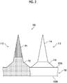
- Fig. 2 is an enlarged partial sectional view of the microneedle array 100.
- the needle portion 112 includes a needle portion 114 on the distal end side and a frustum portion 116 on the root side.
- the needle portion 112 has a so-called two-stage structure in which the inclination of the side surface of the needle portion 114 and the inclination of the side surface of the frustum portion 116 discontinuously change in appearance.
- the frustum portion 116 has two bottom surfaces and has a three-dimensional structure surrounded by a conical surface.
- the bottom surface (lower bottom surface) of the two bottom surfaces of the frustum portion 116 having a large area is connected to the sheet portion 102.
- the bottom surface (upper bottom surface) of the two bottom surfaces of the frustum portion 116 having a small area is connected to the needle portion 114. That is, of the two bottom surfaces of the frustum portion 116, the area of the bottom surface in a direction away from the sheet portion 102 is small.
- the needle portion 114 has a bottom surface with a large area and a shape having a narrowest area at the distal end apart from the bottom surface. Since the bottom surface of the needle portion 114 having a large area is connected to the upper bottom surface of the frustum portion 116, the needle portion 114 has a tapered shape in a direction away from the frustum portion 116.
- the needle portion 114 has a cone shape, and the frustum portion 116 has a truncated cone shape.
- the needle portion 114 and the frustum portion 116 are not limited to these shapes.
- the shape of the distal end of the needle portion 114 can be appropriately changed to a curved surface, a flat surface, or the like.
- the height (length) of the needle portion 112 is represented by the length of a segment from the distal end of the needle portion 112 perpendicular to the sheet portion 102.
- the height (length) of the needle portion is not particularly limited, but is preferably 50 ⁇ m or more and 3000 ⁇ m or less, more preferably 100 ⁇ m or more and 1500 ⁇ m or less, and even more preferably 100 ⁇ m or more and 1000 ⁇ m or less.
- the interval between the needle portions 112 is preferably 0.1 mm or more and 10 mm or less, more preferably 0.2 mm or more and 5 mm or less, and even more preferably 0.3 mm or more and 3 mm or less.
- the microneedle array 100 is made of a first polymer P1 containing a drug and a second polymer P2 not containing the drug.
- the needle portion 114 has a distal end portion made of the first polymer P1 and a root portion made of the second polymer P2.
- the frustum portion 116 and the sheet portion 102 are made of the second polymer P2.
- Containing a drug means containing a drug in an amount that exhibits the drug effect in a case where the body surface is punctured.
- not containing a drug means not containing a drug in an amount that exhibits the drug effect.
- the range of the amount of the drug is a range from 0, at which the drug is not contained at all, to the amount at which the drug effect is not exhibited.
- the drug is not limited as long as the drug has a function as a drug.
- the first polymer P1 is not particularly limited, and examples thereof include polysaccharides, polyvinyl pyrrolidone, polyoxyethylene polyoxypropylene glycol, polyethylene glycol, polyvinyl alcohol, and proteins (for example, gelatin).
- polysaccharides include hyaluronic acid, sodium hyaluronate, pullulan, dextran, dextrin, chondroitin sulfate, sodium chondroitin sulfate, cellulose derivatives (for example, water-soluble cellulose derivatives partially modified from cellulose, such as carboxymethyl cellulose, hydroxypropyl cellulose, and hydroxypropyl methylcellulose), hydroxyethyl starch, and gum arabic.
- the above components may be used singly or as a mixture of two or more.
- the first polymer P1 is preferably at least one selected from the group consisting of hydroxyethyl starch, dextran, chondroitin sulfate, sodium chondroitin sulfate, sodium hyaluronate, carboxymethyl cellulose, polyvinyl pyrrolidone, polyoxyethylene polyoxypropylene glycol, polyethylene glycol, and polyvinyl alcohol, and is particularly preferably sodium chondroitin sulfate.
- the second polymer P2 is not particularly limited, and examples thereof include polysaccharides, polyvinyl pyrrolidone, polyoxyethylene polyoxypropylene glycol, polyethylene glycol, polyvinyl alcohol, and proteins (for example, gelatin).
- examples of the polysaccharides include hyaluronic acid, sodium hyaluronate, pullulan, dextran, dextrin, chondroitin sulfate, sodium chondroitin sulfate, cellulose derivatives (for example, water-soluble cellulose derivatives partially modified from cellulose, such as carboxymethyl cellulose, hydroxypropyl cellulose, and hydroxypropyl methylcellulose), hydroxyethyl starch, and gum arabic.
- the above components may be used singly or as a mixture of two or more.
- the second polymer P2 is preferably at least one selected from the group consisting of hydroxyethyl starch, dextran, chondroitin sulfate, sodium chondroitin sulfate, sodium hyaluronate, carboxymethyl cellulose, polyvinyl pyrrolidone, polyoxyethylene polyoxypropylene glycol, polyethylene glycol, and polyvinyl alcohol, and is particularly preferably sodium chondroitin sulfate.
- the first polymer P1 and the second polymer P2 may be the same material or different from each other.
- Fig. 3 is an enlarged partial sectional view of the second surface 102B of the microneedle array 100.
- the second surface 102B of the sheet portion 102 is configured by a rough surface in which a plurality of peak portions 102C and valley portions 102D having different heights H (or depths) and intervals are continuous. It is preferable that the plurality of peak portions 102C and valley portions 102D are provided on the entire second surface 102B. Shape characteristics such as the height H and the intervals between the peak portions 102C and the valley portions 102D can be controlled by a manufacturing method described later.
- the microneedle array 100 is manufactured by the first polymer P1 and the second polymer P2 described above.
- the first polymer P1 and the second polymer P2 are transparent or translucent materials. Therefore, in general, the microneedle array 100 is formed to be transparent or translucent as a whole. However, since the above-described microneedle array 100 has gloss, halation is likely to occur during imaging in an appearance inspection using a light source and a camera.
- the microneedle array 100 of the embodiment comprises the sheet portion 102 roughened by the plurality of peak portions 102C and valley portions 102D.
- the sheet portion 102 of the microneedle array 100 looks cloudy, and as a result, the average transmittance of the sheet portion 102 in a wavelength range of 300 nm to 740 nm is 75% or less.
- the average transmittance of the sheet portion 102 in a wavelength range of 300 nm to 740 nm is 75% or less.
- at least the gloss of the sheet portion 102 can be suppressed.
- halation during imaging is suppressed.
- the average transmittance is more preferably 60% or less.
- the microneedle array 100 of the embodiment can suppress the gloss without using an additive such as a colorant or coloring the needle portion 112. Since the microneedle array 100 is used for medical purposes, it is preferable that addition of a colorant and coloring are not performed.
- the average transmittance is an average value of transmittance every 10 nm between 300 nm and 740 nm.
- the average transmittance of the sheet portion 102 can be measured by the following procedure.
- a sample of the microneedle array 100 to be measured is prepared.
- the sample microneedle array 100 comprises a sheet portion 102 having a diameter of 16 mm and a size of 0.3 mm or more and 0.5 mm or less.
- An apparatus was prepared by connecting a multi-purpose large-sample compartment (product name "MPC-3100", manufactured by Shimadzu Corporation) to an ultraviolet/visible spectrophotometer (product name "UV-2100” manufactured by Shimadzu Corporation), and this apparatus measures an area where the needle portions 112 of the sheet portion 102 are not formed. With this apparatus, the transmittance of each wavelength light (every 10 nm) between 300 nm and 740 nm is measured. The average transmittance of the sheet portion 102 in a wavelength range of 300 nm to 740 nm can be obtained.
- an inspection apparatus 200 comprises a support base 210 that supports the microneedle array 100, an illumination unit 220 that illuminates the microneedle array 100 with illumination light, and an imaging unit 240 that images the microneedle array 100, and an image processing device 250 that inspects the microneedle array 100 based on the image imaged by the imaging unit 240.
- the support base 210 supports the microneedle array 100.
- the support base 210 comprises a flat mounting surface for supporting the microneedle array 100.
- the microneedle array 100 is placed with the roughened second surface 102B side opposing the mounting surface.
- the support base 210 may comprise a drive device (not illustrated).
- the drive device can move the support base 210 in an X-axis direction, a Y-axis direction, and a Z-axis direction, and can rotate around the Z-axis direction.
- the illumination unit 220 comprises a light source and a lens (not illustrated).
- the light source includes, for example, a white light emitting diode.
- the illumination unit 220 illuminates the microneedle array 100 with light in a direction inclined at a predetermined angle with respect to the normal line NL of the sheet portion 102 from the needle portion 112 side.
- the optical axis of the illumination unit 220 is inclined at a predetermined angle with respect to the normal line NL.
- the illumination unit 220 may comprise a drive mechanism (not illustrated). The drive mechanism can change the angle at which the microneedle array 100 is illuminated.
- the imaging unit 240 comprises a camera 242 and a lens 244.
- the camera 242 is a so-called digital camera, receives light with an imaging element, converts the received light into a digital signal, and outputs the digital signal.
- the imaging unit 240 images the microneedle array 100 in a direction inclined at a predetermined angle with respect to the normal line NL of the sheet portion 102 from the needle portion 112 side.
- the optical axis of the imaging unit 240 is inclined at a predetermined angle with respect to the normal line NL.
- the imaging unit 240 may comprise a drive mechanism (not illustrated). The drive mechanism can change the angle at which the microneedle array 100 is imaged.
- the illumination unit 220 and the imaging unit 240 are disposed substantially symmetrically about the normal line NL.
- the image processing device 250 analyzes the image data of the microneedle array 100 imaged by the imaging unit 240, and inspects the individual needle portions 112 and the sheet portion 102 provided in the microneedle array 100.
- the image processing device 250 inspects the shape quality of the needle portion 112 and the sheet portion 102, the presence or absence of foreign matter, and the like.
- the image processing device 250 is configured by a computer.
- the computer comprises an arithmetic device and executes a predetermined inspection program.
- the inspection program causes the computer to function as the image processing device 250.
- a display, an input device, a recording device, and the like are connected to the computer.
- the image processing device 250 can execute overall control of the inspection apparatus 200 as well as the inspection program.
- the inspection is performed by illuminating the microneedle array 100 placed on the support base 210 with light from the needle portion 112 side, imaging the reflected light by the imaging unit 240 from the needle portion 112 side, and analyzing the obtained image data by the image processing device 250.
- the second surface 102B of the sheet portion 102 of the microneedle array 100 is roughened, halation during imaging of the microneedle array 100 is suppressed. The visibility of the appearance inspection of the microneedle array 100 can be improved.
- a mold 300 in which a plurality of recessed portions 310 are formed is prepared.
- the recessed portion 310 has an inverted shape of the needle portion 112 of the microneedle array 100.
- the mold 300 comprises a weir 320 which has a certain height with respect to the opening surface of the recessed portion 310 and surrounds the plurality of recessed portions 310.
- the mold 300 can be made of, for example, a silicone resin.
- a flat surface 330 is provided between the recessed portion 310 and the weir 320.
- the mold 300 can be produced using a plate precursor (not illustrated) that is a duplicate of the microneedle array 100.
- the plate precursor is produced by machining a metal substrate using a cutting tool such as a diamond tool.
- a cutting tool such as a diamond tool.
- the metal substrate stainless steel, an aluminum alloy, Ni, or the like can be used.
- the mold 300 in which the plurality of recessed portions 310 are formed is produced by adding a silicone resin before being cured dropwise onto a plate precursor, thereafter curing the silicone resin, and peeling the cured silicone resin from the plate precursor.
- the plurality of recessed portions 310 are filled with a first liquid PL1 containing the first polymer P1 and the drug, and then the first liquid PL1 is dried, whereby at least the distal end portion of the needle portion 112 of the microneedle array 100 (not illustrated) is formed of the first polymer P1 containing the drug.
- a needle portion forming step at least the distal end portion of the needle portion 112 made of the first polymer P1 is formed.
- the entire needle portion 114 (the root portion and the distal end portion) of the needle portion 112 may be formed, or the entire needle portion 112 (the needle portion 114 and the frustum portion 116) may also be formed.
- the size of the needle portion 112 formed in the needle portion forming step is determined by the supply amount of the first liquid.
- the first liquid PL1 can be caused to fill only the recessed portions 310 by bringing the distal end portion of a slit nozzle into contact with the mold 300.
- the first liquid PL1 can be caused to fill the recessed portions 310 by supplying the first liquid onto the mold 300 with a nozzle, a dispenser, or the like and then bringing a blade into contact with the mold 300.
- the first liquid PL1 can be filled by being discharged only to the recessed portions 310 from the nozzle.
- FIG. 7 in order to form the sheet portion 102 (not illustrated) having the first surface 102A on which the needle portions 112 are arranged and the second surface 102B opposing the first surface 102A, the plurality of recessed portions 310 in which at least the distal end portion of the needle portion 112 (first polymer P1) is formed is filled with a second liquid PL2 containing the second polymer P2.
- the second polymer P2 does not contain a drug.
- the second liquid PL2 is filled beyond the recessed portions 310 and filled until the height thereof is about the same as the weir 320.
- the second liquid PL2 is filled by being supplied by a spencer.
- the second liquid PL2 can be filled by applying spin coating, spray coating, or the like.
- the second liquid PL2 filling the mold 300 is dried.
- the second liquid PL2 becomes the second polymer P2, and the microneedle array 100 having the sheet portion 102 and the needle portions 112 in the mold 300 is manufactured.
- the second liquid PL2 contains an aqueous polysaccharide solution
- the drying rate moisture evaporation rate
- the crystallinity of the polysaccharide by controlling the drying rate (moisture evaporation rate) and controlling the crystallinity of the polysaccharide, the peak portions 102C and the valley portions 102D are formed on the second surface 102B of the sheet portion 102, whereby the second surface 102B is roughened.
- the sheet portion 102 appears cloudy.
- the drying rate is preferably low, and under the control of the drying rate, a rough surface having the peak portions 102C and the valley portions 102D can be formed on the second surface 102B, and the average transmittance of the sheet portion 102 in a wavelength range of 300 nm to 740 nm can be 75% or less.
- the drying rate is preferably 50 g/(hr ⁇ m 2 ) or less until the concentration of solid contents of the second liquid PL2 reaches 80 wt% in terms of weight percentage. Since the concentration of solid content varies in a thickness direction and an in-plane direction and there is a concentration distribution, the average concentration of solid contents of the entire second liquid PL2 can be used. For example, a change in the concentration of solid contents is preferably calculated by measuring a weight change in the drying step.
- the drying rate is the mass of water that evaporates per unit time and unit area.
- the average transmittance of the sheet portion 102 in a wavelength range of 300 nm to 740 nm can be 75% or less, and furthermore 60% or less by performing the drying under conditions of a low drying rate.
- the control of the drying rate of the second liquid PL2 is performed by controlling the temperature and humidity of a drying environment and installing a cap 400 with a plurality of openings 410 formed therein immediately above the mold 300.
- the mold 300 and the cap 400 are placed on a support base 420.
- the cap 400 is disposed at a position covering at least the second liquid PL2 filling the mold 300.
- the openings 410 are positioned at locations opposing the second liquid PL2.
- the cap 400 covers the entire mold 300.
- the second liquid PL2 is dried at a low temperature and a high humidity in order to reduce the drying rate.
- the positions where the openings 410 are provided are not particularly limited.
- the second liquid PL2 becomes the second polymer P2, and the microneedle array 100 having the sheet portion 102 and the needle portions 112 is manufactured in the mold 300.
- the peak portions 102C and the valley portions 102D are formed on the second surface 102B of the sheet portion 102, whereby the second surface 102B is roughened.
- the cap 400 covering the second liquid PL2 suppresses wind hitting the surface of the second liquid PL2, and further increases the relative humidity inside the cap 400. As a result, it is possible to reduce the drying rate.
- the control of the drying rate has been described as a method of roughening the second surface 102B of the sheet portion 102 of the microneedle array 100.
- a processing step of performing a chemical treatment such as dry etching or a physical treatment such as sandpaper polishing on the second surface 102B of the sheet portion 102 may be included after the sheet portion forming step.
- the control of the drying rate is preferable because damage to the microneedle array 100 is small and no additional step is required compared to a method of chemically or physically roughening the second surface 102B.
- a mold having an inverted mold of the shape of the microneedle array is prepared.
- the mold is made of silicone rubber ("SIL-5930", manufactured by Nusil.) and has a diameter of 20 mm.
- the mold comprises a surrounding weir with a width of 2 mm and a height of 0.5 mm.
- the mold was filled with a second liquid to be a sheet portion.
- a second liquid to be a sheet portion 250 mg to 300 mg of sodium chondroitin sulfate having a concentration of solid contents of 40 wt% was added dropwise into the mold to fill the mold.
- the second liquid was dried at a drying rate of 75 g/(hr ⁇ m 2 ) until the concentration of solid contents of the second liquid reached 80 wt%. Thereafter, a microneedle array was produced by peeling the microneedle array from the mold.
- a microneedle array was produced under the same conditions as in Test 1 except that the drying conditions for the second liquid were changed.
- the second liquid was dried at a drying rate of 56 g/(hr ⁇ m 2 ) until the concentration of solid contents of the second liquid reached 80 wt%.
- a microneedle array was produced under the same conditions as in Test 1 except that the drying conditions for the second liquid were changed.
- the second liquid was dried at a drying rate of 50 g/(hr ⁇ m 2 ) until the concentration of solid contents of the second liquid reached 80 wt%.
- a microneedle array was produced under the same conditions as in Test 1 except that the drying conditions for the second liquid were changed.
- the second liquid was covered with a cap with openings formed therein, and the second liquid was dried at a drying rate of 20 g/(hr ⁇ m 2 ) until the concentration of solid contents of the second liquid reached 80 wt%.
- the drying rate of each test based on a graph with weight decrease (amount of volatilized moisture) (mg) on the vertical axis and drying time (hr) on the horizontal axis, the drying rate was calculated from the gradient of a range in which the weight decrease during the drying step became a linear region.
- the weight decrease was linear in a range in which the concentration of solid contents of the second liquid was 80 wt% or less.
- the average transmittance of the sheet portion of the microneedle array of Test 1 was 80.0%.
- the average transmittance of the sheet portion of the microneedle array in Test 2 was 75.6%.
- the average transmittance of the sheet portion of the microneedle array in Test 3 was 66.3%.
- the average transmittance of the sheet portion of the microneedle array in Test 4 was 55.0%. In Test 3 and Test 4, the average transmittance of the sheet portion could be 75% or less.
- Fig. 13 is an image of the microneedle array of Test 1
- Fig. 14 is an image of the microneedle array of Test 3.
- the needle portion and the sheet portion had gloss.
- the needle portion and the sheet portion became cloudy and had almost no gloss.
- the external shape of the needle portion was clearly confirmed.
Landscapes
- Health & Medical Sciences (AREA)
- Engineering & Computer Science (AREA)
- Dermatology (AREA)
- Medical Informatics (AREA)
- Anesthesiology (AREA)
- Biomedical Technology (AREA)
- Heart & Thoracic Surgery (AREA)
- Hematology (AREA)
- Life Sciences & Earth Sciences (AREA)
- Animal Behavior & Ethology (AREA)
- General Health & Medical Sciences (AREA)
- Public Health (AREA)
- Veterinary Medicine (AREA)
- Media Introduction/Drainage Providing Device (AREA)
Abstract
Description
- The present invention relates to a microneedle array and a manufacturing method of the same, and more particularly to a technique regarding an improvement in the visibility of an appearance inspection.
- As a method of administering a drug into the human body, a method using a microneedle array in which needle portions (also referred to as "microneedles") having a high aspect ratio are formed has been widely studied. A microneedle array administers a drug into the human body by inserting needle portions containing the drug into the skin.
- Since the microneedle array is used for medical purposes, it is necessary to inspect the shape of the needle portion, the presence or absence of foreign matter, and the like. For example,
JP2016-166769A - However, in a case where a transparent or translucent microneedle array has gloss, halation is likely to occur during imaging in an appearance inspection of needle shapes and foreign matter in which a light source and a camera is used, and visibility is lowered, so that there is concern that it may become difficult to perform the inspection.
- The present invention has been made taking the above circumstances into consideration, and an object thereof is to provide a microneedle array capable of improving the visibility of an appearance inspection of the microneedle array, and a manufacturing method of the same.
- A microneedle array according to a first aspect comprises: a sheet portion having a first surface and a second surface which oppose each other; and a plurality of needle portions arranged on the first surface of the sheet portion, wherein the second surface of the sheet portion is configured by a rough surface having peak portions and valley portions, and an average transmittance of the sheet portion in a wavelength range of 300 nm to 740 nm is 75% or less.
- According to the first aspect, the visibility of an appearance inspection of the microneedle array can be improved.
- In the microneedle array according to a second aspect, the average transmittance is 60% or less. According to the second aspect, in the appearance inspection of the microneedle array, the visibility can be further improved.
- In the microneedle array according to a third aspect, the sheet portion contains sodium chondroitin sulfate. According to the third aspect, a material preferable for the sheet portion is defined, and the peak portions and the valley portions can be formed on the second surface of the sheet portion.
- In the microneedle array according to a fourth aspect, the needle portion contains a drug. According to the fourth aspect, the drug can be administered into the skin.
- A manufacturing method of a microneedle array according to a fifth aspect comprises: a needle portion forming step of, in order to form at least a distal end portion of a needle portion, filling a plurality of recessed portions formed in a mold with a first liquid and drying the first liquid; and a sheet portion forming step of, in order to form a sheet portion having a first surface on which the needle portion is disposed and a second surface opposing the first surface, filling the plurality of recessed portions, in which at least the distal end portion of the needle portion is formed, with a second liquid, and drying the second liquid to form a rough surface having peak portions and valley portions on the second surface and cause an average transmittance of the sheet portion in a wavelength range of 300 nm to 740 nm to be 75% or less.
- According to the fifth aspect, the microneedle array capable of improving the visibility of an appearance inspection can be manufactured.
- In the manufacturing method of a microneedle array according to a sixth aspect, in the sheet portion forming step, drying is performed at a rate of 50 g/(hr·m2) or less until a concentration of solid contents of the second liquid reaches 80 wt%. According to the sixth aspect, by setting the drying condition of the second liquid within the above-described range, the peak portions and the valley portions can be formed on the second surface of the sheet portion.
- In the manufacturing method of a microneedle array according to a seventh aspect, the second liquid contains sodium chondroitin sulfate. According to the seventh aspect, as in the third aspect, a material preferable for the sheet portion is defined, and the peak portions and the valley portions can be formed on the second surface of the sheet portion.
- In the manufacturing method of a microneedle array according to an eighth aspect, the first liquid contains a drug. According to the eighth aspect, the drug can be contained in the needle portion.
- In the manufacturing method of a microneedle array according to a ninth aspect, the sheet portion forming step includes covering the second liquid with a cap in which an opening is formed. According to the ninth aspect, the drying rate can be reduced.
- A manufacturing method of a microneedle array according to a tenth aspect comprises: a needle portion forming step of, in order to form at least a distal end portion of a needle portion, filling a plurality of recessed portions formed in a mold with a first liquid and drying the first liquid; a sheet portion forming step of, in order to form a sheet portion having a first surface on which the needle portion is disposed and a second surface opposing the first surface, filling the plurality of recessed portions, in which at least the distal end portion of the needle portion is formed, with a second liquid, and drying the second liquid; and a processing step of chemically or physically treating the second surface of the sheet portion to form a rough surface having peak portions and valley portions on the second surface and cause an average transmittance of the sheet portion in a wavelength range of 300 nm to 740 nm to be 75% or less.
- According to the tenth aspect, as in the fifth aspect, the microneedle array capable of improving the visibility of an appearance inspection can be manufactured.
- According to the present invention, the visibility of an appearance inspection of the microneedle array can be improved.
-
-
Fig. 1 is a perspective view illustrating a schematic configuration of a microneedle array. -
Fig. 2 is an enlarged partial sectional view of the microneedle array. -
Fig. 3 is an enlarged partial sectional view of a second surface of the microneedle array. -
Fig. 4 is a schematic configuration diagram of an inspection apparatus. -
Fig. 5 is a diagram for describing a step of manufacturing the microneedle array. -
Fig. 6 is a diagram for describing a step of manufacturing the microneedle array. -
Fig. 7 is a diagram for describing a step of manufacturing the microneedle array. -
Fig. 8 is a diagram for describing a step of manufacturing the microneedle array. -
Fig. 9 is a diagram for describing a step of manufacturing the microneedle array. -
Fig. 10 is a diagram for describing a step of manufacturing the microneedle array. -
Fig. 11 is a graph for calculating a drying rate. -
Fig. 12 is a graph plotting transmittance. -
Fig. 13 is an enlarged image of a part of a microneedle array inTest 1. -
Fig. 14 is an enlarged image of a part of a microneedle array inTest 3. - Hereinafter, preferred embodiments of the present invention will be described with reference to the accompanying drawings. The present invention is described by the following preferred embodiments. Modifications can be made by various methods without departing from the scope of the present invention, and other embodiments than the embodiments can also be used. Therefore, all modifications within the scope of the present invention are included in the appended claims.
- Here, in the figures, like elements having similar functions are denoted by like reference numerals. In addition, in this specification, in a case where a numerical value range is expressed using "to", the numerical value range includes the numerical values of the upper limit and the lower limit indicated by "to".
- An example of a microneedle array (percutaneous absorption sheet) will be described.
-
Fig. 1 is a perspective view illustrating an example of amicroneedle array 100. Themicroneedle array 100 of the embodiment corresponds to a patch for one administration. Themicroneedle array 100 comprises asheet portion 102 having afirst surface 102A and asecond surface 102B which oppose each other, andneedle portions 112 arranged on thefirst surface 102A of thesheet portion 102. - The
sheet portion 102 has a thin flat shape as a whole with respect to the two opposing first andsecond surfaces sheet portion 102 illustrated inFig. 1 is circular in a plan view, thesheet portion 102 may be rectangular, polygonal, elliptical, or the like. Here, the plan view means a state in which thefirst surface 102A is observed in a direction orthogonal to thefirst surface 102A. - A plurality of the
needle portions 112 are arranged on thefirst surface 102A of thesheet portion 102 in a predetermined pattern. The plurality of arrangedneedle portions 112 constitute anarray pattern 110. For example, thearray pattern 110 can be configured by arranging the plurality ofneedle portions 112 in a concentric shape, and can also be configured by arranging the plurality ofneedle portions 112 in a lattice shape. Thearray pattern 110 is not particularly limited and can be changed as appropriate. - The
array pattern 110 is constituted by, for example, 4 to 2500needle portions 112. However, the number ofneedle portions 112 is not limited to this number. - The
needle portion 112 is configured in a shape having a narrow distal end as compared with the root in contact with thesheet portion 102. Examples of the shape of theneedle portion 112 include a cone shape, a polygonal pyramid shape (such as a quadrangular pyramid shape), or a spindle shape. The overall shape of theneedle portion 112 may be a cone shape or a polygonal pyramid shape (such as a quadrangular pyramid shape), or may be a structure in which the inclination (angle) of the side surface of the needle portion is continuously changed. Alternatively, a multilayer structure of two or more layers in which the inclination (angle) of the side surface of the needle portion changes discontinuously may also be adopted. -
Fig. 2 is an enlarged partial sectional view of themicroneedle array 100. Theneedle portion 112 includes aneedle portion 114 on the distal end side and afrustum portion 116 on the root side. Theneedle portion 112 has a so-called two-stage structure in which the inclination of the side surface of theneedle portion 114 and the inclination of the side surface of thefrustum portion 116 discontinuously change in appearance. - The
frustum portion 116 has two bottom surfaces and has a three-dimensional structure surrounded by a conical surface. The bottom surface (lower bottom surface) of the two bottom surfaces of thefrustum portion 116 having a large area is connected to thesheet portion 102. The bottom surface (upper bottom surface) of the two bottom surfaces of thefrustum portion 116 having a small area is connected to theneedle portion 114. That is, of the two bottom surfaces of thefrustum portion 116, the area of the bottom surface in a direction away from thesheet portion 102 is small. - The
needle portion 114 has a bottom surface with a large area and a shape having a narrowest area at the distal end apart from the bottom surface. Since the bottom surface of theneedle portion 114 having a large area is connected to the upper bottom surface of thefrustum portion 116, theneedle portion 114 has a tapered shape in a direction away from thefrustum portion 116. - In the form of
Figs. 1 and2 , theneedle portion 114 has a cone shape, and thefrustum portion 116 has a truncated cone shape. However, theneedle portion 114 and thefrustum portion 116 are not limited to these shapes. Depending on the degree of insertion of theneedle portion 114 into the skin, the shape of the distal end of theneedle portion 114 can be appropriately changed to a curved surface, a flat surface, or the like. - The height (length) of the
needle portion 112 is represented by the length of a segment from the distal end of theneedle portion 112 perpendicular to thesheet portion 102. The height (length) of the needle portion is not particularly limited, but is preferably 50 µm or more and 3000 ≈µm or less, more preferably 100 µm or more and 1500 µm or less, and even more preferably 100 µm or more and 1000 µm or less. - The interval between the
needle portions 112 is preferably 0.1 mm or more and 10 mm or less, more preferably 0.2 mm or more and 5 mm or less, and even more preferably 0.3 mm or more and 3 mm or less. - The
microneedle array 100 is made of a first polymer P1 containing a drug and a second polymer P2 not containing the drug. Theneedle portion 114 has a distal end portion made of the first polymer P1 and a root portion made of the second polymer P2. Thefrustum portion 116 and thesheet portion 102 are made of the second polymer P2. - Containing a drug means containing a drug in an amount that exhibits the drug effect in a case where the body surface is punctured. In addition, not containing a drug means not containing a drug in an amount that exhibits the drug effect. In a case of not containing a drug, the range of the amount of the drug is a range from 0, at which the drug is not contained at all, to the amount at which the drug effect is not exhibited.
- The drug is not limited as long as the drug has a function as a drug. In particular, it is preferable to select from pharmaceutical compounds belonging to peptides, proteins, nucleic acids, polysaccharides, vaccines, and water-soluble low-molecular compounds.
- The first polymer P1 is not particularly limited, and examples thereof include polysaccharides, polyvinyl pyrrolidone, polyoxyethylene polyoxypropylene glycol, polyethylene glycol, polyvinyl alcohol, and proteins (for example, gelatin). Examples of the polysaccharides include hyaluronic acid, sodium hyaluronate, pullulan, dextran, dextrin, chondroitin sulfate, sodium chondroitin sulfate, cellulose derivatives (for example, water-soluble cellulose derivatives partially modified from cellulose, such as carboxymethyl cellulose, hydroxypropyl cellulose, and hydroxypropyl methylcellulose), hydroxyethyl starch, and gum arabic. The above components may be used singly or as a mixture of two or more.
- Among the above components, the first polymer P1 is preferably at least one selected from the group consisting of hydroxyethyl starch, dextran, chondroitin sulfate, sodium chondroitin sulfate, sodium hyaluronate, carboxymethyl cellulose, polyvinyl pyrrolidone, polyoxyethylene polyoxypropylene glycol, polyethylene glycol, and polyvinyl alcohol, and is particularly preferably sodium chondroitin sulfate.
- The second polymer P2 is not particularly limited, and examples thereof include polysaccharides, polyvinyl pyrrolidone, polyoxyethylene polyoxypropylene glycol, polyethylene glycol, polyvinyl alcohol, and proteins (for example, gelatin). Examples of the polysaccharides include hyaluronic acid, sodium hyaluronate, pullulan, dextran, dextrin, chondroitin sulfate, sodium chondroitin sulfate, cellulose derivatives (for example, water-soluble cellulose derivatives partially modified from cellulose, such as carboxymethyl cellulose, hydroxypropyl cellulose, and hydroxypropyl methylcellulose), hydroxyethyl starch, and gum arabic. The above components may be used singly or as a mixture of two or more.
- Among the above components, the second polymer P2 is preferably at least one selected from the group consisting of hydroxyethyl starch, dextran, chondroitin sulfate, sodium chondroitin sulfate, sodium hyaluronate, carboxymethyl cellulose, polyvinyl pyrrolidone, polyoxyethylene polyoxypropylene glycol, polyethylene glycol, and polyvinyl alcohol, and is particularly preferably sodium chondroitin sulfate.
- The first polymer P1 and the second polymer P2 may be the same material or different from each other.
-
Fig. 3 is an enlarged partial sectional view of thesecond surface 102B of themicroneedle array 100. Thesecond surface 102B of thesheet portion 102 is configured by a rough surface in which a plurality ofpeak portions 102C andvalley portions 102D having different heights H (or depths) and intervals are continuous. It is preferable that the plurality ofpeak portions 102C andvalley portions 102D are provided on the entiresecond surface 102B. Shape characteristics such as the height H and the intervals between thepeak portions 102C and thevalley portions 102D can be controlled by a manufacturing method described later. - The
microneedle array 100 is manufactured by the first polymer P1 and the second polymer P2 described above. The first polymer P1 and the second polymer P2 are transparent or translucent materials. Therefore, in general, themicroneedle array 100 is formed to be transparent or translucent as a whole. However, since the above-describedmicroneedle array 100 has gloss, halation is likely to occur during imaging in an appearance inspection using a light source and a camera. - The
microneedle array 100 of the embodiment comprises thesheet portion 102 roughened by the plurality ofpeak portions 102C andvalley portions 102D. Thesheet portion 102 of themicroneedle array 100 looks cloudy, and as a result, the average transmittance of thesheet portion 102 in a wavelength range of 300 nm to 740 nm is 75% or less. In themicroneedle array 100, at least the gloss of thesheet portion 102 can be suppressed. In the appearance inspection of themicroneedle array 100, halation during imaging is suppressed. In addition, since halation is suppressed as the average transmittance decreases, the average transmittance is more preferably 60% or less. - The
microneedle array 100 of the embodiment can suppress the gloss without using an additive such as a colorant or coloring theneedle portion 112. Since themicroneedle array 100 is used for medical purposes, it is preferable that addition of a colorant and coloring are not performed. - Here, the average transmittance is an average value of transmittance every 10 nm between 300 nm and 740 nm. The average transmittance of the
sheet portion 102 can be measured by the following procedure. - A sample of the
microneedle array 100 to be measured is prepared. Thesample microneedle array 100 comprises asheet portion 102 having a diameter of 16 mm and a size of 0.3 mm or more and 0.5 mm or less. An apparatus was prepared by connecting a multi-purpose large-sample compartment (product name "MPC-3100", manufactured by Shimadzu Corporation) to an ultraviolet/visible spectrophotometer (product name "UV-2100" manufactured by Shimadzu Corporation), and this apparatus measures an area where theneedle portions 112 of thesheet portion 102 are not formed. With this apparatus, the transmittance of each wavelength light (every 10 nm) between 300 nm and 740 nm is measured. The average transmittance of thesheet portion 102 in a wavelength range of 300 nm to 740 nm can be obtained. - A microneedle array inspection method will be described with reference to
Fig. 4 . As illustrated inFig. 4 , aninspection apparatus 200 comprises asupport base 210 that supports themicroneedle array 100, anillumination unit 220 that illuminates themicroneedle array 100 with illumination light, and animaging unit 240 that images themicroneedle array 100, and animage processing device 250 that inspects themicroneedle array 100 based on the image imaged by theimaging unit 240. - The
support base 210 supports themicroneedle array 100. Thesupport base 210 comprises a flat mounting surface for supporting themicroneedle array 100. Themicroneedle array 100 is placed with the roughenedsecond surface 102B side opposing the mounting surface. - The
support base 210 may comprise a drive device (not illustrated). The drive device can move thesupport base 210 in an X-axis direction, a Y-axis direction, and a Z-axis direction, and can rotate around the Z-axis direction. - The
illumination unit 220 comprises a light source and a lens (not illustrated). The light source includes, for example, a white light emitting diode. Theillumination unit 220 illuminates themicroneedle array 100 with light in a direction inclined at a predetermined angle with respect to the normal line NL of thesheet portion 102 from theneedle portion 112 side. The optical axis of theillumination unit 220 is inclined at a predetermined angle with respect to the normal line NL. Theillumination unit 220 may comprise a drive mechanism (not illustrated). The drive mechanism can change the angle at which themicroneedle array 100 is illuminated. - The
imaging unit 240 comprises acamera 242 and alens 244. Thecamera 242 is a so-called digital camera, receives light with an imaging element, converts the received light into a digital signal, and outputs the digital signal. Theimaging unit 240 images themicroneedle array 100 in a direction inclined at a predetermined angle with respect to the normal line NL of thesheet portion 102 from theneedle portion 112 side. The optical axis of theimaging unit 240 is inclined at a predetermined angle with respect to the normal line NL. Theimaging unit 240 may comprise a drive mechanism (not illustrated). The drive mechanism can change the angle at which themicroneedle array 100 is imaged. Theillumination unit 220 and theimaging unit 240 are disposed substantially symmetrically about the normal line NL. - The
image processing device 250 analyzes the image data of themicroneedle array 100 imaged by theimaging unit 240, and inspects theindividual needle portions 112 and thesheet portion 102 provided in themicroneedle array 100. Theimage processing device 250 inspects the shape quality of theneedle portion 112 and thesheet portion 102, the presence or absence of foreign matter, and the like. - For example, the
image processing device 250 is configured by a computer. The computer comprises an arithmetic device and executes a predetermined inspection program. The inspection program causes the computer to function as theimage processing device 250. A display, an input device, a recording device, and the like are connected to the computer. Theimage processing device 250 can execute overall control of theinspection apparatus 200 as well as the inspection program. - The inspection is performed by illuminating the
microneedle array 100 placed on thesupport base 210 with light from theneedle portion 112 side, imaging the reflected light by theimaging unit 240 from theneedle portion 112 side, and analyzing the obtained image data by theimage processing device 250. - Since the
second surface 102B of thesheet portion 102 of themicroneedle array 100 is roughened, halation during imaging of themicroneedle array 100 is suppressed. The visibility of the appearance inspection of themicroneedle array 100 can be improved. - Next, a manufacturing method of the microneedle array will be described with reference to
Figs. 5 to 10 . As shown inFig. 5 , in order to produce themicroneedle array 100, amold 300 in which a plurality of recessedportions 310 are formed is prepared. The recessedportion 310 has an inverted shape of theneedle portion 112 of themicroneedle array 100. Themold 300 comprises aweir 320 which has a certain height with respect to the opening surface of the recessedportion 310 and surrounds the plurality of recessedportions 310. Themold 300 can be made of, for example, a silicone resin. Aflat surface 330 is provided between the recessedportion 310 and theweir 320. - The
mold 300 can be produced using a plate precursor (not illustrated) that is a duplicate of themicroneedle array 100. The plate precursor is produced by machining a metal substrate using a cutting tool such as a diamond tool. As the metal substrate, stainless steel, an aluminum alloy, Ni, or the like can be used. - The
mold 300 in which the plurality of recessedportions 310 are formed is produced by adding a silicone resin before being cured dropwise onto a plate precursor, thereafter curing the silicone resin, and peeling the cured silicone resin from the plate precursor. - In the manufacturing of the microneedle array, as illustrated in
Fig. 6 , the plurality of recessedportions 310 are filled with a first liquid PL1 containing the first polymer P1 and the drug, and then the first liquid PL1 is dried, whereby at least the distal end portion of theneedle portion 112 of the microneedle array 100 (not illustrated) is formed of the first polymer P1 containing the drug. In a needle portion forming step, at least the distal end portion of theneedle portion 112 made of the first polymer P1 is formed. In the needle portion forming step, the entire needle portion 114 (the root portion and the distal end portion) of theneedle portion 112 may be formed, or the entire needle portion 112 (theneedle portion 114 and the frustum portion 116) may also be formed. The size of theneedle portion 112 formed in the needle portion forming step is determined by the supply amount of the first liquid. - Although not particularly limited, the first liquid PL1 can be caused to fill only the recessed
portions 310 by bringing the distal end portion of a slit nozzle into contact with themold 300. The first liquid PL1 can be caused to fill the recessedportions 310 by supplying the first liquid onto themold 300 with a nozzle, a dispenser, or the like and then bringing a blade into contact with themold 300. The first liquid PL1 can be filled by being discharged only to the recessedportions 310 from the nozzle. - A sheet portion forming step shown in
Figs. 7 and8 will be described. As illustrated inFig. 7 , in order to form the sheet portion 102 (not illustrated) having thefirst surface 102A on which theneedle portions 112 are arranged and thesecond surface 102B opposing thefirst surface 102A, the plurality of recessedportions 310 in which at least the distal end portion of the needle portion 112 (first polymer P1) is formed is filled with a second liquid PL2 containing the second polymer P2. The second polymer P2 does not contain a drug. The second liquid PL2 is filled beyond the recessedportions 310 and filled until the height thereof is about the same as theweir 320. - Although not particularly limited, the second liquid PL2 is filled by being supplied by a spencer. The second liquid PL2 can be filled by applying spin coating, spray coating, or the like.
- As illustrated in
Fig. 8 , the second liquid PL2 filling themold 300 is dried. In a case where the drying is finished, the second liquid PL2 becomes the second polymer P2, and themicroneedle array 100 having thesheet portion 102 and theneedle portions 112 in themold 300 is manufactured. In particular, in a case where the second liquid PL2 contains an aqueous polysaccharide solution, by controlling the drying rate (moisture evaporation rate) and controlling the crystallinity of the polysaccharide, thepeak portions 102C and thevalley portions 102D are formed on thesecond surface 102B of thesheet portion 102, whereby thesecond surface 102B is roughened. Thesheet portion 102 appears cloudy. - The drying rate is preferably low, and under the control of the drying rate, a rough surface having the
peak portions 102C and thevalley portions 102D can be formed on thesecond surface 102B, and the average transmittance of thesheet portion 102 in a wavelength range of 300 nm to 740 nm can be 75% or less. The drying rate is preferably 50 g/(hr·m2) or less until the concentration of solid contents of the second liquid PL2 reaches 80 wt% in terms of weight percentage. Since the concentration of solid content varies in a thickness direction and an in-plane direction and there is a concentration distribution, the average concentration of solid contents of the entire second liquid PL2 can be used. For example, a change in the concentration of solid contents is preferably calculated by measuring a weight change in the drying step. The drying rate is the mass of water that evaporates per unit time and unit area. - In particular, in a case where the aqueous polysaccharide solution is sodium chondroitin sulfate, the average transmittance of the
sheet portion 102 in a wavelength range of 300 nm to 740 nm can be 75% or less, and furthermore 60% or less by performing the drying under conditions of a low drying rate. - Next, another sheet portion forming step will be described with reference to
Figs. 9 and10 . For example, as illustrated inFig. 9 , the control of the drying rate of the second liquid PL2 is performed by controlling the temperature and humidity of a drying environment and installing acap 400 with a plurality ofopenings 410 formed therein immediately above themold 300. - The
mold 300 and thecap 400 are placed on asupport base 420. Thecap 400 is disposed at a position covering at least the second liquid PL2 filling themold 300. Theopenings 410 are positioned at locations opposing the second liquid PL2. InFig. 9 , thecap 400 covers theentire mold 300. The second liquid PL2 is dried at a low temperature and a high humidity in order to reduce the drying rate. The positions where theopenings 410 are provided are not particularly limited. - As illustrated in
Fig. 10 , in a case where drying is finished, the second liquid PL2 becomes the second polymer P2, and themicroneedle array 100 having thesheet portion 102 and theneedle portions 112 is manufactured in themold 300. Thepeak portions 102C and thevalley portions 102D are formed on thesecond surface 102B of thesheet portion 102, whereby thesecond surface 102B is roughened. Thecap 400 covering the second liquid PL2 suppresses wind hitting the surface of the second liquid PL2, and further increases the relative humidity inside thecap 400. As a result, it is possible to reduce the drying rate. - The control of the drying rate has been described as a method of roughening the
second surface 102B of thesheet portion 102 of themicroneedle array 100. As a roughening method other than the control of the drying rate, a processing step of performing a chemical treatment such as dry etching or a physical treatment such as sandpaper polishing on thesecond surface 102B of thesheet portion 102 may be included after the sheet portion forming step. - The control of the drying rate is preferable because damage to the
microneedle array 100 is small and no additional step is required compared to a method of chemically or physically roughening thesecond surface 102B. - Hereinafter, the present invention will be described in more detail with reference to examples of the present invention. In addition, the material, use amount, ratio, processing content, processing procedure, and the like described in the following examples can be modified as appropriate without departing from the gist of the present invention. Therefore, the scope of the present invention should not be construed as being limited by the specific examples shown below.
- A mold having an inverted mold of the shape of the microneedle array is prepared. The mold is made of silicone rubber ("SIL-5930", manufactured by Nusil.) and has a diameter of 20 mm. The mold comprises a surrounding weir with a width of 2 mm and a height of 0.5 mm.
- The mold was filled with a second liquid to be a sheet portion. As an aqueous polysaccharide solution to be the second liquid, 250 mg to 300 mg of sodium chondroitin sulfate having a concentration of solid contents of 40 wt% was added dropwise into the mold to fill the mold.
- In an environment of 23°C/45% RH (relative humidity), the second liquid was dried at a drying rate of 75 g/(hr·m2) until the concentration of solid contents of the second liquid reached 80 wt%. Thereafter, a microneedle array was produced by peeling the microneedle array from the mold.
- A microneedle array was produced under the same conditions as in
Test 1 except that the drying conditions for the second liquid were changed. In an environment of 24°C/40% RH (relative humidity), the second liquid was dried at a drying rate of 56 g/(hr·m2) until the concentration of solid contents of the second liquid reached 80 wt%. - A microneedle array was produced under the same conditions as in
Test 1 except that the drying conditions for the second liquid were changed. In an environment of 23°C/45% RH (relative humidity), the second liquid was dried at a drying rate of 50 g/(hr·m2) until the concentration of solid contents of the second liquid reached 80 wt%. - A microneedle array was produced under the same conditions as in
Test 1 except that the drying conditions for the second liquid were changed. In an environment of 23°C/45% RH (relative humidity), the second liquid was covered with a cap with openings formed therein, and the second liquid was dried at a drying rate of 20 g/(hr·m2) until the concentration of solid contents of the second liquid reached 80 wt%. - As shown in
Fig. 11 , regarding the drying rate of each test, based on a graph with weight decrease (amount of volatilized moisture) (mg) on the vertical axis and drying time (hr) on the horizontal axis, the drying rate was calculated from the gradient of a range in which the weight decrease during the drying step became a linear region. The weight decrease was linear in a range in which the concentration of solid contents of the second liquid was 80 wt% or less. - With an apparatus prepared by connecting a multi-purpose large-sample compartment (product name "MPC-3100", manufactured by Shimadzu Corporation) to an ultraviolet/visible spectrophotometer (product name "UV-2100" manufactured by Shimadzu Corporation), the average transmittance of the sheet portion of the microneedle array in a wavelength range of 300 nm to 740 nm was measured. As shown in
Fig. 12 , the transmittances ofTest 1 toTest 4 were plotted on a graph with transmittance (%) on the vertical axis and wavelength (nm) on the horizontal axis. - As shown in the graph of
Fig. 12 , the average transmittance of the sheet portion of the microneedle array ofTest 1 was 80.0%. The average transmittance of the sheet portion of the microneedle array inTest 2 was 75.6%. The average transmittance of the sheet portion of the microneedle array inTest 3 was 66.3%. The average transmittance of the sheet portion of the microneedle array inTest 4 was 55.0%. InTest 3 andTest 4, the average transmittance of the sheet portion could be 75% or less. -
Fig. 13 is an image of the microneedle array ofTest 1, andFig. 14 is an image of the microneedle array ofTest 3. As shown inFig. 13 , in the microneedle array ofTest 1, the needle portion and the sheet portion had gloss. On the other hand, as shown inFig. 14 , the needle portion and the sheet portion became cloudy and had almost no gloss. Compared toTest 1, inTest 3, the external shape of the needle portion was clearly confirmed. - The technical scope of the present invention is not limited to the scope described in the above embodiment. The configurations and the like in the embodiments can be appropriately combined between the embodiments without departing from the gist of the present invention.
-
- 100: microneedle array
- 102: sheet portion
- 102A: first surface
- 102B: second surface
- 102C: peak portion
- 102D: valley portion
- 110: array pattern
- 112: needle portion
- 114: needle portion
- 116: frustum portion
- 200: inspection apparatus
- 210: support base
- 220: illumination unit
- 240: imaging unit
- 242: camera
- 244: lens
- 250: image processing device
- 300: mold
- 310: recessed portion
- 320: weir
- 330: flat surface
- 400: cap
- 410: opening
- 420: support base
- NL: normal line
- P1: first polymer
- P2: second polymer
- PL1: first liquid
- PL2: second liquid
Claims (10)
- A microneedle array comprising:a sheet portion having a first surface and a second surface which oppose each other; anda plurality of needle portions arranged on the first surface of the sheet portion,wherein the second surface of the sheet portion is configured by a rough surface having peak portions and valley portions, andan average transmittance of the sheet portion in a wavelength range of 300 nm to 740 nm is 75% or less.
- The microneedle array according to claim 1,
wherein the average transmittance is 60% or less. - The microneedle array according to claim 1 or 2,
wherein the sheet portion contains sodium chondroitin sulfate. - The microneedle array according to any one of claims 1 to 3,
wherein the needle portion contains a drug. - A manufacturing method of a microneedle array comprising:a needle portion forming step of, in order to form at least a distal end portion of a needle portion, filling a plurality of recessed portions formed in a mold with a first liquid and drying the first liquid; anda sheet portion forming step of, in order to form a sheet portion having a first surface on which the needle portion is disposed and a second surface opposing the first surface, filling the plurality of recessed portions, in which at least the distal end portion of the needle portion is formed, with a second liquid, and drying the second liquid to form a rough surface having peak portions and valley portions on the second surface and cause an average transmittance of the sheet portion in a wavelength range of 300 nm to 740 nm to be 75% or less.
- The manufacturing method of a microneedle array according to claim 5,
wherein, in the sheet portion forming step, drying is performed at a rate of 50 g/(hr·m2) or less until a concentration of solid contents of the second liquid reaches 80 wt%. - The manufacturing method of a microneedle array according to claim 5 or 6,
wherein the second liquid contains sodium chondroitin sulfate. - The manufacturing method of a microneedle array according to any one of claims 5 to 7, wherein the first liquid contains a drug.
- The manufacturing method of a microneedle array according to claim any one of claims 5 to 8,
wherein the sheet portion forming step includes covering the second liquid with a cap in which an opening is formed. - A manufacturing method of a microneedle array comprising:a needle portion forming step of, in order to form at least a distal end portion of a needle portion, filling a plurality of recessed portions formed in a mold with a first liquid and drying the first liquid;a sheet portion forming step of, in order to form a sheet portion having a first surface on which the needle portion is disposed and a second surface opposing the first surface, filling the plurality of recessed portions, in which at least the distal end portion of the needle portion is formed, with a second liquid, and drying the second liquid; anda processing step of chemically or physically treating the second surface of the sheet portion to form a rough surface having peak portions and valley portions on the second surface and cause an average transmittance of the sheet portion in a wavelength range of 300 nm to 740 nm to be 75% or less.
Applications Claiming Priority (1)
| Application Number | Priority Date | Filing Date | Title |
|---|---|---|---|
| JP2019015976A JP6985310B2 (en) | 2019-01-31 | 2019-01-31 | Manufacturing method of microneedle array |
Publications (2)
| Publication Number | Publication Date |
|---|---|
| EP3689411A1 true EP3689411A1 (en) | 2020-08-05 |
| EP3689411B1 EP3689411B1 (en) | 2024-04-24 |
Family
ID=69185518
Family Applications (1)
| Application Number | Title | Priority Date | Filing Date |
|---|---|---|---|
| EP20152901.3A Active EP3689411B1 (en) | 2019-01-31 | 2020-01-21 | Method for manufacturing a microneedle array |
Country Status (4)
| Country | Link |
|---|---|
| US (1) | US11197984B2 (en) |
| EP (1) | EP3689411B1 (en) |
| JP (1) | JP6985310B2 (en) |
| CN (1) | CN111494790B (en) |
Cited By (1)
| Publication number | Priority date | Publication date | Assignee | Title |
|---|---|---|---|---|
| CN112244901A (en) * | 2020-10-17 | 2021-01-22 | 安徽云飞芳植生物科技有限公司 | Model nail hair system |
Families Citing this family (9)
| Publication number | Priority date | Publication date | Assignee | Title |
|---|---|---|---|---|
| USD910844S1 (en) * | 2020-05-14 | 2021-02-16 | Gravity Holdings, LLC | Rectangular hypodermic needle array with evenly spaced needles |
| USD910843S1 (en) * | 2020-05-14 | 2021-02-16 | Gravity Holdings, LLC | Triangular hypodermic needle array with evenly spaced needles |
| USD921193S1 (en) * | 2020-05-14 | 2021-06-01 | Gravity Holdings, LLC | Circular hypodermic needle array |
| USD910841S1 (en) * | 2020-05-14 | 2021-02-16 | Gravity Holdings, LLC | Circular hypodermic needle array with evenly spaced needles |
| USD920506S1 (en) * | 2020-05-14 | 2021-05-25 | Gravity Holdings, LLC | Rectangular hypodermic needle array |
| USD910842S1 (en) * | 2020-05-14 | 2021-02-16 | Gravity Holdings, LLC | Square shaped hypodermic needle array with evenly spaced needles |
| USD921194S1 (en) * | 2020-05-14 | 2021-06-01 | Gravity Holdings, LLC | Triangular hypodermic needle array |
| USD920505S1 (en) * | 2020-05-14 | 2021-05-25 | Gravity Holdings, LLC | Square shaped hypodermic needle array |
| CN115738058B (en) * | 2022-10-28 | 2026-02-27 | 中科微针(北京)科技有限公司 | A microneedle to improve drug utilization |
Citations (3)
| Publication number | Priority date | Publication date | Assignee | Title |
|---|---|---|---|---|
| JP2016166769A (en) | 2015-03-09 | 2016-09-15 | 富士フイルム株式会社 | Microneedle inspection method |
| EP3320945A1 (en) * | 2015-07-07 | 2018-05-16 | Toppan Printing Co., Ltd. | Percutaneous administration device |
| EP3348256A1 (en) * | 2015-09-08 | 2018-07-18 | Fujifilm Corporation | Microneedle array |
Family Cites Families (8)
| Publication number | Priority date | Publication date | Assignee | Title |
|---|---|---|---|---|
| TWI246929B (en) * | 2004-07-16 | 2006-01-11 | Ind Tech Res Inst | Microneedle array device and its fabrication method |
| WO2010042996A1 (en) * | 2008-10-16 | 2010-04-22 | The University Of Queensland | A method and associated apparatus for coating projections on a patch assembly |
| GB0918976D0 (en) | 2009-10-29 | 2009-12-16 | Univ Surrey | A method of making a patterned dried polymer and a patterned dried polmer |
| JP5770055B2 (en) * | 2010-09-29 | 2015-08-26 | 富士フイルム株式会社 | Method for manufacturing needle-like array transdermal absorption sheet |
| WO2013002331A1 (en) * | 2011-06-28 | 2013-01-03 | 株式会社バイオセレンタック | Pharmaceutical preparation integrated with microneedles for skin treatment |
| CN104780968B (en) * | 2012-11-13 | 2017-07-11 | 富士胶片株式会社 | Percutaneous absorbtion sheet material and its manufacture method |
| JP6411395B2 (en) | 2015-03-10 | 2018-10-24 | 富士フイルム株式会社 | Method for producing transdermal absorption sheet |
| JP2018088995A (en) * | 2016-11-30 | 2018-06-14 | 富士フイルム株式会社 | Method for producing medical percutaneous absorption sheet |
-
2019
- 2019-01-31 JP JP2019015976A patent/JP6985310B2/en active Active
-
2020
- 2020-01-21 EP EP20152901.3A patent/EP3689411B1/en active Active
- 2020-01-31 US US16/777,902 patent/US11197984B2/en not_active Expired - Fee Related
- 2020-02-03 CN CN202010078434.9A patent/CN111494790B/en active Active
Patent Citations (3)
| Publication number | Priority date | Publication date | Assignee | Title |
|---|---|---|---|---|
| JP2016166769A (en) | 2015-03-09 | 2016-09-15 | 富士フイルム株式会社 | Microneedle inspection method |
| EP3320945A1 (en) * | 2015-07-07 | 2018-05-16 | Toppan Printing Co., Ltd. | Percutaneous administration device |
| EP3348256A1 (en) * | 2015-09-08 | 2018-07-18 | Fujifilm Corporation | Microneedle array |
Cited By (2)
| Publication number | Priority date | Publication date | Assignee | Title |
|---|---|---|---|---|
| CN112244901A (en) * | 2020-10-17 | 2021-01-22 | 安徽云飞芳植生物科技有限公司 | Model nail hair system |
| CN112244901B (en) * | 2020-10-17 | 2021-12-24 | 安徽云飞芳植生物科技有限公司 | Model nailing system |
Also Published As
| Publication number | Publication date |
|---|---|
| JP2020121034A (en) | 2020-08-13 |
| EP3689411B1 (en) | 2024-04-24 |
| US20200246602A1 (en) | 2020-08-06 |
| CN111494790A (en) | 2020-08-07 |
| US11197984B2 (en) | 2021-12-14 |
| CN111494790B (en) | 2023-01-10 |
| JP6985310B2 (en) | 2021-12-22 |
Similar Documents
| Publication | Publication Date | Title |
|---|---|---|
| US11197984B2 (en) | Microneedle array and manufacturing method of same | |
| US20240342453A1 (en) | Solvent-cast microprotrusion arrays containing active ingredient | |
| US9987236B2 (en) | Transdermal absorption sheet, and manufacturing method for the same | |
| JP6207459B2 (en) | Method for producing transdermal absorption sheet | |
| EP3248593B1 (en) | Method of producing transdermal absorption sheet | |
| US10814118B2 (en) | Transdermal absorption sheet | |
| US10814527B2 (en) | Method of producing transdermal absorption sheet | |
| EP3144030A1 (en) | Transdermal absorption sheet and method of manufacturing transdermal absorption sheet | |
| JP6355262B2 (en) | Measuring system, measuring method and measuring program | |
| US20170361080A1 (en) | Transdermal absorption sheet and method of producing the same | |
| US20180243952A1 (en) | Manufacturing method of sheet having needle-like protrusions | |
| US10639822B2 (en) | Method of producing transdermal absorption sheet | |
| AU2014200648A1 (en) | Solvent-cast microneedle arrays containing active | |
| WO2017179615A1 (en) | Microneedle array and method for fabricating microneedle array | |
| US10456569B2 (en) | Method of producing transdermal absorption sheet for medical use | |
| Quattrocchi et al. | A first approach to non-contact volume measurements of drops of collyrium instilled from single-dose vials | |
| CN2060335U (en) | Thickness meter for cornea |
Legal Events
| Date | Code | Title | Description |
|---|---|---|---|
| PUAI | Public reference made under article 153(3) epc to a published international application that has entered the european phase |
Free format text: ORIGINAL CODE: 0009012 |
|
| STAA | Information on the status of an ep patent application or granted ep patent |
Free format text: STATUS: THE APPLICATION HAS BEEN PUBLISHED |
|
| AK | Designated contracting states |
Kind code of ref document: A1 Designated state(s): AL AT BE BG CH CY CZ DE DK EE ES FI FR GB GR HR HU IE IS IT LI LT LU LV MC MK MT NL NO PL PT RO RS SE SI SK SM TR |
|
| AX | Request for extension of the european patent |
Extension state: BA ME |
|
| STAA | Information on the status of an ep patent application or granted ep patent |
Free format text: STATUS: REQUEST FOR EXAMINATION WAS MADE |
|
| 17P | Request for examination filed |
Effective date: 20201231 |
|
| RBV | Designated contracting states (corrected) |
Designated state(s): AL AT BE BG CH CY CZ DE DK EE ES FI FR GB GR HR HU IE IS IT LI LT LU LV MC MK MT NL NO PL PT RO RS SE SI SK SM TR |
|
| RAP3 | Party data changed (applicant data changed or rights of an application transferred) |
Owner name: FUJIFILM CORPORATION |
|
| STAA | Information on the status of an ep patent application or granted ep patent |
Free format text: STATUS: EXAMINATION IS IN PROGRESS |
|
| 17Q | First examination report despatched |
Effective date: 20210528 |
|
| RIC1 | Information provided on ipc code assigned before grant |
Ipc: A61M 37/00 20060101AFI20230915BHEP |
|
| GRAP | Despatch of communication of intention to grant a patent |
Free format text: ORIGINAL CODE: EPIDOSNIGR1 |
|
| STAA | Information on the status of an ep patent application or granted ep patent |
Free format text: STATUS: GRANT OF PATENT IS INTENDED |
|
| INTG | Intention to grant announced |
Effective date: 20231123 |
|
| GRAS | Grant fee paid |
Free format text: ORIGINAL CODE: EPIDOSNIGR3 |
|
| GRAA | (expected) grant |
Free format text: ORIGINAL CODE: 0009210 |
|
| STAA | Information on the status of an ep patent application or granted ep patent |
Free format text: STATUS: THE PATENT HAS BEEN GRANTED |
|
| AK | Designated contracting states |
Kind code of ref document: B1 Designated state(s): AL AT BE BG CH CY CZ DE DK EE ES FI FR GB GR HR HU IE IS IT LI LT LU LV MC MK MT NL NO PL PT RO RS SE SI SK SM TR |
|
| REG | Reference to a national code |
Ref country code: GB Ref legal event code: FG4D |
|
| REG | Reference to a national code |
Ref country code: CH Ref legal event code: EP |
|
| REG | Reference to a national code |
Ref country code: DE Ref legal event code: R096 Ref document number: 602020029375 Country of ref document: DE |
|
| REG | Reference to a national code |
Ref country code: IE Ref legal event code: FG4D |
|
| REG | Reference to a national code |
Ref country code: LT Ref legal event code: MG9D |
|
| REG | Reference to a national code |
Ref country code: NL Ref legal event code: MP Effective date: 20240424 |
|
| REG | Reference to a national code |
Ref country code: AT Ref legal event code: MK05 Ref document number: 1678958 Country of ref document: AT Kind code of ref document: T Effective date: 20240424 |
|
| PG25 | Lapsed in a contracting state [announced via postgrant information from national office to epo] |
Ref country code: NL Free format text: LAPSE BECAUSE OF FAILURE TO SUBMIT A TRANSLATION OF THE DESCRIPTION OR TO PAY THE FEE WITHIN THE PRESCRIBED TIME-LIMIT Effective date: 20240424 |
|
| PG25 | Lapsed in a contracting state [announced via postgrant information from national office to epo] |
Ref country code: NL Free format text: LAPSE BECAUSE OF FAILURE TO SUBMIT A TRANSLATION OF THE DESCRIPTION OR TO PAY THE FEE WITHIN THE PRESCRIBED TIME-LIMIT Effective date: 20240424 |
|
| PG25 | Lapsed in a contracting state [announced via postgrant information from national office to epo] |
Ref country code: IS Free format text: LAPSE BECAUSE OF FAILURE TO SUBMIT A TRANSLATION OF THE DESCRIPTION OR TO PAY THE FEE WITHIN THE PRESCRIBED TIME-LIMIT Effective date: 20240824 |
|
| PG25 | Lapsed in a contracting state [announced via postgrant information from national office to epo] |
Ref country code: BG Free format text: LAPSE BECAUSE OF FAILURE TO SUBMIT A TRANSLATION OF THE DESCRIPTION OR TO PAY THE FEE WITHIN THE PRESCRIBED TIME-LIMIT Effective date: 20240424 |
|
| PG25 | Lapsed in a contracting state [announced via postgrant information from national office to epo] |
Ref country code: HR Free format text: LAPSE BECAUSE OF FAILURE TO SUBMIT A TRANSLATION OF THE DESCRIPTION OR TO PAY THE FEE WITHIN THE PRESCRIBED TIME-LIMIT Effective date: 20240424 Ref country code: FI Free format text: LAPSE BECAUSE OF FAILURE TO SUBMIT A TRANSLATION OF THE DESCRIPTION OR TO PAY THE FEE WITHIN THE PRESCRIBED TIME-LIMIT Effective date: 20240424 |
|
| PG25 | Lapsed in a contracting state [announced via postgrant information from national office to epo] |
Ref country code: GR Free format text: LAPSE BECAUSE OF FAILURE TO SUBMIT A TRANSLATION OF THE DESCRIPTION OR TO PAY THE FEE WITHIN THE PRESCRIBED TIME-LIMIT Effective date: 20240725 |
|
| PG25 | Lapsed in a contracting state [announced via postgrant information from national office to epo] |
Ref country code: PT Free format text: LAPSE BECAUSE OF FAILURE TO SUBMIT A TRANSLATION OF THE DESCRIPTION OR TO PAY THE FEE WITHIN THE PRESCRIBED TIME-LIMIT Effective date: 20240826 |
|
| PG25 | Lapsed in a contracting state [announced via postgrant information from national office to epo] |
Ref country code: ES Free format text: LAPSE BECAUSE OF FAILURE TO SUBMIT A TRANSLATION OF THE DESCRIPTION OR TO PAY THE FEE WITHIN THE PRESCRIBED TIME-LIMIT Effective date: 20240424 |
|
| PG25 | Lapsed in a contracting state [announced via postgrant information from national office to epo] |
Ref country code: AT Free format text: LAPSE BECAUSE OF FAILURE TO SUBMIT A TRANSLATION OF THE DESCRIPTION OR TO PAY THE FEE WITHIN THE PRESCRIBED TIME-LIMIT Effective date: 20240424 |
|
| PG25 | Lapsed in a contracting state [announced via postgrant information from national office to epo] |
Ref country code: PL Free format text: LAPSE BECAUSE OF FAILURE TO SUBMIT A TRANSLATION OF THE DESCRIPTION OR TO PAY THE FEE WITHIN THE PRESCRIBED TIME-LIMIT Effective date: 20240424 |
|
| PG25 | Lapsed in a contracting state [announced via postgrant information from national office to epo] |
Ref country code: LV Free format text: LAPSE BECAUSE OF FAILURE TO SUBMIT A TRANSLATION OF THE DESCRIPTION OR TO PAY THE FEE WITHIN THE PRESCRIBED TIME-LIMIT Effective date: 20240424 |
|
| PG25 | Lapsed in a contracting state [announced via postgrant information from national office to epo] |
Ref country code: PT Free format text: LAPSE BECAUSE OF FAILURE TO SUBMIT A TRANSLATION OF THE DESCRIPTION OR TO PAY THE FEE WITHIN THE PRESCRIBED TIME-LIMIT Effective date: 20240826 Ref country code: PL Free format text: LAPSE BECAUSE OF FAILURE TO SUBMIT A TRANSLATION OF THE DESCRIPTION OR TO PAY THE FEE WITHIN THE PRESCRIBED TIME-LIMIT Effective date: 20240424 Ref country code: NO Free format text: LAPSE BECAUSE OF FAILURE TO SUBMIT A TRANSLATION OF THE DESCRIPTION OR TO PAY THE FEE WITHIN THE PRESCRIBED TIME-LIMIT Effective date: 20240724 Ref country code: LV Free format text: LAPSE BECAUSE OF FAILURE TO SUBMIT A TRANSLATION OF THE DESCRIPTION OR TO PAY THE FEE WITHIN THE PRESCRIBED TIME-LIMIT Effective date: 20240424 Ref country code: IS Free format text: LAPSE BECAUSE OF FAILURE TO SUBMIT A TRANSLATION OF THE DESCRIPTION OR TO PAY THE FEE WITHIN THE PRESCRIBED TIME-LIMIT Effective date: 20240824 Ref country code: HR Free format text: LAPSE BECAUSE OF FAILURE TO SUBMIT A TRANSLATION OF THE DESCRIPTION OR TO PAY THE FEE WITHIN THE PRESCRIBED TIME-LIMIT Effective date: 20240424 Ref country code: GR Free format text: LAPSE BECAUSE OF FAILURE TO SUBMIT A TRANSLATION OF THE DESCRIPTION OR TO PAY THE FEE WITHIN THE PRESCRIBED TIME-LIMIT Effective date: 20240725 Ref country code: FI Free format text: LAPSE BECAUSE OF FAILURE TO SUBMIT A TRANSLATION OF THE DESCRIPTION OR TO PAY THE FEE WITHIN THE PRESCRIBED TIME-LIMIT Effective date: 20240424 Ref country code: ES Free format text: LAPSE BECAUSE OF FAILURE TO SUBMIT A TRANSLATION OF THE DESCRIPTION OR TO PAY THE FEE WITHIN THE PRESCRIBED TIME-LIMIT Effective date: 20240424 Ref country code: BG Free format text: LAPSE BECAUSE OF FAILURE TO SUBMIT A TRANSLATION OF THE DESCRIPTION OR TO PAY THE FEE WITHIN THE PRESCRIBED TIME-LIMIT Effective date: 20240424 Ref country code: AT Free format text: LAPSE BECAUSE OF FAILURE TO SUBMIT A TRANSLATION OF THE DESCRIPTION OR TO PAY THE FEE WITHIN THE PRESCRIBED TIME-LIMIT Effective date: 20240424 Ref country code: RS Free format text: LAPSE BECAUSE OF FAILURE TO SUBMIT A TRANSLATION OF THE DESCRIPTION OR TO PAY THE FEE WITHIN THE PRESCRIBED TIME-LIMIT Effective date: 20240724 |
|
| PG25 | Lapsed in a contracting state [announced via postgrant information from national office to epo] |
Ref country code: DK Free format text: LAPSE BECAUSE OF FAILURE TO SUBMIT A TRANSLATION OF THE DESCRIPTION OR TO PAY THE FEE WITHIN THE PRESCRIBED TIME-LIMIT Effective date: 20240424 |
|
| PG25 | Lapsed in a contracting state [announced via postgrant information from national office to epo] |
Ref country code: EE Free format text: LAPSE BECAUSE OF FAILURE TO SUBMIT A TRANSLATION OF THE DESCRIPTION OR TO PAY THE FEE WITHIN THE PRESCRIBED TIME-LIMIT Effective date: 20240424 |
|
| PG25 | Lapsed in a contracting state [announced via postgrant information from national office to epo] |
Ref country code: CZ Free format text: LAPSE BECAUSE OF FAILURE TO SUBMIT A TRANSLATION OF THE DESCRIPTION OR TO PAY THE FEE WITHIN THE PRESCRIBED TIME-LIMIT Effective date: 20240424 |
|
| PG25 | Lapsed in a contracting state [announced via postgrant information from national office to epo] |
Ref country code: RO Free format text: LAPSE BECAUSE OF FAILURE TO SUBMIT A TRANSLATION OF THE DESCRIPTION OR TO PAY THE FEE WITHIN THE PRESCRIBED TIME-LIMIT Effective date: 20240424 Ref country code: SK Free format text: LAPSE BECAUSE OF FAILURE TO SUBMIT A TRANSLATION OF THE DESCRIPTION OR TO PAY THE FEE WITHIN THE PRESCRIBED TIME-LIMIT Effective date: 20240424 |
|
| REG | Reference to a national code |
Ref country code: DE Ref legal event code: R097 Ref document number: 602020029375 Country of ref document: DE |
|
| PG25 | Lapsed in a contracting state [announced via postgrant information from national office to epo] |
Ref country code: SM Free format text: LAPSE BECAUSE OF FAILURE TO SUBMIT A TRANSLATION OF THE DESCRIPTION OR TO PAY THE FEE WITHIN THE PRESCRIBED TIME-LIMIT Effective date: 20240424 |
|
| PG25 | Lapsed in a contracting state [announced via postgrant information from national office to epo] |
Ref country code: SM Free format text: LAPSE BECAUSE OF FAILURE TO SUBMIT A TRANSLATION OF THE DESCRIPTION OR TO PAY THE FEE WITHIN THE PRESCRIBED TIME-LIMIT Effective date: 20240424 Ref country code: SK Free format text: LAPSE BECAUSE OF FAILURE TO SUBMIT A TRANSLATION OF THE DESCRIPTION OR TO PAY THE FEE WITHIN THE PRESCRIBED TIME-LIMIT Effective date: 20240424 Ref country code: RO Free format text: LAPSE BECAUSE OF FAILURE TO SUBMIT A TRANSLATION OF THE DESCRIPTION OR TO PAY THE FEE WITHIN THE PRESCRIBED TIME-LIMIT Effective date: 20240424 Ref country code: EE Free format text: LAPSE BECAUSE OF FAILURE TO SUBMIT A TRANSLATION OF THE DESCRIPTION OR TO PAY THE FEE WITHIN THE PRESCRIBED TIME-LIMIT Effective date: 20240424 Ref country code: DK Free format text: LAPSE BECAUSE OF FAILURE TO SUBMIT A TRANSLATION OF THE DESCRIPTION OR TO PAY THE FEE WITHIN THE PRESCRIBED TIME-LIMIT Effective date: 20240424 Ref country code: CZ Free format text: LAPSE BECAUSE OF FAILURE TO SUBMIT A TRANSLATION OF THE DESCRIPTION OR TO PAY THE FEE WITHIN THE PRESCRIBED TIME-LIMIT Effective date: 20240424 |
|
| PLBE | No opposition filed within time limit |
Free format text: ORIGINAL CODE: 0009261 |
|
| STAA | Information on the status of an ep patent application or granted ep patent |
Free format text: STATUS: NO OPPOSITION FILED WITHIN TIME LIMIT |
|
| 26N | No opposition filed |
Effective date: 20250127 |
|
| PG25 | Lapsed in a contracting state [announced via postgrant information from national office to epo] |
Ref country code: SI Free format text: LAPSE BECAUSE OF FAILURE TO SUBMIT A TRANSLATION OF THE DESCRIPTION OR TO PAY THE FEE WITHIN THE PRESCRIBED TIME-LIMIT Effective date: 20240424 |
|
| REG | Reference to a national code |
Ref country code: CH Ref legal event code: PL |
|
| PG25 | Lapsed in a contracting state [announced via postgrant information from national office to epo] |
Ref country code: SE Free format text: LAPSE BECAUSE OF FAILURE TO SUBMIT A TRANSLATION OF THE DESCRIPTION OR TO PAY THE FEE WITHIN THE PRESCRIBED TIME-LIMIT Effective date: 20240424 |
|
| PG25 | Lapsed in a contracting state [announced via postgrant information from national office to epo] |
Ref country code: MC Free format text: LAPSE BECAUSE OF FAILURE TO SUBMIT A TRANSLATION OF THE DESCRIPTION OR TO PAY THE FEE WITHIN THE PRESCRIBED TIME-LIMIT Effective date: 20240424 Ref country code: LU Free format text: LAPSE BECAUSE OF NON-PAYMENT OF DUE FEES Effective date: 20250121 |
|
| PG25 | Lapsed in a contracting state [announced via postgrant information from national office to epo] |
Ref country code: BE Free format text: LAPSE BECAUSE OF NON-PAYMENT OF DUE FEES Effective date: 20250131 |
|
| PG25 | Lapsed in a contracting state [announced via postgrant information from national office to epo] |
Ref country code: CH Free format text: LAPSE BECAUSE OF NON-PAYMENT OF DUE FEES Effective date: 20250131 |
|
| REG | Reference to a national code |
Ref country code: BE Ref legal event code: MM Effective date: 20250131 |
|
| PGFP | Annual fee paid to national office [announced via postgrant information from national office to epo] |
Ref country code: GB Payment date: 20251127 Year of fee payment: 7 |
|
| PGFP | Annual fee paid to national office [announced via postgrant information from national office to epo] |
Ref country code: FR Payment date: 20251128 Year of fee payment: 7 |
|
| PG25 | Lapsed in a contracting state [announced via postgrant information from national office to epo] |
Ref country code: IE Free format text: LAPSE BECAUSE OF NON-PAYMENT OF DUE FEES Effective date: 20250121 |
|
| PG25 | Lapsed in a contracting state [announced via postgrant information from national office to epo] |
Ref country code: IT Free format text: LAPSE BECAUSE OF FAILURE TO SUBMIT A TRANSLATION OF THE DESCRIPTION OR TO PAY THE FEE WITHIN THE PRESCRIBED TIME-LIMIT Effective date: 20240424 |
|
| PGFP | Annual fee paid to national office [announced via postgrant information from national office to epo] |
Ref country code: DE Payment date: 20251203 Year of fee payment: 7 |