EP3689396A1 - Syringe and prefilled syringe - Google Patents
Syringe and prefilled syringe Download PDFInfo
- Publication number
- EP3689396A1 EP3689396A1 EP18874321.5A EP18874321A EP3689396A1 EP 3689396 A1 EP3689396 A1 EP 3689396A1 EP 18874321 A EP18874321 A EP 18874321A EP 3689396 A1 EP3689396 A1 EP 3689396A1
- Authority
- EP
- European Patent Office
- Prior art keywords
- section
- cap body
- cylindrical portion
- cylindrical
- distal
- Prior art date
- Legal status (The legal status is an assumption and is not a legal conclusion. Google has not performed a legal analysis and makes no representation as to the accuracy of the status listed.)
- Withdrawn
Links
- 229940071643 prefilled syringe Drugs 0.000 title claims abstract description 37
- 238000007789 sealing Methods 0.000 claims abstract description 94
- 230000002093 peripheral effect Effects 0.000 claims abstract description 82
- 229940079593 drug Drugs 0.000 claims description 45
- 239000003814 drug Substances 0.000 claims description 45
- 238000003780 insertion Methods 0.000 claims description 31
- 230000037431 insertion Effects 0.000 claims description 31
- 239000000463 material Substances 0.000 claims description 15
- 239000013013 elastic material Substances 0.000 claims description 4
- 239000012780 transparent material Substances 0.000 claims description 3
- 239000011347 resin Substances 0.000 description 7
- 229920005989 resin Polymers 0.000 description 7
- 229920001971 elastomer Polymers 0.000 description 6
- 230000000694 effects Effects 0.000 description 5
- 239000000806 elastomer Substances 0.000 description 4
- 238000012986 modification Methods 0.000 description 4
- 230000004048 modification Effects 0.000 description 4
- -1 polypropylene Polymers 0.000 description 3
- 239000000843 powder Substances 0.000 description 3
- 241000894006 Bacteria Species 0.000 description 2
- 239000004696 Poly ether ether ketone Substances 0.000 description 2
- 239000004697 Polyetherimide Substances 0.000 description 2
- 239000004734 Polyphenylene sulfide Substances 0.000 description 2
- PPBRXRYQALVLMV-UHFFFAOYSA-N Styrene Chemical compound C=CC1=CC=CC=C1 PPBRXRYQALVLMV-UHFFFAOYSA-N 0.000 description 2
- 238000001035 drying Methods 0.000 description 2
- 238000004108 freeze drying Methods 0.000 description 2
- 238000000034 method Methods 0.000 description 2
- 229920003229 poly(methyl methacrylate) Polymers 0.000 description 2
- 229920002530 polyetherether ketone Polymers 0.000 description 2
- 229920001601 polyetherimide Polymers 0.000 description 2
- 239000004926 polymethyl methacrylate Substances 0.000 description 2
- 229920000098 polyolefin Polymers 0.000 description 2
- 229920006324 polyoxymethylene Polymers 0.000 description 2
- 229920000069 polyphenylene sulfide Polymers 0.000 description 2
- 229920003002 synthetic resin Polymers 0.000 description 2
- 239000000057 synthetic resin Substances 0.000 description 2
- 239000004677 Nylon Substances 0.000 description 1
- 229930182556 Polyacetal Natural products 0.000 description 1
- 239000004695 Polyether sulfone Substances 0.000 description 1
- 239000004698 Polyethylene Substances 0.000 description 1
- 239000004743 Polypropylene Substances 0.000 description 1
- 150000001336 alkenes Chemical class 0.000 description 1
- 238000013459 approach Methods 0.000 description 1
- 230000004323 axial length Effects 0.000 description 1
- 229920005549 butyl rubber Polymers 0.000 description 1
- 125000004122 cyclic group Chemical group 0.000 description 1
- 238000005516 engineering process Methods 0.000 description 1
- 239000011521 glass Substances 0.000 description 1
- 229920003049 isoprene rubber Polymers 0.000 description 1
- 229920000126 latex Polymers 0.000 description 1
- 239000007769 metal material Substances 0.000 description 1
- 229920001778 nylon Polymers 0.000 description 1
- JRZJOMJEPLMPRA-UHFFFAOYSA-N olefin Natural products CCCCCCCC=C JRZJOMJEPLMPRA-UHFFFAOYSA-N 0.000 description 1
- 239000004417 polycarbonate Substances 0.000 description 1
- 229920000515 polycarbonate Polymers 0.000 description 1
- 229920000728 polyester Polymers 0.000 description 1
- 229920006393 polyether sulfone Polymers 0.000 description 1
- 229920000573 polyethylene Polymers 0.000 description 1
- 229920000306 polymethylpentene Polymers 0.000 description 1
- 239000011116 polymethylpentene Substances 0.000 description 1
- 229920001155 polypropylene Polymers 0.000 description 1
- 229920002635 polyurethane Polymers 0.000 description 1
- 239000004814 polyurethane Substances 0.000 description 1
- 229920002379 silicone rubber Polymers 0.000 description 1
- 239000004945 silicone rubber Substances 0.000 description 1
Images



Classifications
-
- A—HUMAN NECESSITIES
- A61—MEDICAL OR VETERINARY SCIENCE; HYGIENE
- A61M—DEVICES FOR INTRODUCING MEDIA INTO, OR ONTO, THE BODY; DEVICES FOR TRANSDUCING BODY MEDIA OR FOR TAKING MEDIA FROM THE BODY; DEVICES FOR PRODUCING OR ENDING SLEEP OR STUPOR
- A61M5/00—Devices for bringing media into the body in a subcutaneous, intra-vascular or intramuscular way; Accessories therefor, e.g. filling or cleaning devices, arm-rests
- A61M5/178—Syringes
- A61M5/31—Details
- A61M5/32—Needles; Details of needles pertaining to their connection with syringe or hub; Accessories for bringing the needle into, or holding the needle on, the body; Devices for protection of needles
- A61M5/3202—Devices for protection of the needle before use, e.g. caps
-
- A—HUMAN NECESSITIES
- A61—MEDICAL OR VETERINARY SCIENCE; HYGIENE
- A61M—DEVICES FOR INTRODUCING MEDIA INTO, OR ONTO, THE BODY; DEVICES FOR TRANSDUCING BODY MEDIA OR FOR TAKING MEDIA FROM THE BODY; DEVICES FOR PRODUCING OR ENDING SLEEP OR STUPOR
- A61M5/00—Devices for bringing media into the body in a subcutaneous, intra-vascular or intramuscular way; Accessories therefor, e.g. filling or cleaning devices, arm-rests
- A61M5/178—Syringes
- A61M5/31—Details
- A61M5/3129—Syringe barrels
- A61M5/3134—Syringe barrels characterised by constructional features of the distal end, i.e. end closest to the tip of the needle cannula
-
- A—HUMAN NECESSITIES
- A61—MEDICAL OR VETERINARY SCIENCE; HYGIENE
- A61M—DEVICES FOR INTRODUCING MEDIA INTO, OR ONTO, THE BODY; DEVICES FOR TRANSDUCING BODY MEDIA OR FOR TAKING MEDIA FROM THE BODY; DEVICES FOR PRODUCING OR ENDING SLEEP OR STUPOR
- A61M5/00—Devices for bringing media into the body in a subcutaneous, intra-vascular or intramuscular way; Accessories therefor, e.g. filling or cleaning devices, arm-rests
- A61M5/178—Syringes
- A61M5/28—Syringe ampoules or carpules, i.e. ampoules or carpules provided with a needle
-
- A—HUMAN NECESSITIES
- A61—MEDICAL OR VETERINARY SCIENCE; HYGIENE
- A61J—CONTAINERS SPECIALLY ADAPTED FOR MEDICAL OR PHARMACEUTICAL PURPOSES; DEVICES OR METHODS SPECIALLY ADAPTED FOR BRINGING PHARMACEUTICAL PRODUCTS INTO PARTICULAR PHYSICAL OR ADMINISTERING FORMS; DEVICES FOR ADMINISTERING FOOD OR MEDICINES ORALLY; BABY COMFORTERS; DEVICES FOR RECEIVING SPITTLE
- A61J1/00—Containers specially adapted for medical or pharmaceutical purposes
- A61J1/05—Containers specially adapted for medical or pharmaceutical purposes for collecting, storing or administering blood, plasma or medical fluids ; Infusion or perfusion containers
-
- A—HUMAN NECESSITIES
- A61—MEDICAL OR VETERINARY SCIENCE; HYGIENE
- A61J—CONTAINERS SPECIALLY ADAPTED FOR MEDICAL OR PHARMACEUTICAL PURPOSES; DEVICES OR METHODS SPECIALLY ADAPTED FOR BRINGING PHARMACEUTICAL PRODUCTS INTO PARTICULAR PHYSICAL OR ADMINISTERING FORMS; DEVICES FOR ADMINISTERING FOOD OR MEDICINES ORALLY; BABY COMFORTERS; DEVICES FOR RECEIVING SPITTLE
- A61J1/00—Containers specially adapted for medical or pharmaceutical purposes
- A61J1/05—Containers specially adapted for medical or pharmaceutical purposes for collecting, storing or administering blood, plasma or medical fluids ; Infusion or perfusion containers
- A61J1/06—Ampoules or carpules
-
- A—HUMAN NECESSITIES
- A61—MEDICAL OR VETERINARY SCIENCE; HYGIENE
- A61J—CONTAINERS SPECIALLY ADAPTED FOR MEDICAL OR PHARMACEUTICAL PURPOSES; DEVICES OR METHODS SPECIALLY ADAPTED FOR BRINGING PHARMACEUTICAL PRODUCTS INTO PARTICULAR PHYSICAL OR ADMINISTERING FORMS; DEVICES FOR ADMINISTERING FOOD OR MEDICINES ORALLY; BABY COMFORTERS; DEVICES FOR RECEIVING SPITTLE
- A61J1/00—Containers specially adapted for medical or pharmaceutical purposes
- A61J1/14—Details; Accessories therefor
- A61J1/1412—Containers with closing means, e.g. caps
-
- A—HUMAN NECESSITIES
- A61—MEDICAL OR VETERINARY SCIENCE; HYGIENE
- A61M—DEVICES FOR INTRODUCING MEDIA INTO, OR ONTO, THE BODY; DEVICES FOR TRANSDUCING BODY MEDIA OR FOR TAKING MEDIA FROM THE BODY; DEVICES FOR PRODUCING OR ENDING SLEEP OR STUPOR
- A61M5/00—Devices for bringing media into the body in a subcutaneous, intra-vascular or intramuscular way; Accessories therefor, e.g. filling or cleaning devices, arm-rests
- A61M5/178—Syringes
- A61M5/28—Syringe ampoules or carpules, i.e. ampoules or carpules provided with a needle
- A61M5/285—Syringe ampoules or carpules, i.e. ampoules or carpules provided with a needle with sealing means to be broken or opened
-
- A—HUMAN NECESSITIES
- A61—MEDICAL OR VETERINARY SCIENCE; HYGIENE
- A61M—DEVICES FOR INTRODUCING MEDIA INTO, OR ONTO, THE BODY; DEVICES FOR TRANSDUCING BODY MEDIA OR FOR TAKING MEDIA FROM THE BODY; DEVICES FOR PRODUCING OR ENDING SLEEP OR STUPOR
- A61M5/00—Devices for bringing media into the body in a subcutaneous, intra-vascular or intramuscular way; Accessories therefor, e.g. filling or cleaning devices, arm-rests
- A61M5/178—Syringes
- A61M5/31—Details
-
- A—HUMAN NECESSITIES
- A61—MEDICAL OR VETERINARY SCIENCE; HYGIENE
- A61M—DEVICES FOR INTRODUCING MEDIA INTO, OR ONTO, THE BODY; DEVICES FOR TRANSDUCING BODY MEDIA OR FOR TAKING MEDIA FROM THE BODY; DEVICES FOR PRODUCING OR ENDING SLEEP OR STUPOR
- A61M5/00—Devices for bringing media into the body in a subcutaneous, intra-vascular or intramuscular way; Accessories therefor, e.g. filling or cleaning devices, arm-rests
- A61M5/50—Devices for bringing media into the body in a subcutaneous, intra-vascular or intramuscular way; Accessories therefor, e.g. filling or cleaning devices, arm-rests having means for preventing re-use, or for indicating if defective, used, tampered with or unsterile
- A61M5/5086—Devices for bringing media into the body in a subcutaneous, intra-vascular or intramuscular way; Accessories therefor, e.g. filling or cleaning devices, arm-rests having means for preventing re-use, or for indicating if defective, used, tampered with or unsterile for indicating if defective, used, tampered with or unsterile
-
- A—HUMAN NECESSITIES
- A61—MEDICAL OR VETERINARY SCIENCE; HYGIENE
- A61J—CONTAINERS SPECIALLY ADAPTED FOR MEDICAL OR PHARMACEUTICAL PURPOSES; DEVICES OR METHODS SPECIALLY ADAPTED FOR BRINGING PHARMACEUTICAL PRODUCTS INTO PARTICULAR PHYSICAL OR ADMINISTERING FORMS; DEVICES FOR ADMINISTERING FOOD OR MEDICINES ORALLY; BABY COMFORTERS; DEVICES FOR RECEIVING SPITTLE
- A61J1/00—Containers specially adapted for medical or pharmaceutical purposes
- A61J1/05—Containers specially adapted for medical or pharmaceutical purposes for collecting, storing or administering blood, plasma or medical fluids ; Infusion or perfusion containers
- A61J1/06—Ampoules or carpules
- A61J1/062—Carpules
-
- A—HUMAN NECESSITIES
- A61—MEDICAL OR VETERINARY SCIENCE; HYGIENE
- A61M—DEVICES FOR INTRODUCING MEDIA INTO, OR ONTO, THE BODY; DEVICES FOR TRANSDUCING BODY MEDIA OR FOR TAKING MEDIA FROM THE BODY; DEVICES FOR PRODUCING OR ENDING SLEEP OR STUPOR
- A61M5/00—Devices for bringing media into the body in a subcutaneous, intra-vascular or intramuscular way; Accessories therefor, e.g. filling or cleaning devices, arm-rests
- A61M5/178—Syringes
- A61M5/31—Details
- A61M2005/3103—Leak prevention means for distal end of syringes, i.e. syringe end for mounting a needle
- A61M2005/3104—Caps for syringes without needle
-
- A—HUMAN NECESSITIES
- A61—MEDICAL OR VETERINARY SCIENCE; HYGIENE
- A61M—DEVICES FOR INTRODUCING MEDIA INTO, OR ONTO, THE BODY; DEVICES FOR TRANSDUCING BODY MEDIA OR FOR TAKING MEDIA FROM THE BODY; DEVICES FOR PRODUCING OR ENDING SLEEP OR STUPOR
- A61M5/00—Devices for bringing media into the body in a subcutaneous, intra-vascular or intramuscular way; Accessories therefor, e.g. filling or cleaning devices, arm-rests
- A61M5/178—Syringes
- A61M5/31—Details
- A61M2005/3103—Leak prevention means for distal end of syringes, i.e. syringe end for mounting a needle
- A61M2005/3106—Plugs for syringes without needle
-
- A—HUMAN NECESSITIES
- A61—MEDICAL OR VETERINARY SCIENCE; HYGIENE
- A61M—DEVICES FOR INTRODUCING MEDIA INTO, OR ONTO, THE BODY; DEVICES FOR TRANSDUCING BODY MEDIA OR FOR TAKING MEDIA FROM THE BODY; DEVICES FOR PRODUCING OR ENDING SLEEP OR STUPOR
- A61M5/00—Devices for bringing media into the body in a subcutaneous, intra-vascular or intramuscular way; Accessories therefor, e.g. filling or cleaning devices, arm-rests
- A61M5/178—Syringes
- A61M5/31—Details
- A61M2005/3103—Leak prevention means for distal end of syringes, i.e. syringe end for mounting a needle
- A61M2005/3107—Leak prevention means for distal end of syringes, i.e. syringe end for mounting a needle for needles
- A61M2005/3109—Caps sealing the needle bore by use of, e.g. air-hardening adhesive, elastomer or epoxy resin
-
- A—HUMAN NECESSITIES
- A61—MEDICAL OR VETERINARY SCIENCE; HYGIENE
- A61M—DEVICES FOR INTRODUCING MEDIA INTO, OR ONTO, THE BODY; DEVICES FOR TRANSDUCING BODY MEDIA OR FOR TAKING MEDIA FROM THE BODY; DEVICES FOR PRODUCING OR ENDING SLEEP OR STUPOR
- A61M5/00—Devices for bringing media into the body in a subcutaneous, intra-vascular or intramuscular way; Accessories therefor, e.g. filling or cleaning devices, arm-rests
- A61M5/178—Syringes
- A61M5/31—Details
- A61M2005/3117—Means preventing contamination of the medicament compartment of a syringe
-
- A—HUMAN NECESSITIES
- A61—MEDICAL OR VETERINARY SCIENCE; HYGIENE
- A61M—DEVICES FOR INTRODUCING MEDIA INTO, OR ONTO, THE BODY; DEVICES FOR TRANSDUCING BODY MEDIA OR FOR TAKING MEDIA FROM THE BODY; DEVICES FOR PRODUCING OR ENDING SLEEP OR STUPOR
- A61M5/00—Devices for bringing media into the body in a subcutaneous, intra-vascular or intramuscular way; Accessories therefor, e.g. filling or cleaning devices, arm-rests
- A61M5/178—Syringes
- A61M5/31—Details
- A61M2005/3117—Means preventing contamination of the medicament compartment of a syringe
- A61M2005/3118—Means preventing contamination of the medicament compartment of a syringe via the distal end of a syringe, i.e. syringe end for mounting a needle cannula
- A61M2005/312—Means preventing contamination of the medicament compartment of a syringe via the distal end of a syringe, i.e. syringe end for mounting a needle cannula comprising sealing means, e.g. severable caps, to be removed prior to injection by, e.g. tearing or twisting
-
- A—HUMAN NECESSITIES
- A61—MEDICAL OR VETERINARY SCIENCE; HYGIENE
- A61M—DEVICES FOR INTRODUCING MEDIA INTO, OR ONTO, THE BODY; DEVICES FOR TRANSDUCING BODY MEDIA OR FOR TAKING MEDIA FROM THE BODY; DEVICES FOR PRODUCING OR ENDING SLEEP OR STUPOR
- A61M5/00—Devices for bringing media into the body in a subcutaneous, intra-vascular or intramuscular way; Accessories therefor, e.g. filling or cleaning devices, arm-rests
- A61M5/178—Syringes
- A61M5/31—Details
- A61M2005/3125—Details specific display means, e.g. to indicate dose setting
-
- A—HUMAN NECESSITIES
- A61—MEDICAL OR VETERINARY SCIENCE; HYGIENE
- A61M—DEVICES FOR INTRODUCING MEDIA INTO, OR ONTO, THE BODY; DEVICES FOR TRANSDUCING BODY MEDIA OR FOR TAKING MEDIA FROM THE BODY; DEVICES FOR PRODUCING OR ENDING SLEEP OR STUPOR
- A61M5/00—Devices for bringing media into the body in a subcutaneous, intra-vascular or intramuscular way; Accessories therefor, e.g. filling or cleaning devices, arm-rests
- A61M5/178—Syringes
- A61M5/31—Details
- A61M5/3129—Syringe barrels
- A61M2005/3131—Syringe barrels specially adapted for improving sealing or sliding
-
- A—HUMAN NECESSITIES
- A61—MEDICAL OR VETERINARY SCIENCE; HYGIENE
- A61M—DEVICES FOR INTRODUCING MEDIA INTO, OR ONTO, THE BODY; DEVICES FOR TRANSDUCING BODY MEDIA OR FOR TAKING MEDIA FROM THE BODY; DEVICES FOR PRODUCING OR ENDING SLEEP OR STUPOR
- A61M2205/00—General characteristics of the apparatus
- A61M2205/19—Constructional features of carpules, syringes or blisters
-
- A—HUMAN NECESSITIES
- A61—MEDICAL OR VETERINARY SCIENCE; HYGIENE
- A61M—DEVICES FOR INTRODUCING MEDIA INTO, OR ONTO, THE BODY; DEVICES FOR TRANSDUCING BODY MEDIA OR FOR TAKING MEDIA FROM THE BODY; DEVICES FOR PRODUCING OR ENDING SLEEP OR STUPOR
- A61M39/00—Tubes, tube connectors, tube couplings, valves, access sites or the like, specially adapted for medical use
- A61M39/20—Closure caps or plugs for connectors or open ends of tubes
Definitions
- the present invention relates to a syringe and a prefilled syringe in which a cap body made of an elastic material is attached to a cylindrical portion of a barrel body.
- U.S. Patent No. 4,172,457 discloses a syringe which includes: a barrel body having a body portion which can be filled with a drug solution, and a cylindrical portion protruding from the body portion in a distal direction; and a cap inserted into the cylindrical portion.
- the outer peripheral surface of the cap is in contact with the inner peripheral surface of the cylindrical portion at a proximal end section of the cylindrical portion.
- the drug solution filled in the body portion may enter a gap between a female luer section positioned closer to a distal end than the proximal end section of the cylindrical portion and the cap, and may adhere to the inner peripheral surface of the female luer section.
- a male luer section of another medical device e.g., a syringe
- the drug solution enters into a gap between the outer peripheral surface of the male luer section and the inner peripheral surface of the female luer section.
- the engagement between the female luer section and the male luer section may become loose, which may cause a leakage of the drug solution.
- the present invention has been made in view of such a problem, and aims to provide a syringe and a prefilled syringe that can prevent a drug solution from adhering to the inner peripheral surface of a female luer section, and can prevent a leakage of the solution in a state where a male luer section is engaged with the female luer section.
- a syringe includes: a barrel body including a body portion that is hollow and that is capable of being filled with a drug solution, and a cylindrical portion that protrudes in a distal direction from a distal end of the body portion and that includes an opening open at a distal end thereof, the cylindrical portion defining a flow path that connects an inside of the body portion and the opening; and a cap including a cap body that is attached to the cylindrical portion and that is made of an elastic material, in which the cylindrical portion includes a female luer section that has an inner diameter reduced in a proximal direction from the opening and that is engageable with a male luer section of another medical device, and a proximal end section that connects the female luer section and the body portion, the cap body includes a base located closer to the distal end than the opening in a state where the cap body is attached to the cylindrical portion, and an insertion portion that protrudes from the base in a proximal
- the second sealing section of the cap body seals the proximal end section of the flow path of the cylindrical portion in a liquid-tight manner, whereby the drug solution in the barrel body can be prevented from entering into the cylindrical portion.
- adherence of the drug solution to the inner peripheral surface of the female luer section can be prevented.
- loosening of engagement between the female luer section and the male luer section can be prevented.
- a leakage of the solution in the state where the male luer section is engaged with the female luer section can be prevented.
- the first sealing section of the cap body seals the distal end section of the flow path of the cylindrical portion in a liquid-tight manner, whereby intrusion of bacteria into the barrel body from outside can be prevented.
- the cap body may have a proximal-end protruding portion protruding in the proximal direction from the insertion portion, and when the cap body is attached to the cylindrical portion, the proximal-end protruding portion may be disposed within a distal end section of the body portion.
- the drug solution within the cylindrical portion may not be effectively freeze-dried, because the thermal conductivity and drying efficiency are different between the cylindrical portion and the body portion.
- the drug solution in the body portion can be reliably prevented from entering the cylindrical portion by the proximal-end protruding portion, so that the drug solution can be freeze-dried effectively.
- the proximal-end protruding portion may be formed to protrude toward a proximal end in a tapered manner.
- the internal pressure of the body portion can be distributed in a direction intersecting with the axial direction of the cap body, whereby, even if the internal pressure of the body portion increases, detachment of the cap body from the cylindrical portion can be prevented.
- the proximal end section of the cylindrical portion may include an annular protruding section that is formed such that the inner peripheral surface of the proximal end section protrudes radially inward and that compresses the second sealing section radially inward
- the cap body may include an expanded portion on a proximal end of the second sealing section, the expanded portion having an outer diameter greater than that of the second sealing section, and when the cap body is attached to the cylindrical portion, a distal end of the expanded portion may be engaged with a proximal end of the annular protruding section.
- the distal end of the expanded portion engages with the proximal end of the annular protruding section, which can prevent the cap body from dropping from the cylindrical portion.
- the proximal end section of the cylindrical portion may have an annular recess formed such that the inner peripheral surface of the proximal end section is recessed radially outward
- the second sealing section may have an outer diameter greater than an inner diameter of the annular recess
- the insertion portion may have a reduced portion at a distal end of the second sealing section, the reduced portion having an outer diameter smaller than that of the second sealing section, and when the cap body is attached to the cylindrical portion, the second sealing section may be compressed radially inward by the annular recess, and the distal end of the second sealing section may be engaged with a distal end of the annular recess.
- the distal end of the second sealing section engages with the distal end of the annular recess, which can prevent the cap body from dropping from the cylindrical portion.
- the cap body may include, between the first sealing section and the second sealing section, an intermediate section having an outer diameter smaller than an inner diameter of the female luer section.
- the intermediate section is not compressed by the female luer section when the cap body is attached to the cylindrical portion. Therefore, it is possible to prevent the cap body from being tightly fitted into the cylindrical portion, whereby the cap body can be easily removed from the cylindrical portion.
- the cap body may include, between the intermediate section and the second sealing section, a third sealing section having an outer diameter greater than an inner diameter of the cylindrical portion in the natural state, and the third sealing section may seal the flow path in a liquid-tight manner by being compressed radially inward by the inner peripheral surface of the cylindrical portion.
- the cap may further include a cover member that is cylindrical, the cover member being made of a material harder than the cap body and having an engagement portion to be engaged with the base of the cap body, and the cover member may be attached to the cap body so as to cover at least a part of an outer peripheral surface of the base due to an engagement between the engagement portion and the base.
- the cover member made of a hard material functions as a grip, whereby the cap body can be easily removed from the cylindrical portion.
- the cover member may include a first cover portion that is cylindrical, the first cover portion having the engagement portion and covering the outer peripheral surface of the base, and a second cover portion that extends in a proximal direction from the first cover portion and that covers an outer peripheral surface of the cylindrical portion.
- the second cover portion covers the outer peripheral surface of the cylindrical portion, and thus, it is possible to prevent the cylindrical portion from being damaged by an impact during transportation or storage of the syringe.
- the second cover portion may have a female screw section on an inner peripheral surface
- the cylindrical portion may have a screw portion that is screwed to the female screw section on the outer peripheral surface
- the movement speed of the cap body in the axial direction can be limited. Therefore, when the cap body is removed from the cylindrical portion, the drug solution (drug) in the body portion can be prevented from scattering to the outside.
- the cover member may include a cover main body that has the engagement portion and that has an opening on a distal end thereof, the cover main body being made of a substantially opaque material, and a distal-end cover member attached to the opening of the cover main body;
- the distal-end cover member may include an annular peripheral wall extending in a distal direction from the opening of the cover main body, a distal-end wall provided on a distal end of the annular peripheral wall, and a receiving space defined by the annular peripheral wall and the distal-end wall and capable of receiving at least a part of the base;
- the annular peripheral wall may have a view allowing portion for allowing an inside of the receiving space to be visible;
- the insertion portion of the cap body may have a contact portion located closer to a proximal end than the first sealing section and having an outer diameter greater than an inner diameter of the opening of the cylindrical portion;
- the cap body may be displaceable along an axial direction of the cover member within the cover member from a first position where the
- the cap body displaces to the second position from the first position where the cap body is covered by the substantially opaque cover main body, by which the outer periphery of the base of the cap body is visible through the view allowing portion.
- the view allowing portion may include a transparent portion formed in at least a part of the annular peripheral wall.
- the configuration described above can ensure that the cap body is visible through the view allowing portion.
- the distal-end cover member may be made of a transparent material, and the annular peripheral wall may entirely serve as the view allowing portion.
- the cap body is visible through the view allowing portion with a simple configuration.
- a prefilled syringe according to the present invention includes: the syringe described above; a drug solution filled in the body portion; and a gasket that is slidable in an axial direction within the body portion in a liquid-tight manner.
- the second sealing section of the cap body seals the proximal end section of the flow path of the cylindrical portion in a liquid-tight manner, adherence of the drug solution to the inner peripheral surface of the female luer section can be prevented, whereby leakage of the solution in a state where the male luer section is engaged with the female luer section can be prevented.
- a prefilled syringe 12A includes a syringe 10A having a barrel body 14 and a cap 16a, a drug solution M (drug) filled in the barrel body 14, a gasket 18 which is inserted into the barrel body 14 in a slidable manner, and a pusher 20 connected to the gasket 18.
- the barrel body 14 has a hollow body portion 22 which can be filled with the drug solution M, a cylindrical portion 24a protruding in a distal direction from a distal end section of the body portion 22, and a flange 26 provided at a proximal end section of the body portion 22.
- the body portion 22, the cylindrical portion 24a, and the flange 26 are integrally formed.
- the material constituting the barrel body 14 is not particularly limited, and examples thereof include: a resin material including polyolefin such as polypropylene, polyurethane, polyethylene, cyclic polyolefin, or polymethylpentene 1, polyester, nylon, polycarbonate, polymethyl methacrylate (PMMA), polyether imide (PEI), polyethersulfone, polyether ether ketone (PEEK), fluororesin, polyphenylene sulfide (PPS), or polyacetal resin (POM); a metal material such as stainless; and glass.
- a resin material including polyolefin such as polypropylene, polyurethane, polyethylene, cyclic polyolefin, or polymethylpentene 1
- polyester nylon, polycarbonate, polymethyl methacrylate (PMMA), polyether imide (PEI), polyethersulfone, polyether ether ketone (PEEK), fluororesin, polyphenylene sulfide (PPS), or polyacetal resin
- the body portion 22 is formed into a cylindrical shape and extends in an axial direction.
- a shoulder 28 whose diameter is reduced toward the proximal end of the cylindrical portion 24a is formed at the distal end section of the body portion 22.
- the cylindrical portion 24a has an opening 30 that is open at the distal end, and defines a flow path 32 that connects the inside of the body portion 22 and the opening 30.
- the cylindrical portion 24a has an inner diameter reduced in a proximal direction from the opening 30, and includes a female luer section 34 that can be engaged with a male luer section 302 of another medical device 300 (another syringe) and a proximal end section 36 that connects the female luer section 34 and the body portion 22 to each other.
- the proximal end section 36 of the cylindrical portion 24a has an annular protruding section 38 formed such that the inner peripheral surface of the proximal end section 36 protrudes radially inward.
- the annular protruding section 38 compresses radially inward a later-described second sealing section 58a which constitutes the cap 16a.
- an annular protrusion 39 is provided on the outer peripheral surface of the proximal end section 36 of the cylindrical portion 24a.
- a male screw section 40 (screw section) to be screwed to a female screw section 304 (see Fig. 4 ) of another medical device 300 is provided on the outer peripheral surface of the cylindrical portion 24a.
- the gasket 18 is slidable in the axial direction within the barrel body 14 in a liquid-tight manner, and delivers the drug solution M filled in the barrel body 14.
- the tip of the pusher 20 is connected to the gasket 18.
- the cap 16a has a cap body 42a which is made of an elastic material and which is attached to the cylindrical portion 24a.
- Rubber or a synthetic resin elastomer may be used as a material constituting the cap body 42a.
- examples of usable rubber include isoprene rubber, butyl rubber, latex rubber, and silicone rubber.
- examples of usable synthetic resin elastomer include a styrene elastomer and an olefin elastomer.
- the cap body 42a has a base 44 which is located closer to the distal end than the opening 30 in a state where the cap body 42a is attached to the cylindrical portion 24a, an insertion portion 46a which protrudes in the proximal direction from the base 44 and which is to be inserted into the cylindrical portion 24a, and a proximal-end protruding portion 48a which protrudes in the proximal direction from the insertion portion 46a.
- the base 44 has a base body 50 which is columnar and which defines a portion of the cap body 42a having the maximum outer diameter thereof, a small-diameter intermediate section 52 provided on the proximal end surface of the base body 50, and a large-diameter intermediate section 54 provided on the proximal end surface of the small-diameter intermediate section 52.
- the outer diameter of the small-diameter intermediate section 52 is smaller than the outer diameter of the large-diameter intermediate section 54.
- the outer diameter of the large-diameter intermediate section 54 is greater than the diameter of the opening 30 of the cylindrical portion 24a.
- the proximal end surface of the large-diameter intermediate section 54 is in contact with the distal end surface of the cylindrical portion 24a. It is to be noted, however, that the proximal end surface of the large-diameter intermediate section 54 may be in proximity to the distal end surface of the cylindrical portion 24a, when the cap body 42a is attached to the cylindrical portion 24a.
- the insertion portion 46a includes a first sealing section 56, a second sealing section 58a, an intermediate section 60, and a third sealing section 62.
- the first sealing section 56 is provided on the proximal end surface of the large-diameter intermediate section 54.
- the first sealing section 56 is provided at the distal end of the insertion portion 46a and has an outer diameter greater than the diameter of the opening 30.
- the first sealing section 56 is compressed radially inward by the inner peripheral surface that defines the opening 30 of the cylindrical portion 24a, thereby sealing the distal end section of the flow path 32 in a liquid-tight manner (see Fig. 2B ).
- the second sealing section 58a is provided at the proximal end of the insertion portion 46a, and has an outer diameter greater than the inner diameter of the proximal end section 36 (annular protruding section 38) of the cylindrical portion 24a.
- the second sealing section 58a is compressed radially inward by the inner peripheral surface of the proximal end section 36 (annular protruding section 38) of the cylindrical portion 24a, thereby sealing the proximal end section of the flow path 32 in a liquid-tight manner.
- the intermediate section 60 is provided between the first sealing section 56 and the second sealing section 58a, and has a constant outer diameter over the entire length.
- the outer diameter of the intermediate section 60 is smaller than the minimum inner diameter of the female luer section 34. In other words, when the cap body 42a is attached to the cylindrical portion 24a, a predetermined gap S is formed between the intermediate section 60 and the female luer section 34 (see Fig. 2B ).
- the third sealing section 62 is provided between the intermediate section 60 and the second sealing section 58a, and has an outer diameter greater than the inner diameter of the proximal end section 36 (annular protruding section 38) of the cylindrical portion 24a in the natural state.
- the third sealing section 62 is compressed radially inward by the inner peripheral surface of the cylindrical portion 24a, thereby sealing the flow path 32 in a liquid-tight manner (see Fig. 2B ).
- the third sealing section 62 is a portion having the maximum outer diameter of the insertion portion 46a.
- the proximal-end protruding portion 48a When the cap body 42a is attached to the cylindrical portion 24a, the proximal-end protruding portion 48a is disposed within the distal end section of the body portion 22 (see Fig. 2B ).
- the cap body 42a has an expanded portion 64 having an outer diameter greater than that of the second sealing section 58a on the proximal end side of the second sealing section 58a.
- the distal end of the expanded portion 64 engages with the proximal end of the annular protruding section 38.
- the proximal end surface of the proximal-end protruding portion 48a is a flat surface.
- the drug solution M filled in the body portion 22 of the prefilled syringe 12A shown in Fig. 1 is freeze-dried. Thereafter, the cap body 42a is removed from the cylindrical portion 24a, and then, as shown in Fig. 4 , the male screw section 40 of the cylindrical portion 24a is threaded into the female screw section 304 of the other medical device 300, whereby the male luer section 302 of the other medical device 300 is engaged with the female luer section 34 of the cylindrical portion 24a. At this time, the outer peripheral surface of the male luer section 302 contacts the inner peripheral surface of the female luer section 34. Then, a drug solution Ma filled in the other medical device 300 and the dry powder drug D (freeze-dried drug solution M) are mixed with each other, and the dry powder drug D is dissolved into the drug solution Ma. Thus, a desired drug solution is obtained.
- a desired drug solution may be obtained by mixing the drug solution M in the prefilled syringe 12A that has not been freeze-dried with the drug solution Ma in the medical device 300.
- the prefilled syringe 12A according to the present embodiment has the following effects.
- the second sealing section 58a of the cap body 42a is compressed radially inward by the inner peripheral surface of the proximal end section 36 of the cylindrical portion 24a, thereby sealing the proximal end section of the flow path 32 of the cylindrical portion 24a in a liquid-tight manner. Therefore, it is possible to prevent the drug solution M in the barrel body 14 from entering the cylindrical portion 24a. Thus, adherence of the drug solution M to the inner peripheral surface of the female luer section 34 can be prevented.
- first sealing section 56 provided at the distal end of the insertion portion 46a of the cap body 42a is compressed radially inward by the inner peripheral surface that defines the opening 30 of the cylindrical portion 24a, thereby sealing the distal end section of the flow path 32 of the cylindrical portion 24a in a liquid-tight manner. Therefore, intrusion of bacteria into the barrel body 14 from the outside can be prevented.
- the drug solution M when the drug solution M enters the cylindrical portion 24a having a smaller inner diameter than the body portion 22 during a freeze-drying process of the drug solution M in the syringe 10A, the drug solution M within the cylindrical portion 24a may not be effectively freeze-dried, because the thermal conductivity and drying efficiency are different between the cylindrical portion 24a and the body portion 22.
- the cap body 42a has the proximal-end protruding portion 48a protruding in the proximal direction from the insertion portion 46a, and when the cap body 42a is attached to the cylindrical portion 24a, the proximal-end protruding portion 48a is located within the distal end section of the body portion 22.
- This configuration can reliably prevent the drug solution M in the body portion 22 from entering the cylindrical portion 24a by the proximal-end protruding portion 48a, so that the drug solution M can be freeze-dried effectively.
- the proximal end section 36 of the cylindrical portion 24a has the annular protruding section 38 which is formed such that the inner peripheral surface of the proximal end section 36 protrudes radially inward, the annular protruding section 38 compressing the second sealing section 58a radially inward.
- the cap body 42a has the expanded portion 64 having the outer diameter greater than that of the second sealing section 58a on the proximal end side of the second sealing section 58a.
- the cap body 42a has the intermediate section 60 having an outer diameter smaller than the inner diameter of the female luer section 34 between the first sealing section 56 and the second sealing section 58a.
- the cap body 42a has, between the intermediate section 60 and the second sealing section 58a, the third sealing section 62 having an outer diameter greater than the inner diameter of the cylindrical portion 24a in the natural state.
- the third sealing section 62 is compressed radially inward by the inner peripheral surface of the cylindrical portion 24a, thereby sealing the flow path 32 of the cylindrical portion 24a in a liquid-tight manner. Accordingly, it is possible to reliably prevent the drug solution M from entering the female luer section 34 while preventing the cap body 42a from being tightly fitted into the cylindrical portion 24a.
- the cap 16a is not limited to have the configuration described above. As shown in Fig. 5A , a cap body 42b constituting the cap 16a may have a proximal-end protruding portion 48b that protrudes toward the proximal end in a tapered manner.
- the proximal-end protruding portion 48b is formed in a substantially hemispherical shape. That is, the outer surface of the proximal-end protruding portion 48b has a curved surface 66.
- the internal pressure of the body portion 22 can be distributed in a direction intersecting with the axial direction of the cap body 42b, whereby, even if the internal pressure of the body portion 22 increases, detachment of the cap body 42b from the cylindrical portion 24a can be prevented.
- a cap body 42c constituting the cap 16a may have a proximal-end protruding portion 48c that protrudes toward the proximal end in a tapered manner.
- the proximal-end protruding portion 48c is formed in a substantially frusto-conical shape. That is, the outer surface of the proximal-end protruding portion 48c has an inclined surface 68 inclined radially inward in the proximal direction.
- the proximal-end protruding portions 48b and 48c may have any shape as long as they are tapered in the proximal direction.
- the proximal-end protruding portion 48c may be formed into, for example, a substantially triangular based pyramid or a substantially truncated triangular based pyramid.
- the proximal end section 36 of a cylindrical portion 24b constituting the barrel body 14 may have an annular recess 70 formed such that the inner peripheral surface of the proximal end section 36 is recessed radially outward, instead of the annular protruding section 38.
- a cap body 42d constituting the cap 16a has an insertion portion 46b which includes: a second sealing section 58b having an outer diameter greater than the inner diameter of the annular recess 70; and a proximal-end protruding portion 48d provided at the proximal end of the second sealing section 58b.
- the insertion portion 46b is provided with a reduced portion 74 having an outer diameter smaller than the outer diameter of the second sealing section 58b between the second sealing section 58b and the third sealing section 62.
- the second sealing section 58b is a portion having the maximum outer diameter of the insertion portion 46b.
- the proximal-end protruding portion 48d has a configuration similar to that of the proximal-end protruding portion 48c described above.
- the distal end of the second sealing section 58b engages with the distal end of the annular recess 70, which can prevent the cap body 42d from dropping from the cylindrical portion 24b.
- a prefilled syringe 12B provided with a syringe 10B according to a second embodiment of the present invention will be described.
- the same components as those described in the above embodiment are denoted by the same reference numerals, and the detailed description thereof will be omitted.
- the syringe 10B constituting the prefilled syringe 12B includes a barrel body 14 and a cap 16b.
- the cap 16b has a cap body 42a and a cover member 80a that covers the cap body 42a.
- the cover member 80a is made of a material (for example, a resin material) harder than the cap body 42a.
- the cover member 80a has a cylindrical main body 82a having a cylindrical shape, and an engagement portion 84 provided on the inner peripheral surface of the cylindrical main body 82a.
- the cylindrical main body 82a includes a cylindrical first cover portion 86a that covers a base 44, and a cylindrical second cover portion 88a that extends in the proximal direction from the proximal end of the first cover portion 86a.
- the overall length of the first cover portion 86a is longer than the axial length of a base body 50. That is, the first cover portion 86a entirely covers the outer peripheral surface of the base body 50. However, the first cover portion 86a only needs to cover at least a part of the outer peripheral surface of the base body 50.
- the second cover portion 88a covers the outer peripheral surface of the cylindrical portion 24a in a state where the cap body 42a is attached to the cylindrical portion 24a.
- the proximal end surface of the second cover portion 88a faces the shoulder 28 of the barrel body 14 with a gap therebetween in a state where the cap body 42a is attached to the cylindrical portion 24a.
- the engagement portion 84 is provided at a joint part between the first cover portion 86a and the second cover portion 88a, and engages with the base 44 of the cap body 42a.
- the engagement portion 84 protrudes radially inward from the inner surface of the cylindrical main body 82a and circumferentially extends along the entire circumference. That is, the engagement portion 84 is annularly formed.
- the protruding end of the engagement portion 84 is held between the base body 50 and the large-diameter intermediate section 54 (see Fig. 7 ). Accordingly, the movement of the cover member 80a in the axial direction with respect to the cap body 42a is restricted.
- the cover member 80a made of a hard material functions as a grip, whereby the cap body 42a can be easily removed from the cylindrical portion 24a.
- the second cover portion 88a covers the outer peripheral surface of the cylindrical portion 24a, it is possible to prevent the cylindrical portion 24a from being damaged by an impact during transportation or storage of the syringe 10B (prefilled syringe 12B).
- the cap 16b may include a cover member 80b shown in Figs. 9A and 9B instead of the cover member 80a.
- the cover member 80b has a cylindrical main body 82b and an engagement portion 84.
- the cylindrical main body 82b includes a cylindrical first cover portion 86b that covers the base 44, and a cylindrical second cover portion 88b that extends in the proximal direction from the proximal end of the first cover portion 86b.
- a female screw section 90 that is screwed to the male screw section 40 of the cylindrical portion 24a is formed on the inner peripheral surface of the second cover portion 88b.
- a non-slip portion 92 that functions to prevent a slip of a user's finger is formed on the outer surface of the cylindrical main body 82b.
- the non-slip portion 92 is formed by providing, in an alternate manner, a plurality of projections 92a and recesses 92b which extend along the axial direction of the cylindrical main body 82b in the circumferential direction.
- the projections 92a and the recesses 92b extend over the entire length of the cylindrical main body 82b.
- the non-slip portion 92 is not limited to have the configuration in which the projections 92a and the recesses 92b extending in the axial direction of the cylindrical main body 82b are provided alternately in the circumferential direction of the cylindrical main body 82b.
- a plurality of protrusions or the like protruding from the outer peripheral surface of the cylindrical main body 82b in the form of a column may be used.
- the cover member 80b when the cover member 80b is rotated with respect to the cylindrical portion 24a to remove the cap body 42a from the cylindrical portion 24a, the movement speed of the cap body 42a in the axial direction is limited. Therefore, when the cap body 42a is removed from the cylindrical portion 24a, the drug solution M (dry powder drug D) in the body portion 22 can be prevented from scattering to the outside.
- the syringe 10B may include any one of the cap bodies 42b to 42d described above instead of the cap body 42a.
- the syringe 10C constituting the prefilled syringe 12C includes a barrel body 14 and a cap 16c.
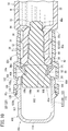
- the cap 16c has a cap body 42a, a cover member 80c that covers the cap body 42a, and a distal-end cover member 100 provided on the distal end side of the cover member 80c.
- the cover member 80c is formed in a cylindrical shape, and is made of a resin material having no transparency (substantially opaque resin material).
- the cover member 80c has a cylindrical main body 82c that covers the cap body 42a.
- An opening 102 for exposing (projecting) the cap body 42a from the cylindrical main body 82c is formed at the distal end of the cylindrical main body 82c.
- the cylindrical main body 82c has a cylindrical first cover portion 86c that covers the base 44, and a cylindrical second cover portion 88c that extends from the proximal end of the first cover portion 86c in the proximal direction.
- Two through holes 104 and two locking projections 106 for locking the distal-end cover member 100 are formed at the distal end section of the inner peripheral surface of the first cover portion 86c.
- the number of through holes 104 and the number of locking projections 106 may be one or three or more, respectively.
- Each through hole 104 is formed in a rectangular shape, and extends along the circumferential direction of the cylindrical main body 82c. These through holes 104 face each other.
- the length of each locking projection 106 along the circumferential direction is slightly shorter than the length of the through hole 104 along the circumferential direction.
- Each locking projection 106 has a first contact surface 106a continuous with a distal-side wall surface defining the through hole 104, a second contact surface 106b which extends from the first contact surface 106a in the distal direction so as to be parallel to the axis of the cylindrical main body 82c, and an inclined surface 106c which is inclined radially outward in the distal direction from the distal end of the second contact surface 106b.
- the inner diameter of the second cover portion 88c is smaller than the inner diameter of the first cover portion 86c.
- the outer diameter of the second cover portion 88c is smaller than the outer diameter of the first cover portion 86c.
- the second cover portion 88c covers the outer surface of the cylindrical portion 24a in a state where the cap body 42a is attached to the cylindrical portion 24a.
- the inner surface of the second cover portion 88c contacts the protruding end surface of the annular protrusion 39.
- engagement tabs 108 (engagement portions) which contact the proximal end surface (proximal stepped surface) of the base 44 are provided at the joint part between the first cover portion 86c and the second cover portion 88c at regular intervals in the circumferential direction of the cylindrical main body 82c. That is, a predetermined space is formed between the engagement tabs 108 that are adjacent to each other in the circumferential direction.
- Each engagement tab 108 extends in the distal direction from the inner surface of the cylindrical main body 82c so as to be inclined radially inward with respect to the axis of the cylindrical main body 82c, and is elastically deformable in the radial direction of the cylindrical main body 82c.
- the diameter of a central hole 110 formed by the inner ends (tip surfaces) of the multiple engagement tabs 108 is smaller than the outer diameter of the base body 50.
- the engagement tabs 108 can be engaged with the base 44 of the cap body 42a so as to prevent detachment of the cap body 42a from the cover member 80c in the proximal direction while allowing the cap body 42a to move in the distal direction with respect to the cover member 80c.
- the distal-end cover member 100 has a substantially U-shaped vertical cross section, and is attached to the opening 102 of the cover member 80c.
- the distal-end cover member 100 covers the cap body 42a so that a user manipulating the cap 16c together with the cover member 80c cannot touch the cap body 42a. That is, the distal-end cover member 100 has a contact preventing function.
- the distal-end cover member 100 also has a function as a detachment preventing portion that prevents the cap body 42a from being detached from the opening 102 of the cover member 80c.
- the distal-end cover member 100 has: an annular portion 112 which has a proximal end section engaged with the distal end section of the cover member 80c such that the annular portion 112 extends in the distal direction from the opening 102 of the cylindrical main body 82c; and a distal-end wall 114 provided at the distal end of the annular portion 112.
- the inner diameter of the annular portion 112 is constant from the distal end to the proximal end, and is greater than the outer diameter of the base 44.
- the annular portion 112 includes an annular peripheral wall 118 on the distal end side, and a cylindrical engagement extending portion 120 extending from the proximal end of the annular peripheral wall 118 in the proximal direction.
- the annular peripheral wall 118 and the distal-end wall 114 define a receiving space 121 (see Fig. 10 ) that can receive at least a part of the base 44.
- An annular locking tab 122 that is to contact the first contact surfaces 106a of the locking projections 106 of the cover member 80c is provided in an area of the outer peripheral surface of the engagement extending portion 120 corresponding to the through holes 104 of the cover member 80c.
- the outer diameter of the locking tab 122 is greater than the distance between the locking projections 106.
- An annular groove 124 into which the protruding ends of the locking projections 106 are inserted is formed on the outer peripheral surface of the engagement extending portion 120 on the distal end side of the locking tab 122.
- Second contact surfaces 106b which are protruding end surfaces of the locking projections 106 contact the bottom surface of the annular groove 124. Note that a wall surface of the annular groove 124 on the proximal end side is defined by the locking tab 122.
- An annular positioning protrusion 126 that is to be in contact with or in proximity to the distal end surface of the cover member 80c is provided at the proximal end section of the outer peripheral surface of the annular peripheral wall 118.
- the positioning protrusion 126 has a triangular cross section. In other words, the positioning protrusion 126 has an inclined surface 126a that is inclined outward in the proximal direction on the distal end side. Accordingly, when the prefilled syringe 12C is inserted into an insertion tube or the like used for transporting the prefilled syringe 12C, the positioning protrusion 126 can be prevented from being caught on the edge of an opening of the insertion tube.
- the distal-end cover member 100 is integrally formed using a transparent resin material. That is, the annular peripheral wall 118 serves as a view allowing portion 128 for allowing the inside of the receiving space 121 to be visible.
- the cover member 80c is made of a transparent resin material
- the transparency of the distal-end cover member 100 is set higher than the transparency of the cover member 80c.
- the user can view the inside of the distal-end cover member 100 more clearly than the inside of the cover member 80c from the outside of the cap 16c.
- the distal-end cover member 100 is colorless in the present embodiment, it may be colored.
- the distal-end wall 114 can contact the distal end of the cap body 42a so as to prevent the cap body 42a from being detached from the cover member 80c in the distal direction.
- the base body 50 of the cap body 42a is located in a first position which is closer to the proximal end than the opening 102 of the cylindrical main body 82c in an unopened state of the cap 16c, as shown in Fig. 10 .
- the distal end of the cap body 42a is located closer to the proximal end than the opening 102 of the cylindrical main body 82c and within the engagement extending portion 120 of the distal-end cover member 100. Accordingly, the outer periphery of the base 44 is enclosed by the substantially opaque cylindrical main body 82c and is invisible from the outside.
- the insertion portion 46a is being attached to the cylindrical portion 24a, and therefore, the first sealing section 56 liquid-tightly seals the distal end section of the flow path 32 of the cylindrical portion 24a, the second sealing section 58a liquid-tightly seals the proximal end section of the flow path 32 of the cylindrical portion 24a, and the third sealing section 62 liquid-tightly seals the intermediate section 60 of the flow path 32 of the cylindrical portion 24a.
- the cover member 80c is pulled out from the barrel body 14.
- the cap body 42a is pushed by the engagement tabs 108 in the distal direction, so that the insertion portion 46a is detached from the cylindrical portion 24a.
- the cap 16c is opened.
- the distal end section of the cylindrical portion 24a is inserted into the second cover portion 88c from the opening on the proximal end side of the cylindrical main body 82c.
- the distal end section of the cylindrical portion 24a contacts the third sealing section 62 (contact portion 130) of the cap body 42a.
- the cap body 42a in the first position is pressed by the cylindrical portion 24a and displaces in the distal direction with respect to the cover member 80c due to the contact between the contact portion 130 of the cap body 42a and the distal end of the cylindrical portion 24a, so that the base 44 protrudes from the opening 102 on the distal end side of the cover member 80c in the distal direction.
- the proximal end of the cylindrical main body 82c approaches the shoulder 28 of the barrel body 14.
- the cap 16c which has been opened is reattached to the barrel body 14.
- the cap body 42a is located in the second position where the base 44 is received in the receiving space 121 formed by the annular peripheral wall 118 and the distal-end wall 114. Therefore, the outer periphery of the base 44 is visible from the outside through the view allowing portion 128 of the distal-end cover member 100.
- the cap body 42a displaces to the second position from the first position where the cap body 42a is covered by the substantially opaque cylindrical main body 82c, by which the outer periphery of the base 44 is visible through the view allowing portion 128.
- the distal-end cover member 100 is made of a transparent material, and the whole of the annular peripheral wall 118 serves as the view allowing portion 128. Thus, the cap body 42a is visible through the view allowing portion 128 with a simple configuration.
- the view allowing portion 128 may be a transparent portion formed in at least a part of the annular peripheral wall 118. That is, the annular peripheral wall 118 may have a substantially opaque portion. Further, the view allowing portion 128 may be a window (opening) formed so as to penetrate the annular peripheral wall 118 constituting the distal-end cover member 100. These configurations can also ensure that the cap body 42a is visible through the view allowing portion 128.
Landscapes
- Health & Medical Sciences (AREA)
- Veterinary Medicine (AREA)
- Public Health (AREA)
- General Health & Medical Sciences (AREA)
- Animal Behavior & Ethology (AREA)
- Life Sciences & Earth Sciences (AREA)
- Hematology (AREA)
- Heart & Thoracic Surgery (AREA)
- Biomedical Technology (AREA)
- Anesthesiology (AREA)
- Engineering & Computer Science (AREA)
- Vascular Medicine (AREA)
- Pharmacology & Pharmacy (AREA)
- Infusion, Injection, And Reservoir Apparatuses (AREA)
Abstract
Description
- The present invention relates to a syringe and a prefilled syringe in which a cap body made of an elastic material is attached to a cylindrical portion of a barrel body.
-
U.S. Patent No. 4,172,457 discloses a syringe which includes: a barrel body having a body portion which can be filled with a drug solution, and a cylindrical portion protruding from the body portion in a distal direction; and a cap inserted into the cylindrical portion. In this syringe, the outer peripheral surface of the cap is in contact with the inner peripheral surface of the cylindrical portion at a proximal end section of the cylindrical portion. - In the abovementioned conventional technology, when the internal pressure of the body portion of the barrel body becomes higher than the external pressure, the drug solution filled in the body portion may enter a gap between a female luer section positioned closer to a distal end than the proximal end section of the cylindrical portion and the cap, and may adhere to the inner peripheral surface of the female luer section.
- When a male luer section of another medical device (e.g., a syringe) is inserted into the female luer section with the drug solution adhering to the inner peripheral surface of the female luer section, the drug solution enters into a gap between the outer peripheral surface of the male luer section and the inner peripheral surface of the female luer section. In this state, the engagement between the female luer section and the male luer section may become loose, which may cause a leakage of the drug solution.
- The present invention has been made in view of such a problem, and aims to provide a syringe and a prefilled syringe that can prevent a drug solution from adhering to the inner peripheral surface of a female luer section, and can prevent a leakage of the solution in a state where a male luer section is engaged with the female luer section.
- In order to achieve the above object, a syringe according to the present invention includes: a barrel body including a body portion that is hollow and that is capable of being filled with a drug solution, and a cylindrical portion that protrudes in a distal direction from a distal end of the body portion and that includes an opening open at a distal end thereof, the cylindrical portion defining a flow path that connects an inside of the body portion and the opening; and a cap including a cap body that is attached to the cylindrical portion and that is made of an elastic material, in which the cylindrical portion includes a female luer section that has an inner diameter reduced in a proximal direction from the opening and that is engageable with a male luer section of another medical device, and a proximal end section that connects the female luer section and the body portion, the cap body includes a base located closer to the distal end than the opening in a state where the cap body is attached to the cylindrical portion, and an insertion portion that protrudes from the base in a proximal direction and that is to be inserted into the cylindrical portion, the insertion portion of the cap body includes a first sealing section that is provided at a distal end of the insertion portion and that has an outer diameter greater than a diameter of the opening in a natural state where the cap body is not attached to the cylindrical portion, and a second sealing section that is provided at a proximal end of the insertion portion and that has an outer diameter greater than an inner diameter of the proximal end section of the cylindrical portion in the natural state, and when the cap body is attached to the cylindrical portion, the first sealing section seals a distal end section of the flow path in a liquid-tight manner by being compressed radially inward by an inner peripheral surface constituting the opening of the cylindrical portion, and the second sealing section seals a proximal end section of the flow path in a liquid-tight manner by being compressed radially inward by an inner peripheral surface of the proximal end section of the cylindrical portion.
- According to such a configuration, the second sealing section of the cap body seals the proximal end section of the flow path of the cylindrical portion in a liquid-tight manner, whereby the drug solution in the barrel body can be prevented from entering into the cylindrical portion. Thus, adherence of the drug solution to the inner peripheral surface of the female luer section can be prevented. Accordingly, when a male luer section of another medical device is inserted into the female luer section, loosening of engagement between the female luer section and the male luer section can be prevented. As a result, a leakage of the solution in the state where the male luer section is engaged with the female luer section can be prevented. In addition, the first sealing section of the cap body seals the distal end section of the flow path of the cylindrical portion in a liquid-tight manner, whereby intrusion of bacteria into the barrel body from outside can be prevented.
- In the syringe described above, the cap body may have a proximal-end protruding portion protruding in the proximal direction from the insertion portion, and when the cap body is attached to the cylindrical portion, the proximal-end protruding portion may be disposed within a distal end section of the body portion.
- Meanwhile, when the drug solution enters the cylindrical portion having a smaller inner diameter than the body portion during, for example, a freeze-drying process of the drug solution in the syringe, the drug solution within the cylindrical portion may not be effectively freeze-dried, because the thermal conductivity and drying efficiency are different between the cylindrical portion and the body portion. According to the configuration described above, the drug solution in the body portion can be reliably prevented from entering the cylindrical portion by the proximal-end protruding portion, so that the drug solution can be freeze-dried effectively.
- In the syringe described above, the proximal-end protruding portion may be formed to protrude toward a proximal end in a tapered manner.
- According to such a configuration, the internal pressure of the body portion can be distributed in a direction intersecting with the axial direction of the cap body, whereby, even if the internal pressure of the body portion increases, detachment of the cap body from the cylindrical portion can be prevented.
- In the syringe described above, the proximal end section of the cylindrical portion may include an annular protruding section that is formed such that the inner peripheral surface of the proximal end section protrudes radially inward and that compresses the second sealing section radially inward, the cap body may include an expanded portion on a proximal end of the second sealing section, the expanded portion having an outer diameter greater than that of the second sealing section, and when the cap body is attached to the cylindrical portion, a distal end of the expanded portion may be engaged with a proximal end of the annular protruding section.
- According to such a configuration, the distal end of the expanded portion engages with the proximal end of the annular protruding section, which can prevent the cap body from dropping from the cylindrical portion.
- In the syringe described above, the proximal end section of the cylindrical portion may have an annular recess formed such that the inner peripheral surface of the proximal end section is recessed radially outward, the second sealing section may have an outer diameter greater than an inner diameter of the annular recess, the insertion portion may have a reduced portion at a distal end of the second sealing section, the reduced portion having an outer diameter smaller than that of the second sealing section, and when the cap body is attached to the cylindrical portion, the second sealing section may be compressed radially inward by the annular recess, and the distal end of the second sealing section may be engaged with a distal end of the annular recess.
- According to such a configuration, the distal end of the second sealing section engages with the distal end of the annular recess, which can prevent the cap body from dropping from the cylindrical portion.
- In the syringe described above, the cap body may include, between the first sealing section and the second sealing section, an intermediate section having an outer diameter smaller than an inner diameter of the female luer section.
- According to such a configuration, the intermediate section is not compressed by the female luer section when the cap body is attached to the cylindrical portion. Therefore, it is possible to prevent the cap body from being tightly fitted into the cylindrical portion, whereby the cap body can be easily removed from the cylindrical portion.
- In the syringe described above, the cap body may include, between the intermediate section and the second sealing section, a third sealing section having an outer diameter greater than an inner diameter of the cylindrical portion in the natural state, and the third sealing section may seal the flow path in a liquid-tight manner by being compressed radially inward by the inner peripheral surface of the cylindrical portion.
- According to such a configuration, it is possible to reliably prevent the drug solution from entering the female luer section while preventing the cap body from being tightly fitted into the cylindrical portion.
- In the syringe described above, the cap may further include a cover member that is cylindrical, the cover member being made of a material harder than the cap body and having an engagement portion to be engaged with the base of the cap body, and the cover member may be attached to the cap body so as to cover at least a part of an outer peripheral surface of the base due to an engagement between the engagement portion and the base.
- According to such a configuration, the cover member made of a hard material functions as a grip, whereby the cap body can be easily removed from the cylindrical portion.
- In the syringe described above, the cover member may include a first cover portion that is cylindrical, the first cover portion having the engagement portion and covering the outer peripheral surface of the base, and a second cover portion that extends in a proximal direction from the first cover portion and that covers an outer peripheral surface of the cylindrical portion.
- According to such a configuration, the second cover portion covers the outer peripheral surface of the cylindrical portion, and thus, it is possible to prevent the cylindrical portion from being damaged by an impact during transportation or storage of the syringe.
- In the syringe described above, the second cover portion may have a female screw section on an inner peripheral surface, and the cylindrical portion may have a screw portion that is screwed to the female screw section on the outer peripheral surface.
- According to such a configuration, when the cover member is rotated with respect to the cylindrical portion to remove the cap body from the cylindrical portion, the movement speed of the cap body in the axial direction can be limited. Therefore, when the cap body is removed from the cylindrical portion, the drug solution (drug) in the body portion can be prevented from scattering to the outside.
- In the syringe described above: the cover member may include a cover main body that has the engagement portion and that has an opening on a distal end thereof, the cover main body being made of a substantially opaque material, and a distal-end cover member attached to the opening of the cover main body; the distal-end cover member may include an annular peripheral wall extending in a distal direction from the opening of the cover main body, a distal-end wall provided on a distal end of the annular peripheral wall, and a receiving space defined by the annular peripheral wall and the distal-end wall and capable of receiving at least a part of the base; the annular peripheral wall may have a view allowing portion for allowing an inside of the receiving space to be visible; the insertion portion of the cap body may have a contact portion located closer to a proximal end than the first sealing section and having an outer diameter greater than an inner diameter of the opening of the cylindrical portion; the cap body may be displaceable along an axial direction of the cover member within the cover member from a first position where the base is located within the cover main body to a second position where at least a part of the base protrudes into the receiving space from the opening of the cover main body; the engagement portion may be engageable with the base of the cap body so as to allow movement of the cap body with respect to the cover member in a distal direction, while preventing detachment of the cap body from the cover member in a proximal direction; the distal-end wall may be contactable to a distal end of the cap body so as to prevent detachment of the cap body from the cover member in the distal direction; the first sealing section may seal the distal end section of the flow path in a liquid-tight manner, and the second sealing section may seal the proximal end section of the flow path in a liquid-tight manner, in a state where the cap body is located in the first position; and the cap body in the first position may displace to the second position so that an outer periphery of the base is visible through the view allowing portion of the annular peripheral wall, due to a contact between the contact portion of the insertion portion and a distal end section of the cylindrical portion.
- According to such a configuration, the cap body displaces to the second position from the first position where the cap body is covered by the substantially opaque cover main body, by which the outer periphery of the base of the cap body is visible through the view allowing portion. Thus, even when the cap body once removed from the cylindrical portion is reattached to the cylindrical portion (recapped), a user can easily and reliably identify whether the cap is unopened or whether the cap is opened.
- In the syringe described above, the view allowing portion may include a transparent portion formed in at least a part of the annular peripheral wall.
- The configuration described above can ensure that the cap body is visible through the view allowing portion.
- In the syringe described above, the distal-end cover member may be made of a transparent material, and the annular peripheral wall may entirely serve as the view allowing portion.
- According to such a configuration, the cap body is visible through the view allowing portion with a simple configuration.
- A prefilled syringe according to the present invention includes: the syringe described above; a drug solution filled in the body portion; and a gasket that is slidable in an axial direction within the body portion in a liquid-tight manner.
- According to such a configuration, a prefilled syringe having an effect similar to the effect of the abovementioned syringe can be obtained.
- According to the present invention, since the second sealing section of the cap body seals the proximal end section of the flow path of the cylindrical portion in a liquid-tight manner, adherence of the drug solution to the inner peripheral surface of the female luer section can be prevented, whereby leakage of the solution in a state where the male luer section is engaged with the female luer section can be prevented.
-
-
Fig. 1 is a longitudinal sectional view of a prefilled syringe according to a first embodiment of the present invention. -
Fig. 2A is an exploded longitudinal sectional view of a distal end section of the syringe inFig. 1 , andFig. 2B is a longitudinal sectional view of a distal end section of the prefilled syringe inFig. 1 . -
Fig. 3 is an exploded perspective view of the distal end section of the prefilled syringe inFig. 1 . -
Fig. 4 is a longitudinal sectional view, a part of which is omitted, showing a state in which a male luer section of another medical device is engaged with a female luer section of the syringe inFig. 1 . -
Fig. 5A is a longitudinal sectional view of a distal end section of a prefilled syringe provided with a cap body according to a first modification, andFig. 5B is a longitudinal sectional view of a distal end section of a prefilled syringe provided with a cap body according to a second modification. -
Fig. 6A is an exploded longitudinal sectional view of a distal end section of a syringe provided with a cap body according to a third modification, andFig. 6B is a longitudinal sectional view of a distal end section of a prefilled syringe in which the cap body inFig. 6A is attached to a cylindrical portion. -
Fig. 7 is a longitudinal sectional view of a distal end section of a prefilled syringe according to a second embodiment of the present invention. -
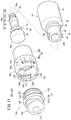
Fig. 8 is an exploded perspective view of the distal end section of the prefilled syringe inFig. 7 . -
Fig. 9A is a plan view of a distal end section of a prefilled syringe provided with a cover member according to a modification, andFig. 9B is a longitudinal sectional view of the distal end section of the prefilled syringe shown inFig. 9A . -
Fig. 10 is a longitudinal sectional view of a distal end section of a prefilled syringe according to a third embodiment of the present invention. -
Fig. 11 is an exploded perspective view of the distal end section of the prefilled syringe inFig. 10 . -
Fig. 12A is a longitudinal sectional view showing a state where a cap is removed from a cylindrical portion inFig. 10 , andFig. 12B is a longitudinal sectional view showing a state where the cap is recapped on the cylindrical portion. - Preferred embodiments of a syringe and a prefilled syringe according to the present invention will be described below with reference to the accompanying drawings.
- As shown in
Fig. 1 , aprefilled syringe 12A includes asyringe 10A having abarrel body 14 and acap 16a, a drug solution M (drug) filled in thebarrel body 14, agasket 18 which is inserted into thebarrel body 14 in a slidable manner, and apusher 20 connected to thegasket 18. - The
barrel body 14 has ahollow body portion 22 which can be filled with the drug solution M, acylindrical portion 24a protruding in a distal direction from a distal end section of thebody portion 22, and aflange 26 provided at a proximal end section of thebody portion 22. Thebody portion 22, thecylindrical portion 24a, and theflange 26 are integrally formed. - The material constituting the
barrel body 14 is not particularly limited, and examples thereof include: a resin material including polyolefin such as polypropylene, polyurethane, polyethylene, cyclic polyolefin, or polymethylpentene 1, polyester, nylon, polycarbonate, polymethyl methacrylate (PMMA), polyether imide (PEI), polyethersulfone, polyether ether ketone (PEEK), fluororesin, polyphenylene sulfide (PPS), or polyacetal resin (POM); a metal material such as stainless; and glass. - The
body portion 22 is formed into a cylindrical shape and extends in an axial direction. Ashoulder 28 whose diameter is reduced toward the proximal end of thecylindrical portion 24a is formed at the distal end section of thebody portion 22. As shown inFig. 2A , thecylindrical portion 24a has anopening 30 that is open at the distal end, and defines aflow path 32 that connects the inside of thebody portion 22 and theopening 30. InFig. 4 , thecylindrical portion 24a has an inner diameter reduced in a proximal direction from theopening 30, and includes afemale luer section 34 that can be engaged with amale luer section 302 of another medical device 300 (another syringe) and aproximal end section 36 that connects thefemale luer section 34 and thebody portion 22 to each other. - As shown in
Figs. 2A and 2B , theproximal end section 36 of thecylindrical portion 24a has an annular protrudingsection 38 formed such that the inner peripheral surface of theproximal end section 36 protrudes radially inward. The annular protrudingsection 38 compresses radially inward a later-describedsecond sealing section 58a which constitutes thecap 16a. InFigs. 2A to 3 , anannular protrusion 39 is provided on the outer peripheral surface of theproximal end section 36 of thecylindrical portion 24a. A male screw section 40 (screw section) to be screwed to a female screw section 304 (seeFig. 4 ) of anothermedical device 300 is provided on the outer peripheral surface of thecylindrical portion 24a. - In
Fig. 1 , thegasket 18 is slidable in the axial direction within thebarrel body 14 in a liquid-tight manner, and delivers the drug solution M filled in thebarrel body 14. The tip of thepusher 20 is connected to thegasket 18. - As shown in
Figs. 2A to 3 , thecap 16a has acap body 42a which is made of an elastic material and which is attached to thecylindrical portion 24a. Rubber or a synthetic resin elastomer may be used as a material constituting thecap body 42a. Examples of usable rubber include isoprene rubber, butyl rubber, latex rubber, and silicone rubber. Examples of usable synthetic resin elastomer include a styrene elastomer and an olefin elastomer. - The
cap body 42a has a base 44 which is located closer to the distal end than theopening 30 in a state where thecap body 42a is attached to thecylindrical portion 24a, aninsertion portion 46a which protrudes in the proximal direction from thebase 44 and which is to be inserted into thecylindrical portion 24a, and a proximal-end protruding portion 48a which protrudes in the proximal direction from theinsertion portion 46a. - The
base 44 has abase body 50 which is columnar and which defines a portion of thecap body 42a having the maximum outer diameter thereof, a small-diameterintermediate section 52 provided on the proximal end surface of thebase body 50, and a large-diameterintermediate section 54 provided on the proximal end surface of the small-diameterintermediate section 52. The outer diameter of the small-diameterintermediate section 52 is smaller than the outer diameter of the large-diameterintermediate section 54. The outer diameter of the large-diameterintermediate section 54 is greater than the diameter of theopening 30 of thecylindrical portion 24a. When thecap body 42a is attached to thecylindrical portion 24a, the proximal end surface of the large-diameterintermediate section 54 is in contact with the distal end surface of thecylindrical portion 24a. It is to be noted, however, that the proximal end surface of the large-diameterintermediate section 54 may be in proximity to the distal end surface of thecylindrical portion 24a, when thecap body 42a is attached to thecylindrical portion 24a. - The
insertion portion 46a includes afirst sealing section 56, asecond sealing section 58a, anintermediate section 60, and athird sealing section 62. Thefirst sealing section 56 is provided on the proximal end surface of the large-diameterintermediate section 54. In a natural state in which thecap body 42a is not attached to thecylindrical portion 24a, thefirst sealing section 56 is provided at the distal end of theinsertion portion 46a and has an outer diameter greater than the diameter of theopening 30. When thecap body 42a is attached to thecylindrical portion 24a, thefirst sealing section 56 is compressed radially inward by the inner peripheral surface that defines theopening 30 of thecylindrical portion 24a, thereby sealing the distal end section of theflow path 32 in a liquid-tight manner (seeFig. 2B ). - In the natural state, the
second sealing section 58a is provided at the proximal end of theinsertion portion 46a, and has an outer diameter greater than the inner diameter of the proximal end section 36 (annular protruding section 38) of thecylindrical portion 24a. When thecap body 42a is attached to thecylindrical portion 24a, thesecond sealing section 58a is compressed radially inward by the inner peripheral surface of the proximal end section 36 (annular protruding section 38) of thecylindrical portion 24a, thereby sealing the proximal end section of theflow path 32 in a liquid-tight manner. - The
intermediate section 60 is provided between thefirst sealing section 56 and thesecond sealing section 58a, and has a constant outer diameter over the entire length. The outer diameter of theintermediate section 60 is smaller than the minimum inner diameter of thefemale luer section 34. In other words, when thecap body 42a is attached to thecylindrical portion 24a, a predetermined gap S is formed between theintermediate section 60 and the female luer section 34 (seeFig. 2B ). - The
third sealing section 62 is provided between theintermediate section 60 and thesecond sealing section 58a, and has an outer diameter greater than the inner diameter of the proximal end section 36 (annular protruding section 38) of thecylindrical portion 24a in the natural state. When thecap body 42a is attached to thecylindrical portion 24a, thethird sealing section 62 is compressed radially inward by the inner peripheral surface of thecylindrical portion 24a, thereby sealing theflow path 32 in a liquid-tight manner (seeFig. 2B ). Thethird sealing section 62 is a portion having the maximum outer diameter of theinsertion portion 46a. - When the
cap body 42a is attached to thecylindrical portion 24a, the proximal-end protruding portion 48a is disposed within the distal end section of the body portion 22 (seeFig. 2B ). Thecap body 42a has an expandedportion 64 having an outer diameter greater than that of thesecond sealing section 58a on the proximal end side of thesecond sealing section 58a. When thecap body 42a is attached to thecylindrical portion 24a, the distal end of the expandedportion 64 engages with the proximal end of the annular protrudingsection 38. The proximal end surface of the proximal-end protruding portion 48a is a flat surface. - Next, the operation of the
prefilled syringe 12A according to the present embodiment configured as described above will be described. - In the present embodiment, the drug solution M filled in the
body portion 22 of theprefilled syringe 12A shown inFig. 1 is freeze-dried. Thereafter, thecap body 42a is removed from thecylindrical portion 24a, and then, as shown inFig. 4 , themale screw section 40 of thecylindrical portion 24a is threaded into thefemale screw section 304 of the othermedical device 300, whereby themale luer section 302 of the othermedical device 300 is engaged with thefemale luer section 34 of thecylindrical portion 24a. At this time, the outer peripheral surface of themale luer section 302 contacts the inner peripheral surface of thefemale luer section 34. Then, a drug solution Ma filled in the othermedical device 300 and the dry powder drug D (freeze-dried drug solution M) are mixed with each other, and the dry powder drug D is dissolved into the drug solution Ma. Thus, a desired drug solution is obtained. - It is to be noted that, in the present embodiment, a desired drug solution may be obtained by mixing the drug solution M in the
prefilled syringe 12A that has not been freeze-dried with the drug solution Ma in themedical device 300. - In this case, the
prefilled syringe 12A according to the present embodiment has the following effects. - When the
cap body 42a is attached to thecylindrical portion 24a, thesecond sealing section 58a of thecap body 42a is compressed radially inward by the inner peripheral surface of theproximal end section 36 of thecylindrical portion 24a, thereby sealing the proximal end section of theflow path 32 of thecylindrical portion 24a in a liquid-tight manner. Therefore, it is possible to prevent the drug solution M in thebarrel body 14 from entering thecylindrical portion 24a. Thus, adherence of the drug solution M to the inner peripheral surface of thefemale luer section 34 can be prevented. - Accordingly, it is possible to prevent the engagement between the
female luer section 34 and themale luer section 302 from becoming loose when themale luer section 302 of the othermedical device 300 is inserted into thefemale luer section 34. As a result, a leakage of the solution in the state where themale luer section 302 is engaged with thefemale luer section 34 can be prevented. - In addition, the
first sealing section 56 provided at the distal end of theinsertion portion 46a of thecap body 42a is compressed radially inward by the inner peripheral surface that defines theopening 30 of thecylindrical portion 24a, thereby sealing the distal end section of theflow path 32 of thecylindrical portion 24a in a liquid-tight manner. Therefore, intrusion of bacteria into thebarrel body 14 from the outside can be prevented. - Meanwhile, when the drug solution M enters the
cylindrical portion 24a having a smaller inner diameter than thebody portion 22 during a freeze-drying process of the drug solution M in thesyringe 10A, the drug solution M within thecylindrical portion 24a may not be effectively freeze-dried, because the thermal conductivity and drying efficiency are different between thecylindrical portion 24a and thebody portion 22. - On the other hand, the
cap body 42a has the proximal-end protruding portion 48a protruding in the proximal direction from theinsertion portion 46a, and when thecap body 42a is attached to thecylindrical portion 24a, the proximal-end protruding portion 48a is located within the distal end section of thebody portion 22. This configuration can reliably prevent the drug solution M in thebody portion 22 from entering thecylindrical portion 24a by the proximal-end protruding portion 48a, so that the drug solution M can be freeze-dried effectively. - The
proximal end section 36 of thecylindrical portion 24a has the annular protrudingsection 38 which is formed such that the inner peripheral surface of theproximal end section 36 protrudes radially inward, the annular protrudingsection 38 compressing thesecond sealing section 58a radially inward. Thecap body 42a has the expandedportion 64 having the outer diameter greater than that of thesecond sealing section 58a on the proximal end side of thesecond sealing section 58a. When thecap body 42a is attached to thecylindrical portion 24a, the distal end of the expandedportion 64 is engaged with the proximal end of the annular protrudingsection 38, which can prevent thecap body 42a from dropping from thecylindrical portion 24a. - The
cap body 42a has theintermediate section 60 having an outer diameter smaller than the inner diameter of thefemale luer section 34 between thefirst sealing section 56 and thesecond sealing section 58a. With this configuration, when thecap body 42a is attached to thecylindrical portion 24a, theintermediate section 60 is not compressed by thefemale luer section 34. Therefore, it is possible to prevent thecap body 42a from being tightly fitted into thecylindrical portion 24a, whereby thecap body 42a can be easily removed from thecylindrical portion 24a. - The
cap body 42a has, between theintermediate section 60 and thesecond sealing section 58a, thethird sealing section 62 having an outer diameter greater than the inner diameter of thecylindrical portion 24a in the natural state. Thethird sealing section 62 is compressed radially inward by the inner peripheral surface of thecylindrical portion 24a, thereby sealing theflow path 32 of thecylindrical portion 24a in a liquid-tight manner. Accordingly, it is possible to reliably prevent the drug solution M from entering thefemale luer section 34 while preventing thecap body 42a from being tightly fitted into thecylindrical portion 24a. - The
cap 16a is not limited to have the configuration described above. As shown inFig. 5A , acap body 42b constituting thecap 16a may have a proximal-end protruding portion 48b that protrudes toward the proximal end in a tapered manner. The proximal-end protruding portion 48b is formed in a substantially hemispherical shape. That is, the outer surface of the proximal-end protruding portion 48b has acurved surface 66. - According to the
cap 16a described above, the internal pressure of thebody portion 22 can be distributed in a direction intersecting with the axial direction of thecap body 42b, whereby, even if the internal pressure of thebody portion 22 increases, detachment of thecap body 42b from thecylindrical portion 24a can be prevented. - As shown in
Fig. 5B , acap body 42c constituting thecap 16a may have a proximal-end protruding portion 48c that protrudes toward the proximal end in a tapered manner. The proximal-end protruding portion 48c is formed in a substantially frusto-conical shape. That is, the outer surface of the proximal-end protruding portion 48c has aninclined surface 68 inclined radially inward in the proximal direction. According to thecap body 42c described above, an effect similar to the effect of thecap body 42b shown inFig. 5A can be obtained. - The proximal-
end protruding portions end protruding portion 48c may be formed into, for example, a substantially triangular based pyramid or a substantially truncated triangular based pyramid. - As shown in
Fig. 6A , theproximal end section 36 of acylindrical portion 24b constituting thebarrel body 14 may have anannular recess 70 formed such that the inner peripheral surface of theproximal end section 36 is recessed radially outward, instead of the annular protrudingsection 38. In this case, acap body 42d constituting thecap 16a has aninsertion portion 46b which includes: asecond sealing section 58b having an outer diameter greater than the inner diameter of theannular recess 70; and a proximal-end protruding portion 48d provided at the proximal end of thesecond sealing section 58b. Theinsertion portion 46b is provided with a reducedportion 74 having an outer diameter smaller than the outer diameter of thesecond sealing section 58b between thesecond sealing section 58b and thethird sealing section 62. Thesecond sealing section 58b is a portion having the maximum outer diameter of theinsertion portion 46b. The proximal-end protruding portion 48d has a configuration similar to that of the proximal-end protruding portion 48c described above. - As shown in
Fig. 6B , when thecap body 42d configured as described above is attached to thecylindrical portion 24b, thesecond sealing section 58b is compressed radially inward by theannular recess 70, and the distal end of thesecond sealing section 58b is engaged with the distal end of theannular recess 70. - According to such a configuration, the distal end of the
second sealing section 58b engages with the distal end of theannular recess 70, which can prevent thecap body 42d from dropping from thecylindrical portion 24b. - Next, a
prefilled syringe 12B provided with asyringe 10B according to a second embodiment of the present invention will be described. In theprefilled syringe 12B according to the second embodiment, the same components as those described in the above embodiment are denoted by the same reference numerals, and the detailed description thereof will be omitted. The same applies to a third embodiment described later. - As shown in
Figs. 7 and8 , thesyringe 10B constituting theprefilled syringe 12B includes abarrel body 14 and acap 16b. Thecap 16b has acap body 42a and acover member 80a that covers thecap body 42a. - The
cover member 80a is made of a material (for example, a resin material) harder than thecap body 42a. Thecover member 80a has a cylindricalmain body 82a having a cylindrical shape, and anengagement portion 84 provided on the inner peripheral surface of the cylindricalmain body 82a. The cylindricalmain body 82a includes a cylindricalfirst cover portion 86a that covers abase 44, and a cylindricalsecond cover portion 88a that extends in the proximal direction from the proximal end of thefirst cover portion 86a. - The overall length of the
first cover portion 86a is longer than the axial length of abase body 50. That is, thefirst cover portion 86a entirely covers the outer peripheral surface of thebase body 50. However, thefirst cover portion 86a only needs to cover at least a part of the outer peripheral surface of thebase body 50. - The
second cover portion 88a covers the outer peripheral surface of thecylindrical portion 24a in a state where thecap body 42a is attached to thecylindrical portion 24a. The proximal end surface of thesecond cover portion 88a faces theshoulder 28 of thebarrel body 14 with a gap therebetween in a state where thecap body 42a is attached to thecylindrical portion 24a. - The
engagement portion 84 is provided at a joint part between thefirst cover portion 86a and thesecond cover portion 88a, and engages with thebase 44 of thecap body 42a. Theengagement portion 84 protrudes radially inward from the inner surface of the cylindricalmain body 82a and circumferentially extends along the entire circumference. That is, theengagement portion 84 is annularly formed. The protruding end of theengagement portion 84 is held between thebase body 50 and the large-diameter intermediate section 54 (seeFig. 7 ). Accordingly, the movement of thecover member 80a in the axial direction with respect to thecap body 42a is restricted. - In the
prefilled syringe 12B configured as described above, a user can remove thecap body 42a from thecylindrical portion 24a by pulling thecap 16b in the distal direction from thebarrel body 14 while holding the outer peripheral surface of thecover member 80a. Therefore, according to theprefilled syringe 12B, thecover member 80a made of a hard material functions as a grip, whereby thecap body 42a can be easily removed from thecylindrical portion 24a. - Further, since the
second cover portion 88a covers the outer peripheral surface of thecylindrical portion 24a, it is possible to prevent thecylindrical portion 24a from being damaged by an impact during transportation or storage of thesyringe 10B (prefilled syringe 12B). - The
cap 16b may include acover member 80b shown inFigs. 9A and 9B instead of thecover member 80a. Thecover member 80b has a cylindricalmain body 82b and anengagement portion 84. As shown inFig. 9B , the cylindricalmain body 82b includes a cylindricalfirst cover portion 86b that covers thebase 44, and a cylindricalsecond cover portion 88b that extends in the proximal direction from the proximal end of thefirst cover portion 86b. Afemale screw section 90 that is screwed to themale screw section 40 of thecylindrical portion 24a is formed on the inner peripheral surface of thesecond cover portion 88b. - In
Fig. 9A , anon-slip portion 92 that functions to prevent a slip of a user's finger is formed on the outer surface of the cylindricalmain body 82b. Thenon-slip portion 92 is formed by providing, in an alternate manner, a plurality ofprojections 92a and recesses 92b which extend along the axial direction of the cylindricalmain body 82b in the circumferential direction. Theprojections 92a and therecesses 92b extend over the entire length of the cylindricalmain body 82b. - The
non-slip portion 92 is not limited to have the configuration in which theprojections 92a and therecesses 92b extending in the axial direction of the cylindricalmain body 82b are provided alternately in the circumferential direction of the cylindricalmain body 82b. For example, a plurality of protrusions or the like protruding from the outer peripheral surface of the cylindricalmain body 82b in the form of a column may be used. - According to the
cap 16b shown inFigs. 9A and 9B , when thecover member 80b is rotated with respect to thecylindrical portion 24a to remove thecap body 42a from thecylindrical portion 24a, the movement speed of thecap body 42a in the axial direction is limited. Therefore, when thecap body 42a is removed from thecylindrical portion 24a, the drug solution M (dry powder drug D) in thebody portion 22 can be prevented from scattering to the outside. - The
syringe 10B may include any one of thecap bodies 42b to 42d described above instead of thecap body 42a. - Next, a
prefilled syringe 12C including asyringe 10C according to a third embodiment of the present invention will be described. - As shown in
Figs. 10 and11 , thesyringe 10C constituting theprefilled syringe 12C includes abarrel body 14 and acap 16c. Thecap 16c has acap body 42a, acover member 80c that covers thecap body 42a, and a distal-end cover member 100 provided on the distal end side of thecover member 80c. - The
cover member 80c is formed in a cylindrical shape, and is made of a resin material having no transparency (substantially opaque resin material). Thecover member 80c has a cylindricalmain body 82c that covers thecap body 42a. Anopening 102 for exposing (projecting) thecap body 42a from the cylindricalmain body 82c is formed at the distal end of the cylindricalmain body 82c. - The cylindrical
main body 82c has a cylindricalfirst cover portion 86c that covers thebase 44, and a cylindricalsecond cover portion 88c that extends from the proximal end of thefirst cover portion 86c in the proximal direction. Two throughholes 104 and two lockingprojections 106 for locking the distal-end cover member 100 are formed at the distal end section of the inner peripheral surface of thefirst cover portion 86c. The number of throughholes 104 and the number of lockingprojections 106 may be one or three or more, respectively. - Each through
hole 104 is formed in a rectangular shape, and extends along the circumferential direction of the cylindricalmain body 82c. These throughholes 104 face each other. The length of each lockingprojection 106 along the circumferential direction is slightly shorter than the length of the throughhole 104 along the circumferential direction. Each lockingprojection 106 has afirst contact surface 106a continuous with a distal-side wall surface defining the throughhole 104, asecond contact surface 106b which extends from thefirst contact surface 106a in the distal direction so as to be parallel to the axis of the cylindricalmain body 82c, and aninclined surface 106c which is inclined radially outward in the distal direction from the distal end of thesecond contact surface 106b. - The inner diameter of the
second cover portion 88c is smaller than the inner diameter of thefirst cover portion 86c. The outer diameter of thesecond cover portion 88c is smaller than the outer diameter of thefirst cover portion 86c. Thesecond cover portion 88c covers the outer surface of thecylindrical portion 24a in a state where thecap body 42a is attached to thecylindrical portion 24a. The inner surface of thesecond cover portion 88c contacts the protruding end surface of theannular protrusion 39. - Multiple (six in
Fig. 11 ) engagement tabs 108 (engagement portions) which contact the proximal end surface (proximal stepped surface) of the base 44 are provided at the joint part between thefirst cover portion 86c and thesecond cover portion 88c at regular intervals in the circumferential direction of the cylindricalmain body 82c. That is, a predetermined space is formed between theengagement tabs 108 that are adjacent to each other in the circumferential direction. Eachengagement tab 108 extends in the distal direction from the inner surface of the cylindricalmain body 82c so as to be inclined radially inward with respect to the axis of the cylindricalmain body 82c, and is elastically deformable in the radial direction of the cylindricalmain body 82c. - The diameter of a
central hole 110 formed by the inner ends (tip surfaces) of themultiple engagement tabs 108 is smaller than the outer diameter of thebase body 50. Theengagement tabs 108 can be engaged with thebase 44 of thecap body 42a so as to prevent detachment of thecap body 42a from thecover member 80c in the proximal direction while allowing thecap body 42a to move in the distal direction with respect to thecover member 80c. - The distal-
end cover member 100 has a substantially U-shaped vertical cross section, and is attached to theopening 102 of thecover member 80c. The distal-end cover member 100 covers thecap body 42a so that a user manipulating thecap 16c together with thecover member 80c cannot touch thecap body 42a. That is, the distal-end cover member 100 has a contact preventing function. The distal-end cover member 100 also has a function as a detachment preventing portion that prevents thecap body 42a from being detached from theopening 102 of thecover member 80c. - The distal-
end cover member 100 has: anannular portion 112 which has a proximal end section engaged with the distal end section of thecover member 80c such that theannular portion 112 extends in the distal direction from theopening 102 of the cylindricalmain body 82c; and a distal-end wall 114 provided at the distal end of theannular portion 112. The inner diameter of theannular portion 112 is constant from the distal end to the proximal end, and is greater than the outer diameter of thebase 44. - The
annular portion 112 includes an annularperipheral wall 118 on the distal end side, and a cylindricalengagement extending portion 120 extending from the proximal end of the annularperipheral wall 118 in the proximal direction. The annularperipheral wall 118 and the distal-end wall 114 define a receiving space 121 (seeFig. 10 ) that can receive at least a part of thebase 44. - An
annular locking tab 122 that is to contact the first contact surfaces 106a of the lockingprojections 106 of thecover member 80c is provided in an area of the outer peripheral surface of theengagement extending portion 120 corresponding to the throughholes 104 of thecover member 80c. The outer diameter of thelocking tab 122 is greater than the distance between the lockingprojections 106. - An
annular groove 124 into which the protruding ends of the lockingprojections 106 are inserted is formed on the outer peripheral surface of theengagement extending portion 120 on the distal end side of thelocking tab 122. Second contact surfaces 106b which are protruding end surfaces of the lockingprojections 106 contact the bottom surface of theannular groove 124. Note that a wall surface of theannular groove 124 on the proximal end side is defined by thelocking tab 122. - An
annular positioning protrusion 126 that is to be in contact with or in proximity to the distal end surface of thecover member 80c is provided at the proximal end section of the outer peripheral surface of the annularperipheral wall 118. Thepositioning protrusion 126 has a triangular cross section. In other words, thepositioning protrusion 126 has aninclined surface 126a that is inclined outward in the proximal direction on the distal end side. Accordingly, when theprefilled syringe 12C is inserted into an insertion tube or the like used for transporting theprefilled syringe 12C, thepositioning protrusion 126 can be prevented from being caught on the edge of an opening of the insertion tube. - The distal-
end cover member 100 is integrally formed using a transparent resin material. That is, the annularperipheral wall 118 serves as aview allowing portion 128 for allowing the inside of the receivingspace 121 to be visible. In a case where thecover member 80c is made of a transparent resin material, the transparency of the distal-end cover member 100 is set higher than the transparency of thecover member 80c. Thus, the user can view the inside of the distal-end cover member 100 more clearly than the inside of thecover member 80c from the outside of thecap 16c. Although the distal-end cover member 100 is colorless in the present embodiment, it may be colored. - The distal-
end wall 114 can contact the distal end of thecap body 42a so as to prevent thecap body 42a from being detached from thecover member 80c in the distal direction. - In the
prefilled syringe 12C configured as described above, thebase body 50 of thecap body 42a is located in a first position which is closer to the proximal end than theopening 102 of the cylindricalmain body 82c in an unopened state of thecap 16c, as shown inFig. 10 . Specifically, the distal end of thecap body 42a is located closer to the proximal end than theopening 102 of the cylindricalmain body 82c and within theengagement extending portion 120 of the distal-end cover member 100. Accordingly, the outer periphery of thebase 44 is enclosed by the substantially opaque cylindricalmain body 82c and is invisible from the outside. Theinsertion portion 46a is being attached to thecylindrical portion 24a, and therefore, thefirst sealing section 56 liquid-tightly seals the distal end section of theflow path 32 of thecylindrical portion 24a, thesecond sealing section 58a liquid-tightly seals the proximal end section of theflow path 32 of thecylindrical portion 24a, and thethird sealing section 62 liquid-tightly seals theintermediate section 60 of theflow path 32 of thecylindrical portion 24a. - When the
cap 16c is removed to open thebarrel body 14, thecover member 80c is pulled out from thebarrel body 14. Thus, as shown inFig. 12A , thecap body 42a is pushed by theengagement tabs 108 in the distal direction, so that theinsertion portion 46a is detached from thecylindrical portion 24a. As a result, thecap 16c is opened. - When the
cap 16c which has been opened is reattached to the barrel body 14 (recapped), the distal end section of thecylindrical portion 24a is inserted into thesecond cover portion 88c from the opening on the proximal end side of the cylindricalmain body 82c. Thus, as shown inFig. 12B , the distal end section of thecylindrical portion 24a contacts the third sealing section 62 (contact portion 130) of thecap body 42a. - Subsequently, when the
cover member 80c and thebarrel body 14 are brought close to each other, thecap body 42a in the first position is pressed by thecylindrical portion 24a and displaces in the distal direction with respect to thecover member 80c due to the contact between thecontact portion 130 of thecap body 42a and the distal end of thecylindrical portion 24a, so that the base 44 protrudes from theopening 102 on the distal end side of thecover member 80c in the distal direction. - Then, the proximal end of the cylindrical
main body 82c approaches theshoulder 28 of thebarrel body 14. Thus, thecap 16c which has been opened is reattached to thebarrel body 14. At this time, thecap body 42a is located in the second position where thebase 44 is received in the receivingspace 121 formed by the annularperipheral wall 118 and the distal-end wall 114. Therefore, the outer periphery of thebase 44 is visible from the outside through theview allowing portion 128 of the distal-end cover member 100. - According to the present embodiment, the
cap body 42a displaces to the second position from the first position where thecap body 42a is covered by the substantially opaque cylindricalmain body 82c, by which the outer periphery of thebase 44 is visible through theview allowing portion 128. Thus, even when thecap body 42a once removed from thecylindrical portion 24a is reattached to thecylindrical portion 24a, the user can easily and reliably identify whether thecap 16c is unopened or opened. - The distal-
end cover member 100 is made of a transparent material, and the whole of the annularperipheral wall 118 serves as theview allowing portion 128. Thus, thecap body 42a is visible through theview allowing portion 128 with a simple configuration. - In the
syringe 10C, theview allowing portion 128 may be a transparent portion formed in at least a part of the annularperipheral wall 118. That is, the annularperipheral wall 118 may have a substantially opaque portion. Further, theview allowing portion 128 may be a window (opening) formed so as to penetrate the annularperipheral wall 118 constituting the distal-end cover member 100. These configurations can also ensure that thecap body 42a is visible through theview allowing portion 128. - It is obvious that the syringe and the prefilled syringe according to the present invention are not limited to the abovementioned embodiments, and can employ various configurations without departing from the scope of the present invention.
Claims (14)
- A syringe comprising:a barrel body including a body portion that is hollow and that is capable of being filled with a drug solution, and a cylindrical portion that protrudes in a distal direction from a distal end of the body portion and that includes an opening open at a distal end of the cylindrical portion, the cylindrical portion defining a flow path that connects an inside of the body portion and the opening; anda cap including a cap body that is attached to the cylindrical portion and that is made of an elastic material, whereinthe cylindrical portion includesa female luer section that has an inner diameter reduced in a proximal direction from the opening and that is engageable with a male luer section of another medical device, anda proximal end section that connects the female luer section and the body portion,the cap body includesa base located closer to the distal end than the opening in a state where the cap body is attached to the cylindrical portion, andan insertion portion that protrudes from the base in a proximal direction and that is to be inserted into the cylindrical portion,the insertion portion of the cap body includesa first sealing section that is provided at a distal end of the insertion portion and that has an outer diameter greater than a diameter of the opening in a natural state where the cap body is not attached to the cylindrical portion, anda second sealing section that is provided at a proximal end of the insertion portion and that has an outer diameter greater than an inner diameter of the proximal end section of the cylindrical portion in the natural state, andwhen the cap body is attached to the cylindrical portion, the first sealing section seals a distal end section of the flow path in a liquid-tight manner by being compressed radially inward by an inner peripheral surface constituting the opening of the cylindrical portion, and the second sealing section seals a proximal end section of the flow path in a liquid-tight manner by being compressed radially inward by an inner peripheral surface of the proximal end section of the cylindrical portion.
- The syringe according to claim 1, wherein
the cap body has a proximal-end protruding portion protruding in the proximal direction from the insertion portion, and
when the cap body is attached to the cylindrical portion, the proximal-end protruding portion is disposed within a distal end section of the body portion. - The syringe according to claim 2, wherein
the proximal-end protruding portion is formed to protrude toward a proximal end in a tapered manner. - The syringe according to any one of claims 1 to 3, wherein
the proximal end section of the cylindrical portion includes an annular protruding section that is formed such that the inner peripheral surface of the proximal end section protrudes radially inward and that compresses the second sealing section radially inward,
the cap body includes an expanded portion on a proximal end of the second sealing section, the expanded portion having an outer diameter greater than an outer diameter of the second sealing section, and
when the cap body is attached to the cylindrical portion, a distal end of the expanded portion is engaged with a proximal end of the annular protruding section. - The syringe according any one of claims 1 to 3, wherein
the proximal end section of the cylindrical portion has an annular recess formed such that the inner peripheral surface of the proximal end section is recessed radially outward,
the second sealing section has an outer diameter greater than an inner diameter of the annular recess,
the insertion portion has a reduced portion at a distal end of the second sealing section, the reduced portion having an outer diameter smaller than an outer diameter of the second sealing section, and
when the cap body is attached to the cylindrical portion, the second sealing section is compressed radially inward by the annular recess, and the distal end of the second sealing section is engaged with a distal end of the annular recess. - The syringe according any one of claims 1 to 5, wherein
the cap body includes, between the first sealing section and the second sealing section, an intermediate section having an outer diameter smaller than an inner diameter of the female luer section. - The syringe according claim 6, wherein
the cap body includes, between the intermediate section and the second sealing section, a third sealing section having an outer diameter greater than an inner diameter of the cylindrical portion in the natural state, and
the third sealing section seals the flow path in a liquid-tight manner by being compressed radially inward by the inner peripheral surface of the cylindrical portion. - The syringe according any one of claims 1 to 7, wherein
the cap further includes a cover member that is cylindrical, the cover member being made of a material harder than the cap body and having an engagement portion to be engaged with the base of the cap body, and
the cover member is attached to the cap body so as to cover at least a part of an outer peripheral surface of the base due to an engagement between the engagement portion and the base. - The syringe according claim 8, wherein
the cover member includes
a first cover portion that is cylindrical, the first cover portion having the engagement portion and covering the outer peripheral surface of the base, and
a second cover portion that extends in a proximal direction from the first cover portion and that covers an outer peripheral surface of the cylindrical portion. - The syringe according claim 9, wherein
the second cover portion has a female screw section on an inner peripheral surface, and
the cylindrical portion has a screw portion that is screwed to the female screw section on the outer peripheral surface. - The syringe according any one of claims 8 to 10, wherein
the cover member includes
a cylindrical main body that has the engagement portion and that has an opening on a distal end of the cylindrical main body, the cylindrical main body being made of a substantially opaque material, and
a distal-end cover member attached to the opening of the cylindrical main body,
the distal-end cover member includes
an annular peripheral wall extending in a distal direction from the opening of the cylindrical main body,
a distal-end wall provided on a distal end of the annular peripheral wall, and
a receiving space defined by the annular peripheral wall and the distal-end wall and capable of receiving at least a part of the base,
the annular peripheral wall has a view allowing portion for allowing an inside of the receiving space to be visible,
the insertion portion of the cap body has a contact portion located closer to a proximal end than the first sealing section and having an outer diameter greater than an inner diameter of the opening of the cylindrical portion,
the cap body is displaceable along an axial direction of the cover member within the cover member from a first position where the base is located within the cylindrical main body to a second position where at least a part of the base protrudes into the receiving space from the opening of the cylindrical main body,
the engagement portion is engageable with the base of the cap body so as to allow movement of the cap body with respect to the cover member in a distal direction, while preventing detachment of the cap body from the cover member in a proximal direction,
the distal-end wall is contactable to a distal end of the cap body so as to prevent detachment of the cap body from the cover member in the distal direction,
the first sealing section seals the distal end section of the flow path in a liquid-tight manner, and the second sealing section seals the proximal end section of the flow path in a liquid-tight manner, in a state where the cap body is located in the first position, and
the cap body in the first position displaces to the second position so that an outer periphery of the base is visible through the view allowing portion of the annular peripheral wall, due to a contact between the contact portion of the insertion portion and a distal end section of the cylindrical portion. - The syringe according to claim 11, wherein
the view allowing portion includes a transparent portion formed in at least a part of the annular peripheral wall. - The syringe according to claim 11, wherein
the distal-end cover member is made of a transparent material, and
the annular peripheral wall entirely serves as the view allowing portion. - A prefilled syringe comprising:the syringe according to any one of claims 1 to 13;a drug solution filled in the body portion; anda gasket that is slidable in an axial direction within the body portion in a liquid-tight manner.
Applications Claiming Priority (2)
| Application Number | Priority Date | Filing Date | Title |
|---|---|---|---|
| JP2017210440 | 2017-10-31 | ||
| PCT/JP2018/040413 WO2019088136A1 (en) | 2017-10-31 | 2018-10-30 | Syringe and prefilled syringe |
Publications (2)
| Publication Number | Publication Date |
|---|---|
| EP3689396A1 true EP3689396A1 (en) | 2020-08-05 |
| EP3689396A4 EP3689396A4 (en) | 2020-08-19 |
Family
ID=66332598
Family Applications (1)
| Application Number | Title | Priority Date | Filing Date |
|---|---|---|---|
| EP18874321.5A Withdrawn EP3689396A4 (en) | 2017-10-31 | 2018-10-30 | Syringe and prefilled syringe |
Country Status (6)
| Country | Link |
|---|---|
| US (1) | US11660402B2 (en) |
| EP (1) | EP3689396A4 (en) |
| JP (1) | JP7179752B2 (en) |
| KR (1) | KR102571984B1 (en) |
| CN (1) | CN111278492B (en) |
| WO (1) | WO2019088136A1 (en) |
Families Citing this family (4)
| Publication number | Priority date | Publication date | Assignee | Title |
|---|---|---|---|---|
| JP7499090B2 (en) * | 2020-07-01 | 2024-06-13 | テルモ株式会社 | Prefilled syringe, syringe assembly, method for manufacturing prefilled syringe, and method for increasing surface area |
| JP7750515B2 (en) * | 2022-01-28 | 2025-10-07 | 株式会社トクヤマデンタル | Closing device for releasably closing the nozzle of a syringe barrel |
| KR102835568B1 (en) | 2023-07-07 | 2025-07-18 | 주식회사 케어솔루션 | Bubble removing apparatus for prefilled syringe |
| CN120437430A (en) * | 2025-05-14 | 2025-08-08 | 南京巴特弗莱医药包装材料有限责任公司 | Protective cap assembly and syringe having the same |
Family Cites Families (15)
| Publication number | Priority date | Publication date | Assignee | Title |
|---|---|---|---|---|
| US4172457A (en) | 1977-10-06 | 1979-10-30 | American Hospital Supply Corporation | Plural component mixing system and method |
| JP2526736Y2 (en) * | 1990-04-23 | 1997-02-19 | 川澄化学工業株式会社 | Body fluid treatment device stopper |
| US5624402A (en) * | 1994-12-12 | 1997-04-29 | Becton, Dickinson And Company | Syringe tip cap |
| US5807345A (en) * | 1995-06-30 | 1998-09-15 | Abbott Laboratories | Luer cap for terminally sterilized syringe |
| JPH0977105A (en) * | 1995-09-06 | 1997-03-25 | Sanshu:Kk | Closure construction for opening of bottle |
| WO2007035746A2 (en) * | 2005-09-20 | 2007-03-29 | Biomerieux, Inc. | Specimen enclosure apparatus and containers and closure devices for the same |
| ES2549165T3 (en) * | 2009-09-30 | 2015-10-23 | Terumo Kabushiki Kaisha | Hypodermic needle set and medication injection device |
| DE102011013792A1 (en) * | 2011-03-03 | 2012-09-06 | Vetter Pharma-Fertigung GmbH & Co. KG | Closure for a powder syringe and powder syringe |
| JP6273087B2 (en) * | 2012-10-25 | 2018-01-31 | 大成化工株式会社 | Syringe |
| CN102961803B (en) * | 2012-10-30 | 2015-01-21 | 无锡耐思生物科技有限公司 | Disposable prefilled syringe |
| CN105517604B (en) * | 2013-09-06 | 2019-11-08 | 泰尔茂株式会社 | Syringe outer cylinder, prefilled syringe and die injection moulding |
| EP3042679B1 (en) * | 2013-09-06 | 2021-10-27 | Terumo Kabushiki Kaisha | Outer tube for syringe and pre-filled syringe |
| JP6491096B2 (en) * | 2013-09-06 | 2019-03-27 | テルモ株式会社 | Syringe outer cylinder and prefilled syringe |
| TWI654004B (en) * | 2014-06-04 | 2019-03-21 | 日商大成化工股份有限公司 | Syringe cap, syringe with needle, and pre-filled syringe formulation |
| JP6889725B2 (en) * | 2016-09-30 | 2021-06-18 | テルモ株式会社 | Cap, syringe assembly and prefilled syringe |
-
2018
- 2018-10-30 CN CN201880069929.6A patent/CN111278492B/en active Active
- 2018-10-30 EP EP18874321.5A patent/EP3689396A4/en not_active Withdrawn
- 2018-10-30 KR KR1020207012138A patent/KR102571984B1/en active Active
- 2018-10-30 WO PCT/JP2018/040413 patent/WO2019088136A1/en not_active Ceased
- 2018-10-30 JP JP2019550433A patent/JP7179752B2/en active Active
-
2020
- 2020-04-30 US US16/862,874 patent/US11660402B2/en active Active
Also Published As
| Publication number | Publication date |
|---|---|
| US20200268982A1 (en) | 2020-08-27 |
| CN111278492A (en) | 2020-06-12 |
| CN111278492B (en) | 2022-06-24 |
| EP3689396A4 (en) | 2020-08-19 |
| KR102571984B1 (en) | 2023-08-29 |
| JP7179752B2 (en) | 2022-11-29 |
| JPWO2019088136A1 (en) | 2020-11-12 |
| US11660402B2 (en) | 2023-05-30 |
| KR20200083466A (en) | 2020-07-08 |
| WO2019088136A1 (en) | 2019-05-09 |
Similar Documents
| Publication | Publication Date | Title |
|---|---|---|
| US11660402B2 (en) | Syringe and prefilled syringe | |
| JP6693871B2 (en) | Adapters for drug delivery devices and methods for mounting said adapters therein | |
| US6520935B1 (en) | Syringe and tip cap assembly | |
| JP2736245B2 (en) | Syringe tip cap | |
| JPWO2018164250A1 (en) | Syringe assembly and prefilled syringe | |
| JPWO2018061948A1 (en) | Cap, syringe assembly and prefilled syringe | |
| JP7241166B2 (en) | Syringe cap, syringe assembly and prefilled syringe | |
| AU2023229546B2 (en) | Syringe cap, syringe assembly, and pre-filled syringe | |
| US20250099731A1 (en) | Connector Assembly for Medical Injection Device | |
| JP7322061B2 (en) | Syringe cap, syringe assembly and prefilled syringe | |
| JP2017143945A (en) | Needleless port and needleless port cap provided therein | |
| EP4212142A1 (en) | Vial adaptor providing audible feedback and connector assembly for medical injection device including vial adaptor | |
| US12397121B2 (en) | Syringe cap, syringe assembly, and prefilled syringe | |
| JP6895446B2 (en) | Prefilled syringes and syringes | |
| JP2016187530A (en) | Syringe plunger, syringe, and prefilled syringe |
Legal Events
| Date | Code | Title | Description |
|---|---|---|---|
| STAA | Information on the status of an ep patent application or granted ep patent |
Free format text: STATUS: THE INTERNATIONAL PUBLICATION HAS BEEN MADE |
|
| PUAI | Public reference made under article 153(3) epc to a published international application that has entered the european phase |
Free format text: ORIGINAL CODE: 0009012 |
|
| STAA | Information on the status of an ep patent application or granted ep patent |
Free format text: STATUS: REQUEST FOR EXAMINATION WAS MADE |
|
| 17P | Request for examination filed |
Effective date: 20200428 |
|
| AK | Designated contracting states |
Kind code of ref document: A1 Designated state(s): AL AT BE BG CH CY CZ DE DK EE ES FI FR GB GR HR HU IE IS IT LI LT LU LV MC MK MT NL NO PL PT RO RS SE SI SK SM TR |
|
| AX | Request for extension of the european patent |
Extension state: BA ME |
|
| A4 | Supplementary search report drawn up and despatched |
Effective date: 20200717 |
|
| RIC1 | Information provided on ipc code assigned before grant |
Ipc: A61M 39/20 20060101ALI20200713BHEP Ipc: A61M 5/31 20060101ALI20200713BHEP Ipc: A61M 5/50 20060101ALI20200713BHEP Ipc: B65D 41/28 20060101ALI20200713BHEP Ipc: B65D 41/04 20060101ALI20200713BHEP Ipc: A61M 5/28 20060101AFI20200713BHEP Ipc: A61J 1/05 20060101ALI20200713BHEP Ipc: A61J 1/20 20060101ALI20200713BHEP Ipc: A61J 1/06 20060101ALI20200713BHEP |
|
| DAV | Request for validation of the european patent (deleted) | ||
| DAX | Request for extension of the european patent (deleted) | ||
| STAA | Information on the status of an ep patent application or granted ep patent |
Free format text: STATUS: THE APPLICATION IS DEEMED TO BE WITHDRAWN |
|
| 18D | Application deemed to be withdrawn |
Effective date: 20210216 |