EP3689282A1 - Drive mechanisms for surgical instruments such as for use in robotic surgical systems - Google Patents
Drive mechanisms for surgical instruments such as for use in robotic surgical systems Download PDFInfo
- Publication number
- EP3689282A1 EP3689282A1 EP20154025.9A EP20154025A EP3689282A1 EP 3689282 A1 EP3689282 A1 EP 3689282A1 EP 20154025 A EP20154025 A EP 20154025A EP 3689282 A1 EP3689282 A1 EP 3689282A1
- Authority
- EP
- European Patent Office
- Prior art keywords
- hub
- surgical instrument
- drive rod
- input
- gear
- Prior art date
- Legal status (The legal status is an assumption and is not a legal conclusion. Google has not performed a legal analysis and makes no representation as to the accuracy of the status listed.)
- Granted
Links
Images









Classifications
-
- A—HUMAN NECESSITIES
- A61—MEDICAL OR VETERINARY SCIENCE; HYGIENE
- A61B—DIAGNOSIS; SURGERY; IDENTIFICATION
- A61B34/00—Computer-aided surgery; Manipulators or robots specially adapted for use in surgery
- A61B34/30—Surgical robots
-
- A—HUMAN NECESSITIES
- A61—MEDICAL OR VETERINARY SCIENCE; HYGIENE
- A61B—DIAGNOSIS; SURGERY; IDENTIFICATION
- A61B34/00—Computer-aided surgery; Manipulators or robots specially adapted for use in surgery
- A61B34/30—Surgical robots
- A61B34/35—Surgical robots for telesurgery
-
- A—HUMAN NECESSITIES
- A61—MEDICAL OR VETERINARY SCIENCE; HYGIENE
- A61B—DIAGNOSIS; SURGERY; IDENTIFICATION
- A61B17/00—Surgical instruments, devices or methods
- A61B17/28—Surgical forceps
- A61B17/29—Forceps for use in minimally invasive surgery
-
- A—HUMAN NECESSITIES
- A61—MEDICAL OR VETERINARY SCIENCE; HYGIENE
- A61B—DIAGNOSIS; SURGERY; IDENTIFICATION
- A61B17/00—Surgical instruments, devices or methods
- A61B17/28—Surgical forceps
- A61B17/29—Forceps for use in minimally invasive surgery
- A61B17/295—Forceps for use in minimally invasive surgery combined with cutting implements
-
- A—HUMAN NECESSITIES
- A61—MEDICAL OR VETERINARY SCIENCE; HYGIENE
- A61B—DIAGNOSIS; SURGERY; IDENTIFICATION
- A61B18/00—Surgical instruments, devices or methods for transferring non-mechanical forms of energy to or from the body
- A61B18/04—Surgical instruments, devices or methods for transferring non-mechanical forms of energy to or from the body by heating
- A61B18/12—Surgical instruments, devices or methods for transferring non-mechanical forms of energy to or from the body by heating by passing a current through the tissue to be heated, e.g. high-frequency current
- A61B18/14—Probes or electrodes therefor
- A61B18/1442—Probes having pivoting end effectors, e.g. forceps
-
- A—HUMAN NECESSITIES
- A61—MEDICAL OR VETERINARY SCIENCE; HYGIENE
- A61B—DIAGNOSIS; SURGERY; IDENTIFICATION
- A61B18/00—Surgical instruments, devices or methods for transferring non-mechanical forms of energy to or from the body
- A61B18/04—Surgical instruments, devices or methods for transferring non-mechanical forms of energy to or from the body by heating
- A61B18/12—Surgical instruments, devices or methods for transferring non-mechanical forms of energy to or from the body by heating by passing a current through the tissue to be heated, e.g. high-frequency current
- A61B18/14—Probes or electrodes therefor
- A61B18/1442—Probes having pivoting end effectors, e.g. forceps
- A61B18/1445—Probes having pivoting end effectors, e.g. forceps at the distal end of a shaft, e.g. forceps or scissors at the end of a rigid rod
-
- A—HUMAN NECESSITIES
- A61—MEDICAL OR VETERINARY SCIENCE; HYGIENE
- A61B—DIAGNOSIS; SURGERY; IDENTIFICATION
- A61B34/00—Computer-aided surgery; Manipulators or robots specially adapted for use in surgery
- A61B34/30—Surgical robots
- A61B34/37—Leader-follower robots
-
- A—HUMAN NECESSITIES
- A61—MEDICAL OR VETERINARY SCIENCE; HYGIENE
- A61B—DIAGNOSIS; SURGERY; IDENTIFICATION
- A61B34/00—Computer-aided surgery; Manipulators or robots specially adapted for use in surgery
- A61B34/70—Manipulators specially adapted for use in surgery
- A61B34/71—Manipulators operated by drive cable mechanisms
-
- A—HUMAN NECESSITIES
- A61—MEDICAL OR VETERINARY SCIENCE; HYGIENE
- A61B—DIAGNOSIS; SURGERY; IDENTIFICATION
- A61B90/00—Instruments, implements or accessories specially adapted for surgery or diagnosis and not covered by any of the groups A61B1/00 - A61B50/00, e.g. for luxation treatment or for protecting wound edges
- A61B90/03—Automatic limiting or abutting means, e.g. for safety
-
- A—HUMAN NECESSITIES
- A61—MEDICAL OR VETERINARY SCIENCE; HYGIENE
- A61B—DIAGNOSIS; SURGERY; IDENTIFICATION
- A61B17/00—Surgical instruments, devices or methods
- A61B2017/00367—Details of actuation of instruments, e.g. relations between pushing buttons, or the like, and activation of the tool, working tip, or the like
- A61B2017/00398—Details of actuation of instruments, e.g. relations between pushing buttons, or the like, and activation of the tool, working tip, or the like using powered actuators, e.g. stepper motors, solenoids
-
- A—HUMAN NECESSITIES
- A61—MEDICAL OR VETERINARY SCIENCE; HYGIENE
- A61B—DIAGNOSIS; SURGERY; IDENTIFICATION
- A61B17/00—Surgical instruments, devices or methods
- A61B17/28—Surgical forceps
- A61B17/29—Forceps for use in minimally invasive surgery
- A61B17/2909—Handles
- A61B2017/2912—Handles transmission of forces to actuating rod or piston
-
- A—HUMAN NECESSITIES
- A61—MEDICAL OR VETERINARY SCIENCE; HYGIENE
- A61B—DIAGNOSIS; SURGERY; IDENTIFICATION
- A61B17/00—Surgical instruments, devices or methods
- A61B17/28—Surgical forceps
- A61B17/29—Forceps for use in minimally invasive surgery
- A61B17/2909—Handles
- A61B2017/2912—Handles transmission of forces to actuating rod or piston
- A61B2017/2923—Toothed members, e.g. rack and pinion
-
- A—HUMAN NECESSITIES
- A61—MEDICAL OR VETERINARY SCIENCE; HYGIENE
- A61B—DIAGNOSIS; SURGERY; IDENTIFICATION
- A61B17/00—Surgical instruments, devices or methods
- A61B17/28—Surgical forceps
- A61B17/29—Forceps for use in minimally invasive surgery
- A61B2017/2926—Details of heads or jaws
-
- A—HUMAN NECESSITIES
- A61—MEDICAL OR VETERINARY SCIENCE; HYGIENE
- A61B—DIAGNOSIS; SURGERY; IDENTIFICATION
- A61B17/00—Surgical instruments, devices or methods
- A61B17/28—Surgical forceps
- A61B17/29—Forceps for use in minimally invasive surgery
- A61B2017/2926—Details of heads or jaws
- A61B2017/2932—Transmission of forces to jaw members
- A61B2017/2933—Transmission of forces to jaw members camming or guiding means
- A61B2017/2936—Pins in guiding slots
-
- A—HUMAN NECESSITIES
- A61—MEDICAL OR VETERINARY SCIENCE; HYGIENE
- A61B—DIAGNOSIS; SURGERY; IDENTIFICATION
- A61B17/00—Surgical instruments, devices or methods
- A61B17/28—Surgical forceps
- A61B17/29—Forceps for use in minimally invasive surgery
- A61B2017/2947—Pivots
-
- A—HUMAN NECESSITIES
- A61—MEDICAL OR VETERINARY SCIENCE; HYGIENE
- A61B—DIAGNOSIS; SURGERY; IDENTIFICATION
- A61B18/00—Surgical instruments, devices or methods for transferring non-mechanical forms of energy to or from the body
- A61B2018/00053—Mechanical features of the instrument of device
- A61B2018/00184—Moving parts
-
- A—HUMAN NECESSITIES
- A61—MEDICAL OR VETERINARY SCIENCE; HYGIENE
- A61B—DIAGNOSIS; SURGERY; IDENTIFICATION
- A61B18/00—Surgical instruments, devices or methods for transferring non-mechanical forms of energy to or from the body
- A61B2018/0091—Handpieces of the surgical instrument or device
- A61B2018/00916—Handpieces of the surgical instrument or device with means for switching or controlling the main function of the instrument or device
- A61B2018/0094—Types of switches or controllers
-
- A—HUMAN NECESSITIES
- A61—MEDICAL OR VETERINARY SCIENCE; HYGIENE
- A61B—DIAGNOSIS; SURGERY; IDENTIFICATION
- A61B18/00—Surgical instruments, devices or methods for transferring non-mechanical forms of energy to or from the body
- A61B18/04—Surgical instruments, devices or methods for transferring non-mechanical forms of energy to or from the body by heating
- A61B18/12—Surgical instruments, devices or methods for transferring non-mechanical forms of energy to or from the body by heating by passing a current through the tissue to be heated, e.g. high-frequency current
- A61B18/14—Probes or electrodes therefor
- A61B18/1442—Probes having pivoting end effectors, e.g. forceps
- A61B2018/1452—Probes having pivoting end effectors, e.g. forceps including means for cutting
- A61B2018/1455—Probes having pivoting end effectors, e.g. forceps including means for cutting having a moving blade for cutting tissue grasped by the jaws
-
- A—HUMAN NECESSITIES
- A61—MEDICAL OR VETERINARY SCIENCE; HYGIENE
- A61B—DIAGNOSIS; SURGERY; IDENTIFICATION
- A61B34/00—Computer-aided surgery; Manipulators or robots specially adapted for use in surgery
- A61B34/30—Surgical robots
- A61B2034/302—Surgical robots specifically adapted for manipulations within body cavities, e.g. within abdominal or thoracic cavities
-
- A—HUMAN NECESSITIES
- A61—MEDICAL OR VETERINARY SCIENCE; HYGIENE
- A61B—DIAGNOSIS; SURGERY; IDENTIFICATION
- A61B34/00—Computer-aided surgery; Manipulators or robots specially adapted for use in surgery
- A61B34/30—Surgical robots
- A61B2034/305—Details of wrist mechanisms at distal ends of robotic arms
-
- A—HUMAN NECESSITIES
- A61—MEDICAL OR VETERINARY SCIENCE; HYGIENE
- A61B—DIAGNOSIS; SURGERY; IDENTIFICATION
- A61B90/00—Instruments, implements or accessories specially adapted for surgery or diagnosis and not covered by any of the groups A61B1/00 - A61B50/00, e.g. for luxation treatment or for protecting wound edges
- A61B90/03—Automatic limiting or abutting means, e.g. for safety
- A61B2090/032—Automatic limiting or abutting means, e.g. for safety pressure limiting, e.g. hydrostatic
Definitions
- the present disclosure relates to surgical instruments and, more specifically, to drive mechanisms for surgical instruments such as, for example, for use in robotic surgical systems.
- Robotic surgical systems are increasingly utilized in various different surgical procedures.
- Some robotic surgical systems include a console supporting a robotic arm.
- One or more different surgical instruments may be configured for use with the robotic surgical system and selectively mountable to the robotic arm.
- the robotic arm provides one or more inputs to the mounted surgical instrument to enable operation of the mounted surgical instrument.
- the number, type, and configuration of inputs provided by the robotic arm of a robotic surgical system are constraints in the design of surgical instruments configured for use with the robotic surgical system. That is, in designing a surgical instrument compatible for mounting on and use with the robotic arm of a robotic surgical system, consideration should be taken in determining how to utilize the available inputs provided by the robotic arm to achieve the desired functionality of the surgical instrument.
- distal refers to the portion that is being described which is further from a surgeon
- proximal refers to the portion that is being described which is closer to a surgeon.
- the terms "about,” substantially,” and the like, as utilized herein, are meant to account for manufacturing, material, environmental, use, and/or measurement tolerances and variations. Further, to the extent consistent, any of the aspects described herein may be used in conjunction with any or all of the other aspects described herein.
- the gearbox assembly includes a drive gear, a first hub, a second hub, a drive rod, and a compression spring.
- the drive gear includes a round gear configured to receive a rotational input and a lead screw coupled to the round gear such that the rotational input to the round gear rotates the lead screw.
- the first hub is threadingly engaged about the lead screw such that rotation of the lead screw translates the first hub therealong.
- the second hub is spaced-apart from the first hub.
- the drive rod is engaged with the second hub.
- the compression spring is disposed between the first and second hubs.
- the rotational input When a force acting against translation of the drive rod is below a threshold, the rotational input translates the first hub to, in turn, translate the compression spring to, in turn, translate the second hub and the drive rod. When the force acting against translation of the drive rod is equal to or above the threshold, the rotational input translates the first hub to, in turn, compress the compression spring against the second hub while the second hub and drive rod are maintained in position.
- an input gear disposed in meshed engagement with the round gear of the drive gear to provide the rotational input to the round gear.
- an external input is provided and an input shaft is operably coupled between the external input and the input gear such that rotational driving of the external input provides the rotational input to the round gear.
- the first hub is a distal hub and the second hub is a proximal hub.
- the external input may be disposed proximally of the proximal hub and the input gear may be disposed distally of the distal hub.
- the drive rod extends coaxially through at least one of or each of: the first hub, the second hub, the compression spring, or the drive gear.
- first and second hubs are coupled to one another to define a maximum distance therebetween.
- the compression spring is partially compressed when the first and second hubs define the maximum distance therebetween.
- At least one guide bar is operably coupled between the first and second hubs.
- the guide bar(s) defines first and second rims configured to interact with first and second shoulders of the first and second hubs, respectively, to define the maximum distance between the first and second hubs.
- the first hub is moved towards the second hub when the compression spring is compressed against the second hub to reduce a distance between the first and second hubs.
- the drive rod is engaged with the second hub via a lock plate defining a keyhole.
- a surgical instrument including a housing, a shaft extending distally from the housing, an end effector assembly extending distally from the shaft and including first and second jaw members at least the first of which is movable relative to the second from a spaced-apart position to an approximated position to grasp tissue therebetween, and a gearbox assembly disposed within the housing.
- the gearbox assembly may be configured similarly to any of the aspects detailed hereinabove or otherwise herein such that when a force acting against movement of at least the first jaw member towards the approximated position is below a threshold, the rotational input translates the first hub to, in turn, translate the compression spring to, in turn, translate the second hub and the drive rod to move at least the first jaw member towards the approximated position.
- the rotational input When the force acting against movement of at least the first jaw member towards the approximated position is equal to or above the threshold, the rotational input translates the first hub to, in turn, compress the compression spring against the second hub while the second hub, the drive rod, and at least the first jaw member are maintained in position.
- a surgical instrument 10 provided in accordance with the present disclosure generally includes a housing 20, a shaft 30 extending distally from housing 20, and end effector assembly 40 extending distally from shaft 30, and a gearbox assembly 100 disposed within housing 20 and operably associated with end effector assembly 40.
- Instrument 10 is detailed herein as an articulating electrosurgical forceps configured for use with a robotic surgical system, e.g., robotic surgical system 1000 ( FIG. 4 ).
- robotic surgical system 1000 FIG. 4
- the aspects and features of instrument 10 provided in accordance with the present disclosure, detailed below, are equally applicable for use with other suitable surgical instruments and/or in other suitable surgical systems.
- housing 20 of instrument 10 includes first and second body portion 22a, 22b and a proximal face plate 24 that cooperate to enclose gearbox assembly 100 therein.
- Proximal face plate 24 includes apertures defined therein through which inputs 110-140 of gearbox assembly 100 extend.
- a pair of latch levers 26 (only one of which is illustrated in FIG. 1 ) extending outwardly from opposing sides of housing 20 and enable releasable engagement of housing 20 with a robotic arm of a surgical system, e.g., robotic surgical system 1000 ( FIG. 4 ).
- An aperture 28 defined through housing 20 permits thumbwheel 440 to extend therethrough to enable manual manipulation of thumbwheel 440 from the exterior of housing 20 to, as detailed below, permit manual opening and closing of end effector assembly 40.
- Shaft 30 of instrument 10 includes a distal segment 32, a proximal segment 34, and an articulating section 36 disposed between the distal and proximal segments 32, 34, respectively.
- Articulating section 36 includes one or more articulating components 37, e.g., links, joints, etc.
- a plurality of articulation cables 38 e.g., four (4) articulation cables, or other suitable actuators, extend through articulating section 36.
- articulation cables 38 are operably coupled to distal segment 32 of shaft 30 at the distal ends thereof and extend proximally from distal segment 32 of shaft 30, through articulating section 36 of shaft 30 and proximal segment 34 of shaft 30, and into housing 20, wherein articulation cables 38 operably couple with an articulation sub-assembly 200 of gearbox assembly 100 to enable selective articulation of distal segment 32 (and, thus end effector assembly 40) relative to proximal segment 34 and housing 20, e.g., about at least two axes of articulation (yaw and pitch articulation, for example).
- Articulation cables 38 are arranged in a generally rectangular configuration, although other suitable configurations are also contemplated.
- actuation of articulation cables 38 is effected in pairs. More specifically, in order to pitch end effector assembly 40, the upper pair of cables 38 are actuated in a similar manner while the lower pair of cables 38 are actuated in a similar manner relative to one another but an opposite manner relative to the upper pair of cables 38. With respect to yaw articulation, the right pair of cables 38 are actuated in a similar manner while the left pair of cables 38 are actuated in a similar manner relative to one another but an opposite manner relative to the right pair of cables 38.
- end effector assembly 40 includes first and second jaw members 42, 44, respectively.
- Each jaw member 42, 44 includes a proximal flange portion 43a, 45a and a distal body portion 43b, 45b, respectively.
- Distal body portions 43b, 45b define opposed tissue-contacting surfaces 46, 48, respectively.
- Proximal flange portions 43a, 45a are pivotably coupled to one another about a pivot 50 and are operably coupled to one another via a cam-slot assembly 52 including a cam pin slidably received within cam slots defined within the proximal flange portion 43a, 45a of at least one of the jaw members 42, 44, respectively, to enable pivoting of jaw member 42 relative to jaw member 44 and distal segment 32 of shaft 30 between a spaced-apart position (e.g., an open position of end effector assembly 40) and an approximated position (e.g. a closed position of end effector assembly 40) for grasping tissue "T" ( FIGS. 20 and 22 ) between tissue-contacting surfaces 46, 48.
- a bilateral configuration may be provided whereby both jaw members 42, 44 are pivotable relative to one another and distal segment 32 of shaft 30.
- longitudinally-extending knife channels 49 are defined through tissue-contacting surfaces 46, 48, respectively, of jaw members 42, 44.
- a knife assembly including a knife tube 62 ( FIGS. 12-15 ) extending from housing 20 through shaft 30 to end effector assembly 40 and a knife blade (not shown) disposed within end effector assembly 40 between jaw members 42, 44 is provided to enable cutting of tissue "T" ( FIGS. 20 and 22 ) grasped between tissue-contacting surfaces 46, 48 of jaw members 42, 44, respectively. Knife tube 62 ( FIGS. 12-15 ) extending from housing 20 through shaft 30 to end effector assembly 40 and a knife blade (not shown) disposed within end effector assembly 40 between jaw members 42, 44 is provided to enable cutting of tissue "T" ( FIGS. 20 and 22 ) grasped between tissue-contacting surfaces 46, 48 of jaw members 42, 44, respectively. Knife tube 62 ( FIGS.
- a knife drive sub-assembly 300 of gearbox assembly 100 ( FIGS. 2A-2B ) at a proximal end thereof to enable selective actuation thereof to, in turn, reciprocate the knife blade (not shown) between jaw members 42, 44 to cut tissue "T" ( FIGS. 20 and 22 ) grasped between tissue-contacting surfaces 46, 48.
- a drive rod 484 is operably coupled to cam-slot assembly 52 of end effector assembly 40, e.g., engaged with the cam pin thereof, such that longitudinal actuation of drive rod 484 pivots jaw member 42 relative to jaw member 44 between the spaced-apart and approximated positions. More specifically, urging drive rod 484 proximally pivots jaw member 42 relative to jaw member 44 towards the approximated position while urging drive rod 484 distally pivots jaw member 42 relative to jaw member 44 towards the spaced-apart position.
- Other suitable mechanisms and/or configurations for pivoting jaw member 42 relative to jaw member 44 between the spaced-apart and approximated positions in response to selective actuation of drive rod 484 are also contemplated.
- Drive rod 484 extends proximally from end effector assembly 40 through shaft 30 and into housing 20 wherein drive rod 484 is operably coupled with a jaw drive sub-assembly 400 of gearbox assembly 100 ( FIGS. 2A-2B ) to enable selective actuation of end effector assembly 40 to grasp tissue "T" ( FIGS. 20 and 22 ) therebetween and apply a closure force within an appropriate jaw closure force range, as detailed below.
- Tissue-contacting surfaces 46, 48 of jaw members 42, 44, respectively are at least partially formed from an electrically conductive material and are energizable to different potentials to enable the conduction of electrical energy through tissue "T" ( FIGS. 20 and 22 ) grasped therebetween, although tissue-contacting surfaces 46, 48 may alternatively be configured to supply any suitable energy, e.g., thermal, microwave, light, ultrasonic, ultrasound, etc., through tissue "T” ( FIGS. 20 and 22 ) grasped therebetween for energy-based tissue treatment.
- tissue-contacting surfaces 46, 48 may alternatively be configured to supply any suitable energy, e.g., thermal, microwave, light, ultrasonic, ultrasound, etc., through tissue "T" ( FIGS. 20 and 22 ) grasped therebetween for energy-based tissue treatment.
- Instrument 10 defines a conductive pathway (not shown) through housing 20 and shaft 30 to end effector assembly 40 that may include lead wires, contacts, and/or electrically-conductive components to enable electrical connection of tissue-contacting surfaces 46, 48 of jaw members 42, 44, respectively, to an energy source (not shown), e.g., an electrosurgical generator, for supplying energy to tissue-contacting surfaces 46, 48 to treat, e.g., seal, tissue "T" ( FIGS. 20 and 22 ) grasped between tissue-contacting surfaces 46, 48.
- an energy source e.g., an electrosurgical generator
- gearbox assembly 100 is disposed within housing 20 and includes an articulation sub-assembly 200, a knife drive sub-assembly 300, and a jaw drive sub-assembly 400.
- Articulation sub-assembly 200 is operably coupled between first and second inputs 110, 120, respectively, of gearbox assembly 100 and articulation cables 38 ( FIG. 1 ) such that, upon receipt of appropriate inputs into first and/or second inputs 110, 120, articulation sub-assembly 200 manipulates cables 38 ( FIG. 1 ) to articulate end effector assembly 40 in a desired direction, e.g., to pitch and/or yaw end effector assembly 40.
- Knife drive sub-assembly 300 is operably coupled between third input 130 of gearbox assembly 100 and knife tube 62 ( FIGS. 12-15 ) such that, upon receipt of appropriate input into third input 130, knife drive sub-assembly 300 manipulates knife tube 62 ( FIGS. 12-15 ) to reciprocate the knife blade (not shown) between jaw members 42, 44 to cut tissue "T" ( FIGS. 20 and 22 ) grasped between tissue-contacting surfaces 46, 48.
- Jaw drive sub-assembly 400 is operably coupled between fourth input 140 of gearbox assembly 100 and drive rod 484 such that, upon receipt of appropriate input into fourth input 140, jaw drive sub-assembly 400 pivots jaw members 42, 44 between the spaced-apart and approximated positions to grasp tissue "T" ( FIGS. 20 and 22 ) therebetween and apply a closure force within an appropriate closure force range.
- Gearbox assembly 100 is configured to operably interface with a robotic surgical system 1000 ( FIG. 4 ) when instrument 10 is mounted on robotic surgical system 1000 ( FIG. 4 ), to enable robotic operation of gearbox assembly 100 to provide the above-detailed functionality. That is, robotic surgical system 1000 ( FIG. 4 ) selectively provides inputs to inputs 110-140 of gearbox assembly 100 to articulate end effector assembly 40, grasp tissue "T" ( FIGS. 20 and 22 ) between jaw members 42, 44, and/or cut tissue “T” ( FIGS. 20 and 22 ) grasped between jaw members 42, 44.
- gearbox assembly 100 be configured to interface with any other suitable surgical system, e.g., a manual surgical handle, a powered surgical handle, etc.
- robotic surgical system 1000 ( FIG. 4 ) is generally described.
- robotic surgical system 1000 is configured for use in accordance with the present disclosure. Aspects and features of robotic surgical system 1000 not germane to the understanding of the present disclosure are omitted to avoid obscuring the aspects and features of the present disclosure in unnecessary detail.
- Robotic surgical system 1000 generally includes a plurality of robot arms 1002, 1003; a control device 1004; and an operating console 1005 coupled with control device 1004.
- Operating console 1005 may include a display device 1006, which may be set up in particular to display three-dimensional images; and manual input devices 1007, 1008, by means of which a person, e.g., a surgeon, may be able to telemanipulate robot arms 1002, 1003 in a first operating mode.
- Robotic surgical system 1000 may be configured for use on a patient 1013 lying on a patient table 1012 to be treated in a minimally invasive manner.
- Robotic surgical system 1000 may further include a database 1014, in particular coupled to control device 1004, in which are stored, for example, pre-operative data from patient 1013 and/or anatomical atlases.
- Each of the robot arms 1002, 1003 may include a plurality of members, which are connected through joints, and mounted device which may be, for example, a surgical tool "ST.”
- a surgical tool "ST” may be instrument 10 ( FIG. 1 ), thus providing such functionality on a robotic surgical system 1000.
- Robot arms 1002, 1003 may be driven by electric drives, e.g., motors, connected to control device 1004.
- Control device 1004 e.g., a computer, may be configured to activate the motors, in particular by means of a computer program, in such a way that robot arms 1002, 1003, and, thus, their mounted surgical tools "ST" execute a desired movement and/or function according to a corresponding input from manual input devices 1007, 1008, respectively.
- Control device 1004 may also be configured in such a way that it regulates the movement of robot arms 1002, 1003 and/or of the motors.
- jaw drive sub-assembly 400 of gearbox assembly 100 is shown generally including an input shaft 410, an input gear 420, a drive gear 430, a thumbwheel 440, a spring force assembly 450, and a drive rod assembly 480.
- Input shaft 410 includes a proximal end portion 412 operably coupled to fourth input 140 and a distal end portion 414 having input gear 420 engaged thereon such that rotational input provided to fourth input 140 drives rotation of input shaft 410 to, thereby, drive rotation of input gear 420.
- Input gear 420 is disposed in meshed engagement with round gear 432 of drive gear 430 such that rotation of input gear 420, e.g., in response to a rotational input provided at fourth input 140, effects rotation of drive gear 430 in an opposite direction (see FIG. 16 ).
- Thumbwheel 440 is also disposed in meshed engagement with round gear 432 of drive gear 430 such that rotation of thumbwheel 440 effects rotation of drive gear 430 in an opposite direction, thus enabling manual driving of drive gear 430 via manipulation of thumbwheel 440 (see FIG. 16 ).
- drive gear 430 includes a round gear 432.
- Drive gear 430 further includes a lead screw 434 fixedly engaged, e.g., monolithically formed, with round gear 432 such that rotation of round gear 432 effects similar rotation of lead screw 434.
- spring force assembly 450 includes a proximal hub 452, a distal hub 454, a compression spring 456, and a spring washer 458.
- Spring force assembly 450 further includes a pair of guide bars 470.
- Proximal and distal hubs 452, 454 of spring force assembly 450 may be identical components that are oriented, positioned, and/or coupled to other components differently, thus providing different functionality while reducing the number of different parts required to be manufactured.
- the features of proximal and distal hubs 452, 454 are detailed below to the extent necessary to facilitate understanding of the present disclosure and, thus, although some features may be detailed with respect to only one of the proximal or distal hub 452, 454 and the function associated therewith, similar features may be provided on the other of the proximal or distal hub 452, 454 without the associated function.
- proximal and distal hubs 452, 454 may be manufactured as different components.
- Proximal and distal hubs 452, 454 of spring force assembly 450 each include a body 461 defining a cavity 462 and a retainer guide 463 extending radially outwardly from opposed sides of body 461.
- Each retainer guide 463 defines a trough 464 and includes a shoulder 465 extending into the respective trough 464.
- Proximal and distal hubs 452, 454 are oppositely-oriented relative to one another such that the open ends of cavities 462 face one another and such that the shoulder 465 of each pair of retainer guides 463 of proximal and distal hubs 452, 454 face away from one another.
- Proximal hub 452 further includes a transverse slot 466 defined therethrough that is configured to receive lock plate 482 of drive rod assembly 480, as detailed below, to fix lock plate 482 and, thus, a proximal end portion of drive rod 484 relative to proximal hub 452 (see FIGS. 18 and 19 ). Once engaged in this manner, drive rod 484 is locked in position coaxially disposed through proximal hub 452, distal hub 454, compression spring 456, and drive gear 430.
- Distal hub 454 defines a threaded central bore 468 through body 461 thereof. Threaded central bore 468 receives lead screw 434 of drive gear 430 therethrough in threaded engagement therewith such that rotation of lead screw 434 drives translation of distal hub 454 longitudinally along lead screw 434.
- Compression spring 456 is disposed between proximal and distal hubs 452, 454 with a proximal portion thereof disposed within cavity 461 of proximal hub 452 and a distal portion thereof disposed within cavity 461 of distal hub 462. At least a portion of compression spring 456 is disposed about and/or configured to receive a portion of lead screw 434 of drive gear 430 therethrough.
- Spring washer 458 is positioned within cavity 461 of proximal hub 452 between proximal hub 452 and compression spring 456, although other configurations are also contemplated.
- Each guide bar 470 is slidably received within the troughs 464 of a corresponding pair of retainer guides 463 of proximal and distal hubs 452, 454.
- Each guide bar 470 includes a pair of spaced-apart rims 472, 474 engaged thereon that are configured to abut shoulders 465 of the respective retainer guides 463, thereby defining a maximum distance between proximal and distal hubs 452, 454.
- proximal and/or distal hubs 452, 454 are permitted to slide along guide bars 470 towards one another, as detailed below.
- drive rod assembly 480 includes lock plate 482 and drive rod 484.
- Lock plate 482 defines a central keyhole 485 and a pair of slots 486, e.g., arcuate slots, defined on a distal face of lock plate 482 on either side of central keyhole 485.
- Lock plate 482 is configured for insertion through transverse slot 466 of proximal hub 452 and, once installed therein, portions of spring washer 458 are configured for receipt within slots 486 to secure lock plate 482 in engagement within proximal hub 452.
- Spring washer 458 is maintained in position within slots 486 under the bias of compression spring 456 which, at the maximum distance between proximal and distal hubs 452, 454 (as set by rims 472, 474 of guide bars 470 and shoulders 465 of retainer guides 463), is pre-compressed.
- Drive rod 484 includes a distal end portion operably coupled to cam-slot assembly 52 of end effector assembly 40 ( FIG. 1 ).
- Drive rod 484 extends proximally through shaft 30, housing 20, and gearbox assembly 100 (see FIGS. 1-3 ) and is engaged within lock plate 482 at a proximal end portion of drive rod 484.
- drive rod 484 defines a waist 488 towards the proximal end thereof that is configured to lock in engagement within central keyhole 485 of lock plate 482, e.g., via longitudinal translation of drive rod 484 into central keyhole 485 until waist 488 is aligned with central keyhole 485, followed by transverse movement of drive rod 484 relative to lock plate 482, to thereby fix the proximal end portion of drive rod 484 relative to lock plate 482 and, thus, relative to proximal hub 452 due to the engagement of lock plate 482 within proximal hub 452.
- knife drive sub-assembly 300 includes an input shaft 310, an input gear 320, a central gear 330 defining external threading and internal threading, and a lead screw 340.
- Input shaft 310 extends parallel and offset relative to input shaft 410 and includes a proximal end portion 312 operably coupled to third input 130 of gearbox assembly 100 ( FIGS. 2A and 2B ) and a distal end portion 314 having input gear 320 engaged thereon such that rotational input provided to third input 130 drives rotation of input shaft 310 to, thereby, drive rotation of input gear 320.
- Input gear 320 is disposed in meshed engagement with the external threading of central gear 330.
- Central gear 330 is coaxial with and positioned distally of drive gear 430.
- Lead screw 340 extends through central gear 330 and is threadingly engaged with the internal threading thereof such that rotation of central gear 330, e.g., in response to a rotational input provide to third input 130, translates lead screw 340.
- Lead screw 340 is fixedly engaged about a proximal end portion of knife tube 62 such that translation of lead screw 340 translates knife tube 62, e.g., to thereby translate the knife blade (not shown) between jaw members 42, 44 ( FIG. 1 ).
- Lead screw 340 and knife tube 62 are coaxially disposed about drive rod 484.
- jaw members 42, 44 are initially disposed in the spaced-apart position ( FIG. 20 ) and, correspondingly, proximal and distal hubs 452, 454 are disposed in a distal-most position such drive rod 484 is disposed in a distal-most position (see FIGS. 12-15 ).
- compression spring 456 is disposed in a least-compressed condition; although, as noted above, even in the least-compressed condition, compression spring 456 is partially compressed due to the retention of compression spring 456 in a pre-compressed configuration between proximal and distal hubs 452, 454.
- drive shaft 410 In response to an input to close end effector assembly 40, e.g., rotational input to fourth input 140 or a manual input to rotation wheel 440, drive shaft 410 is rotated to thereby rotate input gear 420 which, in turn, rotates drive gear 430 such that distal hub 454 is translated proximally towards proximal hub 452 (see FIG. 21 ). With reference to FIG. 21 , proximal translation of distal hub 454 urges distal hub 454 against compression spring 456.
- tissue "T” grasped between jaw members 42, 44 under an appropriate closure force energy may be supplied to jaw members 42, 44 to treat, e.g., seal tissue "T.” Thereafter, the knife blade (not shown) may be advanced between jaw members 42, 44 to cut the treated tissue "T.”
- the knife blade (not shown) may be advanced between jaw members 42, 44 to cut the treated tissue "T.”
- tissue "T” may be cut without first treating the tissue "T” and/or tissue “T” may be treated without subsequent cutting.
- an opposite rotation input is provided to input 130 to return the knife blade (not shown) to its initial position proximally of body portions 43b, 45b of jaw members 42, 44 (see FIG. 1 ). Thereafter, an opposite input is provided to input 140 (or rotation wheel 440) to return jaw members 42, 44 back towards the spaced-apart position to release the sealed and/or cut tissue.
Landscapes
- Health & Medical Sciences (AREA)
- Surgery (AREA)
- Life Sciences & Earth Sciences (AREA)
- Engineering & Computer Science (AREA)
- Animal Behavior & Ethology (AREA)
- Veterinary Medicine (AREA)
- Biomedical Technology (AREA)
- Heart & Thoracic Surgery (AREA)
- Medical Informatics (AREA)
- Molecular Biology (AREA)
- Nuclear Medicine, Radiotherapy & Molecular Imaging (AREA)
- General Health & Medical Sciences (AREA)
- Public Health (AREA)
- Robotics (AREA)
- Ophthalmology & Optometry (AREA)
- Physics & Mathematics (AREA)
- Plasma & Fusion (AREA)
- Otolaryngology (AREA)
- Oral & Maxillofacial Surgery (AREA)
- Pathology (AREA)
- Surgical Instruments (AREA)
Abstract
Description
- The present disclosure relates to surgical instruments and, more specifically, to drive mechanisms for surgical instruments such as, for example, for use in robotic surgical systems.
- Robotic surgical systems are increasingly utilized in various different surgical procedures. Some robotic surgical systems include a console supporting a robotic arm. One or more different surgical instruments may be configured for use with the robotic surgical system and selectively mountable to the robotic arm. The robotic arm provides one or more inputs to the mounted surgical instrument to enable operation of the mounted surgical instrument.
- The number, type, and configuration of inputs provided by the robotic arm of a robotic surgical system are constraints in the design of surgical instruments configured for use with the robotic surgical system. That is, in designing a surgical instrument compatible for mounting on and use with the robotic arm of a robotic surgical system, consideration should be taken in determining how to utilize the available inputs provided by the robotic arm to achieve the desired functionality of the surgical instrument.
- As used herein, the term "distal" refers to the portion that is being described which is further from a surgeon, while the term "proximal" refers to the portion that is being described which is closer to a surgeon. The terms "about," substantially," and the like, as utilized herein, are meant to account for manufacturing, material, environmental, use, and/or measurement tolerances and variations. Further, to the extent consistent, any of the aspects described herein may be used in conjunction with any or all of the other aspects described herein.
- Provided in accordance with aspects of the present disclosure is a gearbox assembly for a surgical instrument. The gearbox assembly includes a drive gear, a first hub, a second hub, a drive rod, and a compression spring. The drive gear includes a round gear configured to receive a rotational input and a lead screw coupled to the round gear such that the rotational input to the round gear rotates the lead screw. The first hub is threadingly engaged about the lead screw such that rotation of the lead screw translates the first hub therealong. The second hub is spaced-apart from the first hub. The drive rod is engaged with the second hub. The compression spring is disposed between the first and second hubs. When a force acting against translation of the drive rod is below a threshold, the rotational input translates the first hub to, in turn, translate the compression spring to, in turn, translate the second hub and the drive rod. When the force acting against translation of the drive rod is equal to or above the threshold, the rotational input translates the first hub to, in turn, compress the compression spring against the second hub while the second hub and drive rod are maintained in position.
- In an aspect of the present disclosure, an input gear disposed in meshed engagement with the round gear of the drive gear to provide the rotational input to the round gear.
- In another aspect of the present disclosure, an external input is provided and an input shaft is operably coupled between the external input and the input gear such that rotational driving of the external input provides the rotational input to the round gear.
- In another aspect of the present disclosure, the first hub is a distal hub and the second hub is a proximal hub. In such aspects, the external input may be disposed proximally of the proximal hub and the input gear may be disposed distally of the distal hub.
- In yet another aspect of the present disclosure, the drive rod extends coaxially through at least one of or each of: the first hub, the second hub, the compression spring, or the drive gear.
- In still another aspect of the present disclosure, the first and second hubs are coupled to one another to define a maximum distance therebetween. The compression spring is partially compressed when the first and second hubs define the maximum distance therebetween.
- In still yet another aspect of the present disclosure, at least one guide bar is operably coupled between the first and second hubs. The guide bar(s) defines first and second rims configured to interact with first and second shoulders of the first and second hubs, respectively, to define the maximum distance between the first and second hubs.
- In another aspect of the present disclosure, the first hub is moved towards the second hub when the compression spring is compressed against the second hub to reduce a distance between the first and second hubs.
- In another aspect of the present disclosure, the drive rod is engaged with the second hub via a lock plate defining a keyhole.
- Also provided in accordance with aspects of the present disclosure is a surgical instrument including a housing, a shaft extending distally from the housing, an end effector assembly extending distally from the shaft and including first and second jaw members at least the first of which is movable relative to the second from a spaced-apart position to an approximated position to grasp tissue therebetween, and a gearbox assembly disposed within the housing. The gearbox assembly may be configured similarly to any of the aspects detailed hereinabove or otherwise herein such that when a force acting against movement of at least the first jaw member towards the approximated position is below a threshold, the rotational input translates the first hub to, in turn, translate the compression spring to, in turn, translate the second hub and the drive rod to move at least the first jaw member towards the approximated position. When the force acting against movement of at least the first jaw member towards the approximated position is equal to or above the threshold, the rotational input translates the first hub to, in turn, compress the compression spring against the second hub while the second hub, the drive rod, and at least the first jaw member are maintained in position.
- Various aspects and features of the present disclosure are described hereinbelow with reference to the drawings wherein like numerals designate identical or corresponding elements in each of the several views.
-
FIG. 1 is a perspective view of a surgical instrument provided in accordance with the present disclosure configured for mounting on a robotic arm of a robotic surgical system; -
FIG. 2A is a front, perspective view of a proximal portion of the surgical instrument ofFIG. 1 with an outer shell removed; -
FIG. 2B is a rear, perspective view of the proximal portion of the surgical instrument ofFIG. 1 with the outer shell removed; -
FIG. 3 is a front, perspective view of the proximal portion of the surgical instrument ofFIG. 1 with the outer shell and additional internal components removed; -
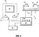
FIG. 4 is a schematic illustration of an exemplary robotic surgical system configured to releasably receive the surgical instrument ofFIG. 1 ; -
FIG. 5 is a front, perspective view of a jaw drive sub-assembly of the surgical instrument ofFIG. 1 ; -
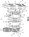
FIG. 6 is a rear, perspective view of the jaw drive sub-assembly of the surgical instrument ofFIG. 1 ; -
FIG. 7 is an exploded, perspective view of the jaw drive sub-assembly of the surgical instrument ofFIG. 1 ; -
FIG. 8 is an enlarged, front perspective view of the area of detail "8" inFIG. 7 ; -
FIG. 9 is an enlarged, rear perspective view of the area of detail "8" inFIG. 7 ; -
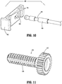
FIG. 10 is an exploded, perspective view illustrating a drive rod and lock plate of the jaw drive sub-assembly of the surgical instrument ofFIG. 1 ; -
FIG. 11 is an enlarged, perspective view of the area of detail "11" inFIG. 7 ; -
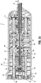
FIG. 12 is a longitudinal, cross-sectional view taken along section line "12-12" ofFIG. 1 ; -
FIG. 13 is a longitudinal, cross-sectional view taken along section line "13-13" ofFIG. 1 ; -
FIG. 14 is a transverse, cross-sectional view taken along section line "14-14" ofFIG. 3 ; -
FIG. 15 is a transverse, cross-sectional view taken along section line "15-15" ofFIG. 3 ; -
FIG. 16 is a transverse, cross-sectional view taken along section line "16-16" ofFIG. 12 ; -
FIG. 17 is a transverse, cross-sectional view taken along section line "17-17" ofFIG. 12 ; -
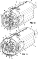
FIG. 18 is a transverse, cross-sectional view taken along section line "18-18" ofFIG. 12 ; -
FIG. 19 is a transverse, cross-sectional view taken along section line "19-19" ofFIG. 12 ; -
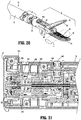
FIG. 20 is a perspective view of a distal potion of the surgical instrument ofFIG. 1 with the end effector assembly disposed in an open position; -
FIG. 21 is a longitudinal, cross-sectional view of another proximal portion of the surgical instrument ofFIG. 1 illustrating the jaw drive sub-assembly transitioning the end effector assembly from the open position towards a closed position; -
FIG. 22 is a perspective view of the distal potion of the surgical instrument ofFIG. 1 with the end effector assembly disposed in the closed position; and -
FIG. 23 is a longitudinal, cross-sectional view of the proximal portion of the surgical instrument ofFIG. 21 illustrating the jaw drive sub-assembly with the end effector assembly in the closed position. - Referring to
FIGS. 1-3 , asurgical instrument 10 provided in accordance with the present disclosure generally includes ahousing 20, ashaft 30 extending distally fromhousing 20, and endeffector assembly 40 extending distally fromshaft 30, and agearbox assembly 100 disposed withinhousing 20 and operably associated withend effector assembly 40.Instrument 10 is detailed herein as an articulating electrosurgical forceps configured for use with a robotic surgical system, e.g., robotic surgical system 1000 (FIG. 4 ). However, the aspects and features ofinstrument 10 provided in accordance with the present disclosure, detailed below, are equally applicable for use with other suitable surgical instruments and/or in other suitable surgical systems. - With particular reference to
FIG. 1 ,housing 20 ofinstrument 10 includes first andsecond body portion proximal face plate 24 that cooperate to enclosegearbox assembly 100 therein.Proximal face plate 24 includes apertures defined therein through which inputs 110-140 ofgearbox assembly 100 extend. A pair of latch levers 26 (only one of which is illustrated inFIG. 1 ) extending outwardly from opposing sides ofhousing 20 and enable releasable engagement ofhousing 20 with a robotic arm of a surgical system, e.g., robotic surgical system 1000 (FIG. 4 ). Anaperture 28 defined throughhousing 20 permits thumbwheel 440 to extend therethrough to enable manual manipulation ofthumbwheel 440 from the exterior ofhousing 20 to, as detailed below, permit manual opening and closing ofend effector assembly 40. -
Shaft 30 ofinstrument 10 includes adistal segment 32, aproximal segment 34, and an articulatingsection 36 disposed between the distal andproximal segments section 36 includes one or more articulatingcomponents 37, e.g., links, joints, etc. A plurality ofarticulation cables 38, e.g., four (4) articulation cables, or other suitable actuators, extend through articulatingsection 36. More specifically,articulation cables 38 are operably coupled todistal segment 32 ofshaft 30 at the distal ends thereof and extend proximally fromdistal segment 32 ofshaft 30, through articulatingsection 36 ofshaft 30 andproximal segment 34 ofshaft 30, and intohousing 20, whereinarticulation cables 38 operably couple with anarticulation sub-assembly 200 ofgearbox assembly 100 to enable selective articulation of distal segment 32 (and, thus end effector assembly 40) relative toproximal segment 34 andhousing 20, e.g., about at least two axes of articulation (yaw and pitch articulation, for example).Articulation cables 38 are arranged in a generally rectangular configuration, although other suitable configurations are also contemplated. - With respect to articulation of
end effector assembly 40 relative toproximal segment 34 ofshaft 30, actuation ofarticulation cables 38 is effected in pairs. More specifically, in order to pitchend effector assembly 40, the upper pair ofcables 38 are actuated in a similar manner while the lower pair ofcables 38 are actuated in a similar manner relative to one another but an opposite manner relative to the upper pair ofcables 38. With respect to yaw articulation, the right pair ofcables 38 are actuated in a similar manner while the left pair ofcables 38 are actuated in a similar manner relative to one another but an opposite manner relative to the right pair ofcables 38. - Continuing with reference to
FIG. 1 ,end effector assembly 40 includes first andsecond jaw members jaw member proximal flange portion distal body portion Distal body portions surfaces Proximal flange portions pivot 50 and are operably coupled to one another via a cam-slot assembly 52 including a cam pin slidably received within cam slots defined within theproximal flange portion jaw members jaw member 42 relative tojaw member 44 anddistal segment 32 ofshaft 30 between a spaced-apart position (e.g., an open position of end effector assembly 40) and an approximated position (e.g. a closed position of end effector assembly 40) for grasping tissue "T" (FIGS. 20 and22 ) between tissue-contactingsurfaces jaw members distal segment 32 ofshaft 30. - In embodiments, longitudinally-extending knife channels 49 (only
knife channel 49 ofjaw member 44 is illustrated; the knife channel ofjaw member 42 is similarly configured) are defined through tissue-contactingsurfaces jaw members FIGS. 12-15 ) extending fromhousing 20 throughshaft 30 to endeffector assembly 40 and a knife blade (not shown) disposed withinend effector assembly 40 betweenjaw members FIGS. 20 and22 ) grasped between tissue-contactingsurfaces jaw members FIGS. 12-15 ) is operably coupled to a knife drive sub-assembly 300 of gearbox assembly 100 (FIGS. 2A-2B ) at a proximal end thereof to enable selective actuation thereof to, in turn, reciprocate the knife blade (not shown) betweenjaw members FIGS. 20 and22 ) grasped between tissue-contactingsurfaces - Referring still to
FIG. 1 , adrive rod 484 is operably coupled to cam-slot assembly 52 ofend effector assembly 40, e.g., engaged with the cam pin thereof, such that longitudinal actuation ofdrive rod 484 pivotsjaw member 42 relative tojaw member 44 between the spaced-apart and approximated positions. More specifically, urgingdrive rod 484 proximally pivotsjaw member 42 relative tojaw member 44 towards the approximated position while urgingdrive rod 484 distally pivotsjaw member 42 relative tojaw member 44 towards the spaced-apart position. However, other suitable mechanisms and/or configurations for pivotingjaw member 42 relative tojaw member 44 between the spaced-apart and approximated positions in response to selective actuation ofdrive rod 484 are also contemplated. Driverod 484 extends proximally fromend effector assembly 40 throughshaft 30 and intohousing 20 whereindrive rod 484 is operably coupled with ajaw drive sub-assembly 400 of gearbox assembly 100 (FIGS. 2A-2B ) to enable selective actuation ofend effector assembly 40 to grasp tissue "T" (FIGS. 20 and22 ) therebetween and apply a closure force within an appropriate jaw closure force range, as detailed below. - Tissue-contacting
surfaces jaw members FIGS. 20 and22 ) grasped therebetween, although tissue-contactingsurfaces FIGS. 20 and22 ) grasped therebetween for energy-based tissue treatment.Instrument 10 defines a conductive pathway (not shown) throughhousing 20 andshaft 30 to endeffector assembly 40 that may include lead wires, contacts, and/or electrically-conductive components to enable electrical connection of tissue-contactingsurfaces jaw members surfaces FIGS. 20 and22 ) grasped between tissue-contactingsurfaces - With additional reference to
FIGS. 2A ,2B , and3 , as noted above,gearbox assembly 100 is disposed withinhousing 20 and includes anarticulation sub-assembly 200, aknife drive sub-assembly 300, and ajaw drive sub-assembly 400.Articulation sub-assembly 200 is operably coupled between first andsecond inputs gearbox assembly 100 and articulation cables 38 (FIG. 1 ) such that, upon receipt of appropriate inputs into first and/orsecond inputs articulation sub-assembly 200 manipulates cables 38 (FIG. 1 ) to articulateend effector assembly 40 in a desired direction, e.g., to pitch and/or yawend effector assembly 40. -
Knife drive sub-assembly 300 is operably coupled betweenthird input 130 ofgearbox assembly 100 and knife tube 62 (FIGS. 12-15 ) such that, upon receipt of appropriate input intothird input 130,knife drive sub-assembly 300 manipulates knife tube 62 (FIGS. 12-15 ) to reciprocate the knife blade (not shown) betweenjaw members FIGS. 20 and22 ) grasped between tissue-contactingsurfaces - Jaw drive sub-assembly 400, as detailed below, is operably coupled between
fourth input 140 ofgearbox assembly 100 and driverod 484 such that, upon receipt of appropriate input intofourth input 140,jaw drive sub-assembly 400 pivotsjaw members FIGS. 20 and22 ) therebetween and apply a closure force within an appropriate closure force range. -
Gearbox assembly 100 is configured to operably interface with a robotic surgical system 1000 (FIG. 4 ) wheninstrument 10 is mounted on robotic surgical system 1000 (FIG. 4 ), to enable robotic operation ofgearbox assembly 100 to provide the above-detailed functionality. That is, robotic surgical system 1000 (FIG. 4 ) selectively provides inputs to inputs 110-140 ofgearbox assembly 100 to articulateend effector assembly 40, grasp tissue "T" (FIGS. 20 and22 ) betweenjaw members FIGS. 20 and22 ) grasped betweenjaw members gearbox assembly 100 be configured to interface with any other suitable surgical system, e.g., a manual surgical handle, a powered surgical handle, etc. For the purposes herein, robotic surgical system 1000 (FIG. 4 ) is generally described. - Turning to
FIG. 4 , roboticsurgical system 1000 is configured for use in accordance with the present disclosure. Aspects and features of roboticsurgical system 1000 not germane to the understanding of the present disclosure are omitted to avoid obscuring the aspects and features of the present disclosure in unnecessary detail. - Robotic
surgical system 1000 generally includes a plurality ofrobot arms control device 1004; and anoperating console 1005 coupled withcontrol device 1004.Operating console 1005 may include adisplay device 1006, which may be set up in particular to display three-dimensional images; andmanual input devices robot arms surgical system 1000 may be configured for use on apatient 1013 lying on a patient table 1012 to be treated in a minimally invasive manner. Roboticsurgical system 1000 may further include adatabase 1014, in particular coupled to controldevice 1004, in which are stored, for example, pre-operative data frompatient 1013 and/or anatomical atlases. - Each of the
robot arms FIG. 1 ), thus providing such functionality on a roboticsurgical system 1000. -
Robot arms device 1004.Control device 1004, e.g., a computer, may be configured to activate the motors, in particular by means of a computer program, in such a way thatrobot arms manual input devices Control device 1004 may also be configured in such a way that it regulates the movement ofrobot arms - With reference to
FIG. 5-7 and12-19 , jaw drive sub-assembly 400 ofgearbox assembly 100 is shown generally including aninput shaft 410, aninput gear 420, adrive gear 430, athumbwheel 440, aspring force assembly 450, and adrive rod assembly 480. -
Input shaft 410 includes aproximal end portion 412 operably coupled tofourth input 140 and adistal end portion 414 havinginput gear 420 engaged thereon such that rotational input provided tofourth input 140 drives rotation ofinput shaft 410 to, thereby, drive rotation ofinput gear 420.Input gear 420 is disposed in meshed engagement withround gear 432 ofdrive gear 430 such that rotation ofinput gear 420, e.g., in response to a rotational input provided atfourth input 140, effects rotation ofdrive gear 430 in an opposite direction (seeFIG. 16 ).Thumbwheel 440 is also disposed in meshed engagement withround gear 432 ofdrive gear 430 such that rotation ofthumbwheel 440 effects rotation ofdrive gear 430 in an opposite direction, thus enabling manual driving ofdrive gear 430 via manipulation of thumbwheel 440 (seeFIG. 16 ). - Also referring to
FIG. 11 ,drive gear 430, as noted above, includes around gear 432.Drive gear 430 further includes alead screw 434 fixedly engaged, e.g., monolithically formed, withround gear 432 such that rotation ofround gear 432 effects similar rotation oflead screw 434. - With additional reference to
FIGS. 8 and 9 ,spring force assembly 450 includes aproximal hub 452, adistal hub 454, acompression spring 456, and aspring washer 458.Spring force assembly 450 further includes a pair of guide bars 470. - Proximal and
distal hubs spring force assembly 450 may be identical components that are oriented, positioned, and/or coupled to other components differently, thus providing different functionality while reducing the number of different parts required to be manufactured. The features of proximal anddistal hubs distal hub distal hub distal hubs - Proximal and
distal hubs spring force assembly 450 each include abody 461 defining acavity 462 and aretainer guide 463 extending radially outwardly from opposed sides ofbody 461. Eachretainer guide 463 defines atrough 464 and includes ashoulder 465 extending into therespective trough 464. Proximal anddistal hubs cavities 462 face one another and such that theshoulder 465 of each pair of retainer guides 463 of proximal anddistal hubs -
Proximal hub 452 further includes atransverse slot 466 defined therethrough that is configured to receivelock plate 482 ofdrive rod assembly 480, as detailed below, to fixlock plate 482 and, thus, a proximal end portion ofdrive rod 484 relative to proximal hub 452 (seeFIGS. 18 and 19 ). Once engaged in this manner,drive rod 484 is locked in position coaxially disposed throughproximal hub 452,distal hub 454,compression spring 456, and drivegear 430. -
Distal hub 454 defines a threadedcentral bore 468 throughbody 461 thereof. Threadedcentral bore 468 receiveslead screw 434 ofdrive gear 430 therethrough in threaded engagement therewith such that rotation oflead screw 434 drives translation ofdistal hub 454 longitudinally alonglead screw 434. -
Compression spring 456 is disposed between proximal anddistal hubs cavity 461 ofproximal hub 452 and a distal portion thereof disposed withincavity 461 ofdistal hub 462. At least a portion ofcompression spring 456 is disposed about and/or configured to receive a portion oflead screw 434 ofdrive gear 430 therethrough.Spring washer 458 is positioned withincavity 461 ofproximal hub 452 betweenproximal hub 452 andcompression spring 456, although other configurations are also contemplated. - Each
guide bar 470 is slidably received within thetroughs 464 of a corresponding pair of retainer guides 463 of proximal anddistal hubs guide bar 470 includes a pair of spaced-apartrims shoulders 465 of the respective retainer guides 463, thereby defining a maximum distance between proximal anddistal hubs distal hubs - Referring to
FIGS. 10 and19 , in conjunction withFIGS. 5-7 , driverod assembly 480 includeslock plate 482 and driverod 484.Lock plate 482 defines acentral keyhole 485 and a pair ofslots 486, e.g., arcuate slots, defined on a distal face oflock plate 482 on either side ofcentral keyhole 485.Lock plate 482 is configured for insertion throughtransverse slot 466 ofproximal hub 452 and, once installed therein, portions ofspring washer 458 are configured for receipt withinslots 486 to securelock plate 482 in engagement withinproximal hub 452.Spring washer 458 is maintained in position withinslots 486 under the bias ofcompression spring 456 which, at the maximum distance between proximal anddistal hubs 452, 454 (as set byrims shoulders 465 of retainer guides 463), is pre-compressed. - Drive
rod 484, as noted above, includes a distal end portion operably coupled to cam-slot assembly 52 of end effector assembly 40 (FIG. 1 ). Driverod 484 extends proximally throughshaft 30,housing 20, and gearbox assembly 100 (seeFIGS. 1-3 ) and is engaged withinlock plate 482 at a proximal end portion ofdrive rod 484. More specifically,drive rod 484 defines awaist 488 towards the proximal end thereof that is configured to lock in engagement withincentral keyhole 485 oflock plate 482, e.g., via longitudinal translation ofdrive rod 484 intocentral keyhole 485 untilwaist 488 is aligned withcentral keyhole 485, followed by transverse movement ofdrive rod 484 relative to lockplate 482, to thereby fix the proximal end portion ofdrive rod 484 relative to lockplate 482 and, thus, relative toproximal hub 452 due to the engagement oflock plate 482 withinproximal hub 452. - Turning to
FIGS. 3 ,12-15 , and17 ,knife drive sub-assembly 300 includes aninput shaft 310, aninput gear 320, acentral gear 330 defining external threading and internal threading, and alead screw 340.Input shaft 310 extends parallel and offset relative to inputshaft 410 and includes aproximal end portion 312 operably coupled tothird input 130 of gearbox assembly 100 (FIGS. 2A and2B ) and adistal end portion 314 havinginput gear 320 engaged thereon such that rotational input provided tothird input 130 drives rotation ofinput shaft 310 to, thereby, drive rotation ofinput gear 320.Input gear 320 is disposed in meshed engagement with the external threading ofcentral gear 330.Central gear 330 is coaxial with and positioned distally ofdrive gear 430. -
Lead screw 340 extends throughcentral gear 330 and is threadingly engaged with the internal threading thereof such that rotation ofcentral gear 330, e.g., in response to a rotational input provide tothird input 130, translateslead screw 340.Lead screw 340 is fixedly engaged about a proximal end portion ofknife tube 62 such that translation oflead screw 340 translatesknife tube 62, e.g., to thereby translate the knife blade (not shown) betweenjaw members 42, 44 (FIG. 1 ).Lead screw 340 andknife tube 62 are coaxially disposed aboutdrive rod 484. - Referring to
FIGS. 5-7 and20-23 , in use,jaw members FIG. 20 ) and, correspondingly, proximal anddistal hubs such drive rod 484 is disposed in a distal-most position (seeFIGS. 12-15 ). Further, in this position,compression spring 456 is disposed in a least-compressed condition; although, as noted above, even in the least-compressed condition,compression spring 456 is partially compressed due to the retention ofcompression spring 456 in a pre-compressed configuration between proximal anddistal hubs - In response to an input to close
end effector assembly 40, e.g., rotational input tofourth input 140 or a manual input torotation wheel 440,drive shaft 410 is rotated to thereby rotateinput gear 420 which, in turn, rotatesdrive gear 430 such thatdistal hub 454 is translated proximally towards proximal hub 452 (seeFIG. 21 ). With reference toFIG. 21 , proximal translation ofdistal hub 454 urgesdistal hub 454 againstcompression spring 456. Initially, where forces resisting approximation ofjaw members compression spring 456, the closure force applied byjaw members distal hub 454 proximally againstcompression spring 456 urgescompression spring 456 proximally which, in turn, urgeslock plate 482 and, thus, driverod 484 proximally to pivotjaw member 42 relative tojaw member 44 from the spaced-apart position towards the approximated position to grasp tissue "T" therebetween (FIGS. 20 and22 ). - Referring to
FIGS. 5-7 ,22, and 23 , upon further approximation ofjaw members jaw members jaw members jaw members jaw members fourth input 140. More specifically, and with reference toFIG. 23 , once the threshold has been reached, further rotational input tofourth input 140 rotates driveshaft 410,input gear 420, and drivegear 430 to translatedistal hub 454 further proximally intocompression spring 456. However, rather thancompression spring 456 urgingproximal hub 452 further proximally to continue approximation ofjaw members compression spring 456 is compressed, enablingproximal hub 452 and, thus, driverod 484 to remain in position, thus inhibiting application of additional closure force betweenjaw members - Referring to
FIG. 22 , with tissue "T" grasped betweenjaw members jaw members jaw members FIGS. 14 and17 , in order to advance the knife blade (not shown), a rotational input is provided to input 130 to drive rotation ofinput shaft 310,input gear 320, andcentral gear 330, thereby translatinglead screw 340 distally such thatknife tube 62 is likewise translated distally to advance the knife blade (not shown) betweenjaw members - Once tissue "T" is cut, an opposite rotation input is provided to input 130 to return the knife blade (not shown) to its initial position proximally of
body portions jaw members 42, 44 (seeFIG. 1 ). Thereafter, an opposite input is provided to input 140 (or rotation wheel 440) to returnjaw members - It will be understood that various modifications may be made to the embodiments disclosed herein. Therefore, the above description should not be construed as limiting, but merely as exemplifications of various embodiments. Those skilled in the art will envision other modifications within the scope and spirit of the claims appended thereto.
- The invention may be described by reference to the following numbered paragraphs: -
- 1. A gearbox assembly for a surgical instrument, comprising:
- a drive gear including a round gear configured to receive a rotational input and a lead screw coupled to the round gear such that the rotational input to the round gear rotates the lead screw;
- a first hub threadingly engaged about the lead screw such that rotation of the lead screw translates the first hub therealong;
- a second hub spaced-apart from the first hub;
- a drive rod engaged with the second hub; and
- a compression spring disposed between the first and second hubs,
- wherein, when a force acting against translation of the drive rod is below a threshold, the rotational input translates the first hub to, in turn, translate the compression spring to, in turn, translate the second hub and the drive rod, and
- wherein, when the force acting against translation of the drive rod is equal to or above the threshold, the rotational input translates the first hub to, in turn, compress the compression spring against the second hub while the second hub and drive rod are maintained in position.
- 2. The gearbox assembly according to
paragraph 1, further comprising an input gear disposed in meshed engagement with the round gear of the drive gear to provide the rotational input to the round gear. - 3. The gearbox assembly according to
paragraph 2, further comprising an external input and an input shaft operably coupled between the external input and the input gear such that rotational driving of the external input provides the rotational input to the round gear. - 4. The gearbox assembly according to
paragraph 3, wherein the first hub is a distal hub and the second hub is a proximal hub, the external input disposed proximally of the proximal hub and the input gear disposed distally of the distal hub. - 5. The gearbox assembly according to
paragraph 1, wherein the drive rod extends coaxially through at least one of: the first hub, the second hub, the compression spring, or the drive gear. - 6. The gearbox assembly according to
paragraph 1, wherein the drive rod extends coaxially through each of: the first hub, the second hub, the compression spring, and the drive gear. - 7. The gearbox assembly according to
paragraph 1, wherein the first and second hubs are coupled to one another to define a maximum distance therebetween and wherein the compression spring is partially compressed when the first and second hubs define the maximum distance therebetween. - 8. The gearbox assembly according to paragraph 7, further comprising at least one guide bar operably coupled between the first and second hubs, the at least one guide bar defining first and second rims configured to interact with first and second shoulders of the first and second hubs, respectively, to define the maximum distance between the first and second hubs.
- 9. The gearbox assembly according to paragraph 7, wherein the first hub is moved towards the second hub when the compression spring is compressed against the second hub to reduce a distance between the first and second hubs.
- 10. The gearbox assembly according to
paragraph 1, wherein the drive rod is engaged with the second hub via a lock plate defining a keyhole. - 11. A surgical instrument, comprising:
- a housing;
- a shaft extending distally from the housing;
- an end effector assembly extending distally from the shaft, the end effector assembly including first and second jaw members, at least the first jaw member movable relative to the second jaw member from a spaced-apart position to an approximated position to grasp tissue therebetween; and
- a gearbox assembly disposed within the housing, the gearbox assembly including:
- a drive gear including a round gear configured to receive a rotational input and a lead screw coupled to the round gear such that the rotational input to the round gear rotates the lead screw;
- a first hub threadingly engaged about the lead screw such that rotation of the lead screw translates the first hub therealong;
- a second hub spaced-apart from the first hub;
- a drive rod engaged with the second hub at a proximal end portion thereof and operably coupled to the end effector assembly at a distal end portion thereof such that translation of the drive rod moves at least the first jaw member from the spaced-apart position towards the approximated position; and
- a compression spring disposed between the first and second hubs,
- wherein, when a force acting against movement of at least the first jaw member towards the approximated position is below a threshold, the rotational input translates the first hub to, in turn, translate the compression spring to, in turn, translate the second hub and the drive rod to move at least the first jaw member towards the approximated position, and
- wherein, when the force acting against movement of at least the first jaw member towards the approximated position is equal to or above the threshold, the rotational input translates the first hub to, in turn, compress the compression spring against the second hub while the second hub, the drive rod, and at least the first jaw member are maintained in position.
- 12. The surgical instrument according to
paragraph 11, wherein the gearbox assembly further comprises an input gear disposed in meshed engagement with the round gear of the drive gear to provide the rotational input to the round gear. - 13. The surgical instrument according to
paragraph 12, , wherein the gearbox assembly further comprises an external input and an input shaft operably coupled between the external input and the input gear such that rotational driving of the external input provides the rotational input to the round gear. - 14. The surgical instrument according to
paragraph 13, wherein the first hub is a distal hub and the second hub is a proximal hub, the external input disposed proximally of the proximal hub and the input gear disposed distally of the distal hub. - 15. The surgical instrument according to
paragraph 11, wherein the drive rod extends coaxially through at least one of: the first hub, the second hub, the compression spring, or the drive gear. - 16. The surgical instrument according to
paragraph 11, wherein the drive rod extends coaxially through each of: the first hub, the second hub, the compression spring, and the drive gear. - 17. The surgical instrument according to
paragraph 11, wherein the first and second hubs are coupled to one another to define a maximum distance therebetween and wherein the compression spring is partially compressed when the first and second hubs define the maximum distance therebetween. - 18. The surgical instrument according to
paragraph 17, , wherein the gearbox assembly further comprises at least one guide bar operably coupled between the first and second hubs, the at least one guide bar defining first and second rims configured to interact with first and second shoulders of the first and second hubs, respectively, to define the maximum distance between the first and second hubs. - 19. The surgical instrument according to
paragraph 17, wherein the first hub is moved towards the second hub when the compression spring is compressed against the second hub to reduce a distance between the first and second hubs. - 20. The surgical instrument according to
paragraph 11, wherein the drive rod is engaged with the second hub via a lock plate defining a keyhole.
Claims (15)
- A surgical instrument, comprising:
a gearbox assembly, including:a drive gear including a round gear configured to receive a rotational input and a lead screw coupled to the round gear such that the rotational input to the round gear rotates the lead screw;a first hub threadingly engaged about the lead screw such that rotation of the lead screw translates the first hub therealong;a second hub spaced-apart from the first hub;a drive rod engaged with the second hub; anda compression spring disposed between the first and second hubs, wherein, when a force acting against translation of the drive rod is below a threshold, the rotational input translates the first hub to, in turn, translate the compression spring to, in turn, translate the second hub and the drive rod, andwherein, when the force acting against translation of the drive rod is equal to or above the threshold, the rotational input translates the first hub to, in turn, compress the compression spring against the second hub while the second hub and drive rod are maintained in position. - The surgical instrument according to claim 1, wherein the gearbox assembly further includes an input gear disposed in meshed engagement with the round gear of the drive gear to provide the rotational input to the round gear.
- The surgical instrument according to claim 2, wherein the gearbox assembly further includes an external input and an input shaft operably coupled between the external input and the input gear such that rotational driving of the external input provides the rotational input to the round gear.
- The surgical instrument according to claim 3, wherein the first hub is a distal hub and the second hub is a proximal hub, the external input disposed proximally of the proximal hub and the input gear disposed distally of the distal hub.
- The surgical instrument according to any preceding claim, wherein the drive rod extends coaxially through at least one of: the first hub, the second hub, the compression spring, or the drive gear.
- The surgical instrument according to any preceding claim, wherein the drive rod extends coaxially through each of: the first hub, the second hub, the compression spring, and the drive gear.
- The surgical instrument according to any preceding claim, wherein the first and second hubs are coupled to one another to define a maximum distance therebetween and wherein the compression spring is partially compressed when the first and second hubs define the maximum distance therebetween.
- The surgical instrument according to claim 7, wherein the gearbox assembly further includes at least one guide bar operably coupled between the first and second hubs, the at least one guide bar defining first and second rims configured to interact with first and second shoulders of the first and second hubs, respectively, to define the maximum distance between the first and second hubs.
- The surgical instrument according to claim 7, wherein the first hub is moved towards the second hub when the compression spring is compressed against the second hub to reduce a distance between the first and second hubs.
- The surgical instrument according to any preceding claim, wherein the drive rod is engaged with the second hub via a lock plate defining a keyhole.
- The surgical instrument according to any preceding claim, further comprising:a housing;a shaft extending distally from the housing; andan end effector assembly extending distally from the shaft, the end effector assembly including first and second jaw members, at least the first jaw member movable relative to the second jaw member from a spaced-apart position to an approximated position to grasp tissue therebetween,wherein the gearbox assembly is disposed within the housing.
- The surgical instrument according to claim 11, wherein translation of the drive rod moves at least the first jaw member from the spaced-apart position towards the approximated position.
- The surgical instrument according to claim 11, wherein, when the force is below the threshold, the rotational input causes the drive rod to move the at least the first jaw member towards the approximated position.
- The surgical instrument according to claim 11, wherein, when the force is equal to or above the threshold, the rotational input causes the compression spring to compress against the second hub while the drive rod and the at least the first jaw member are maintained in position.
- The surgical instrument according to any preceding claim, wherein the gearbox assembly is adapted to operably connect to a robotic surgical arm.
Applications Claiming Priority (1)
| Application Number | Priority Date | Filing Date | Title |
|---|---|---|---|
| US16/260,477 US11717355B2 (en) | 2019-01-29 | 2019-01-29 | Drive mechanisms for surgical instruments such as for use in robotic surgical systems |
Publications (2)
| Publication Number | Publication Date |
|---|---|
| EP3689282A1 true EP3689282A1 (en) | 2020-08-05 |
| EP3689282B1 EP3689282B1 (en) | 2024-05-08 |
Family
ID=69374190
Family Applications (1)
| Application Number | Title | Priority Date | Filing Date |
|---|---|---|---|
| EP20154025.9A Active EP3689282B1 (en) | 2019-01-29 | 2020-01-28 | Drive mechanisms for surgical instruments for use in robotic surgical systems |
Country Status (4)
| Country | Link |
|---|---|
| US (3) | US11717355B2 (en) |
| EP (1) | EP3689282B1 (en) |
| JP (1) | JP2020121112A (en) |
| CN (1) | CN111481295B (en) |
Cited By (5)
| Publication number | Priority date | Publication date | Assignee | Title |
|---|---|---|---|---|
| EP3858276A1 (en) * | 2020-01-22 | 2021-08-04 | Covidien LP | Drive and articulation mechanisms for surgical instruments for use in robotic surgical systems |
| EP3949890A1 (en) * | 2020-08-07 | 2022-02-09 | Covidien LP | Manual end effector activation for robotic surgical systems |
| WO2022039933A1 (en) * | 2020-08-20 | 2022-02-24 | Covidien Lp | End effector assembly for use in a robotic surgical instrument |
| WO2022055685A1 (en) * | 2020-09-10 | 2022-03-17 | Covidien Lp | End effector assemblies for surgical instruments such as for use in robotic surgical systems |
| WO2022235625A1 (en) * | 2021-05-03 | 2022-11-10 | Covidien Lp | Motor position control and methods for robotic assisted sealing instrument |
Families Citing this family (22)
| Publication number | Priority date | Publication date | Assignee | Title |
|---|---|---|---|---|
| US10779900B2 (en) * | 2015-12-29 | 2020-09-22 | Covidien Lp | Robotic surgical systems and instrument drive assemblies |
| US10945797B2 (en) * | 2019-01-29 | 2021-03-16 | Covidien Lp | Geared actuation mechanisms for surgical instruments such as for use in robotic surgical systems |
| US11717355B2 (en) | 2019-01-29 | 2023-08-08 | Covidien Lp | Drive mechanisms for surgical instruments such as for use in robotic surgical systems |
| US12059219B2 (en) | 2019-11-15 | 2024-08-13 | Siemens Healthineers Ag | Assisted steering of intracardiac echocardiogram catheters |
| US12029497B2 (en) * | 2019-11-15 | 2024-07-09 | Siemens Healthineers Ag | Interlocking gear system for sterile robotic catheter navigation systems |
| JP7387548B2 (en) * | 2020-07-15 | 2023-11-28 | 株式会社三共 | gaming machine |
| JP7557303B2 (en) * | 2020-08-05 | 2024-09-27 | 株式会社三共 | Gaming Machines |
| US11896333B2 (en) * | 2020-08-19 | 2024-02-13 | Covidien Lp | Robotic surgical instrument |
| US12446983B2 (en) | 2020-09-08 | 2025-10-21 | Covidien Lp | Articulation mechanisms for surgical instruments such as for use in robotic surgical systems |
| US12161386B2 (en) * | 2020-09-11 | 2024-12-10 | Covidien Lp | Surgical instruments having an articulating section such as for use in robotic surgical systems |
| US11925406B2 (en) | 2020-09-14 | 2024-03-12 | Covidien Lp | End effector assemblies for surgical instruments |
| US11957422B2 (en) | 2020-10-15 | 2024-04-16 | Covidien Lp | Surgical instruments for use in robotic surgical systems and methods relating to the same |
| WO2022164683A1 (en) * | 2021-01-29 | 2022-08-04 | Covidien Lp | Surgical instruments for use in robotic surgical systems and methods relating to the same |
| CN113017828B (en) * | 2021-03-01 | 2023-03-14 | 锐志微创医疗科技(常州)有限公司 | A terminal mechanism of a surgical robot |
| US12611246B2 (en) * | 2021-08-16 | 2026-04-28 | Covidien Lp | End effector drive mechanisms for surgical instruments such as for use in robotic surgical systems |
| WO2023031742A1 (en) * | 2021-08-30 | 2023-03-09 | Covidien Lp | Articulation drive assemblies for surgical instruments such as for use in surgical robotic systems |
| CN119997891A (en) * | 2022-09-30 | 2025-05-13 | 柯惠有限合伙公司 | Spring Assisted Sealing Devices |
| CN120569172A (en) | 2023-01-25 | 2025-08-29 | 柯惠Lp公司 | Surgical robotic system and method for calibrating jaw instrument |
| WO2024252260A1 (en) | 2023-06-08 | 2024-12-12 | Covidien Lp | Surgical robotic system and method for velocity-based force feedback in handle controller |
| WO2025083541A1 (en) | 2023-10-17 | 2025-04-24 | Covidien Lp | Surgical stapler including rotating segmented spine members for use with robotic surgical systems |
| WO2025088591A1 (en) | 2023-10-26 | 2025-05-01 | Covidien Lp | Surgical robotic system and method for controlled tissue sealing |
| CN119344862B (en) * | 2024-10-30 | 2025-10-10 | 吉林省金博弘智能科技有限责任公司 | A self-locking instrument forceps capable of multi-angle movement |
Citations (4)
| Publication number | Priority date | Publication date | Assignee | Title |
|---|---|---|---|---|
| WO2017053698A1 (en) * | 2015-09-25 | 2017-03-30 | Covidien Lp | Robotic surgical assemblies and electromechanical instruments thereof |
| US20170367775A1 (en) * | 2009-11-13 | 2017-12-28 | Intuitive Surgical Operations, Inc. | Motor Interface For Parallel Drive Shafts Within an Independently Rotating Member |
| US20180008338A1 (en) * | 2015-02-16 | 2018-01-11 | Covidien Lp | Robotic surgical assemblies and electrosurgical instruments thereof |
| US20180049763A1 (en) * | 2016-08-18 | 2018-02-22 | Covidien Lp | Surgical forceps |
Family Cites Families (205)
| Publication number | Priority date | Publication date | Assignee | Title |
|---|---|---|---|---|
| US5409453A (en) | 1992-08-12 | 1995-04-25 | Vidamed, Inc. | Steerable medical probe with stylets |
| US5762458A (en) | 1996-02-20 | 1998-06-09 | Computer Motion, Inc. | Method and apparatus for performing minimally invasive cardiac procedures |
| US5752973A (en) | 1994-10-18 | 1998-05-19 | Archimedes Surgical, Inc. | Endoscopic surgical gripping instrument with universal joint jaw coupler |
| US5855583A (en) | 1996-02-20 | 1999-01-05 | Computer Motion, Inc. | Method and apparatus for performing minimally invasive cardiac procedures |
| US5792135A (en) | 1996-05-20 | 1998-08-11 | Intuitive Surgical, Inc. | Articulated surgical instrument for performing minimally invasive surgery with enhanced dexterity and sensitivity |
| US6364888B1 (en) | 1996-09-09 | 2002-04-02 | Intuitive Surgical, Inc. | Alignment of master and slave in a minimally invasive surgical apparatus |
| US8529582B2 (en) | 1996-12-12 | 2013-09-10 | Intuitive Surgical Operations, Inc. | Instrument interface of a robotic surgical system |
| US6132368A (en) | 1996-12-12 | 2000-10-17 | Intuitive Surgical, Inc. | Multi-component telepresence system and method |
| US7666191B2 (en) | 1996-12-12 | 2010-02-23 | Intuitive Surgical, Inc. | Robotic surgical system with sterile surgical adaptor |
| US6331181B1 (en) | 1998-12-08 | 2001-12-18 | Intuitive Surgical, Inc. | Surgical robotic tools, data architecture, and use |
| US7699855B2 (en) | 1996-12-12 | 2010-04-20 | Intuitive Surgical Operations, Inc. | Sterile surgical adaptor |
| US8182469B2 (en) | 1997-11-21 | 2012-05-22 | Intuitive Surgical Operations, Inc. | Surgical accessory clamp and method |
| US8206406B2 (en) | 1996-12-12 | 2012-06-26 | Intuitive Surgical Operations, Inc. | Disposable sterile surgical adaptor |
| US7727244B2 (en) | 1997-11-21 | 2010-06-01 | Intuitive Surgical Operation, Inc. | Sterile surgical drape |
| US6714839B2 (en) | 1998-12-08 | 2004-03-30 | Intuitive Surgical, Inc. | Master having redundant degrees of freedom |
| US7758569B2 (en) | 1998-02-24 | 2010-07-20 | Hansen Medical, Inc. | Interchangeable surgical instrument |
| DE69940850D1 (en) | 1998-08-04 | 2009-06-18 | Intuitive Surgical Inc | Articular device for positioning a manipulator for robotic surgery |
| US6659939B2 (en) | 1998-11-20 | 2003-12-09 | Intuitive Surgical, Inc. | Cooperative minimally invasive telesurgical system |
| US8600551B2 (en) | 1998-11-20 | 2013-12-03 | Intuitive Surgical Operations, Inc. | Medical robotic system with operatively couplable simulator unit for surgeon training |
| US6459926B1 (en) | 1998-11-20 | 2002-10-01 | Intuitive Surgical, Inc. | Repositioning and reorientation of master/slave relationship in minimally invasive telesurgery |
| US6951535B2 (en) | 2002-01-16 | 2005-10-04 | Intuitive Surgical, Inc. | Tele-medicine system that transmits an entire state of a subsystem |
| US6493608B1 (en) | 1999-04-07 | 2002-12-10 | Intuitive Surgical, Inc. | Aspects of a control system of a minimally invasive surgical apparatus |
| US7125403B2 (en) | 1998-12-08 | 2006-10-24 | Intuitive Surgical | In vivo accessories for minimally invasive robotic surgery |
| US6770081B1 (en) | 2000-01-07 | 2004-08-03 | Intuitive Surgical, Inc. | In vivo accessories for minimally invasive robotic surgery and methods |
| US6799065B1 (en) | 1998-12-08 | 2004-09-28 | Intuitive Surgical, Inc. | Image shifting apparatus and method for a telerobotic system |
| US6394998B1 (en) | 1999-01-22 | 2002-05-28 | Intuitive Surgical, Inc. | Surgical tools for use in minimally invasive telesurgical applications |
| US6565554B1 (en) | 1999-04-07 | 2003-05-20 | Intuitive Surgical, Inc. | Friction compensation in a minimally invasive surgical apparatus |
| US6594552B1 (en) | 1999-04-07 | 2003-07-15 | Intuitive Surgical, Inc. | Grip strength with tactile feedback for robotic surgery |
| US6424885B1 (en) | 1999-04-07 | 2002-07-23 | Intuitive Surgical, Inc. | Camera referenced control in a minimally invasive surgical apparatus |
| US8944070B2 (en) | 1999-04-07 | 2015-02-03 | Intuitive Surgical Operations, Inc. | Non-force reflecting method for providing tool force information to a user of a telesurgical system |
| JP3504534B2 (en) * | 1999-05-07 | 2004-03-08 | 株式会社マルト長谷川工作所 | Work tools |
| US6716233B1 (en) | 1999-06-02 | 2004-04-06 | Power Medical Interventions, Inc. | Electromechanical driver and remote surgical instrument attachment having computer assisted control capabilities |
| US6315184B1 (en) | 1999-06-02 | 2001-11-13 | Powermed, Inc. | Stapling device for use with an electromechanical driver device for use with anastomosing, stapling, and resecting instruments |
| US6793652B1 (en) | 1999-06-02 | 2004-09-21 | Power Medical Interventions, Inc. | Electro-mechanical surgical device |
| US7695485B2 (en) | 2001-11-30 | 2010-04-13 | Power Medical Interventions, Llc | Surgical device |
| US7594912B2 (en) | 2004-09-30 | 2009-09-29 | Intuitive Surgical, Inc. | Offset remote center manipulator for robotic surgery |
| US9259280B2 (en) | 1999-09-17 | 2016-02-16 | Intuitive Surgical Operations, Inc. | Phantom degrees of freedom in joint estimation and control |
| US10188471B2 (en) | 1999-09-17 | 2019-01-29 | Intuitive Surgical Operations, Inc. | Tele-operative surgical systems and methods of control at joint limits using inverse kinematics |
| US8768516B2 (en) | 2009-06-30 | 2014-07-01 | Intuitive Surgical Operations, Inc. | Control of medical robotic system manipulator about kinematic singularities |
| US8004229B2 (en) | 2005-05-19 | 2011-08-23 | Intuitive Surgical Operations, Inc. | Software center and highly configurable robotic systems for surgery and other uses |
| US6491691B1 (en) | 1999-10-08 | 2002-12-10 | Intuitive Surgical, Inc. | Minimally invasive surgical hook apparatus and method for using same |
| US6206903B1 (en) | 1999-10-08 | 2001-03-27 | Intuitive Surgical, Inc. | Surgical tool with mechanical advantage |
| US6312435B1 (en) | 1999-10-08 | 2001-11-06 | Intuitive Surgical, Inc. | Surgical instrument with extended reach for use in minimally invasive surgery |
| US6645196B1 (en) | 2000-06-16 | 2003-11-11 | Intuitive Surgical, Inc. | Guided tool change |
| US6902560B1 (en) | 2000-07-27 | 2005-06-07 | Intuitive Surgical, Inc. | Roll-pitch-roll surgical tool |
| US6746443B1 (en) | 2000-07-27 | 2004-06-08 | Intuitive Surgical Inc. | Roll-pitch-roll surgical tool |
| US7048744B2 (en) | 2001-04-26 | 2006-05-23 | Sol Wiess | Attachable surgical accessory instrument |
| US6840938B1 (en) | 2000-12-29 | 2005-01-11 | Intuitive Surgical, Inc. | Bipolar cauterizing instrument |
| US6554829B2 (en) | 2001-01-24 | 2003-04-29 | Ethicon, Inc. | Electrosurgical instrument with minimally invasive jaws |
| US6994708B2 (en) | 2001-04-19 | 2006-02-07 | Intuitive Surgical | Robotic tool with monopolar electro-surgical scissors |
| US6783524B2 (en) | 2001-04-19 | 2004-08-31 | Intuitive Surgical, Inc. | Robotic surgical tool with ultrasound cauterizing and cutting instrument |
| US7824401B2 (en) | 2004-10-08 | 2010-11-02 | Intuitive Surgical Operations, Inc. | Robotic tool with wristed monopolar electrosurgical end effectors |
| US7607440B2 (en) | 2001-06-07 | 2009-10-27 | Intuitive Surgical, Inc. | Methods and apparatus for surgical planning |
| EP1408846B1 (en) | 2001-06-29 | 2012-03-07 | Intuitive Surgical Operations, Inc. | Platform link wrist mechanism |
| US6817974B2 (en) | 2001-06-29 | 2004-11-16 | Intuitive Surgical, Inc. | Surgical tool having positively positionable tendon-actuated multi-disk wrist joint |
| US6676684B1 (en) | 2001-09-04 | 2004-01-13 | Intuitive Surgical, Inc. | Roll-pitch-roll-yaw surgical tool |
| US6728599B2 (en) | 2001-09-07 | 2004-04-27 | Computer Motion, Inc. | Modularity system for computer assisted surgery |
| CN100522096C (en) | 2001-12-04 | 2009-08-05 | 能量医学介入公司 | System and method for calibrating a surgical instrument |
| US6839612B2 (en) | 2001-12-07 | 2005-01-04 | Institute Surgical, Inc. | Microwrist system for surgical procedures |
| US6793653B2 (en) | 2001-12-08 | 2004-09-21 | Computer Motion, Inc. | Multifunctional handle for a medical robotic system |
| US6602252B2 (en) | 2002-01-03 | 2003-08-05 | Starion Instruments Corporation | Combined dissecting, cauterizing, and stapling device |
| US6969385B2 (en) | 2002-05-01 | 2005-11-29 | Manuel Ricardo Moreyra | Wrist with decoupled motion transmission |
| EP2901958B1 (en) | 2002-12-06 | 2019-02-06 | Intuitive Surgical Operations, Inc. | Flexible wrist for surgical tool |
| US7386365B2 (en) | 2004-05-04 | 2008-06-10 | Intuitive Surgical, Inc. | Tool grip calibration for robotic surgery |
| US8882657B2 (en) | 2003-03-07 | 2014-11-11 | Intuitive Surgical Operations, Inc. | Instrument having radio frequency identification systems and methods for use |
| US7410483B2 (en) | 2003-05-23 | 2008-08-12 | Novare Surgical Systems, Inc. | Hand-actuated device for remote manipulation of a grasping tool |
| US9002518B2 (en) | 2003-06-30 | 2015-04-07 | Intuitive Surgical Operations, Inc. | Maximum torque driving of robotic surgical tools in robotic surgical systems |
| US7379790B2 (en) | 2004-05-04 | 2008-05-27 | Intuitive Surgical, Inc. | Tool memory-based software upgrades for robotic surgery |
| US7143925B2 (en) | 2004-07-28 | 2006-12-05 | Ethicon Endo-Surgery, Inc. | Surgical instrument incorporating EAP blocking lockout mechanism |
| US7857183B2 (en) | 2004-07-28 | 2010-12-28 | Ethicon Endo-Surgery, Inc. | Surgical instrument incorporating an electrically actuated articulation mechanism |
| WO2006015319A2 (en) | 2004-07-30 | 2006-02-09 | Power Medical Interventions, Inc. | Flexible shaft extender and method of using same |
| US7540872B2 (en) | 2004-09-21 | 2009-06-02 | Covidien Ag | Articulating bipolar electrosurgical instrument |
| US9261172B2 (en) | 2004-09-30 | 2016-02-16 | Intuitive Surgical Operations, Inc. | Multi-ply strap drive trains for surgical robotic arms |
| US9700334B2 (en) | 2004-11-23 | 2017-07-11 | Intuitive Surgical Operations, Inc. | Articulating mechanisms and link systems with torque transmission in remote manipulation of instruments and tools |
| US8465474B2 (en) | 2009-05-19 | 2013-06-18 | Intuitive Surgical Operations, Inc. | Cleaning of a surgical instrument force sensor |
| US8496647B2 (en) | 2007-12-18 | 2013-07-30 | Intuitive Surgical Operations, Inc. | Ribbed force sensor |
| US8108072B2 (en) | 2007-09-30 | 2012-01-31 | Intuitive Surgical Operations, Inc. | Methods and systems for robotic instrument tool tracking with adaptive fusion of kinematics information and image information |
| US8147503B2 (en) | 2007-09-30 | 2012-04-03 | Intuitive Surgical Operations Inc. | Methods of locating and tracking robotic instruments in robotic surgical systems |
| US8398541B2 (en) | 2006-06-06 | 2013-03-19 | Intuitive Surgical Operations, Inc. | Interactive user interfaces for robotic minimally invasive surgical systems |
| US8273076B2 (en) | 2005-06-30 | 2012-09-25 | Intuitive Surgical Operations, Inc. | Indicator for tool state and communication in multi-arm robotic telesurgery |
| CN103192388B (en) | 2005-06-30 | 2016-02-10 | 直观外科手术操作公司 | A kind of robot medical system |
| US8579176B2 (en) | 2005-07-26 | 2013-11-12 | Ethicon Endo-Surgery, Inc. | Surgical stapling and cutting device and method for using the device |
| US8079950B2 (en) | 2005-09-29 | 2011-12-20 | Intuitive Surgical Operations, Inc. | Autofocus and/or autoscaling in telesurgery |
| WO2007075864A1 (en) | 2005-12-20 | 2007-07-05 | Intuitive Surgical, Inc. | Instrument interface of a robotic surgical system |
| US7689320B2 (en) | 2005-12-20 | 2010-03-30 | Intuitive Surgical Operations, Inc. | Robotic surgical system with joint motion controller adapted to reduce instrument tip vibrations |
| WO2007111749A2 (en) | 2005-12-20 | 2007-10-04 | Intuitive Surgical, Inc. | Method for handling an operator command exceeding a medical device state limitation in a medical robotic system |
| US7741802B2 (en) | 2005-12-20 | 2010-06-22 | Intuitive Surgical Operations, Inc. | Medical robotic system with programmably controlled constraints on error dynamics |
| US7453227B2 (en) | 2005-12-20 | 2008-11-18 | Intuitive Surgical, Inc. | Medical robotic system with sliding mode control |
| US8182470B2 (en) | 2005-12-20 | 2012-05-22 | Intuitive Surgical Operations, Inc. | Telescoping insertion axis of a robotic surgical system |
| US7819859B2 (en) | 2005-12-20 | 2010-10-26 | Intuitive Surgical Operations, Inc. | Control system for reducing internally generated frictional and inertial resistance to manual positioning of a surgical manipulator |
| US7762825B2 (en) | 2005-12-20 | 2010-07-27 | Intuitive Surgical Operations, Inc. | Electro-mechanical interfaces to mount robotic surgical arms |
| US8054752B2 (en) | 2005-12-22 | 2011-11-08 | Intuitive Surgical Operations, Inc. | Synchronous data communication |
| US7756036B2 (en) | 2005-12-22 | 2010-07-13 | Intuitive Surgical Operations, Inc. | Synchronous data communication |
| US7757028B2 (en) | 2005-12-22 | 2010-07-13 | Intuitive Surgical Operations, Inc. | Multi-priority messaging |
| US7930065B2 (en) | 2005-12-30 | 2011-04-19 | Intuitive Surgical Operations, Inc. | Robotic surgery system including position sensors using fiber bragg gratings |
| US7907166B2 (en) | 2005-12-30 | 2011-03-15 | Intuitive Surgical Operations, Inc. | Stereo telestration for robotic surgery |
| US8628518B2 (en) | 2005-12-30 | 2014-01-14 | Intuitive Surgical Operations, Inc. | Wireless force sensor on a distal portion of a surgical instrument and method |
| US7835823B2 (en) | 2006-01-05 | 2010-11-16 | Intuitive Surgical Operations, Inc. | Method for tracking and reporting usage events to determine when preventive maintenance is due for a medical robotic system |
| US8597182B2 (en) | 2006-04-28 | 2013-12-03 | Intuitive Surgical Operations, Inc. | Robotic endoscopic retractor for use in minimally invasive surgery |
| CN104688349B (en) | 2006-06-13 | 2017-05-10 | 直观外科手术操作公司 | Minimally invasive surgical system |
| US8597280B2 (en) | 2006-06-13 | 2013-12-03 | Intuitive Surgical Operations, Inc. | Surgical instrument actuator |
| WO2007146984A2 (en) | 2006-06-13 | 2007-12-21 | Intuitive Surgical, Inc. | Control system configured to compensate for non-ideal actuator-to-joint linkage characteristics in a medical robotic system |
| US10008017B2 (en) | 2006-06-29 | 2018-06-26 | Intuitive Surgical Operations, Inc. | Rendering tool information as graphic overlays on displayed images of tools |
| US9718190B2 (en) | 2006-06-29 | 2017-08-01 | Intuitive Surgical Operations, Inc. | Tool position and identification indicator displayed in a boundary area of a computer display screen |
| US20090192523A1 (en) | 2006-06-29 | 2009-07-30 | Intuitive Surgical, Inc. | Synthetic representation of a surgical instrument |
| US8151661B2 (en) | 2006-06-30 | 2012-04-10 | Intuituve Surgical Operations, Inc. | Compact capstan |
| US7391173B2 (en) | 2006-06-30 | 2008-06-24 | Intuitive Surgical, Inc | Mechanically decoupled capstan drive |
| US8029531B2 (en) | 2006-07-11 | 2011-10-04 | Cambridge Endoscopic Devices, Inc. | Surgical instrument |
| EP2083728A4 (en) | 2006-10-05 | 2014-10-08 | Covidien Lp | Flexible endoscopic stitching devices |
| US7736254B2 (en) | 2006-10-12 | 2010-06-15 | Intuitive Surgical Operations, Inc. | Compact cable tension tender device |
| US7935130B2 (en) | 2006-11-16 | 2011-05-03 | Intuitive Surgical Operations, Inc. | Two-piece end-effectors for robotic surgical tools |
| US8758229B2 (en) | 2006-12-21 | 2014-06-24 | Intuitive Surgical Operations, Inc. | Axial visualization systems |
| US9301807B2 (en) | 2007-06-13 | 2016-04-05 | Intuitive Surgical Operations, Inc. | Surgical system counterbalance |
| US8620473B2 (en) | 2007-06-13 | 2013-12-31 | Intuitive Surgical Operations, Inc. | Medical robotic system with coupled control modes |
| US9138129B2 (en) | 2007-06-13 | 2015-09-22 | Intuitive Surgical Operations, Inc. | Method and system for moving a plurality of articulated instruments in tandem back towards an entry guide |
| US8903546B2 (en) | 2009-08-15 | 2014-12-02 | Intuitive Surgical Operations, Inc. | Smooth control of an articulated instrument across areas with different work space conditions |
| US9084623B2 (en) | 2009-08-15 | 2015-07-21 | Intuitive Surgical Operations, Inc. | Controller assisted reconfiguration of an articulated instrument during movement into and out of an entry guide |
| EP2197364B1 (en) | 2007-09-21 | 2016-07-20 | Covidien LP | Surgical device |
| US9050120B2 (en) | 2007-09-30 | 2015-06-09 | Intuitive Surgical Operations, Inc. | Apparatus and method of user interface with alternate tool mode for robotic surgical tools |
| US8012170B2 (en) | 2009-04-27 | 2011-09-06 | Tyco Healthcare Group Lp | Device and method for controlling compression of tissue |
| US8561473B2 (en) | 2007-12-18 | 2013-10-22 | Intuitive Surgical Operations, Inc. | Force sensor temperature compensation |
| US7861906B2 (en) | 2008-02-14 | 2011-01-04 | Ethicon Endo-Surgery, Inc. | Surgical stapling apparatus with articulatable components |
| US8808164B2 (en) | 2008-03-28 | 2014-08-19 | Intuitive Surgical Operations, Inc. | Controlling a robotic surgical tool with a display monitor |
| US8155479B2 (en) | 2008-03-28 | 2012-04-10 | Intuitive Surgical Operations Inc. | Automated panning and digital zooming for robotic surgical systems |
| US7843158B2 (en) | 2008-03-31 | 2010-11-30 | Intuitive Surgical Operations, Inc. | Medical robotic system adapted to inhibit motions resulting in excessive end effector forces |
| US9895813B2 (en) | 2008-03-31 | 2018-02-20 | Intuitive Surgical Operations, Inc. | Force and torque sensing in a surgical robot setup arm |
| US7886743B2 (en) | 2008-03-31 | 2011-02-15 | Intuitive Surgical Operations, Inc. | Sterile drape interface for robotic surgical instrument |
| US9265567B2 (en) | 2008-06-30 | 2016-02-23 | Intuitive Surgical Operations, Inc. | Vessel sealing instrument with stepped jaw |
| US8540748B2 (en) | 2008-07-07 | 2013-09-24 | Intuitive Surgical Operations, Inc. | Surgical instrument wrist |
| US8821480B2 (en) | 2008-07-16 | 2014-09-02 | Intuitive Surgical Operations, Inc. | Four-cable wrist with solid surface cable channels |
| US9204923B2 (en) | 2008-07-16 | 2015-12-08 | Intuitive Surgical Operations, Inc. | Medical instrument electronically energized using drive cables |
| US8315720B2 (en) | 2008-09-26 | 2012-11-20 | Intuitive Surgical Operations, Inc. | Method for graphically providing continuous change of state directions to a user of a medical robotic system |
| US20100116080A1 (en) | 2008-11-11 | 2010-05-13 | Intuitive Surgical, Inc. | Robotic linkage |
| US8161838B2 (en) | 2008-12-22 | 2012-04-24 | Intuitive Surgical Operations, Inc. | Method and apparatus for reducing at least one friction force opposing an axial force exerted through an actuator element |
| US8335590B2 (en) | 2008-12-23 | 2012-12-18 | Intuitive Surgical Operations, Inc. | System and method for adjusting an image capturing device attribute using an unused degree-of-freedom of a master control device |
| US8594841B2 (en) | 2008-12-31 | 2013-11-26 | Intuitive Surgical Operations, Inc. | Visual force feedback in a minimally invasive surgical procedure |
| US8374723B2 (en) | 2008-12-31 | 2013-02-12 | Intuitive Surgical Operations, Inc. | Obtaining force information in a minimally invasive surgical procedure |
| US8858547B2 (en) | 2009-03-05 | 2014-10-14 | Intuitive Surgical Operations, Inc. | Cut and seal instrument |
| US8120301B2 (en) | 2009-03-09 | 2012-02-21 | Intuitive Surgical Operations, Inc. | Ergonomic surgeon control console in robotic surgical systems |
| US8418073B2 (en) | 2009-03-09 | 2013-04-09 | Intuitive Surgical Operations, Inc. | User interfaces for electrosurgical tools in robotic surgical systems |
| US8423182B2 (en) | 2009-03-09 | 2013-04-16 | Intuitive Surgical Operations, Inc. | Adaptable integrated energy control system for electrosurgical tools in robotic surgical systems |
| US8423186B2 (en) | 2009-06-30 | 2013-04-16 | Intuitive Surgical Operations, Inc. | Ratcheting for master alignment of a teleoperated minimally-invasive surgical instrument |
| KR102077004B1 (en) | 2009-11-13 | 2020-02-13 | 인튜어티브 서지컬 오퍼레이션즈 인코포레이티드 | End effector with redundant closing mechanisms |
| US9259275B2 (en) | 2009-11-13 | 2016-02-16 | Intuitive Surgical Operations, Inc. | Wrist articulation by linked tension members |
| KR101847990B1 (en) | 2009-11-13 | 2018-04-11 | 인튜어티브 서지컬 오퍼레이션즈 인코포레이티드 | Surgical tool with a compact wrist |
| JP5750122B2 (en) | 2010-02-11 | 2015-07-15 | インテュイティブ サージカル オペレーションズ, インコーポレイテッド | Robot endoscope operation control method and system |
| US8644988B2 (en) | 2010-05-14 | 2014-02-04 | Intuitive Surgical Operations, Inc. | Drive force control in medical instrument providing position measurements |
| US9019345B2 (en) | 2010-07-02 | 2015-04-28 | Intuitive Surgical Operations, Inc. | Imaging mode blooming suppression |
| US9138284B2 (en) | 2010-07-09 | 2015-09-22 | Intuitive Surgical Operations, Inc. | Electrosurgical tool cover |
| KR101854707B1 (en) | 2010-11-15 | 2018-05-04 | 인튜어티브 서지컬 오퍼레이션즈 인코포레이티드 | Decoupling instrument shaft roll and end effector actuation in a surgical instrument |
| US9241766B2 (en) | 2010-12-22 | 2016-01-26 | Intuitive Surgical Operations, Inc. | Alternate instrument removal |
| JP5754954B2 (en) * | 2011-01-21 | 2015-07-29 | 株式会社シマノ | Pliers |
| US9393017B2 (en) | 2011-02-15 | 2016-07-19 | Intuitive Surgical Operations, Inc. | Methods and systems for detecting staple cartridge misfire or failure |
| KR102181391B1 (en) | 2011-02-15 | 2020-11-20 | 인튜어티브 서지컬 오퍼레이션즈 인코포레이티드 | Systems for indicating a clamping prediction |
| EP4186444B1 (en) | 2011-02-15 | 2026-08-19 | Intuitive Surgical Operations, Inc. | Systems for detecting clamping or firing failure |
| EP4364674B1 (en) | 2011-02-15 | 2026-08-05 | Intuitive Surgical Operations, Inc. | Indicator for knife location in a stapling or vessel sealing instrument |
| US9055961B2 (en) | 2011-02-18 | 2015-06-16 | Intuitive Surgical Operations, Inc. | Fusing and cutting surgical instrument and related methods |
| US9259277B2 (en) | 2011-05-13 | 2016-02-16 | Intuitive Surgical Operations, Inc. | Instrument actuation interface |
| JP6309447B2 (en) | 2011-05-31 | 2018-04-11 | インテュイティブ サージカル オペレーションズ, インコーポレイテッド | Active control of end effectors of surgical instruments by robots |
| CN103561667B (en) * | 2011-05-31 | 2016-08-17 | 直观外科手术操作公司 | Gripping Force Control in Robotic Surgical Instruments |
| WO2012166817A2 (en) | 2011-05-31 | 2012-12-06 | Intuitive Surgical Operations, Inc. | Surgical instrument with single drive input for two end effector mechanisms |
| EP2768419B1 (en) | 2011-10-21 | 2020-05-13 | Intuitive Surgical Operations, Inc. | Grip force control for robotic surgical instrument end effector |
| US8912746B2 (en) | 2011-10-26 | 2014-12-16 | Intuitive Surgical Operations, Inc. | Surgical instrument motor pack latch |
| EP2774380B1 (en) | 2011-11-02 | 2019-05-22 | Intuitive Surgical Operations, Inc. | Method and system for stereo gaze tracking |
| US9144456B2 (en) | 2012-04-09 | 2015-09-29 | Intuitive Surgical Operations, Inc. | Surgical instrument control |
| EP3824840B1 (en) | 2012-08-15 | 2025-03-05 | Intuitive Surgical Operations, Inc. | User initiated break-away clutching of a surgical mounting platform |
| JP6250673B2 (en) | 2012-08-15 | 2017-12-20 | インテュイティブ サージカル オペレーションズ, インコーポレイテッド | Movable surgical mounting platform controlled by manual robot arm movement |
| EP2895098B1 (en) | 2012-09-17 | 2022-08-10 | Intuitive Surgical Operations, Inc. | Methods and systems for assigning input devices to teleoperated surgical instrument functions |
| CN110279427B (en) | 2012-12-10 | 2024-01-16 | 直观外科手术操作公司 | Collision avoidance during controlled movement of movable arm of image acquisition device and steerable device |
| CN107518926B (en) | 2012-12-31 | 2020-04-17 | 直观外科手术操作公司 | Surgical staple cartridge with increased knife gap |
| US10507066B2 (en) | 2013-02-15 | 2019-12-17 | Intuitive Surgical Operations, Inc. | Providing information of tools by filtering image areas adjacent to or on displayed images of the tools |
| WO2014127300A1 (en) | 2013-02-15 | 2014-08-21 | Intuitive Surgical Operations, Inc. | Systems and methods for synchronizing nodes of a robotic system |
| US9839481B2 (en) | 2013-03-07 | 2017-12-12 | Intuitive Surgical Operations, Inc. | Hybrid manual and robotic interventional instruments and methods of use |
| WO2014151642A1 (en) | 2013-03-15 | 2014-09-25 | Intuitive Surgical Operations, Inc. | Surgical patient side cart with steering interface |
| US9948852B2 (en) | 2013-03-15 | 2018-04-17 | Intuitive Surgical Operations, Inc. | Intelligent manual adjustment of an image control element |
| WO2014186405A2 (en) | 2013-05-15 | 2014-11-20 | Intuitive Surgical Operations, Inc. | Surgical patient side cart with suspension system |
| JP6416886B2 (en) | 2013-05-15 | 2018-10-31 | インテュイティブ サージカル オペレーションズ, インコーポレイテッド | Force transmission mechanism for teleoperated surgical system |
| WO2015021384A1 (en) | 2013-08-09 | 2015-02-12 | Intuitive Surgical Operations, Inc. | Medical robotic system with remote current controller for controlling a plurality of distally housed motors |
| US9446517B2 (en) | 2013-10-17 | 2016-09-20 | Intuitive Surgical Operations, Inc. | Fault reaction, fault isolation, and graceful degradation in a robotic system |
| WO2015088655A1 (en) * | 2013-12-12 | 2015-06-18 | Covidien Lp | Gear train assemblies for robotic surgical systems |
| JP6659547B2 (en) | 2013-12-20 | 2020-03-04 | インテュイティブ サージカル オペレーションズ, インコーポレイテッド | Simulator system for medical procedure training |
| EP3485838B1 (en) | 2014-03-17 | 2020-07-22 | Intuitive Surgical Operations Inc. | Constant force spring with active bias |
| WO2015142824A1 (en) | 2014-03-17 | 2015-09-24 | Intuitive Surgical Operations, Inc. | Surgical drape and systems including surgical drape and attachment sensor |
| US9918800B2 (en) | 2014-03-17 | 2018-03-20 | Intuitive Surgical Operations, Inc. | Surgical system with obstacle indication system |
| EP3119320B1 (en) | 2014-03-17 | 2020-07-22 | Intuitive Surgical Operations, Inc. | Automated structure with pre-established arm positions in a teleoperated medical system |
| EP4079251A1 (en) | 2014-03-17 | 2022-10-26 | Intuitive Surgical Operations, Inc. | Guided setup for teleoperated medical device |
| WO2015142790A1 (en) | 2014-03-17 | 2015-09-24 | Intuitive Surgical Operations, Inc. | Restoring instrument control input position/orientation during midprocedure restart |
| JP6554113B2 (en) | 2014-03-17 | 2019-07-31 | インテュイティブ サージカル オペレーションズ, インコーポレイテッド | Wheeled cart including an antivibration device, and related systems and methods |
| JP2017516507A (en) | 2014-03-17 | 2017-06-22 | インテュイティブ サージカル オペレーションズ, インコーポレイテッド | System and method for controlling the orientation of an imaging instrument |
| US10639119B2 (en) | 2014-03-17 | 2020-05-05 | Intuitive Surgical Operations, Inc. | Alignment and engagement for teleoperated actuated surgical instrument |
| WO2015142784A1 (en) | 2014-03-17 | 2015-09-24 | Intuitive Surgical Operations, Inc. | Command shaping to dampen vibrations in mode transitions |
| KR102404559B1 (en) | 2014-03-19 | 2022-06-02 | 인튜어티브 서지컬 오퍼레이션즈 인코포레이티드 | Medical devices, systems, and methods using eye gaze tracking |
| US10111665B2 (en) * | 2015-02-19 | 2018-10-30 | Covidien Lp | Electromechanical surgical systems |
| US10420620B2 (en) * | 2015-03-10 | 2019-09-24 | Covidien Lp | Robotic surgical systems, instrument drive units, and drive assemblies |
| US10033308B2 (en) | 2015-03-17 | 2018-07-24 | Intuitive Surgical Operations, Inc. | Systems and methods for motor torque compensation |
| EP3270814B1 (en) | 2015-03-17 | 2020-02-26 | Intuitive Surgical Operations, Inc. | Systems and methods for rendering onscreen identification of instruments in a teleoperational medical system |
| EP3307198B1 (en) | 2015-06-10 | 2022-11-16 | Intuitive Surgical Operations, Inc. | Master-to-slave orientation mapping when misaligned |
| JP6854243B2 (en) | 2015-06-11 | 2021-04-07 | インテュイティブ サージカル オペレーションズ, インコーポレイテッド | Systems and methods for instrument engagement |
| KR20180068336A (en) | 2015-11-12 | 2018-06-21 | 인튜어티브 서지컬 오퍼레이션즈 인코포레이티드 | Surgical system with training or auxiliary functions |
| WO2017083130A1 (en) | 2015-11-13 | 2017-05-18 | Intuitive Surgical Operations, Inc. | Push-pull stapler with two degree of freedom wrist |
| US9949798B2 (en) | 2016-01-06 | 2018-04-24 | Ethicon Endo-Surgery, Llc | Methods, systems, and devices for controlling movement of a robotic surgical system |
| AU2017225996B2 (en) * | 2016-03-04 | 2021-05-20 | Covidien Lp | Electromechanical surgical systems and robotic surgical instruments thereof |
| JP6137719B1 (en) * | 2016-04-28 | 2017-05-31 | タカ産業株式会社 | Pliers |
| JP3209643U (en) * | 2017-01-18 | 2017-03-30 | 山田電器工業株式会社 | Fishing pliers |
| US11717355B2 (en) | 2019-01-29 | 2023-08-08 | Covidien Lp | Drive mechanisms for surgical instruments such as for use in robotic surgical systems |
-
2019
- 2019-01-29 US US16/260,477 patent/US11717355B2/en active Active
-
2020
- 2020-01-14 JP JP2020003573A patent/JP2020121112A/en active Pending
- 2020-01-22 CN CN202010073327.7A patent/CN111481295B/en active Active
- 2020-01-28 EP EP20154025.9A patent/EP3689282B1/en active Active
-
2023
- 2023-06-20 US US18/211,888 patent/US12310685B2/en active Active
-
2025
- 2025-05-22 US US19/216,125 patent/US20250281249A1/en active Pending
Patent Citations (4)
| Publication number | Priority date | Publication date | Assignee | Title |
|---|---|---|---|---|
| US20170367775A1 (en) * | 2009-11-13 | 2017-12-28 | Intuitive Surgical Operations, Inc. | Motor Interface For Parallel Drive Shafts Within an Independently Rotating Member |
| US20180008338A1 (en) * | 2015-02-16 | 2018-01-11 | Covidien Lp | Robotic surgical assemblies and electrosurgical instruments thereof |
| WO2017053698A1 (en) * | 2015-09-25 | 2017-03-30 | Covidien Lp | Robotic surgical assemblies and electromechanical instruments thereof |
| US20180049763A1 (en) * | 2016-08-18 | 2018-02-22 | Covidien Lp | Surgical forceps |
Cited By (12)
| Publication number | Priority date | Publication date | Assignee | Title |
|---|---|---|---|---|
| EP3858276A1 (en) * | 2020-01-22 | 2021-08-04 | Covidien LP | Drive and articulation mechanisms for surgical instruments for use in robotic surgical systems |
| US11331113B2 (en) | 2020-01-22 | 2022-05-17 | Covidien Lp | Drive and articulation mechanisms for surgical instruments for use in robotic surgical systems |
| US12064131B2 (en) | 2020-01-22 | 2024-08-20 | Covidien Lp | Drive and articulation mechanisms for surgical instruments for use in robotic surgical systems |
| EP3949890A1 (en) * | 2020-08-07 | 2022-02-09 | Covidien LP | Manual end effector activation for robotic surgical systems |
| EP4552600A3 (en) * | 2020-08-07 | 2025-08-06 | Covidien LP | Manual end effector activation for robotic surgical systems |
| US12611275B2 (en) | 2020-08-07 | 2026-04-28 | Covidien Lp | Manual end effector activation for robotic surgical systems |
| WO2022039933A1 (en) * | 2020-08-20 | 2022-02-24 | Covidien Lp | End effector assembly for use in a robotic surgical instrument |
| US12357372B2 (en) | 2020-08-20 | 2025-07-15 | Covidien Lp | End effector assembly for use in a robotic surgical instrument |
| WO2022055685A1 (en) * | 2020-09-10 | 2022-03-17 | Covidien Lp | End effector assemblies for surgical instruments such as for use in robotic surgical systems |
| US12185964B2 (en) | 2020-09-10 | 2025-01-07 | Covidien Lp | End effector assemblies for surgical instruments such as for use in robotic surgical systems |
| WO2022235625A1 (en) * | 2021-05-03 | 2022-11-10 | Covidien Lp | Motor position control and methods for robotic assisted sealing instrument |
| US12433664B2 (en) | 2021-05-03 | 2025-10-07 | Covidien Lp | Motor position control and methods for robotic assisted sealing instrument |
Also Published As
| Publication number | Publication date |
|---|---|
| US20250281249A1 (en) | 2025-09-11 |
| EP3689282B1 (en) | 2024-05-08 |
| CN111481295B (en) | 2024-10-15 |
| US12310685B2 (en) | 2025-05-27 |
| US20200237453A1 (en) | 2020-07-30 |
| CN111481295A (en) | 2020-08-04 |
| US11717355B2 (en) | 2023-08-08 |
| JP2020121112A (en) | 2020-08-13 |
| US20230329809A1 (en) | 2023-10-19 |
Similar Documents
| Publication | Publication Date | Title |
|---|---|---|
| US12310685B2 (en) | Drive mechanisms for surgical instruments such as for use in robotic surgical systems | |
| US12064131B2 (en) | Drive and articulation mechanisms for surgical instruments for use in robotic surgical systems | |
| EP3689283B1 (en) | Geared actuation mechanisms for surgical instruments such as for use in robotic surgical systems | |
| US20230218311A1 (en) | Cam driver for surgical instruments | |
| US11484372B2 (en) | Articulation mechanisms for surgical instruments such as for use in robotic surgical systems | |
| EP3695800A1 (en) | Articulation mechanisms for surgical instruments such as for use in robotic surgical systems | |
| US12433626B2 (en) | Drive mechanisms for surgical instruments | |
| US12376872B2 (en) | Drive mechanisms for surgical instruments | |
| EP4173584A1 (en) | Hybrid ball joint for articulation shaft of a surgical instrument | |
| WO2025191426A1 (en) | Drive mechanisms for surgical instruments such as for use in robotic surgical systems | |
| US20220079660A1 (en) | Surgical instruments having an articulating section such as for use in robotic surgical systems | |
| US12161386B2 (en) | Surgical instruments having an articulating section such as for use in robotic surgical systems |
Legal Events
| Date | Code | Title | Description |
|---|---|---|---|
| PUAI | Public reference made under article 153(3) epc to a published international application that has entered the european phase |
Free format text: ORIGINAL CODE: 0009012 |
|
| STAA | Information on the status of an ep patent application or granted ep patent |
Free format text: STATUS: THE APPLICATION HAS BEEN PUBLISHED |
|
| AK | Designated contracting states |
Kind code of ref document: A1 Designated state(s): AL AT BE BG CH CY CZ DE DK EE ES FI FR GB GR HR HU IE IS IT LI LT LU LV MC MK MT NL NO PL PT RO RS SE SI SK SM TR |
|
| AX | Request for extension of the european patent |
Extension state: BA ME |
|
| STAA | Information on the status of an ep patent application or granted ep patent |
Free format text: STATUS: REQUEST FOR EXAMINATION WAS MADE |
|
| 17P | Request for examination filed |
Effective date: 20210203 |
|
| RBV | Designated contracting states (corrected) |
Designated state(s): AL AT BE BG CH CY CZ DE DK EE ES FI FR GB GR HR HU IE IS IT LI LT LU LV MC MK MT NL NO PL PT RO RS SE SI SK SM TR |
|
| GRAP | Despatch of communication of intention to grant a patent |
Free format text: ORIGINAL CODE: EPIDOSNIGR1 |
|
| STAA | Information on the status of an ep patent application or granted ep patent |
Free format text: STATUS: GRANT OF PATENT IS INTENDED |
|
| INTG | Intention to grant announced |
Effective date: 20231215 |
|
| GRAS | Grant fee paid |
Free format text: ORIGINAL CODE: EPIDOSNIGR3 |
|
| GRAA | (expected) grant |
Free format text: ORIGINAL CODE: 0009210 |
|
| STAA | Information on the status of an ep patent application or granted ep patent |
Free format text: STATUS: THE PATENT HAS BEEN GRANTED |
|
| AK | Designated contracting states |
Kind code of ref document: B1 Designated state(s): AL AT BE BG CH CY CZ DE DK EE ES FI FR GB GR HR HU IE IS IT LI LT LU LV MC MK MT NL NO PL PT RO RS SE SI SK SM TR |
|
| REG | Reference to a national code |
Ref country code: GB Ref legal event code: FG4D |
|
| REG | Reference to a national code |
Ref country code: CH Ref legal event code: EP |
|
| REG | Reference to a national code |
Ref country code: DE Ref legal event code: R096 Ref document number: 602020030471 Country of ref document: DE |
|
| REG | Reference to a national code |
Ref country code: IE Ref legal event code: FG4D |
|
| REG | Reference to a national code |
Ref country code: LT Ref legal event code: MG9D |
|
| REG | Reference to a national code |
Ref country code: NL Ref legal event code: MP Effective date: 20240508 |
|
| PG25 | Lapsed in a contracting state [announced via postgrant information from national office to epo] |
Ref country code: IS Free format text: LAPSE BECAUSE OF FAILURE TO SUBMIT A TRANSLATION OF THE DESCRIPTION OR TO PAY THE FEE WITHIN THE PRESCRIBED TIME-LIMIT Effective date: 20240908 |
|
| PG25 | Lapsed in a contracting state [announced via postgrant information from national office to epo] |
Ref country code: BG Free format text: LAPSE BECAUSE OF FAILURE TO SUBMIT A TRANSLATION OF THE DESCRIPTION OR TO PAY THE FEE WITHIN THE PRESCRIBED TIME-LIMIT Effective date: 20240508 |
|
| PG25 | Lapsed in a contracting state [announced via postgrant information from national office to epo] |
Ref country code: HR Free format text: LAPSE BECAUSE OF FAILURE TO SUBMIT A TRANSLATION OF THE DESCRIPTION OR TO PAY THE FEE WITHIN THE PRESCRIBED TIME-LIMIT Effective date: 20240508 Ref country code: FI Free format text: LAPSE BECAUSE OF FAILURE TO SUBMIT A TRANSLATION OF THE DESCRIPTION OR TO PAY THE FEE WITHIN THE PRESCRIBED TIME-LIMIT Effective date: 20240508 |
|
| PG25 | Lapsed in a contracting state [announced via postgrant information from national office to epo] |
Ref country code: GR Free format text: LAPSE BECAUSE OF FAILURE TO SUBMIT A TRANSLATION OF THE DESCRIPTION OR TO PAY THE FEE WITHIN THE PRESCRIBED TIME-LIMIT Effective date: 20240809 |
|
| PG25 | Lapsed in a contracting state [announced via postgrant information from national office to epo] |
Ref country code: PT Free format text: LAPSE BECAUSE OF FAILURE TO SUBMIT A TRANSLATION OF THE DESCRIPTION OR TO PAY THE FEE WITHIN THE PRESCRIBED TIME-LIMIT Effective date: 20240909 |
|
| REG | Reference to a national code |
Ref country code: AT Ref legal event code: MK05 Ref document number: 1684373 Country of ref document: AT Kind code of ref document: T Effective date: 20240508 |
|
| PG25 | Lapsed in a contracting state [announced via postgrant information from national office to epo] |
Ref country code: NL Free format text: LAPSE BECAUSE OF FAILURE TO SUBMIT A TRANSLATION OF THE DESCRIPTION OR TO PAY THE FEE WITHIN THE PRESCRIBED TIME-LIMIT Effective date: 20240508 |
|
| PG25 | Lapsed in a contracting state [announced via postgrant information from national office to epo] |
Ref country code: ES Free format text: LAPSE BECAUSE OF FAILURE TO SUBMIT A TRANSLATION OF THE DESCRIPTION OR TO PAY THE FEE WITHIN THE PRESCRIBED TIME-LIMIT Effective date: 20240508 |
|
| PG25 | Lapsed in a contracting state [announced via postgrant information from national office to epo] |
Ref country code: AT Free format text: LAPSE BECAUSE OF FAILURE TO SUBMIT A TRANSLATION OF THE DESCRIPTION OR TO PAY THE FEE WITHIN THE PRESCRIBED TIME-LIMIT Effective date: 20240508 |
|
| PG25 | Lapsed in a contracting state [announced via postgrant information from national office to epo] |
Ref country code: PL Free format text: LAPSE BECAUSE OF FAILURE TO SUBMIT A TRANSLATION OF THE DESCRIPTION OR TO PAY THE FEE WITHIN THE PRESCRIBED TIME-LIMIT Effective date: 20240508 |
|
| PG25 | Lapsed in a contracting state [announced via postgrant information from national office to epo] |
Ref country code: LV Free format text: LAPSE BECAUSE OF FAILURE TO SUBMIT A TRANSLATION OF THE DESCRIPTION OR TO PAY THE FEE WITHIN THE PRESCRIBED TIME-LIMIT Effective date: 20240508 |
|
| PG25 | Lapsed in a contracting state [announced via postgrant information from national office to epo] |
Ref country code: PT Free format text: LAPSE BECAUSE OF FAILURE TO SUBMIT A TRANSLATION OF THE DESCRIPTION OR TO PAY THE FEE WITHIN THE PRESCRIBED TIME-LIMIT Effective date: 20240909 Ref country code: PL Free format text: LAPSE BECAUSE OF FAILURE TO SUBMIT A TRANSLATION OF THE DESCRIPTION OR TO PAY THE FEE WITHIN THE PRESCRIBED TIME-LIMIT Effective date: 20240508 Ref country code: NO Free format text: LAPSE BECAUSE OF FAILURE TO SUBMIT A TRANSLATION OF THE DESCRIPTION OR TO PAY THE FEE WITHIN THE PRESCRIBED TIME-LIMIT Effective date: 20240808 Ref country code: NL Free format text: LAPSE BECAUSE OF FAILURE TO SUBMIT A TRANSLATION OF THE DESCRIPTION OR TO PAY THE FEE WITHIN THE PRESCRIBED TIME-LIMIT Effective date: 20240508 Ref country code: LV Free format text: LAPSE BECAUSE OF FAILURE TO SUBMIT A TRANSLATION OF THE DESCRIPTION OR TO PAY THE FEE WITHIN THE PRESCRIBED TIME-LIMIT Effective date: 20240508 Ref country code: IS Free format text: LAPSE BECAUSE OF FAILURE TO SUBMIT A TRANSLATION OF THE DESCRIPTION OR TO PAY THE FEE WITHIN THE PRESCRIBED TIME-LIMIT Effective date: 20240908 Ref country code: HR Free format text: LAPSE BECAUSE OF FAILURE TO SUBMIT A TRANSLATION OF THE DESCRIPTION OR TO PAY THE FEE WITHIN THE PRESCRIBED TIME-LIMIT Effective date: 20240508 Ref country code: GR Free format text: LAPSE BECAUSE OF FAILURE TO SUBMIT A TRANSLATION OF THE DESCRIPTION OR TO PAY THE FEE WITHIN THE PRESCRIBED TIME-LIMIT Effective date: 20240809 Ref country code: FI Free format text: LAPSE BECAUSE OF FAILURE TO SUBMIT A TRANSLATION OF THE DESCRIPTION OR TO PAY THE FEE WITHIN THE PRESCRIBED TIME-LIMIT Effective date: 20240508 Ref country code: ES Free format text: LAPSE BECAUSE OF FAILURE TO SUBMIT A TRANSLATION OF THE DESCRIPTION OR TO PAY THE FEE WITHIN THE PRESCRIBED TIME-LIMIT Effective date: 20240508 Ref country code: BG Free format text: LAPSE BECAUSE OF FAILURE TO SUBMIT A TRANSLATION OF THE DESCRIPTION OR TO PAY THE FEE WITHIN THE PRESCRIBED TIME-LIMIT Effective date: 20240508 Ref country code: AT Free format text: LAPSE BECAUSE OF FAILURE TO SUBMIT A TRANSLATION OF THE DESCRIPTION OR TO PAY THE FEE WITHIN THE PRESCRIBED TIME-LIMIT Effective date: 20240508 Ref country code: RS Free format text: LAPSE BECAUSE OF FAILURE TO SUBMIT A TRANSLATION OF THE DESCRIPTION OR TO PAY THE FEE WITHIN THE PRESCRIBED TIME-LIMIT Effective date: 20240808 |
|
| PG25 | Lapsed in a contracting state [announced via postgrant information from national office to epo] |
Ref country code: DK Free format text: LAPSE BECAUSE OF FAILURE TO SUBMIT A TRANSLATION OF THE DESCRIPTION OR TO PAY THE FEE WITHIN THE PRESCRIBED TIME-LIMIT Effective date: 20240508 |
|
| PG25 | Lapsed in a contracting state [announced via postgrant information from national office to epo] |
Ref country code: EE Free format text: LAPSE BECAUSE OF FAILURE TO SUBMIT A TRANSLATION OF THE DESCRIPTION OR TO PAY THE FEE WITHIN THE PRESCRIBED TIME-LIMIT Effective date: 20240508 |
|
| PG25 | Lapsed in a contracting state [announced via postgrant information from national office to epo] |
Ref country code: CZ Free format text: LAPSE BECAUSE OF FAILURE TO SUBMIT A TRANSLATION OF THE DESCRIPTION OR TO PAY THE FEE WITHIN THE PRESCRIBED TIME-LIMIT Effective date: 20240508 |
|
| PG25 | Lapsed in a contracting state [announced via postgrant information from national office to epo] |
Ref country code: SK Free format text: LAPSE BECAUSE OF FAILURE TO SUBMIT A TRANSLATION OF THE DESCRIPTION OR TO PAY THE FEE WITHIN THE PRESCRIBED TIME-LIMIT Effective date: 20240508 Ref country code: RO Free format text: LAPSE BECAUSE OF FAILURE TO SUBMIT A TRANSLATION OF THE DESCRIPTION OR TO PAY THE FEE WITHIN THE PRESCRIBED TIME-LIMIT Effective date: 20240508 |
|
| PG25 | Lapsed in a contracting state [announced via postgrant information from national office to epo] |
Ref country code: SM Free format text: LAPSE BECAUSE OF FAILURE TO SUBMIT A TRANSLATION OF THE DESCRIPTION OR TO PAY THE FEE WITHIN THE PRESCRIBED TIME-LIMIT Effective date: 20240508 |
|
| PG25 | Lapsed in a contracting state [announced via postgrant information from national office to epo] |
Ref country code: SM Free format text: LAPSE BECAUSE OF FAILURE TO SUBMIT A TRANSLATION OF THE DESCRIPTION OR TO PAY THE FEE WITHIN THE PRESCRIBED TIME-LIMIT Effective date: 20240508 Ref country code: SK Free format text: LAPSE BECAUSE OF FAILURE TO SUBMIT A TRANSLATION OF THE DESCRIPTION OR TO PAY THE FEE WITHIN THE PRESCRIBED TIME-LIMIT Effective date: 20240508 Ref country code: RO Free format text: LAPSE BECAUSE OF FAILURE TO SUBMIT A TRANSLATION OF THE DESCRIPTION OR TO PAY THE FEE WITHIN THE PRESCRIBED TIME-LIMIT Effective date: 20240508 Ref country code: EE Free format text: LAPSE BECAUSE OF FAILURE TO SUBMIT A TRANSLATION OF THE DESCRIPTION OR TO PAY THE FEE WITHIN THE PRESCRIBED TIME-LIMIT Effective date: 20240508 Ref country code: DK Free format text: LAPSE BECAUSE OF FAILURE TO SUBMIT A TRANSLATION OF THE DESCRIPTION OR TO PAY THE FEE WITHIN THE PRESCRIBED TIME-LIMIT Effective date: 20240508 Ref country code: CZ Free format text: LAPSE BECAUSE OF FAILURE TO SUBMIT A TRANSLATION OF THE DESCRIPTION OR TO PAY THE FEE WITHIN THE PRESCRIBED TIME-LIMIT Effective date: 20240508 |
|
| PG25 | Lapsed in a contracting state [announced via postgrant information from national office to epo] |
Ref country code: IT Free format text: LAPSE BECAUSE OF FAILURE TO SUBMIT A TRANSLATION OF THE DESCRIPTION OR TO PAY THE FEE WITHIN THE PRESCRIBED TIME-LIMIT Effective date: 20240508 |
|
| REG | Reference to a national code |
Ref country code: DE Ref legal event code: R097 Ref document number: 602020030471 Country of ref document: DE |
|
| PLBE | No opposition filed within time limit |
Free format text: ORIGINAL CODE: 0009261 |
|
| STAA | Information on the status of an ep patent application or granted ep patent |
Free format text: STATUS: NO OPPOSITION FILED WITHIN TIME LIMIT |
|
| 26N | No opposition filed |
Effective date: 20250211 |
|
| PG25 | Lapsed in a contracting state [announced via postgrant information from national office to epo] |
Ref country code: SI Free format text: LAPSE BECAUSE OF FAILURE TO SUBMIT A TRANSLATION OF THE DESCRIPTION OR TO PAY THE FEE WITHIN THE PRESCRIBED TIME-LIMIT Effective date: 20240508 |
|
| REG | Reference to a national code |
Ref country code: CH Ref legal event code: PL |
|
| PG25 | Lapsed in a contracting state [announced via postgrant information from national office to epo] |
Ref country code: SE Free format text: LAPSE BECAUSE OF FAILURE TO SUBMIT A TRANSLATION OF THE DESCRIPTION OR TO PAY THE FEE WITHIN THE PRESCRIBED TIME-LIMIT Effective date: 20240508 |
|
| PG25 | Lapsed in a contracting state [announced via postgrant information from national office to epo] |
Ref country code: MC Free format text: LAPSE BECAUSE OF FAILURE TO SUBMIT A TRANSLATION OF THE DESCRIPTION OR TO PAY THE FEE WITHIN THE PRESCRIBED TIME-LIMIT Effective date: 20240508 Ref country code: LU Free format text: LAPSE BECAUSE OF NON-PAYMENT OF DUE FEES Effective date: 20250128 |
|
| PG25 | Lapsed in a contracting state [announced via postgrant information from national office to epo] |
Ref country code: BE Free format text: LAPSE BECAUSE OF NON-PAYMENT OF DUE FEES Effective date: 20250131 |
|
| PG25 | Lapsed in a contracting state [announced via postgrant information from national office to epo] |
Ref country code: FR Free format text: LAPSE BECAUSE OF NON-PAYMENT OF DUE FEES Effective date: 20250131 |
|
| PG25 | Lapsed in a contracting state [announced via postgrant information from national office to epo] |
Ref country code: CH Free format text: LAPSE BECAUSE OF NON-PAYMENT OF DUE FEES Effective date: 20250131 |
|
| REG | Reference to a national code |
Ref country code: BE Ref legal event code: MM Effective date: 20250131 |
|
| PGFP | Annual fee paid to national office [announced via postgrant information from national office to epo] |
Ref country code: GB Payment date: 20251220 Year of fee payment: 7 |
|
| PG25 | Lapsed in a contracting state [announced via postgrant information from national office to epo] |
Ref country code: IE Free format text: LAPSE BECAUSE OF NON-PAYMENT OF DUE FEES Effective date: 20250128 |
|
| PGFP | Annual fee paid to national office [announced via postgrant information from national office to epo] |
Ref country code: DE Payment date: 20251217 Year of fee payment: 7 |
|
| PG25 | Lapsed in a contracting state [announced via postgrant information from national office to epo] |
Ref country code: CY Free format text: LAPSE BECAUSE OF FAILURE TO SUBMIT A TRANSLATION OF THE DESCRIPTION OR TO PAY THE FEE WITHIN THE PRESCRIBED TIME-LIMIT Effective date: 20240508 |
|
| PG25 | Lapsed in a contracting state [announced via postgrant information from national office to epo] |
Ref country code: TR Free format text: LAPSE BECAUSE OF FAILURE TO SUBMIT A TRANSLATION OF THE DESCRIPTION OR TO PAY THE FEE WITHIN THE PRESCRIBED TIME-LIMIT Effective date: 20240508 |
|
| PG25 | Lapsed in a contracting state [announced via postgrant information from national office to epo] |
Ref country code: LT Free format text: LAPSE BECAUSE OF FAILURE TO SUBMIT A TRANSLATION OF THE DESCRIPTION OR TO PAY THE FEE WITHIN THE PRESCRIBED TIME-LIMIT Effective date: 20240508 |