EP3689275A1 - Retraction force sensing basket - Google Patents
Retraction force sensing basket Download PDFInfo
- Publication number
- EP3689275A1 EP3689275A1 EP20164471.3A EP20164471A EP3689275A1 EP 3689275 A1 EP3689275 A1 EP 3689275A1 EP 20164471 A EP20164471 A EP 20164471A EP 3689275 A1 EP3689275 A1 EP 3689275A1
- Authority
- EP
- European Patent Office
- Prior art keywords
- basket
- stone retrieval
- stone
- force
- sheath
- Prior art date
- Legal status (The legal status is an assumption and is not a legal conclusion. Google has not performed a legal analysis and makes no representation as to the accuracy of the status listed.)
- Pending
Links
Images


Classifications
-
- A—HUMAN NECESSITIES
- A61—MEDICAL OR VETERINARY SCIENCE; HYGIENE
- A61B—DIAGNOSIS; SURGERY; IDENTIFICATION
- A61B17/00—Surgical instruments, devices or methods, e.g. tourniquets
- A61B17/22—Implements for squeezing-off ulcers or the like on the inside of inner organs of the body; Implements for scraping-out cavities of body organs, e.g. bones; Calculus removers; Calculus smashing apparatus; Apparatus for removing obstructions in blood vessels, not otherwise provided for
- A61B17/221—Gripping devices in the form of loops or baskets for gripping calculi or similar types of obstructions
-
- A—HUMAN NECESSITIES
- A61—MEDICAL OR VETERINARY SCIENCE; HYGIENE
- A61B—DIAGNOSIS; SURGERY; IDENTIFICATION
- A61B90/00—Instruments, implements or accessories specially adapted for surgery or diagnosis and not covered by any of the groups A61B1/00 - A61B50/00, e.g. for luxation treatment or for protecting wound edges
- A61B90/03—Automatic limiting or abutting means, e.g. for safety
-
- A—HUMAN NECESSITIES
- A61—MEDICAL OR VETERINARY SCIENCE; HYGIENE
- A61B—DIAGNOSIS; SURGERY; IDENTIFICATION
- A61B17/00—Surgical instruments, devices or methods, e.g. tourniquets
- A61B17/22—Implements for squeezing-off ulcers or the like on the inside of inner organs of the body; Implements for scraping-out cavities of body organs, e.g. bones; Calculus removers; Calculus smashing apparatus; Apparatus for removing obstructions in blood vessels, not otherwise provided for
- A61B17/22031—Gripping instruments, e.g. forceps, for removing or smashing calculi
-
- A—HUMAN NECESSITIES
- A61—MEDICAL OR VETERINARY SCIENCE; HYGIENE
- A61B—DIAGNOSIS; SURGERY; IDENTIFICATION
- A61B17/00—Surgical instruments, devices or methods, e.g. tourniquets
- A61B17/28—Surgical forceps
- A61B17/2812—Surgical forceps with a single pivotal connection
- A61B17/2833—Locking means
-
- A—HUMAN NECESSITIES
- A61—MEDICAL OR VETERINARY SCIENCE; HYGIENE
- A61B—DIAGNOSIS; SURGERY; IDENTIFICATION
- A61B17/00—Surgical instruments, devices or methods, e.g. tourniquets
- A61B17/28—Surgical forceps
- A61B17/29—Forceps for use in minimally invasive surgery
- A61B17/2909—Handles
-
- A—HUMAN NECESSITIES
- A61—MEDICAL OR VETERINARY SCIENCE; HYGIENE
- A61B—DIAGNOSIS; SURGERY; IDENTIFICATION
- A61B17/00—Surgical instruments, devices or methods, e.g. tourniquets
- A61B17/32—Surgical cutting instruments
- A61B17/3205—Excision instruments
- A61B17/32056—Surgical snare instruments
-
- A—HUMAN NECESSITIES
- A61—MEDICAL OR VETERINARY SCIENCE; HYGIENE
- A61B—DIAGNOSIS; SURGERY; IDENTIFICATION
- A61B17/00—Surgical instruments, devices or methods, e.g. tourniquets
- A61B2017/00017—Electrical control of surgical instruments
- A61B2017/00115—Electrical control of surgical instruments with audible or visual output
- A61B2017/00119—Electrical control of surgical instruments with audible or visual output alarm; indicating an abnormal situation
-
- A—HUMAN NECESSITIES
- A61—MEDICAL OR VETERINARY SCIENCE; HYGIENE
- A61B—DIAGNOSIS; SURGERY; IDENTIFICATION
- A61B17/00—Surgical instruments, devices or methods, e.g. tourniquets
- A61B2017/00017—Electrical control of surgical instruments
- A61B2017/00115—Electrical control of surgical instruments with audible or visual output
- A61B2017/00128—Electrical control of surgical instruments with audible or visual output related to intensity or progress of surgical action
-
- A—HUMAN NECESSITIES
- A61—MEDICAL OR VETERINARY SCIENCE; HYGIENE
- A61B—DIAGNOSIS; SURGERY; IDENTIFICATION
- A61B17/00—Surgical instruments, devices or methods, e.g. tourniquets
- A61B2017/00367—Details of actuation of instruments, e.g. relations between pushing buttons, or the like, and activation of the tool, working tip, or the like
- A61B2017/00407—Ratchet means
-
- A—HUMAN NECESSITIES
- A61—MEDICAL OR VETERINARY SCIENCE; HYGIENE
- A61B—DIAGNOSIS; SURGERY; IDENTIFICATION
- A61B17/00—Surgical instruments, devices or methods, e.g. tourniquets
- A61B2017/0042—Surgical instruments, devices or methods, e.g. tourniquets with special provisions for gripping
- A61B2017/00455—Orientation indicators, e.g. recess on the handle
-
- A—HUMAN NECESSITIES
- A61—MEDICAL OR VETERINARY SCIENCE; HYGIENE
- A61B—DIAGNOSIS; SURGERY; IDENTIFICATION
- A61B17/00—Surgical instruments, devices or methods, e.g. tourniquets
- A61B17/22—Implements for squeezing-off ulcers or the like on the inside of inner organs of the body; Implements for scraping-out cavities of body organs, e.g. bones; Calculus removers; Calculus smashing apparatus; Apparatus for removing obstructions in blood vessels, not otherwise provided for
- A61B17/221—Gripping devices in the form of loops or baskets for gripping calculi or similar types of obstructions
- A61B2017/2212—Gripping devices in the form of loops or baskets for gripping calculi or similar types of obstructions having a closed distal end, e.g. a loop
-
- A—HUMAN NECESSITIES
- A61—MEDICAL OR VETERINARY SCIENCE; HYGIENE
- A61B—DIAGNOSIS; SURGERY; IDENTIFICATION
- A61B17/00—Surgical instruments, devices or methods, e.g. tourniquets
- A61B17/28—Surgical forceps
- A61B17/2812—Surgical forceps with a single pivotal connection
- A61B17/2833—Locking means
- A61B2017/2837—Locking means with a locking ratchet
-
- A—HUMAN NECESSITIES
- A61—MEDICAL OR VETERINARY SCIENCE; HYGIENE
- A61B—DIAGNOSIS; SURGERY; IDENTIFICATION
- A61B17/00—Surgical instruments, devices or methods, e.g. tourniquets
- A61B17/28—Surgical forceps
- A61B17/29—Forceps for use in minimally invasive surgery
- A61B17/2909—Handles
- A61B2017/291—Handles the position of the handle being adjustable with respect to the shaft
-
- A—HUMAN NECESSITIES
- A61—MEDICAL OR VETERINARY SCIENCE; HYGIENE
- A61B—DIAGNOSIS; SURGERY; IDENTIFICATION
- A61B17/00—Surgical instruments, devices or methods, e.g. tourniquets
- A61B17/28—Surgical forceps
- A61B17/29—Forceps for use in minimally invasive surgery
- A61B17/2909—Handles
- A61B2017/2912—Handles transmission of forces to actuating rod or piston
- A61B2017/2923—Toothed members, e.g. rack and pinion
-
- A—HUMAN NECESSITIES
- A61—MEDICAL OR VETERINARY SCIENCE; HYGIENE
- A61B—DIAGNOSIS; SURGERY; IDENTIFICATION
- A61B17/00—Surgical instruments, devices or methods, e.g. tourniquets
- A61B17/28—Surgical forceps
- A61B17/29—Forceps for use in minimally invasive surgery
- A61B17/2909—Handles
- A61B2017/2912—Handles transmission of forces to actuating rod or piston
- A61B2017/2924—Translation movement of handle without rotating movement
-
- A—HUMAN NECESSITIES
- A61—MEDICAL OR VETERINARY SCIENCE; HYGIENE
- A61B—DIAGNOSIS; SURGERY; IDENTIFICATION
- A61B90/00—Instruments, implements or accessories specially adapted for surgery or diagnosis and not covered by any of the groups A61B1/00 - A61B50/00, e.g. for luxation treatment or for protecting wound edges
- A61B90/03—Automatic limiting or abutting means, e.g. for safety
- A61B2090/033—Abutting means, stops, e.g. abutting on tissue or skin
- A61B2090/034—Abutting means, stops, e.g. abutting on tissue or skin abutting on parts of the device itself
-
- A—HUMAN NECESSITIES
- A61—MEDICAL OR VETERINARY SCIENCE; HYGIENE
- A61B—DIAGNOSIS; SURGERY; IDENTIFICATION
- A61B90/00—Instruments, implements or accessories specially adapted for surgery or diagnosis and not covered by any of the groups A61B1/00 - A61B50/00, e.g. for luxation treatment or for protecting wound edges
- A61B90/06—Measuring instruments not otherwise provided for
- A61B2090/064—Measuring instruments not otherwise provided for for measuring force, pressure or mechanical tension
-
- A—HUMAN NECESSITIES
- A61—MEDICAL OR VETERINARY SCIENCE; HYGIENE
- A61B—DIAGNOSIS; SURGERY; IDENTIFICATION
- A61B90/00—Instruments, implements or accessories specially adapted for surgery or diagnosis and not covered by any of the groups A61B1/00 - A61B50/00, e.g. for luxation treatment or for protecting wound edges
- A61B90/08—Accessories or related features not otherwise provided for
- A61B2090/0807—Indication means
Definitions
- the present disclosure relates to a medical device. More specifically, the present disclosure relates to a medical device for capturing one or more stone fragments.
- baskets are often employed to capture and retrieve stone fragments from a patient's anatomy. After the stone fragments have been removed from the patient and released from the basket, the basket is re-inserted one or more times into the patient's anatomy to remove all or most of the remaining stone fragments. In some instances, however, stone fragments that are too large are captured in the basket, which may result in the basket getting stuck in the ureter or access sheath. If the basket can be pushed back, some fragments can be released and the basket can then be pulled out of the patient.
- the basket can be cut apart from the basket handle and sheath, or a small laser fiber may be inserted into the patient so that laser energy can be utilized to break up the stone fragments.
- a new basket has to be employed to complete the medical procedure, which may increase the surgical time and costs.
- the present invention provides an improved medical device for capturing one or more stone fragments and a method of using such a device.
- a stone retrieval device in one aspect, includes a sheath and a stone retrieval basket that includes a distal region with a plurality of basket wires and a proximal region with one or more core wires.
- the stone retrieval basket is contained within the sheath and is movable out a distal opening of the sheath to cause the plurality of basket wires to open into a basket shape.
- the stone retrieval device further includes a lock mechanism that locks the position of the stone retrieval basket with respect to the position of the sheath and a basket force controller that includes a first control stage and a second control stage.
- the first control stage includes a sensor for measuring force on the stone retrieval basket when the lock mechanism is in an unlocked position
- the second control stage includes a sensor for measuring force on the stone retrieval basket when the lock mechanism is in a locked position.
- the stone retrieval device may be further characterized by one or any combination of the features described herein, such as, for example: the lock mechanism is a ratchet mechanism; the ratchet mechanism includes a first protrusion associated with a first member and a set of notches associated with a second member, the first member being contained in the second member and movable relative to the second member, the first protrusion being engaged with one notch of the set of notches when the lock mechanism is in the locked position; the one or more core wires is attached to a third member contained in the first member, the third member being movable relative to the first member and including a second protrusion, the second protrusion being engaged with the first protrusion when the lock mechanism is in the locked position; movement of the third member relative to the first member pulls the plurality of basket wires into the distal opening of the sheath; the first control stage sensor is a visual indicator with a first color; the second control stage sensor is a visual indicator with a second color that is different than the first color; at least
- the present disclosure provides a method of determining a force on a stone retrieval basket including one or more of the following steps: capturing a stone with the stone retrieval basket; and utilizing a sensor to determine if the force on the stone retrieval basket exceeds a predetermined maximum force.
- the method may be further characterized by one or any combination of the features described herein, such as, for example: the sensor is visual sensor; and the method further includes releasing the stone retrieval basket when the force on the stone retrieval basket exceeds the predetermined maximum force.
- the stone retrieval device 10 includes a housing 12, a first member 14 contained within a space 15 of the housing 12, a second member 16 contained within a space 17 the first member 14, and a third member 26 contained within a space 27 the second member 16.
- the third member 26 includes an enlarged portion 28 and a smaller portion 30.
- the third member 26 is able to slide back and forth within the second member 16, and a protrusion 32 embedded in the enlarged portion 28 selectively engages with a protrusion 34 embedded in the second member 16.
- a biasing member 38 such as, for example, a coiled spring, is positioned about the smaller portion 30. The biasing member 38 is arranged to urge the third member 26 away from an opening 29 of the second member 16.
- the second member 16 is arranged to slide back and forth within the space 17 of the first member 14.
- the protrusion 34 extends outwardly from the second member 16 such that the protrusion 34 selectively engages with a notch of a set of notches 36 located on an inner surface of the first member 14.
- engagement of the protrusion 32 with the protrusion 34 and engagement of the protrusion 34 with one of the notches of the set of notches 36 operates as a ratchet or locking mechanism to lock the position of the third member 26 and the second member 16 relative to the first member 14 in a locked position.
- the second member 16, and consequently, the third member 26 are in an unlocked position relative to the first member 14.
- a positioner 18 includes an extension 22 that extends through an opening 24 of the housing 12 and an opening 25 of the first member 14.
- the extension 22 is attached to the second member 16.
- An operator of the stone retrieval device 10, such as a physician, can therefore place, for example, a thumb on an indentation 20 of the positioner 18 and push or pull on the positioner 18 to move the second member 16 relative to the first member 14 and the housing 12.
- the stone retrieval device 10 includes a sensor such as, for example, a pull-force sensor with an opening 44 associated with the housing 12 and a set of color indicators 45 embedded in an enlarged portion 40 of the first member 14 that the operator can view through the opening 44. Accordingly, as the first member 14 slides within the space 15 of the housing 12. Different colored indicators of the set of indicators 45 are observed through the opening 44.
- Another biasing member such as, for example, a coiled spring 42 is positioned about an extension 56 that extends from the enlarged portion 40 of the first member 14. The biasing member 42 is arranged to urge the first member 14 away from an opening 41 of the housing 12.
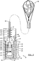
- the stone retrieval device is attached or connected to a capturing device 50, which is shown in greater detail in FIG. 4 .
- the capturing device 50 further a capturing basket 76, is positioned within the sheath 52 and an optional expandable cone 68.
- the capturing basket 76 includes a rod or wire 54 with a distal end 66 and a proximal end 67 attached to the smaller portion 30 of the first member 26.
- a pair of wires 58 and 60 are attached to the distal end 66 of the rod or wire 54.
- the ends of each of the wires 58 and 60 are attached to the distal end 66 such that the mid region of the wires 58 and 60 intersect at the distal most end of the capturing basket 76.
- the wires 58 and 60 are generally orthogonal to each other at the distal point of intersection for this particular arrangement. It is contemplated that various alternative basket wire configurations would work with the retraction force sensing handle portion of the present invention.
- the proximal region of the sheath 52 extends through the opening 41 of the housing 12, surrounds the extension 56 and is positioned within the coiled spring 42.
- the sheath 52 is attached or connected to the enlarged portion 40 of the first member 14.
- movement of the third member 26 relative to the first member 14 results in movement of the rod or wire 54 relative to the sheath 52.
- Different color indicators of the set of color indicators 45 viewed through the opening 44 indicates the pull force on the capturing basket 76.
- the pull-force sensor can be a sonic sensor, a tactile sensor, a pop-up flag or any other suitable sensor that indicates the pull force on the capturing basket 76.
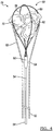
- the capturing basket 76 is initially collapsed within the cone 68 as the capturing device 50 is inserted into an anatomical region of a patient.
- the operator of the stone retrieval device 10 pushes on the positioner 18 distally such that the wires 58 and 60 exit a distal end 62 of the expandable cone 68.
- capturing basket 76 may alternatively extend from a sheath without a cone extending therefrom at a distal end. It is contemplated that a distal end of sheath may have a diameter equal to the diameter of the sheath along its length.
- the operator pulls on the positioner 18 proximally to draw the stone fragments 70 into the cone 68, which causes the cone 68 to expand.
- the distal end 62 of the cone 68 is configured to expand to a maximum predetermined size.
- the second member 16 moves proximally relative to the first member 16 such that the protrusion 34 eventually engages with one of the notches of the set of notches 36 associated the first member 14. Further, the proximal movement of the second member 14 also results in movement of the second member 14 relative to the third member 26. Such movement results in engagement of the protrusion 34 with the protrusion 32 embedded in the third member 26 and compression of the coiled spring 38. As described earlier, engagement of the protrusion 34 with the protrusion 36 and with one of the notches of the set of notches 36 locks the third member 26 and the second member 16 with the first member 14 in a locked position ( FIG. 2 ).
- the operator pushes on the positioner 18 such that the protrusion 34 becomes unlocked from the set of notches 36 and the coiled spring 38 pushes the third member 26 proximally relative to the second member 16 to unengage the protrusion 34 from the protrusion 32.
- a first color indicator such as a light color
- a second color indicator such as a darker color, may serve as a warning to the operator that the pull force on the stone fragments is approaching a maximum limit.
- a third color indicator such as a darkest color of the set of color indicators, may indicate to the operator that the pulls force is at the maximum limit and any additional pull force may damage the patient's ureter. Reducing the pull force results in the coiled spring 42 pushing the first member proximally relative to the housing 12 such that the lighter colored indicators of the set of indicators 45 are viewed through the opening 44 to indicate to the operator that the pull force on the capturing basket 76 has been reduced to a desired level.
- a stone retrieval device may comprise: a sheath; a stone retrieval basket including a distal region with a plurality of basket wires and a proximal region with one or more core wires, the stone retrieval basket being contained within the sheath and movable out of a distal opening of the sheath to cause the plurality of basket wires to open into a basket shape; a lock mechanism for locking the position of the stone retrieval basket with respect to the position of the sheath; and a basket force controller including a first control stage and a second control stage, wherein the first control stage includes a sensor for measuring force on the stone retrieval basket when the lock mechanism is in an unlocked position and the second control stage includes a sensor for measuring force on the stone retrieval basket when the lock mechanism is in a locked position.
- the lock mechanism may be a ratchet mechanism.
- the ratchet mechanism may include a first protrusion associated with a first member and a set of notches associated with a second member, the first member being contained in the second member and movable relative to the second member, the first protrusion being engaged with one notch of the set of notches when the lock mechanism is in the locked position.
- the one or more core wires may be attached to a third member contained in the first member, the third member being movable relative to the first member and including a second protrusion, the second protrusion being engaged with the first protrusion when the lock mechanism is in the locked position.
- movement of the third member relative to the first member pulls the plurality of basket wires into the distal opening of the sheath.
- the first control stage sensor may be a visual indicator with a first color.
- the second control stage sensor may be a visual indicator with a second color that is different than the first color.
- At least one of the sensors of the first control stage and the second control stage may be a pop-up flag.
- At least one of the sensors of the first control stage and the second control stage may be a tactile sensor.
- At least one of the sensors of the first control stage and the second control stage may be a sonic sensor.
- the stone retrieval device may further comprise an automatic release mechanism that releases the stone retrieval basket when the force on the stone retrieval basket exceeds a predetermined maximum force.
- the automatic release mechanism may be resettable after releasing the stone retrieval basket.
- a method of determining a force on a stone retrieval basket may comprise: capturing a stone with the stone retrieval basket; and utilizing a sensor to determine if the force on the stone retrieval basket exceeds a predetermined maximum force.
- the sensor may be a visual sensor.
- the method may further comprise releasing the stone retrieval basket when the force on the stone retrieval basket exceeds the predetermined maximum force.
Abstract
Description
- This application claims the benefit of
U.S. Provisional Patent Application No. 62/184,623, filed on June 25, 2015 - The present disclosure relates to a medical device. More specifically, the present disclosure relates to a medical device for capturing one or more stone fragments.
- The statements in this section merely provide background information related to the present disclosure and may or may not constitute prior art.
- During ureteroscopy or percutaneous nephrolithotomy (PCNL) procedures, baskets are often employed to capture and retrieve stone fragments from a patient's anatomy. After the stone fragments have been removed from the patient and released from the basket, the basket is re-inserted one or more times into the patient's anatomy to remove all or most of the remaining stone fragments. In some instances, however, stone fragments that are too large are captured in the basket, which may result in the basket getting stuck in the ureter or access sheath. If the basket can be pushed back, some fragments can be released and the basket can then be pulled out of the patient. If the basket is completely stuck, the basket can be cut apart from the basket handle and sheath, or a small laser fiber may be inserted into the patient so that laser energy can be utilized to break up the stone fragments. In any case, if the basket is damaged, a new basket has to be employed to complete the medical procedure, which may increase the surgical time and costs.
- Among the literature that can pertain to this technology include the following patent documents and published patent applications:
US 7,645,283 ,US 5,944,728 ,US 2005/0261705 , andDE69828984 , the entire contents of which are incorporated herein by reference for all purposes. - Accordingly, to reduce surgical cost and time, there is a need for a stone retrieval device that prevents the basket from getting stuck in the ureter to minimize trauma to the ureter during retrieval of stone fragments.
- The present invention provides an improved medical device for capturing one or more stone fragments and a method of using such a device.
- In one aspect, a stone retrieval device includes a sheath and a stone retrieval basket that includes a distal region with a plurality of basket wires and a proximal region with one or more core wires. The stone retrieval basket is contained within the sheath and is movable out a distal opening of the sheath to cause the plurality of basket wires to open into a basket shape. The stone retrieval device further includes a lock mechanism that locks the position of the stone retrieval basket with respect to the position of the sheath and a basket force controller that includes a first control stage and a second control stage. The first control stage includes a sensor for measuring force on the stone retrieval basket when the lock mechanism is in an unlocked position, and the second control stage includes a sensor for measuring force on the stone retrieval basket when the lock mechanism is in a locked position.
- The stone retrieval device may be further characterized by one or any combination of the features described herein, such as, for example: the lock mechanism is a ratchet mechanism; the ratchet mechanism includes a first protrusion associated with a first member and a set of notches associated with a second member, the first member being contained in the second member and movable relative to the second member, the first protrusion being engaged with one notch of the set of notches when the lock mechanism is in the locked position; the one or more core wires is attached to a third member contained in the first member, the third member being movable relative to the first member and including a second protrusion, the second protrusion being engaged with the first protrusion when the lock mechanism is in the locked position; movement of the third member relative to the first member pulls the plurality of basket wires into the distal opening of the sheath; the first control stage sensor is a visual indicator with a first color; the second control stage sensor is a visual indicator with a second color that is different than the first color; at least one of the sensors of the first control stage and the second control stage is a pop-up flag; at least one of the sensors of the first control stage and the second control stage is a tactile sensor; at least one of the sensors of the first control stage and the second control stage is a sonic sensor; the stone retrieval device further includes an automatic release mechanism that releases the stone retrieval basket when the force on the stone retrieval basket exceeds a predetermined maximum force; and the automatic release mechanism is resettable after releasing the stone retrieval basket.
- In another aspect, the present disclosure provides a method of determining a force on a stone retrieval basket including one or more of the following steps: capturing a stone with the stone retrieval basket; and utilizing a sensor to determine if the force on the stone retrieval basket exceeds a predetermined maximum force. The method may be further characterized by one or any combination of the features described herein, such as, for example: the sensor is visual sensor; and the method further includes releasing the stone retrieval basket when the force on the stone retrieval basket exceeds the predetermined maximum force.
- Further features, advantages, and areas of applicability will become apparent from the description provided herein. It should be understood that the description and specific examples are intended for purposes of illustration only and are not intended to limit the scope of the present disclosure.
- The drawings described herein are for illustration purposes only and are not intended to limit the scope of the present disclosure in any way. The components in the figures are not necessarily to scale, emphasis instead being placed upon illustrating the principles of the invention. Moreover, in the figures, like reference numerals designate corresponding parts throughout the views. In the drawings:
-
FIG. 1 is side cross-sectional view of a stone retrieval device in accordance with the principles of the present invention; -
FIG. 2 is a side cross-sectional view of the stone retrieval device shown inFIG. 1 when the device is in a locked position; -
FIG. 3 is a side cross-sectional view of the stone retrieval device shown inFIG. 1 when the device is applying a maximum pull force on one or more stone fragments; and -
FIG. 4 is a partial cross-sectional view of a basket device employed with the stone retrieval device shown inFIG. 1 in accordance with the principles of the present invention. - The following description is merely exemplary in nature and is not intended to limit the present disclosure, application, or uses.
- Referring now to the drawings, a stone retrieval device embodying the principles of the present invention is illustrated in
FIGs. 1 through 3 and designated at 10. Thestone retrieval device 10 includes ahousing 12, afirst member 14 contained within aspace 15 of thehousing 12, asecond member 16 contained within aspace 17 thefirst member 14, and athird member 26 contained within a space 27 thesecond member 16. Thethird member 26 includes an enlargedportion 28 and asmaller portion 30. - The
third member 26 is able to slide back and forth within thesecond member 16, and aprotrusion 32 embedded in the enlargedportion 28 selectively engages with aprotrusion 34 embedded in thesecond member 16. Abiasing member 38, such as, for example, a coiled spring, is positioned about thesmaller portion 30. The biasingmember 38 is arranged to urge thethird member 26 away from an opening 29 of thesecond member 16. - The
second member 16 is arranged to slide back and forth within thespace 17 of thefirst member 14. Theprotrusion 34 extends outwardly from thesecond member 16 such that theprotrusion 34 selectively engages with a notch of a set ofnotches 36 located on an inner surface of thefirst member 14. Hence, engagement of theprotrusion 32 with theprotrusion 34 and engagement of theprotrusion 34 with one of the notches of the set ofnotches 36 operates as a ratchet or locking mechanism to lock the position of thethird member 26 and thesecond member 16 relative to thefirst member 14 in a locked position. When theprotrusion 34 is unengaged with any of the notches of the set ofnotches 36. Thesecond member 16, and consequently, thethird member 26, are in an unlocked position relative to thefirst member 14. - A
positioner 18 includes anextension 22 that extends through an opening 24 of thehousing 12 and an opening 25 of thefirst member 14. Theextension 22 is attached to thesecond member 16. An operator of thestone retrieval device 10, such as a physician, can therefore place, for example, a thumb on anindentation 20 of thepositioner 18 and push or pull on thepositioner 18 to move thesecond member 16 relative to thefirst member 14 and thehousing 12. - In certain arrangements, the
stone retrieval device 10 includes a sensor such as, for example, a pull-force sensor with anopening 44 associated with thehousing 12 and a set ofcolor indicators 45 embedded in an enlargedportion 40 of thefirst member 14 that the operator can view through theopening 44. Accordingly, as thefirst member 14 slides within thespace 15 of thehousing 12. Different colored indicators of the set ofindicators 45 are observed through theopening 44. Another biasing member such as, for example, a coiledspring 42 is positioned about anextension 56 that extends from the enlargedportion 40 of thefirst member 14. The biasingmember 42 is arranged to urge thefirst member 14 away from an opening 41 of thehousing 12. - In various arrangements, the stone retrieval device is attached or connected to a capturing
device 50, which is shown in greater detail inFIG. 4 . The capturingdevice 50, further a capturingbasket 76, is positioned within thesheath 52 and an optionalexpandable cone 68. The capturingbasket 76 includes a rod orwire 54 with adistal end 66 and a proximal end 67 attached to thesmaller portion 30 of thefirst member 26. A pair ofwires distal end 66 of the rod orwire 54. Specifically, the ends of each of thewires distal end 66 such that the mid region of thewires basket 76. As shown inFIG. 4 , thewires - In addition to surrounding the rod or
wire 54, the proximal region of thesheath 52 extends through the opening 41 of thehousing 12, surrounds theextension 56 and is positioned within thecoiled spring 42. Thesheath 52 is attached or connected to the enlargedportion 40 of thefirst member 14. Thus, movement of thethird member 26 relative to thefirst member 14 results in movement of the rod orwire 54 relative to thesheath 52. Different color indicators of the set ofcolor indicators 45 viewed through theopening 44 indicates the pull force on the capturingbasket 76. Rather than color indicators, the pull-force sensor can be a sonic sensor, a tactile sensor, a pop-up flag or any other suitable sensor that indicates the pull force on the capturingbasket 76. - When the capturing
device 50 includes theoptional cone 68, the capturingbasket 76 is initially collapsed within thecone 68 as the capturingdevice 50 is inserted into an anatomical region of a patient. After the capturingbasket 76 and thecone 68 have been positioned in the anatomical region containing stone fragments, the operator of thestone retrieval device 10 pushes on thepositioner 18 distally such that thewires distal end 62 of theexpandable cone 68. It is contemplated that capturingbasket 76 may alternatively extend from a sheath without a cone extending therefrom at a distal end. It is contemplated that a distal end of sheath may have a diameter equal to the diameter of the sheath along its length. After the stone fragments 70 have been captured by thewires positioner 18 proximally to draw the stone fragments 70 into thecone 68, which causes thecone 68 to expand. Thedistal end 62 of thecone 68 is configured to expand to a maximum predetermined size. - As the operator of the
stone retrieval device 10 pulls thepositioner 18 distally, thesecond member 16 moves proximally relative to thefirst member 16 such that theprotrusion 34 eventually engages with one of the notches of the set ofnotches 36 associated thefirst member 14. Further, the proximal movement of thesecond member 14 also results in movement of thesecond member 14 relative to thethird member 26. Such movement results in engagement of theprotrusion 34 with theprotrusion 32 embedded in thethird member 26 and compression of the coiledspring 38. As described earlier, engagement of theprotrusion 34 with theprotrusion 36 and with one of the notches of the set ofnotches 36 locks thethird member 26 and thesecond member 16 with thefirst member 14 in a locked position (FIG. 2 ). To unlock the members, the operator pushes on thepositioner 18 such that theprotrusion 34 becomes unlocked from the set ofnotches 36 and thecoiled spring 38 pushes thethird member 26 proximally relative to thesecond member 16 to unengage theprotrusion 34 from theprotrusion 32. - During the stone removal procedure, the operator can view the
color indicators 45 through theopening 44. A first color indicator, such as a light color, can indicate to the operator that the pull force on the stone fragments 70 with not cause trauma or damage to the patient's ureter. As the operator pulls on thehousing 12 when the stone retrieval device is in the locked positions, the operator continues to view thecolor indicators 45 through theopening 44. Additional pull force moves thefirst member 14 distally relative to thehousing 12, resulting in compression of the coiledspring 42 and movement of the set ofcolor indicators 45 relative to theopening 44. A second color indicator, such as a darker color, may serve as a warning to the operator that the pull force on the stone fragments is approaching a maximum limit. A third color indicator, such as a darkest color of the set of color indicators, may indicate to the operator that the pulls force is at the maximum limit and any additional pull force may damage the patient's ureter. Reducing the pull force results in thecoiled spring 42 pushing the first member proximally relative to thehousing 12 such that the lighter colored indicators of the set ofindicators 45 are viewed through theopening 44 to indicate to the operator that the pull force on the capturingbasket 76 has been reduced to a desired level. - A stone retrieval device may comprise: a sheath; a stone retrieval basket including a distal region with a plurality of basket wires and a proximal region with one or more core wires, the stone retrieval basket being contained within the sheath and movable out of a distal opening of the sheath to cause the plurality of basket wires to open into a basket shape; a lock mechanism for locking the position of the stone retrieval basket with respect to the position of the sheath; and a basket force controller including a first control stage and a second control stage, wherein the first control stage includes a sensor for measuring force on the stone retrieval basket when the lock mechanism is in an unlocked position and the second control stage includes a sensor for measuring force on the stone retrieval basket when the lock mechanism is in a locked position.
- The lock mechanism may be a ratchet mechanism. In particular wherein the ratchet mechanism may include a first protrusion associated with a first member and a set of notches associated with a second member, the first member being contained in the second member and movable relative to the second member, the first protrusion being engaged with one notch of the set of notches when the lock mechanism is in the locked position. Especially wherein the one or more core wires may be attached to a third member contained in the first member, the third member being movable relative to the first member and including a second protrusion, the second protrusion being engaged with the first protrusion when the lock mechanism is in the locked position. Preferably wherein movement of the third member relative to the first member pulls the plurality of basket wires into the distal opening of the sheath.
- 6. The first control stage sensor may be a visual indicator with a first color. In particular wherein the second control stage sensor may be a visual indicator with a second color that is different than the first color.
- At least one of the sensors of the first control stage and the second control stage may be a pop-up flag.
- At least one of the sensors of the first control stage and the second control stage may be a tactile sensor.
- At least one of the sensors of the first control stage and the second control stage may be a sonic sensor.
- The stone retrieval device may further comprise an automatic release mechanism that releases the stone retrieval basket when the force on the stone retrieval basket exceeds a predetermined maximum force. In particular wherein the automatic release mechanism may be resettable after releasing the stone retrieval basket.
- A method of determining a force on a stone retrieval basket may comprise: capturing a stone with the stone retrieval basket; and utilizing a sensor to determine if the force on the stone retrieval basket exceeds a predetermined maximum force.
- The sensor may be a visual sensor.
- The method may further comprise releasing the stone retrieval basket when the force on the stone retrieval basket exceeds the predetermined maximum force.
- The description of the invention is merely exemplary in nature and variations that do not depart from the gist of the invention are intended to be within the scope of the invention. Such variations are not to be regarded as a departure from the spirit and scope of the invention.
Claims (15)
- A stone retrieval device comprising;
a stone retrieval basket configured to capture a stone;
a force sensor including an indicator, wherein the force sensor measures a force on the stone retrieval basket to determine if the force on the stone retrieval basket traverses a threshold force, and to provide an indication via the indicator when the threshold force is traversed. - The stone retrieval device of claim 1, wherein the indicator is one of visual, pop-up flag, tactile or sonic.
- The stone retrieval device of claim 1 or claim 2, wherein traversing the threshold force includes exceeding a predetermined maximum force.
- The stone retrieval device of any one of the preceding claims further comprising a housing and a locking mechanism that is engageable to lock a position of the stone retrieval basket relative to the housing.
- The stone retrieval device of claim 4, further comprising a sheath having a distal opening, wherein the stone retrieval basket is configured to be stored in the sheath and is movable out of the distal opening of the sheath to cause one or more basket wires to open into a basket shape.
- The stone retrieval device of claim 4 or claim 5, wherein the locking mechanism comprises a ratchet mechanism.
- The stone retrieval device of claim 6, wherein the ratchet mechanism includes a first protrusion associated with a first member and a set of notches associated with a second member, the first member located in the second member and movable relative to the second member, the first protrusion being engaged with a notch of the set of notches when the locking mechanism is in a locked position.
- The stone retrieval device of claim 7, wherein the stone retrieval basket includes a distal region including one or more basket wires and a proximal region including one or more core wires, the stone retrieval basket located within a sheath and movable out of a distal opening of the sheath to cause the one or more basket wires to open into a basket shape.
- The stone retrieval device of claim 8, wherein the one or more core wires are attached to a third member located in the first member, the third member being movable relative to the first member and including a second protrusion, the second protrusion being engaged with the first protrusion when the locking mechanism is in the locked position.
- The stone retrieval device of claim 9, wherein moving the third member relative to the first member pulls the one or more basket wires into the distal opening of the sheath.
- A method of determining a force on a stone retrieval basket comprising:capturing a stone with the stone retrieval basket;measuring the force on the stone retrieval basket with a force sensor;determining if the force on the stone retrieval basket traverses a threshold force; andproviding an indication to a user of the stone retrieval basket when the threshold force is traversed.
- The method of claim 11, wherein the indication is one of visual, pop-up flag, tactile or sonic.
- The method of claim 11 or claim 12, wherein traversing the threshold force includes exceeding a predetermined maximum force.
- The method of claim 13, further comprising releasing the stone retrieval basket if the force on the stone retrieval basket exceeds the predetermined maximum force.
- The method of claim 11, wherein capturing the stone comprises engaging a locking mechanism, in particular wherein engaging the locking mechanism includes engaging a ratchet mechanism, especially wherein the ratchet mechanism includes a first protrusion associated with a first member and a set of notches associated with a second member, the first member located in the second member and movable relative to the second member, the first protrusion being engaged with one notch of the set of notches when the locking mechanism is in a locked position, preferably wherein the stone retrieval basket includes a distal region with a plurality of basket wires and a proximal region with one or more core wires, the stone retrieval basket storable in a sheath and movable out of a distal opening of the sheath to cause the plurality of basket wires to open into a basket shape, most preferably wherein the method further comprises engaging the one or more core wires attached to a third member contained in the first member, the third member being movable relative to the first member and including a second protrusion, the second protrusion being engaged with the first protrusion when the locking mechanism is in the locked position, especially wherein moving the third member relative to the first member pulls the plurality of basket wires into the distal opening of the sheath.
Applications Claiming Priority (3)
| Application Number | Priority Date | Filing Date | Title |
|---|---|---|---|
| US201562184623P | 2015-06-25 | 2015-06-25 | |
| PCT/US2016/013023 WO2016209318A1 (en) | 2015-06-25 | 2016-01-12 | Retraction force sensing basket |
| EP16701895.1A EP3297548B1 (en) | 2015-06-25 | 2016-01-12 | Retraction force sensing basket |
Related Parent Applications (2)
| Application Number | Title | Priority Date | Filing Date |
|---|---|---|---|
| EP16701895.1A Division EP3297548B1 (en) | 2015-06-25 | 2016-01-12 | Retraction force sensing basket |
| EP16701895.1A Division-Into EP3297548B1 (en) | 2015-06-25 | 2016-01-12 | Retraction force sensing basket |
Publications (1)
| Publication Number | Publication Date |
|---|---|
| EP3689275A1 true EP3689275A1 (en) | 2020-08-05 |
Family
ID=55237920
Family Applications (2)
| Application Number | Title | Priority Date | Filing Date |
|---|---|---|---|
| EP20164471.3A Pending EP3689275A1 (en) | 2015-06-25 | 2016-01-12 | Retraction force sensing basket |
| EP16701895.1A Active EP3297548B1 (en) | 2015-06-25 | 2016-01-12 | Retraction force sensing basket |
Family Applications After (1)
| Application Number | Title | Priority Date | Filing Date |
|---|---|---|---|
| EP16701895.1A Active EP3297548B1 (en) | 2015-06-25 | 2016-01-12 | Retraction force sensing basket |
Country Status (5)
| Country | Link |
|---|---|
| US (3) | US9724115B2 (en) |
| EP (2) | EP3689275A1 (en) |
| JP (2) | JP6557742B2 (en) |
| CN (1) | CN108124423B (en) |
| WO (1) | WO2016209318A1 (en) |
Families Citing this family (13)
| Publication number | Priority date | Publication date | Assignee | Title |
|---|---|---|---|---|
| US10219864B2 (en) | 2013-04-16 | 2019-03-05 | Calcula Technologies, Inc. | Basket and everting balloon with simplified design and control |
| US9232956B2 (en) | 2013-04-16 | 2016-01-12 | Calcula Technologies, Inc. | Device for removing kidney stones |
| US10188411B2 (en) | 2013-04-16 | 2019-01-29 | Calcula Technologies, Inc. | Everting balloon for medical devices |
| US10888346B2 (en) * | 2014-05-18 | 2021-01-12 | Legacy Ventures LLC | Clot retrieval system |
| JP6557742B2 (en) | 2015-06-25 | 2019-08-07 | ジャイラス・エイシーエムアイ・インコーポレイテッド | Retraction force detection basket |
| US11051853B2 (en) | 2015-09-04 | 2021-07-06 | The Trustees Of The University Of Pennsylvania | Systems and methods for percutaneous removal of objects from an internal body space |
| JP7246319B2 (en) * | 2017-04-13 | 2023-03-27 | ボストン サイエンティフィック サイムド,インコーポレイテッド | capture device |
| US9743944B1 (en) * | 2017-04-24 | 2017-08-29 | Calcula Technologies, Inc. | Stone retrieval balloon catheter |
| CN111936075A (en) * | 2018-04-12 | 2020-11-13 | 逸吉恩哆股份公司 | Self-propelled endoscope system and control method thereof |
| CN108742803A (en) * | 2018-07-04 | 2018-11-06 | 佛山市墨宸智能科技有限公司 | A kind of spiral mesh basket mondet forceps |
| CN111358528B (en) * | 2020-03-23 | 2021-01-19 | 中国人民解放军总医院第八医学中心 | Hepatobiliary calculus removing device |
| KR20230018467A (en) * | 2020-06-01 | 2023-02-07 | 아우리스 헬스, 인코포레이티드 | Fixation device management |
| KR102188958B1 (en) * | 2020-08-24 | 2020-12-09 | 주식회사 이지엔도서지컬 | Basket actuator and surgical device comprising the same |
Citations (13)
| Publication number | Priority date | Publication date | Assignee | Title |
|---|---|---|---|---|
| DE3216178A1 (en) * | 1982-04-30 | 1983-11-03 | Helmut Prof. Dr.med. 8720 Schweinfurt Koch | Mechanical lithotriptor with controllable tensile force |
| EP0324641A2 (en) * | 1988-01-13 | 1989-07-19 | BAXTER INTERNATIONAL INC. (a Delaware corporation) | Shear force gauge |
| US5573530A (en) * | 1994-12-15 | 1996-11-12 | Cabot Technology Corporation | Handle for a surgical instrument including a manually actuated brake |
| US5944728A (en) | 1998-04-23 | 1999-08-31 | Boston Scientific Corporation | Surgical retrieval basket with the ability to capture and release material |
| US5957932A (en) * | 1996-04-30 | 1999-09-28 | Boston Scientific Corporation | Calculus removal |
| WO2001060235A2 (en) * | 2000-02-18 | 2001-08-23 | Fogarty Thomas J M D | Improved device for accurately marking tissue |
| US20040199200A1 (en) * | 2003-04-07 | 2004-10-07 | Scimed Life Systems, Inc. | Beaded basket retrieval device |
| US20050261705A1 (en) | 2004-05-21 | 2005-11-24 | Gist Christopher W | Device to remove kidney stones |
| DE69828984T2 (en) | 1997-04-29 | 2006-03-30 | Raymond F. Lippitt | RINGING EXPANDABLE AND RETROFACTIVE MECHANISM FOR GRIPPING AND SOLVING |
| WO2009042451A2 (en) * | 2007-09-26 | 2009-04-02 | Wilson-Cook Medical Inc. | Wire capture surgical device with fixable handle |
| US7645283B2 (en) | 2001-01-08 | 2010-01-12 | Boston Scientific Scimed, Inc. | Retrieval basket with releasable tip |
| DE102009022867A1 (en) * | 2009-05-27 | 2010-12-02 | Endosmart Gesellschaft für Medizintechnik m.b.H. | Minimal-invasive medical tool for removing kidney stone, has cores movably arranged opposite to each other, and force limiter provided on operating element for limiting force that is transmitted during engagement process |
| WO2015134846A1 (en) * | 2014-03-07 | 2015-09-11 | The University Of Akron | Surgical apparatus with force sensor for extraction of substances within the body |
Family Cites Families (37)
| Publication number | Priority date | Publication date | Assignee | Title |
|---|---|---|---|---|
| US5084054A (en) * | 1990-03-05 | 1992-01-28 | C.R. Bard, Inc. | Surgical gripping instrument |
| US5425375A (en) * | 1993-09-09 | 1995-06-20 | Cardiac Pathways Corporation | Reusable medical device with usage memory, system using same |
| US5792164A (en) * | 1994-12-19 | 1998-08-11 | Lakatos; Nick | Surgical instrument |
| US5827304A (en) * | 1995-11-16 | 1998-10-27 | Applied Medical Resources Corporation | Intraluminal extraction catheter |
| US6096053A (en) * | 1996-05-03 | 2000-08-01 | Scimed Life Systems, Inc. | Medical retrieval basket |
| US7181261B2 (en) * | 2000-05-15 | 2007-02-20 | Silver James H | Implantable, retrievable, thrombus minimizing sensors |
| US6814739B2 (en) * | 2001-05-18 | 2004-11-09 | U.S. Endoscopy Group, Inc. | Retrieval device |
| US8021372B2 (en) * | 2001-07-05 | 2011-09-20 | Annex Medical, Inc. | Medical retrieval device with independent rotational means |
| CN100409818C (en) * | 2001-07-06 | 2008-08-13 | 周星 | Reusable temporary thrombus filter |
| US6695834B2 (en) * | 2002-01-25 | 2004-02-24 | Scimed Life Systems, Inc. | Apparatus and method for stone removal from a body |
| US8043303B2 (en) * | 2002-10-04 | 2011-10-25 | Cook Medical Technologies Llc | Handle for interchangeable medical device |
| WO2004032769A1 (en) * | 2002-10-04 | 2004-04-22 | Cook Urological, Incorporated | Rigid extractor with wire basket |
| US8285359B2 (en) * | 2003-11-26 | 2012-10-09 | General Electric Company | Method and system for retrospective gating using multiple inputs |
| JP2006255162A (en) * | 2005-03-17 | 2006-09-28 | Olympus Corp | Medical suture ligation unit |
| CA2605360C (en) * | 2005-04-21 | 2017-03-28 | Asthmatx, Inc. | Control methods and devices for energy delivery |
| EP1954195A1 (en) * | 2005-11-17 | 2008-08-13 | Koninklijke Philips Electronics N.V. | Vascular flow sensor with acoustic coupling detector |
| CA2655351A1 (en) * | 2006-06-26 | 2008-01-03 | Wilson-Cook Medical Inc. | Improved handle for lithotripsy basket device |
| US20090105798A1 (en) * | 2007-10-17 | 2009-04-23 | Abbott Laboratories Vascular Enterprises Limited | Handle for stepwise deployment |
| US8585713B2 (en) * | 2007-10-17 | 2013-11-19 | Covidien Lp | Expandable tip assembly for thrombus management |
| WO2009079509A2 (en) * | 2007-12-18 | 2009-06-25 | Boston Scientific Scimed, Inc. | Multi-functional medical device |
| JP2009165717A (en) * | 2008-01-18 | 2009-07-30 | Hoya Corp | Advance and retreat mechanism of slide member |
| US20100049137A1 (en) * | 2008-08-20 | 2010-02-25 | Cook Incorporated | Device for Crossing Occlusions and Method of Use Thereof |
| US20120247481A1 (en) * | 2009-10-02 | 2012-10-04 | Eastern Virginia Medical School | Cervical occluder |
| US8790353B2 (en) * | 2009-11-19 | 2014-07-29 | Medwork Medical Products And Services Gmbh | Device for mechanical lithotripsy and removal of calculi that form in the bile duct or in the urinary system |
| US8226580B2 (en) * | 2010-06-30 | 2012-07-24 | Biosense Webster (Israel), Ltd. | Pressure sensing for a multi-arm catheter |
| WO2012120490A2 (en) * | 2011-03-09 | 2012-09-13 | Neuravi Limited | A clot retrieval device for removing occlusive clot from a blood vessel |
| JP6174025B2 (en) * | 2011-08-18 | 2017-08-02 | アンカー オーソペディックス エックスティー インコーポレイテッドAnchor Orthopedics Xt Inc. | Bi-directional suture threader |
| WO2013109756A2 (en) * | 2012-01-17 | 2013-07-25 | Perflow Medical Ltd. | Method and apparatus for occlusion removal |
| CN202821511U (en) * | 2012-05-07 | 2013-03-27 | 王涛 | Thrombus breaking and taking device |
| US9801631B2 (en) * | 2012-11-14 | 2017-10-31 | St. Jude Medical Puerto Rico Llc | Sheath and balloon tensioner and locator systems and methods |
| CN104042292A (en) * | 2013-03-15 | 2014-09-17 | 柯惠Lp公司 | Surgical anastomosis device comprising assemblies capable of being repeatedly utilized |
| US9814618B2 (en) * | 2013-06-06 | 2017-11-14 | Boston Scientific Scimed, Inc. | Devices for delivering energy and related methods of use |
| US9808249B2 (en) | 2013-08-23 | 2017-11-07 | Ethicon Llc | Attachment portions for surgical instrument assemblies |
| US9801644B2 (en) * | 2014-01-03 | 2017-10-31 | Legacy Ventures LLC | Clot retrieval system |
| US9826998B2 (en) * | 2014-01-03 | 2017-11-28 | Legacy Ventures LLC | Clot retrieval system |
| US9808246B2 (en) | 2015-03-06 | 2017-11-07 | Ethicon Endo-Surgery, Llc | Method of operating a powered surgical instrument |
| JP6557742B2 (en) | 2015-06-25 | 2019-08-07 | ジャイラス・エイシーエムアイ・インコーポレイテッド | Retraction force detection basket |
-
2016
- 2016-01-12 JP JP2017565820A patent/JP6557742B2/en active Active
- 2016-01-12 CN CN201680036693.7A patent/CN108124423B/en active Active
- 2016-01-12 EP EP20164471.3A patent/EP3689275A1/en active Pending
- 2016-01-12 WO PCT/US2016/013023 patent/WO2016209318A1/en active Application Filing
- 2016-01-12 EP EP16701895.1A patent/EP3297548B1/en active Active
- 2016-05-17 US US15/156,715 patent/US9724115B2/en active Active
-
2017
- 2017-07-11 US US15/646,479 patent/US10349961B2/en active Active
-
2019
- 2019-06-05 US US16/432,156 patent/US11413053B2/en active Active
- 2019-07-12 JP JP2019130171A patent/JP6945599B2/en active Active
Patent Citations (13)
| Publication number | Priority date | Publication date | Assignee | Title |
|---|---|---|---|---|
| DE3216178A1 (en) * | 1982-04-30 | 1983-11-03 | Helmut Prof. Dr.med. 8720 Schweinfurt Koch | Mechanical lithotriptor with controllable tensile force |
| EP0324641A2 (en) * | 1988-01-13 | 1989-07-19 | BAXTER INTERNATIONAL INC. (a Delaware corporation) | Shear force gauge |
| US5573530A (en) * | 1994-12-15 | 1996-11-12 | Cabot Technology Corporation | Handle for a surgical instrument including a manually actuated brake |
| US5957932A (en) * | 1996-04-30 | 1999-09-28 | Boston Scientific Corporation | Calculus removal |
| DE69828984T2 (en) | 1997-04-29 | 2006-03-30 | Raymond F. Lippitt | RINGING EXPANDABLE AND RETROFACTIVE MECHANISM FOR GRIPPING AND SOLVING |
| US5944728A (en) | 1998-04-23 | 1999-08-31 | Boston Scientific Corporation | Surgical retrieval basket with the ability to capture and release material |
| WO2001060235A2 (en) * | 2000-02-18 | 2001-08-23 | Fogarty Thomas J M D | Improved device for accurately marking tissue |
| US7645283B2 (en) | 2001-01-08 | 2010-01-12 | Boston Scientific Scimed, Inc. | Retrieval basket with releasable tip |
| US20040199200A1 (en) * | 2003-04-07 | 2004-10-07 | Scimed Life Systems, Inc. | Beaded basket retrieval device |
| US20050261705A1 (en) | 2004-05-21 | 2005-11-24 | Gist Christopher W | Device to remove kidney stones |
| WO2009042451A2 (en) * | 2007-09-26 | 2009-04-02 | Wilson-Cook Medical Inc. | Wire capture surgical device with fixable handle |
| DE102009022867A1 (en) * | 2009-05-27 | 2010-12-02 | Endosmart Gesellschaft für Medizintechnik m.b.H. | Minimal-invasive medical tool for removing kidney stone, has cores movably arranged opposite to each other, and force limiter provided on operating element for limiting force that is transmitted during engagement process |
| WO2015134846A1 (en) * | 2014-03-07 | 2015-09-11 | The University Of Akron | Surgical apparatus with force sensor for extraction of substances within the body |
Also Published As
| Publication number | Publication date |
|---|---|
| US20160374702A1 (en) | 2016-12-29 |
| JP6945599B2 (en) | 2021-10-06 |
| US20170303945A1 (en) | 2017-10-26 |
| US9724115B2 (en) | 2017-08-08 |
| CN108124423A (en) | 2018-06-05 |
| CN108124423B (en) | 2020-12-04 |
| WO2016209318A1 (en) | 2016-12-29 |
| US11413053B2 (en) | 2022-08-16 |
| JP6557742B2 (en) | 2019-08-07 |
| US20190282248A1 (en) | 2019-09-19 |
| JP2019193867A (en) | 2019-11-07 |
| US10349961B2 (en) | 2019-07-16 |
| EP3297548A1 (en) | 2018-03-28 |
| EP3297548B1 (en) | 2020-05-06 |
| JP2018519055A (en) | 2018-07-19 |
Similar Documents
| Publication | Publication Date | Title |
|---|---|---|
| US11413053B2 (en) | Retraction force sensing basket | |
| US11717307B2 (en) | Medical device for capturing stone fragments | |
| EP3756608B1 (en) | Calculi removing device | |
| EP2544603B1 (en) | Obstruction removal assembly | |
| EP2213246B1 (en) | Expandable needle suture apparatus and associated handle assembly | |
| US9427244B2 (en) | Object capture device | |
| US20050251063A1 (en) | Safety device for sampling tissue | |
| JP2019193867A5 (en) | ||
| JP2010188068A (en) | Instrument for capturing thrombus in blood vessel | |
| US10987125B2 (en) | Capsule cutter | |
| US10368886B2 (en) | Surgical apparatus with force sensor for extraction of substances within the body | |
| US10105153B2 (en) | Multifunction retrieval devices and related methods | |
| EP3795099B1 (en) | Stent system | |
| WO2011143668A2 (en) | Animal control pole | |
| US20190275261A1 (en) | Safety locked needle | |
| US20220361858A1 (en) | Biopsy arrangements |
Legal Events
| Date | Code | Title | Description |
|---|---|---|---|
| PUAI | Public reference made under article 153(3) epc to a published international application that has entered the european phase |
Free format text: ORIGINAL CODE: 0009012 |
|
| STAA | Information on the status of an ep patent application or granted ep patent |
Free format text: STATUS: THE APPLICATION HAS BEEN PUBLISHED |
|
| AC | Divisional application: reference to earlier application |
Ref document number: 3297548 Country of ref document: EP Kind code of ref document: P |
|
| AK | Designated contracting states |
Kind code of ref document: A1 Designated state(s): AL AT BE BG CH CY CZ DE DK EE ES FI FR GB GR HR HU IE IS IT LI LT LU LV MC MK MT NL NO PL PT RO RS SE SI SK SM TR |
|
| STAA | Information on the status of an ep patent application or granted ep patent |
Free format text: STATUS: REQUEST FOR EXAMINATION WAS MADE |
|
| 17P | Request for examination filed |
Effective date: 20201014 |
|
| RBV | Designated contracting states (corrected) |
Designated state(s): AL AT BE BG CH CY CZ DE DK EE ES FI FR GB GR HR HU IE IS IT LI LT LU LV MC MK MT NL NO PL PT RO RS SE SI SK SM TR |
|
| STAA | Information on the status of an ep patent application or granted ep patent |
Free format text: STATUS: EXAMINATION IS IN PROGRESS |
|
| 17Q | First examination report despatched |
Effective date: 20230314 |
|
| P01 | Opt-out of the competence of the unified patent court (upc) registered |
Effective date: 20230520 |