EP3689271B1 - Left atrial appendage occluder and left atrial appendage occlusion device - Google Patents
Left atrial appendage occluder and left atrial appendage occlusion device Download PDFInfo
- Publication number
- EP3689271B1 EP3689271B1 EP18860656.0A EP18860656A EP3689271B1 EP 3689271 B1 EP3689271 B1 EP 3689271B1 EP 18860656 A EP18860656 A EP 18860656A EP 3689271 B1 EP3689271 B1 EP 3689271B1
- Authority
- EP
- European Patent Office
- Prior art keywords
- occlusion
- left atrial
- atrial appendage
- frame
- guiding member
- Prior art date
- Legal status (The legal status is an assumption and is not a legal conclusion. Google has not performed a legal analysis and makes no representation as to the accuracy of the status listed.)
- Active
Links
Images





Classifications
-
- A—HUMAN NECESSITIES
- A61—MEDICAL OR VETERINARY SCIENCE; HYGIENE
- A61B—DIAGNOSIS; SURGERY; IDENTIFICATION
- A61B17/00—Surgical instruments, devices or methods
- A61B17/12—Surgical instruments, devices or methods for ligaturing or otherwise compressing tubular parts of the body, e.g. blood vessels or umbilical cord
- A61B17/12022—Occluding by internal devices, e.g. balloons or releasable wires
- A61B17/12099—Occluding by internal devices, e.g. balloons or releasable wires characterised by the location of the occluder
- A61B17/12122—Occluding by internal devices, e.g. balloons or releasable wires characterised by the location of the occluder within the heart
-
- A—HUMAN NECESSITIES
- A61—MEDICAL OR VETERINARY SCIENCE; HYGIENE
- A61B—DIAGNOSIS; SURGERY; IDENTIFICATION
- A61B17/00—Surgical instruments, devices or methods
- A61B17/12—Surgical instruments, devices or methods for ligaturing or otherwise compressing tubular parts of the body, e.g. blood vessels or umbilical cord
- A61B17/12022—Occluding by internal devices, e.g. balloons or releasable wires
- A61B17/12099—Occluding by internal devices, e.g. balloons or releasable wires characterised by the location of the occluder
- A61B17/12109—Occluding by internal devices, e.g. balloons or releasable wires characterised by the location of the occluder in a blood vessel
-
- A—HUMAN NECESSITIES
- A61—MEDICAL OR VETERINARY SCIENCE; HYGIENE
- A61B—DIAGNOSIS; SURGERY; IDENTIFICATION
- A61B17/00—Surgical instruments, devices or methods
- A61B17/12—Surgical instruments, devices or methods for ligaturing or otherwise compressing tubular parts of the body, e.g. blood vessels or umbilical cord
- A61B17/12022—Occluding by internal devices, e.g. balloons or releasable wires
- A61B17/12131—Occluding by internal devices, e.g. balloons or releasable wires characterised by the type of occluding device
-
- A—HUMAN NECESSITIES
- A61—MEDICAL OR VETERINARY SCIENCE; HYGIENE
- A61B—DIAGNOSIS; SURGERY; IDENTIFICATION
- A61B17/00—Surgical instruments, devices or methods
- A61B17/12—Surgical instruments, devices or methods for ligaturing or otherwise compressing tubular parts of the body, e.g. blood vessels or umbilical cord
- A61B17/12022—Occluding by internal devices, e.g. balloons or releasable wires
- A61B17/12131—Occluding by internal devices, e.g. balloons or releasable wires characterised by the type of occluding device
- A61B17/1214—Coils or wires
- A61B17/12145—Coils or wires having a pre-set deployed three-dimensional shape
-
- A—HUMAN NECESSITIES
- A61—MEDICAL OR VETERINARY SCIENCE; HYGIENE
- A61B—DIAGNOSIS; SURGERY; IDENTIFICATION
- A61B17/00—Surgical instruments, devices or methods
- A61B17/12—Surgical instruments, devices or methods for ligaturing or otherwise compressing tubular parts of the body, e.g. blood vessels or umbilical cord
- A61B17/12022—Occluding by internal devices, e.g. balloons or releasable wires
- A61B17/12131—Occluding by internal devices, e.g. balloons or releasable wires characterised by the type of occluding device
- A61B17/12168—Occluding by internal devices, e.g. balloons or releasable wires characterised by the type of occluding device having a mesh structure
- A61B17/12172—Occluding by internal devices, e.g. balloons or releasable wires characterised by the type of occluding device having a mesh structure having a pre-set deployed three-dimensional shape
-
- A—HUMAN NECESSITIES
- A61—MEDICAL OR VETERINARY SCIENCE; HYGIENE
- A61B—DIAGNOSIS; SURGERY; IDENTIFICATION
- A61B17/00—Surgical instruments, devices or methods
- A61B17/12—Surgical instruments, devices or methods for ligaturing or otherwise compressing tubular parts of the body, e.g. blood vessels or umbilical cord
- A61B17/12022—Occluding by internal devices, e.g. balloons or releasable wires
- A61B17/12131—Occluding by internal devices, e.g. balloons or releasable wires characterised by the type of occluding device
- A61B17/12168—Occluding by internal devices, e.g. balloons or releasable wires characterised by the type of occluding device having a mesh structure
- A61B17/12177—Occluding by internal devices, e.g. balloons or releasable wires characterised by the type of occluding device having a mesh structure comprising additional materials, e.g. thrombogenic, having filaments, having fibers or being coated
-
- A—HUMAN NECESSITIES
- A61—MEDICAL OR VETERINARY SCIENCE; HYGIENE
- A61F—FILTERS IMPLANTABLE INTO BLOOD VESSELS; PROSTHESES; DEVICES PROVIDING PATENCY TO, OR PREVENTING COLLAPSING OF, TUBULAR STRUCTURES OF THE BODY, e.g. STENTS; ORTHOPAEDIC, NURSING OR CONTRACEPTIVE DEVICES; FOMENTATION; TREATMENT OR PROTECTION OF EYES OR EARS; BANDAGES, DRESSINGS OR ABSORBENT PADS; FIRST-AID KITS
- A61F2/00—Filters implantable into blood vessels; Prostheses, i.e. artificial substitutes or replacements for parts of the body; Appliances for connecting them with the body; Devices providing patency to, or preventing collapsing of, tubular structures of the body, e.g. stents
- A61F2/02—Prostheses implantable into the body
- A61F2/04—Hollow or tubular parts of organs, e.g. bladders, tracheae, bronchi or bile ducts
- A61F2/06—Blood vessels
-
- A—HUMAN NECESSITIES
- A61—MEDICAL OR VETERINARY SCIENCE; HYGIENE
- A61B—DIAGNOSIS; SURGERY; IDENTIFICATION
- A61B17/00—Surgical instruments, devices or methods
- A61B17/12—Surgical instruments, devices or methods for ligaturing or otherwise compressing tubular parts of the body, e.g. blood vessels or umbilical cord
- A61B17/12022—Occluding by internal devices, e.g. balloons or releasable wires
- A61B2017/1205—Introduction devices
-
- A—HUMAN NECESSITIES
- A61—MEDICAL OR VETERINARY SCIENCE; HYGIENE
- A61B—DIAGNOSIS; SURGERY; IDENTIFICATION
- A61B17/00—Surgical instruments, devices or methods
- A61B17/12—Surgical instruments, devices or methods for ligaturing or otherwise compressing tubular parts of the body, e.g. blood vessels or umbilical cord
- A61B17/12022—Occluding by internal devices, e.g. balloons or releasable wires
- A61B2017/1205—Introduction devices
- A61B2017/12054—Details concerning the detachment of the occluding device from the introduction device
-
- A—HUMAN NECESSITIES
- A61—MEDICAL OR VETERINARY SCIENCE; HYGIENE
- A61B—DIAGNOSIS; SURGERY; IDENTIFICATION
- A61B17/00—Surgical instruments, devices or methods
- A61B17/12—Surgical instruments, devices or methods for ligaturing or otherwise compressing tubular parts of the body, e.g. blood vessels or umbilical cord
- A61B17/12022—Occluding by internal devices, e.g. balloons or releasable wires
- A61B2017/1205—Introduction devices
- A61B2017/12054—Details concerning the detachment of the occluding device from the introduction device
- A61B2017/12095—Threaded connection
Definitions
- the present application relates to the field of medical instruments and, in particular, to a left atrial appendage occluder and a left atrial appendage occlusion device.
- Atrial Fibrillation is the common continuous arrhythmia in clinic.
- the incidence of AF in the general population is 0.5-1.3%.
- the main hazard of AF is to promote thrombosis.
- Complications such as stroke and peripheral vascular embolization caused by thrombus detachment significantly increase the disability and fatality rate.
- Stroke is the most common and devastating complication of AF.
- About 15 million people worldwide suffer from stroke each year, 20-25% of which are attributed to AF.
- the study suggests that 60% of patients with rheumatic heart disease have a cardiogenic thrombus from the left atrial appendage, and more than 90% of thrombi in the patients with non-valvular AF are formed in the left atrial appendage. Therefore, the intervention of the left atrial appendage to prevent thromboembolism in patients with AF, especially stroke, has important theoretical and clinical significance.
- Anticoagulant therapy is a standard method for preventing complications of stroke and AF at present, but has certain limitations. Therefore, the use of safer and more effective measures to prevent AF and stroke is of great significance.
- medical interventions are mostly used to occlude the left atrial appendage.
- the commonly used left atrial appendage occluders comprise a single plug type occluder represented by WATCHMAN and a plug-and-disc type left atrial appendage occluder represented by AMPLATZER Cardiac Plug (ACP).
- the plug type left atrial appendage occluder has a nickel-titanium alloy frame with a self-expanding structure and barbs fixed around.
- the surface of the occluder towards atrial is covered with a porous polytetrafluoroethylene membrane for blood inflow outflow in the left atrial appendage.
- the plug type left atrial appendage occluder When the plug type left atrial appendage occluder has been plugged into the left atrial appendage, the entrance of left atrial appendage cannot be completely occluded since the shape of the entrance of the left atrial appendage is irregular, and the occluder has a limited deformability. Therefore, it is difficult to eliminate the thrombus caused by leakage of the left atrial appendage due to AF.
- the left atrial appendage has different structures and depths, and in addition, a multi-cavity structure.
- the plug type occluder is unable to fully adapt to the anatomical structures of all left atrial appendages as well as to achieve a stable fixation.
- the plug-and-disc type left atrial appendage occluder is a two-disc type device consisting of a butterfly blade which would be placed in the left atrial appendage and a butterfly cap.
- the butterfly blade and the butterfly cap are connected by a concave waist.
- the butterfly blade is placed in the left atrial appendage to prevent the occluder from shifting.
- the butterfly cap seals the entrance of the left atrial appendage.
- the plug-and-disc type left atrial appendage occluder has a structure in which the sealing disc and the fixed disc are integrated, and cannot be completely deformed independently. After the plug is plugged into the left atrial appendage, the disc portion adhered to the entrance of the left atrial appendage is subjected to the pull of the plug portion, so that the disc portion cannot fully fit to the entrance of the left atrial appendage, and thus it is difficult to achieve an optimal occluding effect. Moreover, since the length adjustments of the plug portion and the disc portion are limited, it is difficult to achieve the optimal fixation and blood flow blockage, and the disc structure does not adapt to different lumen shapes of the left atrial appendage.
- WO02/071977A2 discloses a left atrial appendage occluder having elastic cover and anchoring substructures.
- the left atrial appendage occluder has H-shaped cross sections and seals the appendages by pinching an annular region of ostium tissue between the cover and the anchoring substructures.
- US2017/042549A1 discloses a left atrial appendage occlusion device comprising at least one deployable tissue anchor that is configured to deploy from a constrained configuration to a deployed configuration and retractable from the deployed configuration to a retracted configuration within the body.
- US2017/156840A1 discloses a medical device includes an occluder portion having an occluder eyelet and an anchor portion having an anchor eyelet, the anchor eyelet hingeably coupled to the occluder eyelet to make the anchor portion capable of moving between a retracted position and a deployed position upon the occluder portion being in an expanded position.
- CN101460102A also discloses an implantable device for the left atrium of a heart, wherein at least the one portion in the secondary form has a first part facing outwardly away from the other portion and a second part which deploys first from the primary form into the secondary form and which is folded back in a direction towards the other portion on to the first part.
- the application provides a left atrial appendage occluder according to claim 1.
- the distal end of the guiding member is a blunt end.
- the guiding member is a guide wire having a ball head or a hook at the distal end thereof.
- the occlusion member comprises a frame, a polymer membrane covering the frame and anchors fixed on the frame, and the elastic opening is formed by means of the polymer membrane.
- the polymer membrane comprises a plurality of membrane sheets and interstices between the plurality of membrane sheets form the elastic opening, or the polymer membrane comprises a plurality of interlaced membrane wires and interstices between the plurality of interlaced membrane wires form the elastic opening.
- the present application also provides a left atrial appendage occlusion device according to claim 7.
- the guiding member is a guide wire having a blunt end at a distal end thereof.
- the occlusion member has an elastic opening, and the guiding member passes through the elastic opening and is removable out from the elastic opening.
- the elastic opening contracts upon removal of the guiding member from the elastic opening.
- the occlusion member comprises a frame, a polymer membrane covering the frame and anchors fixed on the frame, and the elastic opening is formed by means of the polymer membrane.
- the polymer membrane comprises a plurality of membrane sheets and interstices between the plurality of membrane sheets form the elastic opening, or the polymer membrane comprises a plurality of interlaced membrane wires and interstices between the plurality of interlaced membrane wires form the elastic opening.
- the guiding member is able to guide the push member to allow an easy reconnection between the occlusion member and push member for repositioning, when the push member is needed to be connected to the occlusion member again.
- proximal end or distal end refers to the relative orientation, relative position, or direction of elements or actions that are relative to each other from the perspective of an operator operating the device. Yet without wishing to be limiting in any sense, the “proximal end” generally refers to the end of the medical device close to the operator during its normal operation, while the “distal end” generally refers to the end that enters into the body of the patient first.
- the core idea of this application is to provide a left atrial appendage occluder, a left atrial appendage occlusion device and a left atrial appendage occlusion system.
- the left atrial appendage occluder includes an occlusion member and a guiding member, and the guiding member is located within the occlusion member and is removable out from the occlusion member.
- the proximal end of the guiding member protrudes out of the proximal end of the occlusion member.
- the left atrial appendage occlusion device includes the occlusion member, the guiding member and the push member. A distal end of the push member is detachably connected to the proximal end of the occlusion member.
- the guiding member is located within the occlusion member and push member and is removable from the occlusion member and push member.
- the proximal end of the guiding member protrudes out of the proximal end of the push member.
- the left atrial appendage occlusion system includes a delivery catheter and a left atrial appendage occlusion device.
- the delivery catheter is configured to establish a delivery channel
- the push member is configured to push the occlusion member along the delivery channel.
- the guiding member is configured, after the push member has been detached from the occlusion member, to guide the push member when the push member is needed to be connected to the occlusion member again.
- the guiding member is able to guide the push member to allow an easy reconnection between the occlusion member and push member for repositioning, when the push member is needed to be connected to the occlusion member again.
- Fig. 1 schematically illustrates a status of the left atrial appendage occlusion device according to embodiment 1 of the present application.
- Fig. 2 schematically illustrates another status of the left atrial appendage occlusion device according to embodiment 1 of the present application.
- Fig. 3 is a structural schematic diagram of the left atrial appendage occluder according to embodiment 1 of the present application.
- the left atrial appendage occluder 100 includes an occlusion member 110 and a guiding member 120.
- the guiding member 120 is located within the occlusion member 110 and is removable from the occlusion member 110 while the proximal end of the guiding member 120 protrudes out of the proximal end of the occlusion member 110. Due to the guiding member 120, the above left atrial appendage occluder 100 becomes a left atrial appendage occluder having a guiding function.
- the push member After release of the left atrial appendage occluder 100 (more specifically, the occlusion member 110) by the push member, if the left atrial appendage occluder 100 is found to be released to an undesired position, or a leakage of occlusion or other situations are occurred, the push member can be easily engaged with the left atrial appendage occluder 100 (more specifically, the occlusion member 110) again under the guide of the guiding member 120, so that repositioning, withdrawal or another operations of the left atrial appendage occluder 100 are able to be achieved.
- the left atrial appendage occlusion device 200 includes an occlusion member 110, a guiding member 120 and a push member 130.
- a distal end of the push member 130 is detachably connected to the proximal end of the occlusion member 110.
- the guiding member 120 is located within the occlusion member 110 and push member 130 and is removable from the occlusion member 110 and push member 130. The proximal end of the guiding member 120 protrudes out of the proximal end of the push member 130.
- connection between the distal end of the push member 130 and the proximal end of the occlusion member 110 may be accomplished by one of the thread connection, a snap-fit connection, spline connection and plug-pin connection.
- the distal end of the push member 130 is provided with an external thread and the proximal end of the occlusion member 110 is provided with an internal thread. Through fit of the external thread and the internal thread, the push member 130 is able to be detachably connected to the occlusion member 110.
- the distal end of the push member 130 is provided with an external spline and the proximal end of the occlusion member 110 is provided with an internal spline. Through fit of the external spline and the internal spline, the push member 130 is able to be detachably connected to the occlusion member 110.
- the guiding member 120 is a guide wire, which may be made of metal.
- a distal end of the guiding member 120 may be located either inside or protrude out of the occlusion member 110.
- the distal end of the guiding member 120 protrudes out of the distal end of the occlusion member 110.
- the guiding member 120 can facilitate positioning of the occlusion member 110 during release of the occlusion member 110, so that the occlusion member 110 can be easily deployed at a suitable position.
- the distal end of the guiding member 120 is blunt (i.e., not sharp). In this way, when helping in positioning of the occlusion member 110 during its release, the guiding member 120 will not cause damages to the surrounding tissues, such as the left atrial appendage, thereby ensuring reliability of the left atrial appendage occluder 100 and left atrial appendage occlusion device 200.
- the distal end of the guiding member 120 may be a ball head or a body having an irregular cambered surface. In this way, the distal end of the guiding member 120 presents a cambered surface, which will not cause damages to the surrounding tissues.
- the distal end of the guiding member 120 may also be a hook, so that no damages would be caused to the surrounding tissues.
- the distal end of the guiding member 120 may be flexible.
- the occlusion member 110 has an elastic opening 140, through which the guiding member 120 is passed.
- the guiding member 120 is removable from the elastic opening 140, and the elastic opening 140 contracts upon removal of the guiding member 120 from the elastic opening 140.
- the elastic opening 140 will be closed after removal of the guiding member 120 from the elastic opening 140.
- the occlusion member 110 includes a frame 111, a polymer membrane 112 covering the frame 111 and anchors 113 fixed onto the frame 111.
- the elastic opening 140 is formed by means of the polymer membrane 112.
- the polymer membrane 112 may cover either an exterior or interior surface of the frame 111.
- the anchors 113 may be hook-shaped and made of metal or degradable polymeric material. The anchors 113 are fixed to the exterior surface of the frame 111.
- the frame 111 may be umbrella-shaped and made of metal or degradable polymeric material.
- the frame 111 may include a fixing part (not shown) and a plurality of frame strips connected to the fixing part. The plurality of frame strips are uniformly distributed on the fixing part. There are many interstices in frame 111 for passing the guiding member 120 therethrough.
- the fixing part may be a hollow tube. Further, the opening of the hollow tube is covered by the polymer membrane 112 and the elastic opening is formed here by the polymer membrane 112, which can not only facilitate the passage of the guiding member 120 but also ensure a good occlusion effect.
- the fixing part is located at the proximal end of the frame 111 (or, the occlusion member 110).
- the fixing part is provided with a connecting structure, such as the thread or spline structure, to facilitate the detachable connection with the push member 130.
- the elastic opening 140 may be formed as follows: the polymer membrane 112 includes a plurality of membrane sheets 1120, and interstices between the plurality of membrane sheets form the elastic opening 140.
- the membrane sheets 1120 are squeezed and interstices between the plurality of membrane sheets 1120 are enlarged, thereby leading to a large elastic opening 140.
- the elastic opening 140 may also be implemented as follows : the polymer membrane 112 comprises a plurality of interlaced membrane wires 1121, and interstices between the plurality of interlaced membrane wires 1121 forms the elastic opening 140.
- the membrane wires 1121 are squeezed and interstices between the plurality of interlaced membrane wires 1121 are enlarged, leading to a large elastic opening 140.
- the membrane wires 1121 recover, and interstices between the plurality of interlaced membrane wires 1121 contracts or closes, leading to a small elastic opening 140. Therefore, this design not only facilitates the passage of the guiding member 120 but also ensures a good occlusion effect.
- the left atrial appendage occlusion system includes a delivery catheter 300 and the left atrial appendage occlusion device 200.
- the delivery catheter 300 is configured to establish a delivery channel
- the push member 130 is configured to push the occlusion member 110 along the delivery channel.
- the guiding member 120 is configured, after the push member 130 has been detached from the occlusion member 110, to guide the push member 130 when the push member 130 is needed to be connected to the occlusion member 110 again.
- occlusion of the left atrial appendage by the occlusion member 110 is achievable as follows: the delivery catheter 300 establishes a delivery channel and the guiding member 120 helps in positioning the release position of the occlusion member 110.
- the occlusion member 110 is pushed out of terminal of the delivery catheter 300 by the push member 130 and is released. At this time, the occlusion member 110 is plugged and tightly fitted into the left atrial appendage wall.
- the push member 130 is detached from the occlusion member 110.
- the push member 130 can be removable from the delivery catheter 300, meanwhile the push member 130 can also be separated from the guiding member 120.
- the push member 130 can be sleeved outside the guiding member 120 again and is reconnected to the occlusion member 110 along the guiding member 120, so that the occlusion member 110 is able to be repositioned or withdrawn. Therefore, after the push member 130 has been separated from the occlusion member 110, the guiding member 120 is able to guide the push member 130 when the push member 130 is needed to be connected to the occlusion member 110 again, so as to allow an easy reconnection of the push member 130 and the occlusion member 110 for repositioning.
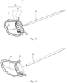
- Fig. 10 is structural schematic diagram of the left atrial appendage occlusion device according to embodiment 2 of the present application.
- Fig. 11 is another structural schematic diagram of the left atrial appendage occlusion device according to embodiment 2 of the present application.
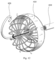
- Fig. 12 is yet another structural schematic diagram of the left atrial appendage occlusion device according to embodiment 2 of the present application. As shown in Fig. 10 to Fig.
- the left atrial appendage occluder 400 includes an occlusion member 410 and a guiding member 420.
- the guiding member 420 is located within the occlusion member 410 and is removable from the occlusion member 410, while the proximal end of the guiding member 420 protrudes out of the proximal end of the occlusion member 410.
- the left atrial appendage occlusion device 500 includes the occlusion member 410, the guiding member 420 and the push member 430. A distal end of the push member 430 is detachably connected to the proximal end of the occlusion member 410.
- the guiding member 420 is located within the occlusion member 410 and push member 430 and is removable from the occlusion member 410 and push member 430.
- the proximal end of the guiding member 420 protrudes out of the proximal end of the push member 430.
- the left atrial appendage occlusion system includes a delivery catheter and the left atrial appendage occlusion device 500.
- the delivery catheter is configured to establish a delivery channel
- the push member 430 is configured to push the occlusion member 410 along the delivery channel.
- the guiding member 420 is configured, after the push member 430 has been detached from the occlusion member 410, to guide the push member 430 when the push member 430 is needed to be connected to the occlusion member 410 again.
- This embodiment differs from embodiment 1 in that, the frame of the occlusion member in embodiment 1 has an umbrella shape (the distal end is open) and the occlusion member thus has an umbrella shape, while the frame of the occlusion member in this embodiment has a cage shape (the distal end is closed) frame and the occlusion member thus has a cage shape.
- the occlusion member 410 includes a frame 411, a polymer membrane 412 covering the frame 411 and anchors 413 fixed onto the frame 411. An elastic opening is formed in the polymer membrane 412.
- the frame 411 specifically includes a first fixing part (not shown), a second fixing part (not shown) and a plurality of frame strips connected to the first fixing part and the second fixing part.
- the first fixing part is located at the proximal end of the frame 411 and the second fixing part is located at the distal end of the frame 411.
- each of the first fixing part and the second fixing part is a hollow tube.
- the opening of the fixing part may be covered by the polymer membrane 412 and the elastic opening is formed here by the polymer membrane 412, which can not only facilitate the passage of the guiding member 420 but also ensure a good occlusion effect.
- the first fixing part is preferably provided with a connecting structure, such as the thread or spline structure, to facilitate the detachable connection with the push member 430.
- the left atrial appendage occluder 600 includes an occlusion member 610 and a guiding member 620.
- the guiding member 620 is located within the occlusion member 610 and is removable from the occlusion member 610, while the proximal end of the guiding member 620 protrudes out of the proximal end of the occlusion member 610.
- the left atrial appendage occlusion device 700 includes the occlusion member 610, the guiding member 620 and a push member 630.
- a distal end of the push member 630 is detachably connected to the proximal end of the occlusion member 610.
- the guiding member 620 is located within the occlusion member 610 and push member 630 and is removable from the occlusion member 610 and push member 630.
- the proximal end of the guiding member 620 protrudes out of the proximal end of the push member 630.
- the left atrial appendage occlusion system includes a delivery catheter 800 and the left atrial appendage occlusion device 700.
- the delivery catheter is configured to establish a delivery channel
- the push member 630 is configured to push the occlusion member 610 along the delivery channel.
- the guiding member 620 is configured to, after the push member 630 has been detached from the occlusion member 610, guide the push member 630 when the push member 630 is needed to be connected to the occlusion member 610 again.
- Embodiment 1 differs from Embodiment 1 in that, the occlusion member of Embodiment 1 comprises one frame, on which each of the polymer membrane and anchors is disposed, and is able to achieve the occlusion of the left atrial appendage as well as the fixation to the left atrial appendage, while the occlusion member in this embodiment includes two frames: a first frame and a second frame.
- the occlusion member 610 includes a frame 611, a polymer membrane covering the frame 611 and anchors 613 fixed onto the frame 611. An elastic opening is formed in the polymer membrane.
- the frame 611 includes a first frame 6110 and a second frame 6111.
- the first frame 6110 and a second frame 6111 are connected by the connector 6112.
- the first frame 6110 is located at the proximal end of the connector 6112, while the second frame 6111 is located at the distal end of the connector 6112.
- the polymer membrane covers the first frame 6110, and the anchors 613 are fixed on the second frame 6111.
- the first frame 6110 and the connector 6112 may be integrally formed, or may be connected by a thread structure or the like.
- the second frame 6111 and the connector 6112 may be integrally formed, or may be connected by a thread structure or the like.
- occlusion of left atrial appendage can be effected by the first frame 6110 and the polymer membrane covering the first frame 6110, and the fixation of the occlusion member 610 on the left atrial appendage can be effected by the second frame 6111 and the anchors 613 fixed on the frame 6111.
- the polymer membrane may also cover the second frame 6111, which makes the occlusion of left atrial appendage can also be effected by the second frame 6111 and the polymer membrane covering the second frame 6111, thereby achieving a better left atrial appendage occlusion effect.
- each of the first frame 6110 and the second frame 6111 has a cage shape, but in other embodiments, each of them may have an umbrella shape; or the first frame 6110 may have a cage shape while the second frame 6111 may have an umbrella shape; or the like.
- the first frame 6110 specifically includes a first fixing part (not shown), a second fixing part (not shown) and a plurality of frame strips connected to the first fixing part and the second fixing part.
- the first fixing part is located at the proximal end of the first frame 6110 and the second fixing part is located at the distal end of the first frame 6110.
- each of the first fixing part and the second fixing part is a hollow tube.
- the opening of the first fixing part may be covered by the polymer membrane and the elastic opening is formed here by the polymer membrane, which can not only facilitate the passage of the guiding member 620 but also ensure a good occlusion effect.
- the first fixing part is preferably provided with a connecting structure, such as the thread or spline structure, to facilitate the connection with the push member 630.
- the second fixing part may also be provided with a connecting structure, such as the thread or spline structure, to facilitate the connection with the connector 6112.
- the second frame 6111 specifically includes a third fixing part (not shown), a fourth fixing part (not shown) and a plurality of frame strips connected to the third fixing part and the fourth fixing part.
- the third fixing part is located at the proximal end of the second frame 6111 and the fourth fixing part is located at the distal end of the second frame 6111.
- each of the third fixing part and the fourth fixing part may be a hollow tube.
- the third fixing part may be provided with a connecting structure, such as the thread or spline structure, to facilitate the connection with the connector 6112.
- the guiding member is able to guide the push member to allow an easy reconnection between the occlusion member and push member for repositioning when the push member is needed to be connected to the occlusion member again.
Landscapes
- Health & Medical Sciences (AREA)
- Life Sciences & Earth Sciences (AREA)
- Surgery (AREA)
- Animal Behavior & Ethology (AREA)
- Veterinary Medicine (AREA)
- Vascular Medicine (AREA)
- Public Health (AREA)
- Engineering & Computer Science (AREA)
- Biomedical Technology (AREA)
- Heart & Thoracic Surgery (AREA)
- General Health & Medical Sciences (AREA)
- Molecular Biology (AREA)
- Medical Informatics (AREA)
- Nuclear Medicine, Radiotherapy & Molecular Imaging (AREA)
- Reproductive Health (AREA)
- Cardiology (AREA)
- Gastroenterology & Hepatology (AREA)
- Pulmonology (AREA)
- Oral & Maxillofacial Surgery (AREA)
- Transplantation (AREA)
- Surgical Instruments (AREA)
Description
- The present application relates to the field of medical instruments and, in particular, to a left atrial appendage occluder and a left atrial appendage occlusion device.
- Atrial Fibrillation (AF) is the common continuous arrhythmia in clinic. The incidence of AF in the general population is 0.5-1.3%. The main hazard of AF is to promote thrombosis. Complications such as stroke and peripheral vascular embolization caused by thrombus detachment significantly increase the disability and fatality rate. Stroke is the most common and devastating complication of AF. About 15 million people worldwide suffer from stroke each year, 20-25% of which are attributed to AF. The study suggests that 60% of patients with rheumatic heart disease have a cardiogenic thrombus from the left atrial appendage, and more than 90% of thrombi in the patients with non-valvular AF are formed in the left atrial appendage. Therefore, the intervention of the left atrial appendage to prevent thromboembolism in patients with AF, especially stroke, has important theoretical and clinical significance.
- Anticoagulant therapy is a standard method for preventing complications of stroke and AF at present, but has certain limitations. Therefore, the use of safer and more effective measures to prevent AF and stroke is of great significance. At present, medical interventions are mostly used to occlude the left atrial appendage. The commonly used left atrial appendage occluders comprise a single plug type occluder represented by WATCHMAN and a plug-and-disc type left atrial appendage occluder represented by AMPLATZER Cardiac Plug (ACP).
- The plug type left atrial appendage occluder has a nickel-titanium alloy frame with a self-expanding structure and barbs fixed around. The surface of the occluder towards atrial is covered with a porous polytetrafluoroethylene membrane for blood inflow outflow in the left atrial appendage.
- When the plug type left atrial appendage occluder has been plugged into the left atrial appendage, the entrance of left atrial appendage cannot be completely occluded since the shape of the entrance of the left atrial appendage is irregular, and the occluder has a limited deformability. Therefore, it is difficult to eliminate the thrombus caused by leakage of the left atrial appendage due to AF. The left atrial appendage has different structures and depths, and in addition, a multi-cavity structure. The plug type occluder is unable to fully adapt to the anatomical structures of all left atrial appendages as well as to achieve a stable fixation.
- The plug-and-disc type left atrial appendage occluder is a two-disc type device consisting of a butterfly blade which would be placed in the left atrial appendage and a butterfly cap. The butterfly blade and the butterfly cap are connected by a concave waist. The butterfly blade is placed in the left atrial appendage to prevent the occluder from shifting. The butterfly cap seals the entrance of the left atrial appendage.
- The plug-and-disc type left atrial appendage occluder has a structure in which the sealing disc and the fixed disc are integrated, and cannot be completely deformed independently. After the plug is plugged into the left atrial appendage, the disc portion adhered to the entrance of the left atrial appendage is subjected to the pull of the plug portion, so that the disc portion cannot fully fit to the entrance of the left atrial appendage, and thus it is difficult to achieve an optimal occluding effect. Moreover, since the length adjustments of the plug portion and the disc portion are limited, it is difficult to achieve the optimal fixation and blood flow blockage, and the disc structure does not adapt to different lumen shapes of the left atrial appendage.
-
WO02/071977A2 -
US2017/042549A1 discloses a left atrial appendage occlusion device comprising at least one deployable tissue anchor that is configured to deploy from a constrained configuration to a deployed configuration and retractable from the deployed configuration to a retracted configuration within the body. -
US2017/156840A1 discloses a medical device includes an occluder portion having an occluder eyelet and an anchor portion having an anchor eyelet, the anchor eyelet hingeably coupled to the occluder eyelet to make the anchor portion capable of moving between a retracted position and a deployed position upon the occluder portion being in an expanded position. -
CN101460102A also discloses an implantable device for the left atrium of a heart, wherein at least the one portion in the secondary form has a first part facing outwardly away from the other portion and a second part which deploys first from the primary form into the secondary form and which is folded back in a direction towards the other portion on to the first part. - In short, no matter the plug type left atrial appendage occluder or the plug-and-disc type left atrial appendage occluder, once separated from the delivery system, it will be impossible for the left atrial appendage occluder to be again engaged with the delivery system for positional adjustments, if an undesired position of the left atrial appendage occluder or a leakage of occlusion is founded. This would bring a great trouble to the operator's subsequent operations.
- It is an object of the present application to provide a left atrial appendage occluder and left atrial appendage occlusion device to solve the problem existed in the prior art that, once separated from the delivery system, it will be impossible for the left atrial appendage occluder to be again engaged with the delivery system for positional adjustments, if an undesired position of the left atrial appendage occluder or an leakage of occlusion is founded.
- To solve the above technical problem, the application provides a left atrial appendage occluder according to claim 1.
- Optionally, in the left atrial appendage occluder, the distal end of the guiding member is a blunt end.
- Optionally, in the left atrial appendage occluder, the guiding member is a guide wire having a ball head or a hook at the distal end thereof.
- Optionally, in the left atrial appendage occluder, the occlusion member comprises a frame, a polymer membrane covering the frame and anchors fixed on the frame, and the elastic opening is formed by means of the polymer membrane.
- Optionally, in the left atrial appendage occluder, the polymer membrane comprises a plurality of membrane sheets and interstices between the plurality of membrane sheets form the elastic opening, or the polymer membrane comprises a plurality of interlaced membrane wires and interstices between the plurality of interlaced membrane wires form the elastic opening.
- The present application also provides a left atrial appendage occlusion device according to claim 7.
- Optionally, in the left atrial appendage occlusion device, the guiding member is a guide wire having a blunt end at a distal end thereof.
- Optionally, in the left atrial appendage occlusion device, the occlusion member has an elastic opening, and the guiding member passes through the elastic opening and is removable out from the elastic opening. The elastic opening contracts upon removal of the guiding member from the elastic opening.
- Optionally, in the left atrial appendage occlusion device, the occlusion member comprises a frame, a polymer membrane covering the frame and anchors fixed on the frame, and the elastic opening is formed by means of the polymer membrane.
- Optionally, in the left atrial appendage occlusion device, the polymer membrane comprises a plurality of membrane sheets and interstices between the plurality of membrane sheets form the elastic opening, or the polymer membrane comprises a plurality of interlaced membrane wires and interstices between the plurality of interlaced membrane wires form the elastic opening.
- In the left atrial appendage occluder and left atrial appendage occlusion device provided in the present application, after the push member is separated from the occlusion member, the guiding member is able to guide the push member to allow an easy reconnection between the occlusion member and push member for repositioning, when the push member is needed to be connected to the occlusion member again.
-
-
Fig. 1 schematically illustrates a status of the left atrial appendage occlusion device according to embodiment 1 of the present application. -
Fig. 2 schematically illustrates another status of the left atrial appendage occlusion device according to embodiment 1 of the present application. -
Fig. 3 is a structural schematic diagram of the left atrial appendage occluder according to embodiment 1 of the present application. -
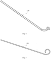
Fig. 4 is a structural schematic diagram of the guiding member according to embodiment 1 of the present application. -
Fig. 5 is another structural schematic diagram of the guiding member according to embodiment 1 of the present application. -
Fig. 6 is a structural schematic diagram of the elastic opening according to embodiment 1 of the present application. -
Fig. 7 is another structural schematic diagram of the elastic opening according to embodiment 1 of the present application. -
Fig. 8 is a schematic diagram showing the release of the occlusion member according to embodiment 1 of the present application. -
Fig. 9 is another schematic diagram showing the release of the occlusion member according to embodiment 1 of the present application. -
Fig. 10 is a structural schematic diagram of the left atrial appendage occlusion device according to embodiment 2 of the present application. -
Fig. 11 is another structural schematic diagram of the left atrial appendage occlusion device according to embodiment 2 of the present application. -
Fig. 12 is yet another structural schematic diagram of the left atrial appendage occlusion device according to embodiment 2 of the present application. -
Fig. 13 is a structural schematic diagram of the left atrial appendage occlusion system according to embodiment 3 of the present application. - In the figures:
- 100, left atrial appendage occluder;
- 110, occlusion member;
- 111, frame;
- 112, polymer membrane;
- 1120, membrane sheet;
- 1121, membrane wire;
- 113, anchor;
- 120, guiding member;
- 130, push member;
- 140, elastic opening;
- 200, left atrial appendage occlusion device;
- 300, delivery catheter;
- 400, left atrial appendage occluder;
- 410, occlusion member;
- 411, frame;
- 412, polymer membrane;
- 413, anchor;
- 420, guiding member;
- 430, push member;
- 500, left atrial appendage occlusion device;
- 600, left atrial appendage occluder;
- 610, occlusion member;
- 611, frame;
- 6110, first frame;
- 6111, second frame;
- 6112, connector;
- 613, anchor;
- 620, guiding member;
- 630, push member;
- 700, left atrial appendage occlusion device; and
- 800, delivery catheter.
- The left atrial appendage occluder and left atrial appendage occlusion device provided in present application will be described below in further detail with reference to specific embodiments and accompanying drawings. Features and advantages of the application will be more apparent from the following detailed description and appended claims. It should be noted that the drawings are in a very simplified form and not necessarily presented to scale, for the only purpose to facilitate convenient and explicit description of embodiments of the present application. The structures shown in the accompanying drawings are often parts of the actual structures. In particular, the figures are sometimes drawn using different scales in order to give emphasis on different details.
- As used herein, "proximal end" or "distal end" refers to the relative orientation, relative position, or direction of elements or actions that are relative to each other from the perspective of an operator operating the device. Yet without wishing to be limiting in any sense, the "proximal end" generally refers to the end of the medical device close to the operator during its normal operation, while the "distal end" generally refers to the end that enters into the body of the patient first.
- The core idea of this application is to provide a left atrial appendage occluder, a left atrial appendage occlusion device and a left atrial appendage occlusion system. The left atrial appendage occluder includes an occlusion member and a guiding member, and the guiding member is located within the occlusion member and is removable out from the occlusion member. The proximal end of the guiding member protrudes out of the proximal end of the occlusion member. The left atrial appendage occlusion device includes the occlusion member, the guiding member and the push member. A distal end of the push member is detachably connected to the proximal end of the occlusion member. The guiding member is located within the occlusion member and push member and is removable from the occlusion member and push member. The proximal end of the guiding member protrudes out of the proximal end of the push member. The left atrial appendage occlusion system includes a delivery catheter and a left atrial appendage occlusion device. The delivery catheter is configured to establish a delivery channel, and the push member is configured to push the occlusion member along the delivery channel. The guiding member is configured, after the push member has been detached from the occlusion member, to guide the push member when the push member is needed to be connected to the occlusion member again. In present application, after the push member has been detached from the occlusion member, the guiding member is able to guide the push member to allow an easy reconnection between the occlusion member and push member for repositioning, when the push member is needed to be connected to the occlusion member again.
- Reference is now made to
Fig. 1 to Fig. 3 .Fig. 1 schematically illustrates a status of the left atrial appendage occlusion device according to embodiment 1 of the present application.Fig. 2 schematically illustrates another status of the left atrial appendage occlusion device according to embodiment 1 of the present application.Fig. 3 is a structural schematic diagram of the left atrial appendage occluder according to embodiment 1 of the present application. As shown inFig. 1 to Fig. 3 , the leftatrial appendage occluder 100 includes anocclusion member 110 and a guidingmember 120. The guidingmember 120 is located within theocclusion member 110 and is removable from theocclusion member 110 while the proximal end of the guidingmember 120 protrudes out of the proximal end of theocclusion member 110. Due to the guidingmember 120, the above leftatrial appendage occluder 100 becomes a left atrial appendage occluder having a guiding function. After release of the left atrial appendage occluder 100 (more specifically, the occlusion member 110) by the push member, if the leftatrial appendage occluder 100 is found to be released to an undesired position, or a leakage of occlusion or other situations are occurred, the push member can be easily engaged with the left atrial appendage occluder 100 (more specifically, the occlusion member 110) again under the guide of the guidingmember 120, so that repositioning, withdrawal or another operations of the leftatrial appendage occluder 100 are able to be achieved. - With continued reference to
Figs. 1 to Fig. 3 , in this embodiment, the left atrialappendage occlusion device 200 includes anocclusion member 110, a guidingmember 120 and apush member 130. A distal end of thepush member 130 is detachably connected to the proximal end of theocclusion member 110. The guidingmember 120 is located within theocclusion member 110 and pushmember 130 and is removable from theocclusion member 110 and pushmember 130. The proximal end of the guidingmember 120 protrudes out of the proximal end of thepush member 130. - Specifically, the connection between the distal end of the
push member 130 and the proximal end of theocclusion member 110 may be accomplished by one of the thread connection, a snap-fit connection, spline connection and plug-pin connection. For example, the distal end of thepush member 130 is provided with an external thread and the proximal end of theocclusion member 110 is provided with an internal thread. Through fit of the external thread and the internal thread, thepush member 130 is able to be detachably connected to theocclusion member 110. As another example, the distal end of thepush member 130 is provided with an external spline and the proximal end of theocclusion member 110 is provided with an internal spline. Through fit of the external spline and the internal spline, thepush member 130 is able to be detachably connected to theocclusion member 110. - In this embodiment, the guiding
member 120 is a guide wire, which may be made of metal. A distal end of the guidingmember 120 may be located either inside or protrude out of theocclusion member 110. Preferably, the distal end of the guidingmember 120 protrudes out of the distal end of theocclusion member 110. In this case, the guidingmember 120 can facilitate positioning of theocclusion member 110 during release of theocclusion member 110, so that theocclusion member 110 can be easily deployed at a suitable position. - Further, the distal end of the guiding
member 120 is blunt (i.e., not sharp). In this way, when helping in positioning of theocclusion member 110 during its release, the guidingmember 120 will not cause damages to the surrounding tissues, such as the left atrial appendage, thereby ensuring reliability of the leftatrial appendage occluder 100 and left atrialappendage occlusion device 200. - In particular, reference is now made to
Fig. 4 , structural schematic diagram of the guiding member according to embodiment 1 of the present application, and toFig. 5 , another structural schematic diagram of the guiding member according to embodiment 1 of the present application. As shown inFig. 4 , the distal end of the guidingmember 120 may be a ball head or a body having an irregular cambered surface. In this way, the distal end of the guidingmember 120 presents a cambered surface, which will not cause damages to the surrounding tissues. Besides, as shown inFig. 5 , the distal end of the guidingmember 120 may also be a hook, so that no damages would be caused to the surrounding tissues. In another embodiment, the distal end of the guidingmember 120 may be flexible. - With continued reference to
Fig. 3 , in this embodiment, theocclusion member 110 has anelastic opening 140, through which the guidingmember 120 is passed. In addition, the guidingmember 120 is removable from theelastic opening 140, and theelastic opening 140 contracts upon removal of the guidingmember 120 from theelastic opening 140. Preferably, theelastic opening 140 will be closed after removal of the guidingmember 120 from theelastic opening 140. - Specifically, the
occlusion member 110 includes aframe 111, apolymer membrane 112 covering theframe 111 and anchors 113 fixed onto theframe 111. Theelastic opening 140 is formed by means of thepolymer membrane 112. Thepolymer membrane 112 may cover either an exterior or interior surface of theframe 111. Theanchors 113 may be hook-shaped and made of metal or degradable polymeric material. Theanchors 113 are fixed to the exterior surface of theframe 111. - The
frame 111 may be umbrella-shaped and made of metal or degradable polymeric material. Specifically, theframe 111 may include a fixing part (not shown) and a plurality of frame strips connected to the fixing part. The plurality of frame strips are uniformly distributed on the fixing part. There are many interstices inframe 111 for passing the guidingmember 120 therethrough. Further, the fixing part may be a hollow tube. Further, the opening of the hollow tube is covered by thepolymer membrane 112 and the elastic opening is formed here by thepolymer membrane 112, which can not only facilitate the passage of the guidingmember 120 but also ensure a good occlusion effect. In this embodiment, the fixing part is located at the proximal end of the frame 111 (or, the occlusion member 110). Preferably, the fixing part is provided with a connecting structure, such as the thread or spline structure, to facilitate the detachable connection with thepush member 130. - Reference is now made to
Fig. 6 , a structural schematic diagram of the elastic opening according to embodiment 1 of the present application, and toFig. 7 , another structural schematic diagram of the elastic opening according to embodiment 1 of the present application. As shown inFig. 6 , theelastic opening 140 may be formed as follows: thepolymer membrane 112 includes a plurality ofmembrane sheets 1120, and interstices between the plurality of membrane sheets form theelastic opening 140. When the guidingmember 120 is locating in the elastic opening shown inFig. 6 , themembrane sheets 1120 are squeezed and interstices between the plurality ofmembrane sheets 1120 are enlarged, thereby leading to a largeelastic opening 140. Upon removal of the guidingmember 120, themembrane sheets 1120 recover, and interstices between the plurality ofmembrane sheets 1120 contracts or closes, leading to a smallelastic opening 140. Therefore, this design not only facilitates the passage of the guidingmember 120 but also ensures a good occlusion effect. - Further, as shown in
Fig. 7 , theelastic opening 140 may also be implemented as follows : thepolymer membrane 112 comprises a plurality of interlacedmembrane wires 1121, and interstices between the plurality of interlacedmembrane wires 1121 forms theelastic opening 140. When the guidingmember 120 is locating in theelastic opening 140 shown inFig. 7 , themembrane wires 1121 are squeezed and interstices between the plurality of interlacedmembrane wires 1121 are enlarged, leading to a largeelastic opening 140. Upon removal of the guidingmember 120, themembrane wires 1121 recover, and interstices between the plurality of interlacedmembrane wires 1121 contracts or closes, leading to a smallelastic opening 140. Therefore, this design not only facilitates the passage of the guidingmember 120 but also ensures a good occlusion effect. - Accordingly, this embodiment also provides a left atrial appendage occlusion system. Referring to
Fig. 8 , the left atrial appendage occlusion system includes adelivery catheter 300 and the left atrialappendage occlusion device 200. Thedelivery catheter 300 is configured to establish a delivery channel, and thepush member 130 is configured to push theocclusion member 110 along the delivery channel. The guidingmember 120 is configured, after thepush member 130 has been detached from theocclusion member 110, to guide thepush member 130 when thepush member 130 is needed to be connected to theocclusion member 110 again. - With continued reference to
Fig. 8 and Fig. 9 , occlusion of the left atrial appendage by theocclusion member 110 is achievable as follows: thedelivery catheter 300 establishes a delivery channel and the guidingmember 120 helps in positioning the release position of theocclusion member 110. Theocclusion member 110 is pushed out of terminal of thedelivery catheter 300 by thepush member 130 and is released. At this time, theocclusion member 110 is plugged and tightly fitted into the left atrial appendage wall. After that, thepush member 130 is detached from theocclusion member 110. Further, thepush member 130 can be removable from thedelivery catheter 300, meanwhile thepush member 130 can also be separated from the guidingmember 120. If an unsatisfactory position of theocclusion member 110 or a leakage of the occlusion is found after the separation of thepush member 130 from theocclusion member 110, thepush member 130 can be sleeved outside the guidingmember 120 again and is reconnected to theocclusion member 110 along the guidingmember 120, so that theocclusion member 110 is able to be repositioned or withdrawn. Therefore, after thepush member 130 has been separated from theocclusion member 110, the guidingmember 120 is able to guide thepush member 130 when thepush member 130 is needed to be connected to theocclusion member 110 again, so as to allow an easy reconnection of thepush member 130 and theocclusion member 110 for repositioning. - Reference is now made to
Fig. 10 to Fig12 .Fig. 10 is structural schematic diagram of the left atrial appendage occlusion device according to embodiment 2 of the present application.Fig. 11 is another structural schematic diagram of the left atrial appendage occlusion device according to embodiment 2 of the present application.Fig. 12 is yet another structural schematic diagram of the left atrial appendage occlusion device according to embodiment 2 of the present application. As shown inFig. 10 to Fig. 12 , in this embodiment, the leftatrial appendage occluder 400 includes anocclusion member 410 and a guiding member 420.The guidingmember 420 is located within theocclusion member 410 and is removable from theocclusion member 410, while the proximal end of the guidingmember 420 protrudes out of the proximal end of theocclusion member 410. The left atrialappendage occlusion device 500 includes theocclusion member 410, the guidingmember 420 and thepush member 430. A distal end of thepush member 430 is detachably connected to the proximal end of theocclusion member 410. The guidingmember 420 is located within theocclusion member 410 and pushmember 430 and is removable from theocclusion member 410 and pushmember 430. The proximal end of the guidingmember 420 protrudes out of the proximal end of thepush member 430. The left atrial appendage occlusion system includes a delivery catheter and the left atrialappendage occlusion device 500. The delivery catheter is configured to establish a delivery channel, and thepush member 430 is configured to push theocclusion member 410 along the delivery channel. The guidingmember 420 is configured, after thepush member 430 has been detached from theocclusion member 410, to guide thepush member 430 when thepush member 430 is needed to be connected to theocclusion member 410 again. - This embodiment differs from embodiment 1 in that, the frame of the occlusion member in embodiment 1 has an umbrella shape (the distal end is open) and the occlusion member thus has an umbrella shape, while the frame of the occlusion member in this embodiment has a cage shape (the distal end is closed) frame and the occlusion member thus has a cage shape.
- Specifically, the
occlusion member 410 includes aframe 411, apolymer membrane 412 covering theframe 411 and anchors 413 fixed onto theframe 411. An elastic opening is formed in thepolymer membrane 412. - In this embodiment, the
frame 411 specifically includes a first fixing part (not shown), a second fixing part (not shown) and a plurality of frame strips connected to the first fixing part and the second fixing part. Here, the first fixing part is located at the proximal end of theframe 411 and the second fixing part is located at the distal end of theframe 411. There are many interstices inframe 411 for passing the guidingmember 420 therethrough. Specifically, each of the first fixing part and the second fixing part is a hollow tube. Further, the opening of the fixing part may be covered by thepolymer membrane 412 and the elastic opening is formed here by thepolymer membrane 412, which can not only facilitate the passage of the guidingmember 420 but also ensure a good occlusion effect. In this embodiment, the first fixing part is preferably provided with a connecting structure, such as the thread or spline structure, to facilitate the detachable connection with thepush member 430. - As to the guiding
member 420, elastic opening, delivery catheter and other components and the relationships between components in embodiment 2, reference can be made to embodiment 1 as appropriate, description of which is omitted hereto. - Reference is now made to
Fig. 13 , structural schematic diagram of the left atrial appendage occlusion system according to embodiment 3 of the present application. As shown inFig. 13 , in this embodiment, the leftatrial appendage occluder 600 includes anocclusion member 610 and a guidingmember 620. The guidingmember 620 is located within theocclusion member 610 and is removable from theocclusion member 610, while the proximal end of the guidingmember 620 protrudes out of the proximal end of theocclusion member 610. The left atrialappendage occlusion device 700 includes theocclusion member 610, the guidingmember 620 and apush member 630. A distal end of thepush member 630 is detachably connected to the proximal end of theocclusion member 610. The guidingmember 620 is located within theocclusion member 610 and pushmember 630 and is removable from theocclusion member 610 and pushmember 630. The proximal end of the guidingmember 620 protrudes out of the proximal end of thepush member 630. The left atrial appendage occlusion system includes adelivery catheter 800 and the left atrialappendage occlusion device 700. The delivery catheter is configured to establish a delivery channel, and thepush member 630 is configured to push theocclusion member 610 along the delivery channel. The guidingmember 620 is configured to, after thepush member 630 has been detached from theocclusion member 610, guide thepush member 630 when thepush member 630 is needed to be connected to theocclusion member 610 again. - This embodiment differs from Embodiment 1 in that, the occlusion member of Embodiment 1 comprises one frame, on which each of the polymer membrane and anchors is disposed, and is able to achieve the occlusion of the left atrial appendage as well as the fixation to the left atrial appendage, while the occlusion member in this embodiment includes two frames: a first frame and a second frame.
- Specifically, the
occlusion member 610 includes aframe 611, a polymer membrane covering theframe 611 and anchors 613 fixed onto theframe 611. An elastic opening is formed in the polymer membrane. - Further, the
frame 611 includes afirst frame 6110 and asecond frame 6111. Thefirst frame 6110 and asecond frame 6111 are connected by theconnector 6112. Thefirst frame 6110 is located at the proximal end of theconnector 6112, while thesecond frame 6111 is located at the distal end of theconnector 6112. The polymer membrane covers thefirst frame 6110, and theanchors 613 are fixed on thesecond frame 6111. Thefirst frame 6110 and theconnector 6112 may be integrally formed, or may be connected by a thread structure or the like. Similarly, thesecond frame 6111 and theconnector 6112 may be integrally formed, or may be connected by a thread structure or the like. That is, in this embodiment, occlusion of left atrial appendage can be effected by thefirst frame 6110 and the polymer membrane covering thefirst frame 6110, and the fixation of theocclusion member 610 on the left atrial appendage can be effected by thesecond frame 6111 and theanchors 613 fixed on theframe 6111. Preferably, the polymer membrane may also cover thesecond frame 6111, which makes the occlusion of left atrial appendage can also be effected by thesecond frame 6111 and the polymer membrane covering thesecond frame 6111, thereby achieving a better left atrial appendage occlusion effect. - In this embodiment, each of the
first frame 6110 and thesecond frame 6111 has a cage shape, but in other embodiments, each of them may have an umbrella shape; or thefirst frame 6110 may have a cage shape while thesecond frame 6111 may have an umbrella shape; or the like. - In this embodiment, the
first frame 6110 specifically includes a first fixing part (not shown), a second fixing part (not shown) and a plurality of frame strips connected to the first fixing part and the second fixing part. Here, the first fixing part is located at the proximal end of thefirst frame 6110 and the second fixing part is located at the distal end of thefirst frame 6110. There are many interstices infirst frame 6110 for passing the guidingmember 620 therethrough. Specifically, each of the first fixing part and the second fixing part is a hollow tube. Further, the opening of the first fixing part may be covered by the polymer membrane and the elastic opening is formed here by the polymer membrane, which can not only facilitate the passage of the guidingmember 620 but also ensure a good occlusion effect. In this embodiment, the first fixing part is preferably provided with a connecting structure, such as the thread or spline structure, to facilitate the connection with thepush member 630. Further, the second fixing part may also be provided with a connecting structure, such as the thread or spline structure, to facilitate the connection with theconnector 6112. - In this embodiment, the
second frame 6111 specifically includes a third fixing part (not shown), a fourth fixing part (not shown) and a plurality of frame strips connected to the third fixing part and the fourth fixing part. Here, the third fixing part is located at the proximal end of thesecond frame 6111 and the fourth fixing part is located at the distal end of thesecond frame 6111. There are many interstices insecond frame 6111 for passing the guidingmember 620 therethrough. Specifically, each of the third fixing part and the fourth fixing part may be a hollow tube. Further, the third fixing part may be provided with a connecting structure, such as the thread or spline structure, to facilitate the connection with theconnector 6112. - In summary, in the left atrial appendage occluder, left atrial appendage occlusion device and left atrial appendage occlusion system provided in present application, after the push member is separated from the occlusion member, the guiding member is able to guide the push member to allow an easy reconnection between the occlusion member and push member for repositioning when the push member is needed to be connected to the occlusion member again.
- The description presented above is merely a few preferred embodiments of the present application and does not limit the scope of the present application in any sense.
Claims (9)
- A left atrial appendage occluder (100, 400, 600), comprising an occlusion member (110, 410, 610) and a guiding member (120, 420, 620), wherein the guiding member (120, 420, 620) is configured to position a push member (130, 430, 630) to the occlusion member (110, 410, 610), wherein the guiding member (120, 420, 620) is located within the occlusion member (110, 410, 610) and removable from the occlusion member (110, 410, 610), and wherein a proximal end of the guiding member (120, 420, 620) protrudes out of a proximal end of the occlusion member (110, 410, 610), wherein a distal end of the guiding member (120, 420, 620) protrudes out of a distal end of the occlusion member (110, 410, 610), characterized in that, the occlusion member (110, 410, 610) has an elastic opening (140), through which the guiding member (120, 420, 620) is passed, and wherein the elastic opening (140) contracts upon a removal of the guiding member (120, 420, 620) from the elastic opening (140).
- The left atrial appendage occluder (100, 400, 600) of claim 1, wherein the distal end of the guiding member (120, 420, 620) is a blunt end.
- The left atrial appendage occluder (100, 400, 600) of claim 2, wherein the guiding member (120, 420, 620) is a guide wire having a ball head or a hook at a distal end thereof.
- The left atrial appendage occluder (100, 400, 600) of claim 1, wherein the occlusion member (110, 410, 610) comprises a frame (111, 411, 611), a polymer membrane (112, 412) covering the frame (111, 411, 611) and anchors (113, 413, 613) fixed on the frame (111, 411, 611), and wherein the elastic opening (140) is formed by means of the polymer membrane (112, 412).
- The left atrial appendage occluder (100, 400, 600) of claim 4, wherein the polymer membrane (112, 412) comprises a plurality of membrane sheets (1120), and interstices between the plurality of membrane sheets (1120) form the elastic opening (140), or wherein the polymer membrane (112, 412) comprises a plurality of interlaced membrane wires (1121), and interstices between the plurality of interlaced membrane wires (1121) form the elastic opening (140).
- A left atrial appendage occlusion device (200, 500, 700), characterized in that, it comprises the left atrial appendage occluder (100, 400, 600) as claimed in any one of claims 1-5, and a push member (130, 430, 630), a distal end of the push member (130, 430, 630) detachably connected to the proximal end of the occlusion member (110, 410, 610), wherein the guiding member (120, 420, 620) is configured to position the push member (130, 430, 630) to the occlusion member (110, 410, 610), wherein the guiding member (120, 420, 620) is located within the occlusion member (110, 410, 610) and push member (130, 430, 630) and movable from the occlusion member (110, 410, 610) and the push member (130, 430, 630), and wherein a proximal end of the guiding member (120, 420, 620) protrudes out of a proximal end of the push member (130, 430, 630).
- The left atrial appendage occlusion device (200, 500, 700) of claim 6, wherein the guiding member (120, 420, 620) is a guide wire having a blunt end at a distal end thereof.
- The left atrial appendage occlusion device (200, 500, 700) of claim 6, when not dependent on claim 4, wherein the occlusion member (110, 410, 610) comprises a frame (111, 411, 611), a polymer membrane (112, 412) covering the frame (111, 411, 611) and anchors (113, 413, 613) fixed on the frame (111, 411, 611), and wherein the elastic opening (140) is formed by means of the polymer membrane (112, 412).
- The left atrial appendage occlusion device (200, 500, 700) of claim 8, wherein the polymer membrane (112, 412) comprises a plurality of membrane sheets (1120), and interstices between the plurality of membrane sheets (1120) form the elastic opening (140), or wherein the polymer membrane (112, 412) comprises a plurality of interlaced membrane wires (1121), and interstices between the plurality of interlaced membrane wires (1121) form the elastic opening (140).
Applications Claiming Priority (2)
| Application Number | Priority Date | Filing Date | Title |
|---|---|---|---|
| CN201710910822.7A CN109567891A (en) | 2017-09-29 | 2017-09-29 | Occluder for left auricle and left atrial appendage occlusion device |
| PCT/CN2018/101972 WO2019062403A1 (en) | 2017-09-29 | 2018-08-23 | Left atrial appendage occluder and left atrial appendage occlusion device |
Publications (4)
| Publication Number | Publication Date |
|---|---|
| EP3689271A1 EP3689271A1 (en) | 2020-08-05 |
| EP3689271A4 EP3689271A4 (en) | 2021-01-20 |
| EP3689271B1 true EP3689271B1 (en) | 2025-05-14 |
| EP3689271C0 EP3689271C0 (en) | 2025-05-14 |
Family
ID=65900556
Family Applications (1)
| Application Number | Title | Priority Date | Filing Date |
|---|---|---|---|
| EP18860656.0A Active EP3689271B1 (en) | 2017-09-29 | 2018-08-23 | Left atrial appendage occluder and left atrial appendage occlusion device |
Country Status (3)
| Country | Link |
|---|---|
| EP (1) | EP3689271B1 (en) |
| CN (1) | CN109567891A (en) |
| WO (1) | WO2019062403A1 (en) |
Families Citing this family (13)
| Publication number | Priority date | Publication date | Assignee | Title |
|---|---|---|---|---|
| CN116549030B (en) * | 2019-12-20 | 2026-03-17 | 先健科技(深圳)有限公司 | Occlusion devices and occlusion systems |
| CN112998796B (en) * | 2019-12-20 | 2023-01-03 | 先健科技(深圳)有限公司 | Conveying device |
| CN112998771B (en) * | 2019-12-20 | 2023-05-02 | 先健科技(深圳)有限公司 | Plugging system |
| US11992221B2 (en) | 2019-12-20 | 2024-05-28 | Lifetech Scientific (Shenzhen) Co., Ltd. | Occluder, occluding system and conveying device |
| CN113116407B (en) * | 2019-12-31 | 2023-05-02 | 先健科技(深圳)有限公司 | Plugging device |
| CN113116409B (en) * | 2019-12-31 | 2022-12-20 | 先健科技(深圳)有限公司 | Plugging device and plugging device conveying system |
| WO2022042717A1 (en) * | 2020-08-31 | 2022-03-03 | 杭州德诺电生理医疗科技有限公司 | Left atrial appendage occluder |
| CN114191003A (en) * | 2020-08-31 | 2022-03-18 | 杭州德诺电生理医疗科技有限公司 | Left auricle plugging device |
| CN112206029B (en) * | 2020-10-28 | 2025-10-28 | 上海佐心医疗科技有限公司 | Medical systems and medical devices |
| CN114642467B (en) * | 2020-12-17 | 2024-12-31 | 先健科技(深圳)有限公司 | Occluder and occlusion system |
| CN114642469B (en) * | 2020-12-21 | 2026-01-20 | 杭州德诺电生理医疗科技有限公司 | Left atrial appendage ablation device and control method |
| CN112674829B (en) * | 2020-12-22 | 2022-03-18 | 南京吉米医疗科技有限公司 | Left auricle plugging device and plugging method thereof |
| CN117338365B (en) * | 2023-12-06 | 2024-03-08 | 东南大学泰州生物医药与医疗器械研究院 | Left auricle plugging device |
Family Cites Families (19)
| Publication number | Priority date | Publication date | Assignee | Title |
|---|---|---|---|---|
| DE29714242U1 (en) * | 1997-08-08 | 1998-12-10 | Applied Biometrics, Inc., Burnsville, Minnesota | Closure device for closing a physical anomaly such as vascular opening or opening in a septum |
| US7128073B1 (en) * | 1998-11-06 | 2006-10-31 | Ev3 Endovascular, Inc. | Method and device for left atrial appendage occlusion |
| CN1529571A (en) * | 2001-03-08 | 2004-09-15 | ̩ | Atrial Filter Implant |
| CN2626433Y (en) * | 2003-05-21 | 2004-07-21 | 卢才义 | Congenital heart disease plugging device with safe release device |
| CN101415379B (en) * | 2006-02-14 | 2012-06-20 | 萨德拉医学公司 | Systems for delivering medical implants |
| DE102006050385A1 (en) * | 2006-10-05 | 2008-04-10 | pfm Produkte für die Medizin AG | Implantable mechanism for use in human and/or animal body for e.g. closing atrium septum defect, has partial piece that is folded back on another partial piece from primary form into secondary form of carrying structure |
| CN201067447Y (en) * | 2007-07-13 | 2008-06-04 | 卢才义 | Congenital heart disease plugging device component with safety positioning and fast switching structure |
| EP2326261B1 (en) * | 2008-08-25 | 2018-12-05 | Cardiokinetix, Inc. | Retrievable cardiac devices |
| US10631969B2 (en) * | 2009-06-17 | 2020-04-28 | Coherex Medical, Inc. | Medical device for modification of left atrial appendage and related systems and methods |
| CN102258402B (en) * | 2010-05-25 | 2014-11-26 | 上海微创医疗器械(集团)有限公司 | Heart valve delivery system and delivery device |
| AU2012307020B2 (en) * | 2011-09-09 | 2015-04-30 | Endoluminal Sciences Pty Ltd | Means for controlled sealing of endovascular devices |
| EP2567663A1 (en) * | 2011-09-09 | 2013-03-13 | Occlutech Holding AG | A collapsible medical closing device, a method and a medical system for delivering an object |
| US9445797B2 (en) * | 2012-09-13 | 2016-09-20 | Medtronic, Inc. | Percutaneous atrial and ventricular septal defect closure device |
| US10039536B2 (en) * | 2012-11-16 | 2018-08-07 | W. L. Gore & Associates, Inc. | Implantable medical device deployment system |
| US10617425B2 (en) * | 2014-03-10 | 2020-04-14 | Conformal Medical, Inc. | Devices and methods for excluding the left atrial appendage |
| CN203677143U (en) * | 2013-12-23 | 2014-07-02 | 上海形状记忆合金材料有限公司 | Push rod |
| CN204562476U (en) * | 2014-12-02 | 2015-08-19 | 先健科技(深圳)有限公司 | The conveyer device of implant and implanted medical device |
| US20170035433A1 (en) * | 2015-08-06 | 2017-02-09 | Thomas J. Forbes | Left atrial appendage occluder device anchoring system, anchor, and method of attachment |
| CN106580375B (en) * | 2016-12-15 | 2020-09-22 | 杭州启明医疗器械股份有限公司 | Seal wire regulator and conveying system control handle |
-
2017
- 2017-09-29 CN CN201710910822.7A patent/CN109567891A/en active Pending
-
2018
- 2018-08-23 WO PCT/CN2018/101972 patent/WO2019062403A1/en not_active Ceased
- 2018-08-23 EP EP18860656.0A patent/EP3689271B1/en active Active
Also Published As
| Publication number | Publication date |
|---|---|
| EP3689271A4 (en) | 2021-01-20 |
| EP3689271A1 (en) | 2020-08-05 |
| CN109567891A (en) | 2019-04-05 |
| WO2019062403A1 (en) | 2019-04-04 |
| EP3689271C0 (en) | 2025-05-14 |
Similar Documents
| Publication | Publication Date | Title |
|---|---|---|
| EP3689271A1 (en) | Left atrial appendage occluder and left atrial appendage occlusion device | |
| KR101681346B1 (en) | Heart occlusion devices | |
| US9332976B2 (en) | Tissue closure device | |
| US11883033B2 (en) | Left atrial appendage occluder, and method of application | |
| JP3712630B2 (en) | Septal defect closure device | |
| US8277480B2 (en) | Catch member for PFO occluder | |
| US10258343B2 (en) | Left atrial appendage occluder | |
| CA2581677C (en) | Occluder device double securement system for delivery/recovery of such occluder device | |
| CN105263425B (en) | Tissue ligation device and method thereof | |
| US8114123B2 (en) | Apparatus and methods for tissue gathering and securing | |
| CN106473791B (en) | Left auricle plugging device with adjustable distance | |
| CN209474705U (en) | Split type occluder for left auricle | |
| EP2716237A1 (en) | Left atrial appendage occluder | |
| EP2158847A1 (en) | Occluder delivery system | |
| US20040225324A1 (en) | Delivery system with safety tether | |
| EP1480565B1 (en) | Vascular occlusion device | |
| WO2020216207A1 (en) | Occluder support and preparation method therefor | |
| CN103857341A (en) | Heart occlusion devices | |
| US20090264920A1 (en) | Catheter-based septal occlusion device and adhesive delivery system | |
| CN113749719B (en) | Implant device with fishbone-shaped anchoring structure and delivery system thereof | |
| EP3698729A1 (en) | Left atrial appendage occlusion device and left atrial appendage occlusion system | |
| JP4951503B2 (en) | Defect closure device | |
| CN107303191B (en) | Left auricle occluder and manufacturing method thereof | |
| WO2022214110A1 (en) | Transapical surgery assistance system | |
| CN107198552B (en) | Left auricle plugging device |
Legal Events
| Date | Code | Title | Description |
|---|---|---|---|
| STAA | Information on the status of an ep patent application or granted ep patent |
Free format text: STATUS: THE INTERNATIONAL PUBLICATION HAS BEEN MADE |
|
| PUAI | Public reference made under article 153(3) epc to a published international application that has entered the european phase |
Free format text: ORIGINAL CODE: 0009012 |
|
| STAA | Information on the status of an ep patent application or granted ep patent |
Free format text: STATUS: REQUEST FOR EXAMINATION WAS MADE |
|
| 17P | Request for examination filed |
Effective date: 20200416 |
|
| AK | Designated contracting states |
Kind code of ref document: A1 Designated state(s): AL AT BE BG CH CY CZ DE DK EE ES FI FR GB GR HR HU IE IS IT LI LT LU LV MC MK MT NL NO PL PT RO RS SE SI SK SM TR |
|
| AX | Request for extension of the european patent |
Extension state: BA ME |
|
| DAV | Request for validation of the european patent (deleted) | ||
| DAX | Request for extension of the european patent (deleted) | ||
| A4 | Supplementary search report drawn up and despatched |
Effective date: 20201221 |
|
| RIC1 | Information provided on ipc code assigned before grant |
Ipc: A61B 17/12 20060101AFI20201215BHEP Ipc: A61B 17/22 20060101ALI20201215BHEP Ipc: A61F 2/06 20130101ALI20201215BHEP |
|
| RAP1 | Party data changed (applicant data changed or rights of an application transferred) |
Owner name: SHANGHAI MICROPORT CARDIOADVENT CO., LTD. |
|
| STAA | Information on the status of an ep patent application or granted ep patent |
Free format text: STATUS: EXAMINATION IS IN PROGRESS |
|
| 17Q | First examination report despatched |
Effective date: 20230322 |
|
| GRAP | Despatch of communication of intention to grant a patent |
Free format text: ORIGINAL CODE: EPIDOSNIGR1 |
|
| STAA | Information on the status of an ep patent application or granted ep patent |
Free format text: STATUS: GRANT OF PATENT IS INTENDED |
|
| INTG | Intention to grant announced |
Effective date: 20241220 |
|
| GRAS | Grant fee paid |
Free format text: ORIGINAL CODE: EPIDOSNIGR3 |
|
| GRAA | (expected) grant |
Free format text: ORIGINAL CODE: 0009210 |
|
| STAA | Information on the status of an ep patent application or granted ep patent |
Free format text: STATUS: THE PATENT HAS BEEN GRANTED |
|
| AK | Designated contracting states |
Kind code of ref document: B1 Designated state(s): AL AT BE BG CH CY CZ DE DK EE ES FI FR GB GR HR HU IE IS IT LI LT LU LV MC MK MT NL NO PL PT RO RS SE SI SK SM TR |
|
| REG | Reference to a national code |
Ref country code: GB Ref legal event code: FG4D |
|
| REG | Reference to a national code |
Ref country code: CH Ref legal event code: EP |
|
| REG | Reference to a national code |
Ref country code: IE Ref legal event code: FG4D |
|
| REG | Reference to a national code |
Ref country code: DE Ref legal event code: R096 Ref document number: 602018081997 Country of ref document: DE |
|
| U01 | Request for unitary effect filed |
Effective date: 20250605 |
|
| U07 | Unitary effect registered |
Designated state(s): AT BE BG DE DK EE FI FR IT LT LU LV MT NL PT RO SE SI Effective date: 20250613 |
|
| U20 | Renewal fee for the european patent with unitary effect paid |
Year of fee payment: 8 Effective date: 20250827 |
|
| PG25 | Lapsed in a contracting state [announced via postgrant information from national office to epo] |
Ref country code: ES Free format text: LAPSE BECAUSE OF FAILURE TO SUBMIT A TRANSLATION OF THE DESCRIPTION OR TO PAY THE FEE WITHIN THE PRESCRIBED TIME-LIMIT Effective date: 20250514 |
|
| PG25 | Lapsed in a contracting state [announced via postgrant information from national office to epo] |
Ref country code: NO Free format text: LAPSE BECAUSE OF FAILURE TO SUBMIT A TRANSLATION OF THE DESCRIPTION OR TO PAY THE FEE WITHIN THE PRESCRIBED TIME-LIMIT Effective date: 20250814 Ref country code: GR Free format text: LAPSE BECAUSE OF FAILURE TO SUBMIT A TRANSLATION OF THE DESCRIPTION OR TO PAY THE FEE WITHIN THE PRESCRIBED TIME-LIMIT Effective date: 20250815 |
|
| PG25 | Lapsed in a contracting state [announced via postgrant information from national office to epo] |
Ref country code: PL Free format text: LAPSE BECAUSE OF FAILURE TO SUBMIT A TRANSLATION OF THE DESCRIPTION OR TO PAY THE FEE WITHIN THE PRESCRIBED TIME-LIMIT Effective date: 20250514 |
|
| PGFP | Annual fee paid to national office [announced via postgrant information from national office to epo] |
Ref country code: GB Payment date: 20250820 Year of fee payment: 8 |
|
| PG25 | Lapsed in a contracting state [announced via postgrant information from national office to epo] |
Ref country code: HR Free format text: LAPSE BECAUSE OF FAILURE TO SUBMIT A TRANSLATION OF THE DESCRIPTION OR TO PAY THE FEE WITHIN THE PRESCRIBED TIME-LIMIT Effective date: 20250514 |
|
| PG25 | Lapsed in a contracting state [announced via postgrant information from national office to epo] |
Ref country code: RS Free format text: LAPSE BECAUSE OF FAILURE TO SUBMIT A TRANSLATION OF THE DESCRIPTION OR TO PAY THE FEE WITHIN THE PRESCRIBED TIME-LIMIT Effective date: 20250814 |
|
| PG25 | Lapsed in a contracting state [announced via postgrant information from national office to epo] |
Ref country code: IS Free format text: LAPSE BECAUSE OF FAILURE TO SUBMIT A TRANSLATION OF THE DESCRIPTION OR TO PAY THE FEE WITHIN THE PRESCRIBED TIME-LIMIT Effective date: 20250914 |
|
| PG25 | Lapsed in a contracting state [announced via postgrant information from national office to epo] |
Ref country code: SM Free format text: LAPSE BECAUSE OF FAILURE TO SUBMIT A TRANSLATION OF THE DESCRIPTION OR TO PAY THE FEE WITHIN THE PRESCRIBED TIME-LIMIT Effective date: 20250514 |
|
| PG25 | Lapsed in a contracting state [announced via postgrant information from national office to epo] |
Ref country code: CZ Free format text: LAPSE BECAUSE OF FAILURE TO SUBMIT A TRANSLATION OF THE DESCRIPTION OR TO PAY THE FEE WITHIN THE PRESCRIBED TIME-LIMIT Effective date: 20250514 |
|
| PG25 | Lapsed in a contracting state [announced via postgrant information from national office to epo] |
Ref country code: SK Free format text: LAPSE BECAUSE OF FAILURE TO SUBMIT A TRANSLATION OF THE DESCRIPTION OR TO PAY THE FEE WITHIN THE PRESCRIBED TIME-LIMIT Effective date: 20250514 |
|
| PLBE | No opposition filed within time limit |
Free format text: ORIGINAL CODE: 0009261 |
|
| STAA | Information on the status of an ep patent application or granted ep patent |
Free format text: STATUS: NO OPPOSITION FILED WITHIN TIME LIMIT |
|
| REG | Reference to a national code |
Ref country code: CH Ref legal event code: H13 Free format text: ST27 STATUS EVENT CODE: U-0-0-H10-H13 (AS PROVIDED BY THE NATIONAL OFFICE) Effective date: 20260324 |
|
| REG | Reference to a national code |
Ref country code: CH Ref legal event code: L10 Free format text: ST27 STATUS EVENT CODE: U-0-0-L10-L00 (AS PROVIDED BY THE NATIONAL OFFICE) Effective date: 20260325 |
|
| PG25 | Lapsed in a contracting state [announced via postgrant information from national office to epo] |
Ref country code: MC Free format text: LAPSE BECAUSE OF FAILURE TO SUBMIT A TRANSLATION OF THE DESCRIPTION OR TO PAY THE FEE WITHIN THE PRESCRIBED TIME-LIMIT Effective date: 20250514 |
|
| 26N | No opposition filed |
Effective date: 20260217 |
|
| PG25 | Lapsed in a contracting state [announced via postgrant information from national office to epo] |
Ref country code: CH Free format text: LAPSE BECAUSE OF NON-PAYMENT OF DUE FEES Effective date: 20250831 |