EP3688310B1 - A slide valve for a twin-screw compressor - Google Patents
A slide valve for a twin-screw compressor Download PDFInfo
- Publication number
- EP3688310B1 EP3688310B1 EP18786410.3A EP18786410A EP3688310B1 EP 3688310 B1 EP3688310 B1 EP 3688310B1 EP 18786410 A EP18786410 A EP 18786410A EP 3688310 B1 EP3688310 B1 EP 3688310B1
- Authority
- EP
- European Patent Office
- Prior art keywords
- slide valve
- free end
- twin
- cavity
- screw compressor
- Prior art date
- Legal status (The legal status is an assumption and is not a legal conclusion. Google has not performed a legal analysis and makes no representation as to the accuracy of the status listed.)
- Active
Links
Images



Classifications
-
- F—MECHANICAL ENGINEERING; LIGHTING; HEATING; WEAPONS; BLASTING
- F04—POSITIVE - DISPLACEMENT MACHINES FOR LIQUIDS; PUMPS FOR LIQUIDS OR ELASTIC FLUIDS
- F04C—ROTARY-PISTON, OR OSCILLATING-PISTON, POSITIVE-DISPLACEMENT MACHINES FOR LIQUIDS; ROTARY-PISTON, OR OSCILLATING-PISTON, POSITIVE-DISPLACEMENT PUMPS
- F04C18/00—Rotary-piston pumps specially adapted for elastic fluids
- F04C18/08—Rotary-piston pumps specially adapted for elastic fluids of intermeshing-engagement type, i.e. with engagement of co-operating members similar to that of toothed gearing
- F04C18/082—Details specially related to intermeshing engagement type pumps
- F04C18/088—Elements in the toothed wheels or the carter for relieving the pressure of fluid imprisoned in the zones of engagement
-
- F—MECHANICAL ENGINEERING; LIGHTING; HEATING; WEAPONS; BLASTING
- F04—POSITIVE - DISPLACEMENT MACHINES FOR LIQUIDS; PUMPS FOR LIQUIDS OR ELASTIC FLUIDS
- F04C—ROTARY-PISTON, OR OSCILLATING-PISTON, POSITIVE-DISPLACEMENT MACHINES FOR LIQUIDS; ROTARY-PISTON, OR OSCILLATING-PISTON, POSITIVE-DISPLACEMENT PUMPS
- F04C18/00—Rotary-piston pumps specially adapted for elastic fluids
- F04C18/08—Rotary-piston pumps specially adapted for elastic fluids of intermeshing-engagement type, i.e. with engagement of co-operating members similar to that of toothed gearing
- F04C18/12—Rotary-piston pumps specially adapted for elastic fluids of intermeshing-engagement type, i.e. with engagement of co-operating members similar to that of toothed gearing of other than internal-axis type
- F04C18/14—Rotary-piston pumps specially adapted for elastic fluids of intermeshing-engagement type, i.e. with engagement of co-operating members similar to that of toothed gearing of other than internal-axis type with toothed rotary pistons
- F04C18/16—Rotary-piston pumps specially adapted for elastic fluids of intermeshing-engagement type, i.e. with engagement of co-operating members similar to that of toothed gearing of other than internal-axis type with toothed rotary pistons with helical teeth, e.g. chevron-shaped, screw type
-
- F—MECHANICAL ENGINEERING; LIGHTING; HEATING; WEAPONS; BLASTING
- F04—POSITIVE - DISPLACEMENT MACHINES FOR LIQUIDS; PUMPS FOR LIQUIDS OR ELASTIC FLUIDS
- F04C—ROTARY-PISTON, OR OSCILLATING-PISTON, POSITIVE-DISPLACEMENT MACHINES FOR LIQUIDS; ROTARY-PISTON, OR OSCILLATING-PISTON, POSITIVE-DISPLACEMENT PUMPS
- F04C28/00—Control of, monitoring of, or safety arrangements for, pumps or pumping installations specially adapted for elastic fluids
- F04C28/10—Control of, monitoring of, or safety arrangements for, pumps or pumping installations specially adapted for elastic fluids characterised by changing the positions of the inlet or outlet openings with respect to the working chamber
- F04C28/12—Control of, monitoring of, or safety arrangements for, pumps or pumping installations specially adapted for elastic fluids characterised by changing the positions of the inlet or outlet openings with respect to the working chamber using sliding valves
-
- F—MECHANICAL ENGINEERING; LIGHTING; HEATING; WEAPONS; BLASTING
- F04—POSITIVE - DISPLACEMENT MACHINES FOR LIQUIDS; PUMPS FOR LIQUIDS OR ELASTIC FLUIDS
- F04C—ROTARY-PISTON, OR OSCILLATING-PISTON, POSITIVE-DISPLACEMENT MACHINES FOR LIQUIDS; ROTARY-PISTON, OR OSCILLATING-PISTON, POSITIVE-DISPLACEMENT PUMPS
- F04C29/00—Component parts, details or accessories of pumps or pumping installations, not provided for in groups F04C18/00 - F04C28/00
- F04C29/0021—Systems for the equilibration of forces acting on the pump
- F04C29/0035—Equalization of pressure pulses
-
- F—MECHANICAL ENGINEERING; LIGHTING; HEATING; WEAPONS; BLASTING
- F16—ENGINEERING ELEMENTS AND UNITS; GENERAL MEASURES FOR PRODUCING AND MAINTAINING EFFECTIVE FUNCTIONING OF MACHINES OR INSTALLATIONS; THERMAL INSULATION IN GENERAL
- F16K—VALVES; TAPS; COCKS; ACTUATING-FLOATS; DEVICES FOR VENTING OR AERATING
- F16K3/00—Gate valves or sliding valves, i.e. cut-off apparatus with closing members having a sliding movement along the seat for opening and closing
- F16K3/22—Gate valves or sliding valves, i.e. cut-off apparatus with closing members having a sliding movement along the seat for opening and closing with sealing faces shaped as surfaces of solids of revolution
- F16K3/24—Gate valves or sliding valves, i.e. cut-off apparatus with closing members having a sliding movement along the seat for opening and closing with sealing faces shaped as surfaces of solids of revolution with cylindrical valve members
- F16K3/26—Gate valves or sliding valves, i.e. cut-off apparatus with closing members having a sliding movement along the seat for opening and closing with sealing faces shaped as surfaces of solids of revolution with cylindrical valve members with fluid passages in the valve member
-
- F—MECHANICAL ENGINEERING; LIGHTING; HEATING; WEAPONS; BLASTING
- F04—POSITIVE - DISPLACEMENT MACHINES FOR LIQUIDS; PUMPS FOR LIQUIDS OR ELASTIC FLUIDS
- F04C—ROTARY-PISTON, OR OSCILLATING-PISTON, POSITIVE-DISPLACEMENT MACHINES FOR LIQUIDS; ROTARY-PISTON, OR OSCILLATING-PISTON, POSITIVE-DISPLACEMENT PUMPS
- F04C2270/00—Control; Monitoring or safety arrangements
- F04C2270/14—Pulsations
-
- F—MECHANICAL ENGINEERING; LIGHTING; HEATING; WEAPONS; BLASTING
- F05—INDEXING SCHEMES RELATING TO ENGINES OR PUMPS IN VARIOUS SUBCLASSES OF CLASSES F01-F04
- F05B—INDEXING SCHEME RELATING TO WIND, SPRING, WEIGHT, INERTIA OR LIKE MOTORS, TO MACHINES OR ENGINES FOR LIQUIDS COVERED BY SUBCLASSES F03B, F03D AND F03G
- F05B2210/00—Working fluid
- F05B2210/10—Kind or type
- F05B2210/12—Kind or type gaseous, i.e. compressible
Definitions
- the present application relates to the field of compressors and, in particular, relates to a slide valve for a twin-screw compressor.
- the slide valve is an important component which enables load regulation of the twin-screw compressor.
- the effective working length of the screw rotor can be changed to regulate the amount of air delivered by the twin-screw compressor.
- Discontinuous inter-tooth volumes may be formed via the engagement of the screw rotor of the twin-screw compressor, which may cause the suction cavity and the exhaust cavity of the twin-screw compressor to be periodically connected to the working cavity of the twin-screw compressor.
- the cooling medium fluid may flow unsteadily through the twin-screw compressor, which may cause air flow pulsations during suction and exhaust.
- the air flow pulsations on the suction side and exhaust side of the twin-screw compressor may cause vibrations and noise during operation of the twin-screw compressor. Therefore, it is desirable to reduce air flow pulsations of the twin-screw compressor.
- fluid pressure pulsations may exist on both the suction side and the exhaust side of the twin-screw compressor, and the energy of the pulsations may correlate to an acoustic load of the fluid in the compressor.
- many technologies for governing exhaust pulsations are reflected in the construction of the structure of slide valves, but the structure of slide valves has not been effectively utilized to construct a pulsation attenuation design on the suction side of compressors to attenuate the energy of air flow pulsations, lower the overall pressure pulsation level in compressors, or alleviate vibrations and noise of compressors.
- US 8 459 963 B2 discloses a slide valve for a twin compressor comprising a cavity and at least one passage configured to fluidly couple the cavity with an external fluid to reduce airflow pulsations on a discharge side of the twin-screw compressor.
- the objective of the present disclosure is to provide a slide valve for a twin-screw compressor.
- the present disclosure provides a slide valve configured to regulate a load of a twin-screw compressor.
- the slide valve comprises a slide valve body, the slide valve body has a connecting end and a free end, the connecting end is configured to connect to a slide valve connecting rod, and the slide valve is driven to slide within the twin-screw compressor by the slide valve connecting rod.
- a cavity is formed inside the free end of the slide valve body, and the slide valve has at least one passage configured to fluidly connect the cavity with an external fluid to reduce air flow pulsations on the suction side of the twin-screw compressor.
- one cavity is formed in the free end
- the slide valve has a cover on an end face of the free end
- the cover has a plurality of holes
- the plurality of holes is connected to the cavity to form a plurality of passages.
- each hole of the plurality of holes is circular, and each hole has the same size.
- a plurality of cavities is formed in the free end, and each cavity of the plurality of cavities has its own passage.
- a plurality of cavities is formed in the free end, a first set of the plurality of cavities has one respective passage each, and at least one cavity of the plurality of cavities has a plurality of passages.
- the present disclosure provides a slide valve configured to regulate a load of a twin-screw compressor.
- the slide valve comprises a slide valve body, the slide valve body has a connecting end and a free end, the connecting end is configured to connect to a slide valve connecting rod to drive the slide valve to slide within the twin-screw compressor, and the free end of the slide valve body has a free end extension portion extending away from the free end.
- the free end extension portion has a cavity formed therein, and the slide valve has a passage configured to fluidly connect the cavity with an external fluid to reduce air flow pulsations on a suction side of the twin-screw compressor.
- the free end extension portion is configured to provide an additional support at partial load of the twin-screw compressor.
- the free end extension portion has holes on a surface of the free end extension portion, and the holes are connected to the cavity to form passages.
- the holes are provided on an outside surface of the free end extension portion.
- a top end of the free end extension portion is offset from a top end of the free end so that a stepped surface is formed, and the holes are formed in the stepped surface.
- the present disclosure provides a twin-screw compressor, and the twin-screw compressor is configured to use a slide valve described in any of the above aspects.
- a fluid pulsation attenuating structure is formed by providing cavities in the slide valve body that are configured to connect to an external fluid so that energy of air flow pulsations on the suction side of the twin-screw compressor is reduced, the overall air flow pulsations in the twin-screw compressor are reduced, vibrations and noise of the twin-screw compressor are alleviated, and the running reliability of the twin-screw compressor at various loads is improved.
- the structure of the present disclosure is simple, no additional attenuation device is used, and no extra pressure loss is caused.
- FIG 1A is a cutaway view of a twin-screw compressor (90) in the longitudinal direction of a screw rotor (92), where a slide valve (100) is provided below the screw rotor (92). However, the slide valve (100) can be provided above the screw rotor (92), as shown in Figure 1B and Figure 1C .
- Figure 1B is a partial cutaway view of the twin-screw compressor (90) in the longitudinal direction of the screw rotor (92) and shows a position of the slide valve (100) at full load
- Figure 1C is a partial cutaway view of the twin-screw compressor (90) in the longitudinal direction of the screw rotor (92) and shows a position of the slide valve (100) at partial load.
- the slide valve (100) of the present disclosure is used in the twin-screw compressor (90) and comprises a slide valve body (101), a slide valve connecting rod (102) connected to a connecting end of the slide valve body (101), a spring (106) placed on the slide valve body (101), and a piston (103) connected to an end of the slide valve connecting rod (102).
- the slide valve connecting rod (102) can drive the slide valve body (101) to slide in a slide valve slot (190) so that an air return passage (109) can be formed between the slide valve body (101) and a cylinder of the compressor (90).
- the effective working length of screw rotors (92) of the twin-screw compressor (90) can be adjusted to regulate a load of the twin-screw compressor (90) by adjusting a position of the slide valve body (101) in the slide valve slot (190).
- Figure 1B shows the position of the slide valve (100) in the twin-screw compressor (90) at full load, where the slide valve body (101) is completely located in the slide valve slot (190), and the slide valve slot (190) is fully filled by the slide valve body (101) so that cooling medium vapors drawn in from a suction side (107) of the twin-screw compressor (90) are completely compressed and discharged.
- Figure 1C shows the position of the slide valve (100) in the twin-screw compressor (92) at partial load, where a portion of the slide valve body (101) is located in the slide valve slot (190) so that the slide valve slot (190) forms the air return passage (109) and a part of the cooling medium vapors drawn in from the suction side (107) are not compressed and instead return to the suction side (107) via the air return passage (109). Therefore, the effective working length of the screw rotors (92) is shortened in the configuration shown in Figure 1C .
- Figure 1D is a cutaway view of the twin-screw compressor (90) shown in Figure 1B , taken along line D-D of Figure 1B , where the slide valve body (101) has at least two screw rotor contact surfaces (131 and 132).
- the two rotor contact surfaces (131 and 132) respectively contact a pair of screw rotors (92), and a sealing interface is formed between the rotor contact surfaces (131 and 132) and the screw rotors (92).
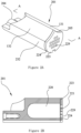
- FIG 2A shows the structure of an embodiment of a slide valve body (201), in accordance with the present disclosure.
- the slide valve body (201) has two screw rotor contact surfaces (131 and 132) and a slide valve slot contact surface (232), where the slide valve slot contact surface (232) is configured to contact the slide valve slot (190).
- the slide valve body (201) further has a connecting end (204) and a free end (205) which are arranged opposite one another, and the connecting end (204) and the free end (205) are respectively located at the two ends of the slide valve body (201).
- the connecting end (204) is configured to connect to the slide valve connecting rod (102) so that the slide valve connecting rod (102) can drive the slide valve body (201) to slide within the slide valve slot (190) when the slide valve connecting rod (102) moves.
- the free end (205) can form the air return passage (109) together with the screw rotors (92) and a housing of the compressor when the slide valve body (201) slides within the slide valve slot (190).
- a cover (223) is connected to an end face (224) of the free end (205), and the cover (223) has a plurality of holes (229).
- the holes (229) can be in any shape. In the embodiment shown in Figure 2A , the holes (229) are circular holes or approximately circular holes, and each hole (229) has the same size or a similar size.
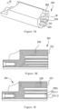
- Figure 2B is a cutaway view of an embodiment of the slide valve body (201) shown in Figure 2A , taken along line A-A of Figure 2A .
- the holes (229) pass through the cover (223) to form a plurality of passages (221).
- a cavity (220) is formed inside of the slide valve body (201). Specifically, the cavity (220) extends into the slide valve body (201) from the end face (224) of the free end (205).
- One end of each passage (221) is connected to the cavity (220), and the other end of each passage (221) is connected to an external fluid via the holes (229).
- the cavity (220) is configured to be fluidly connected to the external fluid via the passages (221).
- the cavity (220) accommodates the pulsating air flow by absorbing energy of the air flow pulsations and buffering the air flow.
- air flow pulsations are reduced, and vibrations and noise of the twin-screw compressor (90) are alleviated.
- the cavity (220) can be an integral cavity (220), as shown in Figure 2B .
- the cavity (220) can also be or include a plurality of cavities (320), as shown in Figure 3B and Figure 3C .
- no cover (223) may be provided on the end face (224) of the free end (205) of the slide valve body (201).
- the holes (329) can be directly formed in and on the end face (224) of the free end (205) so that one end of each of the passages (321) is connected to a respective one of the cavities (320), and the other end of each of the passages (321) is connected to external air flow via the direct passing of holes (329) through the end face (224) of the free end (205).
- the cavities (320) in the slide valve body (201) can be connected to the external air flow via the passages (321).
- holes (329) can have different sizes and/or shapes so that the passages (321) can also have different inside diameters.
- FIG 3B and Figure 3C are cutaway views of the slide valve body (201) shown in Figure 3A , taken along line B-B of Figure 3A , and show two exemplified embodiments in which a plurality of cavities (320) is provided in the slide valve body (201).
- a plurality of cavities (320) is provided in the slide valve body (201).
- the weight of the slide valve body (201) can be reduced and the reliability of the structure of the slide valve body (201) can be improved.
- each cavity (320) of said plurality of cavities (320) has its own passage (321) so that each cavity (320) of the plurality of cavities (320) is connected to external air flow via its own passage (321).
- a portion or subset of the plurality of cavities (320) has their own passage (321).
- Other cavities, such as cavity (3201), are connected to the external fluid via a plurality of passages (3211.1 and 3211.2).
- the cavity (320) may be larger than the cavities (320) having their own, single passage (321). Therefore, the ability of the cavities (320) to absorb air flow pulsations is improved, and the reliability of the structure of the slide valve body (201) is improved.
- the slide valve body (201) can have different shapes, depending on the type of the twin-screw compressor (90) having the slide valve body (201).
- Figure 4A shows the shape of a slide valve body (401).
- the slide valve body (401) has a connecting end (404) and a free end (405).
- the free end (405) has a free end extension portion (408) extending away from the free end (405).
- a top (409) of the free end extension portion (408) is lower than screw rotor contact surfaces (431 and 432) of the free end (405) so that a stepped connecting surface, such as stepped surface (410), is formed.
- the free end extension portion (408) can extend between a wall of the twin-screw compressor (90) cylinder and a housing of the screw rotors (92) when the slide valve (100) moves therein.
- the stability of the slide valve (100) during sliding is improved, and the reliability of the slide valve (100) is further improved.
- the free end extension portion (408) has holes (429) on a surface of the free end extension portion (408). Specifically, as shown in Figure 4A , the holes (429) can be located on the stepped surface (410) of the free end extension portion (408) or can be located on an outside surface (411) of the free end extension portion (408).
- Figure 4B shows a cutaway view of an embodiment of the slide valve body (401) shown in Figure 4A , taken along line C-C of Figure 4A .
- the free end extension portion (408) has an integral cavity (420) formed inside the free end extension portion (408), and the cavity (420) has a plurality of passages (421).
- the passages (421) are connected to an external fluid via holes (429), thereby fluidly connecting the cavity (420) with the external fluid.
- the outside surface (411) can have holes (429) or can be a closed end face.
- the free end extension portion (408) can have a plurality of cavities (420) formed therein, and the plurality of cavities (420) can be connected to the external fluid via one or more passages (421).
- air flow pulsations produced during operation of the twin-screw compressor (90) can be buffered via the cavities (420), and an air flow pulsation attenuating structure is formed.
- the slide valve body (101) of the present disclosure can be integrally formed as a one piece structure, via the use of molds, or the slide valve body can be formed by machining a conventional slide valve body.
- the machining method is simple and easy to realize.
Landscapes
- Engineering & Computer Science (AREA)
- General Engineering & Computer Science (AREA)
- Mechanical Engineering (AREA)
- Applications Or Details Of Rotary Compressors (AREA)
- Details Of Valves (AREA)
Description
- The present application relates to the field of compressors and, in particular, relates to a slide valve for a twin-screw compressor.
- The slide valve is an important component which enables load regulation of the twin-screw compressor. By moving the position of the slide valve in an axial direction of a screw rotor of the twin-screw compressor, the effective working length of the screw rotor can be changed to regulate the amount of air delivered by the twin-screw compressor.
- Discontinuous inter-tooth volumes may be formed via the engagement of the screw rotor of the twin-screw compressor, which may cause the suction cavity and the exhaust cavity of the twin-screw compressor to be periodically connected to the working cavity of the twin-screw compressor. As a result, the cooling medium fluid may flow unsteadily through the twin-screw compressor, which may cause air flow pulsations during suction and exhaust. The air flow pulsations on the suction side and exhaust side of the twin-screw compressor may cause vibrations and noise during operation of the twin-screw compressor. Therefore, it is desirable to reduce air flow pulsations of the twin-screw compressor.
- Because of the characteristics of the twin-screw compressor, fluid pressure pulsations may exist on both the suction side and the exhaust side of the twin-screw compressor, and the energy of the pulsations may correlate to an acoustic load of the fluid in the compressor. Currently, many technologies for governing exhaust pulsations are reflected in the construction of the structure of slide valves, but the structure of slide valves has not been effectively utilized to construct a pulsation attenuation design on the suction side of compressors to attenuate the energy of air flow pulsations, lower the overall pressure pulsation level in compressors, or alleviate vibrations and noise of compressors.
-
US 8 459 963 B2 discloses a slide valve for a twin compressor comprising a cavity and at least one passage configured to fluidly couple the cavity with an external fluid to reduce airflow pulsations on a discharge side of the twin-screw compressor. - To solve the above-mentioned problem, the objective of the present disclosure is to provide a slide valve for a twin-screw compressor. By attenuating the energy of air flow on a suction side of the twin-screw compressor to reduce the air flow pulsations on the suction side, the overall air flow pulsation level is lowered, and vibrations and noise of the twin-screw compressor are alleviated.
- To achieve the above-mentioned objective, in a first aspect, the present disclosure provides a slide valve configured to regulate a load of a twin-screw compressor.
- The slide valve comprises a slide valve body, the slide valve body has a connecting end and a free end, the connecting end is configured to connect to a slide valve connecting rod, and the slide valve is driven to slide within the twin-screw compressor by the slide valve connecting rod. A cavity is formed inside the free end of the slide valve body, and the slide valve has at least one passage configured to fluidly connect the cavity with an external fluid to reduce air flow pulsations on the suction side of the twin-screw compressor.
- According to present embodiments, one cavity is formed in the free end, the slide valve has a cover on an end face of the free end, the cover has a plurality of holes, and the plurality of holes is connected to the cavity to form a plurality of passages.
- According to present embodiments, each hole of the plurality of holes is circular, and each hole has the same size.
- According to present embodiments, a plurality of cavities is formed in the free end, and each cavity of the plurality of cavities has its own passage.
- According to present embodiments, a plurality of cavities is formed in the free end, a first set of the plurality of cavities has one respective passage each, and at least one cavity of the plurality of cavities has a plurality of passages.
- In a second aspect, the present disclosure provides a slide valve configured to regulate a load of a twin-screw compressor. The slide valve comprises a slide valve body, the slide valve body has a connecting end and a free end, the connecting end is configured to connect to a slide valve connecting rod to drive the slide valve to slide within the twin-screw compressor, and the free end of the slide valve body has a free end extension portion extending away from the free end. The free end extension portion has a cavity formed therein, and the slide valve has a passage configured to fluidly connect the cavity with an external fluid to reduce air flow pulsations on a suction side of the twin-screw compressor.
- According to present embodiments, the free end extension portion is configured to provide an additional support at partial load of the twin-screw compressor.
- According to present embodiments, the free end extension portion has holes on a surface of the free end extension portion, and the holes are connected to the cavity to form passages.
- According to present embodiments, the holes are provided on an outside surface of the free end extension portion.
- According to present embodiments, a top end of the free end extension portion is offset from a top end of the free end so that a stepped surface is formed, and the holes are formed in the stepped surface.
- In a third aspect, the present disclosure provides a twin-screw compressor, and the twin-screw compressor is configured to use a slide valve described in any of the above aspects.
- On the basis of the structure of a prior slide valve, the slide valve's function of regulating a load of a twin-screw compressor is reserved for the slide valve of the present disclosure. In addition, a fluid pulsation attenuating structure is formed by providing cavities in the slide valve body that are configured to connect to an external fluid so that energy of air flow pulsations on the suction side of the twin-screw compressor is reduced, the overall air flow pulsations in the twin-screw compressor are reduced, vibrations and noise of the twin-screw compressor are alleviated, and the running reliability of the twin-screw compressor at various loads is improved. Moreover, the structure of the present disclosure is simple, no additional attenuation device is used, and no extra pressure loss is caused.
- These and other characteristics and advantages of the present disclosure can be better understood by reading the following description with reference to the drawings. In all the drawings, the same reference number represents the same component, wherein
-
Figure 1A is a cutaway view of a twin-screw compressor in the longitudinal direction of a screw rotor, where the slide valve is provided below the screw rotor. -
Figure 1B is a partial cutaway view of a twin-screw compressor in the longitudinal direction of a screw rotor and shows a position (above the screw rotor) of the slide valve at full load. -
Figure 1C is a partial cutaway view of a twin-screw compressor in the longitudinal direction of a screw rotor and shows a position (above the screw rotor) of the slide valve at partial load. -
Figure 1D is a cutaway view of the embodiment shown inFigure 1B , taken along line D-D ofFigure 1B , and shows a position relationship between the slide valve and the screw rotors of the twin-screw compressor. -
Figure 2A is a perspective view of a slide valve body in one embodiment of the present disclosure. -
Figure 2B is a cutaway view of the embodiment of the slide valve body shown inFigure 2A , taken along line A-A ofFigure 2A . -
Figure 3A is a perspective view of a slide valve body of another embodiment of the present disclosure. -
Figure 3B is a cutaway view of the embodiment of the slide valve body shown inFigure 3A , taken along line B-B ofFigure 3A . -
Figure 3C is a cutaway view of the embodiment of the slide valve body shown inFigure 3A , taken along line B-B ofFigure 3A . -
Figure 4A is a perspective view of a slide valve body of a third embodiment of the present disclosure. -
Figure 4B is a cutaway view of the embodiment of the slide valve body shown inFigure 4A , taken along line C-C ofFigure 4A . - The following will describe various specific implementation modes of the present disclosure by reference to the drawings which constitute a part of the present description. It should be understood that although the terms indicating directions, such as "before", "behind", "above", "below", "left", and "right" are used in the present disclosure to describe various exemplified structural parts and components of the present disclosure, these terms are just used for the convenience of illustrations and are determined based on the exemplified directions in the drawings. Since the embodiments disclosed in the present disclosure can be set in different directions, these terms indicating directions are only used for illustrations, instead of restrictions. In the following drawings, the same components use the same reference numbers, and similar components use similar reference numbers so as to avoid repeated descriptions.
-
Figure 1A is a cutaway view of a twin-screw compressor (90) in the longitudinal direction of a screw rotor (92), where a slide valve (100) is provided below the screw rotor (92). However, the slide valve (100) can be provided above the screw rotor (92), as shown inFigure 1B and Figure 1C . -
Figure 1B is a partial cutaway view of the twin-screw compressor (90) in the longitudinal direction of the screw rotor (92) and shows a position of the slide valve (100) at full load, andFigure 1C is a partial cutaway view of the twin-screw compressor (90) in the longitudinal direction of the screw rotor (92) and shows a position of the slide valve (100) at partial load. As shown inFigure 1B and Figure 1C , the slide valve (100) of the present disclosure is used in the twin-screw compressor (90) and comprises a slide valve body (101), a slide valve connecting rod (102) connected to a connecting end of the slide valve body (101), a spring (106) placed on the slide valve body (101), and a piston (103) connected to an end of the slide valve connecting rod (102). The slide valve connecting rod (102) can drive the slide valve body (101) to slide in a slide valve slot (190) so that an air return passage (109) can be formed between the slide valve body (101) and a cylinder of the compressor (90). Therefore, the effective working length of screw rotors (92) of the twin-screw compressor (90) can be adjusted to regulate a load of the twin-screw compressor (90) by adjusting a position of the slide valve body (101) in the slide valve slot (190).Figure 1B shows the position of the slide valve (100) in the twin-screw compressor (90) at full load, where the slide valve body (101) is completely located in the slide valve slot (190), and the slide valve slot (190) is fully filled by the slide valve body (101) so that cooling medium vapors drawn in from a suction side (107) of the twin-screw compressor (90) are completely compressed and discharged.Figure 1C shows the position of the slide valve (100) in the twin-screw compressor (92) at partial load, where a portion of the slide valve body (101) is located in the slide valve slot (190) so that the slide valve slot (190) forms the air return passage (109) and a part of the cooling medium vapors drawn in from the suction side (107) are not compressed and instead return to the suction side (107) via the air return passage (109). Therefore, the effective working length of the screw rotors (92) is shortened in the configuration shown inFigure 1C . - To more clearly show the relationship between the slide valve (100) and the screw rotors (92) of the twin-screw compressor (90),
Figure 1D is a cutaway view of the twin-screw compressor (90) shown inFigure 1B , taken along line D-D ofFigure 1B , where the slide valve body (101) has at least two screw rotor contact surfaces (131 and 132). The two rotor contact surfaces (131 and 132) respectively contact a pair of screw rotors (92), and a sealing interface is formed between the rotor contact surfaces (131 and 132) and the screw rotors (92). -
Figure 2A shows the structure of an embodiment of a slide valve body (201), in accordance with the present disclosure. The slide valve body (201) has two screw rotor contact surfaces (131 and 132) and a slide valve slot contact surface (232), where the slide valve slot contact surface (232) is configured to contact the slide valve slot (190). The slide valve body (201) further has a connecting end (204) and a free end (205) which are arranged opposite one another, and the connecting end (204) and the free end (205) are respectively located at the two ends of the slide valve body (201). The connecting end (204) is configured to connect to the slide valve connecting rod (102) so that the slide valve connecting rod (102) can drive the slide valve body (201) to slide within the slide valve slot (190) when the slide valve connecting rod (102) moves. The free end (205) can form the air return passage (109) together with the screw rotors (92) and a housing of the compressor when the slide valve body (201) slides within the slide valve slot (190). - As shown in
Figure 2A , a cover (223) is connected to an end face (224) of the free end (205), and the cover (223) has a plurality of holes (229). The holes (229) can be in any shape. In the embodiment shown inFigure 2A , the holes (229) are circular holes or approximately circular holes, and each hole (229) has the same size or a similar size. - To show the internal structure of the slide valve body (201),
Figure 2B is a cutaway view of an embodiment of the slide valve body (201) shown inFigure 2A , taken along line A-A ofFigure 2A . As shown inFigure 2B , the holes (229) pass through the cover (223) to form a plurality of passages (221). A cavity (220) is formed inside of the slide valve body (201). Specifically, the cavity (220) extends into the slide valve body (201) from the end face (224) of the free end (205). One end of each passage (221) is connected to the cavity (220), and the other end of each passage (221) is connected to an external fluid via the holes (229). Thus, the cavity (220) is configured to be fluidly connected to the external fluid via the passages (221). - When air flow of the twin-screw compressor (90) pulsates, the cavity (220) accommodates the pulsating air flow by absorbing energy of the air flow pulsations and buffering the air flow. Thus, air flow pulsations are reduced, and vibrations and noise of the twin-screw compressor (90) are alleviated.
- As an exemplified embodiment, the cavity (220) can be an integral cavity (220), as shown in
Figure 2B . In other exemplified embodiments, the cavity (220) can also be or include a plurality of cavities (320), as shown inFigure 3B and Figure 3C . - As another implementation of the present disclosure, no cover (223) may be provided on the end face (224) of the free end (205) of the slide valve body (201). As shown in
Figure 3A , the holes (329) can be directly formed in and on the end face (224) of the free end (205) so that one end of each of the passages (321) is connected to a respective one of the cavities (320), and the other end of each of the passages (321) is connected to external air flow via the direct passing of holes (329) through the end face (224) of the free end (205). Thus, the cavities (320) in the slide valve body (201) can be connected to the external air flow via the passages (321). As an exemplified embodiment, holes (329) can have different sizes and/or shapes so that the passages (321) can also have different inside diameters. -
Figure 3B and Figure 3C are cutaway views of the slide valve body (201) shown inFigure 3A , taken along line B-B ofFigure 3A , and show two exemplified embodiments in which a plurality of cavities (320) is provided in the slide valve body (201). By providing the plurality of cavities (320) in the slide valve body (201), the weight of the slide valve body (201) can be reduced and the reliability of the structure of the slide valve body (201) can be improved. In the exemplified embodiment shown inFigure 3B , each cavity (320) of said plurality of cavities (320) has its own passage (321) so that each cavity (320) of the plurality of cavities (320) is connected to external air flow via its own passage (321). In the exemplified embodiment shown inFigure 3C , a portion or subset of the plurality of cavities (320) has their own passage (321). Other cavities, such as cavity (3201), are connected to the external fluid via a plurality of passages (3211.1 and 3211.2). As an exemplified embodiment, when one of the cavities (320) is connected to the external fluid via the plurality of passages (3211.1 and 3211.2), the cavity (320) may be larger than the cavities (320) having their own, single passage (321). Therefore, the ability of the cavities (320) to absorb air flow pulsations is improved, and the reliability of the structure of the slide valve body (201) is improved. - The slide valve body (201) can have different shapes, depending on the type of the twin-screw compressor (90) having the slide valve body (201). As an exemplified embodiment,
Figure 4A shows the shape of a slide valve body (401). The slide valve body (401) has a connecting end (404) and a free end (405). The free end (405) has a free end extension portion (408) extending away from the free end (405). A top (409) of the free end extension portion (408) is lower than screw rotor contact surfaces (431 and 432) of the free end (405) so that a stepped connecting surface, such as stepped surface (410), is formed. If space in the twin-screw compressor (90) permits, the free end extension portion (408) can extend between a wall of the twin-screw compressor (90) cylinder and a housing of the screw rotors (92) when the slide valve (100) moves therein. Thus, the stability of the slide valve (100) during sliding is improved, and the reliability of the slide valve (100) is further improved. - The free end extension portion (408) has holes (429) on a surface of the free end extension portion (408). Specifically, as shown in
Figure 4A , the holes (429) can be located on the stepped surface (410) of the free end extension portion (408) or can be located on an outside surface (411) of the free end extension portion (408).Figure 4B shows a cutaway view of an embodiment of the slide valve body (401) shown inFigure 4A , taken along line C-C ofFigure 4A . As shown inFigure 4B , the free end extension portion (408) has an integral cavity (420) formed inside the free end extension portion (408), and the cavity (420) has a plurality of passages (421). The passages (421) are connected to an external fluid via holes (429), thereby fluidly connecting the cavity (420) with the external fluid. The outside surface (411) can have holes (429) or can be a closed end face. - Similar to
Figure 3B and Figure 3C , the free end extension portion (408) can have a plurality of cavities (420) formed therein, and the plurality of cavities (420) can be connected to the external fluid via one or more passages (421). Thus, air flow pulsations produced during operation of the twin-screw compressor (90) can be buffered via the cavities (420), and an air flow pulsation attenuating structure is formed. - The slide valve body (101) of the present disclosure can be integrally formed as a one piece structure, via the use of molds, or the slide valve body can be formed by machining a conventional slide valve body. The machining method is simple and easy to realize.
- Although some characteristics of the present disclosure are shown and described in the present discussion, those skilled in the art can make various improvements and modifications. Therefore, it should be understood that the attached claims are intended to cover the above-mentioned improvements and modifications within the scope of the present invention as defined in the appended claims.
Claims (10)
- A slide valve (100) configured to regulate a load of a twin-screw compressor (90), comprising:
a slide valve body (201) of the slide valve (100), wherein the slide valve body (201) has a connecting end (204) and a free end (205), the connecting end (204) is configured to connect to a slide valve connecting rod (102) of the twin-screw compressor (90), the slide valve (100) is configured to be driven by the slide valve connecting rod (102), a cavity (220) is formed in the free end (205) and extends into the slide valve body (201), and the slide valve (100) has at least one passage (221) configured to fluidly couple the cavity (220) to an external fluid to reduce air flow pulsations on a suction side of the twin-screw compressor (90). - The slide valve (100) of claim 1, wherein the cavity (220) comprises a single cavity (220), the slide valve (100) has a cover (223) on an end face (224) of the free end (205), the cover (223) has a plurality of holes (229), and the plurality of holes (229) is fluidly connected to the single cavity (220) to form a plurality of passages (221) comprising the at least one passage (221).
- The slide valve (100) of claim 2, wherein each hole (229) of the plurality of holes (229) is circular and each hole (229) of the plurality of holes (229) has the same size.
- The slide valve (100) of claim 1, wherein the cavity (220) is one of a plurality of cavities (320) formed in the free end (205), and each cavity (320) of the plurality of cavities (320) has its own single passage (321).
- The slide valve (100) of claim 1, wherein the cavity (220) is one of a plurality of cavities (320) formed in the free end (205), the plurality of cavities (320) comprises a first set of cavities (320), each cavity (320) of the first set of cavities (320) having a single passage (321), and wherein the plurality of cavities (320) comprises a second cavity (3201), wherein the second cavity (3201) is not in the first set of cavities (320), and the second cavity (3201) has a plurality of passages (3211.1, 3211.2).
- A slide valve (100) configured to regulate a load of a twin-screw compressor (90), comprising:
a slide valve body (401) of the slide valve (100), wherein the slide valve body (401) has a connecting end (404) and a free end (405), wherein the connecting end (404) is configured to connect to a slide valve connecting rod (102) of the twin-screw compressor (90) to drive the slide valve (100) in a sliding motion within the twin-screw compressor (90), wherein the free end (405) of the slide valve body (401) has a free end extension portion (408) extending away from the free end (405), wherein a cavity (420) is formed in the free end extension portion (408), and wherein the slide valve (100) has a passage (421) configured to fluidly couple the cavity (420) with an external fluid to reduce air flow pulsations on a suction side of the twin-screw compressor (90). - The slide valve (100) of claim 6, wherein the free end extension portion (408) is configured to provide an additional support at partial load of the twin-screw compressor (90).
- The slide valve (100) of claim 6, wherein the free end extension portion (408) has holes (429) formed in a surface (410) of the free end extension portion (408), and the holes (429) are connected to the cavity (420) to form the passage (421) and additional passages (421).
- The slide valve (100) of claim 8, wherein the holes (429) are formed in an outside surface (411) of the free end extension portion (408).
- The slide valve (100) of claim 8, wherein a top end (409) of the free end extension portion (408) is offset from a top end (431, 432) of the free end (405), such that a stepped surface (410) is formed, and the holes (429) are formed in the stepped surface (410).
Applications Claiming Priority (2)
| Application Number | Priority Date | Filing Date | Title |
|---|---|---|---|
| CN201721291991.9U CN208089547U (en) | 2017-09-30 | 2017-09-30 | A kind of guiding valve |
| PCT/IB2018/057427 WO2019064187A1 (en) | 2017-09-30 | 2018-09-26 | A slide valve for a twin-screw compressor |
Publications (2)
| Publication Number | Publication Date |
|---|---|
| EP3688310A1 EP3688310A1 (en) | 2020-08-05 |
| EP3688310B1 true EP3688310B1 (en) | 2024-10-30 |
Family
ID=63857993
Family Applications (1)
| Application Number | Title | Priority Date | Filing Date |
|---|---|---|---|
| EP18786410.3A Active EP3688310B1 (en) | 2017-09-30 | 2018-09-26 | A slide valve for a twin-screw compressor |
Country Status (7)
| Country | Link |
|---|---|
| US (2) | US11913453B2 (en) |
| EP (1) | EP3688310B1 (en) |
| JP (3) | JP2020536194A (en) |
| KR (1) | KR20200060427A (en) |
| CN (1) | CN208089547U (en) |
| TW (2) | TWI802303B (en) |
| WO (1) | WO2019064187A1 (en) |
Families Citing this family (7)
| Publication number | Priority date | Publication date | Assignee | Title |
|---|---|---|---|---|
| CN208089547U (en) * | 2017-09-30 | 2018-11-13 | 江森自控空调冷冻设备(无锡)有限公司 | A kind of guiding valve |
| CN108661906B (en) * | 2018-08-13 | 2020-01-03 | 珠海格力电器股份有限公司 | Slide valve, slide valve adjusting mechanism and screw compressor |
| US11920594B2 (en) * | 2018-09-17 | 2024-03-05 | Xi'an Jiaotong University | Screw compressor slide valve and screw compressor with gas pulsation attenuation function |
| GB2581526A (en) | 2019-02-22 | 2020-08-26 | J & E Hall Ltd | Single screw compressor |
| CN115038872B (en) * | 2020-01-07 | 2024-10-29 | 江森自控泰科知识产权控股有限责任合伙公司 | Volume ratio control system for compressors |
| CN115596667B (en) * | 2022-11-09 | 2023-08-11 | 爱景智能装备(无锡)有限公司 | Air inlet adjusting structure and method of double-screw compressor |
| CN121429611A (en) * | 2024-07-29 | 2026-01-30 | 开利公司 | Screw compressor and its slide valve |
Citations (1)
| Publication number | Priority date | Publication date | Assignee | Title |
|---|---|---|---|---|
| US8459963B2 (en) * | 2007-10-10 | 2013-06-11 | Carrier Corporation | Screw compressor pulsation damper |
Family Cites Families (21)
| Publication number | Priority date | Publication date | Assignee | Title |
|---|---|---|---|---|
| US3151806A (en) * | 1962-09-24 | 1964-10-06 | Joseph E Whitfield | Screw type compressor having variable volume and adjustable compression |
| JPS5930919B2 (en) * | 1974-12-24 | 1984-07-30 | 北越工業 (株) | Liquid volume and gas capacity adjustment device for liquid-cooled rotary compressors |
| JPS56143388A (en) * | 1980-04-11 | 1981-11-09 | Hitachi Ltd | Slide valve for screw compressor |
| US4575323A (en) * | 1984-05-23 | 1986-03-11 | Kabushiki Kaisha Kobe Seiko Sho | Slide valve type screw compressor |
| JPH02169891A (en) * | 1988-12-21 | 1990-06-29 | Hitachi Ltd | rotary compressor |
| JPH07217563A (en) * | 1994-01-31 | 1995-08-15 | Ebara Corp | Hollow rotor for screw fluid machinery |
| JPH1082385A (en) * | 1996-09-09 | 1998-03-31 | Ishikawajima Harima Heavy Ind Co Ltd | Casing structure of resholm type compressor |
| JP3502772B2 (en) * | 1997-09-10 | 2004-03-02 | 株式会社神戸製鋼所 | Screw compressor |
| US6205808B1 (en) | 1999-09-03 | 2001-03-27 | American Standard Inc. | Prevention of oil backflow from a screw compressor in a refrigeration chiller |
| DE10242139A1 (en) * | 2002-09-03 | 2004-03-18 | Bitzer Kühlmaschinenbau Gmbh | screw compressors |
| WO2004051089A1 (en) * | 2002-12-03 | 2004-06-17 | Bitzer Kühlmaschinenbau Gmbh | Screw compressor |
| JP4403739B2 (en) * | 2003-07-11 | 2010-01-27 | ダイキン工業株式会社 | Screw compressor |
| US20060165543A1 (en) * | 2005-01-24 | 2006-07-27 | York International Corporation | Screw compressor acoustic resonance reduction |
| WO2006096178A1 (en) * | 2005-03-07 | 2006-09-14 | Carrier Corporation | Compressor sound suppression |
| JP4265577B2 (en) * | 2005-06-30 | 2009-05-20 | 日立アプライアンス株式会社 | Two stage screw compressor |
| CN202326251U (en) | 2011-11-24 | 2012-07-11 | 江森自控空调冷冻设备(无锡)有限公司 | Slide valve with silencing structure for screw compressor |
| CN202789520U (en) | 2012-02-24 | 2013-03-13 | 开利公司 | Helical-lobe compressor and slide valve thereof |
| CN202752879U (en) * | 2012-08-23 | 2013-02-27 | 联德机械(杭州)有限公司 | Sliding valve tool of double screw rod compressor |
| CN208089547U (en) * | 2017-09-30 | 2018-11-13 | 江森自控空调冷冻设备(无锡)有限公司 | A kind of guiding valve |
| CN109058115B (en) * | 2018-09-17 | 2019-12-24 | 西安交通大学 | A screw compressor slide valve with airflow pulsation attenuation function |
| US11920594B2 (en) * | 2018-09-17 | 2024-03-05 | Xi'an Jiaotong University | Screw compressor slide valve and screw compressor with gas pulsation attenuation function |
-
2017
- 2017-09-30 CN CN201721291991.9U patent/CN208089547U/en active Active
-
2018
- 2018-09-26 KR KR1020207011320A patent/KR20200060427A/en not_active Ceased
- 2018-09-26 JP JP2020517832A patent/JP2020536194A/en active Pending
- 2018-09-26 TW TW111107487A patent/TWI802303B/en active
- 2018-09-26 EP EP18786410.3A patent/EP3688310B1/en active Active
- 2018-09-26 TW TW107133878A patent/TWI759548B/en active
- 2018-09-26 US US16/652,378 patent/US11913453B2/en active Active
- 2018-09-26 WO PCT/IB2018/057427 patent/WO2019064187A1/en not_active Ceased
-
2023
- 2023-04-11 JP JP2023064061A patent/JP7707227B2/en active Active
-
2024
- 2024-02-26 US US18/587,571 patent/US12429053B2/en active Active
-
2025
- 2025-07-02 JP JP2025112272A patent/JP2025134991A/en active Pending
Patent Citations (1)
| Publication number | Priority date | Publication date | Assignee | Title |
|---|---|---|---|---|
| US8459963B2 (en) * | 2007-10-10 | 2013-06-11 | Carrier Corporation | Screw compressor pulsation damper |
Also Published As
| Publication number | Publication date |
|---|---|
| CN208089547U (en) | 2018-11-13 |
| TWI802303B (en) | 2023-05-11 |
| JP2020536194A (en) | 2020-12-10 |
| US12429053B2 (en) | 2025-09-30 |
| US11913453B2 (en) | 2024-02-27 |
| US20200291942A1 (en) | 2020-09-17 |
| TW202229726A (en) | 2022-08-01 |
| JP2025134991A (en) | 2025-09-17 |
| WO2019064187A1 (en) | 2019-04-04 |
| TWI759548B (en) | 2022-04-01 |
| EP3688310A1 (en) | 2020-08-05 |
| JP7707227B2 (en) | 2025-07-14 |
| US20240191713A1 (en) | 2024-06-13 |
| TW201934877A (en) | 2019-09-01 |
| KR20200060427A (en) | 2020-05-29 |
| JP2023089107A (en) | 2023-06-27 |
Similar Documents
| Publication | Publication Date | Title |
|---|---|---|
| US12429053B2 (en) | Slide valve for a twin-screw compressor | |
| CN108915997B (en) | Muffler, compressor assembly and refrigerator | |
| CN108661906B (en) | Slide valve, slide valve adjusting mechanism and screw compressor | |
| CN1578877A (en) | Suction mufflers for hermetic reciprocating compressors | |
| CN101821479A (en) | Slide valve system for screw compressors | |
| KR20110013444A (en) | Release valve device for hermetic compressor | |
| JP2005139909A (en) | Oil pump | |
| CN104110363B (en) | Compressor and refrigeration cycling device provided with same | |
| CN113494451B (en) | Compression mechanism and scroll compressor | |
| EP3816442B1 (en) | Compressor and electronic device using same | |
| CN212536070U (en) | Novel swing rotor compressor with low-pressure cavity in shell | |
| EP2580475B1 (en) | A hermetic compressor | |
| JPH05149254A (en) | Silencing device for compressor | |
| JP4684237B2 (en) | Discharge system for compressor | |
| JPH04143491A (en) | Compressor with rolling piston | |
| CN221053860U (en) | Compressor and refrigeration equipment | |
| CN203962347U (en) | Compressor and there is its refrigerating circulatory device | |
| CN106151034B (en) | Rotary compressor | |
| CN111720326A (en) | A Novel Swing Rotor Compressor with Low Pressure Chamber in Shell | |
| EP3336355A1 (en) | Hermetic compressor | |
| JP7835609B2 (en) | Gas flow regulator and reciprocating compressor | |
| CN101684788A (en) | Silencer for compressor | |
| CN109505771B (en) | Compressors, Air Conditioning Systems and Vehicles | |
| CN121229397A (en) | Cylinders and compressors used in compressors | |
| CN117212106A (en) | Pump components and compressors |
Legal Events
| Date | Code | Title | Description |
|---|---|---|---|
| STAA | Information on the status of an ep patent application or granted ep patent |
Free format text: STATUS: UNKNOWN |
|
| STAA | Information on the status of an ep patent application or granted ep patent |
Free format text: STATUS: THE INTERNATIONAL PUBLICATION HAS BEEN MADE |
|
| PUAI | Public reference made under article 153(3) epc to a published international application that has entered the european phase |
Free format text: ORIGINAL CODE: 0009012 |
|
| STAA | Information on the status of an ep patent application or granted ep patent |
Free format text: STATUS: REQUEST FOR EXAMINATION WAS MADE |
|
| 17P | Request for examination filed |
Effective date: 20200421 |
|
| AK | Designated contracting states |
Kind code of ref document: A1 Designated state(s): AL AT BE BG CH CY CZ DE DK EE ES FI FR GB GR HR HU IE IS IT LI LT LU LV MC MK MT NL NO PL PT RO RS SE SI SK SM TR |
|
| AX | Request for extension of the european patent |
Extension state: BA ME |
|
| DAV | Request for validation of the european patent (deleted) | ||
| DAX | Request for extension of the european patent (deleted) | ||
| STAA | Information on the status of an ep patent application or granted ep patent |
Free format text: STATUS: EXAMINATION IS IN PROGRESS |
|
| 17Q | First examination report despatched |
Effective date: 20221124 |
|
| GRAP | Despatch of communication of intention to grant a patent |
Free format text: ORIGINAL CODE: EPIDOSNIGR1 |
|
| STAA | Information on the status of an ep patent application or granted ep patent |
Free format text: STATUS: GRANT OF PATENT IS INTENDED |
|
| INTG | Intention to grant announced |
Effective date: 20240607 |
|
| GRAS | Grant fee paid |
Free format text: ORIGINAL CODE: EPIDOSNIGR3 |
|
| GRAA | (expected) grant |
Free format text: ORIGINAL CODE: 0009210 |
|
| STAA | Information on the status of an ep patent application or granted ep patent |
Free format text: STATUS: THE PATENT HAS BEEN GRANTED |
|
| AK | Designated contracting states |
Kind code of ref document: B1 Designated state(s): AL AT BE BG CH CY CZ DE DK EE ES FI FR GB GR HR HU IE IS IT LI LT LU LV MC MK MT NL NO PL PT RO RS SE SI SK SM TR |
|
| REG | Reference to a national code |
Ref country code: GB Ref legal event code: FG4D |
|
| REG | Reference to a national code |
Ref country code: CH Ref legal event code: EP |
|
| REG | Reference to a national code |
Ref country code: IE Ref legal event code: FG4D |
|
| REG | Reference to a national code |
Ref country code: DE Ref legal event code: R096 Ref document number: 602018076022 Country of ref document: DE |
|
| REG | Reference to a national code |
Ref country code: LT Ref legal event code: MG9D |
|
| REG | Reference to a national code |
Ref country code: NL Ref legal event code: MP Effective date: 20241030 |
|
| PG25 | Lapsed in a contracting state [announced via postgrant information from national office to epo] |
Ref country code: HR Free format text: LAPSE BECAUSE OF FAILURE TO SUBMIT A TRANSLATION OF THE DESCRIPTION OR TO PAY THE FEE WITHIN THE PRESCRIBED TIME-LIMIT Effective date: 20241030 Ref country code: IS Free format text: LAPSE BECAUSE OF FAILURE TO SUBMIT A TRANSLATION OF THE DESCRIPTION OR TO PAY THE FEE WITHIN THE PRESCRIBED TIME-LIMIT Effective date: 20250228 Ref country code: PT Free format text: LAPSE BECAUSE OF FAILURE TO SUBMIT A TRANSLATION OF THE DESCRIPTION OR TO PAY THE FEE WITHIN THE PRESCRIBED TIME-LIMIT Effective date: 20250228 |
|
| PG25 | Lapsed in a contracting state [announced via postgrant information from national office to epo] |
Ref country code: FI Free format text: LAPSE BECAUSE OF FAILURE TO SUBMIT A TRANSLATION OF THE DESCRIPTION OR TO PAY THE FEE WITHIN THE PRESCRIBED TIME-LIMIT Effective date: 20241030 Ref country code: NL Free format text: LAPSE BECAUSE OF FAILURE TO SUBMIT A TRANSLATION OF THE DESCRIPTION OR TO PAY THE FEE WITHIN THE PRESCRIBED TIME-LIMIT Effective date: 20241030 |
|
| REG | Reference to a national code |
Ref country code: AT Ref legal event code: MK05 Ref document number: 1737104 Country of ref document: AT Kind code of ref document: T Effective date: 20241030 |
|
| PG25 | Lapsed in a contracting state [announced via postgrant information from national office to epo] |
Ref country code: BG Free format text: LAPSE BECAUSE OF FAILURE TO SUBMIT A TRANSLATION OF THE DESCRIPTION OR TO PAY THE FEE WITHIN THE PRESCRIBED TIME-LIMIT Effective date: 20241030 |
|
| PG25 | Lapsed in a contracting state [announced via postgrant information from national office to epo] |
Ref country code: ES Free format text: LAPSE BECAUSE OF FAILURE TO SUBMIT A TRANSLATION OF THE DESCRIPTION OR TO PAY THE FEE WITHIN THE PRESCRIBED TIME-LIMIT Effective date: 20241030 |
|
| PG25 | Lapsed in a contracting state [announced via postgrant information from national office to epo] |
Ref country code: NO Free format text: LAPSE BECAUSE OF FAILURE TO SUBMIT A TRANSLATION OF THE DESCRIPTION OR TO PAY THE FEE WITHIN THE PRESCRIBED TIME-LIMIT Effective date: 20250130 |
|
| PG25 | Lapsed in a contracting state [announced via postgrant information from national office to epo] |
Ref country code: AT Free format text: LAPSE BECAUSE OF FAILURE TO SUBMIT A TRANSLATION OF THE DESCRIPTION OR TO PAY THE FEE WITHIN THE PRESCRIBED TIME-LIMIT Effective date: 20241030 Ref country code: LV Free format text: LAPSE BECAUSE OF FAILURE TO SUBMIT A TRANSLATION OF THE DESCRIPTION OR TO PAY THE FEE WITHIN THE PRESCRIBED TIME-LIMIT Effective date: 20241030 Ref country code: GR Free format text: LAPSE BECAUSE OF FAILURE TO SUBMIT A TRANSLATION OF THE DESCRIPTION OR TO PAY THE FEE WITHIN THE PRESCRIBED TIME-LIMIT Effective date: 20250131 |
|
| PG25 | Lapsed in a contracting state [announced via postgrant information from national office to epo] |
Ref country code: PL Free format text: LAPSE BECAUSE OF FAILURE TO SUBMIT A TRANSLATION OF THE DESCRIPTION OR TO PAY THE FEE WITHIN THE PRESCRIBED TIME-LIMIT Effective date: 20241030 |
|
| PG25 | Lapsed in a contracting state [announced via postgrant information from national office to epo] |
Ref country code: RS Free format text: LAPSE BECAUSE OF FAILURE TO SUBMIT A TRANSLATION OF THE DESCRIPTION OR TO PAY THE FEE WITHIN THE PRESCRIBED TIME-LIMIT Effective date: 20250130 |
|
| PG25 | Lapsed in a contracting state [announced via postgrant information from national office to epo] |
Ref country code: SM Free format text: LAPSE BECAUSE OF FAILURE TO SUBMIT A TRANSLATION OF THE DESCRIPTION OR TO PAY THE FEE WITHIN THE PRESCRIBED TIME-LIMIT Effective date: 20241030 |
|
| PG25 | Lapsed in a contracting state [announced via postgrant information from national office to epo] |
Ref country code: DK Free format text: LAPSE BECAUSE OF FAILURE TO SUBMIT A TRANSLATION OF THE DESCRIPTION OR TO PAY THE FEE WITHIN THE PRESCRIBED TIME-LIMIT Effective date: 20241030 |
|
| PG25 | Lapsed in a contracting state [announced via postgrant information from national office to epo] |
Ref country code: EE Free format text: LAPSE BECAUSE OF FAILURE TO SUBMIT A TRANSLATION OF THE DESCRIPTION OR TO PAY THE FEE WITHIN THE PRESCRIBED TIME-LIMIT Effective date: 20241030 |
|
| PG25 | Lapsed in a contracting state [announced via postgrant information from national office to epo] |
Ref country code: RO Free format text: LAPSE BECAUSE OF FAILURE TO SUBMIT A TRANSLATION OF THE DESCRIPTION OR TO PAY THE FEE WITHIN THE PRESCRIBED TIME-LIMIT Effective date: 20241030 |
|
| PG25 | Lapsed in a contracting state [announced via postgrant information from national office to epo] |
Ref country code: SK Free format text: LAPSE BECAUSE OF FAILURE TO SUBMIT A TRANSLATION OF THE DESCRIPTION OR TO PAY THE FEE WITHIN THE PRESCRIBED TIME-LIMIT Effective date: 20241030 |
|
| PG25 | Lapsed in a contracting state [announced via postgrant information from national office to epo] |
Ref country code: CZ Free format text: LAPSE BECAUSE OF FAILURE TO SUBMIT A TRANSLATION OF THE DESCRIPTION OR TO PAY THE FEE WITHIN THE PRESCRIBED TIME-LIMIT Effective date: 20241030 |
|
| REG | Reference to a national code |
Ref country code: DE Ref legal event code: R097 Ref document number: 602018076022 Country of ref document: DE |
|
| RAP2 | Party data changed (patent owner data changed or rights of a patent transferred) |
Owner name: JOHNSON CONTROLS AIR CONDITIONINGAND REFRIGERATION COMPANY (WUXI) CO., LTD Owner name: JOHNSON CONTROLS TYCO IP HOLDINGS LLP |
|
| PLBE | No opposition filed within time limit |
Free format text: ORIGINAL CODE: 0009261 |
|
| STAA | Information on the status of an ep patent application or granted ep patent |
Free format text: STATUS: NO OPPOSITION FILED WITHIN TIME LIMIT |
|
| PG25 | Lapsed in a contracting state [announced via postgrant information from national office to epo] |
Ref country code: SE Free format text: LAPSE BECAUSE OF FAILURE TO SUBMIT A TRANSLATION OF THE DESCRIPTION OR TO PAY THE FEE WITHIN THE PRESCRIBED TIME-LIMIT Effective date: 20241030 |
|
| 26N | No opposition filed |
Effective date: 20250731 |
|
| PGFP | Annual fee paid to national office [announced via postgrant information from national office to epo] |
Ref country code: DE Payment date: 20250926 Year of fee payment: 8 |
|
| PGFP | Annual fee paid to national office [announced via postgrant information from national office to epo] |
Ref country code: IT Payment date: 20250922 Year of fee payment: 8 |
|
| REG | Reference to a national code |
Ref country code: DE Ref legal event code: R081 Ref document number: 602018076022 Country of ref document: DE Owner name: JOHNSON CONTROLS AIR CONDITIONING AND REFRIGER, CN Free format text: FORMER OWNERS: JOHNSON CONTROLS AIR CONDITIONING AND REFRIGERATION COMPANY (WUXI) CO., LTD., WUXI, JIANGSU, CN; JOHNSON CONTROLS TECHNOLOGY COMPANY, AUBURN HILLS, MI, US Ref country code: DE Ref legal event code: R081 Ref document number: 602018076022 Country of ref document: DE Owner name: JOHNSON CONTROLS TYCO IP HOLDINGS LLP, MILWAUK, US Free format text: FORMER OWNERS: JOHNSON CONTROLS AIR CONDITIONING AND REFRIGERATION COMPANY (WUXI) CO., LTD., WUXI, JIANGSU, CN; JOHNSON CONTROLS TECHNOLOGY COMPANY, AUBURN HILLS, MI, US |
|
| REG | Reference to a national code |
Ref country code: CH Ref legal event code: H13 Free format text: ST27 STATUS EVENT CODE: U-0-0-H10-H13 (AS PROVIDED BY THE NATIONAL OFFICE) Effective date: 20260504 |