EP3687893B1 - Back pack cinch - Google Patents
Back pack cinch Download PDFInfo
- Publication number
- EP3687893B1 EP3687893B1 EP18857589.8A EP18857589A EP3687893B1 EP 3687893 B1 EP3687893 B1 EP 3687893B1 EP 18857589 A EP18857589 A EP 18857589A EP 3687893 B1 EP3687893 B1 EP 3687893B1
- Authority
- EP
- European Patent Office
- Prior art keywords
- tab
- strap
- cover
- cinch
- closed position
- Prior art date
- Legal status (The legal status is an assumption and is not a legal conclusion. Google has not performed a legal analysis and makes no representation as to the accuracy of the status listed.)
- Active
Links
Images


Classifications
-
- B—PERFORMING OPERATIONS; TRANSPORTING
- B63—SHIPS OR OTHER WATERBORNE VESSELS; RELATED EQUIPMENT
- B63C—LAUNCHING, HAULING-OUT, OR DRY-DOCKING OF VESSELS; LIFE-SAVING IN WATER; EQUIPMENT FOR DWELLING OR WORKING UNDER WATER; MEANS FOR SALVAGING OR SEARCHING FOR UNDERWATER OBJECTS
- B63C11/00—Equipment for dwelling or working underwater; Means for searching for underwater objects
- B63C11/02—Divers' equipment
- B63C11/18—Air supply
- B63C11/22—Air supply carried by diver
-
- B—PERFORMING OPERATIONS; TRANSPORTING
- B63—SHIPS OR OTHER WATERBORNE VESSELS; RELATED EQUIPMENT
- B63C—LAUNCHING, HAULING-OUT, OR DRY-DOCKING OF VESSELS; LIFE-SAVING IN WATER; EQUIPMENT FOR DWELLING OR WORKING UNDER WATER; MEANS FOR SALVAGING OR SEARCHING FOR UNDERWATER OBJECTS
- B63C11/00—Equipment for dwelling or working underwater; Means for searching for underwater objects
- B63C11/02—Divers' equipment
- B63C11/30—Ballast
-
- F—MECHANICAL ENGINEERING; LIGHTING; HEATING; WEAPONS; BLASTING
- F16—ENGINEERING ELEMENTS AND UNITS; GENERAL MEASURES FOR PRODUCING AND MAINTAINING EFFECTIVE FUNCTIONING OF MACHINES OR INSTALLATIONS; THERMAL INSULATION IN GENERAL
- F16B—DEVICES FOR FASTENING OR SECURING CONSTRUCTIONAL ELEMENTS OR MACHINE PARTS TOGETHER, e.g. NAILS, BOLTS, CIRCLIPS, CLAMPS, CLIPS OR WEDGES; JOINTS OR JOINTING
- F16B2/00—Friction-grip releasable fastenings
- F16B2/005—Means to increase the friction-coefficient
-
- F—MECHANICAL ENGINEERING; LIGHTING; HEATING; WEAPONS; BLASTING
- F16—ENGINEERING ELEMENTS AND UNITS; GENERAL MEASURES FOR PRODUCING AND MAINTAINING EFFECTIVE FUNCTIONING OF MACHINES OR INSTALLATIONS; THERMAL INSULATION IN GENERAL
- F16B—DEVICES FOR FASTENING OR SECURING CONSTRUCTIONAL ELEMENTS OR MACHINE PARTS TOGETHER, e.g. NAILS, BOLTS, CIRCLIPS, CLAMPS, CLIPS OR WEDGES; JOINTS OR JOINTING
- F16B2/00—Friction-grip releasable fastenings
- F16B2/02—Clamps, i.e. with gripping action effected by positive means other than the inherent resistance to deformation of the material of the fastening
- F16B2/06—Clamps, i.e. with gripping action effected by positive means other than the inherent resistance to deformation of the material of the fastening external, i.e. with contracting action
- F16B2/08—Clamps, i.e. with gripping action effected by positive means other than the inherent resistance to deformation of the material of the fastening external, i.e. with contracting action using bands
-
- B—PERFORMING OPERATIONS; TRANSPORTING
- B63—SHIPS OR OTHER WATERBORNE VESSELS; RELATED EQUIPMENT
- B63C—LAUNCHING, HAULING-OUT, OR DRY-DOCKING OF VESSELS; LIFE-SAVING IN WATER; EQUIPMENT FOR DWELLING OR WORKING UNDER WATER; MEANS FOR SALVAGING OR SEARCHING FOR UNDERWATER OBJECTS
- B63C11/00—Equipment for dwelling or working underwater; Means for searching for underwater objects
- B63C11/02—Divers' equipment
- B63C2011/026—Diving harnesses, or the like, e.g. for carrying breathing air tanks
-
- B—PERFORMING OPERATIONS; TRANSPORTING
- B63—SHIPS OR OTHER WATERBORNE VESSELS; RELATED EQUIPMENT
- B63C—LAUNCHING, HAULING-OUT, OR DRY-DOCKING OF VESSELS; LIFE-SAVING IN WATER; EQUIPMENT FOR DWELLING OR WORKING UNDER WATER; MEANS FOR SALVAGING OR SEARCHING FOR UNDERWATER OBJECTS
- B63C11/00—Equipment for dwelling or working underwater; Means for searching for underwater objects
- B63C11/02—Divers' equipment
- B63C11/04—Resilient suits
- B63C11/08—Control of air pressure within suit, e.g. for controlling buoyancy ; Buoyancy compensator vests, or the like
- B63C2011/085—Buoyancy compensator vests
-
- B—PERFORMING OPERATIONS; TRANSPORTING
- B63—SHIPS OR OTHER WATERBORNE VESSELS; RELATED EQUIPMENT
- B63C—LAUNCHING, HAULING-OUT, OR DRY-DOCKING OF VESSELS; LIFE-SAVING IN WATER; EQUIPMENT FOR DWELLING OR WORKING UNDER WATER; MEANS FOR SALVAGING OR SEARCHING FOR UNDERWATER OBJECTS
- B63C11/00—Equipment for dwelling or working underwater; Means for searching for underwater objects
- B63C11/02—Divers' equipment
- B63C11/18—Air supply
- B63C11/22—Air supply carried by diver
- B63C2011/2281—Devices for securing breathing gas tanks to diving harnesses, or back pieces of diving jackets, e.g. straps; Tensioning devices therefor
-
- B—PERFORMING OPERATIONS; TRANSPORTING
- B63—SHIPS OR OTHER WATERBORNE VESSELS; RELATED EQUIPMENT
- B63C—LAUNCHING, HAULING-OUT, OR DRY-DOCKING OF VESSELS; LIFE-SAVING IN WATER; EQUIPMENT FOR DWELLING OR WORKING UNDER WATER; MEANS FOR SALVAGING OR SEARCHING FOR UNDERWATER OBJECTS
- B63C11/00—Equipment for dwelling or working underwater; Means for searching for underwater objects
- B63C11/02—Divers' equipment
- B63C11/30—Ballast
- B63C2011/303—Ballast integral with, or directly attached to buoyancy compensator vests or to spiders of diver's backpacks combined therewith
-
- F—MECHANICAL ENGINEERING; LIGHTING; HEATING; WEAPONS; BLASTING
- F16—ENGINEERING ELEMENTS AND UNITS; GENERAL MEASURES FOR PRODUCING AND MAINTAINING EFFECTIVE FUNCTIONING OF MACHINES OR INSTALLATIONS; THERMAL INSULATION IN GENERAL
- F16B—DEVICES FOR FASTENING OR SECURING CONSTRUCTIONAL ELEMENTS OR MACHINE PARTS TOGETHER, e.g. NAILS, BOLTS, CIRCLIPS, CLAMPS, CLIPS OR WEDGES; JOINTS OR JOINTING
- F16B2/00—Friction-grip releasable fastenings
- F16B2/02—Clamps, i.e. with gripping action effected by positive means other than the inherent resistance to deformation of the material of the fastening
- F16B2/18—Clamps, i.e. with gripping action effected by positive means other than the inherent resistance to deformation of the material of the fastening using cams, levers, eccentrics, or toggles
- F16B2/185—Clamps, i.e. with gripping action effected by positive means other than the inherent resistance to deformation of the material of the fastening using cams, levers, eccentrics, or toggles using levers
Definitions
- This invention generally relates to diving gear and more particularly to tank cinches for strapping down a breathing gas tank.
- a diver uses a self-contained underwater breathing apparatus (scuba).
- scuba divers carry their own source of breathing gas, usually in a cylindrical tank, as part of their scuba gear.
- the tank is carried by the diver with the help of a buoyancy compensator, referred to as a BC.
- BC's may be a vest or back pack worn by the diver.
- the BC utilizes a strap, belt or webbing to secure the tank to the BC.
- Securing the tank to the BC is important in scuba diving. If the tank is not tightly connected to the BC then it can shift in position during the dive which could result in separation of the tank from the conduit supplying air to the diver. Further, if the connection of the tank to the BC is too loose or improperly done, the tank could separate from the BC which means it could fall off the diver. Such a fall, could prevent air from reaching the diver.
- prior art cinch designs are complex, costly to manufacture and for divers not properly trained, hard to understand how to use.
- the cinches of prior art designs are hard to understand and use, then divers are at risk of improperly securing their tanks to their BC's, which in turn could lead to the risks discussed above during a dive.
- the physical location of prior art cinch designs may be subject to being opened inadvertently too easily such that the tanks they are securing being loose and causes the difficulties discussed above.
- US 2009/0178256 A1 discloses a buckle assembly especially for use in securing gas cylinders such as scuba air tanks to a diver's backpack.
- US 2015/0191114 A1 presents a retaining mechanism for cinching a strap tightly against or around one or more items and a strap assembly including such a retaining mechanism.
- JP H02 25389 U discloses a back pack cinch for a strap securing a breathing tank worn by a diver.
- JP 2000 104708 A presents a lashing belt system for safe and reliable holding and fixing of goods during transportation.
- a cam buckle is an instrument used in the lashing belt system.
- US 2016/0360871 A1 discloses a clip for attaching auxiliary weight bearing items to a strap.
- an embodiment of the invention provides a back pack cinch according to claim 1.
- the cover in the closed state covers at least a portion of the tab.
- the tab includes a lever. An end of the lever is covered at least partially by the cover in the closed position of the cover and uncovered in the open position of the cover.
- the tab includes a lever having a toothed portion and a cam having a planar portion.
- the tab is biased closed when the cover is in the open position and in the closed position.
- the cam is biased to move in the first rotational direction to close the tab and second rotational direction, opposite the first rotational direction to open the tab.
- the tab is arranged to define a channel between the planar portion of the cam and the serrated bearing surface when the tab is rotated in the second rotational direction, opposite the first rotational direction.
- a first part of the tooth portion of the tab in the open state of the cover, is biased to bear against the strap of the bouncy compensation device to sandwich the strap between the first part of the tooth portion and a serrated bearing surface.
- the tab rotates in the first rotational direction and a second part of the toothed portion of the tab faces the serrated bearing surface of the buoyancy compensation device.
- the second part includes at least the first part.
- the cover of the cinch body in the closed state is between a back of the diver and the buoyancy compensation device.
- the tab is biased to rotate in a first rotational direction to fix the strap between the toothed portion of the cam and a serrated bearing surface and in a second rotational direction opposite the first rotational direction to open a channel defined between the planar portion of the cam and the serrated bearing surface.
- the strap remains fixed between the toothed portion of the cam and the serrated bearing surface when the cover is pivoted between the open position and the closed position and between the closed position and the open position.
- the tab remains in the closed position when the cover is rotated from the closed position to the open position.
- the tab includes a cam having a toothed portion and a planar portion, the tab biased to have the toothed portion bear against the strap and a cooperating serrated bearing surface to fix the second end portion of the strap in place.
- an embodiment of the invention provides a buoyancy compensation device according to claim 11.
- the cover when the buoyancy compensation body is worn by a diver, the cover lies between the diver's back and an area of the breathing tank nearest the diver's back.
- the cover includes a strap pin to fix the first end portion of the strap.
- the second end portion of the strap is fixed between the toothed portion and the serrated bearing surface and the first end is fixed to the strap pin. Rotation of the cover about the pivot pin towards the tab rotates the tab in the first direction towards the serrated bearing surface to tension the strap.
- the tab is configured to rotate in a second direction, opposite the first direction, when the second end portion of the strap is pulled in a direction away from the breathing tank.
- the tab includes a lever.
- the lever is arranged to rotate the cam in a second direction, opposite the first direction, when a force is applied on the lever in a direction towards the underwater breathing tank.
- Embodiments of the invention provide back pack cinch that quickly and safely pre-tensions a strap to secure a breathing tank to a buoyancy compensator device, also referred to as a BC, before a final tensioning is provided by the back pack cinch.
- BC's may be a vest or back pack worn by the diver as readily understood by those familiar with the art.
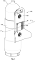
- FIG. 1 illustrates a back pack cinch 100 in a closed position and at least partially within a cavity 20 of a buoyancy compensation device 102, also referred to as a BC 102, to secure a breathing tank 104 to a diver (not illustrated) with a strap 116.
- the BC 102 may include a BC body 103 that may be a vest or back pack or in other forms commonly understood in the art. While a cavity 20 is illustrated it is not the intent to limit embodiments of a BC to only those having a cavity 20.
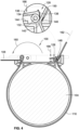
- FIG. 2 is a schematic cross section taken about line 2-2 of FIG. 1 of the back pack cinch 100 but with the back pack cinch 100 in the open position.
- the back pack cinch 100 includes a cinch body 106.
- Cinch body 106 may include a cover 108 that rotates at least partially around pivot pin 110.
- Pivot pin 110 may by entirely within cinch body 106 or in an embodiment may extend through the cinch body 106 to secure the back pack cinch 100 to the BC 102.
- the back pack cinch 100 may be permanently fixed in the BC 102 or in embodiments may be removable joined to the BC 102.
- the cinch body 106 may be a separate structure apart from the BC body 103 such that it can be "dropped in” or "snapped in” the BC 102.
- the cinch body 106 defines first aperture 112 and second aperture 114 for receiving a strap 116.
- the strap 116 may be a webbing or any suitable material known in the art of diving for securing a breathing tank 104 to a BC 102 and diver.
- a first end portion 118 of the strap 116 is fastened about a strap pin 120 of the cinch body 106 and exits out of the first aperture 112 to wrap circumferentially around the breathing tank 104.
- Securing of the first end portion 118 to the strap pin 120 may be done by any known method in the art including, by way of non-limiting examples, use of fasteners or stitching such that the first end portion 118 of the strap 116 is able to remain fixed in place at the first strap pin 120 when under tension to secure the breathing tank 104 to the BC 102.
- the back pack cinch 100 is shown in a first state, referred to as the open position.
- a top surface 122 of the cover 108 rests against a first stop 124 that may be provided by the BC 102.
- the cover 108 is also considered to be in an open position.
- the strap pin 120 rests within a second stop 126 ( FIG. 4 ) which is a groove that cooperates with the outer surface of the strap pin 120 to receive and bear against the outer surface of the strap pin 120 to act as a stop to prevent rotation of the back pack cinch 100 beyond what is shown in FIG. 2 .
- the cinch body 106 includes a tab 128 which includes a tab pin 132 to fasten the tab 128 to the cinch body 106.
- Tab 128 is arranged to rotate around the tab pin 132 within limits.
- the tab 128 includes a cam 134 and a lever 136.
- the lever 136 defines a planar surface sufficient to permit a diver and/or user to press the tab 128 in order to rotate the tab 128 about the tab pin 132 until it reaches a third stop 144 limit of the tab 128 as it rotates to an open position ( FIG. 4 ).
- the lever 136 further includes a toothed portion 138 that extends from a circumferential portion of the cam 134.
- the cam 134 further defines an outermost planar surface 140.
- the cam 134 may include the circumferential tooth portion 138 and the outermost planar surface 140 and the lever 136 which extends from the cam 134 such that a forces acting on the lever 136 may rotate the cam 134 and its toothed portion 138 and planar surfaces 140 between the closed and open state of the cam 134.
- the tab 128 is biased by a biasing member (not illustrated), in a first closed state referred to as a first closed position such that the toothed portion 138 of the cam 134 bears against a serrated bearing surface 146.
- the serrated bearing surface may be part of the cinch body 106 or in an embodiment part of the BC 102.
- the serrated bearing surface cooperates with the toothed portion 138 of the cam 134.
- the biasing member may be a spring such that the tab 128 may be considered a spring-loaded tab 128.
- the biasing member may a torsion spring surround tab pin 132 and acting on cam 134.
- the biasing member may be tension alone.
- FIG. 2 illustrates the back pack cinch 100 in an open position.
- the top surface 122 bears against the first stop 124
- the strap pin 120 is located in the second stop 126
- the tab 128 is in a first closed position such that the lever 136 is not resting against the third stop 144 and at least a first part of the toothed portion 138 of the tab 128 faces the serrated bearing surface 146 of the BC 102.
- the first end portion 118 of the strap 116 is secured around the strap pin 120.
- the strap 116 passes through the first aperture 112 through the BC 102 and circumferentially surrounds the breathing tank 104.
- Rotation of the lever 136 ( FIG. 4 ) towards the third stop 144, by pressing 166 the lever 136 tab 128 moves to the open position.
- a channel 148 FIG. 4
- a second end portion 150 is opened to allow a second end portion 150 to pass between the toothed portion 138 of the tab 128 and the serrated bearing surface 146 of the BC 102.
- tab 128 is free to rotate in the first direction to the first closed state such that the second end portion 150 of the strap 116 is sandwiched between a first part of the teeth of the first toothed portion 138 and the serrated bearing surface 146.
- the second end portion 150 of the strap 116 is then pulled in a first direction 152 to hand tighten the strap 116 to the breathing tank 104 as much as possible.
- the second end portion 150 of the strap may be let go of and the tab 128 is biased to rotate in the first direction closed to keep the second end portion 150 locked/fixed in place between the first toothed portion 128 and the serrated bearing surface 146.
- This self-locking function of the tab 128 prevents the strap 116 from moving a second direction, opposite the first direction.
- the self-locking function of the tab 128 keeps the strap 116 in a first state of tension, also referred to as pre-tensioned state to secure the breathing tank 104 to the BC 102.
- the self-locking tab 128 holds the strap 116 fixed in place between tab 128 and the serrated bearing surface 146.
- FIG. 3 illustrates the back pack cinch 100 and the cover 108 in the closed position.
- the cover 108 is rotated around pivot pin 110 towards the tab 128 in the first rotation direction shown by the large arrow 154.
- the strap pin 120 bears against a fourth stop 156 ( FIG. 3 ) defined by the cinch body 106.
- Rotating the cover 108 to the closed position creates a second tensioning force greater than the pre-tensioning force to secure the strap 120 tightly around the breathing tank 104 and the BC 102.
- the lever 136 rotates up and away from the third stop 144 such that a second part of the toothed portion 138 bear against the strap 116 when the back pack cinch 100 is fully closed such that pivot pin 120 bears against the fourth stop 156.
- the second part of the toothed portion 138 includes more teeth bearing against the serrated bearing surface 146 than when the first part of the toothed portion 138 bears against the strap 116 and the serrated bearing surface 146.
- the strap 116 In the closed position of the cover 108, the strap 116 is in a final tensioned state to fully secure the BC 102 to the breathing tank 104.
- the tension in the strap 116 at the tab 128 is such that the biasing force keeping the tab 128 closed/locked is greater than what it was before the cover 108 was closed.
- a bottom surface 158 of the cover 108 advantageously covers, and in doing so may be said to overlap at least an end 164 the tab 128 to prevent an unintentional release of the strap 116.
- the bottom surface 158 of the cover 108 faces and may even be in contact with the end 164 of the tab 128 and can be considered as a fifth stop preventing further rotation of the tab 128.
- the back pack cinch 100 is further protected from inadvertent openings because it rests between the BC 102 and the diver's back when the BC 102 is worn by a diver.
- the cover 108 of the back pack cinch 100 cannot rotate open fully as the diver's back acts as a stop to stop any cover rotation to open the back pack cinch 100.
- the over center rotation of the cover 108 to the closed position of the back pack cinch 100 keeps the cover 108 locked into the closed position without the need for any further structure on the BC 102 or back pack cinch 100 to keep the cover 108 closed. Further, a deliberate force by a user/diver is required to rotate the cover 108 back into the open position. Thus, the cover 108 in the closed position is not likely to open with an inadvertent blow/force such as incidental contact with another diver, by way of example. Further, even if an opening of the cover 108 were to occur such that the cover 108 moves back to its open position ( FIG. 2 ), as previously discussed, the tab 128 in its biased closed position which may also referred to as a second close position, keeps the strap 116 secured to the breathing tank 104 and BC 102.
- FIG. 4 is a second illustration of the back pack cinch 100 in the open position as in FIG. 3 .
- FIG. 4 further illustrates that in order to unthread the strap 116 from the back pack cinch 100, the cover 108 is rotated away from the tab 128 in a second rotational direction 160, opposite the first rotational direction 154 ( FIG. 4 ).
- the lever 136 of the tab 128 may be depressed in the direction 160 such that the channel 148 is defined by the planar portion 140 that is free of any teeth and the serrated bearing surface 146.
- the strap 116 is then free to be pulled in second pulling direction 162 opposite the first pulling direction 152 ( FIG. 3 ) to completely remove the strap 116 from back pack cinch 100 or to remove a portion of the strap 116 to loosen the strap 116 such that the breathing tank 104 may be easily removed from the BC 102.
Landscapes
- Engineering & Computer Science (AREA)
- General Engineering & Computer Science (AREA)
- Mechanical Engineering (AREA)
- Ocean & Marine Engineering (AREA)
- Health & Medical Sciences (AREA)
- General Health & Medical Sciences (AREA)
- Pulmonology (AREA)
- Respiratory Apparatuses And Protective Means (AREA)
- Portable Outdoor Equipment (AREA)
Description
- This invention generally relates to diving gear and more particularly to tank cinches for strapping down a breathing gas tank.
- In scuba diving, a diver uses a self-contained underwater breathing apparatus (scuba). Typically, scuba divers carry their own source of breathing gas, usually in a cylindrical tank, as part of their scuba gear. The tank is carried by the diver with the help of a buoyancy compensator, referred to as a BC. BC's may be a vest or back pack worn by the diver. The BC utilizes a strap, belt or webbing to secure the tank to the BC.
- Securing the tank to the BC is important in scuba diving. If the tank is not tightly connected to the BC then it can shift in position during the dive which could result in separation of the tank from the conduit supplying air to the diver. Further, if the connection of the tank to the BC is too loose or improperly done, the tank could separate from the BC which means it could fall off the diver. Such a fall, could prevent air from reaching the diver.
- Unfortunately, prior art cinch designs are complex, costly to manufacture and for divers not properly trained, hard to understand how to use. In other words, because the cinches of prior art designs are hard to understand and use, then divers are at risk of improperly securing their tanks to their BC's, which in turn could lead to the risks discussed above during a dive. Further, the physical location of prior art cinch designs may be subject to being opened inadvertently too easily such that the tanks they are securing being loose and causes the difficulties discussed above.
-
US 2009/0178256 A1 discloses a buckle assembly especially for use in securing gas cylinders such as scuba air tanks to a diver's backpack. -
US 2015/0191114 A1 presents a retaining mechanism for cinching a strap tightly against or around one or more items and a strap assembly including such a retaining mechanism. -
JP H02 25389 U -
JP 2000 104708 A -
US 2016/0360871 A1 discloses a clip for attaching auxiliary weight bearing items to a strap. - In one aspect, an embodiment of the invention provides a back pack cinch according to claim 1.
- In an embodiment, the cover in the closed state covers at least a portion of the tab.
- In an embodiment, the tab includes a lever. An end of the lever is covered at least partially by the cover in the closed position of the cover and uncovered in the open position of the cover.
- In an embodiment, the tab includes a lever having a toothed portion and a cam having a planar portion.
- In an embodiment, the tab is biased closed when the cover is in the open position and in the closed position.
- In an embodiment, the cam is biased to move in the first rotational direction to close the tab and second rotational direction, opposite the first rotational direction to open the tab.
- In an embodiment, the tab is arranged to define a channel between the planar portion of the cam and the serrated bearing surface when the tab is rotated in the second rotational direction, opposite the first rotational direction.
- In an embodiment, in the open state of the cover, a first part of the tooth portion of the tab is biased to bear against the strap of the bouncy compensation device to sandwich the strap between the first part of the tooth portion and a serrated bearing surface.
- In an embodiment, during transition from the open state to the closed state of the cover, the tab rotates in the first rotational direction and a second part of the toothed portion of the tab faces the serrated bearing surface of the buoyancy compensation device. The second part includes at least the first part.
- In an embodiment, in the closed state the cover of the cinch body is between a back of the diver and the buoyancy compensation device.
- In an embodiment, the tab is biased to rotate in a first rotational direction to fix the strap between the toothed portion of the cam and a serrated bearing surface and in a second rotational direction opposite the first rotational direction to open a channel defined between the planar portion of the cam and the serrated bearing surface.
- In an embodiment, the strap remains fixed between the toothed portion of the cam and the serrated bearing surface when the cover is pivoted between the open position and the closed position and between the closed position and the open position.
- In an embodiment, the tab remains in the closed position when the cover is rotated from the closed position to the open position.
- In an embodiment, the tab includes a cam having a toothed portion and a planar portion, the tab biased to have the toothed portion bear against the strap and a cooperating serrated bearing surface to fix the second end portion of the strap in place.
- In still another aspect, an embodiment of the invention provides a buoyancy compensation device according to claim 11.
- In an embodiment, when the buoyancy compensation body is worn by a diver, the cover lies between the diver's back and an area of the breathing tank nearest the diver's back.
- In an embodiment, the cover includes a strap pin to fix the first end portion of the strap. The second end portion of the strap is fixed between the toothed portion and the serrated bearing surface and the first end is fixed to the strap pin. Rotation of the cover about the pivot pin towards the tab rotates the tab in the first direction towards the serrated bearing surface to tension the strap.
- In an embodiment, the tab is configured to rotate in a second direction, opposite the first direction, when the second end portion of the strap is pulled in a direction away from the breathing tank.
- In an embodiment, the tab includes a lever. The lever is arranged to rotate the cam in a second direction, opposite the first direction, when a force is applied on the lever in a direction towards the underwater breathing tank.
- Other aspects, objectives and advantages of embodiments of the invention will become more apparent from the following detailed description when taken in conjunction with the accompanying drawings.
- The accompanying drawings incorporated in and forming a part of the specification illustrate several aspects of embodiments of the present invention and, together with the description, serve to explain the principles of the invention. In the drawings:
-
FIG. 1 is a perspective view of a back pack cinch in a closed position securing a buoyancy compensation device to a breathing tank with a strap; -
FIG. 2 a schematic cross section taken about line 2-2 ofFIG. 1 but with the back pack cinch in an open position with a tab in a closed positon according to the teachings of the instant invention; -
FIG. 3 illustrates a schematic cross section of the back pack cinch ofFIG. 1 with the back pack cinch in a closed position; and -
FIG. 4 illustrates the schematic cross section of the back pack cinch ofFIG. 2 with the tab in an open position. - While embodiments of the invention will be described in connection with certain preferred embodiments, there is no intent to limit it to those embodiments. On the contrary, the intent is to cover all alternatives, modifications and equivalents as included within the scope of the invention as defined by the appended claims.
- Embodiments of the invention provide back pack cinch that quickly and safely pre-tensions a strap to secure a breathing tank to a buoyancy compensator device, also referred to as a BC, before a final tensioning is provided by the back pack cinch. BC's may be a vest or back pack worn by the diver as readily understood by those familiar with the art. These and other advantages of the invention, as well as additional inventive features, will be apparent from the description of the invention provided herein.
-
FIG. 1 illustrates aback pack cinch 100 in a closed position and at least partially within acavity 20 of abuoyancy compensation device 102, also referred to as aBC 102, to secure abreathing tank 104 to a diver (not illustrated) with astrap 116. TheBC 102 may include aBC body 103 that may be a vest or back pack or in other forms commonly understood in the art. While acavity 20 is illustrated it is not the intent to limit embodiments of a BC to only those having acavity 20. -
FIG. 2 is a schematic cross section taken about line 2-2 ofFIG. 1 of theback pack cinch 100 but with theback pack cinch 100 in the open position. Theback pack cinch 100 includes acinch body 106.Cinch body 106 may include acover 108 that rotates at least partially aroundpivot pin 110.Pivot pin 110 may by entirely withincinch body 106 or in an embodiment may extend through thecinch body 106 to secure theback pack cinch 100 to theBC 102. Theback pack cinch 100 may be permanently fixed in theBC 102 or in embodiments may be removable joined to theBC 102. Further, thecinch body 106 may be a separate structure apart from theBC body 103 such that it can be "dropped in" or "snapped in" theBC 102. - The
cinch body 106 definesfirst aperture 112 andsecond aperture 114 for receiving astrap 116. Thestrap 116, may be a webbing or any suitable material known in the art of diving for securing abreathing tank 104 to aBC 102 and diver. - A
first end portion 118 of thestrap 116 is fastened about astrap pin 120 of thecinch body 106 and exits out of thefirst aperture 112 to wrap circumferentially around thebreathing tank 104. Securing of thefirst end portion 118 to thestrap pin 120 may be done by any known method in the art including, by way of non-limiting examples, use of fasteners or stitching such that thefirst end portion 118 of thestrap 116 is able to remain fixed in place at thefirst strap pin 120 when under tension to secure thebreathing tank 104 to theBC 102. - The
back pack cinch 100 is shown in a first state, referred to as the open position. When theback pack cinch 100 is open, atop surface 122 of thecover 108 rests against afirst stop 124 that may be provided by theBC 102. Thus, thecover 108 is also considered to be in an open position. Thestrap pin 120 rests within a second stop 126 (FIG. 4 ) which is a groove that cooperates with the outer surface of thestrap pin 120 to receive and bear against the outer surface of thestrap pin 120 to act as a stop to prevent rotation of theback pack cinch 100 beyond what is shown inFIG. 2 . - The
cinch body 106 includes atab 128 which includes atab pin 132 to fasten thetab 128 to thecinch body 106.Tab 128 is arranged to rotate around thetab pin 132 within limits. Thetab 128 includes acam 134 and alever 136. Thelever 136 defines a planar surface sufficient to permit a diver and/or user to press thetab 128 in order to rotate thetab 128 about thetab pin 132 until it reaches athird stop 144 limit of thetab 128 as it rotates to an open position (FIG. 4 ). Thelever 136 further includes atoothed portion 138 that extends from a circumferential portion of thecam 134. Thecam 134 further defines an outermostplanar surface 140. - The
cam 134 may include thecircumferential tooth portion 138 and the outermostplanar surface 140 and thelever 136 which extends from thecam 134 such that a forces acting on thelever 136 may rotate thecam 134 and itstoothed portion 138 andplanar surfaces 140 between the closed and open state of thecam 134. - The
tab 128 is biased by a biasing member (not illustrated), in a first closed state referred to as a first closed position such that thetoothed portion 138 of thecam 134 bears against aserrated bearing surface 146. The serrated bearing surface may be part of thecinch body 106 or in an embodiment part of theBC 102. The serrated bearing surface cooperates with thetoothed portion 138 of thecam 134. Thus, inFIG. 2 it can be appreciated that thetab 128 is biased to rotate in a first direction to keep thetab 128 in a first closed position. The biasing member may be a spring such that thetab 128 may be considered a spring-loadedtab 128. For example, the biasing member may a torsion springsurround tab pin 132 and acting oncam 134. Alternatively, the biasing member may be tension alone. -
FIG. 2 illustrates theback pack cinch 100 in an open position. Thetop surface 122 bears against thefirst stop 124, thestrap pin 120 is located in thesecond stop 126, thetab 128 is in a first closed position such that thelever 136 is not resting against thethird stop 144 and at least a first part of thetoothed portion 138 of thetab 128 faces theserrated bearing surface 146 of theBC 102. - In order to secure the
breathing tank 104 to theBC 102 using theback pack cinch 100, thefirst end portion 118 of thestrap 116 is secured around thestrap pin 120. Thestrap 116 passes through thefirst aperture 112 through theBC 102 and circumferentially surrounds thebreathing tank 104. Rotation of the lever 136 (FIG. 4 ) towards thethird stop 144, by pressing 166 thelever 136tab 128 moves to the open position. As thetab 128 moves to the open position a channel 148 (FIG. 4 ) is opened to allow asecond end portion 150 to pass between thetoothed portion 138 of thetab 128 and theserrated bearing surface 146 of theBC 102. Even if thelever 136 is not pressed, an effort to push thestrap 116 in a direction extending away from thebreathing tank 104 and thesecond aperture 114 and between thetooth portion 138 of thetab 128 and theserrated bearing surface 146 may be sufficient to rotate thetab 128 to the open position to allow thestrap 116 to pass between thetoothed portion 138 and theserrated bearing surface 146. - Once the
strap 116 is in place and there is no force action on thelever 136,tab 128 is free to rotate in the first direction to the first closed state such that thesecond end portion 150 of thestrap 116 is sandwiched between a first part of the teeth of the firsttoothed portion 138 and theserrated bearing surface 146. Thesecond end portion 150 of thestrap 116 is then pulled in afirst direction 152 to hand tighten thestrap 116 to thebreathing tank 104 as much as possible. Once the pulling force is stopped thesecond end portion 150 of the strap may be let go of and thetab 128 is biased to rotate in the first direction closed to keep thesecond end portion 150 locked/fixed in place between the firsttoothed portion 128 and theserrated bearing surface 146. This self-locking function of thetab 128 prevents thestrap 116 from moving a second direction, opposite the first direction. Thus, the self-locking function of thetab 128 keeps thestrap 116 in a first state of tension, also referred to as pre-tensioned state to secure thebreathing tank 104 to theBC 102. Thus, the self-lockingtab 128 holds thestrap 116 fixed in place betweentab 128 and theserrated bearing surface 146. -
FIG. 3 illustrates theback pack cinch 100 and thecover 108 in the closed position. To rotate theback pack cinch 100 to the closed position, thecover 108 is rotated aroundpivot pin 110 towards thetab 128 in the first rotation direction shown by thelarge arrow 154. In the closed position ofback pack cinch 100, thestrap pin 120 bears against a fourth stop 156 (FIG. 3 ) defined by thecinch body 106. Rotating thecover 108 to the closed position creates a second tensioning force greater than the pre-tensioning force to secure thestrap 120 tightly around thebreathing tank 104 and theBC 102. - During the rotation of the
cover 108 to the closed position and in the closed position of thecover 108 and thus theback pack cinch 100, thelever 136 rotates up and away from thethird stop 144 such that a second part of thetoothed portion 138 bear against thestrap 116 when theback pack cinch 100 is fully closed such thatpivot pin 120 bears against thefourth stop 156. The second part of thetoothed portion 138 includes more teeth bearing against theserrated bearing surface 146 than when the first part of thetoothed portion 138 bears against thestrap 116 and theserrated bearing surface 146. - In the closed position of the
cover 108, thestrap 116 is in a final tensioned state to fully secure theBC 102 to thebreathing tank 104. The tension in thestrap 116 at thetab 128 is such that the biasing force keeping thetab 128 closed/locked is greater than what it was before thecover 108 was closed. - In the closed position of the
cover 108, abottom surface 158 of thecover 108 advantageously covers, and in doing so may be said to overlap at least anend 164 thetab 128 to prevent an unintentional release of thestrap 116. Thus, thebottom surface 158 of thecover 108 faces and may even be in contact with theend 164 of thetab 128 and can be considered as a fifth stop preventing further rotation of thetab 128. It can also now be readily understood that theback pack cinch 100 is further protected from inadvertent openings because it rests between theBC 102 and the diver's back when theBC 102 is worn by a diver. Thus, thecover 108 of theback pack cinch 100 cannot rotate open fully as the diver's back acts as a stop to stop any cover rotation to open theback pack cinch 100. - As can now be appreciated, the over center rotation of the
cover 108 to the closed position of theback pack cinch 100 keeps thecover 108 locked into the closed position without the need for any further structure on theBC 102 or backpack cinch 100 to keep thecover 108 closed. Further, a deliberate force by a user/diver is required to rotate thecover 108 back into the open position. Thus, thecover 108 in the closed position is not likely to open with an inadvertent blow/force such as incidental contact with another diver, by way of example. Further, even if an opening of thecover 108 were to occur such that thecover 108 moves back to its open position (FIG. 2 ), as previously discussed, thetab 128 in its biased closed position which may also referred to as a second close position, keeps thestrap 116 secured to thebreathing tank 104 andBC 102. -
FIG. 4 is a second illustration of theback pack cinch 100 in the open position as inFIG. 3 . However,FIG. 4 further illustrates that in order to unthread thestrap 116 from theback pack cinch 100, thecover 108 is rotated away from thetab 128 in a secondrotational direction 160, opposite the first rotational direction 154 (FIG. 4 ). Once thecover 108 is in the open state, thelever 136 of thetab 128 may be depressed in thedirection 160 such that thechannel 148 is defined by theplanar portion 140 that is free of any teeth and theserrated bearing surface 146. Thestrap 116 is then free to be pulled in second pullingdirection 162 opposite the first pulling direction 152 (FIG. 3 ) to completely remove thestrap 116 fromback pack cinch 100 or to remove a portion of thestrap 116 to loosen thestrap 116 such that thebreathing tank 104 may be easily removed from theBC 102. - The use of the terms "a" and "an" and "the" and similar referents in the context of describing the invention (especially in the context of the following claims) is to be construed to cover both the singular and the plural, unless otherwise indicated herein or clearly contradicted by context. The terms "comprising," "having," "including," and "containing" are to be construed as open-ended terms (i.e., meaning "including, but not limited to,") unless otherwise noted. Recitation of ranges of values herein are merely intended to serve as a shorthand method of referring individually to each separate value falling within the range, unless otherwise indicated herein, and each separate value is incorporated into the specification as if it were individually recited herein. All methods described herein can be performed in any suitable order unless otherwise indicated herein or otherwise clearly contradicted by context. The use of any and all examples, or exemplary language (e.g., "such as") provided herein, is intended merely to better illuminate the invention and does not pose a limitation on the scope of the invention unless otherwise claimed. No language in the specification should be construed as indicating any non-claimed element as essential to the practice of the invention.
- Preferred embodiments of this invention are described herein, including the best mode known to the inventors for carrying out the invention. Variations of those preferred embodiments may become apparent to those of ordinary skill in the art upon reading the foregoing description. The inventors expect skilled artisans to employ such variations as appropriate, and the inventors intend for the invention to be practiced otherwise than as specifically described herein. Accordingly, this invention includes all modifications and equivalents of the subject matter recited in the claims appended hereto as permitted by applicable law. Moreover, any combination of the above-described elements in all possible variations thereof is encompassed by the invention unless otherwise indicated herein or otherwise clearly contradicted by context.
Claims (15)
- A back pack cinch (100) for a strap (116) securing a breathing tank (104) to a buoyancy compensation device (102) worn by a diver, the back pack cinch (100) comprising:a cinch body (106) having a serrated bearing surface (146);a cover (108) rotatably mounted to the cinch body (106), the cover (108) having an open position and a closed position, wherein in the closed position, the cover (108) is configured to tension a strap (116); anda tab (128) rotatably mounted to the cinch body (106), the tab(128) having an open position and a closed position, wherein in the closed position, a portion of the strap (116) is pressed against the serrated bearing surface (146) by the tab (128) to hold the portion of the strap (116) in a fixed position.
- The back pack cinch (100) of claim 1, wherein the cover (108) in the closed position, covers at least a portion of the tab (128).
- The back pack cinch (100) of claim 2, wherein the tab (128) includes a lever (136), an end of the lever (136) covered at least partially by the cover (108) in the closed position of the cover (108) and uncovered in the open position of the cover (108), wherein optionally the tab (128) is biased closed when the cover (108) is in the open position and in the closed position.
- The back pack cinch (100) of claim 1, wherein the tab (128) includes a lever (136) having a toothed portion (138) and a cam (134) having a planar portion (140).
- The back pack cinch (100) of claim 4, wherein the cam (134) is biased to move in a first rotational direction (154) to close the tab (128) and in a second rotational direction (160), opposite the first rotational direction (154) to open the tab (128), wherein optionally the tab (128) is arranged to define a channel (148) between a planar portion (140) of the cam (134) and the serrated bearing surface (146) when the tab (128) is rotated in the second rotational direction (160), opposite the first rotational direction (154).
- The back pack cinch (100) of claim 4, wherein in the open position of the cover (108) a first part of the toothed portion (138) of the tab (128) is biased to bear against the strap (116) of the buoyancy compensation device (102) to sandwich the strap (116) between the first part of the toothed portion (138) and the serrated bearing surface (146), wherein optionally during transition from the open position to the closed position of the cover (108), the tab (128) rotates in a first rotational direction (154) and a second part of the toothed portion (138) of the tab (128) faces the serrated bearing surface (146) of the buoyancy compensation device (102) and wherein the second part includes at least the first part.
- The back pack cinch (100) of claim 2, wherein in the closed position the cover (108) is between a back of the diver and the buoyancy compensation device (102).
- The back pack cinch (100) of claim 2, wherein the cover (108) is arranged to rotate about a pivot pin (110) between the open position and the closed position; and wherein the tab (128) has a cam (134) with a toothed portion (138) and a planar portion (140).
- The back pack cinch (100) of claim 8, wherein the tab (128) is biased to rotate in a first rotational direction (154) to fix the strap (116) between the toothed portion (138) of the cam (134) and the serrated bearing surface (146) and in a second rotational direction (160) opposite the first rotational direction (154) to open a channel (148) defined between the planar portion (140) of the cam (134) and the serrated bearing surface (146).
- The back pack cinch (100) of claim 8, wherein the strap (116) remains fixed between the toothed portion (138) of the cam (134) and the serrated bearing surface (146) when the cover (108) is pivoted between the open position and the closed position and between the closed position and the open position.
- A buoyancy compensation device (102) configured to secure a breathing tank (104); the buoyancy compensation device (102) comprising:a buoyancy compensation body (103) configured to be worn by a diver;a strap (116) arranged to surround the breathing tank (104) and at least a part of the buoyancy compensation body (103);a back pack tank cinch (100) having a cinch body (106) configured to receive a first end portion (118) of the strap (116) and a second end portion (150) of the strap (116) to secure the breathing tank (104) to the buoyancy compensation device (102);a cover (108) rotatably mounted to the cinch body (106), the cover (108) having an open position and a closed position, wherein in the closed position, the cover (108) is configured to tension the strap (116); anda tab (128) rotatably mounted to the cinch body (106), the tab (128) having an open position and a closed position,wherein the cover (108) in the closed position overlaps at least a portion of the tab (128),wherein one of the cinch body (106) and buoyancy compensation device (102) provides a serrated bearing surface (146),wherein the tab (128) includes a cam (134) having a toothed portion (138) and a planar portion (140), the tab (128) biased to have the toothed portion (138) bear against the strap (116) and the cooperating serrated bearing surface (146) to fix the second end portion (150) of the strap (116) in place.
- The buoyancy compensation device (102) of claim 11, wherein the tab (128) remains in the closed position when the cover (108) is rotated from the closed position to the open position, wherein optionally when the buoyancy compensation body (103) is worn by the diver, the cover (108) lies between the diver's back and an area of the breathing tank (104) nearest the diver's back.
- The buoyancy compensation device (102) of claim 11, wherein the cover (108) includes a strap pin (120) to fix the first end portion (118) of the strap (116), wherein when the second end portion (150) is fixed between the toothed portion (138) and the serrated bearing surface (146) and the first end portion (118) is fixed to the strap pin (120), rotation of the cover (108) about the pivot pin (110) towards the tab (128) rotates the tab (128) in a first direction towards the serrated bearing surface (146) to tension the strap (116).
- The buoyancy compensation device (102) of claim 13, wherein the tab (128) is configured to rotate in a second direction, opposite the first direction, when the second end portion (150) of the strap (116) is pulled in a direction away from the breathing tank (104).
- The buoyancy compensation device (102) of claim 13, wherein the tab (128) includes a lever (136), the lever (136) arranged to rotate the cam (134) in a second direction, opposite the first direction, when a force is applied on the lever (136) in a direction towards the underwater breathing tank (104).
Applications Claiming Priority (3)
| Application Number | Priority Date | Filing Date | Title |
|---|---|---|---|
| US201762562808P | 2017-09-25 | 2017-09-25 | |
| US16/137,188 US10717507B2 (en) | 2017-09-25 | 2018-09-20 | Back pack cinch and buoyancy compensation device |
| PCT/US2018/052426 WO2019060828A1 (en) | 2017-09-25 | 2018-09-24 | Back pack cinch |
Publications (3)
| Publication Number | Publication Date |
|---|---|
| EP3687893A1 EP3687893A1 (en) | 2020-08-05 |
| EP3687893A4 EP3687893A4 (en) | 2021-06-16 |
| EP3687893B1 true EP3687893B1 (en) | 2025-02-12 |
Family
ID=65808882
Family Applications (1)
| Application Number | Title | Priority Date | Filing Date |
|---|---|---|---|
| EP18857589.8A Active EP3687893B1 (en) | 2017-09-25 | 2018-09-24 | Back pack cinch |
Country Status (4)
| Country | Link |
|---|---|
| US (1) | US10717507B2 (en) |
| EP (1) | EP3687893B1 (en) |
| DE (1) | DE202018006524U1 (en) |
| WO (1) | WO2019060828A1 (en) |
Families Citing this family (8)
| Publication number | Priority date | Publication date | Assignee | Title |
|---|---|---|---|---|
| US20150217154A1 (en) * | 2014-02-06 | 2015-08-06 | Performance Advantage Company, Inc. | Universal nozzle connector with an adjustable mount |
| GB2573332B (en) * | 2018-05-04 | 2022-05-04 | Draeger Safety Uk Ltd | Back plate for a breathing apparatus |
| US20200383866A1 (en) * | 2019-06-06 | 2020-12-10 | Alan Scott Crarer | Therapeutic Roller Bracing System |
| USD1005431S1 (en) * | 2019-09-20 | 2023-11-21 | Rhys James Couzyn | Scuba diving backplate |
| WO2021084484A2 (en) * | 2019-10-29 | 2021-05-06 | Stryker European Operations Limited | Surgical navigation tracker, system, and method |
| GB2589923B (en) * | 2019-12-13 | 2021-12-08 | Three Smith Group Ltd | Strapping apparatus |
| EP4292668A1 (en) * | 2022-06-16 | 2023-12-20 | Dräger Safety AG & Co. KGaA | Support frame for a breathing apparatus |
| USD1100185S1 (en) * | 2023-01-19 | 2025-10-28 | Xdeep Sp. Z O.O. Sp.K. | Diving apparatus |
Family Cites Families (35)
| Publication number | Priority date | Publication date | Assignee | Title |
|---|---|---|---|---|
| US3033431A (en) | 1960-08-08 | 1962-05-08 | Robert B Henderson | Back plate for self-contained underwater breathing apparatus |
| US3957183A (en) | 1974-03-14 | 1976-05-18 | U.S. Divers Company | Backpack for breathing tanks |
| US4310110A (en) | 1980-01-21 | 1982-01-12 | Under Sea Industries, Inc. | Scuba tank harness |
| US4690314A (en) | 1985-08-26 | 1987-09-01 | Mark Faulconer | Buoyancy compensator insertable backpack |
| CH668168A5 (en) * | 1986-04-25 | 1988-12-15 | Lange Int Sa | DEVICE FOR CLOSING A SHOE. |
| US4778307A (en) | 1986-12-23 | 1988-10-18 | U.S. Divers Company | Buoyancy compensator with an adjustable strap |
| JP2933934B2 (en) * | 1988-07-15 | 1999-08-16 | 株式会社リコー | Sublimation type thermal transfer recording medium |
| JPH0225389U (en) | 1988-08-08 | 1990-02-20 | ||
| US5046894A (en) | 1990-07-12 | 1991-09-10 | Soniform, Inc. | Buoyancy compensator with interchangeable backpack and commerbund |
| US5378084A (en) | 1991-11-18 | 1995-01-03 | Walters; William D. | Backpack systems |
| US5346419A (en) | 1993-05-14 | 1994-09-13 | International Divers Inc. | Buoyancy compensator device with backpack and adjustable harness |
| US5522679A (en) | 1994-06-02 | 1996-06-04 | Dacor Corporation | Buoyancy compensator having attached backpack |
| US5567084A (en) | 1995-02-24 | 1996-10-22 | Sea Quest, Inc. | Buoyancy compensator with a traction pressure pad |
| US5662433A (en) | 1995-10-17 | 1997-09-02 | Sea Quest, Inc. | Body conforming vest, buoyancy compensator, and backpack |
| US5626439A (en) | 1995-12-07 | 1997-05-06 | Rowlands; Albert J. | Diver's vest having compressed air tightening device |
| JP2000104708A (en) * | 1998-09-29 | 2000-04-11 | Hashi:Kk | Improved cam buckle |
| IT248403Y1 (en) | 1999-07-28 | 2003-01-28 | Htm Sport Spa | BACKREST FOR CYLINDERS FOR DIVING |
| US6402429B1 (en) | 1999-08-20 | 2002-06-11 | Zeagle Systems, Inc. | Buoyancy compensator harness system |
| US20020009335A1 (en) | 2000-07-18 | 2002-01-24 | Courtney William L. | Vertically eccentric, horizontally symmetric, mobile and fixed buoyant in combination with mobile and fixed ballast as a type a personal flotation device |
| JP3771447B2 (en) | 2001-01-16 | 2006-04-26 | 株式会社タバタ | Diving jacket |
| WO2004056651A2 (en) | 2002-12-17 | 2004-07-08 | Sharkbait, Llc | Mounting system |
| US6749370B1 (en) | 2003-03-11 | 2004-06-15 | Tabata Co., Ltd. | Buoyancy compensating jacket |
| JP3994080B2 (en) | 2003-10-06 | 2007-10-17 | 株式会社タバタ | Cylinder fixing device |
| US7367749B2 (en) | 2003-11-19 | 2008-05-06 | Sancheong Co. Ltd. | Backpack |
| JP4253624B2 (en) | 2004-08-12 | 2009-04-15 | 株式会社タバタ | Cylinder band of buoyancy regulator |
| US7052211B1 (en) | 2005-05-06 | 2006-05-30 | Curry Michael B | Buoyancy compensating device protective cover |
| US7540690B2 (en) | 2005-10-03 | 2009-06-02 | G Albert Hreish | Adjustable size buoyancy compensator |
| US8006877B2 (en) | 2007-04-18 | 2011-08-30 | Sperian Respiratory Protection Usa, Llc | Backpack for self contained breathing apparatus |
| US20110197406A1 (en) | 2007-08-10 | 2011-08-18 | Rhys James Couzyn | Securing arrangement for securing a diving cylinder to a buoyancy control device |
| US20090178256A1 (en) | 2008-01-11 | 2009-07-16 | Toth Douglas J | Ratcheting adjustable tank band and buckle assembly for securing gas cylinders to backpacks |
| GB2470023B (en) | 2009-05-06 | 2015-03-18 | Draeger Safety Uk Ltd | Gas-cylinder retaining assembly |
| US8398337B2 (en) | 2009-06-05 | 2013-03-19 | Halcyon Manufacturing, Inc. | Continuous weave quick harness backplate system |
| US9586065B2 (en) | 2013-11-27 | 2017-03-07 | Msa Technology, Llc | Modular tank cradle and backpack for self-contained breathing apparatus |
| US20150191114A1 (en) * | 2014-01-05 | 2015-07-09 | Outdoor Technology Group, Llc | Strap-retaining mechanism and strap assembly containing same |
| US10085544B2 (en) * | 2015-06-15 | 2018-10-02 | Larry Edward Schessel | Clip and method for attaching an item to a strap worn by a person |
-
2018
- 2018-09-20 US US16/137,188 patent/US10717507B2/en active Active
- 2018-09-24 EP EP18857589.8A patent/EP3687893B1/en active Active
- 2018-09-24 DE DE202018006524.2U patent/DE202018006524U1/en active Active
- 2018-09-24 WO PCT/US2018/052426 patent/WO2019060828A1/en not_active Ceased
Also Published As
| Publication number | Publication date |
|---|---|
| US20190092439A1 (en) | 2019-03-28 |
| EP3687893A4 (en) | 2021-06-16 |
| DE202018006524U1 (en) | 2021-01-21 |
| WO2019060828A1 (en) | 2019-03-28 |
| US10717507B2 (en) | 2020-07-21 |
| EP3687893A1 (en) | 2020-08-05 |
Similar Documents
| Publication | Publication Date | Title |
|---|---|---|
| US10717507B2 (en) | Back pack cinch and buoyancy compensation device | |
| US20090178256A1 (en) | Ratcheting adjustable tank band and buckle assembly for securing gas cylinders to backpacks | |
| US7600660B2 (en) | Harness tightening system | |
| CN104270984B (en) | System and method for keeping flat band | |
| US5816185A (en) | Ratcheting means for quickly securing a cover over a boat and the method of using the same | |
| US20160257379A1 (en) | Hinge with securing features | |
| US10772389B2 (en) | Quick fit tank cinch | |
| EP4023543B1 (en) | Back pack for underwater breathing tank | |
| MX2015002849A (en) | Strap tensioning system. | |
| US20110197406A1 (en) | Securing arrangement for securing a diving cylinder to a buoyancy control device | |
| US6293215B1 (en) | Sailing harness | |
| EP4334601B1 (en) | Dual hook flat strap attachment device | |
| NO340885B1 (en) | Winding apparatus for a band-shaped element | |
| US20250010769A1 (en) | Child seat harness tightening mechanism | |
| US9987969B1 (en) | Vehicle integrated fastening system | |
| KR101954091B1 (en) | Side mount type scuba tank holding band | |
| US20240199160A1 (en) | Tilting Vehicle With a Luggage Fastening Device | |
| HK40001924A (en) | Quick fit tank cinch | |
| US3734365A (en) | Back pack and fastener | |
| HK40001924B (en) | Quick fit tank cinch | |
| US8371656B2 (en) | Portable safety belt | |
| US20260068998A1 (en) | Strap Tensioner and Tension Indicator | |
| EP4450864B1 (en) | Protection device and method for gas container tap, system equipped with such a device | |
| JP7234473B1 (en) | Conveyor | |
| FR3124687A1 (en) | Closing device and method and helmet comprising such a closing device |
Legal Events
| Date | Code | Title | Description |
|---|---|---|---|
| STAA | Information on the status of an ep patent application or granted ep patent |
Free format text: STATUS: THE INTERNATIONAL PUBLICATION HAS BEEN MADE |
|
| PUAI | Public reference made under article 153(3) epc to a published international application that has entered the european phase |
Free format text: ORIGINAL CODE: 0009012 |
|
| STAA | Information on the status of an ep patent application or granted ep patent |
Free format text: STATUS: REQUEST FOR EXAMINATION WAS MADE |
|
| 17P | Request for examination filed |
Effective date: 20200417 |
|
| AK | Designated contracting states |
Kind code of ref document: A1 Designated state(s): AL AT BE BG CH CY CZ DE DK EE ES FI FR GB GR HR HU IE IS IT LI LT LU LV MC MK MT NL NO PL PT RO RS SE SI SK SM TR |
|
| AX | Request for extension of the european patent |
Extension state: BA ME |
|
| DAV | Request for validation of the european patent (deleted) | ||
| DAX | Request for extension of the european patent (deleted) | ||
| A4 | Supplementary search report drawn up and despatched |
Effective date: 20210514 |
|
| RIC1 | Information provided on ipc code assigned before grant |
Ipc: B63C 11/22 20060101AFI20210508BHEP |
|
| STAA | Information on the status of an ep patent application or granted ep patent |
Free format text: STATUS: EXAMINATION IS IN PROGRESS |
|
| 17Q | First examination report despatched |
Effective date: 20230904 |
|
| GRAP | Despatch of communication of intention to grant a patent |
Free format text: ORIGINAL CODE: EPIDOSNIGR1 |
|
| STAA | Information on the status of an ep patent application or granted ep patent |
Free format text: STATUS: GRANT OF PATENT IS INTENDED |
|
| INTG | Intention to grant announced |
Effective date: 20240613 |
|
| GRAJ | Information related to disapproval of communication of intention to grant by the applicant or resumption of examination proceedings by the epo deleted |
Free format text: ORIGINAL CODE: EPIDOSDIGR1 |
|
| STAA | Information on the status of an ep patent application or granted ep patent |
Free format text: STATUS: EXAMINATION IS IN PROGRESS |
|
| GRAP | Despatch of communication of intention to grant a patent |
Free format text: ORIGINAL CODE: EPIDOSNIGR1 |
|
| STAA | Information on the status of an ep patent application or granted ep patent |
Free format text: STATUS: GRANT OF PATENT IS INTENDED |
|
| INTC | Intention to grant announced (deleted) | ||
| INTG | Intention to grant announced |
Effective date: 20240904 |
|
| GRAS | Grant fee paid |
Free format text: ORIGINAL CODE: EPIDOSNIGR3 |
|
| GRAA | (expected) grant |
Free format text: ORIGINAL CODE: 0009210 |
|
| STAA | Information on the status of an ep patent application or granted ep patent |
Free format text: STATUS: THE PATENT HAS BEEN GRANTED |
|
| P01 | Opt-out of the competence of the unified patent court (upc) registered |
Free format text: CASE NUMBER: APP_66706/2024 Effective date: 20241217 |
|
| AK | Designated contracting states |
Kind code of ref document: B1 Designated state(s): AL AT BE BG CH CY CZ DE DK EE ES FI FR GB GR HR HU IE IS IT LI LT LU LV MC MK MT NL NO PL PT RO RS SE SI SK SM TR |
|
| REG | Reference to a national code |
Ref country code: GB Ref legal event code: FG4D |
|
| REG | Reference to a national code |
Ref country code: CH Ref legal event code: EP |
|
| REG | Reference to a national code |
Ref country code: DE Ref legal event code: R096 Ref document number: 602018079159 Country of ref document: DE |
|
| REG | Reference to a national code |
Ref country code: IE Ref legal event code: FG4D |
|
| REG | Reference to a national code |
Ref country code: NL Ref legal event code: MP Effective date: 20250212 |
|
| PG25 | Lapsed in a contracting state [announced via postgrant information from national office to epo] |
Ref country code: RS Free format text: LAPSE BECAUSE OF FAILURE TO SUBMIT A TRANSLATION OF THE DESCRIPTION OR TO PAY THE FEE WITHIN THE PRESCRIBED TIME-LIMIT Effective date: 20250512 |
|
| PG25 | Lapsed in a contracting state [announced via postgrant information from national office to epo] |
Ref country code: FI Free format text: LAPSE BECAUSE OF FAILURE TO SUBMIT A TRANSLATION OF THE DESCRIPTION OR TO PAY THE FEE WITHIN THE PRESCRIBED TIME-LIMIT Effective date: 20250212 |
|
| PG25 | Lapsed in a contracting state [announced via postgrant information from national office to epo] |
Ref country code: PL Free format text: LAPSE BECAUSE OF FAILURE TO SUBMIT A TRANSLATION OF THE DESCRIPTION OR TO PAY THE FEE WITHIN THE PRESCRIBED TIME-LIMIT Effective date: 20250212 |
|
| PG25 | Lapsed in a contracting state [announced via postgrant information from national office to epo] |
Ref country code: ES Free format text: LAPSE BECAUSE OF FAILURE TO SUBMIT A TRANSLATION OF THE DESCRIPTION OR TO PAY THE FEE WITHIN THE PRESCRIBED TIME-LIMIT Effective date: 20250212 |
|
| REG | Reference to a national code |
Ref country code: LT Ref legal event code: MG9D |
|
| PG25 | Lapsed in a contracting state [announced via postgrant information from national office to epo] |
Ref country code: IS Free format text: LAPSE BECAUSE OF FAILURE TO SUBMIT A TRANSLATION OF THE DESCRIPTION OR TO PAY THE FEE WITHIN THE PRESCRIBED TIME-LIMIT Effective date: 20250612 Ref country code: NO Free format text: LAPSE BECAUSE OF FAILURE TO SUBMIT A TRANSLATION OF THE DESCRIPTION OR TO PAY THE FEE WITHIN THE PRESCRIBED TIME-LIMIT Effective date: 20250512 |
|
| PG25 | Lapsed in a contracting state [announced via postgrant information from national office to epo] |
Ref country code: NL Free format text: LAPSE BECAUSE OF FAILURE TO SUBMIT A TRANSLATION OF THE DESCRIPTION OR TO PAY THE FEE WITHIN THE PRESCRIBED TIME-LIMIT Effective date: 20250212 |
|
| PG25 | Lapsed in a contracting state [announced via postgrant information from national office to epo] |
Ref country code: HR Free format text: LAPSE BECAUSE OF FAILURE TO SUBMIT A TRANSLATION OF THE DESCRIPTION OR TO PAY THE FEE WITHIN THE PRESCRIBED TIME-LIMIT Effective date: 20250212 |
|
| PG25 | Lapsed in a contracting state [announced via postgrant information from national office to epo] |
Ref country code: PT Free format text: LAPSE BECAUSE OF FAILURE TO SUBMIT A TRANSLATION OF THE DESCRIPTION OR TO PAY THE FEE WITHIN THE PRESCRIBED TIME-LIMIT Effective date: 20250612 Ref country code: LV Free format text: LAPSE BECAUSE OF FAILURE TO SUBMIT A TRANSLATION OF THE DESCRIPTION OR TO PAY THE FEE WITHIN THE PRESCRIBED TIME-LIMIT Effective date: 20250212 |
|
| PG25 | Lapsed in a contracting state [announced via postgrant information from national office to epo] |
Ref country code: GR Free format text: LAPSE BECAUSE OF FAILURE TO SUBMIT A TRANSLATION OF THE DESCRIPTION OR TO PAY THE FEE WITHIN THE PRESCRIBED TIME-LIMIT Effective date: 20250513 Ref country code: BG Free format text: LAPSE BECAUSE OF FAILURE TO SUBMIT A TRANSLATION OF THE DESCRIPTION OR TO PAY THE FEE WITHIN THE PRESCRIBED TIME-LIMIT Effective date: 20250212 |
|
| REG | Reference to a national code |
Ref country code: AT Ref legal event code: MK05 Ref document number: 1765843 Country of ref document: AT Kind code of ref document: T Effective date: 20250212 |
|
| PG25 | Lapsed in a contracting state [announced via postgrant information from national office to epo] |
Ref country code: SE Free format text: LAPSE BECAUSE OF FAILURE TO SUBMIT A TRANSLATION OF THE DESCRIPTION OR TO PAY THE FEE WITHIN THE PRESCRIBED TIME-LIMIT Effective date: 20250212 |
|
| PG25 | Lapsed in a contracting state [announced via postgrant information from national office to epo] |
Ref country code: SM Free format text: LAPSE BECAUSE OF FAILURE TO SUBMIT A TRANSLATION OF THE DESCRIPTION OR TO PAY THE FEE WITHIN THE PRESCRIBED TIME-LIMIT Effective date: 20250212 |
|
| PG25 | Lapsed in a contracting state [announced via postgrant information from national office to epo] |
Ref country code: DK Free format text: LAPSE BECAUSE OF FAILURE TO SUBMIT A TRANSLATION OF THE DESCRIPTION OR TO PAY THE FEE WITHIN THE PRESCRIBED TIME-LIMIT Effective date: 20250212 |
|
| PGFP | Annual fee paid to national office [announced via postgrant information from national office to epo] |
Ref country code: DE Payment date: 20250929 Year of fee payment: 8 |
|
| PGFP | Annual fee paid to national office [announced via postgrant information from national office to epo] |
Ref country code: IT Payment date: 20250919 Year of fee payment: 8 |
|
| PGFP | Annual fee paid to national office [announced via postgrant information from national office to epo] |
Ref country code: GB Payment date: 20250929 Year of fee payment: 8 |
|
| PG25 | Lapsed in a contracting state [announced via postgrant information from national office to epo] |
Ref country code: AT Free format text: LAPSE BECAUSE OF FAILURE TO SUBMIT A TRANSLATION OF THE DESCRIPTION OR TO PAY THE FEE WITHIN THE PRESCRIBED TIME-LIMIT Effective date: 20250212 |
|
| PGFP | Annual fee paid to national office [announced via postgrant information from national office to epo] |
Ref country code: FR Payment date: 20250925 Year of fee payment: 8 |
|
| PG25 | Lapsed in a contracting state [announced via postgrant information from national office to epo] |
Ref country code: EE Free format text: LAPSE BECAUSE OF FAILURE TO SUBMIT A TRANSLATION OF THE DESCRIPTION OR TO PAY THE FEE WITHIN THE PRESCRIBED TIME-LIMIT Effective date: 20250212 Ref country code: CZ Free format text: LAPSE BECAUSE OF FAILURE TO SUBMIT A TRANSLATION OF THE DESCRIPTION OR TO PAY THE FEE WITHIN THE PRESCRIBED TIME-LIMIT Effective date: 20250212 |
|
| PG25 | Lapsed in a contracting state [announced via postgrant information from national office to epo] |
Ref country code: RO Free format text: LAPSE BECAUSE OF FAILURE TO SUBMIT A TRANSLATION OF THE DESCRIPTION OR TO PAY THE FEE WITHIN THE PRESCRIBED TIME-LIMIT Effective date: 20250212 |
|
| PG25 | Lapsed in a contracting state [announced via postgrant information from national office to epo] |
Ref country code: SK Free format text: LAPSE BECAUSE OF FAILURE TO SUBMIT A TRANSLATION OF THE DESCRIPTION OR TO PAY THE FEE WITHIN THE PRESCRIBED TIME-LIMIT Effective date: 20250212 |
|
| REG | Reference to a national code |
Ref country code: DE Ref legal event code: R097 Ref document number: 602018079159 Country of ref document: DE |
|
| PLBE | No opposition filed within time limit |
Free format text: ORIGINAL CODE: 0009261 |
|
| STAA | Information on the status of an ep patent application or granted ep patent |
Free format text: STATUS: NO OPPOSITION FILED WITHIN TIME LIMIT |
|
| REG | Reference to a national code |
Ref country code: CH Ref legal event code: L10 Free format text: ST27 STATUS EVENT CODE: U-0-0-L10-L00 (AS PROVIDED BY THE NATIONAL OFFICE) Effective date: 20251224 |
|
| 26N | No opposition filed |
Effective date: 20251113 |
|
| REG | Reference to a national code |
Ref country code: CH Ref legal event code: H13 Free format text: ST27 STATUS EVENT CODE: U-0-0-H10-H13 (AS PROVIDED BY THE NATIONAL OFFICE) Effective date: 20260504 |