EP3687873B1 - Sound-based brake wear detection for vehicle braking systems - Google Patents
Sound-based brake wear detection for vehicle braking systems Download PDFInfo
- Publication number
- EP3687873B1 EP3687873B1 EP18755758.2A EP18755758A EP3687873B1 EP 3687873 B1 EP3687873 B1 EP 3687873B1 EP 18755758 A EP18755758 A EP 18755758A EP 3687873 B1 EP3687873 B1 EP 3687873B1
- Authority
- EP
- European Patent Office
- Prior art keywords
- electronic controller
- braking
- notification
- sound characteristic
- vehicle
- Prior art date
- Legal status (The legal status is an assumption and is not a legal conclusion. Google has not performed a legal analysis and makes no representation as to the accuracy of the status listed.)
- Active
Links
Images


Classifications
-
- F—MECHANICAL ENGINEERING; LIGHTING; HEATING; WEAPONS; BLASTING
- F16—ENGINEERING ELEMENTS AND UNITS; GENERAL MEASURES FOR PRODUCING AND MAINTAINING EFFECTIVE FUNCTIONING OF MACHINES OR INSTALLATIONS; THERMAL INSULATION IN GENERAL
- F16D—COUPLINGS FOR TRANSMITTING ROTATION; CLUTCHES; BRAKES
- F16D66/00—Arrangements for monitoring working conditions, e.g. wear, temperature
- F16D66/02—Apparatus for indicating wear
- F16D66/021—Apparatus for indicating wear using electrical detection or indication means
- F16D66/028—Apparatus for indicating wear using electrical detection or indication means with non-electrical sensors or signal transmission, e.g. magnetic, optical
-
- B—PERFORMING OPERATIONS; TRANSPORTING
- B60—VEHICLES IN GENERAL
- B60T—VEHICLE BRAKE CONTROL SYSTEMS OR PARTS THEREOF; BRAKE CONTROL SYSTEMS OR PARTS THEREOF, IN GENERAL; ARRANGEMENT OF BRAKING ELEMENTS ON VEHICLES IN GENERAL; PORTABLE DEVICES FOR PREVENTING UNWANTED MOVEMENT OF VEHICLES; VEHICLE MODIFICATIONS TO FACILITATE COOLING OF BRAKES
- B60T8/00—Arrangements for adjusting wheel-braking force to meet varying vehicular or ground-surface conditions, e.g. limiting or varying distribution of braking force
- B60T8/17—Using electrical or electronic regulation means to control braking
- B60T8/171—Detecting parameters used in the regulation; Measuring values used in the regulation
-
- B—PERFORMING OPERATIONS; TRANSPORTING
- B60—VEHICLES IN GENERAL
- B60K—ARRANGEMENT OR MOUNTING OF PROPULSION UNITS OR OF TRANSMISSIONS IN VEHICLES; ARRANGEMENT OR MOUNTING OF PLURAL DIVERSE PRIME-MOVERS IN VEHICLES; AUXILIARY DRIVES FOR VEHICLES; INSTRUMENTATION OR DASHBOARDS FOR VEHICLES; ARRANGEMENTS IN CONNECTION WITH COOLING, AIR INTAKE, GAS EXHAUST OR FUEL SUPPLY OF PROPULSION UNITS IN VEHICLES
- B60K35/00—Instruments specially adapted for vehicles; Arrangement of instruments in or on vehicles
-
- B—PERFORMING OPERATIONS; TRANSPORTING
- B60—VEHICLES IN GENERAL
- B60K—ARRANGEMENT OR MOUNTING OF PROPULSION UNITS OR OF TRANSMISSIONS IN VEHICLES; ARRANGEMENT OR MOUNTING OF PLURAL DIVERSE PRIME-MOVERS IN VEHICLES; AUXILIARY DRIVES FOR VEHICLES; INSTRUMENTATION OR DASHBOARDS FOR VEHICLES; ARRANGEMENTS IN CONNECTION WITH COOLING, AIR INTAKE, GAS EXHAUST OR FUEL SUPPLY OF PROPULSION UNITS IN VEHICLES
- B60K35/00—Instruments specially adapted for vehicles; Arrangement of instruments in or on vehicles
- B60K35/20—Output arrangements, i.e. from vehicle to user, associated with vehicle functions or specially adapted therefor
- B60K35/21—Output arrangements, i.e. from vehicle to user, associated with vehicle functions or specially adapted therefor using visual output, e.g. blinking lights or matrix displays
- B60K35/22—Display screens
-
- B—PERFORMING OPERATIONS; TRANSPORTING
- B60—VEHICLES IN GENERAL
- B60T—VEHICLE BRAKE CONTROL SYSTEMS OR PARTS THEREOF; BRAKE CONTROL SYSTEMS OR PARTS THEREOF, IN GENERAL; ARRANGEMENT OF BRAKING ELEMENTS ON VEHICLES IN GENERAL; PORTABLE DEVICES FOR PREVENTING UNWANTED MOVEMENT OF VEHICLES; VEHICLE MODIFICATIONS TO FACILITATE COOLING OF BRAKES
- B60T17/00—Component parts, details, or accessories of power brake systems not covered by groups B60T8/00, B60T13/00 or B60T15/00, or presenting other characteristic features
- B60T17/18—Safety devices; Monitoring
- B60T17/22—Devices for monitoring or checking brake systems; Signal devices
- B60T17/221—Procedure or apparatus for checking or keeping in a correct functioning condition of brake systems
-
- B—PERFORMING OPERATIONS; TRANSPORTING
- B60—VEHICLES IN GENERAL
- B60T—VEHICLE BRAKE CONTROL SYSTEMS OR PARTS THEREOF; BRAKE CONTROL SYSTEMS OR PARTS THEREOF, IN GENERAL; ARRANGEMENT OF BRAKING ELEMENTS ON VEHICLES IN GENERAL; PORTABLE DEVICES FOR PREVENTING UNWANTED MOVEMENT OF VEHICLES; VEHICLE MODIFICATIONS TO FACILITATE COOLING OF BRAKES
- B60T8/00—Arrangements for adjusting wheel-braking force to meet varying vehicular or ground-surface conditions, e.g. limiting or varying distribution of braking force
- B60T8/32—Arrangements for adjusting wheel-braking force to meet varying vehicular or ground-surface conditions, e.g. limiting or varying distribution of braking force responsive to a speed condition, e.g. acceleration or deceleration
- B60T8/88—Arrangements for adjusting wheel-braking force to meet varying vehicular or ground-surface conditions, e.g. limiting or varying distribution of braking force responsive to a speed condition, e.g. acceleration or deceleration with failure responsive means, i.e. means for detecting and indicating faulty operation of the speed responsive control means
- B60T8/885—Arrangements for adjusting wheel-braking force to meet varying vehicular or ground-surface conditions, e.g. limiting or varying distribution of braking force responsive to a speed condition, e.g. acceleration or deceleration with failure responsive means, i.e. means for detecting and indicating faulty operation of the speed responsive control means using electrical circuitry
-
- F—MECHANICAL ENGINEERING; LIGHTING; HEATING; WEAPONS; BLASTING
- F16—ENGINEERING ELEMENTS AND UNITS; GENERAL MEASURES FOR PRODUCING AND MAINTAINING EFFECTIVE FUNCTIONING OF MACHINES OR INSTALLATIONS; THERMAL INSULATION IN GENERAL
- F16D—COUPLINGS FOR TRANSMITTING ROTATION; CLUTCHES; BRAKES
- F16D65/00—Parts or details
- F16D65/0006—Noise or vibration control
-
- F—MECHANICAL ENGINEERING; LIGHTING; HEATING; WEAPONS; BLASTING
- F16—ENGINEERING ELEMENTS AND UNITS; GENERAL MEASURES FOR PRODUCING AND MAINTAINING EFFECTIVE FUNCTIONING OF MACHINES OR INSTALLATIONS; THERMAL INSULATION IN GENERAL
- F16D—COUPLINGS FOR TRANSMITTING ROTATION; CLUTCHES; BRAKES
- F16D66/00—Arrangements for monitoring working conditions, e.g. wear, temperature
- F16D66/02—Apparatus for indicating wear
-
- H—ELECTRICITY
- H04—ELECTRIC COMMUNICATION TECHNIQUE
- H04R—LOUDSPEAKERS, MICROPHONES, GRAMOPHONE PICK-UPS OR LIKE ACOUSTIC ELECTROMECHANICAL TRANSDUCERS; ELECTRIC HEARING AIDS; PUBLIC ADDRESS SYSTEMS
- H04R29/00—Monitoring arrangements; Testing arrangements
-
- H—ELECTRICITY
- H04—ELECTRIC COMMUNICATION TECHNIQUE
- H04R—LOUDSPEAKERS, MICROPHONES, GRAMOPHONE PICK-UPS OR LIKE ACOUSTIC ELECTROMECHANICAL TRANSDUCERS; ELECTRIC HEARING AIDS; PUBLIC ADDRESS SYSTEMS
- H04R3/00—Circuits for transducers
-
- B—PERFORMING OPERATIONS; TRANSPORTING
- B60—VEHICLES IN GENERAL
- B60T—VEHICLE BRAKE CONTROL SYSTEMS OR PARTS THEREOF; BRAKE CONTROL SYSTEMS OR PARTS THEREOF, IN GENERAL; ARRANGEMENT OF BRAKING ELEMENTS ON VEHICLES IN GENERAL; PORTABLE DEVICES FOR PREVENTING UNWANTED MOVEMENT OF VEHICLES; VEHICLE MODIFICATIONS TO FACILITATE COOLING OF BRAKES
- B60T2270/00—Further aspects of brake control systems not otherwise provided for
- B60T2270/40—Failsafe aspects of brake control systems
- B60T2270/406—Test-mode; Self-diagnosis
-
- B—PERFORMING OPERATIONS; TRANSPORTING
- B60—VEHICLES IN GENERAL
- B60Y—INDEXING SCHEME RELATING TO ASPECTS CROSS-CUTTING VEHICLE TECHNOLOGY
- B60Y2400/00—Special features of vehicle units
- B60Y2400/81—Braking systems
-
- F—MECHANICAL ENGINEERING; LIGHTING; HEATING; WEAPONS; BLASTING
- F16—ENGINEERING ELEMENTS AND UNITS; GENERAL MEASURES FOR PRODUCING AND MAINTAINING EFFECTIVE FUNCTIONING OF MACHINES OR INSTALLATIONS; THERMAL INSULATION IN GENERAL
- F16D—COUPLINGS FOR TRANSMITTING ROTATION; CLUTCHES; BRAKES
- F16D66/00—Arrangements for monitoring working conditions, e.g. wear, temperature
- F16D2066/006—Arrangements for monitoring working conditions, e.g. wear, temperature without direct measurement of the quantity monitored, e.g. wear or temperature calculated form force and duration of braking
-
- H—ELECTRICITY
- H04—ELECTRIC COMMUNICATION TECHNIQUE
- H04R—LOUDSPEAKERS, MICROPHONES, GRAMOPHONE PICK-UPS OR LIKE ACOUSTIC ELECTROMECHANICAL TRANSDUCERS; ELECTRIC HEARING AIDS; PUBLIC ADDRESS SYSTEMS
- H04R2420/00—Details of connection covered by H04R, not provided for in its groups
- H04R2420/07—Applications of wireless loudspeakers or wireless microphones
Definitions
- Embodiments relate to systems and methods for detecting wear in a braking system of a vehicle.
- Components of braking systems experience wear during use. For example, brake pads are gradually worn down as they are applied to brake rotors or discs. The application of braking components creates a sound, such as the sound of a brake disc being contacted by a braking pad. As the braking component is repeatedly applied, the braking component experiences wear, and the sound created by the application of the braking component may change.
- embodiments provided herein disclose, among other things, systems and methods for detecting wear in a braking system in a vehicle.
- the document FR3030421 A1 describes a method to detect brake component wear, without mentioning any adaptation of operation of the brake system if such wear is detected.
- One embodiment provides a system for detecting wear in a braking system of a vehicle.
- the system includes a microphone and an electronic controller configured to receive an audio signal from the microphone, determine at least one sound characteristic of the audio signal, determine, based upon the at least one sound characteristic, a condition of a braking component of the braking system, generate a notification regarding the condition, and perform at least one selected from the group of sending the notification to a display for output to a user, storing the notification in a memory, and modifying operation of the vehicle.
- Another embodiment provides a method for detecting wear in a braking system of a vehicle.
- the method includes receiving, with an electronic controller, an audio signal from a microphone; determining, with the electronic controller, at least one sound characteristic of the audio signal; determining, with the electronic controller, a condition of a braking component of the braking system based upon the at least one sound characteristic; generating, with the electronic controller, a notification regarding the condition; and performing, with the electronic controller, at least on selected from the group of sending the notification to a display for output to a user, storing the notification in a memory, and modifying operation of the vehicle.
- a plurality of hardware and software based devices may be used to implement various embodiments.
- embodiments may include hardware, software, and electronic components or modules that, for purposes of discussion, may be illustrated and described as if the majority of the components were implemented solely in hardware.
- the electronic based aspects of the invention may be implemented in software (for example, stored on non-transitory computer-readable medium) executable by one or more processors.
- control units and “controllers” described in the specification can include one or more electronic processors, one or more memory modules including non-transitory computer-readable medium, one or more input/output interfaces, one or more application specific integrated circuits (ASICs), one or more programmable logic controllers (PLCs), and various connections (for example, a system bus) connecting the various components.
- ASICs application specific integrated circuits
- PLCs programmable logic controllers
- connections for example, a system bus
- Fig. 1A illustrates a vehicle 100 equipped with a detection system 105 for detecting a wear in a braking system 110 according to a first embodiment.
- the vehicle 100 also includes an electronic controller 115.
- the braking system 110 includes a microphone 120 and at least one braking component 125.
- the braking system 110 is configured to apply the braking component 125 to slow a speed of the vehicle 100.
- the braking system 110 receives manual input from an operator of the vehicle 100, such as the operator of the vehicle 100 depressing a brake pedal, in order to apply the braking component 125.
- the braking system 110 also includes a braking system electronic controller configured to receive signals to actuate the braking component 125 and further configured to control the actuation of the braking component 125.
- the braking system 110 is controlled by the electronic controller 115 or a different electronic controller of the vehicle 100.
- the electronic controller 115 is communicatively coupled to the braking system 110 according to one embodiment. In other embodiments, the electronic controller 115 is communicatively coupled to the microphone 120 of the braking system 110.
- the electronic controller 115 may be communicatively coupled to each of the noted components of the detection system 105 via a dedicated wire, a shared communication link such as a vehicle communication bus (for example, a controller area network (CAN) bus) or a wireless vehicle network.
- vehicle communication bus for example, a controller area network (CAN) bus
- CAN controller area network
- the microphone 120 is configured to detect a sound of the braking component 125.
- the detected sound of the braking component 125 is a sound of the at least one braking component 125 in operation.
- the microphone 120 is a micro-electrical mechanical system (MEMS) microphone.
- the microphone 120 is further configured to generate a signal containing data regarding the detected sound of the braking component 125 and transmit the signal to the electronic controller 115 either directly or through an electronic controller of the braking system 110.
- the microphone 120 is comprised of an array of microphones in order to more accurately detect the sound of the at least one braking component 125.
- each microphone in the array of microphones 120 can be configured to detect a specific frequency range, increasing the accuracy with which the array of microphones 120 can detect specific sounds.
- the braking component 125 may be a master cylinder, a piston, a brake caliper, and the like.
- the braking component 125 is actuated to help slow the speed of the vehicle 100.
- the braking component 125 is a master cylinder.
- a master cylinder in a braking system (such as the braking system 110) contains a piston designed to apply pressure to hydraulic fluid to pressurize fluid that ultimately drives brake calipers and/or brake pads, which create contact with a brake rotor or disc of at least one wheel (for example, one of the wheels 130, 131, 132, and 133) of the vehicle 100 in order to slow the wheels 130, 131, 132, and 133, and thus slow the vehicle 100.
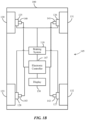
- FIG. 1B illustrates the vehicle 100 with the detection system 105 for detecting wear in the braking system 110 arranged with a disc brake and brake caliper associated with each of the wheels 130, 131, 132, and 133.
- the detection system 105 includes four microphones 140, 141, 142, and 143, one associated with a respective wheel 130, 131, 132, and 133.
- the detection system 105 further includes an electronic controller 147.
- the braking system 110 is similar to the braking system 110 of FIG. 1A , but does not contain the microphone 120.
- the braking system 110 of FIG. 1B includes the at least one brake component 125, and may also include other brake components 126, 127, and 128. As stated above, these brake components 125, 126, 127, and 128 may be brake calipers, brake pads, and the like associated with each respective wheel 130, 131, 132, and 133.
- the electronic controller 147 of FIG. 1B is also similar to the electronic controller 115 of FIG. 1A . However, the electronic controller 147 is communicatively coupled to each of the microphones 140, 141, 142, and 143.
- Each microphone 140, 141, 142, and 143 detects a sound of the respective brake component 125, 126, 127, and 128. In some embodiments, only one of the microphones 140, 141, 142, and 143 detects the sound of the respective brake component 125, 126, 127, 128 to transmit to the electronic controller 147.
- the detected sounds of the brake components 125, 126 127, and 128 are sounds from the brake components 125, 126, 127, and 128 in operation. In other embodiments, more than one of the microphones 140, 141, 142, 143 detect noise from the braking components 125, 126, 127, 128 and transmit the detected sounds to the electronic controller 147.
- the detection system 105 includes a display 150.
- the display 150 is connected to the electronic controller 147 and displays output of the electronic controller 147.
- the display 150 displays a notification generated by the electronic controller 115 to an operator of a vehicle.
- the display 150 is a light-emitting diode (LED) present on a dashboard of the vehicle 100.
- the display 150 is contained within a heads-up display on a dashboard of the vehicle 100 (e.g., a heads-up display for radio, a back-up camera, and other general vehicle use may further contain the display 150).
- FIG. 2 schematically illustrates the electronic controller 115 according to one embodiment.
- the electronic controller 115 comprises an electronic processor 205, a memory 210, and an input/output interface 215.
- the electronic processor 205, the memory 210, and the input/output interface 215 communicate over one or more communication lines or buses, wirelessly, or a combination therefore.
- the electronic controller 115 includes additional components than those illustrated in FIG. 2 and the components included in the electronic controller 115 may be arranged in various configurations.
- the electronic processor 205 may be a microprocessor, an application-specific integrated circuit (ASIC), or another suitable electronic device.
- the electronic processor 205 is configured to retrieve data and instructions from the memory 210 and execute, among other things, software related to the processes and methods described herein.
- the memory 210 includes a non-transitory, computer-readable storage medium.
- the input/output interface 215 may be a wireless transceiver, a modem, and the like.
- the input/output interface 215 is generally configured to receive input from hardware components external from the electronic controller 115 and provide output from the electronic controller 115 to external hardware components.
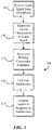
- FIG. 3 is a flowchart illustrating a method 300 for detecting wear in the braking system 110 of the vehicle 100 according to one embodiment.
- the method 300 is performed by the electronic controller 115.
- the electronic controller 115 receives an audio signal from the at least one of the microphones 140, 141, 142, and 143 (block 305).
- the audio signal is generated by the applicable microphone(s) 140, 141, 142, and/or 143 and is based upon a detected sound of a braking component (such as the braking component 125).
- the detected sound of the braking component 125 may be a noise such as a brake pad contacting a wheel, a master cylinder being actuated, and the like.
- the electronic controller 115 receives multiple audio signals from multiple microphones 140, 141, 142, and 143. In those embodiments, the electronic controller 115 is configured to identify which of the microphones 140, 141, 142, and 143 are sending the signals and generates an identifier for each of the audio signals received. In other embodiments, the microphones 140, 141, 142, and 143 generate a formatted audio signal (as described above) which includes an identifier of one of the microphones. Since the microphone is associated with a braking component 125 (such as a brake disc). The identifier provides an indication to the electronic controller 115 regarding which braking component 125 is generating the detected sound.
- a braking component 125 such as a brake disc
- the electronic controller 115 receives the audio signal at block 305 and then, at block 310, determines at least one sound characteristic from the received audio signal. In one embodiment, the electronic controller 115 determines an amplitude of the received audio signal as the at least one sound characteristic. In another embodiment, the at least one sound characteristic determined by the electronic controller 115 is a frequency of the received audio signal. In a further embodiment, the electronic controller 115 determines both an amplitude and frequency of the received audio signal. The determined sound characteristic may further be a delay, a harmonic frequency, and the like.
- the electronic controller 115 determines the condition of the braking component 125 based upon the determined sound characteristic, at block 315.
- the electronic controller 115 compares the sound characteristic to a known sound characteristic. For example, the electronic controller 115 receives an audio signal from a microphone 140 that detects a sound of a brake pad (the braking component 125, in this embodiment). The electronic controller 115 receives the audio signal (block 305) and determines the sound characteristic of the audio signal (at block 310). The electronic controller 115 then compares the amplitude of the audio signal to a known amplitude of the braking component 125 when the braking component 125 is in working or normal condition.
- the amplitude of the detected sound of the braking component 125 may have a higher value (i.e., is louder) than when the braking component 125 is in working or normal condition. If the electronic controller 115 detects such a change in the detected sound, then the electronic controller 115 determines that the braking component 125 has suffered wear.
- the electronic controller 115 determines an amount of wear that the braking component 125 has suffered. For example, if the sound characteristic is an amplitude, the electronic controller 115 may compare it to a known amplitude of sound for the braking component 125 in normal condition. The electronic controller 115 may determine that the amplitude of the received audio signal is greater (for example, two (2) times greater) than the amplitude of an audio signal of the braking component 125 at normal conditions and determine that the braking component 125 has experienced wear (for example, ten (10) percent) from perfect condition.
- the electronic controller 115 does not determine an exact level of wear of the braking component 125, but is instead configured to determine if the wear is above a threshold.
- the electronic controller 115 may be configured to receive the audio signal and determine the sound characteristic from a braking pad (the braking component 125). If the amplitude is determined to be above a certain level (e.g., the amplitude determined is 4 decibels and the threshold is 3 decibels) the electronic controller 115 may indicate (via the display 150, as discussed later) that the braking component 125 needs service or replacement.
- the electronic controller 115 generates a notification involving the braking component 125 condition at block 320. For example, as described above, the electronic controller 115 may determine that the braking component 125 requires servicing or replacing due to the determined sound characteristic. The electronic controller 115 then generates the notification including, in one embodiment, the determined condition of the braking component 125 (e.g., "Requires replacing") and the name of the braking component 125 (e.g., "Left-front wheel brake pad"). The notification may further include a time and date of the notification, an operator of the vehicle, and the like.
- the determined condition of the braking component 125 e.g., "Requires replacing”
- the name of the braking component 125 e.g., "Left-front wheel brake pad”
- the electronic controller 115 then performs at least one action related to the notification at block 325.
- the electronic controller 115 may save the notification into the memory 210 for later use, such as being accessed by a service technician during routine maintenance on the vehicle 100 so the service technician may learn that the braking component 125 needs service or replacement.
- the electronic controller 115 may also send the notification to the display 150 to display for a user.
- the display 150 may be an LED configured to be turned on in response to receiving the notification to alert the user that the braking component 125 has experienced wear or needs replacing.
- the display 150 is a heads-up display in the vehicle 100 and displays the full notification (e.g., "Left-front brake pad needs replaced due to wear") to the user.
- the electronic controller 115 is further configured to modify operation of the vehicle 100 in response to the generated notification. For example, the electronic controller 115 may determine that a braking pad (the braking component 125) needs replacement. In response, the electronic controller 115 generates a signal to the braking system 110 to apply more force to the other brake pads (such as the braking components 126, 127, and 128) so the worn-down braking pad (braking component 125) needs less force and therefore undergoes less wear while the brake pad needs replacing. In other embodiments, the electronic controller 115 is configured to increase pressure in the braking system 110 in order to apply more pressure with the braking component 125 because the braking component 125 has suffered wear.
- the electronic controller 115 may perform one or more of the above-described actions in response to the generation of the notification.
- the electronic controller 115 may further be configured to perform other actions, such as sending the notification via a wireless transceiver to a remote location for alerting a user or monitoring by a user.
- the electronic controller 115 is configured to send the notification, using a wireless transceiver, to a mobile device located in the vehicle, such as a smartphone, cell phone, tablet computer, laptop computer, and the like.
- the mobile device is configured to, in some embodiments, receive the notification and then send the notification to a remote location via a wireless communication method.
- inventions disclosed herein provide, among other things, systems and methods for detecting wear in a braking system in a vehicle.
- the systems and methods generally disclose receiving an audio signal from a microphone; determining at least one sound characteristic of the audio signal; determining a condition of a braking component of the braking system based upon the at least one sound characteristic; generating a notification regarding the condition; and performing at least on selected from the group of sending the notification to a display for output to a user, storing the notification in a memory, and modifying operation of the vehicle.
Landscapes
- Engineering & Computer Science (AREA)
- Mechanical Engineering (AREA)
- General Engineering & Computer Science (AREA)
- Transportation (AREA)
- Physics & Mathematics (AREA)
- Signal Processing (AREA)
- Acoustics & Sound (AREA)
- Health & Medical Sciences (AREA)
- Otolaryngology (AREA)
- General Health & Medical Sciences (AREA)
- Combustion & Propulsion (AREA)
- Chemical & Material Sciences (AREA)
- Braking Arrangements (AREA)
- Valves And Accessory Devices For Braking Systems (AREA)
- Regulating Braking Force (AREA)
Description
- Embodiments relate to systems and methods for detecting wear in a braking system of a vehicle.
- Components of braking systems experience wear during use. For example, brake pads are gradually worn down as they are applied to brake rotors or discs. The application of braking components creates a sound, such as the sound of a brake disc being contacted by a braking pad. As the braking component is repeatedly applied, the braking component experiences wear, and the sound created by the application of the braking component may change.
- Accordingly, embodiments provided herein disclose, among other things, systems and methods for detecting wear in a braking system in a vehicle. The document
FR3030421 A1 - One embodiment provides a system for detecting wear in a braking system of a vehicle. In one example, the system includes a microphone and an electronic controller configured to receive an audio signal from the microphone, determine at least one sound characteristic of the audio signal, determine, based upon the at least one sound characteristic, a condition of a braking component of the braking system, generate a notification regarding the condition, and perform at least one selected from the group of sending the notification to a display for output to a user, storing the notification in a memory, and modifying operation of the vehicle.
- Another embodiment provides a method for detecting wear in a braking system of a vehicle. In one example, the method includes receiving, with an electronic controller, an audio signal from a microphone; determining, with the electronic controller, at least one sound characteristic of the audio signal; determining, with the electronic controller, a condition of a braking component of the braking system based upon the at least one sound characteristic; generating, with the electronic controller, a notification regarding the condition; and performing, with the electronic controller, at least on selected from the group of sending the notification to a display for output to a user, storing the notification in a memory, and modifying operation of the vehicle.
- Other aspects, features, and embodiments will become apparent by consideration of the detailed description and accompanying drawings.
-
-
FIG. 1A illustrates a vehicle with a detection system for detecting wear in a braking system according to one embodiment. -
FIG. 1B illustrates a vehicle with a detection system for detecting wear in a braking system according to an alternative embodiment. -
FIG. 2 schematically illustrates an electronic controller according to one embodiment. -
FIG. 3 is a flowchart illustrating a method for detecting wear in a braking system of a vehicle according to one embodiment. - Before any embodiments are explained in detail, it is to be understood that this disclosure is not intended to be limited in its application to the details of construction and the arrangement of components set forth in the following description or illustrated in the following drawings. Embodiments are capable of other configurations and of being practiced or of being carried out in various ways.
- A plurality of hardware and software based devices, as well as a plurality of different structural components may be used to implement various embodiments. In addition, embodiments may include hardware, software, and electronic components or modules that, for purposes of discussion, may be illustrated and described as if the majority of the components were implemented solely in hardware. However, one of ordinary skill in the art, and based on a reading of this detailed description, would recognize that, in at least one embodiment, the electronic based aspects of the invention may be implemented in software (for example, stored on non-transitory computer-readable medium) executable by one or more processors. For example, "control units" and "controllers" described in the specification can include one or more electronic processors, one or more memory modules including non-transitory computer-readable medium, one or more input/output interfaces, one or more application specific integrated circuits (ASICs), one or more programmable logic controllers (PLCs), and various connections (for example, a system bus) connecting the various components.
-
Fig. 1A illustrates avehicle 100 equipped with adetection system 105 for detecting a wear in abraking system 110 according to a first embodiment. Thevehicle 100 also includes anelectronic controller 115. - In the example shown, the
braking system 110 includes amicrophone 120 and at least onebraking component 125. Thebraking system 110 is configured to apply thebraking component 125 to slow a speed of thevehicle 100. In some embodiments, thebraking system 110 receives manual input from an operator of thevehicle 100, such as the operator of thevehicle 100 depressing a brake pedal, in order to apply thebraking component 125. In some embodiments, thebraking system 110 also includes a braking system electronic controller configured to receive signals to actuate thebraking component 125 and further configured to control the actuation of thebraking component 125. In other embodiments, thebraking system 110 is controlled by theelectronic controller 115 or a different electronic controller of thevehicle 100. - The
electronic controller 115 is communicatively coupled to thebraking system 110 according to one embodiment. In other embodiments, theelectronic controller 115 is communicatively coupled to themicrophone 120 of thebraking system 110. Theelectronic controller 115 may be communicatively coupled to each of the noted components of thedetection system 105 via a dedicated wire, a shared communication link such as a vehicle communication bus (for example, a controller area network (CAN) bus) or a wireless vehicle network. - The
microphone 120 is configured to detect a sound of thebraking component 125. The detected sound of thebraking component 125 is a sound of the at least onebraking component 125 in operation. In some embodiments, themicrophone 120 is a micro-electrical mechanical system (MEMS) microphone. Themicrophone 120, in some embodiments, is further configured to generate a signal containing data regarding the detected sound of thebraking component 125 and transmit the signal to theelectronic controller 115 either directly or through an electronic controller of thebraking system 110. In some embodiments, themicrophone 120 is comprised of an array of microphones in order to more accurately detect the sound of the at least onebraking component 125. For example, each microphone in the array ofmicrophones 120 can be configured to detect a specific frequency range, increasing the accuracy with which the array ofmicrophones 120 can detect specific sounds. - The
braking component 125 may be a master cylinder, a piston, a brake caliper, and the like. Thebraking component 125 is actuated to help slow the speed of thevehicle 100. In one example, thebraking component 125 is a master cylinder. A master cylinder in a braking system (such as the braking system 110) contains a piston designed to apply pressure to hydraulic fluid to pressurize fluid that ultimately drives brake calipers and/or brake pads, which create contact with a brake rotor or disc of at least one wheel (for example, one of thewheels vehicle 100 in order to slow thewheels vehicle 100. -
FIG. 1B illustrates thevehicle 100 with thedetection system 105 for detecting wear in thebraking system 110 arranged with a disc brake and brake caliper associated with each of thewheels FIG. 1B , thedetection system 105 includes fourmicrophones respective wheel detection system 105 further includes anelectronic controller 147. - In the embodiment shown in
FIG. 1B , thebraking system 110 is similar to thebraking system 110 ofFIG. 1A , but does not contain themicrophone 120. Thebraking system 110 ofFIG. 1B includes the at least onebrake component 125, and may also includeother brake components brake components respective wheel - The
electronic controller 147 ofFIG. 1B is also similar to theelectronic controller 115 ofFIG. 1A . However, theelectronic controller 147 is communicatively coupled to each of themicrophones - Each
microphone respective brake component microphones respective brake component electronic controller 147. The detected sounds of thebrake components brake components microphones braking components electronic controller 147. - In the example illustrated in
Fig. 1B , thedetection system 105 includes adisplay 150. Thedisplay 150 is connected to theelectronic controller 147 and displays output of theelectronic controller 147. In one example, thedisplay 150 displays a notification generated by theelectronic controller 115 to an operator of a vehicle. In one embodiment, thedisplay 150 is a light-emitting diode (LED) present on a dashboard of thevehicle 100. In a further embodiment, thedisplay 150 is contained within a heads-up display on a dashboard of the vehicle 100 (e.g., a heads-up display for radio, a back-up camera, and other general vehicle use may further contain the display 150). -
FIG. 2 schematically illustrates theelectronic controller 115 according to one embodiment. Theelectronic controller 115 comprises anelectronic processor 205, amemory 210, and an input/output interface 215. Theelectronic processor 205, thememory 210, and the input/output interface 215 communicate over one or more communication lines or buses, wirelessly, or a combination therefore. In some embodiments, theelectronic controller 115 includes additional components than those illustrated inFIG. 2 and the components included in theelectronic controller 115 may be arranged in various configurations. - The
electronic processor 205 may be a microprocessor, an application-specific integrated circuit (ASIC), or another suitable electronic device. In one example, theelectronic processor 205 is configured to retrieve data and instructions from thememory 210 and execute, among other things, software related to the processes and methods described herein. Thememory 210 includes a non-transitory, computer-readable storage medium. - The input/
output interface 215 may be a wireless transceiver, a modem, and the like. The input/output interface 215 is generally configured to receive input from hardware components external from theelectronic controller 115 and provide output from theelectronic controller 115 to external hardware components. -
FIG. 3 is a flowchart illustrating amethod 300 for detecting wear in thebraking system 110 of thevehicle 100 according to one embodiment. In the example provided, themethod 300 is performed by theelectronic controller 115. - The
electronic controller 115 receives an audio signal from the at least one of themicrophones braking component 125 may be a noise such as a brake pad contacting a wheel, a master cylinder being actuated, and the like. - In some embodiments, the
electronic controller 115 receives multiple audio signals frommultiple microphones electronic controller 115 is configured to identify which of themicrophones microphones electronic controller 115 regarding whichbraking component 125 is generating the detected sound. - The
electronic controller 115 receives the audio signal atblock 305 and then, atblock 310, determines at least one sound characteristic from the received audio signal. In one embodiment, theelectronic controller 115 determines an amplitude of the received audio signal as the at least one sound characteristic. In another embodiment, the at least one sound characteristic determined by theelectronic controller 115 is a frequency of the received audio signal. In a further embodiment, theelectronic controller 115 determines both an amplitude and frequency of the received audio signal. The determined sound characteristic may further be a delay, a harmonic frequency, and the like. - The
electronic controller 115 determines the condition of thebraking component 125 based upon the determined sound characteristic, atblock 315. Theelectronic controller 115, in one embodiment, compares the sound characteristic to a known sound characteristic. For example, theelectronic controller 115 receives an audio signal from amicrophone 140 that detects a sound of a brake pad (thebraking component 125, in this embodiment). Theelectronic controller 115 receives the audio signal (block 305) and determines the sound characteristic of the audio signal (at block 310). Theelectronic controller 115 then compares the amplitude of the audio signal to a known amplitude of thebraking component 125 when thebraking component 125 is in working or normal condition. If thebraking component 125 has suffered wear, the amplitude of the detected sound of thebraking component 125 may have a higher value (i.e., is louder) than when thebraking component 125 is in working or normal condition. If theelectronic controller 115 detects such a change in the detected sound, then theelectronic controller 115 determines that thebraking component 125 has suffered wear. - In some embodiments, the
electronic controller 115 determines an amount of wear that thebraking component 125 has suffered. For example, if the sound characteristic is an amplitude, theelectronic controller 115 may compare it to a known amplitude of sound for thebraking component 125 in normal condition. Theelectronic controller 115 may determine that the amplitude of the received audio signal is greater (for example, two (2) times greater) than the amplitude of an audio signal of thebraking component 125 at normal conditions and determine that thebraking component 125 has experienced wear (for example, ten (10) percent) from perfect condition. - In other embodiments, the
electronic controller 115 does not determine an exact level of wear of thebraking component 125, but is instead configured to determine if the wear is above a threshold. For example, theelectronic controller 115 may be configured to receive the audio signal and determine the sound characteristic from a braking pad (the braking component 125). If the amplitude is determined to be above a certain level (e.g., the amplitude determined is 4 decibels and the threshold is 3 decibels) theelectronic controller 115 may indicate (via thedisplay 150, as discussed later) that thebraking component 125 needs service or replacement. - The
electronic controller 115 generates a notification involving thebraking component 125 condition atblock 320. For example, as described above, theelectronic controller 115 may determine that thebraking component 125 requires servicing or replacing due to the determined sound characteristic. Theelectronic controller 115 then generates the notification including, in one embodiment, the determined condition of the braking component 125 (e.g., "Requires replacing") and the name of the braking component 125 (e.g., "Left-front wheel brake pad"). The notification may further include a time and date of the notification, an operator of the vehicle, and the like. - The
electronic controller 115 then performs at least one action related to the notification atblock 325. Theelectronic controller 115 may save the notification into thememory 210 for later use, such as being accessed by a service technician during routine maintenance on thevehicle 100 so the service technician may learn that thebraking component 125 needs service or replacement. - The
electronic controller 115 may also send the notification to thedisplay 150 to display for a user. As discussed above, thedisplay 150 may be an LED configured to be turned on in response to receiving the notification to alert the user that thebraking component 125 has experienced wear or needs replacing. In another embodiment, thedisplay 150 is a heads-up display in thevehicle 100 and displays the full notification (e.g., "Left-front brake pad needs replaced due to wear") to the user. - The
electronic controller 115 is further configured to modify operation of thevehicle 100 in response to the generated notification. For example, theelectronic controller 115 may determine that a braking pad (the braking component 125) needs replacement. In response, theelectronic controller 115 generates a signal to thebraking system 110 to apply more force to the other brake pads (such as thebraking components electronic controller 115 is configured to increase pressure in thebraking system 110 in order to apply more pressure with thebraking component 125 because thebraking component 125 has suffered wear. - The
electronic controller 115 may perform one or more of the above-described actions in response to the generation of the notification. Theelectronic controller 115 may further be configured to perform other actions, such as sending the notification via a wireless transceiver to a remote location for alerting a user or monitoring by a user. In some embodiments, theelectronic controller 115 is configured to send the notification, using a wireless transceiver, to a mobile device located in the vehicle, such as a smartphone, cell phone, tablet computer, laptop computer, and the like. The mobile device is configured to, in some embodiments, receive the notification and then send the notification to a remote location via a wireless communication method. - Therefore, embodiments disclosed herein provide, among other things, systems and methods for detecting wear in a braking system in a vehicle. The systems and methods generally disclose receiving an audio signal from a microphone; determining at least one sound characteristic of the audio signal; determining a condition of a braking component of the braking system based upon the at least one sound characteristic; generating a notification regarding the condition; and performing at least on selected from the group of sending the notification to a display for output to a user, storing the notification in a memory, and modifying operation of the vehicle.
- Various features, advantages, and embodiments are set forth in the following claims.
Claims (18)
- A system for monitoring brake wear in a braking system of a vehicle, the system comprising:a microphone; andan electronic controller configured toreceive an audio signal from the microphone,determine at least one sound characteristic of the audio signal,determine, based upon the at least one sound characteristic, a condition of a braking component of the braking system,generate a notification regarding the condition, andperform at least one selected from the group of sending the notification to a display for output to a user, storing the notification in a memory, and modifying operation of the vehicle, characterized in thatthe electronic controller (115) is further configured to modify an operation of the vehicle (100) in response to the generated notification wherein the electronic controller (115) determines that a braking pad needs replacement and in response, the electronic controller (115) generates a signal to the braking system (110) to apply more force to other brake pads.
- The system of claim 1, wherein the sound characteristic is an amplitude.
- The system of claim 1, wherein the sound characteristic is a frequency.
- The system of claim 1, the system further comprising a wireless communication device.
- The system of claim 4, wherein the electronic controller is further configured to generate a signal containing notification.
- The system of claim 5, wherein the electronic controller is further configured to send the signal to a remote location via the wireless communication device.
- The system of claim 5, wherein the electronic controller is further configured to send the signal to a mobile device which is configured to send the signal to a remote location.
- The system of claim 1, wherein the electronic controller is configured to determine the condition of the braking component by comparing the at least one sound characteristic to a known sound characteristic of the braking component.
- The system of claim 1, wherein the microphone is configured to receive audio data from the braking component of the braking system.
- The system of claim 8, wherein the audio signal includes the audio data from the braking component of the braking system.
- A method for monitoring brake wear in a braking system of a vehicle, the method comprising:receiving, with an electronic controller, an audio signal from a microphone;determining, with the electronic controller, at least one sound characteristic of the audio signal;determining, with the electronic controller, a condition of a braking component of the braking system based upon the at least one sound characteristic;generating, with the electronic controller, a notification regarding the condition; characterized by the method steps that the electronic controller (115) modifies an operation of the vehicle (100) in response to the generated notification wherein the electronic controller (115) determines that a braking pad needs replacement and in response, the electronic controller (115) generates a signal to the braking system (110) to apply more force to other brake pads. and performing with the electronic controller, at least one selected from the group of sending the notification to a display for output to a user, storing the notification in a memory, and modifying operation of the vehicle.
- The method of claim 11, wherein the sound characteristic is an amplitude.
- The method of claim 11, wherein the sound characteristic is a frequency.
- The method of claim 11, the method further comprising sending, via the electronic controller, the generated notification via a wireless communication device to a remote location.
- The method of claim 11, the method further comprising sending, via the electronic controller, the generated notification via a wireless communication device to a mobile device configured to send the generated notification to a remote location.
- The method of claim 11, the method further comprising determining the condition of the braking component by comparing the at least one sound characteristic to a known sound characteristic of the brake component.
- The method of claim 11, the method further including receiving audio data from the braking component with the microphone.
- The method of claim 17, wherein the audio signal includes the audio data from the braking component of the braking system.
Applications Claiming Priority (2)
| Application Number | Priority Date | Filing Date | Title |
|---|---|---|---|
| US15/717,390 US10539200B2 (en) | 2017-09-27 | 2017-09-27 | Sound-based brake wear detection for vehicle braking systems |
| PCT/EP2018/071620 WO2019063179A1 (en) | 2017-09-27 | 2018-08-09 | Sound-based brake wear detection for vehicle braking systems |
Publications (2)
| Publication Number | Publication Date |
|---|---|
| EP3687873A1 EP3687873A1 (en) | 2020-08-05 |
| EP3687873B1 true EP3687873B1 (en) | 2023-03-08 |
Family
ID=63244570
Family Applications (1)
| Application Number | Title | Priority Date | Filing Date |
|---|---|---|---|
| EP18755758.2A Active EP3687873B1 (en) | 2017-09-27 | 2018-08-09 | Sound-based brake wear detection for vehicle braking systems |
Country Status (6)
| Country | Link |
|---|---|
| US (1) | US10539200B2 (en) |
| EP (1) | EP3687873B1 (en) |
| JP (1) | JP6926328B2 (en) |
| KR (1) | KR102586267B1 (en) |
| CN (1) | CN111108030B (en) |
| WO (1) | WO2019063179A1 (en) |
Families Citing this family (10)
| Publication number | Priority date | Publication date | Assignee | Title |
|---|---|---|---|---|
| US10486675B2 (en) * | 2017-11-11 | 2019-11-26 | Brian Hearing | Vehicle brake monitoring through ultrasonic emissions |
| DE102019215666B4 (en) * | 2019-10-11 | 2022-09-22 | Zf Friedrichshafen Ag | Process unit for brake noise detection of brake noises generated by a host vehicle, host vehicle and method |
| DE102020209195A1 (en) | 2020-07-22 | 2022-01-27 | Robert Bosch Gesellschaft mit beschränkter Haftung | Sensor system for monitoring a braking system |
| EP4211609A1 (en) * | 2020-09-10 | 2023-07-19 | Volvo Truck Corporation | Commercial vehicles rotor cracking prediction using recurrent neural network |
| DE102020212789A1 (en) | 2020-10-09 | 2022-04-14 | Continental Teves Ag & Co. Ohg | Electromechanical motor vehicle wheel brake with locally improved monitoring |
| IT202100025136A1 (en) * | 2021-09-30 | 2023-03-30 | Brembo Spa | METHOD FOR CONTROLLING THE DISTRIBUTION OF BRAKING FORCES IN A VEHICLE BRAKING SYSTEM TO REDUCE OR ELIMINATE NOISE AND/OR VIBRATIONS GENERATED IN THE SYSTEM |
| US11841058B2 (en) * | 2022-01-14 | 2023-12-12 | Ford Global Technologies, Llc | Methods and apparatus to determine brake pad wear |
| IT202200019035A1 (en) * | 2022-09-16 | 2024-03-16 | Fca Italy Spa | “PROCEDURE TO REDUCE OR ELIMINATE THE NOISE GENERATED BY THE BRAKES OF A MOTOR VEHICLE” |
| US12209628B2 (en) * | 2022-12-28 | 2025-01-28 | Apollo Autonomous Driving USA LLC | Brake pad wear detection and warning for autonomous driving vehicles |
| WO2025073033A1 (en) * | 2023-10-05 | 2025-04-10 | Instituto Hercílio Randon | Method and device for monitoring the state of health of a brake system |
Family Cites Families (36)
| Publication number | Priority date | Publication date | Assignee | Title |
|---|---|---|---|---|
| JPS54134265A (en) | 1978-04-10 | 1979-10-18 | Nissan Motor Co Ltd | Antiskid device |
| US4266633A (en) * | 1979-03-08 | 1981-05-12 | Safety Research & Engineering Corporation | Brake wear warning system |
| GB8905022D0 (en) * | 1989-03-04 | 1989-04-19 | Lucas Ind Plc | Electronic braking system |
| FR2681922B1 (en) * | 1991-09-30 | 1993-11-26 | Bendix Europe Services Technique | FRICTION MEMBER PROVIDED WITH A WEAR INDICATOR DEVICE AND DISC BRAKE EQUIPPED WITH SUCH A MEMBER. |
| JPH0761340A (en) | 1993-08-25 | 1995-03-07 | Nippon Denshi Kogyo Kk | Control point detecting method in abs device |
| US5586028A (en) | 1993-12-07 | 1996-12-17 | Honda Giken Kogyo Kabushiki Kaisha | Road surface condition-detecting system and anti-lock brake system employing same |
| DE4438017C2 (en) * | 1994-10-25 | 1996-10-31 | Bosch Gmbh Robert | Method and device for the electrical control or regulation of the brake system of a vehicle |
| JP2000177552A (en) | 1998-12-15 | 2000-06-27 | Akebono Brake Ind Co Ltd | Brake noise preventing device |
| JP4267173B2 (en) | 2000-05-01 | 2009-05-27 | トヨタ自動車株式会社 | Abnormality diagnosis system |
| EP1970274B1 (en) * | 2000-08-04 | 2014-01-08 | Meggitt Aerospace Limited | Brake condition monitoring |
| JP2002274358A (en) | 2001-03-23 | 2002-09-25 | Unisia Jecs Corp | Anti-skid control device |
| US20040186648A1 (en) | 2002-09-26 | 2004-09-23 | Yuhong Zheng | Boundary auto-calibration scheme for proportional poppet valve pressure control |
| DE10335616B4 (en) | 2003-08-04 | 2006-06-14 | Lucas Automotive Gmbh | Low-noise vehicle brake system |
| JP4363143B2 (en) | 2003-09-24 | 2009-11-11 | 株式会社アドヴィックス | Traction control device |
| WO2006030786A1 (en) | 2004-09-13 | 2006-03-23 | Nsk Ltd. | Abnormality diagnosis device and abnormality diagnosis method |
| WO2008109237A2 (en) | 2007-02-13 | 2008-09-12 | Washington State University Research Foundation | Macrophage cell-lines for propagation of porcine reproductive and respiratory syndrome virus |
| CN101029855A (en) * | 2007-04-05 | 2007-09-05 | 童军 | Method and apparatus for instantaneouslly inspecting motor vehicle fault |
| JP2009168210A (en) * | 2008-01-18 | 2009-07-30 | Toyota Motor Corp | Brake pad wear detector, lining wear detector |
| US20110012720A1 (en) * | 2009-07-15 | 2011-01-20 | Hirschfeld Robert A | Integration of Vehicle On-Board Diagnostics and Smart Phone Sensors |
| DE102010003076A1 (en) | 2009-08-05 | 2011-08-18 | Continental Automotive GmbH, 30165 | Method for controlling a wheel brake slip and wheel brake slip control system for a vehicle with an electric drive |
| US8509982B2 (en) | 2010-10-05 | 2013-08-13 | Google Inc. | Zone driving |
| WO2013011490A1 (en) | 2011-07-21 | 2013-01-24 | Compound Technology (Proprietary) Limited | Acoustic wear sensor |
| US9315178B1 (en) | 2012-04-13 | 2016-04-19 | Google Inc. | Model checking for autonomous vehicles |
| TWI486916B (en) | 2012-09-05 | 2015-06-01 | Kepro Dev Inc | Tire pressure detection warning system |
| US20140136643A1 (en) | 2012-11-13 | 2014-05-15 | Motorola Mobility Llc | Dynamic Buffer Management for a Multimedia Content Delivery System |
| US10222462B2 (en) | 2013-02-27 | 2019-03-05 | Waymo Llc | Adaptive algorithms for interrogating the viewable scene of an automotive radar |
| US8886412B2 (en) | 2013-03-14 | 2014-11-11 | GM Global Technology Operations LLC | Steering system for an autonomously driven vehicle and methods of steering the same |
| US20150081159A1 (en) * | 2013-09-17 | 2015-03-19 | Hyundai Motor Company | Apparatus and method of sensing and controlling wear of brake lining |
| DE102013222228A1 (en) * | 2013-10-31 | 2015-04-30 | Robert Bosch Gmbh | Method and device for determining the thickness of a brake disk |
| US9720410B2 (en) | 2014-03-03 | 2017-08-01 | Waymo Llc | Remote assistance for autonomous vehicles in predetermined situations |
| FR3030421B1 (en) | 2014-12-23 | 2018-04-06 | Renault S.A.S. | AUTOMATIC DETECTION OF A LEVEL OF WEAR OF A BRAKE PAD |
| DE102015105862A1 (en) * | 2015-04-17 | 2016-10-20 | Knorr-Bremse Systeme für Nutzfahrzeuge GmbH | Method for increasing the operational reliability of thermally loaded functional parts of a disc brake |
| DE102015009443A1 (en) | 2015-07-21 | 2016-03-24 | Daimler Ag | Method for reducing the brake noise occurring during braking of a motor vehicle |
| TWI577981B (en) | 2015-08-27 | 2017-04-11 | 久朝企業有限公司 | Instant detection system of vehicle |
| JP6464500B2 (en) | 2016-03-11 | 2019-02-06 | パナソニックIpマネジメント株式会社 | Automatic vehicle allocation system and server device |
| US10239531B2 (en) | 2017-01-10 | 2019-03-26 | GM Global Technology Operations LLC | Fault-tolerant automotive braking system |
-
2017
- 2017-09-27 US US15/717,390 patent/US10539200B2/en active Active
-
2018
- 2018-08-09 EP EP18755758.2A patent/EP3687873B1/en active Active
- 2018-08-09 JP JP2020517524A patent/JP6926328B2/en not_active Expired - Fee Related
- 2018-08-09 KR KR1020207008739A patent/KR102586267B1/en active Active
- 2018-08-09 CN CN201880062776.2A patent/CN111108030B/en active Active
- 2018-08-09 WO PCT/EP2018/071620 patent/WO2019063179A1/en not_active Ceased
Also Published As
| Publication number | Publication date |
|---|---|
| KR102586267B1 (en) | 2023-10-11 |
| EP3687873A1 (en) | 2020-08-05 |
| US10539200B2 (en) | 2020-01-21 |
| JP6926328B2 (en) | 2021-08-25 |
| KR20200055724A (en) | 2020-05-21 |
| US20190093722A1 (en) | 2019-03-28 |
| WO2019063179A1 (en) | 2019-04-04 |
| CN111108030A (en) | 2020-05-05 |
| JP2020535360A (en) | 2020-12-03 |
| CN111108030B (en) | 2022-08-23 |
Similar Documents
| Publication | Publication Date | Title |
|---|---|---|
| EP3687873B1 (en) | Sound-based brake wear detection for vehicle braking systems | |
| US20210388878A1 (en) | Hot runner detection and response systems, devices, and methods | |
| CN111511617B (en) | Real-time pressure-volume curve generation for hydraulic systems | |
| CN109606343B (en) | Monitoring of vehicle brake pads | |
| US20190234475A1 (en) | Methods, systems, and media for non-contact brake pad wear determination | |
| US20170217419A1 (en) | Vehicle brake system health diagnostic, prognostic, and reporting apparatus | |
| JP2017128325A5 (en) | ||
| KR20150100304A (en) | System for Abrasion Warning of Brake Friction Pad Using ESC System | |
| CN106458199B (en) | Apparatus and method for operating a vehicle | |
| US10486713B2 (en) | Dynamic stuck switch monitoring | |
| JP6928681B2 (en) | How to suppress brake noise, central server, vehicle control module and storage medium | |
| CN111328312B (en) | System and method for performing diagnostics on a vehicle hydraulic system in a stopped state | |
| CN115583233A (en) | A detection method, device and electronic equipment for brake fluid leakage | |
| CN111278693B (en) | System and method for stabilizing a vehicle | |
| US9205789B2 (en) | Method for monitoring vehicle systems during maintenance work on the vehicle | |
| CN110901624B (en) | Friction braking fault detection method and device, readable storage medium and controller | |
| CN107810130A (en) | Rail vehicle braking system and method of operating the rail vehicle braking system | |
| CN115230671A (en) | Monitoring method, monitoring system and braking system for thickness of brake friction lining | |
| JP7238696B2 (en) | Wear detector and brake system | |
| WO2009024718A3 (en) | System and method for diagnosing the operation of an automobile | |
| CN101999049A (en) | Method of identifying positions of brake monitors | |
| JP2024046484A (en) | Tire condition monitoring system | |
| JP2025535347A (en) | Brake system control device, system for controlling a brake system, and method for controlling a brake system | |
| CN110785332A (en) | Acoustic system and method for traction/brake control of trains | |
| JP2017127069A (en) | Train data transmission method |
Legal Events
| Date | Code | Title | Description |
|---|---|---|---|
| STAA | Information on the status of an ep patent application or granted ep patent |
Free format text: STATUS: UNKNOWN |
|
| STAA | Information on the status of an ep patent application or granted ep patent |
Free format text: STATUS: THE INTERNATIONAL PUBLICATION HAS BEEN MADE |
|
| PUAI | Public reference made under article 153(3) epc to a published international application that has entered the european phase |
Free format text: ORIGINAL CODE: 0009012 |
|
| STAA | Information on the status of an ep patent application or granted ep patent |
Free format text: STATUS: REQUEST FOR EXAMINATION WAS MADE |
|
| 17P | Request for examination filed |
Effective date: 20200428 |
|
| AK | Designated contracting states |
Kind code of ref document: A1 Designated state(s): AL AT BE BG CH CY CZ DE DK EE ES FI FR GB GR HR HU IE IS IT LI LT LU LV MC MK MT NL NO PL PT RO RS SE SI SK SM TR |
|
| AX | Request for extension of the european patent |
Extension state: BA ME |
|
| DAV | Request for validation of the european patent (deleted) | ||
| DAX | Request for extension of the european patent (deleted) | ||
| GRAP | Despatch of communication of intention to grant a patent |
Free format text: ORIGINAL CODE: EPIDOSNIGR1 |
|
| STAA | Information on the status of an ep patent application or granted ep patent |
Free format text: STATUS: GRANT OF PATENT IS INTENDED |
|
| INTG | Intention to grant announced |
Effective date: 20221111 |
|
| GRAS | Grant fee paid |
Free format text: ORIGINAL CODE: EPIDOSNIGR3 |
|
| GRAA | (expected) grant |
Free format text: ORIGINAL CODE: 0009210 |
|
| STAA | Information on the status of an ep patent application or granted ep patent |
Free format text: STATUS: THE PATENT HAS BEEN GRANTED |
|
| AK | Designated contracting states |
Kind code of ref document: B1 Designated state(s): AL AT BE BG CH CY CZ DE DK EE ES FI FR GB GR HR HU IE IS IT LI LT LU LV MC MK MT NL NO PL PT RO RS SE SI SK SM TR |
|
| REG | Reference to a national code |
Ref country code: CH Ref legal event code: EP Ref country code: AT Ref legal event code: REF Ref document number: 1552401 Country of ref document: AT Kind code of ref document: T Effective date: 20230315 |
|
| REG | Reference to a national code |
Ref country code: IE Ref legal event code: FG4D |
|
| REG | Reference to a national code |
Ref country code: DE Ref legal event code: R096 Ref document number: 602018046986 Country of ref document: DE |
|
| REG | Reference to a national code |
Ref country code: LT Ref legal event code: MG9D |
|
| REG | Reference to a national code |
Ref country code: NL Ref legal event code: MP Effective date: 20230308 |
|
| PG25 | Lapsed in a contracting state [announced via postgrant information from national office to epo] |
Ref country code: RS Free format text: LAPSE BECAUSE OF FAILURE TO SUBMIT A TRANSLATION OF THE DESCRIPTION OR TO PAY THE FEE WITHIN THE PRESCRIBED TIME-LIMIT Effective date: 20230308 Ref country code: NO Free format text: LAPSE BECAUSE OF FAILURE TO SUBMIT A TRANSLATION OF THE DESCRIPTION OR TO PAY THE FEE WITHIN THE PRESCRIBED TIME-LIMIT Effective date: 20230608 Ref country code: LV Free format text: LAPSE BECAUSE OF FAILURE TO SUBMIT A TRANSLATION OF THE DESCRIPTION OR TO PAY THE FEE WITHIN THE PRESCRIBED TIME-LIMIT Effective date: 20230308 Ref country code: LT Free format text: LAPSE BECAUSE OF FAILURE TO SUBMIT A TRANSLATION OF THE DESCRIPTION OR TO PAY THE FEE WITHIN THE PRESCRIBED TIME-LIMIT Effective date: 20230308 Ref country code: HR Free format text: LAPSE BECAUSE OF FAILURE TO SUBMIT A TRANSLATION OF THE DESCRIPTION OR TO PAY THE FEE WITHIN THE PRESCRIBED TIME-LIMIT Effective date: 20230308 Ref country code: ES Free format text: LAPSE BECAUSE OF FAILURE TO SUBMIT A TRANSLATION OF THE DESCRIPTION OR TO PAY THE FEE WITHIN THE PRESCRIBED TIME-LIMIT Effective date: 20230308 |
|
| REG | Reference to a national code |
Ref country code: AT Ref legal event code: MK05 Ref document number: 1552401 Country of ref document: AT Kind code of ref document: T Effective date: 20230308 |
|
| PG25 | Lapsed in a contracting state [announced via postgrant information from national office to epo] |
Ref country code: SE Free format text: LAPSE BECAUSE OF FAILURE TO SUBMIT A TRANSLATION OF THE DESCRIPTION OR TO PAY THE FEE WITHIN THE PRESCRIBED TIME-LIMIT Effective date: 20230308 Ref country code: NL Free format text: LAPSE BECAUSE OF FAILURE TO SUBMIT A TRANSLATION OF THE DESCRIPTION OR TO PAY THE FEE WITHIN THE PRESCRIBED TIME-LIMIT Effective date: 20230308 Ref country code: GR Free format text: LAPSE BECAUSE OF FAILURE TO SUBMIT A TRANSLATION OF THE DESCRIPTION OR TO PAY THE FEE WITHIN THE PRESCRIBED TIME-LIMIT Effective date: 20230609 Ref country code: FI Free format text: LAPSE BECAUSE OF FAILURE TO SUBMIT A TRANSLATION OF THE DESCRIPTION OR TO PAY THE FEE WITHIN THE PRESCRIBED TIME-LIMIT Effective date: 20230308 |
|
| PG25 | Lapsed in a contracting state [announced via postgrant information from national office to epo] |
Ref country code: SM Free format text: LAPSE BECAUSE OF FAILURE TO SUBMIT A TRANSLATION OF THE DESCRIPTION OR TO PAY THE FEE WITHIN THE PRESCRIBED TIME-LIMIT Effective date: 20230308 Ref country code: RO Free format text: LAPSE BECAUSE OF FAILURE TO SUBMIT A TRANSLATION OF THE DESCRIPTION OR TO PAY THE FEE WITHIN THE PRESCRIBED TIME-LIMIT Effective date: 20230308 Ref country code: PT Free format text: LAPSE BECAUSE OF FAILURE TO SUBMIT A TRANSLATION OF THE DESCRIPTION OR TO PAY THE FEE WITHIN THE PRESCRIBED TIME-LIMIT Effective date: 20230710 Ref country code: EE Free format text: LAPSE BECAUSE OF FAILURE TO SUBMIT A TRANSLATION OF THE DESCRIPTION OR TO PAY THE FEE WITHIN THE PRESCRIBED TIME-LIMIT Effective date: 20230308 Ref country code: CZ Free format text: LAPSE BECAUSE OF FAILURE TO SUBMIT A TRANSLATION OF THE DESCRIPTION OR TO PAY THE FEE WITHIN THE PRESCRIBED TIME-LIMIT Effective date: 20230308 Ref country code: AT Free format text: LAPSE BECAUSE OF FAILURE TO SUBMIT A TRANSLATION OF THE DESCRIPTION OR TO PAY THE FEE WITHIN THE PRESCRIBED TIME-LIMIT Effective date: 20230308 |
|
| PG25 | Lapsed in a contracting state [announced via postgrant information from national office to epo] |
Ref country code: SK Free format text: LAPSE BECAUSE OF FAILURE TO SUBMIT A TRANSLATION OF THE DESCRIPTION OR TO PAY THE FEE WITHIN THE PRESCRIBED TIME-LIMIT Effective date: 20230308 Ref country code: PL Free format text: LAPSE BECAUSE OF FAILURE TO SUBMIT A TRANSLATION OF THE DESCRIPTION OR TO PAY THE FEE WITHIN THE PRESCRIBED TIME-LIMIT Effective date: 20230308 Ref country code: IS Free format text: LAPSE BECAUSE OF FAILURE TO SUBMIT A TRANSLATION OF THE DESCRIPTION OR TO PAY THE FEE WITHIN THE PRESCRIBED TIME-LIMIT Effective date: 20230708 |
|
| REG | Reference to a national code |
Ref country code: DE Ref legal event code: R097 Ref document number: 602018046986 Country of ref document: DE |
|
| PLBE | No opposition filed within time limit |
Free format text: ORIGINAL CODE: 0009261 |
|
| STAA | Information on the status of an ep patent application or granted ep patent |
Free format text: STATUS: NO OPPOSITION FILED WITHIN TIME LIMIT |
|
| PG25 | Lapsed in a contracting state [announced via postgrant information from national office to epo] |
Ref country code: SI Free format text: LAPSE BECAUSE OF FAILURE TO SUBMIT A TRANSLATION OF THE DESCRIPTION OR TO PAY THE FEE WITHIN THE PRESCRIBED TIME-LIMIT Effective date: 20230308 Ref country code: DK Free format text: LAPSE BECAUSE OF FAILURE TO SUBMIT A TRANSLATION OF THE DESCRIPTION OR TO PAY THE FEE WITHIN THE PRESCRIBED TIME-LIMIT Effective date: 20230308 |
|
| 26N | No opposition filed |
Effective date: 20231211 |
|
| PG25 | Lapsed in a contracting state [announced via postgrant information from national office to epo] |
Ref country code: MC Free format text: LAPSE BECAUSE OF FAILURE TO SUBMIT A TRANSLATION OF THE DESCRIPTION OR TO PAY THE FEE WITHIN THE PRESCRIBED TIME-LIMIT Effective date: 20230308 |
|
| REG | Reference to a national code |
Ref country code: CH Ref legal event code: PL |
|
| PG25 | Lapsed in a contracting state [announced via postgrant information from national office to epo] |
Ref country code: MC Free format text: LAPSE BECAUSE OF FAILURE TO SUBMIT A TRANSLATION OF THE DESCRIPTION OR TO PAY THE FEE WITHIN THE PRESCRIBED TIME-LIMIT Effective date: 20230308 |
|
| PG25 | Lapsed in a contracting state [announced via postgrant information from national office to epo] |
Ref country code: LU Free format text: LAPSE BECAUSE OF NON-PAYMENT OF DUE FEES Effective date: 20230809 |
|
| GBPC | Gb: european patent ceased through non-payment of renewal fee |
Effective date: 20230809 |
|
| PG25 | Lapsed in a contracting state [announced via postgrant information from national office to epo] |
Ref country code: LU Free format text: LAPSE BECAUSE OF NON-PAYMENT OF DUE FEES Effective date: 20230809 Ref country code: CH Free format text: LAPSE BECAUSE OF NON-PAYMENT OF DUE FEES Effective date: 20230831 |
|
| REG | Reference to a national code |
Ref country code: BE Ref legal event code: MM Effective date: 20230831 |
|
| REG | Reference to a national code |
Ref country code: IE Ref legal event code: MM4A |
|
| PG25 | Lapsed in a contracting state [announced via postgrant information from national office to epo] |
Ref country code: IT Free format text: LAPSE BECAUSE OF FAILURE TO SUBMIT A TRANSLATION OF THE DESCRIPTION OR TO PAY THE FEE WITHIN THE PRESCRIBED TIME-LIMIT Effective date: 20230308 |
|
| PG25 | Lapsed in a contracting state [announced via postgrant information from national office to epo] |
Ref country code: IE Free format text: LAPSE BECAUSE OF NON-PAYMENT OF DUE FEES Effective date: 20230809 |
|
| PG25 | Lapsed in a contracting state [announced via postgrant information from national office to epo] |
Ref country code: GB Free format text: LAPSE BECAUSE OF NON-PAYMENT OF DUE FEES Effective date: 20230809 |
|
| PG25 | Lapsed in a contracting state [announced via postgrant information from national office to epo] |
Ref country code: IE Free format text: LAPSE BECAUSE OF NON-PAYMENT OF DUE FEES Effective date: 20230809 Ref country code: GB Free format text: LAPSE BECAUSE OF NON-PAYMENT OF DUE FEES Effective date: 20230809 |
|
| PG25 | Lapsed in a contracting state [announced via postgrant information from national office to epo] |
Ref country code: BE Free format text: LAPSE BECAUSE OF NON-PAYMENT OF DUE FEES Effective date: 20230831 |
|
| PGFP | Annual fee paid to national office [announced via postgrant information from national office to epo] |
Ref country code: FR Payment date: 20240821 Year of fee payment: 7 |
|
| PG25 | Lapsed in a contracting state [announced via postgrant information from national office to epo] |
Ref country code: BG Free format text: LAPSE BECAUSE OF FAILURE TO SUBMIT A TRANSLATION OF THE DESCRIPTION OR TO PAY THE FEE WITHIN THE PRESCRIBED TIME-LIMIT Effective date: 20230308 |
|
| PG25 | Lapsed in a contracting state [announced via postgrant information from national office to epo] |
Ref country code: BG Free format text: LAPSE BECAUSE OF FAILURE TO SUBMIT A TRANSLATION OF THE DESCRIPTION OR TO PAY THE FEE WITHIN THE PRESCRIBED TIME-LIMIT Effective date: 20230308 |
|
| PG25 | Lapsed in a contracting state [announced via postgrant information from national office to epo] |
Ref country code: CY Free format text: LAPSE BECAUSE OF FAILURE TO SUBMIT A TRANSLATION OF THE DESCRIPTION OR TO PAY THE FEE WITHIN THE PRESCRIBED TIME-LIMIT; INVALID AB INITIO Effective date: 20180809 |
|
| PG25 | Lapsed in a contracting state [announced via postgrant information from national office to epo] |
Ref country code: HU Free format text: LAPSE BECAUSE OF FAILURE TO SUBMIT A TRANSLATION OF THE DESCRIPTION OR TO PAY THE FEE WITHIN THE PRESCRIBED TIME-LIMIT; INVALID AB INITIO Effective date: 20180809 |
|
| PG25 | Lapsed in a contracting state [announced via postgrant information from national office to epo] |
Ref country code: TR Free format text: LAPSE BECAUSE OF FAILURE TO SUBMIT A TRANSLATION OF THE DESCRIPTION OR TO PAY THE FEE WITHIN THE PRESCRIBED TIME-LIMIT Effective date: 20230308 |
|
| PGFP | Annual fee paid to national office [announced via postgrant information from national office to epo] |
Ref country code: DE Payment date: 20251021 Year of fee payment: 8 |