EP3687767B1 - Method for producing an element with both pervious and non-pervious parts - Google Patents
Method for producing an element with both pervious and non-pervious parts Download PDFInfo
- Publication number
- EP3687767B1 EP3687767B1 EP18812329.3A EP18812329A EP3687767B1 EP 3687767 B1 EP3687767 B1 EP 3687767B1 EP 18812329 A EP18812329 A EP 18812329A EP 3687767 B1 EP3687767 B1 EP 3687767B1
- Authority
- EP
- European Patent Office
- Prior art keywords
- pervious
- layer
- printing
- fluid
- impervious
- Prior art date
- Legal status (The legal status is an assumption and is not a legal conclusion. Google has not performed a legal analysis and makes no representation as to the accuracy of the status listed.)
- Active
Links
Images



Classifications
-
- B—PERFORMING OPERATIONS; TRANSPORTING
- B29—WORKING OF PLASTICS; WORKING OF SUBSTANCES IN A PLASTIC STATE IN GENERAL
- B29C—SHAPING OR JOINING OF PLASTICS; SHAPING OF MATERIAL IN A PLASTIC STATE, NOT OTHERWISE PROVIDED FOR; AFTER-TREATMENT OF THE SHAPED PRODUCTS, e.g. REPAIRING
- B29C64/00—Additive manufacturing, i.e. manufacturing of three-dimensional [3D] objects by additive deposition, additive agglomeration or additive layering, e.g. by 3D printing, stereolithography or selective laser sintering
- B29C64/10—Processes of additive manufacturing
- B29C64/141—Processes of additive manufacturing using only solid materials
- B29C64/153—Processes of additive manufacturing using only solid materials using layers of powder being selectively joined, e.g. by selective laser sintering or melting
-
- A—HUMAN NECESSITIES
- A21—BAKING; EDIBLE DOUGHS
- A21C—MACHINES OR EQUIPMENT FOR MAKING OR PROCESSING DOUGHS; HANDLING BAKED ARTICLES MADE FROM DOUGH
- A21C3/00—Machines or apparatus for shaping batches of dough before subdivision
- A21C3/10—Machines or apparatus for shaping batches of dough before subdivision combined with dough-dividing apparatus
-
- A—HUMAN NECESSITIES
- A21—BAKING; EDIBLE DOUGHS
- A21C—MACHINES OR EQUIPMENT FOR MAKING OR PROCESSING DOUGHS; HANDLING BAKED ARTICLES MADE FROM DOUGH
- A21C9/00—Other apparatus for handling dough or dough pieces
- A21C9/08—Depositing, arranging and conveying apparatus for handling pieces, e.g. sheets of dough
-
- B—PERFORMING OPERATIONS; TRANSPORTING
- B22—CASTING; POWDER METALLURGY
- B22F—WORKING METALLIC POWDER; MANUFACTURE OF ARTICLES FROM METALLIC POWDER; MAKING METALLIC POWDER; APPARATUS OR DEVICES SPECIALLY ADAPTED FOR METALLIC POWDER
- B22F10/00—Additive manufacturing of workpieces or articles from metallic powder
- B22F10/20—Direct sintering or melting
-
- B—PERFORMING OPERATIONS; TRANSPORTING
- B26—HAND CUTTING TOOLS; CUTTING; SEVERING
- B26D—CUTTING; DETAILS COMMON TO MACHINES FOR PERFORATING, PUNCHING, CUTTING-OUT, STAMPING-OUT OR SEVERING
- B26D1/00—Cutting through work characterised by the nature or movement of the cutting member or particular materials not otherwise provided for; Apparatus or machines therefor; Cutting members therefor
- B26D1/0006—Cutting members therefor
-
- B—PERFORMING OPERATIONS; TRANSPORTING
- B33—ADDITIVE MANUFACTURING TECHNOLOGY
- B33Y—ADDITIVE MANUFACTURING, i.e. MANUFACTURING OF THREE-DIMENSIONAL [3D] OBJECTS BY ADDITIVE DEPOSITION, ADDITIVE AGGLOMERATION OR ADDITIVE LAYERING, e.g. BY 3D PRINTING, STEREOLITHOGRAPHY OR SELECTIVE LASER SINTERING
- B33Y10/00—Processes of additive manufacturing
-
- B—PERFORMING OPERATIONS; TRANSPORTING
- B33—ADDITIVE MANUFACTURING TECHNOLOGY
- B33Y—ADDITIVE MANUFACTURING, i.e. MANUFACTURING OF THREE-DIMENSIONAL [3D] OBJECTS BY ADDITIVE DEPOSITION, ADDITIVE AGGLOMERATION OR ADDITIVE LAYERING, e.g. BY 3D PRINTING, STEREOLITHOGRAPHY OR SELECTIVE LASER SINTERING
- B33Y80/00—Products made by additive manufacturing
-
- B—PERFORMING OPERATIONS; TRANSPORTING
- B62—LAND VEHICLES FOR TRAVELLING OTHERWISE THAN ON RAILS
- B62D—MOTOR VEHICLES; TRAILERS
- B62D35/00—Vehicle bodies characterised by streamlining
-
- B—PERFORMING OPERATIONS; TRANSPORTING
- B63—SHIPS OR OTHER WATERBORNE VESSELS; RELATED EQUIPMENT
- B63B—SHIPS OR OTHER WATERBORNE VESSELS; EQUIPMENT FOR SHIPPING
- B63B1/00—Hydrodynamic or hydrostatic features of hulls or of hydrofoils
- B63B1/32—Other means for varying the inherent hydrodynamic characteristics of hulls
- B63B1/34—Other means for varying the inherent hydrodynamic characteristics of hulls by reducing surface friction
-
- B—PERFORMING OPERATIONS; TRANSPORTING
- B64—AIRCRAFT; AVIATION; COSMONAUTICS
- B64C—AEROPLANES; HELICOPTERS
- B64C23/00—Influencing air flow over aircraft surfaces, not otherwise provided for
- B64C23/005—Influencing air flow over aircraft surfaces, not otherwise provided for by other means not covered by groups B64C23/02 - B64C23/08, e.g. by electric charges, magnetic panels, piezoelectric elements, static charges or ultrasounds
-
- F—MECHANICAL ENGINEERING; LIGHTING; HEATING; WEAPONS; BLASTING
- F16—ENGINEERING ELEMENTS AND UNITS; GENERAL MEASURES FOR PRODUCING AND MAINTAINING EFFECTIVE FUNCTIONING OF MACHINES OR INSTALLATIONS; THERMAL INSULATION IN GENERAL
- F16C—SHAFTS; FLEXIBLE SHAFTS; ELEMENTS OR CRANKSHAFT MECHANISMS; ROTARY BODIES OTHER THAN GEARING ELEMENTS; BEARINGS
- F16C17/00—Sliding-contact bearings for exclusively rotary movement
- F16C17/02—Sliding-contact bearings for exclusively rotary movement for radial load only
-
- B—PERFORMING OPERATIONS; TRANSPORTING
- B22—CASTING; POWDER METALLURGY
- B22F—WORKING METALLIC POWDER; MANUFACTURE OF ARTICLES FROM METALLIC POWDER; MAKING METALLIC POWDER; APPARATUS OR DEVICES SPECIALLY ADAPTED FOR METALLIC POWDER
- B22F10/00—Additive manufacturing of workpieces or articles from metallic powder
- B22F10/20—Direct sintering or melting
- B22F10/28—Powder bed fusion, e.g. selective laser melting [SLM] or electron beam melting [EBM]
-
- B—PERFORMING OPERATIONS; TRANSPORTING
- B22—CASTING; POWDER METALLURGY
- B22F—WORKING METALLIC POWDER; MANUFACTURE OF ARTICLES FROM METALLIC POWDER; MAKING METALLIC POWDER; APPARATUS OR DEVICES SPECIALLY ADAPTED FOR METALLIC POWDER
- B22F10/00—Additive manufacturing of workpieces or articles from metallic powder
- B22F10/30—Process control
- B22F10/36—Process control of energy beam parameters
-
- B—PERFORMING OPERATIONS; TRANSPORTING
- B22—CASTING; POWDER METALLURGY
- B22F—WORKING METALLIC POWDER; MANUFACTURE OF ARTICLES FROM METALLIC POWDER; MAKING METALLIC POWDER; APPARATUS OR DEVICES SPECIALLY ADAPTED FOR METALLIC POWDER
- B22F10/00—Additive manufacturing of workpieces or articles from metallic powder
- B22F10/60—Treatment of workpieces or articles after build-up
- B22F10/66—Treatment of workpieces or articles after build-up by mechanical means
-
- B—PERFORMING OPERATIONS; TRANSPORTING
- B22—CASTING; POWDER METALLURGY
- B22F—WORKING METALLIC POWDER; MANUFACTURE OF ARTICLES FROM METALLIC POWDER; MAKING METALLIC POWDER; APPARATUS OR DEVICES SPECIALLY ADAPTED FOR METALLIC POWDER
- B22F12/00—Apparatus or devices specially adapted for additive manufacturing; Auxiliary means for additive manufacturing; Combinations of additive manufacturing apparatus or devices with other processing apparatus or devices
- B22F12/38—Housings, e.g. machine housings
-
- B—PERFORMING OPERATIONS; TRANSPORTING
- B22—CASTING; POWDER METALLURGY
- B22F—WORKING METALLIC POWDER; MANUFACTURE OF ARTICLES FROM METALLIC POWDER; MAKING METALLIC POWDER; APPARATUS OR DEVICES SPECIALLY ADAPTED FOR METALLIC POWDER
- B22F12/00—Apparatus or devices specially adapted for additive manufacturing; Auxiliary means for additive manufacturing; Combinations of additive manufacturing apparatus or devices with other processing apparatus or devices
- B22F12/40—Radiation means
- B22F12/41—Radiation means characterised by the type, e.g. laser or electron beam
-
- B—PERFORMING OPERATIONS; TRANSPORTING
- B22—CASTING; POWDER METALLURGY
- B22F—WORKING METALLIC POWDER; MANUFACTURE OF ARTICLES FROM METALLIC POWDER; MAKING METALLIC POWDER; APPARATUS OR DEVICES SPECIALLY ADAPTED FOR METALLIC POWDER
- B22F12/00—Apparatus or devices specially adapted for additive manufacturing; Auxiliary means for additive manufacturing; Combinations of additive manufacturing apparatus or devices with other processing apparatus or devices
- B22F12/40—Radiation means
- B22F12/46—Radiation means with translatory movement
-
- B—PERFORMING OPERATIONS; TRANSPORTING
- B22—CASTING; POWDER METALLURGY
- B22F—WORKING METALLIC POWDER; MANUFACTURE OF ARTICLES FROM METALLIC POWDER; MAKING METALLIC POWDER; APPARATUS OR DEVICES SPECIALLY ADAPTED FOR METALLIC POWDER
- B22F12/00—Apparatus or devices specially adapted for additive manufacturing; Auxiliary means for additive manufacturing; Combinations of additive manufacturing apparatus or devices with other processing apparatus or devices
- B22F12/50—Means for feeding of material, e.g. heads
- B22F12/52—Hoppers
-
- B—PERFORMING OPERATIONS; TRANSPORTING
- B22—CASTING; POWDER METALLURGY
- B22F—WORKING METALLIC POWDER; MANUFACTURE OF ARTICLES FROM METALLIC POWDER; MAKING METALLIC POWDER; APPARATUS OR DEVICES SPECIALLY ADAPTED FOR METALLIC POWDER
- B22F12/00—Apparatus or devices specially adapted for additive manufacturing; Auxiliary means for additive manufacturing; Combinations of additive manufacturing apparatus or devices with other processing apparatus or devices
- B22F12/90—Means for process control, e.g. cameras or sensors
-
- B—PERFORMING OPERATIONS; TRANSPORTING
- B26—HAND CUTTING TOOLS; CUTTING; SEVERING
- B26D—CUTTING; DETAILS COMMON TO MACHINES FOR PERFORATING, PUNCHING, CUTTING-OUT, STAMPING-OUT OR SEVERING
- B26D1/00—Cutting through work characterised by the nature or movement of the cutting member or particular materials not otherwise provided for; Apparatus or machines therefor; Cutting members therefor
- B26D1/0006—Cutting members therefor
- B26D2001/002—Materials or surface treatments therefor, e.g. composite materials
-
- Y—GENERAL TAGGING OF NEW TECHNOLOGICAL DEVELOPMENTS; GENERAL TAGGING OF CROSS-SECTIONAL TECHNOLOGIES SPANNING OVER SEVERAL SECTIONS OF THE IPC; TECHNICAL SUBJECTS COVERED BY FORMER USPC CROSS-REFERENCE ART COLLECTIONS [XRACs] AND DIGESTS
- Y02—TECHNOLOGIES OR APPLICATIONS FOR MITIGATION OR ADAPTATION AGAINST CLIMATE CHANGE
- Y02P—CLIMATE CHANGE MITIGATION TECHNOLOGIES IN THE PRODUCTION OR PROCESSING OF GOODS
- Y02P10/00—Technologies related to metal processing
- Y02P10/25—Process efficiency
Definitions
- the invention relates to a method for producing an element with both pervious and non-pervious parts by means of a three-dimensional printer.
- a non-stick surface is a surface engineered to reduce the ability of other materials to stick to it.
- An area where non-stick surfaces is frequently used is the food industry. For example in industrial bakery technology for the production of bread, baguette, cake, ciabatta, pizza, puff pastry, rolls, buns and cookies, pieces of dough transported to and handled at various handling stations on top of proofing trays and/or baking trays. Such trays are commonly provided with anti-adhesion or non-stick coating based on fluoropolymers or rubber silicones.
- a disadvantage of using such known anti-adhesion or non-stick coatings is, that due to wear during the use of such trays, abrasion or damaging of the non-stick coating may occur and regular re-coating of the trays is required.
- WO 2004/002229 A2 discloses a moulding device for moulding a meat mass.
- the moulding device comprises a removable insert comprising a mould cavity for moulding the meat mass, wherein the removable insert is prepared from a sintered porous material.
- the moulded meat mass may be eliminated from the removable insert by applying a pressurized fluid via the porous material between a boundary of the mould cavity and the moulded meat mass.
- US 2014/0010908 A1 discloses a method for manufacturing a three dimensional object via selective laser sintering. An adjustment of an irradiation energy applied by a light beam is used by the method to form a low-density solidified portion, an intermediate-density solidified portion and a high-density portion in the object.
- the document further discloses that the intermediate and low-density portions are porous, and when arranged at a surface of the object the intermediate-density solidified portion, preferably in combination with the low-density portion, can be used as a gas vent of a metal mould.
- the invention provides a method for producing an element with both pervious and non-pervious parts, wherein the pervious part is integrally formed with the impervious part, wherein the method comprises a three-dimensional printing process comprising the steps of:
- the material between adjacent pores has a minimum thickness smaller than the spot diameter of the laser beam at the printing position or smaller than the line width of the printing process.
- the method of the present invention utilizes a method in which a laser beam is directed on or in a layer of granular material.
- a granular material is a conglomeration of discrete solid particles.
- the particles are loosely arranged in the layer such that there is an amount of space between the particles which is sometimes called the inter-particle void volume.
- the particles preferably have a size from about 1 ⁇ m to 500 ⁇ m, preferably from about 10 ⁇ m to 100 ⁇ m, more preferably from about 10 ⁇ m to 45 ⁇ m.
- the pervious part is formed by configuring the three-dimensional printer such that the space between the granular particles which are used in the three-dimensional printing process, is at least partially maintained.
- the size of the space between the granular particles depends, inter alia, on the size of the particles; using 'large' granular particles for printing the pervious material results in a pervious material with relatively large pores, and using 'small' granular particles for printing the pervious material results in a pervious material with relatively small pores. Accordingly, the size of the pores in the pervious material can be controlled to a certain extent, inter alia, by selecting granular particles of the right size.
- the laser beam is preferably directed on or near the layer to an exposure position. At the exposure position the granular material is heated and the particles are fused together.
- the particles of said granular material are partially fused together to form a material wherein the inter-particle void volume is at least partially preserved to form a pervious or porous part. Accordingly, since the inter-particle void volume is at least partially preserved, the printed material as obtained using the first set of printer settings has a lower density than the density of the particles.
- the particles of said granular material are substantially completely fused together to form a material wherein the space between the particles of the granular material is substantially removed to form the impervious part.
- the printed material as obtained using the second set of printer settings has a high density, which may substantially be equal to the density of the particles or to a density of a solid made from the same material as the particles.
- the printing tool is configured to change the printer settings during the printing of an element.
- integrally formed pervious and impervious parts can be produced during the printing of the layer of the element. Accordingly, the present invention provides a method for integrally forming an element with low density and high density parts.
- the pervious or porous structures are obtained by partially fusing the particles of said granular material together, fine pervious or porous structures can be manufactured with a printing tool with a large line width.
- impervious structures are manufactured, which are integrally formed with the pervious structures.
- the term element relates to a mechanical structure which is substantially made from the same, single material.
- elements which are substantially made from a metallic material. Examples of such metallic materials are, Stainless Steel, Titanium, and Tantalum. However other metallic materials or alloys may also be applied.
- the metallic element is made from one and the same metallic material, it may also be referred to as a monometallic element.
- a granular metal material or a metal powder is provided in a bed with a substantially flat upper side, which metal granular material is selectively melted by a laser beam at the positions where the element needs to be created.
- a new thin layer of metal granular material is provided on top of the upper side of the bed, which new thin layer is again selectively melted by the laser beam at the positions where the element needs to be created.
- pervious and impervious parts By changing the processing parameters during the selective melting of the metal granular material in a thin layer of said metal granular material by the laser beam, pervious and impervious parts can be produced which are arranged adjacent in the layer of metal granular material. By changing the process parameters between the processing of subsequent layers of metal granular material, pervious and impervious parts can be produced which are arranged adjacent in a direction substantially perpendicular to the layers of metal granular material. By combining these processes a three-dimensional metallic element can be manufactured comprising three-dimensional structures or volumes with a pervious part and an impervious part which are integrally formed.
- the first set of printer settings are configured such that during said printing process, particles of said granular material are partially fused together to form a material wherein a space between the particles is at least partially maintained to form a material with is comparable in structure with a sintered material.
- the first set of printer settings is configured to obtain a pervious or porous part in which the inter-particle void volumes are at least partially interconnected or intercommunicating to allow a fluid to flow through the pervious or porous part.
- the method of the present invention can provides elements with integrally formed impervious and pervious parts, wherein the pervious parts are configured to allow a fluid to flow there through, and wherein the impervious parts preferably are configured to restrict or at least partially confine the fluid in the pervious part and/or to restrict or at least partially confine the flow of said fluid through said pervious part.
- the method is configured for producing an element comprising a non-stick surface for substantially cleanly removing a product which is arranged against said non-stick surface
- non-stick coatings are based on materials which provide a very smooth surface and a low coefficient of friction.
- the present invention provides a fundamentally new concept and design of non-stick surfaces, by using an layer of pervious or porous material.
- the element is configured to feed a pressurized fluid to the pervious material.
- This pressurized fluid is transmitted through the pervious material of the first layer and exits the first layer at the outer surface.
- the pressurized fluid can act on a product which is placed against or onto the outer surface.
- the one or more ducts or chambers are provided with pressurised fluid and the pressurized fluid pushes the product away from the outer surface, which can provide a substantially clean removal of the product, substantially without leaving any residual product behind on the outer surface. Accordingly, the outer surface of the element thus provides a non-stick surface.
- non-stick properties of the outer surface of the element can be switched on and off by controlling the pressure of the fluid.
- the first layer is formed by sintering a powder material, preferably by using a three-dimensional printing tool.
- Sintering of a powder material provides a pervious or porous layer with small pores having a diameter which is generally smaller than the diameter of the powder particles used for producing the pervious material.
- the size of the powder particles is selected such that the pores in the pervious material are large enough to allow a fluid to flow through the pervious material, and are small enough such that the material of the product substantially does not penetrate into the pores of the pervious material.
- At least the first layer is preferably formed using a three-dimensional printing tool, which allows a very accurate shaping of the outer surface.
- a three-dimensional printing tool which allows a very accurate shaping of the outer surface.
- the laser used for sintering the powder particles can be focussed to a very small light spot which enables to manufacture very small features with sharp transitions.
- At least the first layer, the second layer and the one or more ducts or chambers are integrally formed using a three-dimensional printing tool.
- the three-dimensional printing tool is used to create pervious and impervious material and to create the one or more ducts or chamber. Accordingly, the first layer, the second layer and the one or more ducts or chambers are integrally formed to provide the element of the present invention.
- the first layer and/or the one or more ducts or chambers are configured to distribute the fluid over the pervious material, preferably to distribute the fluid over the non-stick surface, more preferably to evenly distribute the fluid over the non-stick surface.
- the non-stick properties of the outer surface can be provided substantially over the whole outer surface.
- the one or more ducts or chambers extend in a direction substantially parallel to the non-stick surface. Accordingly, the one or more ducts or chambers assistance to distribute the fluid over the first layer.
- At least the first layer and/or the one or more ducts or chambers are configured to provide substantially the same pressure drop of the pressurised fluid over the pervious material in a fluid path from the one or more ducts or chambers to the non-stick surface. In an embodiment, at least the first layer and/or the one or more ducts or chambers are configured to provide substantially the same pressure of the pressurised fluid at the non-stick surface.
- the invention provides an assembly comprising an element or an embodiment thereof as described above, and an input member for connecting a source for providing a pressurized fluid to the one or more ducts or chambers of the element, wherein the assembly is configured for providing the pressurized fluid to substantially nullify an adhesion of a product to the non-stick surface of the element.
- the assembly further comprises a second input for connecting a vacuum source, such as a suction pump, for reducing the pressure in the one or more ducts or chambers of the element.
- a vacuum source for reducing the pressure in the one or more ducts or chamber of the element, the product can even be pulled against the outer surface for actively holding and/or fixing the product on the outer surface, for as long as the suction pump is active.
- the source for providing the pressurized fluid is activated to push the product away from the outer surface and activate the non-stick properties of the outer surface to provide a substantially clean removal of the product.
- the element is a part of a moulding device, preferably for moulding three-dimensional products from a mass of material, preferably a mass of food material, more preferably a dough material.
- the element of the present invention is particularly suitable for use in a moulding device. The clean removal of the product from the mould is highly advantageous. However, it is undesirable that the product falls out of the mould inadvertently due to the non-stick.
- the element of the present invention allows to switch the non-stick properties, which can be activated at the instant that the product must be removed from the mould.
- the moulding device comprises a rotatable drum, wherein the outer circumference of said rotatable drum is provided with a series of moulding cavities, wherein at least one of said moulding cavities comprises the element, wherein the non-stick surface of the element is arranged to provide an internal surface of said at least one of said moulding cavities.
- the moulding device comprises a disk or a plate, wherein the outer surface of said disk or plate is provided with a series of moulding cavities, wherein at least one of said moulding cavities comprises the element, wherein the non-stick surface of the element is arranged to provide an internal surface of said at least one of said moulding cavities.
- the element comprises a series of ducts
- the assembly comprises a control device for controlling the feeding of pressurized fluid to individual ducts or to a set of ducts of said series of ducts.
- This embodiment allows to stepwise feeding pressurised fluid to the ducts, and thus to activate the non-stick properties in a stepwise manner over the non-stick surface. Accordingly, the release of the product from the non-stick surface can be established in a stepwise manner, which allows a highly controlled release of the product from the outer surface of the element.
- a cleaning component such as hot pressurized steam
- a cleaning component can be supplied to the one or more ducts or chambers, which cleaning component is transmitted through the first layer of pervious material in order to clean or even sterilize the outer surface of the cutting device.
- the element is part of a storage container or a hopper, preferably wherein the non-stick surface of the element is part of an internal wall of the storage container or the hopper.
- the element is part of a conveyor system, in particular a conveyor system comprising pipes, ducts or troughs, wherein the non-stick surface of the element is part of an internal wall of one of the pipes, ducts or troughs.
- At least part of the internal wall of said container, hopper or conveyor system is provided with a non-stick surface, which allows to cleanly remove or transport the product out of the container or hopper, or to transport the product through the pipes, ducts or troughs of the conveyor system, substantially without leaving any residual product behind in the container, hopper or conveyor system.
- the element is part of a bearing, preferably wherein the non-stick surface of the element is part of an internal wall of the bearing which internal wall, in use, faces a moving member such as a rotating and/or translating shaft or shaft holding member.
- a fluid via the one or more ducts or chambers to the non-stick surface, the friction between the internal wall of the bearing and a moving member inside the bearing can be reduced.
- the fluid may comprise a lubricant, preferably an oil lubricant.
- the fluid may comprise a pressurized gas to provide a low friction and/or load-bearing interface between the internal wall and the moving member.
- Gas-lubricated bearings are classified in two groups, depending on the source of pressurization of the gas film providing the load-carrying capacity:
- the element is part of a boundary layer control system on a transport device, such as an aircraft, a ship or a car, wherein the element is arranged such that the outer surface of the element is part of the outer surface of the transport device.
- a boundary layer control system allows controlling the behaviour of fluid flow boundary layers at the outer surface of the transport device.
- Boundary layer separation is generally undesirable in aircraft high lift coefficient systems and jet engine intakes. Laminar flow produces less skin friction than turbulent but a turbulent boundary layers are more resistant to separation.
- a pressurized fluid can be introduced through the pervious material of the element into the fluid flowing around the transport device.
- the low momentum layer at the surface of the transport device can be sucked away through the pervious material of the element.
- WO2017/117527A1 discloses a laser additive manufacturing process which can be used to create porous structures, solid structures, and structures which have both porous and solid portions that are integrally formed together.
- a method for producing an element with at least an impervious part and a pervious part is disclosed, wherein the pervious part is integrally formed with the impervious part by means of a three-dimensional printing process using a laser beam focussed to a spot diameter at a printing position, wherein parameters of the three-dimensional printing process when printing the pervious part are different from parameters of the three-dimensional printing process when printing the impervious part.
- the parameters of the three-dimensional printing process when printing the pervious part are arranged such that the pervious part comprises pores and material between adjacent pores, wherein the material between adjacent pores has a minimum thickness smaller than the spot diameter of the laser beam at the printing position or smaller than the line width of the printing process.
- the parameters comprise an irradiation power (W) by the laser beam at the printing position, preferably wherein the irradiation power for printing the pervious part is lower than the irradiation power for printing the impervious part. Accordingly, during the three-dimensional printing process, the power of the laser beam is changed from a first value for printing impervious material to a second value for printing pervious material, or vice versa.
- the parameters comprise a scanning speed with which the laser beam is scanned during the three-dimensional printing process, preferably wherein the scanning speed for printing the pervious part is higher than the scanning speed for printing the impervious part. Accordingly, during the three-dimensional printing process, the scanning speed of the laser beam is changed from a first value for printing impervious material to a second value for printing pervious material, or vice versa.
- the parameters comprise a distance between adjacent scanning lines of the laser beam during the three-dimensional printing process, preferably wherein the distance between adjacent scanning lines for printing the pervious part is higher than the distance between adjacent scanning lines for printing the impervious part. Accordingly, during the three-dimensional printing process, the distance between adjacent scanning lines is changed from a first value for printing impervious material to a second value for printing pervious material, or vice versa.
- the parameters comprise a distance between a focus position of the laser beam and the printing position, preferably wherein the distance between the focus position of the laser beam and the printing position for printing the pervious part is higher than the distance between the focus position of the laser beam and the printing position for printing the impervious part. Accordingly, during the three-dimensional printing process, the distance between a focus position of the laser beam and the printing position is changed from a first value for printing impervious material to a second value for printing pervious material, or vice versa. By moving the focus position away from the printing position, the layer of granular material is arranged out of focus and the energy of the laser beam is spread over a larger area at the printing position. So in fact, the energy density at the printing position is lowered when the focus position is moved away from the printing position.
- the invention provides a computer-readable medium comprising computer-executable instructions adapted to cause a three-dimensional printing tool to perform a method as defined by claim 1.
- Figure 1 shows a schematic cross-section of a three-dimensional printing tool 1.
- a granular material 2 of the material in particular a metal powder, is provided in a bed 3 with a substantially flat upper side 4.
- the granular material may for example be a Stainless Steel granular material with a grain diameter in a range of 10 - 65 ⁇ m.
- the three-dimensional printing tool 1 comprises a laser 5 which produces a laser beam 6 which is focussed down to a spot size of approximately 100 micrometres, and with a substantial Gaussian intensity profile.
- the focus position is arranged at or near the upper side 4 of the bed 3 of metal powder.
- the laser 5 and/or the laser beam 6 is scanned XY over the flat upper side 4 of the bed 3 of Stainless Steel granular material and is switched on and off in order to selectively melting the metal granular material 2 at the positions where the element needs to be created. It is noted that the laser beam 6 is moveable in a direction parallel to the direction of the cross-section, and in a direction perpendicular to the direction of the cross-section. Accordingly, the laser beam 6 can be scanned over a plane spanned by the upper side 4 of the bed 3.
- the bed 3 of granular material 2 is arranged on top of a building platform 7.
- the building platform 7 is covered by a layer of granular material 2.
- the laser beam 6 is scanned over the layer to selectively expose the layer of granular material at the positions where the first layer of the element needs to be created.
- the building platform 7 is lowered Z and a new layer of granular material 2 is applied.
- the element is built up layer by layer, until the element is completely printed.
- the completely printed element and the building platform 7 are then removed from the three-dimensional printing tool 1 and the element is separated from the building platform 7. If necessary, the element can be subjected to a posttreatment and/or a finishing process.
- a substantially impervious or solid Stainless Steel element When using a laser power of 150 Watt, a scanning speed of 1000 mm/s, a distance between adjacent scanning lines as scanned by the laser of 0,1 mm, and positioning the upper side 4 of the bed 3 in the focus of the laser beam 6, a substantially impervious or solid Stainless Steel element can be produced.
- the inventor has found that when providing an energy density of approximately 70 Joule/mm 3 or higher to a bed of Stainless Steel powder with a grain size in a range between 10 ⁇ m and 65 ⁇ m, substantially impervious or solid Stainless Steel material is obtained. Using an energy density below 70 Joule/mm 3 usually yields a pervious Stainless Steel material.
- Fine pervious or porous regions can be obtained by changing the printer settings of the three-dimensional printing process.
- Setting 1 Setting 2 Setting 3 Laser Power 100 100 50 Scanning velocity [mm/s] 1000 1000 1500 Out of focus [mm] 0 0 1 Distance adjacent scanlines [mm] 0.1 0.15 0.1 Porosity 2 % 5 % 10%
- the parameter 'Out of focus' represents the distance between a focus position of the laser beam 6 and the printing position at the upper surface 4 of the bed 3 of granular material 2, which parameter is '0' when the laser focus is arranged at the upper surface 4 of the bed 3.
- the diameter of the laser beam 6 at the upper surface 4 is increased and the Power of the laser beam 6 is spread over a larger surface area.
- porosity as presented in this list is determined by measuring the density of the pervious metallic elements.
- the laser beam 6 is directed at printing positions on or in said layer of granular material 2 using first or second set of printer settings of said three-dimensional printer 1, wherein the set of printer settings of the printing process are changed from the first set of printer settings to the second set of printer settings, or vice versa, during the printing of said element.
- the first set of printer settings are configured such that during said printing process, particles of said granular material 2 are partially fused together to form a material wherein a space between the particles is at least partially maintained to form the pervious part 8.
- An outer surface of said pervious part 8 provides the non-stick surface.
- the pores between the partially fused particles of the granular material are typically smaller than the diameter of the particles.
- the second set of printer settings are configured such that during said printing process, particles of said granular material 2 are fused together to form a material wherein a space between the particles of the granular material is substantially removed to form the impervious part 9.
- Using a change of the printer settings during the production of an element in a three-dimensional printing tool 1, provides a method for producing an element which comprises integrally formed pervious 8 and impervious 9 parts with highly specific and reproducible structures for many possible applications.
- Figure 2 schematically shows a cross section of a part a first example of an element with both pervious and non-pervious parts.
- figure 2 shows a part of a wall 10 which is produced by subsequently printing layers 11 of a material using a three-dimensional printing tool.
- pervious parts 13 and impervious parts 12 are produced adjacent to each other.
- pervious parts 13 of each layer 11 By arranging the pervious parts 13 of each layer 11 at least partially on top of each other, a pervious part 13 is obtained that extends over the whole or substantially the whole thickness d of the wall 10.
- the impervious parts 12 are arranged adjoining said pervious part 13 in a direction along the wall surface 15.
- the pervious or porous part 13 extend over the whole thickness D of the wall 10, this pervious or porous part 13 is preferably configured to allow fluids such as a liquid or a gas to pass through 14 from one side of the wall 10 to the other side. Accordingly, the pervious part 13 provides a passage for a fluid, which passage is in a direction transverse to the thickness d of the wall 10 delimited by impervious parts 12.
- Figure 3 schematically shows a cross section of a part a second example of an element with pervious and impervious parts.
- figure 3 shows a part of a wall 20 which is produced by subsequently printing layers 21 of a material using a three-dimensional printing tool.
- pervious parts 23 and impervious parts 22 are produced as a pervious or porous layer on top of or below an impervious layer.
- the pervious part 23 and the impervious part 22 are arranged adjoining in a direction substantially perpendicular to the outer wall surface 25. Accordingly, the wall 20 as a whole is impervious for fluids or gasses from one side of the wall to the other side.
- the pervious or porous layer 23 is arranged at an outer wall surface 25.
- the pervious part 23 is preferably configured to allow absorption of other materials.
- the pervious part 23 is configured to provide adsorption of a lubricant, in particular a liquid lubricant, in order to provide a low friction outer surface 25.
- the pervious part 23 is configured to provide adsorption of an adhesive, in particular a liquid adhesive which at least partially penetrates the pervious part 23 and which provides a strong adhesion between the adhesive and the outer surface 25 of the wall 20.
- Figure 4 is a schematic cross-section of a third example of a part of an element with pervious and impervious part.
- this figure shows a part of a wall 30 which is produced by subsequently printing layers 31 of a material using a three-dimensional printing tool.
- pervious parts 33 and impervious parts 32 are produced.
- the wall 30 comprises a first layer 37 comprising impervious material, and a second layer 38 comprising both pervious 33 and impervious 32 material.
- the first layer 37 and the second layer 38 extend in a direction substantially parallel to the outer wall surface 39, which outer surface 39 provides the non-stick surface.
- the second layer 38 is arranged to provide said outer wall surface 39.
- the first layer 37 is arranged at a side of said second layer 38 opposite to the outer wall surface 39.
- the wall 30 comprises one or more ducts 34, 35 which debouche in said second layer 38 for providing a supply or drain conduit for a liquid, or a feed or exhaust conduit for a gas.
- the ducts 34, 35 are configured to debouche in said second layer 34 at a position spaced apart from the outer wall surface 39.
- the ducts 34, 35 are integrally formed with the wall 30, debouche at the interface between the first layer 37 and the second layer 38, and are at least partially arranged in said first layer 37.
- the duct 34 may extend inside the wall 30 in a direction substantially parallel to the outer wall surface 39.
- the duct 35 may extend inside the wall 30 in a direction substantially perpendicular to the outer wall surface 39.
- the pervious or porous part 33 is preferably configured to allow fluids (liquids or gasses) when supplied via the ducts 34, 35, to pass through 36 said pervious part to exit said pervious part 33 at the outer wall surface 39.
- the pervious or porous part 33 is configured to allow to drain or extract fluids from the said pervious part 33 via the ducts 34, 35, or to drain or extract fluids from the space adjacent to the outer wall surface 39 via the pervious or porous part 33 and the ducts 34, 35.
- the exemplary elements of figures 2, 3 and 4 are preferably metallic elements, more preferably monometallic elements, which can be manufactured from, for example, Stainless Steel using the three-dimensional printing tool 1 and the printer settings as described above.
- FIG. 5 shows a schematic cross-section of a metallic element 40 according to the present invention.
- the metallic element 40 comprises impervious walls 44, 44' and a pervious wall 43, which walls 44, 44', 43 enclose a chamber 42.
- an opening 45 is provided, which opening 45 can be connected to a fluid supply or to a fluid pump device (not shown).
- the metallic element 40 is preferably integrally formed using a three-dimensional printing tool, and can be used for many different applications, for example:
- FIGs 6A schematically shows a part of a moulding device for moulding three-dimensional products from a mass of material, for example a mass of foodstuff starting material, such as dough mass for the manufacturing of cookies for example.
- the moulding device comprises a rotatable drum 51 which is driven by an associated drive motor (not shown).
- the outer circumference of said rotatable drum 51 is provided with a series of moulding cavities 52 which define the shape of the products which are to be produced.
- a filling device 53 Adjacent to the drum 51, a filling device 53 is arranged, which fills the mould cavities 52 which move past the filling device 53 with the mass.
- the products 54 arranged in the cavities 52 are removed from the cavity in questions at a release position located downstream the filling device 53, and fall onto a conveyor device 55 for transporting the products 54 away from the moulding device.
- the wall of the drum 51 at the cavities 52 is made from a pervious material 51" which is permeable for a fluid, such as pressurized air, while at least the part of the drum 51 surrounding the cavity 52 is made from an impervious material 51'.
- the pervious material 51" is made using particles of granular material which are fused together to form a material wherein a space between the particles is at least partially maintained and is at least partially interconnected to allow a fluid to flow through the pervious material 51".
- particles of said granular material are substantially completely fused together to form a material wherein a space between the particles of the granular material is substantially removed.
- the chamber or duct 56 is pressurised, and the pressurised air pushes the product 54 away from the outer surface of the pervious wall 51", which provide a substantially clean removal of the product 54, substantially without leaving any residual product behind in the moulding cavity 52. Accordingly the moulding cavity 52 is provided with a non-stick surface according to the present invention.
- impervious parts 51 and the pervious parts 51" of the moulding device are integrally formed, preferably by means of fusing particle of a granular material in a three-dimensional printing process.
- Figure 6B schematically shows an enlarged view of a part of an alternative example of a moulding device not according to the claimed invention.
- the pervious part 51" is separately manufactured, preferably using a three-dimensional printing process.
- the impervious part 51' of the moulding device can be manufactured using conventional methods or also using a three-dimensional printing process.
- the pervious part 51" is inserted in the impervious part 51' to provide the moulding device.
- a seal 59 such as an 'O'-ring is provided between the pervious part 51" and the impervious part 51', as schematically shown in figure 6B .
- the pervious part 51" extends over the whole or substantially the whole wall thickness of the outer wall at the moulding cavity 52, and the impervious part 51'is arranged adjoining said pervious part 51" in a direction along the outer wall surface of the drum 51.
- the pervious material 51" is provided with pores having a diameter which is generally smaller than the diameter of the granular material used for producing the pervious material 51".
- the pores in the pervious material 51" are large enough to allow a gas, such as pressurized air, to flow through the pervious material 51", and are small enough such that the mass of material substantially does not penetrate into the pores of the pervious material 51".
- a duct 56 is provided at the inner side of the drum 51, adjacent to the pervious material 51".
- the duct 56 in this example is formed by an inner concentric wall 57 and two radial walls 58 which connect the inner concentric wall 57 to the outer wall of the drum 51.
- the outer wall of the drum 51 except for the pervious part at the cavity 52), the inner concentric wall 57 and the two radial walls 58 are integrally formed by means of a three-dimensional printing method and are made to comprise impervious material 51' so that the duct 56 is configured for guiding a gas through the duct 56 in a substantial longitudinal direction of the drum 51.
- a pressurised fluid can be fed to the duct 56, which fluid is distributed over the pervious material 51" of the moulding cavity 52 associated with said duct 56, and a through-flow of the fluid through the pervious material 51" can exert a force to a product in the moulding cavity 52 such that the product 54 is removed out of the moulding cavity 52, preferably when the moulding cavity 52 is facing the conveyor device 55.
- the duct 56 can be connected to a vacuum source, such as a suction pump, which, when in operation, reduces the pressure in the duct 56 due to which air is sucked out of the moulding cavity 52 via the pervious material 51". This suction action can be used to assist the filling of the moulding cavity 52 at the filling device 53.
- FIG. 7 shows a schematic cross-section view of a part of an alternative example of a drum 61 for a moulding device as discussed above with reference to figures 6A and 6B .
- the drum 61 comprises a wall 62 having an outer wall surface 63, wherein the pervious part 61" and said impervious part 61' are arranged adjoining in a direction substantially perpendicular to said outer wall surface 63.
- said pervious part 61" comprises a first layer
- said impervious part 61' comprises a second layer, wherein said first layer and said second layer extend in a direction substantially parallel to the outer wall surface 63.
- the first layer comprising pervious material is arranged to at least partially provide said outer wall surface 63' in the moulding cavity 64.
- the second layer comprising impervious material is arranged at a side of said second layer opposite to the outer wall surface 63.
- the first layer comprising the pervious part 61" also comprises a series of ducts 65.
- the ducts 65 are embedded in the pervious part 61" and debouch in the pervious part 61".
- a pressurised fluid can be fed to the ducts 65, which fluid is distributed over the pervious material 61" of the moulding cavity 64, and a through-flow of the fluid through the pervious material 61" can exert a force to a product in the moulding cavity 64 to provide the non-stick properties of the outer wall surface 63 to assist in the removal of a product in the moulding cavity 64.
- the ducts 65 can be connected to a vacuum source which, when in operation, reduces the pressure in the ducts 65 due to which air is sucked out of the moulding cavity 64 via the pervious material 61". This suction action can be used to assist the filling of the moulding cavity 64.
- the drum 61 with said impervious part 61', pervious part 61" and embedded ducts 65 is integrally formed by means of a three-dimensional printing process, as defined in the claims.
- the series of ducts 65 can be configured to be control the feeding of pressurised fluid to individual ducts or to a set of ducts of said series of ducts 65.
- a stepwise feeding pressurised fluid to the ducts 65 a stepwise release of the product out of the moulding cavity 64 can be established:
- the whole drum with the pervious and impervious part are integrally formed by means of a three-dimensional printing process.
- the moulding devices as schematically shown in figures 6A, 6B and 7 are drum shaped moulding devices.
- the moulding device may also be provided in the shape of a disk or a plate, wherein the outer surface of said disk or plate is provided with a series of moulding cavities, wherein at least one of said moulding cavities comprises the element with the non-stick surface, wherein the non-stick surface of the element is arranged to provide an internal surface of said at least one of said moulding cavities.
- FIG 8 is a schematic cross-section of a mould 91 for a vacuum forming process.
- Vacuum forming is a process wherein a material, such as a sheet of plastic, is heated to a forming temperature, stretched onto the mould 91 and forced against the mould by a vacuum.
- the mould 91 comprises a wall having an outer wall part 92 and an inner wall part 93, wherein the surface of the inner wall part 93 provides the moulding surface.
- the inner wall part 93 comprises a pervious material and the outer wall part 92 comprises an impervious material according to the present invention.
- a series of ducts 94 are embedded in the pervious material of the inner wall part 93.
- the ducts 94 are connected to a reduced-pressure means, such as a vacuum pump, and the air can be sucked out of the mould via the pervious material of the inner wall part 93 and the ducts 94. Accordingly the material to be formed is forced against the inner wall part 93 and shaped according the shape of the surface of the inner wall part 93. After the material has been formed and shaped in the mould 91, the shaped material is taken out of the mould 91.
- the ducts 94 are connected to a source of pressurised fluid, which pressurised fluid flows through the pervious material of the inner wall part 93, which fluid pushed the shaped material away from the inner wall part 93 of the mould 91.
- the mould 91 is provided with a dedicated blow-out channel 95, which in use is connected to a source of pressurised fluid.
- the outer wall part 92 is made by impervious material in order to restrict the reduction of the pressure to the inner wall part 93 of the mould 91.
- the mould 91 with said inner wall part 93 with pervious material, said outer wall part 92 with impervious material, and embedded ducts 94 and blow-out channel 95, is integrally formed by means of a three-dimensional printing process, for example as described above with reference to figure 1 .
- FIGS. 9A and 9B are schematic cross-sections of a cutting device according to the present invention.
- the cutting device 111 comprises a cutting blade 112 which is made of pervious or porous material.
- the cutting blade 112 comprises an internal chamber 113 which arranged in said porous material and which chamber 113 is arranged in fluid connection with the porous material of the cutting blade 112.
- the chamber 113 is bridged by several strengthening elements 112' which may be made from pervious material or from impervious material.
- the cutting blade 112 of this example comprises an upper rim 114 of an impervious or solid material to provide additional strength to the cutting blade 112.
- the part 115 of the cutting blade 112 adjacent to the handle 117 also comprises impervious or solid material and is provided with an input opening 116 for providing a pressurized fluid to the chamber 113.
- the handle 117 is provided with a duct 118 which provided with a connecting member 119 for connecting a source of pressurized fluid to the cutting device 111.
- the connecting member 119 is arranged to an end of the handle 117 opposite to the cutting blade 112.
- the connecting member 119 is connected to a source of pressurized fluid for providing the pressurized fluid to the porous material of the cutting blade 112 to substantially nullify an adhesion of a product to the non-stick surface of the cutting blade 112.
- Figure 10A shows another example of a storage container 161 for holding and dispensing granular material 160.
- the storage container 161 comprises a funnel shaped bottom part 162 with a centrally arranged dispensing opening 163.
- the storage container 161 is provided with elements 164 which are arranged with their non-stick surface facing the inside of the storage container 161.
- the storage container comprises a circumferential side wall 165'.
- the circumferential side wall 165' comprises an outer wall 166' which is made from an impervious material, and an inner wall 167' which is made from a pervious material. Between the outer wall 166' and the inner wall 167' an array of support members 168' are arranged.
- the hollow space 169' is provided between the inner wall 167' and the outer wall 166' which is connected to an input for introducing a pressurised fluid into the hollow space 169'.
- the pressurised fluid can flow through the pervious material of the inner wall 167'.
- the pressurized fluid is introduced into the storage container via the inner wall 167', which increases the flow-ability of any granular material along the inner wall 167' of the storage container.
- the granular material in the storage container when the flow of fluid through the inner wall 167' is high enough, the granular material in the storage container, at least the part of the granular material arranged adjacent or near the inner wall 167', may be fluidized and will exhibit a substantially fluid behaviour.
- the circumferential side wall 165', with the pervious inner wall 167', the impervious outer wall 166'and the array of support member 168', are integrally formed by means of a three-dimensional printing process for example as described above with reference to figure 1 .
- the method according to the present invention allows to make the circumferential side wall 165' more compact, as schematically shown in figure 10C .
- the circumferential wall 165" comprises an outer wall part 166" comprising impervious material, and an inner wall part 167" comprising pervious material.
- the inner wall part 167" is arranged at the inside of the storage container.
- the circumferential side wall 165" is provided with an array of ducts 169", which are integrally formed with the circumferential side wall 165", and which are arranged in the inner wall part 167" with the pervious material.
- the ducts 169" are connected to an input for introducing a pressurised fluid into the ducts 169", which pressurised fluid can flow through the ducts 169" and then through the pervious material of the inner wall part 167" into the storage container.
- the pressurized fluid is introduced into the storage container via the ducts 167", which increases the flow-ability of any granular material along the inner wall 167" of the storage container.
- the circumferential side wall 165" with the inner wall part 167", the outer wall part 166" and the array of ducts 169", are integrally formed by means of a three-dimensional printing process according to the claims.
- FIG 11A is a schematic cross-section of a transport tube 171 with an wall according to the present invention.
- the transport tube 171 comprises a first layer 172 of an pervious or porous material, which is configured to allow a fluid to flow there through.
- An outer surface 173 of said first layer which in this examples is arranged facing the inside of the transport tube 171, provides the non-stick surface.
- the transport tube 171 comprises a second layer 174 of an impervious or solid material, which is configured to substantially surround the first layer at a side facing the outside of the transport tube 171.
- the second layer 174 is arranged block a flow of fluid there through.
- the transport tube 171 comprises ducts or chambers 175.
- Said ducts or chambers 175 are arranged in fluid connection with said pervious material of the first layer 172 and are configured for feeding a pressurized fluid to the pervious material, to reduce any friction between the non-stick surface 173 inside the tube and any product transported through said tube 171.
- the chamber 175 is bridged by several strengthening elements 176 which may be made from pervious material or from impervious material, which interconnect the first layer 172 and the second layer 174.
- FIG 11B is a schematic cross-section of a transport trough 181 with a wall according to the present invention.
- the transport trough 181 comprises a first layer 182 of an pervious or porous material, which is configured to allow a fluid to flow there through.
- An outer surface 183 of said first layer which in this examples is arranged facing the inside of the transport trough 181, provides the non-stick surface.
- the transport trough 181 comprises a second layer 184 of an impervious or solid material, which is configured to substantially surround the first layer at a side facing the outside of the transport trough 181.
- the second layer 184 is arranged block a flow of fluid there through.
- the transport trough 181 comprises ducts or chambers 185.
- Said ducts or chambers 185 are arranged in fluid connection with said pervious material of the first layer 182 and are configured for feeding a pressurized fluid to the pervious material, to reduce any friction between the non-stick surface 183 inside the trough and any product transported through said trough 181.
- the chamber 185 is bridged by several strengthening elements 186 which may be made from pervious material or from impervious material, which interconnect the first layer 182 and the second layer 184.
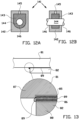
- Figures 12A and 12B show schematic cross-sections of a bearing 141 comprising a bearing housing 142, a lubricant holding member 143, and a shaft 144 arranged in an opening in the bearing 141.
- the side of the opening facing the shaft 144 defines a bearing surface 146.
- porous bronze or iron alloy materials which are impregnated with an oil lubricant as a lubricant providing member in bearings. Such materials are also known as Oilite.
- the bearing housing 142 and the lubricant holding member 143 are integrally formed by means of a three-dimensional printing process as defined in the claims.
- the bearing housing 142 is substantially made form impervious material
- the lubricant holding member 143 comprises a pervious material.
- the bearing housing 142 and the lubricant holding member 143 are made from substantially the same basic material, which basic material is printed as impervious material at the position of the bearing housing 142 and is printed as pervious material at the position of the lubricant holding member 143.
- the bearing housing 142 and the lubricant holding member 143 are made from stainless steel.
- the pervious or porous lubricant holding member 143 can be vacuum impregnated with a lubricant, such as oil, to improve the materials bearing ability.
- a lubricant can be provided to the lubricant holding member 143 via a grease fitting 145 in the bearing housing 142.
- the fitting 145 can also be connected to a source for pressurized gas, which gas acts as lubricant and is distributed around the shaft 144 by the lubricant holding member 143, to form an air bearing.
- Figure 13 is a schematic cross-section of a glue connection comprising at least one element with a porous surface layer. More in particular, figure 13 shows a first planar element 81 and a second planar element 82 which are interconnected by a glue connection. As schematically shown in the enlarged view in figure 13 , at least a part of the outer surface of the first planar element 81 comprises a pervious part 85. The remaining part of the first planar element 81 is made from as impervious material 87. Furthermore, at least a part of the outer surface of the second planar element 82 comprises a pervious part 86. The remaining part of the second element 82 is made from as impervious material 88.
- the pervious parts 85, 86 are arranged to at least partially cover the surfaces where the first planar element 81 and the second planar element are to be glued together.
- the pervious part 85 of the first planar element 81 faces the pervious part 86 of the second planar element 82. Accordingly, when a glue 89 is introduced in-between the first and second planar elements, this glue 89 at least partially penetrates into the pervious parts 85, 86 and bridges the gap between the first and second planar elements 81, 82, and provides a firm interconnection between the first and second planar elements 81, 82.
- the glue 89 is at least partially arranged in the pervious parts 85, 86 a much stronger connection between the first element 81 and the second element 82 is obtained compared with the situation when the first and second planar elements are not provided with pervious parts.
- the peel strength between the first and second planar elements according to the invention is much higher, when compared to a glue connection between a two planar elements without the pervious parts.
- the impervious part 87 and the pervious part 85 of the first planar element 81 are integrally formed by means of a three-dimensional printing process, for example as described above with reference to figure 1 . Also the impervious part 88 and the pervious part 86 of the second planar element 82 are integrally formed by means of a three-dimensional printing process.
- FIG 14 shows a schematic cross-section of a heat exchanger 101 for transferring heat between a first and a second fluid.
- the heat exchanger 101 comprises a main body 102 which is formed as a substantially round tube which extends in a direction along a centre line h (the shown cross-section extends substantially perpendicular to said centre line h).
- the main body 102 comprises a pervious material which allows a first fluid to pass from the inside 105 of the main body 102 to the outside 106 of the main body 102, or vice versa.
- a series of secondary tubes 103 having a surrounding wall 104 made from an impervious material.
- the secondary tubes 103 are configured to allow a second fluid to travel through said secondary tubes 103.
- the surrounding wall 104 of the secondary tubes 103 is impervious in order to prevent mixing of the first and second fluid.
- the main body 102 with said wall of pervious material, the secondary tubes 103 with said walls 104 of impervious material, are integrally formed by means of a three-dimensional printing process as defined in the claims and using a heat conducting material, such as a metal powder.
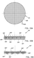
- Figure 15A is a schematic view of a part of an outside wall 121 of a transport device which outside wall 121 is provided with an array of through openings 123 in the surface 122 of the outside wall 121, for example, for boundary layer control.
- the array of through openings 123 may provide adequate boundary layer control, the through openings 123 may become clogged.
- Figure 15B is a schematic side view cross-section of a first alternative part of an outside wall 121' of a transport device comprising an element 128' according to the present invention.
- the element 128' comprises a first layer 125' of an pervious or porous material, which is configured to allow a fluid 129' to flow there through.
- An outer surface 122' of said first layer 125' provides the non-stick surface.
- the element 128' comprises a second layer 124' of an impervious or solid material, which is configured to substantially block a flow of fluid there through.
- the second layer 124' is arranged at a side of said first layer 125' opposite to the outer surface 122'.
- the element 128' comprises a series of ducts 127' which are arranged in between said first and second layer. Said ducts are arranged in fluid connection with said pervious material and are configured for feeding a pressurized fluid to the pervious material.
- the first and second layer are interconnected via a series of studs or ribs 126'.
- the fluid 123' When introducing a pressurized fluid 123' into the ducts 127', the fluid 123' can flow through the first layer 125', which fluid 129' can interact with the boundary layer adjacent the outer surface 122'. For example, by using the fluid 129' the boundary layer may be made more turbulent in order to reduce the draft.
- the first layer 125', the second layer 124', the one or more ducts 127', and the studs or ribs 126' are integrally formed using a three-dimensional printing tool.
- Figure 15C is a schematic side view cross-section of a second alternative part of an outside wall 121" of a transport device comprising an element 128" according to the present invention.
- the element 128" comprises a first layer 125" of an pervious or porous material, which is configured to allow a fluid 127" to flow there through.
- An outer surface 122" of said first layer 125" provides the non-stick surface.
- the element 128" comprises a second layer 124" of an impervious or solid material, which is configured to substantially block a flow of fluid there through.
- the second layer 124" is arranged at a side of said first layer 125" opposite to the outer surface 122".
- the element 128" comprises a series of ducts 126" which are arranged in between said first and second layer. Said ducts 126" are arranged in fluid connection with said pervious material and are configured for feeding a pressurized fluid to the pervious material.
- the first and second layer are substantially integrally formed.
- the fluid When introducing a pressurized fluid into the ducts 126", the fluid can flow through the first layer 125", which fluid 127" can interact with the boundary layer adjacent the outer surface 122". For example, by using the fluid 127" the boundary layer may be made more turbulent in order to reduce the draft.
- the first layer 125", the second layer 124", and the one or more ducts 126" are integrally formed using a three-dimensional printing tool
- Figure 16 shows a schematic cross section of a further example of an element 131.
- the element 131 is a housing for a sensor 132.
- the housing 131 is substantially rotation symmetric with respect to a centre line 139 and comprises a base part 133 which is substantially shaped as a tube with a longitudinal channel 134 which is used for positioning the sensor 132 inside the housing and for accommodating connecting cables 132' from the sensor 132 which connecting cables 132' extend from the sensor 132, along the channel 134 to the outside of said element 131.
- the base part 133 in this example is provided with a flange member 135 for mounting and/or sealing the element 131 against a wall of a reactor or a duct, for example.
- the base part 133 and the flange member 135 are made from an impervious material.
- the housing 131 further comprises a sensor chamber 136 comprising a circumferential wall 137.
- the circumferential wall 137 is arranged to substantially enclosing the sensor 132, and is made from a pervious material to allow a fluid to penetrate into the sensor chamber 136 to come into contact with the sensor which can measure one or more properties or characteristics of said fluid.
- the sensor chamber 136 is provided with support members 138, which are preferably integrally formed with the circumferential wall 137, for holding the sensor 132.
- the housing 131 with the base part 133, the flange member 135, the circumferential pervious wall 137 and the support members, are integrally formed by means of a three-dimensional printing process as defined in the claims. It is noted that the three-dimensional printing process also provides a large freedom to form the housing 131, and in particular circumferential wall 137 of the sensor chamber 136 in any desired shape.
- the circumferential wall 137 can be provide with one or more large openings at desired locations in said wall 137 to allow a certain flow of material to enter into or through the sensor chamber 136.
- the circumferential wall 137 can be provided with impervious parts at desired locations in said wall 137 to block a fluid to enter the sensor chamber 136 at said locations.
- integrally formed pervious and impervious parts can have big advantages when compared to elements where the pervious parts and impervious parts are manufactured separately and are connected to each other afterwards.
- integrally formed parts are highly advantageous in view of hygienic requirements. Integrally formed parts are more easy manufacture and also more easy to clean.
- multipart element usually comprises a seam or joint where the parts of the element are connected.
- a seam or joint where the parts of the element are connected.
- residual substances accumulate which can be difficult to remove.
- Such residual substances may therefor become a source for contamination and pose a hygienic hazard.
- a seamless or jointless transition between a pervious and impervious part, as provided by the present invention is highly advantageous.
- the invention relates to a method and to a computer readable medium in accordance with the appended claims.
Landscapes
- Engineering & Computer Science (AREA)
- Chemical & Material Sciences (AREA)
- Materials Engineering (AREA)
- Mechanical Engineering (AREA)
- Manufacturing & Machinery (AREA)
- Physics & Mathematics (AREA)
- Optics & Photonics (AREA)
- Life Sciences & Earth Sciences (AREA)
- General Engineering & Computer Science (AREA)
- Combustion & Propulsion (AREA)
- Fluid Mechanics (AREA)
- Food Science & Technology (AREA)
- Ocean & Marine Engineering (AREA)
- Transportation (AREA)
- Aviation & Aerospace Engineering (AREA)
- Forests & Forestry (AREA)
- Powder Metallurgy (AREA)
Description
- The invention relates to a method for producing an element with both pervious and non-pervious parts by means of a three-dimensional printer.
- A non-stick surface is a surface engineered to reduce the ability of other materials to stick to it. An area where non-stick surfaces is frequently used is the food industry. For example in industrial bakery technology for the production of bread, baguette, cake, ciabatta, pizza, puff pastry, rolls, buns and cookies, pieces of dough transported to and handled at various handling stations on top of proofing trays and/or baking trays. Such trays are commonly provided with anti-adhesion or non-stick coating based on fluoropolymers or rubber silicones.
- A disadvantage of using such known anti-adhesion or non-stick coatings is, that due to wear during the use of such trays, abrasion or damaging of the non-stick coating may occur and regular re-coating of the trays is required.
-
WO 2004/002229 A2 discloses a moulding device for moulding a meat mass. The moulding device comprises a removable insert comprising a mould cavity for moulding the meat mass, wherein the removable insert is prepared from a sintered porous material. The document further discloses that the moulded meat mass may be eliminated from the removable insert by applying a pressurized fluid via the porous material between a boundary of the mould cavity and the moulded meat mass. -
US 2014/0010908 A1 discloses a method for manufacturing a three dimensional object via selective laser sintering. An adjustment of an irradiation energy applied by a light beam is used by the method to form a low-density solidified portion, an intermediate-density solidified portion and a high-density portion in the object. The document further discloses that the intermediate and low-density portions are porous, and when arranged at a surface of the object the intermediate-density solidified portion, preferably in combination with the low-density portion, can be used as a gas vent of a metal mould. - It is an object of the present invention to least partially solve the above identified disadvantage and/or to provide an alternative element with non-stick surface. It is further an object of the present invention to provide a method for producing such an element, preferably using a three-dimensional printing technique.
- According to a first aspect, the invention provides a method for producing an element with both pervious and non-pervious parts, wherein the pervious part is integrally formed with the impervious part, wherein the method comprises a three-dimensional printing process comprising the steps of:
- providing a layer of granular material,
- directing a laser beam at printing positions on or in said layer of granular material using first or second set of printer settings of said three-dimensional printer, wherein the set of printer settings of the printing process are changed from the first set of printer settings to the second set of printer settings, or vice versa, during the printing of said layer,
- wherein the first set of printer settings are configured such that during said printing process, particles of said granular material are partially fused together to form a material wherein a space between the particles is at least partially maintained to form the pervious part,
- wherein the second set of printer settings are configured such that during said printing process, particles of said granular material are fused together to form a material wherein a space between the particles of the granular material is substantially removed to form the impervious part,
- wherein the first set of printer settings is configured to obtain a pervious part in which the space between the particles in the pervious part is at least partially interconnected to allow a fluid to flow through the pervious part, and such that the outer surface of the pervious part provides a non-stick surface, and
- wherein the first printer settings are configured such that the pervious part comprises pores and material between pores with a thickness smaller than a spot diameter of the laser beam at the printing position.
- In particular, the material between adjacent pores has a minimum thickness smaller than the spot diameter of the laser beam at the printing position or smaller than the line width of the printing process. The method of the present invention utilizes a method in which a laser beam is directed on or in a layer of granular material. In this application, a granular material is a conglomeration of discrete solid particles. In the layer of granular material, the particles are loosely arranged in the layer such that there is an amount of space between the particles which is sometimes called the inter-particle void volume. For the three-dimensional printing method according to the invention, the particles preferably have a size from about 1 µm to 500 µm, preferably from about 10 µm to 100 µm, more preferably from about 10 µm to 45 µm. As indicated above, the pervious part is formed by configuring the three-dimensional printer such that the space between the granular particles which are used in the three-dimensional printing process, is at least partially maintained. The size of the space between the granular particles depends, inter alia, on the size of the particles; using 'large' granular particles for printing the pervious material results in a pervious material with relatively large pores, and using 'small' granular particles for printing the pervious material results in a pervious material with relatively small pores. Accordingly, the size of the pores in the pervious material can be controlled to a certain extent, inter alia, by selecting granular particles of the right size.
- In the method of the invention, the laser beam is preferably directed on or near the layer to an exposure position. At the exposure position the granular material is heated and the particles are fused together.
- By carefully configuring the three dimensional printer to a first set of printer settings, the particles of said granular material are partially fused together to form a material wherein the inter-particle void volume is at least partially preserved to form a pervious or porous part. Accordingly, since the inter-particle void volume is at least partially preserved, the printed material as obtained using the first set of printer settings has a lower density than the density of the particles.
- In addition, by carefully configuring the three dimensional printer to a second set of printer settings, the particles of said granular material are substantially completely fused together to form a material wherein the space between the particles of the granular material is substantially removed to form the impervious part. Accordingly, the printed material as obtained using the second set of printer settings has a high density, which may substantially be equal to the density of the particles or to a density of a solid made from the same material as the particles.
- According to the invention, the printing tool is configured to change the printer settings during the printing of an element. By re-configuring the printing settings during the printing process, integrally formed pervious and impervious parts can be produced during the printing of the layer of the element. Accordingly, the present invention provides a method for integrally forming an element with low density and high density parts.
- Since the pervious or porous structures are obtained by partially fusing the particles of said granular material together, fine pervious or porous structures can be manufactured with a printing tool with a large line width. In addition, with that same printing tool and with the same large line width, also impervious structures are manufactured, which are integrally formed with the pervious structures.
- It is noted that the term element relates to a mechanical structure which is substantially made from the same, single material. Particularly commercially interesting are elements which are substantially made from a metallic material. Examples of such metallic materials are, Stainless Steel, Titanium, and Tantalum. However other metallic materials or alloys may also be applied. In case the metallic element is made from one and the same metallic material, it may also be referred to as a monometallic element.
- In order to produce such a metallic element in a three-dimensional printing tool, a granular metal material or a metal powder is provided in a bed with a substantially flat upper side, which metal granular material is selectively melted by a laser beam at the positions where the element needs to be created. Subsequently, a new thin layer of metal granular material is provided on top of the upper side of the bed, which new thin layer is again selectively melted by the laser beam at the positions where the element needs to be created. By repeating this step, the element is built up layer by layer to produce the desired metallic element.
- By changing the processing parameters during the selective melting of the metal granular material in a thin layer of said metal granular material by the laser beam, pervious and impervious parts can be produced which are arranged adjacent in the layer of metal granular material. By changing the process parameters between the processing of subsequent layers of metal granular material, pervious and impervious parts can be produced which are arranged adjacent in a direction substantially perpendicular to the layers of metal granular material. By combining these processes a three-dimensional metallic element can be manufactured comprising three-dimensional structures or volumes with a pervious part and an impervious part which are integrally formed.
- It is noted that the same principle may also be applied using other types of materials, in particular synthetic or plastic materials.
- It is noted that in this application, the word 'pervious' means 'able to be penetrated'.
- It is further noted that the first set of printer settings are configured such that during said printing process, particles of said granular material are partially fused together to form a material wherein a space between the particles is at least partially maintained to form a material with is comparable in structure with a sintered material.
- Accordingly, the first set of printer settings is configured to obtain a pervious or porous part in which the inter-particle void volumes are at least partially interconnected or intercommunicating to allow a fluid to flow through the pervious or porous part. The method of the present invention can provides elements with integrally formed impervious and pervious parts, wherein the pervious parts are configured to allow a fluid to flow there through, and wherein the impervious parts preferably are configured to restrict or at least partially confine the fluid in the pervious part and/or to restrict or at least partially confine the flow of said fluid through said pervious part.
- In an embodiment, the method is configured for producing an element comprising a non-stick surface for substantially cleanly removing a product which is arranged against said non-stick surface,
- wherein the element comprises a first layer of an pervious material, wherein the pervious material is configured to allow a fluid to flow there through, and wherein an outer surface of said first layer provides the non-stick surface, and
- wherein the element comprises a second layer of an impervious material, wherein the impervious material is configured to substantially block a flow of the fluid there through, and wherein the second layer is arranged at a side of said first layer opposite to the outer surface,
- wherein the element comprises one or more ducts or chambers which are arranged in said first layer or in between said first and second layer, wherein said one or more ducts or chambers are arranged in fluid connection with said pervious material and are configured for feeding a pressurized fluid to the pervious material,
- wherein at least the first layer is formed by sintering a powder material preferably by using a three-dimensional printing tool.
- Commonly known non-stick coatings are based on materials which provide a very smooth surface and a low coefficient of friction. The present invention provides a fundamentally new concept and design of non-stick surfaces, by using an layer of pervious or porous material.
- According to the present invention, the element is configured to feed a pressurized fluid to the pervious material. This pressurized fluid is transmitted through the pervious material of the first layer and exits the first layer at the outer surface. Accordingly, the pressurized fluid can act on a product which is placed against or onto the outer surface. When the product needs to be removed from the outer surface, the one or more ducts or chambers are provided with pressurised fluid and the pressurized fluid pushes the product away from the outer surface, which can provide a substantially clean removal of the product, substantially without leaving any residual product behind on the outer surface. Accordingly, the outer surface of the element thus provides a non-stick surface.
- In addition, the non-stick properties of the outer surface of the element can be switched on and off by controlling the pressure of the fluid.
- According to the invention, the first layer is formed by sintering a powder material, preferably by using a three-dimensional printing tool. Sintering of a powder material provides a pervious or porous layer with small pores having a diameter which is generally smaller than the diameter of the powder particles used for producing the pervious material. Preferably, the size of the powder particles is selected such that the pores in the pervious material are large enough to allow a fluid to flow through the pervious material, and are small enough such that the material of the product substantially does not penetrate into the pores of the pervious material.
- At least the first layer is preferably formed using a three-dimensional printing tool, which allows a very accurate shaping of the outer surface. When using laser additive manufacturing as a three-dimensional printing tool, the laser used for sintering the powder particles can be focussed to a very small light spot which enables to manufacture very small features with sharp transitions.
- In an embodiment, at least the first layer, the second layer and the one or more ducts or chambers are integrally formed using a three-dimensional printing tool. The three-dimensional printing tool is used to create pervious and impervious material and to create the one or more ducts or chamber. Accordingly, the first layer, the second layer and the one or more ducts or chambers are integrally formed to provide the element of the present invention.
- In an embodiment, the first layer and/or the one or more ducts or chambers are configured to distribute the fluid over the pervious material, preferably to distribute the fluid over the non-stick surface, more preferably to evenly distribute the fluid over the non-stick surface. By distributing the fluid over the pervious material, the non-stick properties of the outer surface can be provided substantially over the whole outer surface.
- In an embodiment, the one or more ducts or chambers extend in a direction substantially parallel to the non-stick surface. Accordingly, the one or more ducts or chambers assistance to distribute the fluid over the first layer.
- In an embodiment at least the first layer and/or the one or more ducts or chambers are configured to provide substantially the same pressure drop of the pressurised fluid over the pervious material in a fluid path from the one or more ducts or chambers to the non-stick surface. In an embodiment, at least the first layer and/or the one or more ducts or chambers are configured to provide substantially the same pressure of the pressurised fluid at the non-stick surface. By configuring the first layer and/or the one or more ducts or chambers to provide the same pressure drop over the pervious material and/or to provide the same pressure of the fluid at the non-stick surface, a force or pressure exerted by the fluid on the product is substantially constant over the substantially the whole non-stick surface.
- In an embodiment, the invention provides an assembly comprising an element or an embodiment thereof as described above, and an input member for connecting a source for providing a pressurized fluid to the one or more ducts or chambers of the element, wherein the assembly is configured for providing the pressurized fluid to substantially nullify an adhesion of a product to the non-stick surface of the element.
- In an embodiment, the assembly further comprises a second input for connecting a vacuum source, such as a suction pump, for reducing the pressure in the one or more ducts or chambers of the element. By using a vacuum source for reducing the pressure in the one or more ducts or chamber of the element, the product can even be pulled against the outer surface for actively holding and/or fixing the product on the outer surface, for as long as the suction pump is active. When the product needs to be removed from the outer surface, the source for providing the pressurized fluid is activated to push the product away from the outer surface and activate the non-stick properties of the outer surface to provide a substantially clean removal of the product.
- In an embodiment, the element is a part of a moulding device, preferably for moulding three-dimensional products from a mass of material, preferably a mass of food material, more preferably a dough material. The element of the present invention is particularly suitable for use in a moulding device. The clean removal of the product from the mould is highly advantageous. However, it is undesirable that the product falls out of the mould inadvertently due to the non-stick. The element of the present invention allows to switch the non-stick properties, which can be activated at the instant that the product must be removed from the mould.
- In an embodiment, the moulding device comprises a rotatable drum, wherein the outer circumference of said rotatable drum is provided with a series of moulding cavities, wherein at least one of said moulding cavities comprises the element, wherein the non-stick surface of the element is arranged to provide an internal surface of said at least one of said moulding cavities.
- In an embodiment, the moulding device comprises a disk or a plate, wherein the outer surface of said disk or plate is provided with a series of moulding cavities, wherein at least one of said moulding cavities comprises the element, wherein the non-stick surface of the element is arranged to provide an internal surface of said at least one of said moulding cavities.
- In an embodiment, the element comprises a series of ducts, wherein the assembly comprises a control device for controlling the feeding of pressurized fluid to individual ducts or to a set of ducts of said series of ducts. This embodiment allows to stepwise feeding pressurised fluid to the ducts, and thus to activate the non-stick properties in a stepwise manner over the non-stick surface. Accordingly, the release of the product from the non-stick surface can be established in a stepwise manner, which allows a highly controlled release of the product from the outer surface of the element.
- In an embodiment, the element is part of a cutting device, preferably wherein the non-stick surface of the element is part of a cutting blade of said cutting device. Accordingly the cutting device is provided with a non-stick surface for substantially cleanly cutting a product, in particular without leaving any residual product behind on the cutting device.
- In addition, when not in use for cutting, a cleaning component, such as hot pressurized steam, can be supplied to the one or more ducts or chambers, which cleaning component is transmitted through the first layer of pervious material in order to clean or even sterilize the outer surface of the cutting device.
- In an embodiment, the element is part of a storage container or a hopper, preferably wherein the non-stick surface of the element is part of an internal wall of the storage container or the hopper. In an embodiment, the element is part of a conveyor system, in particular a conveyor system comprising pipes, ducts or troughs, wherein the non-stick surface of the element is part of an internal wall of one of the pipes, ducts or troughs. By using the element of the present invention as part of a storage container, hopper or conveyor system, at least part of the internal wall of said container, hopper or conveyor system is provided with a non-stick surface, which allows to cleanly remove or transport the product out of the container or hopper, or to transport the product through the pipes, ducts or troughs of the conveyor system, substantially without leaving any residual product behind in the container, hopper or conveyor system.
- In an embodiment, the element is part of a bearing, preferably wherein the non-stick surface of the element is part of an internal wall of the bearing which internal wall, in use, faces a moving member such as a rotating and/or translating shaft or shaft holding member. By providing a fluid via the one or more ducts or chambers to the non-stick surface, the friction between the internal wall of the bearing and a moving member inside the bearing can be reduced. The fluid may comprise a lubricant, preferably an oil lubricant.
- Alternatively the fluid may comprise a pressurized gas to provide a low friction and/or load-bearing interface between the internal wall and the moving member. Gas-lubricated bearings are classified in two groups, depending on the source of pressurization of the gas film providing the load-carrying capacity:
- Aerostatic bearings: the gas is externally-pressurized (using a compressor or a pressure tank) and injected in the clearance of the bearing via the pervious material of the first layer.
- Aerodynamic bearings: the gas between the internal wall and the moving member is pressurized by the relative velocity between and/or the shape of the static and moving surfaces in the bearing. Aerodynamic bearings are self-acting and do not require an external input of compressed gas. However, when the relative velocity between the moving surface decreases, the pressure of the gas between the internal wall and the moving member decreases. By providing an Aerodynamic bearing with the element of the present invention, additional gas pressure can be provided via the pervious material of the first layer during starting or stopping of the moving member.
- In an embodiment, the element is part of a boundary layer control system on a transport device, such as an aircraft, a ship or a car, wherein the element is arranged such that the outer surface of the element is part of the outer surface of the transport device. Such a boundary layer control system allows controlling the behaviour of fluid flow boundary layers at the outer surface of the transport device.
- It may be desirable to reduce flow separation on fast vehicles to reduce drag. Boundary layer separation is generally undesirable in aircraft high lift coefficient systems and jet engine intakes. Laminar flow produces less skin friction than turbulent but a turbulent boundary layers are more resistant to separation.
- In order to control the behavior of fluid flow boundary layers, a pressurized fluid can be introduced through the pervious material of the element into the fluid flowing around the transport device. Alternatively, or additionally the low momentum layer at the surface of the transport device can be sucked away through the pervious material of the element.
- Recent developments in additive manufacturing processes, such as three-dimensional printing, have made it possible to produce elements with structures and designs which could not be produced in a conventional way. One of such newly produced elements comprises porous and solid structures which can be integrally formed using three-dimensional printing. For example,
WO2017/117527A1 discloses a laser additive manufacturing process which can be used to create porous structures, solid structures, and structures which have both porous and solid portions that are integrally formed together. - A method for producing an element with at least an impervious part and a pervious part is disclosed, wherein the pervious part is integrally formed with the impervious part by means of a three-dimensional printing process using a laser beam focussed to a spot diameter at a printing position, wherein parameters of the three-dimensional printing process when printing the pervious part are different from parameters of the three-dimensional printing process when printing the impervious part. Preferably, the parameters of the three-dimensional printing process when printing the pervious part are arranged such that the pervious part comprises pores and material between adjacent pores, wherein the material between adjacent pores has a minimum thickness smaller than the spot diameter of the laser beam at the printing position or smaller than the line width of the printing process.
- In an embodiment, the parameters comprise an irradiation power (W) by the laser beam at the printing position, preferably wherein the irradiation power for printing the pervious part is lower than the irradiation power for printing the impervious part. Accordingly, during the three-dimensional printing process, the power of the laser beam is changed from a first value for printing impervious material to a second value for printing pervious material, or vice versa.
- In an embodiment, the parameters comprise a scanning speed with which the laser beam is scanned during the three-dimensional printing process, preferably wherein the scanning speed for printing the pervious part is higher than the scanning speed for printing the impervious part. Accordingly, during the three-dimensional printing process, the scanning speed of the laser beam is changed from a first value for printing impervious material to a second value for printing pervious material, or vice versa.
- In an embodiment, the parameters comprise a distance between adjacent scanning lines of the laser beam during the three-dimensional printing process, preferably wherein the distance between adjacent scanning lines for printing the pervious part is higher than the distance between adjacent scanning lines for printing the impervious part. Accordingly, during the three-dimensional printing process, the distance between adjacent scanning lines is changed from a first value for printing impervious material to a second value for printing pervious material, or vice versa.
- In an embodiment, the parameters comprise a distance between a focus position of the laser beam and the printing position, preferably wherein the distance between the focus position of the laser beam and the printing position for printing the pervious part is higher than the distance between the focus position of the laser beam and the printing position for printing the impervious part. Accordingly, during the three-dimensional printing process, the distance between a focus position of the laser beam and the printing position is changed from a first value for printing impervious material to a second value for printing pervious material, or vice versa. By moving the focus position away from the printing position, the layer of granular material is arranged out of focus and the energy of the laser beam is spread over a larger area at the printing position. So in fact, the energy density at the printing position is lowered when the focus position is moved away from the printing position.
- It is noted, that in the printing process of the present invention, substantially the whole area of the pervious part is irradiated by the laser beam, which irradiation results in the formation of pervious or porous material within the irradiated parts. This is completely different from the technology of creating porous structures by printing a set of repeating hollow polyhedrons with at least partially open faces as described in the prior art, wherein only the positions where struts need to be created are irradiated by the laser beam.
- According to a second aspect, the invention provides a computer-readable medium comprising computer-executable instructions adapted to cause a three-dimensional printing tool to perform a method as defined by
claim 1. - The invention will be elucidated on the basis of an exemplary embodiment shown in the attached drawings, in which:
-
Figure 1 is a schematic cross-section of a three-dimensional printing tool, -
Figure 2 is a schematic cross-section of a first example of a part of an element of the present invention, -
Figure 3 is a schematic cross-section of a second example of a part of an element of the present invention, -
Figure 4 is a schematic cross-section of a third example of a part of an element of the present invention, -
Figure 5 is a schematic cross-section of a fourth example of an element of the present invention, -
Figure 6A is a schematic cross-section of a part of a moulding device for moulding three-dimensional products from a mass of material device comprising an element of the present invention, -
Figure 6B is an enlarged view of an first alternative part of a moulding device offigure 6A . -
Figure 7 is an enlarged view of a part of a second alternative part of a moulding device offigure 6A , -
Figure 8 is a schematic cross-section of a mould for a vacuum forming process, -
Figure 9A and 9B are schematic cross-sections of a cutting device according to the present invention, -
Figure 10A shows a storage container for holding and dispensing granular material, -
Figure 10B is a schematic cross-section of a part of the side wall of the storage container offigure 10A according to the present invention, -
Figure 10C is a schematic cross-section of a part of an alternative side wall of the storage container offigure 10A according to the present invention, -
Figure 11A is a schematic cross-section of a transport tube with an wall according to the present invention, -
Figure 11B is a schematic cross-section of a transport trough with a wall according to the present invention, -
Figures 12A and 12B are schematic cross-sections of a bearing comprising a bearing housing of an impervious material and an internal wall of a pervious material according to the present invention, -
Figure 13 is a schematic cross-section of a glue connection comprising at least one element according to the present invention, -
Figure 14 is a schematic cross-section of a heat exchanger according to the present invention, -
Figure 15A is a schematic view of a part of an outside wall of a transport device which outside wall is provided with an array of through openings, for example, for boundary layer control, -
Figure 15B is a schematic side view cross-section of a first alternative part of an outside wall of a transport device comprising an element according to the present invention, -
Figure 15C is a schematic side view cross-section of a second alternative part of an outside wall of a transport device comprising an element according to the present invention, and -
Figure 16 is a schematic cross-section of a housing for a sensor according to the present invention, -
Figure 1 shows a schematic cross-section of a three-dimensional printing tool 1. In order to produce an element, in particular a metallic element, of the present invention in the three-dimensional printing tool 1, agranular material 2 of the material, in particular a metal powder, is provided in abed 3 with a substantially flatupper side 4. The granular material may for example be a Stainless Steel granular material with a grain diameter in a range of 10 - 65 µm. - In order to selectively melt said Stainless Steel
granular material 2, the three-dimensional printing tool 1 comprises alaser 5 which produces alaser beam 6 which is focussed down to a spot size of approximately 100 micrometres, and with a substantial Gaussian intensity profile. The focus position is arranged at or near theupper side 4 of thebed 3 of metal powder. - The
laser 5 and/or thelaser beam 6 is scanned XY over the flatupper side 4 of thebed 3 of Stainless Steel granular material and is switched on and off in order to selectively melting the metalgranular material 2 at the positions where the element needs to be created. It is noted that thelaser beam 6 is moveable in a direction parallel to the direction of the cross-section, and in a direction perpendicular to the direction of the cross-section. Accordingly, thelaser beam 6 can be scanned over a plane spanned by theupper side 4 of thebed 3. - As schematically shown in
figure 1 , thebed 3 ofgranular material 2 is arranged on top of abuilding platform 7. In a first step of the production process, thebuilding platform 7 is covered by a layer ofgranular material 2. In a second step, thelaser beam 6 is scanned over the layer to selectively expose the layer of granular material at the positions where the first layer of the element needs to be created. In a third step thebuilding platform 7 is lowered Z and a new layer ofgranular material 2 is applied. By subsequently repeating the second and third steps, the element is built up layer by layer, until the element is completely printed. The completely printed element and thebuilding platform 7 are then removed from the three-dimensional printing tool 1 and the element is separated from thebuilding platform 7. If necessary, the element can be subjected to a posttreatment and/or a finishing process. - When using a laser power of 150 Watt, a scanning speed of 1000 mm/s, a distance between adjacent scanning lines as scanned by the laser of 0,1 mm, and positioning the
upper side 4 of thebed 3 in the focus of thelaser beam 6, a substantially impervious or solid Stainless Steel element can be produced. Typically, the inventor has found that when providing an energy density of approximately 70 Joule/mm3 or higher to a bed of Stainless Steel powder with a grain size in a range between 10µm and 65 µm, substantially impervious or solid Stainless Steel material is obtained. Using an energy density below 70 Joule/mm3 usually yields a pervious Stainless Steel material. - However, in order to produce a non-stick surface according to the present invention fine pervious or porous regions can be obtained by changing the printer settings of the three-dimensional printing process. For example:
Setting 1 Setting 2Setting 3Laser Power [Watt] 100 100 50 Scanning velocity [mm/s] 1000 1000 1500 Out of focus [mm] 0 0 1 Distance adjacent scanlines [mm] 0.1 0.15 0.1 Porosity 2 % 5 % 10% laser beam 6 and the printing position at theupper surface 4 of thebed 3 ofgranular material 2, which parameter is '0' when the laser focus is arranged at theupper surface 4 of thebed 3. When the laser focus is moved away from theupper surface 4 and is arranged spaced apart at a distance from theupper surface 4 of thebed 3 ofgranular material 2, the diameter of thelaser beam 6 at theupper surface 4 is increased and the Power of thelaser beam 6 is spread over a larger surface area. - It is noted that the porosity as presented in this list is determined by measuring the density of the pervious metallic elements.
- Preferably, the
laser beam 6 is directed at printing positions on or in said layer ofgranular material 2 using first or second set of printer settings of said three-dimensional printer 1, wherein the set of printer settings of the printing process are changed from the first set of printer settings to the second set of printer settings, or vice versa, during the printing of said element. - The first set of printer settings are configured such that during said printing process, particles of said
granular material 2 are partially fused together to form a material wherein a space between the particles is at least partially maintained to form thepervious part 8. An outer surface of saidpervious part 8 provides the non-stick surface. The pores between the partially fused particles of the granular material are typically smaller than the diameter of the particles. - The second set of printer settings are configured such that during said printing process, particles of said
granular material 2 are fused together to form a material wherein a space between the particles of the granular material is substantially removed to form theimpervious part 9. - Using a change of the printer settings during the production of an element in a three-
dimensional printing tool 1, provides a method for producing an element which comprises integrally formed pervious 8 and impervious 9 parts with highly specific and reproducible structures for many possible applications. -
Figure 2 schematically shows a cross section of a part a first example of an element with both pervious and non-pervious parts. In particular,figure 2 shows a part of awall 10 which is produced by subsequently printinglayers 11 of a material using a three-dimensional printing tool. By changing the printer settings during the printing of each one of thelayers 11,pervious parts 13 andimpervious parts 12 are produced adjacent to each other. By arranging thepervious parts 13 of eachlayer 11 at least partially on top of each other, apervious part 13 is obtained that extends over the whole or substantially the whole thickness d of thewall 10. Theimpervious parts 12 are arranged adjoining saidpervious part 13 in a direction along thewall surface 15. The pervious orporous part 13 extend over the whole thickness D of thewall 10, this pervious orporous part 13 is preferably configured to allow fluids such as a liquid or a gas to pass through 14 from one side of thewall 10 to the other side. Accordingly, thepervious part 13 provides a passage for a fluid, which passage is in a direction transverse to the thickness d of thewall 10 delimited byimpervious parts 12. -
Figure 3 schematically shows a cross section of a part a second example of an element with pervious and impervious parts. In particular,figure 3 shows a part of awall 20 which is produced by subsequently printinglayers 21 of a material using a three-dimensional printing tool. By changing the processing parameters during the printing ofsubsequent layers 21,pervious parts 23 andimpervious parts 22 are produced as a pervious or porous layer on top of or below an impervious layer. As schematically shown infigure 3 , thepervious part 23 and theimpervious part 22 are arranged adjoining in a direction substantially perpendicular to theouter wall surface 25. Accordingly, thewall 20 as a whole is impervious for fluids or gasses from one side of the wall to the other side. - Preferably, the pervious or
porous layer 23 is arranged at anouter wall surface 25. In addition, thepervious part 23 is preferably configured to allow absorption of other materials. For example, thepervious part 23 is configured to provide adsorption of a lubricant, in particular a liquid lubricant, in order to provide a low frictionouter surface 25. Alternatively, thepervious part 23 is configured to provide adsorption of an adhesive, in particular a liquid adhesive which at least partially penetrates thepervious part 23 and which provides a strong adhesion between the adhesive and theouter surface 25 of thewall 20. -
Figure 4 is a schematic cross-section of a third example of a part of an element with pervious and impervious part. In particular, this figure shows a part of awall 30 which is produced by subsequently printinglayers 31 of a material using a three-dimensional printing tool. By changing the printer settings during the printing of each one of thelayers 31 and during the printing ofsubsequent layers 31,pervious parts 33 andimpervious parts 32 are produced. - As schematically indicated in
figure 4 , thewall 30 comprises afirst layer 37 comprising impervious material, and asecond layer 38 comprising both pervious 33 and impervious 32 material. Thefirst layer 37 and thesecond layer 38 extend in a direction substantially parallel to theouter wall surface 39, whichouter surface 39 provides the non-stick surface. Thesecond layer 38 is arranged to provide saidouter wall surface 39. Thefirst layer 37 is arranged at a side of saidsecond layer 38 opposite to theouter wall surface 39. - As schematically shown in
figure 4 , thewall 30 comprises one ormore ducts second layer 38 for providing a supply or drain conduit for a liquid, or a feed or exhaust conduit for a gas. In particular, theducts second layer 34 at a position spaced apart from theouter wall surface 39. Theducts wall 30, debouche at the interface between thefirst layer 37 and thesecond layer 38, and are at least partially arranged in saidfirst layer 37. - As furthermore shown in
figure 4 , theduct 34 may extend inside thewall 30 in a direction substantially parallel to theouter wall surface 39. In addition or alternatively, theduct 35 may extend inside thewall 30 in a direction substantially perpendicular to theouter wall surface 39. The pervious orporous part 33 is preferably configured to allow fluids (liquids or gasses) when supplied via theducts pervious part 33 at theouter wall surface 39. Alternatively, the pervious orporous part 33 is configured to allow to drain or extract fluids from the saidpervious part 33 via theducts outer wall surface 39 via the pervious orporous part 33 and theducts - It is noted that the exemplary elements of
figures 2, 3 and 4 are preferably metallic elements, more preferably monometallic elements, which can be manufactured from, for example, Stainless Steel using the three-dimensional printing tool 1 and the printer settings as described above. - A more elaborate fourth example of a metallic element of the present invention is shown in
figure 5 . In particular,figure 5 shows a schematic cross-section of ametallic element 40 according to the present invention. Themetallic element 40 comprisesimpervious walls 44, 44' and apervious wall 43, whichwalls chamber 42. In the impervious wall 44' opposite thepervious wall 43, anopening 45 is provided, whichopening 45 can be connected to a fluid supply or to a fluid pump device (not shown). Themetallic element 40 is preferably integrally formed using a three-dimensional printing tool, and can be used for many different applications, for example: - a. The
pervious wall 43 can be utilized as a non-stick surface for substantially cleanly removing a product which was arranged against theouter face 47 of theprevious wall 43. Theopening 45 is in this case connected to an air supply to provide pressurised air inside thechamber 42. The pressurised air is transmitted through thepervious wall 43 and acts on a product which is placed against or onto theouter face 47 of theprevious wall 43. When the product needs to be removed, thechamber 42 is pressurised, and the pressurised air pushes the product away from theouter face 47 of thepervious wall 43, which can provide a substantially clean removal of the product, substantially without leaving any residual product behind on theouter face 47. - b. The
pervious wall 43 can also be utilized as a suction area for holding a product, preferably a substantially flat product. Theopening 45 is than connected to a vacuum pump in order to reduce the air pressure inside thechamber 42. The reduced air pressure inside thechamber 42 is transmitted by thepervious wall 43 and acts on a product which is placed against thepervious wall 43. Accordingly, theouter face 47 of thepervious wall 43 acts as a suction area to hold the product against thepervious wall 43. - c. The
outer face 47 of thepervious wall 43 can also be utilized as a cleaning surface, for example for cleaning components or an assembly for the food industry. Theopening 45 can be connected to a supply for a pressurised cleaning agent, such as hot pressurised steam. The steam is transmitted through thepervious wall 43 which is arranged near to or adjacent the components or assembly which needs to be cleaned, so that the steam coming out of theouter surface 47 of thepervious wall 43 can perform a cleaning action on the components or assembly. - d. The
pervious wall 43 can also be a part of a wall between moving parts of a bearing. Theopening 45 is preferably connected to a supply for a lubricant. The lubricant, as supplied to thechamber 42, is transmitted through thepervious wall 43 to provide lubrication to theouter face 47 of thepervious wall 43 to reduce friction between the moving parts. - It is to be understood that the above examples a, b, c and d are included to illustrate the operation of the fourth example and are not meant to limit the scope of the example according to the invention.
-
Figures 6A schematically shows a part of a moulding device for moulding three-dimensional products from a mass of material, for example a mass of foodstuff starting material, such as dough mass for the manufacturing of cookies for example. The moulding device comprises arotatable drum 51 which is driven by an associated drive motor (not shown). The outer circumference of saidrotatable drum 51 is provided with a series ofmoulding cavities 52 which define the shape of the products which are to be produced. Adjacent to thedrum 51, a fillingdevice 53 is arranged, which fills themould cavities 52 which move past the fillingdevice 53 with the mass. Theproducts 54 arranged in thecavities 52 are removed from the cavity in questions at a release position located downstream the fillingdevice 53, and fall onto aconveyor device 55 for transporting theproducts 54 away from the moulding device. - In order to assist in the removal of the
products 54 from acavity 52, the wall of thedrum 51 at thecavities 52 is made from apervious material 51" which is permeable for a fluid, such as pressurized air, while at least the part of thedrum 51 surrounding thecavity 52 is made from an impervious material 51'. According to the present invention, thepervious material 51" is made using particles of granular material which are fused together to form a material wherein a space between the particles is at least partially maintained and is at least partially interconnected to allow a fluid to flow through thepervious material 51". In the impervious material 51', particles of said granular material are substantially completely fused together to form a material wherein a space between the particles of the granular material is substantially removed. When theproduct 54 needs to be removed from themoulding cavity 52, the chamber orduct 56 is pressurised, and the pressurised air pushes theproduct 54 away from the outer surface of thepervious wall 51", which provide a substantially clean removal of theproduct 54, substantially without leaving any residual product behind in themoulding cavity 52. Accordingly themoulding cavity 52 is provided with a non-stick surface according to the present invention. - It is noted that in the example shown in
figure 6A theimpervious parts 51 and thepervious parts 51" of the moulding device are integrally formed, preferably by means of fusing particle of a granular material in a three-dimensional printing process. -
Figure 6B schematically shows an enlarged view of a part of an alternative example of a moulding device not according to the claimed invention. In this alternative example, thepervious part 51" is separately manufactured, preferably using a three-dimensional printing process. The impervious part 51' of the moulding device can be manufactured using conventional methods or also using a three-dimensional printing process. Thepervious part 51" is inserted in the impervious part 51' to provide the moulding device. Preferably, aseal 59 such as an 'O'-ring is provided between thepervious part 51" and the impervious part 51', as schematically shown infigure 6B . - In both the example shown in
figures 6A and 6B , thepervious part 51" extends over the whole or substantially the whole wall thickness of the outer wall at themoulding cavity 52, and the impervious part 51'is arranged adjoining saidpervious part 51" in a direction along the outer wall surface of thedrum 51. - The
pervious material 51" is provided with pores having a diameter which is generally smaller than the diameter of the granular material used for producing thepervious material 51". When using granular material comprising particles with a diameter in a range from 10 to 65 µm, the pores in thepervious material 51" are large enough to allow a gas, such as pressurized air, to flow through thepervious material 51", and are small enough such that the mass of material substantially does not penetrate into the pores of thepervious material 51". - At the inner side of the
drum 51, adjacent to thepervious material 51", aduct 56 is provided. Theduct 56 in this example is formed by an innerconcentric wall 57 and tworadial walls 58 which connect the innerconcentric wall 57 to the outer wall of thedrum 51. The outer wall of the drum 51 (except for the pervious part at the cavity 52), the innerconcentric wall 57 and the tworadial walls 58 are integrally formed by means of a three-dimensional printing method and are made to comprise impervious material 51' so that theduct 56 is configured for guiding a gas through theduct 56 in a substantial longitudinal direction of thedrum 51. Accordingly, a pressurised fluid can be fed to theduct 56, which fluid is distributed over thepervious material 51" of themoulding cavity 52 associated with saidduct 56, and a through-flow of the fluid through thepervious material 51" can exert a force to a product in themoulding cavity 52 such that theproduct 54 is removed out of themoulding cavity 52, preferably when themoulding cavity 52 is facing theconveyor device 55. In addition or alternatively, theduct 56 can be connected to a vacuum source, such as a suction pump, which, when in operation, reduces the pressure in theduct 56 due to which air is sucked out of themoulding cavity 52 via thepervious material 51". This suction action can be used to assist the filling of themoulding cavity 52 at the fillingdevice 53. -
Figure 7 shows a schematic cross-section view of a part of an alternative example of adrum 61 for a moulding device as discussed above with reference tofigures 6A and 6B . In this example, thedrum 61 comprises awall 62 having anouter wall surface 63, wherein thepervious part 61" and said impervious part 61' are arranged adjoining in a direction substantially perpendicular to saidouter wall surface 63. In particular, at themoulding cavity 64, saidpervious part 61" comprises a first layer and said impervious part 61' comprises a second layer, wherein said first layer and said second layer extend in a direction substantially parallel to theouter wall surface 63. The first layer comprising pervious material is arranged to at least partially provide said outer wall surface 63' in themoulding cavity 64. The second layer comprising impervious material is arranged at a side of said second layer opposite to theouter wall surface 63. As schematically shown infigure 7 , the first layer comprising thepervious part 61" also comprises a series ofducts 65. Theducts 65 are embedded in thepervious part 61" and debouch in thepervious part 61". A pressurised fluid can be fed to theducts 65, which fluid is distributed over thepervious material 61" of themoulding cavity 64, and a through-flow of the fluid through thepervious material 61" can exert a force to a product in themoulding cavity 64 to provide the non-stick properties of theouter wall surface 63 to assist in the removal of a product in themoulding cavity 64. In addition or alternatively, theducts 65 can be connected to a vacuum source which, when in operation, reduces the pressure in theducts 65 due to which air is sucked out of themoulding cavity 64 via thepervious material 61". This suction action can be used to assist the filling of themoulding cavity 64. Thedrum 61 with said impervious part 61',pervious part 61" and embeddedducts 65, is integrally formed by means of a three-dimensional printing process, as defined in the claims. - It is noted that the series of
ducts 65 can be configured to be control the feeding of pressurised fluid to individual ducts or to a set of ducts of said series ofducts 65. For example, by a stepwise feeding pressurised fluid to the ducts 65 a stepwise release of the product out of themoulding cavity 64 can be established: - in a first step; feeding pressurised fluid to the ducts adjacent to a first edge of the
moulding cavity 64, - in a second step; feeding pressurised fluid to the ducts in the centre of the
cavity 64, and - in a third step; feeding pressurised fluid to the ducts adjacent to a second edge of the
moulding cavity 64, which second edge is opposite to the first edge in rotation direction of thedrum 61. - It is further noted that in the example shown in
figures 6A and 7 , the whole drum with the pervious and impervious part are integrally formed by means of a three-dimensional printing process. - It is further noted that the moulding devices as schematically shown in
figures 6A, 6B and 7 are drum shaped moulding devices. However, the moulding device may also be provided in the shape of a disk or a plate, wherein the outer surface of said disk or plate is provided with a series of moulding cavities, wherein at least one of said moulding cavities comprises the element with the non-stick surface, wherein the non-stick surface of the element is arranged to provide an internal surface of said at least one of said moulding cavities. -
Figure 8 is a schematic cross-section of amould 91 for a vacuum forming process. Vacuum forming is a process wherein a material, such as a sheet of plastic, is heated to a forming temperature, stretched onto themould 91 and forced against the mould by a vacuum. Themould 91 comprises a wall having anouter wall part 92 and aninner wall part 93, wherein the surface of theinner wall part 93 provides the moulding surface. Theinner wall part 93 comprises a pervious material and theouter wall part 92 comprises an impervious material according to the present invention. - As schematically shown in
figure 8 , a series ofducts 94 are embedded in the pervious material of theinner wall part 93. During the vacuum forming process, theducts 94 are connected to a reduced-pressure means, such as a vacuum pump, and the air can be sucked out of the mould via the pervious material of theinner wall part 93 and theducts 94. Accordingly the material to be formed is forced against theinner wall part 93 and shaped according the shape of the surface of theinner wall part 93. After the material has been formed and shaped in themould 91, the shaped material is taken out of themould 91. - To assist the release of the shaped material from the
mould 91, theducts 94 are connected to a source of pressurised fluid, which pressurised fluid flows through the pervious material of theinner wall part 93, which fluid pushed the shaped material away from theinner wall part 93 of themould 91. In addition or alternatively, themould 91 is provided with a dedicated blow-out channel 95, which in use is connected to a source of pressurised fluid. - The
outer wall part 92 is made by impervious material in order to restrict the reduction of the pressure to theinner wall part 93 of themould 91. - The
mould 91 with saidinner wall part 93 with pervious material, saidouter wall part 92 with impervious material, and embeddedducts 94 and blow-out channel 95, is integrally formed by means of a three-dimensional printing process, for example as described above with reference tofigure 1 . -
Figure 9A and 9B are schematic cross-sections of a cutting device according to the present invention. Thecutting device 111 comprises acutting blade 112 which is made of pervious or porous material. Thecutting blade 112 comprises aninternal chamber 113 which arranged in said porous material and whichchamber 113 is arranged in fluid connection with the porous material of thecutting blade 112. For structural integrity thechamber 113 is bridged by several strengthening elements 112' which may be made from pervious material or from impervious material. - The
cutting blade 112 of this example comprises anupper rim 114 of an impervious or solid material to provide additional strength to thecutting blade 112. Thepart 115 of thecutting blade 112 adjacent to thehandle 117 also comprises impervious or solid material and is provided with aninput opening 116 for providing a pressurized fluid to thechamber 113. Furthermore, thehandle 117 is provided with aduct 118 which provided with a connectingmember 119 for connecting a source of pressurized fluid to thecutting device 111. The connectingmember 119 is arranged to an end of thehandle 117 opposite to thecutting blade 112. - In use the connecting
member 119 is connected to a source of pressurized fluid for providing the pressurized fluid to the porous material of thecutting blade 112 to substantially nullify an adhesion of a product to the non-stick surface of thecutting blade 112. -
Figure 10A shows another example of astorage container 161 for holding and dispensinggranular material 160. Thestorage container 161 comprises a funnel shapedbottom part 162 with a centrally arranged dispensingopening 163. In order to ascertain a substantially continues outflow of thegranular material 160 out of the dispensingopening 163, thestorage container 161 is provided withelements 164 which are arranged with their non-stick surface facing the inside of thestorage container 161. - A first example of such a element 164' is shown in the detailed view of
figure 10B . As shown infigure 10B , the storage container comprises a circumferential side wall 165'. The circumferential side wall 165' comprises an outer wall 166' which is made from an impervious material, and aninner wall 167' which is made from a pervious material. Between the outer wall 166' and theinner wall 167' an array of support members 168' are arranged. The hollow space 169' is provided between theinner wall 167' and the outer wall 166' which is connected to an input for introducing a pressurised fluid into the hollow space 169'. The pressurised fluid can flow through the pervious material of theinner wall 167'. In use, the pressurized fluid is introduced into the storage container via theinner wall 167', which increases the flow-ability of any granular material along theinner wall 167' of the storage container. - In addition, when the flow of fluid through the
inner wall 167' is high enough, the granular material in the storage container, at least the part of the granular material arranged adjacent or near theinner wall 167', may be fluidized and will exhibit a substantially fluid behaviour. - Preferably, the circumferential side wall 165', with the pervious
inner wall 167', the impervious outer wall 166'and the array of support member 168', are integrally formed by means of a three-dimensional printing process for example as described above with reference tofigure 1 . - The method according to the present invention, allows to make the circumferential side wall 165' more compact, as schematically shown in
figure 10C . In the cross section of a second example as shown infigure 10C , thecircumferential wall 165" comprises anouter wall part 166" comprising impervious material, and aninner wall part 167" comprising pervious material. Theinner wall part 167" is arranged at the inside of the storage container. In addition thecircumferential side wall 165" is provided with an array ofducts 169", which are integrally formed with thecircumferential side wall 165", and which are arranged in theinner wall part 167" with the pervious material. Theducts 169" are connected to an input for introducing a pressurised fluid into theducts 169", which pressurised fluid can flow through theducts 169" and then through the pervious material of theinner wall part 167" into the storage container. In use, the pressurized fluid is introduced into the storage container via theducts 167", which increases the flow-ability of any granular material along theinner wall 167" of the storage container. - The
circumferential side wall 165" with theinner wall part 167", theouter wall part 166" and the array ofducts 169", are integrally formed by means of a three-dimensional printing process according to the claims. -
Figure 11A is a schematic cross-section of atransport tube 171 with an wall according to the present invention. Thetransport tube 171 comprises afirst layer 172 of an pervious or porous material, which is configured to allow a fluid to flow there through. Anouter surface 173 of said first layer, which in this examples is arranged facing the inside of thetransport tube 171, provides the non-stick surface. Thetransport tube 171 comprises asecond layer 174 of an impervious or solid material, which is configured to substantially surround the first layer at a side facing the outside of thetransport tube 171. Thesecond layer 174 is arranged block a flow of fluid there through. In between thefirst layer 172 and thesecond layer 174, thetransport tube 171 comprises ducts orchambers 175. Said ducts orchambers 175 are arranged in fluid connection with said pervious material of thefirst layer 172 and are configured for feeding a pressurized fluid to the pervious material, to reduce any friction between thenon-stick surface 173 inside the tube and any product transported through saidtube 171. - For structural integrity the
chamber 175 is bridged by several strengtheningelements 176 which may be made from pervious material or from impervious material, which interconnect thefirst layer 172 and thesecond layer 174. -
Figure 11B is a schematic cross-section of atransport trough 181 with a wall according to the present invention. Thetransport trough 181 comprises afirst layer 182 of an pervious or porous material, which is configured to allow a fluid to flow there through. Anouter surface 183 of said first layer, which in this examples is arranged facing the inside of thetransport trough 181, provides the non-stick surface. Thetransport trough 181 comprises asecond layer 184 of an impervious or solid material, which is configured to substantially surround the first layer at a side facing the outside of thetransport trough 181. Thesecond layer 184 is arranged block a flow of fluid there through. In between thefirst layer 182 and thesecond layer 184, thetransport trough 181 comprises ducts orchambers 185. Said ducts orchambers 185 are arranged in fluid connection with said pervious material of thefirst layer 182 and are configured for feeding a pressurized fluid to the pervious material, to reduce any friction between thenon-stick surface 183 inside the trough and any product transported through saidtrough 181. - For structural integrity the
chamber 185 is bridged by several strengtheningelements 186 which may be made from pervious material or from impervious material, which interconnect thefirst layer 182 and thesecond layer 184. -
Figures 12A and 12B show schematic cross-sections of abearing 141 comprising a bearinghousing 142, alubricant holding member 143, and ashaft 144 arranged in an opening in thebearing 141. The side of the opening facing theshaft 144 defines abearing surface 146. - It is known to use porous bronze or iron alloy materials which are impregnated with an oil lubricant as a lubricant providing member in bearings. Such materials are also known as Oilite.
- In the bearing of the present invention, the bearing
housing 142 and thelubricant holding member 143 are integrally formed by means of a three-dimensional printing process as defined in the claims. In particular the bearinghousing 142 is substantially made form impervious material, whereas thelubricant holding member 143 comprises a pervious material. In particular, the bearinghousing 142 and thelubricant holding member 143 are made from substantially the same basic material, which basic material is printed as impervious material at the position of the bearinghousing 142 and is printed as pervious material at the position of thelubricant holding member 143. In an embodiment of the present invention, the bearinghousing 142 and thelubricant holding member 143 are made from stainless steel. The pervious or porouslubricant holding member 143 can be vacuum impregnated with a lubricant, such as oil, to improve the materials bearing ability. In addition or alternatively, a lubricant can be provided to thelubricant holding member 143 via agrease fitting 145 in the bearinghousing 142. - It is noted that instead of using an oil lubricant, the fitting 145 can also be connected to a source for pressurized gas, which gas acts as lubricant and is distributed around the
shaft 144 by thelubricant holding member 143, to form an air bearing. -
Figure 13 is a schematic cross-section of a glue connection comprising at least one element with a porous surface layer. More in particular,figure 13 shows a firstplanar element 81 and a secondplanar element 82 which are interconnected by a glue connection. As schematically shown in the enlarged view infigure 13 , at least a part of the outer surface of the firstplanar element 81 comprises apervious part 85. The remaining part of the firstplanar element 81 is made from asimpervious material 87. Furthermore, at least a part of the outer surface of the secondplanar element 82 comprises apervious part 86. The remaining part of thesecond element 82 is made from asimpervious material 88. - In particular the
pervious parts planar element 81 and the second planar element are to be glued together. Thepervious part 85 of the firstplanar element 81 faces thepervious part 86 of the secondplanar element 82. Accordingly, when aglue 89 is introduced in-between the first and second planar elements, thisglue 89 at least partially penetrates into thepervious parts planar elements planar elements glue 89 is at least partially arranged in thepervious parts 85, 86 a much stronger connection between thefirst element 81 and thesecond element 82 is obtained compared with the situation when the first and second planar elements are not provided with pervious parts. In addition or alternatively the peel strength between the first and second planar elements according to the invention is much higher, when compared to a glue connection between a two planar elements without the pervious parts. - The
impervious part 87 and thepervious part 85 of the firstplanar element 81 are integrally formed by means of a three-dimensional printing process, for example as described above with reference tofigure 1 . Also theimpervious part 88 and thepervious part 86 of the secondplanar element 82 are integrally formed by means of a three-dimensional printing process. - A further example is schematically shown in
figure 14. Figure 14 shows a schematic cross-section of aheat exchanger 101 for transferring heat between a first and a second fluid. Theheat exchanger 101 comprises amain body 102 which is formed as a substantially round tube which extends in a direction along a centre line h (the shown cross-section extends substantially perpendicular to said centre line h). Themain body 102 comprises a pervious material which allows a first fluid to pass from the inside 105 of themain body 102 to the outside 106 of themain body 102, or vice versa. - Imbedded in the wall of the
main body 102 is a series ofsecondary tubes 103 having a surroundingwall 104 made from an impervious material. Thesecondary tubes 103 are configured to allow a second fluid to travel through saidsecondary tubes 103. The surroundingwall 104 of thesecondary tubes 103 is impervious in order to prevent mixing of the first and second fluid. - The
main body 102 with said wall of pervious material, thesecondary tubes 103 with saidwalls 104 of impervious material, are integrally formed by means of a three-dimensional printing process as defined in the claims and using a heat conducting material, such as a metal powder. -
Figure 15A is a schematic view of a part of anoutside wall 121 of a transport device which outsidewall 121 is provided with an array of throughopenings 123 in thesurface 122 of theoutside wall 121, for example, for boundary layer control. Although the array of throughopenings 123 may provide adequate boundary layer control, the throughopenings 123 may become clogged. -
Figure 15B is a schematic side view cross-section of a first alternative part of an outside wall 121' of a transport device comprising an element 128' according to the present invention. The element 128' comprises a first layer 125' of an pervious or porous material, which is configured to allow a fluid 129' to flow there through. An outer surface 122' of said first layer 125' provides the non-stick surface. The element 128' comprises a second layer 124' of an impervious or solid material, which is configured to substantially block a flow of fluid there through. The second layer 124' is arranged at a side of said first layer 125' opposite to the outer surface 122'. The element 128' comprises a series of ducts 127' which are arranged in between said first and second layer. Said ducts are arranged in fluid connection with said pervious material and are configured for feeding a pressurized fluid to the pervious material. The first and second layer are interconnected via a series of studs or ribs 126'. - When introducing a pressurized fluid 123' into the ducts 127', the fluid 123' can flow through the first layer 125', which fluid 129' can interact with the boundary layer adjacent the outer surface 122'. For example, by using the fluid 129' the boundary layer may be made more turbulent in order to reduce the draft.
- The first layer 125', the second layer 124', the one or more ducts 127', and the studs or ribs 126' are integrally formed using a three-dimensional printing tool.
-
Figure 15C is a schematic side view cross-section of a second alternative part of anoutside wall 121" of a transport device comprising anelement 128" according to the present invention. Theelement 128" comprises afirst layer 125" of an pervious or porous material, which is configured to allow a fluid 127" to flow there through. Anouter surface 122" of saidfirst layer 125" provides the non-stick surface. Theelement 128" comprises asecond layer 124" of an impervious or solid material, which is configured to substantially block a flow of fluid there through. Thesecond layer 124" is arranged at a side of saidfirst layer 125" opposite to theouter surface 122". Theelement 128" comprises a series ofducts 126" which are arranged in between said first and second layer. Saidducts 126" are arranged in fluid connection with said pervious material and are configured for feeding a pressurized fluid to the pervious material. The first and second layer are substantially integrally formed. - When introducing a pressurized fluid into the
ducts 126", the fluid can flow through thefirst layer 125", whichfluid 127" can interact with the boundary layer adjacent theouter surface 122". For example, by using the fluid 127" the boundary layer may be made more turbulent in order to reduce the draft. - The
first layer 125", thesecond layer 124", and the one ormore ducts 126"are integrally formed using a three-dimensional printing tool -
Figure 16 shows a schematic cross section of a further example of anelement 131. Theelement 131 is a housing for asensor 132. Thehousing 131 is substantially rotation symmetric with respect to acentre line 139 and comprises abase part 133 which is substantially shaped as a tube with alongitudinal channel 134 which is used for positioning thesensor 132 inside the housing and for accommodating connecting cables 132' from thesensor 132 which connecting cables 132' extend from thesensor 132, along thechannel 134 to the outside of saidelement 131. Thebase part 133 in this example, is provided with aflange member 135 for mounting and/or sealing theelement 131 against a wall of a reactor or a duct, for example. Thebase part 133 and theflange member 135 are made from an impervious material. - The
housing 131 further comprises asensor chamber 136 comprising acircumferential wall 137. Thecircumferential wall 137 is arranged to substantially enclosing thesensor 132, and is made from a pervious material to allow a fluid to penetrate into thesensor chamber 136 to come into contact with the sensor which can measure one or more properties or characteristics of said fluid. As also schematically shown thesensor chamber 136 is provided withsupport members 138, which are preferably integrally formed with thecircumferential wall 137, for holding thesensor 132. - The
housing 131, with thebase part 133, theflange member 135, the circumferentialpervious wall 137 and the support members, are integrally formed by means of a three-dimensional printing process as defined in the claims. It is noted that the three-dimensional printing process also provides a large freedom to form thehousing 131, and in particularcircumferential wall 137 of thesensor chamber 136 in any desired shape. For example, thecircumferential wall 137 can be provide with one or more large openings at desired locations in saidwall 137 to allow a certain flow of material to enter into or through thesensor chamber 136. Alternatively, thecircumferential wall 137 can be provided with impervious parts at desired locations in saidwall 137 to block a fluid to enter thesensor chamber 136 at said locations. - It is to be understood that the above description is included to illustrate the operation of the preferred embodiments and is not meant to limit the scope of the invention. From the above discussion, many variations will be apparent to one skilled in the art as long as they are encompassed by the scope of the present invention.
- It is noted that elements with integrally formed pervious and impervious parts can have big advantages when compared to elements where the pervious parts and impervious parts are manufactured separately and are connected to each other afterwards. In particular for apparatuses or parts thereof for the food industry, integrally formed parts are highly advantageous in view of hygienic requirements. Integrally formed parts are more easy manufacture and also more easy to clean.
- In addition, multipart element usually comprises a seam or joint where the parts of the element are connected. At such a seam or joint, residual substances accumulate which can be difficult to remove. Such residual substances may therefor become a source for contamination and pose a hygienic hazard. In view of hygiene, a seamless or jointless transition between a pervious and impervious part, as provided by the present invention, is highly advantageous.
- In summary, the invention relates to a method and to a computer readable medium in accordance with the appended claims.
Claims (14)
- Method for producing an element (40, 81, 82, 128', 128", 131, 164, 164') with both pervious and non-pervious parts, wherein the pervious part is integrally formed with the impervious part, wherein the method comprises a three-dimensional printing process comprising the steps of:providing a layer of granular material (2),directing a laser beam (6) at printing positions on or in said layer of granular material (2) using first or second set of printer settings of said three-dimensional printer (1), wherein the set of printer settings of the printing process are changed from the first set of printer settings to the second set of printer settings, or vice versa, during the printing of said layer,wherein the first set of printer settings are configured such that during said printing process, particles of said granular material (2) are partially fused together to form a material wherein a space between the particles is at least partially maintained to form the pervious part (8, 13, 23, 33, 43, 51", 61'', 85, 86, 125', 125", 167', 172, 182),wherein the second set of printer settings are configured such that during said printing process, particles of said granular material (2) are fused together to form a material wherein a space between the particles of the granular material (2) is substantially removed to form the impervious part (9, 12, 22, 32, 44, 44', 51, 51', 61', 87, 88, 104, 124', 124'', 133, 135, 166', 174, 184),wherein the first set of printer settings is configured to obtain a pervious part (8, 13, 23, 33, 43, 51", 61", 85, 86, 125', 125'', 167', 172, 182) in which the space between the particles in the pervious part (8, 13, 23, 33, 43, 51", 61", 85, 86, 125', 125'', 167', 172, 182) is at least partially interconnected to allow a fluid (123', 127", 129') to flow through the pervious part (8, 13, 23, 33, 43, 51", 61'', 85, 86, 125', 125'', 167', 172, 182), and such that the outer surface (8, 25, 39, 47, 122', 122", 173, 183) of the pervious part (8, 13, 23, 33, 43, 51", 61", 85, 86, 125', 125", 167', 172, 182) provides a non-stick surface, andcharacterized in that the first printer settings are configured such that the pervious part (8, 13, 23, 33, 43, 51", 61", 85, 86, 125', 125", 167', 172, 182) comprises material between pores with a thickness smaller than a spot diameter of the laser beam (6) at the printing position.
- Method for producing an element according to claim 1, wherein the second printer settings are configured such that the granular material (2) is heated and melted to the point of liquefaction to form the impervious part (9, 12, 22, 32, 44, 44', 51, 51', 61', 87, 88, 104, 124', 124'', 133, 135, 166', 174, 184).
- Method for producing an element according to claim 1 or 2, wherein the printer settings comprise a power (W) of the laser beam (6) at the printing position, wherein the power of the laser beam (6) for printing the pervious part (8, 13, 23, 33, 43, 51", 61'', 85, 86, 125', 125'', 167', 172, 182) is lower than the power of the laser beam (6) for printing the impervious part (9, 12, 22, 32, 44, 44', 51, 51', 61', 87, 88, 104, 124', 124'', 133, 135, 166', 174, 184).
- Method for producing an element according to any one of the claims 1 - 3, wherein the printer settings comprise a scanning speed with which the laser beam (6) is scanned over the layer of granular material (2) during the three-dimensional printing process, wherein the scanning speed for printing the pervious part (8, 13, 23, 33, 43, 51", 61", 85, 86, 125', 125'', 167', 172, 182) is higher than the scanning speed for printing the impervious part (9, 12, 22, 32, 44, 44', 51, 51', 61', 87, 88, 104, 124', 124", 133, 135, 166', 174, 184).
- Method for producing an element according to any one of the claims 1 - 4, wherein the printer settings comprise a distance between adjacent scanning lines along which the laser beam (6) is scanned over the layer of granular material (2) during the three-dimensional printing process, wherein the distance between adjacent scanning lines for printing the pervious part (8, 13, 23, 33, 43, 51'', 61'', 85, 86, 125', 125", 167', 172, 182) is higher than the distance between adjacent scanning lines for printing the impervious part (9, 12, 22, 32, 44, 44', 51, 51', 61', 87, 88, 104, 124', 124'', 133, 135, 166', 174, 184).
- Method for producing an element according to any one of the claims 1 - 5, wherein the printer settings comprise a distance between a focus position of the laser beam (6) and the printing position, wherein the distance between the focus position of the laser beam (6) and the printing position for printing the pervious part (8, 13, 23, 33, 43, 51", 61", 85, 86, 125', 125'', 167', 172, 182) is higher than the distance between the focus position of the laser beam (6) and the printing position for printing the impervious part (9, 12, 22, 32, 44, 44', 51, 51', 61', 87, 88, 104, 124', 124'', 133, 135, 166', 174, 184).
- The method according to any one of the claims 1 - 6, wherein the method is configured for producing an element (40, 81, 82, 128', 128", 131, 164, 164') comprising a non-stick surface for substantially cleanly removing a product which is arranged against said non-stick surface,wherein the element (40, 81, 82, 128', 128", 131, 164, 164') comprises a first layer of an pervious material, wherein the pervious material is configured to allow a fluid (123', 127", 129') to flow there through, and wherein an outer surface of said first layer provides the non-stick surface, andwherein the element (40, 81, 82, 128', 128", 131, 164, 164') comprises a second layer of an impervious material, wherein the impervious material is configured to substantially block a flow of the fluid (123', 127", 129') there through, and wherein the second layer is arranged at a side of said first layer opposite to the outer surface,wherein the element (40, 81, 82, 128', 128", 131, 164, 164') comprises one or more ducts or chambers (34, 35, 42, 56, 65, 94, 113, 118, 126", 127', 169", 175, 185) which are arranged in said first layer or in between said first and second layer, wherein said one or more ducts or chambers (34, 35, 42, 56, 65, 94, 113, 118, 126", 127', 169", 175, 185) are arranged in fluid connection with said pervious material and are configured for feeding a pressurized fluid (123', 127", 129') to the pervious material,wherein at least the first layer is formed by sintering a powder material, wherein at least the first layer, the second layer and the one or more ducts or chambers (34, 35, 42, 56, 65, 94, 113, 118, 126", 127', 169", 175, 185) are integrally formed using the method steps in a three-dimensional printing tool (1).
- The method according to claim 7, wherein the first layer and/or the one or more ducts or chambers are configured to distribute the fluid (123', 127'', 129') over the pervious material, preferably to distribute the fluid (123', 127", 129') over the non-stick surface, preferably wherein the fluid (123', 127", 129') comprises a liquid.
- The method according to claim 7 or 8, wherein the one or more ducts or chambers (34, 35, 42, 56, 65, 94, 113, 118, 126", 127', 169", 175, 185) extend in a direction substantially parallel to the non-stick surface.
- The method according to any one of the claims 7 - 9, wherein at least the first layer and/or the one or more ducts or chambers (34, 35, 42, 56, 65, 94, 113, 118, 126", 127', 169", 175, 185) are configured to provide substantially the same pressure drop of the pressurised fluid (123', 127", 129') over the pervious material in a fluid path from the one or more ducts or chambers (34, 35, 42, 56, 65, 94, 113, 118, 126", 127', 169", 175, 185) to the non-stick surface.
- The method according to any one of the claims 7 - 10, wherein at least the first layer and/or the one or more ducts or chambers (34, 35, 42, 56, 65, 94, 113, 118, 126", 127', 169", 175, 185) are configured to provide substantially the same pressure of the pressurised fluid (123', 127", 129') at the non-stick surface.
- The method according to any one of the claims 7 - 11, wherein the element (40, 81, 82, 128', 128'', 131, 164, 164') is configured to be a part of a moulding device, preferably for moulding three-dimensional products from a mass of food material, preferably dough material, preferably dough for industrial bakery application.
- The method according to any one of the claims 7 - 11, wherein the element (40, 81, 82, 128', 128'', 131, 164, 164') is configured to be a part of a cutting device (111), wherein the non-stick surface of the element (40, 81, 82, 128', 128", 131, 164, 164') is part of a cutting blade (112) of said cutting device (111).
- Computer-readable medium comprising computer-executable instructions adapted to cause a three-dimensional printing tool (1) to perform a method according to any one of the claims 1 - 13.
Priority Applications (1)
| Application Number | Priority Date | Filing Date | Title |
|---|---|---|---|
| EP25160377.5A EP4538041A3 (en) | 2017-09-29 | 2018-10-01 | Method for producing an element with both pervious and non-pervious parts |
Applications Claiming Priority (2)
| Application Number | Priority Date | Filing Date | Title |
|---|---|---|---|
| NL2019654A NL2019654B1 (en) | 2017-09-29 | 2017-09-29 | Method for three-dimensionally printing elements, and a three-dimensionally printed element |
| PCT/NL2018/050651 WO2019066659A2 (en) | 2017-09-29 | 2018-10-01 | An element comprising a non-stick surface and method for three-dimensional printing such an element |
Related Child Applications (2)
| Application Number | Title | Priority Date | Filing Date |
|---|---|---|---|
| EP25160377.5A Division-Into EP4538041A3 (en) | 2017-09-29 | 2018-10-01 | Method for producing an element with both pervious and non-pervious parts |
| EP25160377.5A Division EP4538041A3 (en) | 2017-09-29 | 2018-10-01 | Method for producing an element with both pervious and non-pervious parts |
Publications (3)
| Publication Number | Publication Date |
|---|---|
| EP3687767A2 EP3687767A2 (en) | 2020-08-05 |
| EP3687767C0 EP3687767C0 (en) | 2025-04-02 |
| EP3687767B1 true EP3687767B1 (en) | 2025-04-02 |
Family
ID=60628133
Family Applications (2)
| Application Number | Title | Priority Date | Filing Date |
|---|---|---|---|
| EP25160377.5A Pending EP4538041A3 (en) | 2017-09-29 | 2018-10-01 | Method for producing an element with both pervious and non-pervious parts |
| EP18812329.3A Active EP3687767B1 (en) | 2017-09-29 | 2018-10-01 | Method for producing an element with both pervious and non-pervious parts |
Family Applications Before (1)
| Application Number | Title | Priority Date | Filing Date |
|---|---|---|---|
| EP25160377.5A Pending EP4538041A3 (en) | 2017-09-29 | 2018-10-01 | Method for producing an element with both pervious and non-pervious parts |
Country Status (6)
| Country | Link |
|---|---|
| US (1) | US11598367B2 (en) |
| EP (2) | EP4538041A3 (en) |
| CN (1) | CN111417504B (en) |
| ES (1) | ES3017697T3 (en) |
| NL (1) | NL2019654B1 (en) |
| WO (1) | WO2019066659A2 (en) |
Families Citing this family (11)
| Publication number | Priority date | Publication date | Assignee | Title |
|---|---|---|---|---|
| SE543042C2 (en) | 2019-01-03 | 2020-09-29 | Celwise Ab | Tool and method for producing a 3D molded pulp product |
| US12358216B2 (en) | 2020-03-31 | 2025-07-15 | Peridot Print Llc | Porous sections with partially-fused build material particles |
| JP7599858B2 (en) | 2020-07-08 | 2024-12-16 | 株式会社アーケム | Porous structure and method for manufacturing the porous structure |
| PL4240575T3 (en) * | 2020-11-09 | 2024-11-18 | Michal Jancosek | Method of additive manufacturing of a 3d object by layering base blocks |
| US11617388B2 (en) * | 2020-11-24 | 2023-04-04 | Far East University | Food extrusion temperature controllable device based on material and environment properties |
| US11723374B2 (en) * | 2020-11-24 | 2023-08-15 | Far East University | Computer numerically controlled flow resistance system based on container features and properties of food ingredients |
| WO2023175193A2 (en) | 2022-03-18 | 2023-09-21 | Carl Zeiss Vision International Gmbh | Coated lens and method for manufacturing the same |
| CN115009415A (en) * | 2022-04-18 | 2022-09-06 | 西北工业大学 | Drag reducer releasing device for near-wall surface permeation |
| NL2035544B1 (en) | 2023-08-03 | 2025-02-18 | Space Xyz Ip B V | Tool, apparatus and method for shaping dough portions |
| NL2035545B1 (en) | 2023-08-03 | 2025-02-18 | Space Xyz Ip B V | Tool, apparatus and method for stamping dough portions |
| NL2035546B1 (en) | 2023-08-03 | 2025-02-18 | Kaak Groep B V | Device and method for portioning dough |
Family Cites Families (10)
| Publication number | Priority date | Publication date | Assignee | Title |
|---|---|---|---|---|
| JP3446748B2 (en) * | 2001-04-24 | 2003-09-16 | 松下電工株式会社 | Manufacturing method of three-dimensional shaped object and molding die |
| NL1020942C2 (en) * | 2002-06-26 | 2003-12-30 | Stork Titan Bv | Forming device. |
| US8573193B2 (en) | 2010-11-19 | 2013-11-05 | Bahram Khoshnood | Bow stabilizing systems and methods |
| US9902113B2 (en) * | 2011-03-17 | 2018-02-27 | Panasonic Intellectual Property Management Co., Ltd. | Method for manufacturing three-dimensional shaped object and three-dimensional shaped object |
| CN203185362U (en) * | 2013-01-31 | 2013-09-11 | 陈俊兴 | Non-stick knife |
| DE102014007584A1 (en) | 2014-05-26 | 2015-11-26 | Voxeljet Ag | 3D reverse printing method and apparatus |
| GB2546016B (en) | 2014-06-20 | 2018-11-28 | Velo3D Inc | Apparatuses, systems and methods for three-dimensional printing |
| CN204248919U (en) * | 2014-11-04 | 2015-04-08 | 上海市杨浦区打虎山路第一小学 | The vegetable knife of not sticky dish |
| US9975182B2 (en) * | 2015-05-13 | 2018-05-22 | Kennametal Inc. | Cutting tool made by additive manufacturing |
| WO2017117527A1 (en) * | 2015-12-30 | 2017-07-06 | Mott Corporation | Porous devices made by laser additive manufacturing |
-
2017
- 2017-09-29 NL NL2019654A patent/NL2019654B1/en active
-
2018
- 2018-10-01 US US16/652,271 patent/US11598367B2/en active Active
- 2018-10-01 WO PCT/NL2018/050651 patent/WO2019066659A2/en not_active Ceased
- 2018-10-01 ES ES18812329T patent/ES3017697T3/en active Active
- 2018-10-01 CN CN201880076668.0A patent/CN111417504B/en active Active
- 2018-10-01 EP EP25160377.5A patent/EP4538041A3/en active Pending
- 2018-10-01 EP EP18812329.3A patent/EP3687767B1/en active Active
Also Published As
| Publication number | Publication date |
|---|---|
| EP3687767A2 (en) | 2020-08-05 |
| US11598367B2 (en) | 2023-03-07 |
| CN111417504A (en) | 2020-07-14 |
| EP3687767C0 (en) | 2025-04-02 |
| EP4538041A2 (en) | 2025-04-16 |
| CN111417504B (en) | 2022-09-02 |
| WO2019066659A3 (en) | 2019-05-31 |
| ES3017697T3 (en) | 2025-05-13 |
| WO2019066659A2 (en) | 2019-04-04 |
| EP4538041A3 (en) | 2025-06-25 |
| BR112020006404A2 (en) | 2020-09-24 |
| US20200318679A1 (en) | 2020-10-08 |
| NL2019654B1 (en) | 2019-04-08 |
Similar Documents
| Publication | Publication Date | Title |
|---|---|---|
| US11598367B2 (en) | Element comprising a non-stick surface and method for three-dimensional printing such an element | |
| US7931461B2 (en) | Mould member for moulding three-dimensional products, system and methods of manufacturing a mould member | |
| US8029266B2 (en) | Mould member for moulding three-dimensional products, system and methods of manufacturing a mould member | |
| US10562655B2 (en) | Device for altering the jet shape of pourable products | |
| EP3450058B1 (en) | Powder bed re-coater apparatus | |
| JP6768284B2 (en) | Powder dispenser for making components by additive manufacturing | |
| JP6218743B2 (en) | Apparatus and method for coating an article with a skin | |
| EP3034159B1 (en) | Static mixer and method of mixing fluids | |
| CN105875787A (en) | 3D-Food Product Forming Apparatus And Process | |
| CA3234741A1 (en) | Multiaxis 3d printing of porous molds for molded fiber part manufacturing | |
| CN120129778A (en) | Production line for molded fiber parts using unfinished forming and pressing molds | |
| CN103847102A (en) | Laser shell mould invalid rapid forming method of film covering powder material | |
| CN115121810B (en) | Method for shaping processed article and processed article | |
| CN112512780A (en) | Build compartment with self-sealing design | |
| Elliott et al. | Experimental study of the maximum resolution and packing density achievable in sintered and non-sintered binder-jet 3D printed steel microchannels | |
| BR112020006404B1 (en) | ELEMENT COMPRISING A NON-STICK SURFACE AND METHOD FOR THREE-DIMENSIONAL PRINTING OF SUCH ELEMENT | |
| JP7219356B2 (en) | seal system | |
| US20160031143A1 (en) | Rotary tool ejection technology | |
| US20160029688A1 (en) | Compression Plate Ejection Technology | |
| NL2035544B1 (en) | Tool, apparatus and method for shaping dough portions | |
| JPS60253515A (en) | Manufacture of spewless rubber or plastic molded article and mold to be used therefor | |
| US12064921B2 (en) | Forming a sealed fluid flow path | |
| CN117340283A (en) | SLM3D printer and printing method | |
| CN111772020A (en) | A chocolate discharge device for FDM printer | |
| JP2012055169A (en) | Apparatus and method for forming ring-shaped food |
Legal Events
| Date | Code | Title | Description |
|---|---|---|---|
| STAA | Information on the status of an ep patent application or granted ep patent |
Free format text: STATUS: UNKNOWN |
|
| STAA | Information on the status of an ep patent application or granted ep patent |
Free format text: STATUS: THE INTERNATIONAL PUBLICATION HAS BEEN MADE |
|
| PUAI | Public reference made under article 153(3) epc to a published international application that has entered the european phase |
Free format text: ORIGINAL CODE: 0009012 |
|
| STAA | Information on the status of an ep patent application or granted ep patent |
Free format text: STATUS: REQUEST FOR EXAMINATION WAS MADE |
|
| 17P | Request for examination filed |
Effective date: 20200429 |
|
| AK | Designated contracting states |
Kind code of ref document: A2 Designated state(s): AL AT BE BG CH CY CZ DE DK EE ES FI FR GB GR HR HU IE IS IT LI LT LU LV MC MK MT NL NO PL PT RO RS SE SI SK SM TR |
|
| AX | Request for extension of the european patent |
Extension state: BA ME |
|
| DAV | Request for validation of the european patent (deleted) | ||
| DAX | Request for extension of the european patent (deleted) | ||
| RAP1 | Party data changed (applicant data changed or rights of an application transferred) |
Owner name: SPACE-XYZ IP B.V. |
|
| STAA | Information on the status of an ep patent application or granted ep patent |
Free format text: STATUS: EXAMINATION IS IN PROGRESS |
|
| 17Q | First examination report despatched |
Effective date: 20210714 |
|
| GRAP | Despatch of communication of intention to grant a patent |
Free format text: ORIGINAL CODE: EPIDOSNIGR1 |
|
| STAA | Information on the status of an ep patent application or granted ep patent |
Free format text: STATUS: GRANT OF PATENT IS INTENDED |
|
| GRAJ | Information related to disapproval of communication of intention to grant by the applicant or resumption of examination proceedings by the epo deleted |
Free format text: ORIGINAL CODE: EPIDOSDIGR1 |
|
| STAA | Information on the status of an ep patent application or granted ep patent |
Free format text: STATUS: EXAMINATION IS IN PROGRESS |
|
| GRAP | Despatch of communication of intention to grant a patent |
Free format text: ORIGINAL CODE: EPIDOSNIGR1 |
|
| STAA | Information on the status of an ep patent application or granted ep patent |
Free format text: STATUS: GRANT OF PATENT IS INTENDED |
|
| INTG | Intention to grant announced |
Effective date: 20241008 |
|
| INTC | Intention to grant announced (deleted) | ||
| RIN1 | Information on inventor provided before grant (corrected) |
Inventor name: VEROUDEN, FRANCISCUS QUIRINUS FREDRIK Inventor name: BULSINK, JAN JACOB Inventor name: VAN DER BORG, LODEWIJK STEPHANUS MARGARETHA JOSEPH |
|
| INTG | Intention to grant announced |
Effective date: 20241031 |
|
| GRAS | Grant fee paid |
Free format text: ORIGINAL CODE: EPIDOSNIGR3 |
|
| GRAA | (expected) grant |
Free format text: ORIGINAL CODE: 0009210 |
|
| STAA | Information on the status of an ep patent application or granted ep patent |
Free format text: STATUS: THE PATENT HAS BEEN GRANTED |
|
| AK | Designated contracting states |
Kind code of ref document: B1 Designated state(s): AL AT BE BG CH CY CZ DE DK EE ES FI FR GB GR HR HU IE IS IT LI LT LU LV MC MK MT NL NO PL PT RO RS SE SI SK SM TR |
|
| REG | Reference to a national code |
Ref country code: GB Ref legal event code: FG4D |
|
| REG | Reference to a national code |
Ref country code: CH Ref legal event code: EP |
|
| REG | Reference to a national code |
Ref country code: IE Ref legal event code: FG4D |
|
| REG | Reference to a national code |
Ref country code: DE Ref legal event code: R096 Ref document number: 602018080754 Country of ref document: DE |
|
| REG | Reference to a national code |
Ref country code: ES Ref legal event code: FG2A Ref document number: 3017697 Country of ref document: ES Kind code of ref document: T3 Effective date: 20250513 |
|
| U01 | Request for unitary effect filed |
Effective date: 20250428 |
|
| U07 | Unitary effect registered |
Designated state(s): AT BE BG DE DK EE FI FR IT LT LU LV MT NL PT RO SE SI Effective date: 20250506 |
|
| PG25 | Lapsed in a contracting state [announced via postgrant information from national office to epo] |
Ref country code: GR Free format text: LAPSE BECAUSE OF FAILURE TO SUBMIT A TRANSLATION OF THE DESCRIPTION OR TO PAY THE FEE WITHIN THE PRESCRIBED TIME-LIMIT Effective date: 20250703 |
|
| PG25 | Lapsed in a contracting state [announced via postgrant information from national office to epo] |
Ref country code: PL Free format text: LAPSE BECAUSE OF FAILURE TO SUBMIT A TRANSLATION OF THE DESCRIPTION OR TO PAY THE FEE WITHIN THE PRESCRIBED TIME-LIMIT Effective date: 20250402 |
|
| PG25 | Lapsed in a contracting state [announced via postgrant information from national office to epo] |
Ref country code: HR Free format text: LAPSE BECAUSE OF FAILURE TO SUBMIT A TRANSLATION OF THE DESCRIPTION OR TO PAY THE FEE WITHIN THE PRESCRIBED TIME-LIMIT Effective date: 20250402 |
|
| PG25 | Lapsed in a contracting state [announced via postgrant information from national office to epo] |
Ref country code: RS Free format text: LAPSE BECAUSE OF FAILURE TO SUBMIT A TRANSLATION OF THE DESCRIPTION OR TO PAY THE FEE WITHIN THE PRESCRIBED TIME-LIMIT Effective date: 20250702 |
|
| PG25 | Lapsed in a contracting state [announced via postgrant information from national office to epo] |
Ref country code: IS Free format text: LAPSE BECAUSE OF FAILURE TO SUBMIT A TRANSLATION OF THE DESCRIPTION OR TO PAY THE FEE WITHIN THE PRESCRIBED TIME-LIMIT Effective date: 20250802 |
|
| U20 | Renewal fee for the european patent with unitary effect paid |
Year of fee payment: 8 Effective date: 20251028 |
|
| PGFP | Annual fee paid to national office [announced via postgrant information from national office to epo] |
Ref country code: GB Payment date: 20251022 Year of fee payment: 8 |
|
| PGFP | Annual fee paid to national office [announced via postgrant information from national office to epo] |
Ref country code: NO Payment date: 20251024 Year of fee payment: 8 |
|
| PG25 | Lapsed in a contracting state [announced via postgrant information from national office to epo] |
Ref country code: SM Free format text: LAPSE BECAUSE OF FAILURE TO SUBMIT A TRANSLATION OF THE DESCRIPTION OR TO PAY THE FEE WITHIN THE PRESCRIBED TIME-LIMIT Effective date: 20250402 |
|
| PG25 | Lapsed in a contracting state [announced via postgrant information from national office to epo] |
Ref country code: CZ Free format text: LAPSE BECAUSE OF FAILURE TO SUBMIT A TRANSLATION OF THE DESCRIPTION OR TO PAY THE FEE WITHIN THE PRESCRIBED TIME-LIMIT Effective date: 20250402 |
|
| PG25 | Lapsed in a contracting state [announced via postgrant information from national office to epo] |
Ref country code: SK Free format text: LAPSE BECAUSE OF FAILURE TO SUBMIT A TRANSLATION OF THE DESCRIPTION OR TO PAY THE FEE WITHIN THE PRESCRIBED TIME-LIMIT Effective date: 20250402 |
|
| PGFP | Annual fee paid to national office [announced via postgrant information from national office to epo] |
Ref country code: ES Payment date: 20251216 Year of fee payment: 8 |
|
| PLBE | No opposition filed within time limit |
Free format text: ORIGINAL CODE: 0009261 |
|
| STAA | Information on the status of an ep patent application or granted ep patent |
Free format text: STATUS: NO OPPOSITION FILED WITHIN TIME LIMIT |
|
| REG | Reference to a national code |
Ref country code: CH Ref legal event code: L10 Free format text: ST27 STATUS EVENT CODE: U-0-0-L10-L00 (AS PROVIDED BY THE NATIONAL OFFICE) Effective date: 20260211 |
|
| 26N | No opposition filed |
Effective date: 20260105 |