EP3687173A1 - Image processing device and method with inter-layer motion vector compression - Google Patents
Image processing device and method with inter-layer motion vector compression Download PDFInfo
- Publication number
- EP3687173A1 EP3687173A1 EP20157226.0A EP20157226A EP3687173A1 EP 3687173 A1 EP3687173 A1 EP 3687173A1 EP 20157226 A EP20157226 A EP 20157226A EP 3687173 A1 EP3687173 A1 EP 3687173A1
- Authority
- EP
- European Patent Office
- Prior art keywords
- motion vector
- unit
- motion
- image
- prediction
- Prior art date
- Legal status (The legal status is an assumption and is not a legal conclusion. Google has not performed a legal analysis and makes no representation as to the accuracy of the status listed.)
- Pending
Links
Images


Classifications
-
- H—ELECTRICITY
- H04—ELECTRIC COMMUNICATION TECHNIQUE
- H04N—PICTORIAL COMMUNICATION, e.g. TELEVISION
- H04N19/00—Methods or arrangements for coding, decoding, compressing or decompressing digital video signals
- H04N19/50—Methods or arrangements for coding, decoding, compressing or decompressing digital video signals using predictive coding
- H04N19/503—Methods or arrangements for coding, decoding, compressing or decompressing digital video signals using predictive coding involving temporal prediction
- H04N19/51—Motion estimation or motion compensation
- H04N19/513—Processing of motion vectors
-
- H—ELECTRICITY
- H04—ELECTRIC COMMUNICATION TECHNIQUE
- H04N—PICTORIAL COMMUNICATION, e.g. TELEVISION
- H04N19/00—Methods or arrangements for coding, decoding, compressing or decompressing digital video signals
- H04N19/50—Methods or arrangements for coding, decoding, compressing or decompressing digital video signals using predictive coding
- H04N19/503—Methods or arrangements for coding, decoding, compressing or decompressing digital video signals using predictive coding involving temporal prediction
- H04N19/51—Motion estimation or motion compensation
-
- H—ELECTRICITY
- H04—ELECTRIC COMMUNICATION TECHNIQUE
- H04N—PICTORIAL COMMUNICATION, e.g. TELEVISION
- H04N19/00—Methods or arrangements for coding, decoding, compressing or decompressing digital video signals
- H04N19/10—Methods or arrangements for coding, decoding, compressing or decompressing digital video signals using adaptive coding
- H04N19/102—Methods or arrangements for coding, decoding, compressing or decompressing digital video signals using adaptive coding characterised by the element, parameter or selection affected or controlled by the adaptive coding
- H04N19/103—Selection of coding mode or of prediction mode
- H04N19/11—Selection of coding mode or of prediction mode among a plurality of spatial predictive coding modes
-
- H—ELECTRICITY
- H04—ELECTRIC COMMUNICATION TECHNIQUE
- H04N—PICTORIAL COMMUNICATION, e.g. TELEVISION
- H04N19/00—Methods or arrangements for coding, decoding, compressing or decompressing digital video signals
- H04N19/10—Methods or arrangements for coding, decoding, compressing or decompressing digital video signals using adaptive coding
- H04N19/102—Methods or arrangements for coding, decoding, compressing or decompressing digital video signals using adaptive coding characterised by the element, parameter or selection affected or controlled by the adaptive coding
- H04N19/119—Adaptive subdivision aspects, e.g. subdivision of a picture into rectangular or non-rectangular coding blocks
-
- H—ELECTRICITY
- H04—ELECTRIC COMMUNICATION TECHNIQUE
- H04N—PICTORIAL COMMUNICATION, e.g. TELEVISION
- H04N19/00—Methods or arrangements for coding, decoding, compressing or decompressing digital video signals
- H04N19/10—Methods or arrangements for coding, decoding, compressing or decompressing digital video signals using adaptive coding
- H04N19/102—Methods or arrangements for coding, decoding, compressing or decompressing digital video signals using adaptive coding characterised by the element, parameter or selection affected or controlled by the adaptive coding
- H04N19/12—Selection from among a plurality of transforms or standards, e.g. selection between discrete cosine transform [DCT] and sub-band transform or selection between H.263 and H.264
- H04N19/122—Selection of transform size, e.g. 8x8 or 2x4x8 DCT; Selection of sub-band transforms of varying structure or type
-
- H—ELECTRICITY
- H04—ELECTRIC COMMUNICATION TECHNIQUE
- H04N—PICTORIAL COMMUNICATION, e.g. TELEVISION
- H04N19/00—Methods or arrangements for coding, decoding, compressing or decompressing digital video signals
- H04N19/30—Methods or arrangements for coding, decoding, compressing or decompressing digital video signals using hierarchical techniques, e.g. scalability
- H04N19/31—Methods or arrangements for coding, decoding, compressing or decompressing digital video signals using hierarchical techniques, e.g. scalability in the temporal domain
-
- H—ELECTRICITY
- H04—ELECTRIC COMMUNICATION TECHNIQUE
- H04N—PICTORIAL COMMUNICATION, e.g. TELEVISION
- H04N19/00—Methods or arrangements for coding, decoding, compressing or decompressing digital video signals
- H04N19/42—Methods or arrangements for coding, decoding, compressing or decompressing digital video signals characterised by implementation details or hardware specially adapted for video compression or decompression, e.g. dedicated software implementation
- H04N19/423—Methods or arrangements for coding, decoding, compressing or decompressing digital video signals characterised by implementation details or hardware specially adapted for video compression or decompression, e.g. dedicated software implementation characterised by memory arrangements
- H04N19/426—Methods or arrangements for coding, decoding, compressing or decompressing digital video signals characterised by implementation details or hardware specially adapted for video compression or decompression, e.g. dedicated software implementation characterised by memory arrangements using memory downsizing methods
-
- H—ELECTRICITY
- H04—ELECTRIC COMMUNICATION TECHNIQUE
- H04N—PICTORIAL COMMUNICATION, e.g. TELEVISION
- H04N19/00—Methods or arrangements for coding, decoding, compressing or decompressing digital video signals
- H04N19/46—Embedding additional information in the video signal during the compression process
- H04N19/463—Embedding additional information in the video signal during the compression process by compressing encoding parameters before transmission
-
- H—ELECTRICITY
- H04—ELECTRIC COMMUNICATION TECHNIQUE
- H04N—PICTORIAL COMMUNICATION, e.g. TELEVISION
- H04N19/00—Methods or arrangements for coding, decoding, compressing or decompressing digital video signals
- H04N19/50—Methods or arrangements for coding, decoding, compressing or decompressing digital video signals using predictive coding
- H04N19/503—Methods or arrangements for coding, decoding, compressing or decompressing digital video signals using predictive coding involving temporal prediction
- H04N19/51—Motion estimation or motion compensation
- H04N19/513—Processing of motion vectors
- H04N19/517—Processing of motion vectors by encoding
- H04N19/52—Processing of motion vectors by encoding by predictive encoding
-
- H—ELECTRICITY
- H04—ELECTRIC COMMUNICATION TECHNIQUE
- H04N—PICTORIAL COMMUNICATION, e.g. TELEVISION
- H04N19/00—Methods or arrangements for coding, decoding, compressing or decompressing digital video signals
- H04N19/50—Methods or arrangements for coding, decoding, compressing or decompressing digital video signals using predictive coding
- H04N19/597—Methods or arrangements for coding, decoding, compressing or decompressing digital video signals using predictive coding specially adapted for multi-view video sequence encoding
-
- H—ELECTRICITY
- H04—ELECTRIC COMMUNICATION TECHNIQUE
- H04N—PICTORIAL COMMUNICATION, e.g. TELEVISION
- H04N19/00—Methods or arrangements for coding, decoding, compressing or decompressing digital video signals
- H04N19/70—Methods or arrangements for coding, decoding, compressing or decompressing digital video signals characterised by syntax aspects related to video coding, e.g. related to compression standards
-
- H—ELECTRICITY
- H04—ELECTRIC COMMUNICATION TECHNIQUE
- H04N—PICTORIAL COMMUNICATION, e.g. TELEVISION
- H04N19/00—Methods or arrangements for coding, decoding, compressing or decompressing digital video signals
- H04N19/10—Methods or arrangements for coding, decoding, compressing or decompressing digital video signals using adaptive coding
- H04N19/169—Methods or arrangements for coding, decoding, compressing or decompressing digital video signals using adaptive coding characterised by the coding unit, i.e. the structural portion or semantic portion of the video signal being the object or the subject of the adaptive coding
- H04N19/17—Methods or arrangements for coding, decoding, compressing or decompressing digital video signals using adaptive coding characterised by the coding unit, i.e. the structural portion or semantic portion of the video signal being the object or the subject of the adaptive coding the unit being an image region, e.g. an object
- H04N19/176—Methods or arrangements for coding, decoding, compressing or decompressing digital video signals using adaptive coding characterised by the coding unit, i.e. the structural portion or semantic portion of the video signal being the object or the subject of the adaptive coding the unit being an image region, e.g. an object the region being a block, e.g. a macroblock
Definitions
- the present disclosure relates to an image processing device and method, and more particularly, an image processing device and method which are capable of suppressing an increase in a storage capacity necessary for encoding and decoding.
- MPEG Moving Picture Experts Group
- MPEG 2 (ISO/IEC 13818-2) is a standard that is defined as a general-purpose image coding scheme, and covers interlaced scan images, progressive scan images, standard resolution images, and high definition images.
- MPEG 2 has been widely used for a wide range of applications such as professional use and consumer use.
- a coding amount (bit rate) for example, in the case of an interlaced scan image of a standard resolution having 720 ⁇ 480 pixels, a coding amount (bit rate) of 4 to 8 Mbps is allocated.
- bit rate bit rate
- the MPEG 2 compression scheme for example, in the case of an interlaced scan image of a high resolution having 1920 ⁇ 1088 pixels, a coding amount (bit rate) of 18 to 22 Mbps is allocated.
- bit rate bit rate
- MPEG 2 is mainly intended for high definition coding suitable for broadcasting but does not support a coding scheme having a coding amount (bit rate) lower than that of MPEG 1, that is, a coding scheme of a high compression rate.
- bit rate coding amount
- MPEG 4 coding scheme has been standardized.
- an international standard thereof has been approved as ISO/IEC 14496-2 on December, 1998.
- H.26L International Telecommunication Union Telecommunication Standardization Sector Q6/16 Video Coding Expert Group (ITU-T Q6/16 VCEG)
- ISO-T Q6/16 VCEG Video Coding Expert Group
- AVC Advanced Video Coding
- a micro block size of 16 ⁇ 16 pixels may not be optimal for a large image frame such as a Ultra High Definition (UHD; 4000 ⁇ 2000 pixels) serving as a target of a next generation coding scheme.
- UHD Ultra High Definition
- HEVC High Efficiency Video Coding
- JCT Joint Collaboration Team-Video Coding
- IVMP inter-view motion prediction
- TMVP tool temporal MVP
- MV motion vector of an encoded picture
- TMVP motion vector of an encoded picture
- the motion vector (MV) is encoded in minimum 4 ⁇ 4 units, but information thereof is compressed in 16 ⁇ 16 units until it is referred to in the TMVP.
- This compression lowers prediction accuracy of a motion vector (MV), but the capacity of a memory holding a motion vector can be reduced to 1/16.
- a motion vector is referred to with the accuracy at the time of encoding in another layer.
- a temporal buffer holding a motion vector of 4 ⁇ 4 accuracy is necessary for the IVMP.
- this temporal buffer a capacity capable of storing at least "a motion vector of 4 ⁇ 4 accuracy by one screen" for one view is necessary.
- a capacity that is 16 times as large as when a motion vector for TMVP to be compressed up to 16 ⁇ 16 accuracy is stored (capable of storing 16 pictures) is necessary.
- the present disclosure was made in light of the foregoing, and it is desirable to be able to suppress an increase in a storage capacity necessary for encoding and decoding.
- An aspect of the present technology is an image processing device, including: a motion compensating unit that performs motion compensation in decoding of a current layer; and a first compressing unit that compresses a motion vector of the current layer that is reconstructed by the motion compensating unit and used for the motion compensation in decoding of another layer.
- the image processing device may further include a second compressing unit that compresses the motion vector of the current layer reconstructed by the motion compensating unit at a compression rate higher than a compression rate of the first compressing unit, and the motion compensating unit may perform the motion compensation in the decoding of the current layer using the motion vector compressed by the second compressing unit.
- the second compressing unit may further compress the motion vector compressed by the first compressing unit.
- the motion compensating unit may perform the motion compensation in the decoding of the current layer using the motion vector compressed by the first compressing unit.
- the image processing device may further includes : a receiving unit that receives a flag indicating whether or not the motion vector of the current layer used in the motion compensation in the decoding of the other layer; and a selecting unit that selects the motion vector compressed by the first compressing unit as the motion vector of the current layer used in the motion compensation in the decoding of the other layer when the flag received through the receiving unit indicates that the motion vector is compressed, and selects the motion vector that is not compressed by the first compressing unit as the motion vector of the current layer used in the motion compensation in the decoding of the other layer when the flag received through the receiving unit indicates that the motion vector is not compressed.
- the motion compensating unit may perform the motion compensation in the decoding of the current layer using the motion vector compressed by the first compressing unit regardless of a value of the flag received through the receiving unit.
- the first compressing unit may select a motion vector serving as a representative value from among a plurality of motion vectors reconstructed by the motion compensating unit, and compress the motion vector of the current layer.
- the first compressing unit may calculate a motion vector serving as a representative value using a plurality of motion vectors reconstructed by the motion compensating unit, and compress the motion vector of the current layer.
- the motion compensating unit may perform the motion compensation using a motion vector reconstructed in the motion compensation in the decoding of the other layer.
- an aspect of the present technology is an image processing method of an image processing device, including: performing, by the image processing device, motion compensation in decoding of a current layer; compressing, by the image processing device, a motion vector of the current layer that is reconstructed by the motion compensation and used in the motion compensation in decoding of another layer.
- Another aspect of the present technology is an image processing device, including: a motion predicting/compensating unit that performs motion prediction and compensation in encoding of a current layer; and a first compressing unit that compresses a motion vector of the current layer that is generated by the motion predicting/compensating unit and used in the motion prediction and compensation in encoding of another layer.
- the image processing device may further include a second compressing unit that compresses the motion vector of the current layer generated by the motion predicting/compensating unit at a compression rate higher than a compression rate of the first compressing unit, and the motion predicting/compensating unit may perform the motion prediction and compensation in the encoding of the current layer using the motion vector compressed by the second compressing unit.
- the second compressing unit may further compress the motion vector compressed by the first compressing unit.
- the motion predicting/compensating unit may perform the motion prediction and compensation in the encoding of the current layer using the motion vector compressed by the first compressing unit.
- the image processing device may further includes: a control unit that controls whether or not the motion vector of the current layer used in the motion prediction and compensation in the encoding of the other layer is compressed; a selecting unit that selects any one of the motion vector that is not compressed by the first compressing unit and the motion vector compressed by the first compressing unit as the motion vector of the current layer used in the motion prediction and compensation in the encoding of the other layer according to control of the control unit; a generating unit that generates a flag indicating whether or not the motion vector of the current layer used in the motion prediction and compensation in the encoding of the other layer is compressed according to control of the control unit; and a transmitting unit that transmits the flag generated by the generating unit.
- the motion predicting/compensating unit may perform the motion prediction and compensation in the encoding of the current layer using the motion vector compressed by the first compressing unit regardless of control of the control unit.
- the first compressing unit may select a motion vector serving as a representative value from among a plurality of motion vectors generated by the motion predicting/compensating unit, and compress the motion vector of the current layer.
- the first compressing unit may calculate a motion vector serving as a representative value using a plurality of motion vectors generated by the motion predicting/compensating unit, and compress the motion vector of the current layer.
- the motion predicting/compensating unit may perform the motion prediction and compensation using a motion vector generated in the motion prediction and compensation in the encoding of the other layer.
- another aspect of the present technology is an image processing method of an image processing device, including: performing, by the image processing device, motion prediction and compensation in encoding of a current layer; and compressing, by the image processing device, a motion vector of the current layer that is generated by the motion prediction and compensation and used in the motion prediction and compensation in encoding of another layer.
- motion compensation in decoding of a current layer is performed, and a motion vector of the current layer that is reconstructed by the motion compensation and used for the motion compensation in decoding of another layer is compressed.
- motion prediction and compensation in encoding of a current layer is performed, and a motion vector of the current layer that is generated by the motion prediction and compensation and used in the motion prediction and compensation in encoding of another layer is compressed.
- the image processing device may be an independent device or may be an internal block configuring a single image coding device or a single image decoding device.
- the present disclosure it is possible to encode and decode an image. Particularly, it is possible to suppress an increase in a storage capacity necessary for encoding and decoding.
- HEVC High Efficiency Video Coding
- AVC Advanced Video Coding
- HEVC High Efficiency Video Coding
- a hierarchical structure based on a macroblock and a sub macroblock is defined.
- a macroblock of 16 ⁇ 16 pixels is not optimal for a large image frame such as a Ultra High Definition (UHD: 4000 ⁇ 2000 pixels) serving as a target of a next generation coding scheme.
- UHD Ultra High Definition
- a coding unit (CU) is defined as illustrated in Fig. 1 .
- a CU is also referred to as a coding tree block (CTB), and a partial area of an image of a picture unit undertaking the same role of a macroblock in the AVC scheme.
- CTB coding tree block
- the latter is fixed to a size of 16 ⁇ 16 pixels, but the former is not fixed to a certain size and designated in image compression information in each sequence.
- a largest coding unit (LCU) and a smallest coding unit (SCU) of a CU are specified in a sequence parameter set (SPS) included in encoded data to be output.
- SPS sequence parameter set
- a size of an LCU is 128, and a largest scalable depth is 5.
- a CU of a size of 2N ⁇ 2N is divided into CUs having a size of N ⁇ N serving as the hierarchy that is one-level lower when a value of split_flag is "1.”
- a CU is divided in prediction units (PUs) that are areas (partial areas of an image of a picture unit) serving as processing units of intra or inter prediction, and divided into transform units (TUs) that are areas (partial areas of an image of a picture unit) serving as processing units of orthogonal transform.
- PUs prediction units
- TUs transform units
- orthogonal transform of 16 ⁇ 16 and 32 ⁇ 32 can be used.
- a macroblock can be considered to correspond to an LCU, and a block (sub block) can be considered to correspond to a CU.
- a motion compensation block can be considered to correspond to a PU.
- a size of an LCU of a topmost layer is commonly set to be larger than a macroblock in the AVC scheme, for example, such as 128 ⁇ 128 pixels.
- an LCU is assumed to include a macroblock in the AVC scheme
- a CU is assumed to include a block (sub block) in the AVC scheme
- a "block” used in the following description indicates an arbitrary partial area in a picture, and, for example, a size, shape, and characteristics of a block are not limited.
- a "block” includes an arbitrary area (a processing unit) such as a TU, a PU, an SCU, a CU, an LCU, a sub block, a macroblock, or a slice.
- a "block” includes any other partial area (processing unit) as well. When it is necessary to limit a size, a processing unit, or the like, it will be appropriately described.
- JM joint model
- ⁇ indicates a universal set of a candidate mode for encoding a corresponding block or macroblock
- D indicates differential energy between a decoded image and an input image when encoding is performed in a corresponding prediction mode.
- ⁇ indicates Lagrange's undetermined multiplier given as a function of a quantization parameter.
- R indicates a total coding amount including an orthogonal transform coefficient when encoding is performed in a corresponding mode.
- D indicates differential energy between a prediction image and an input image unlike the high complexity mode.
- QP2Quant QP is given as a function of a quantization parameter QP
- HeaderBit indicates a coding amount related to information belonging to a header such as a motion vector or a mode including no orthogonal transform coefficient.
- a moving image including a plurality of layers such as a multi-view image illustrated in Fig. 2 .
- each picture includes a plurality of images having parallax therebetween.
- An image group (a moving image) of each point of view is referred to as a view (layer) .
- a moving image includes 3 views of views 0 to 2.
- a picture of a certain POC includes an image of a view 0, an image of a view 1, and an image of a view 2.
- a motion vector of a current block serving as a processing target is predicted using a motion vector of a neighboring block, a differential motion vector between the motion vector of the current block and a prediction motion vector thereof is obtained, and the differential motion vector is transmitted.
- a motion vector is predicted such that a plurality of candidates are generated from a motion vector of a neighboring block, and among the plurality of candidates, an optimal candidate is selected.
- a spatially neighboring block refers to a block in the vicinity of a current block in the same image (an image of the same view of the same POC) as a current block.
- a temporally neighboring block refers to a block (which is also referred to as a "colocatedblock”) (for example, at the same position as) corresponding to a current block in an image of a different POC of the same view of a current block.
- a block neighboring in terms of a view (a layer) refers to a block (which is also referred to as a "colocated block") (for example, at the same position as) corresponding to a current block in an image of a different view of the same POC as a current block.
- a motion vector of an immediately previously processed view is referred to using a correlation between views.
- TMVP and the IVMP a motion vector other than an image of a current view of a current picture is referred to.
- a motion vector to be referred to in the IVMP is used without being compressed.
- a motion vector for the IVMP has to be held without being compressed.
- a memory that holds a motion vector for the IVMP is likely to be increased to be larger than a memory that holds a motion vector for the TMVP.
- an increase in a storage capacity necessary for encoding and decoding is likely to be suppressed.
- Fig. 4 illustrates a specific example.
- a motion vector (a compressed MV) of a current layer (view)
- a motion vector (a non-compressedMV) of an immediately previous layer (another layer) is used.
- a memory (a V0 MV memory and a V1 MV memory) storing a motion vector of a 16 ⁇ 16 accuracy for the TMVP
- a memory storing a motion vector for the IVMP is necessary.
- the capacity larger than that of a memory storing a motion vector to be referred to in the TMVP is necessary.
- a motion vector for the IVMP is also compressed (for example, thinned out at a certain thinning rate).
- motion compensation for decoding of a current layer is performed, and a motion vector of a current layer that is reconstructed by the motion compensation and used in motion compensation for decoding of another layer is compressed (for example, thinned out at a certain thinning rate).
- motion compensation for decoding of a current layer is performed using a motion vector that is reconstructed and compressed (for example, thinned out at a certain thinning rate) in motion compensation for decoding of another layer.
- motion prediction and compensation for encoding of a current layer are performed, and a motion vector of a current layer that is generated by the motion prediction and compensation and used in motion prediction and compensation for encoding of another layer is compressed (for example, thinned out at a certain thinning rate) .
- motion prediction and compensation for encoding of a current layer are performed using a motion vector that is generated and compressed (for example, thinned out at a certain thinning rate) in motion prediction and compensation for encoding of another layer.
- a motion vector for the IVMP may be compressed (for example, thinned out at the same thinning rate as the motion vector for the TMVP) at the same compression rate as the motion vector for the TMVP.
- a motion vector for the IVMP and a motion vector for the TMVP may have the same accuracy through the compression. In this case, it is possible to commonalize the motion vector for the TMVP and the motion vector for the IVMP, and it is possible to suppress an increase in the capacity of a necessary memory.
- a decoder (a V0 (Base) decoder, a V1 (Depend) decoder, and a V2 (Depend) decoder) reconstructs a motion vector of a maximum of 4 ⁇ 4 accuracy through the decoding, and a motion vector compressing unit ((V0 to V2) MV compressors) performs compression at a 16 ⁇ 16 accuracy.
- a memory ((V0 to V2) temporal MV memories) storing the motion vector for the IVMP needs the capacity capable of storing a motion vector of a 4 ⁇ 4 accuracy by one screen.
- a motion vector compressing unit (V0 to V2) MV compressors)
- V0 to V2 MV compressors it is possible to omit a memory ((V0 to V2) temporal MV memories) capable of storing a motion vector of a 4 ⁇ 4 accuracy by one screen.
- the compression method will be more specifically described below.
- a moving image of an encoding or decoding target is assumed to be a moving image of 3 views (layers) of views 0 to 2 as illustrated in Fig. 2 . Further, pictures of the moving image are processed in a certain order, and in each picture, an image of a view 0, an image of a view 1, and an image of a view 2 are assumed to be sequentially processed.
- Fig. 6 is a block diagram illustrating an exemplary main configuration of a V0 image coding device.
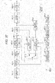
- Fig. 7 is a block diagram illustrating an exemplary main configuration of a V1 image coding device.
- Fig. 8 is a block diagram illustrating an exemplary main configuration of a V2 image coding device.
- An image coding device 100 (not illustrated) encodes a moving image including a plurality of layers such as the multi-view image illustrated in Fig. 2 .
- the image coding device 100 includes a V0 image coding device 100-0 of Fig. 6 , a V1 image coding device 100-1 of Fig. 7 , and a V2 image coding device 100-3 of Fig. 8 in order to encode views of a multi-view image.
- the V0 image coding device 100-0 encodes an image of a view 0.
- the V1 image coding device 100-1 encodes an image of a view 1.
- the V2 image coding device 100-2 encodes an image of a view 2.
- the V0 image coding device 100-0 includes an A/D converting unit 101-0, a screen sorting buffer 102-0, an operation unit 103-0, an orthogonal transforming unit 104-0, a quantizing unit 105-0, a lossless encoding unit 106-0, an accumulation buffer 107-0, an inverse quantizing unit 108-0, and an inverse orthogonal transforming unit 109-0 as illustrated in Fig. 6 .
- the V0 image coding device 100-0 further includes an operation unit 110-0, a loop filter 111-0, a decoded picture buffer 112-0, an intra predicting unit 113-0, a motion predicting/compensating unit 114-0, a prediction image selecting unit 115-0, and a rate control unit 116-0.
- the V1 image coding device 100-1 includes an A/D converting unit 101-1, a screen sorting buffer 102-1, an operation unit 103-1, an orthogonal transforming unit 104-1, a quantizing unit 105-1, a lossless encoding unit 106-1, an accumulation buffer 107-1, an inverse quantizing unit 108-1, and an inverse orthogonal transforming unit 109-1 as illustrated in Fig. 7 .
- the V1 image coding device 100-1 further includes an operation unit 110-1, a loop filter 111-1, a decoded picture buffer 112-1, an intra predicting unit 113-1, a motion predicting/compensating unit 114-1, a prediction image selecting unit 115-1, and a rate control unit 116-1.
- the V2 image coding device 100-2 includes an A/D converting unit 101-2, a screen sorting buffer 102-2, an operation unit 103-2, an orthogonal transforming unit 104-2, a quantizing unit 105-2, a lossless encoding unit 106-2, an accumulation buffer 107-2, an inverse quantizing unit 108-2, and an inverse orthogonal transforming unit 109-2 as illustrated in Fig. 8 .
- the V2 image coding device 100-2 further includes an operation unit 110-2, a loop filter 111-2, a decoded picture buffer 112-2, an intra predicting unit 113-2, a motion predicting/compensating unit 114-2, a prediction image selecting unit 115-2, and a rate control unit 116-2.
- A/D converting units 101-0 to 101-2 need not be distinguished from one another, they are referred to simply as an "A/D converting unit 101.”
- screen sorting buffers 102-0 to 102-2 need not be distinguished from one another, they are referred to simply as a "screen sorting buffer 102.”
- operation unit 103 when the operation units 103-0 to 103-2 need not be distinguished from one another, they are referred to simply as an "operation unit 103.”
- orthogonal transforming units 104-0 to 104-2 need not be distinguished from one another, they are referred to simply as an "orthogonal transforming unit 104.”
- quantizing units 105-0 to 105-2 need not be distinguished from one another, they are referred to simply as a "quantizing unit 105.”
- lossless encoding units 106-0 to 106-2 need not be distinguished from one another, they are referred to simply as a "lossless encoding unit 106.”
- the accumulation buffers 107-0 to 107-2 need not be distinguished
- operation units 110-0 to 110-2 need not be distinguished from one another, they are referred to simply as an "operation unit 110."
- loop filters 111-0 to 111-2 need not be distinguished from one another, they are referred to simply as a "loop filter 111.”
- decoded picture buffers 112-0 to 112-2 need not be distinguished from one another, they are referred to simply as a "decoded picture buffer 112.”
- intra predicting units 113-0 to 113-2 need not be distinguished from one another, they are referred to simply as an "intra predicting unit 113.”
- motion predicting/compensating units 114-0 to 114-2 need not be distinguished from one another, they are referred to simply as a "motion predicting/compensating unit 114.”
- prediction image selecting units 115-0 to 115-2 need not be distinguished from one another, they are referred to simply as a "prediction image selecting unit 115.”
- rate control units 116-0 to 116-2 need not be distinguished from one another, they are referred to simply as a "prediction image selecting unit 115.”
- the V0 image coding device 100-0 further includes a V0 motion vector compressing unit 121-0 and a V0 motion vector memory 122-0.
- the V1 image coding device 100-1 further includes a V1 motion vector compressing unit 121-1 and a V1 motion vector memory 122-1.
- the V2 image coding device 100-2 further includes a V2 motion vector compressing unit 121-2 and a V2 motion vector memory 122-2.
- the A/D converting unit 101 performs A/D conversion on input image data (image data of the view 0 in the case of the A/D converting unit 101-0, image data of the view 1 in the case of the A/D converting unit 101-1, and the image data of the view 2 in the case of the A/D converting unit 101-2), and supplies converted image data (digital data) to be stored in the screen sorting buffer 102.
- the screen sorting buffer 102 performs sorting on a stored image of frames arranged in a display order in a frame order for encoding according to a group of picture (GOP). In other words, the screen sorting buffer 102 sorts pictures arranged in a POC order in a processing order.
- the screen sorting buffer 102 supplies the image in which a frame order is sorted to the operation unit 103.
- the screen sorting buffer 102 also supplies the image in which a frame order is sorted to the intra predicting unit 113 and the motion predicting/compensating unit 114.
- the operation unit 103 subtracts a prediction image supplied from the intra predicting unit 113 or the motion predicting/compensating unit 114 via the prediction image selecting unit 115 from an image read from the screen sorting buffer 102, and outputs differential information thereof to the orthogonal transforming unit 104. For example, in the case of an image on which intra coding is performed, the operation unit 103 subtracts a prediction image supplied from the intra predicting unit 113 from an image read from the screen sorting buffer 102. Further, for example, in the case of an image on which inter coding is performed, the operation unit 103 subtracts a prediction image supplied from the motion predicting/compensating unit 114 from an image read from the screen sorting buffer 102.
- the orthogonal transforming unit 104 performs orthogonal transform such as discrete cosine transform or Karhunen Loeve transform on the differential information supplied from the operation unit 103.
- the orthogonal transforming unit 104 supplies transform coefficients to the quantizing unit 105.
- the quantizing unit 105 quantizes the transform coefficients supplied from the orthogonal transforming unit 104.
- the quantizing unit 105 sets a quantization parameter based on information related to a target value of a coding amount supplied from the rate control unit 116, and performs the quantization.
- the quantizing unit 105 supplies the quantized transform coefficients to the lossless encoding unit 106.
- the lossless encoding unit 106 encodes the transform coefficients quantized by the quantizing unit 105 according to an arbitrary coding scheme. Since coefficient data is quantized under control of the rate control unit 116, the coding amount becomes the target value set by the rate control unit 116 (or approximates to the target value).
- the lossless encoding unit 106 acquires, for example, information indicating an intra (intra-screen) prediction mode from the intra predicting unit 113, and acquires, for example, information indicating an inter (inter-screen) prediction mode and differential motion vector information from the motion predicting/compensating unit 114.
- the lossless encoding unit 106 encodes various kinds of information according to an arbitrary coding scheme, and sets (multiplexes) them as part of header information of encoded data (which is also referred to as an "encoded stream").
- the lossless encoding unit 106 supplies the encoded data obtained by the encoding to be accumulated in the accumulation buffer 107.
- Examples of the coding scheme of the lossless encoding unit 106 include variable length coding or arithmetic coding.
- variable length coding for example, there is context-adaptive variable length coding (CAVLC) defined in the H.264/AVC scheme.
- arithmetic coding for example, there is context-adaptive binary arithmetic coding (CABAC).
- the accumulation buffer 107 temporarily holds the encoded data supplied from the lossless encoding unit 106.
- the accumulation buffer 107 outputs the held encoded data to, for example, a recording device (not illustrated) (a recording medium) at a subsequent stage or a transmission path at a certain timing.
- the accumulation buffer 107 also serves as a transmitting unit that transmits the encoded data.
- the transform coefficients quantized by the quantizing unit 105 are also supplied to the inverse quantizing unit 108.
- the inverse quantizing unit 108 inversely quantizes the quantized transform coefficients by a method corresponding to the quantization performed by the quantizing unit 105.
- the inverse quantizing unit 108 supplies the obtained transform coefficients to the inverse orthogonal transforming unit 109.
- the inverse orthogonal transforming unit 109 performs inverse orthogonal transform on the transform coefficients supplied from the inverse quantizing unit 108 by a method corresponding to the orthogonal transform process performed by the orthogonal transforming unit 104.
- An output (restored differential information) that has been subjected to the inverse orthogonal transform is supplied to the operation unit 110.
- the operation unit 110 obtains a locally decoded image (decoded image) by adding the prediction image received from the intra predicting unit 113 or the motion predicting/compensating unit 114 via the prediction image selecting unit 115 to the restored differential information that is the inverse orthogonal transform result supplied from the inverse orthogonal transforming unit 109.
- the decoded image is supplied to the loop filter 111.
- the loop filter 111 includes a deblock filter, an adaptive loop filter, or the like, and performs an appropriate filter process on the decoded image supplied from the operation unit 110. For example, the loop filter 111 performs the deblock filter process on the decoded image, and removes block distortion of the decoded image. Further, for example, the loop filter 111 performs the loop filter process on the deblock filter process result (the decoded image from which the block distortion has been removed) using the Wiener Filter, and improves the image quality.
- the loop filter 111 may performs an arbitrary filter process on the decoded image.
- the loop filter 111 may supply information used in the filter process such as a filter coefficient to the lossless encoding unit 106 as necessary so that the information is encoded.
- the loop filter 111 supplies the filter process result (hereinafter, referred to as a "decoded image") to the decoded picture buffer 112.
- the loop filter 111 supplies the reconstructed image supplied from the operation unit 110 to the intra predicting unit 113.
- the decoded picture buffer 112 stores the decoded image supplied from the loop filter 111. Further, the decoded picture buffer 112 stores a view ID and a POC of the image.
- the decoded picture buffer 112 supplies the stored decoded image (and the view ID and the POC of the image) to the motion predicting/compensating unit 114 for a corresponding view at a certain timing or based on a request given from the outside such as the motion predicting/compensating unit 114.
- the decoded picture buffer 112 also supplies the stored decoded image (and the view ID and the POC of the image) to the motion predicting/compensating unit 114 for a next processed view at a certain timing or based on a request given from the outside such as the motion predicting/compensating unit 114.
- the decoded picture buffer 112-0 supplies the decoded image to the motion predicting/compensating unit 114-0 and the motion predicting/compensating unit 114-1.
- the decoded picture buffer 112-1 supplies the decoded image to the motion predicting/compensating unit 114-1 and the motion predicting/compensating unit 114-2.
- the decoded picture buffer 112-2 supplies the decoded image to the motion predicting/compensating unit 114-2.
- the intra predicting unit 113 Upon acquisition of an image of a neighboring area (a neighboring block) positioned around a processing target area (a current block) from the loop filter 111, the intra predicting unit 113 performs intra prediction of generating a prediction image basically using a prediction unit (PU) as a processing unit using pixel values of the image of the neighboring block.
- the intra predicting unit 113 performs the intra prediction in a plurality of modes (intra prediction modes) that are prepared in advance.
- the intra predicting unit 113 generates prediction images in all intra prediction modes serving as the candidate, evaluates cost function values of the prediction images using the input image supplied from the screen sorting buffer 102, and selects an optimal mode. When the optimal intra prediction mode is selected, the intra predicting unit 113 supplies the prediction image generated in the optimal mode to the prediction image selecting unit 115.
- the intra predicting unit 113 appropriately supplies intra prediction information including information related to intra prediction such as an optimal intra prediction mode to the lossless encoding unit 106 so that the intra prediction information is encoded.
- the motion predicting/compensating unit 114 performs motion prediction on a current block to generate a motion vector, and performs a compensation process according to the generated motion vector to generate a prediction image (inter prediction image information) of the current block.
- the motion predicting/compensating unit 114 generates a prediction image in all inter prediction modes serving as a candidate, evaluates a cost function value of each prediction image, and selects an optimal mode.
- the motion predicting/compensating unit 114 supplies the prediction image generated in the optimal mode to the prediction image selecting unit 115.
- the motion predicting/compensating unit 114 performs the above motion prediction and compensation processes using the decoded image acquired from the decoded picture buffer 112.
- the motion predicting/compensating unit 114 performs the motion prediction and compensation processes using the decoded image acquired from the decoded picture buffer 112 storing an image of a corresponding view.
- the motion predicting/compensating unit 114-0 performs the motion prediction and compensation processes using the decoded image acquired from the decoded picture buffer 112-0.
- the motion predicting/compensating unit 114 performs the motion prediction and compensation processes using the decoded images that are acquired from the decoded picture buffer 112 storing an image of a corresponding view and the decoded picture buffer 112 storing an image of an immediately previously processed view.
- the motion predicting/compensating unit 114-1 performs the motion prediction and compensation processes using the decoded images acquired from the decoded picture buffer 112-0 and the decoded picture buffer 112-1.
- the motion predicting/compensating unit 114-2 performs the motion prediction and compensation processes using the decoded images acquired from the decoded picture buffer 112-1 and the decoded picture buffer 112-2.
- the motion predicting/compensating unit 114 supplies inter prediction information including information related to inter prediction such as an optimal inter prediction mode to the lossless encoding unit 106 so that the inter prediction information is transmitted.
- the motion predicting/compensating unit 114 transmits a motion vector of an optimal mode as the inter prediction information so that the motion compensation is performed at the decoding side.
- the motion predicting/compensating unit 114 transmits a differential motion vector serving as a difference between a motion vector and a prediction motion vector instead of a motion vector in order to further improve the coding efficiency.
- the motion predicting/compensating unit 114 predicts a motion vector of a current block, generates a prediction motion vector, and generates a differential motion vector serving as a difference between the motion vector of the current block and the prediction motion vector.
- the motion predicting/compensating unit 114 transmits the differential motion vector to the decoding side as part of the inter prediction information.
- the motion predicting/compensating unit 114 In the prediction of the motion vector, the motion predicting/compensating unit 114 generates a prediction motion vector of a current block using a motion vector of a block neighboring a current block. At this time, in order to further improve the prediction accuracy of the prediction motion vector and to further improve the coding efficiency, the motion predicting/compensating unit 114 can generate a plurality of prediction motion vector candidates, obtain the cost function values for the respective candidates, and select an optimal candidate from among the candidates based on the cost function values. In other words, the motion predicting/compensating unit 114 can generate the prediction motion vector candidates by a plurality of methods.
- the motion predicting/compensating unit 114 can generate a prediction motion vector of a current block with reference to a motion vector of a block neighboring a current block spatially, temporally, and in terms of a view. Further, the motion predicting/compensating unit 114 transmits information (that is, mode information of a prediction motion vector) indicating a candidate selected as a prediction motion vector to the decoding side as part of the inter prediction information.
- information that is, mode information of a prediction motion vector
- the motion predicting/compensating unit 114 acquires a motion vector of a spatially neighboring block from a motion vector memory corresponding to a corresponding view.
- the motion predicting/compensating unit 114-0 acquires a motion vector from the V0 motion vector memory 122-0.
- the motion predicting/compensating unit 114-1 acquires a motion vector from the V1 motion vector memory 122-1.
- the motion predicting/compensating unit 114-2 acquires a motion vector from the V2 motion vector memory 122-2.
- the motion predicting/compensating unit 114 also acquires a motion vector of a block neighboring in terms of a view from a motion vector memory corresponding to a previously processed view.
- the motion predicting/compensating unit 114-1 acquires a motion vector from the V0 motion vector memory 122-0.
- the motion predicting/compensating unit 114-2 acquires a motion vector from the V1 motion vector memory 122-1.
- the motion vector is compressed.
- motion prediction and compensation for encoding of a current layer is performed using a motion vector that is generated and compressed in motion prediction and compensation for encoding of another layer.
- the motion predicting/compensating unit 114-0 supplies a motion vector of a current block (a motion vector of an optimal mode) generated in the motion prediction and compensation processes to the V0 motion vector compressing unit 121-0. Further, the motion predicting/compensating unit 114-1 supplies the generated motion vector of the current block to the V1 motion vector compressing unit 121-1. Furthermore, the motion predicting/compensating unit 114-2 supplies the generated motion vector of the current block to the V2 motion vector compressing unit 121-2.
- the prediction image selecting unit 115 selects a supply source of a prediction image to be supplied to the operation unit 103 and the operation unit 110. For example, in the case of the intra coding, the prediction image selecting unit 115 selects the intra predicting unit 113 as the supply source of the prediction image, and supplies the prediction image supplied from the intra predicting unit 113 to the operation unit 103 and the operation unit 110. Further, for example, in the case of the inter coding, the prediction image selecting unit 115 selects the motion predicting/compensating unit 114 as the supply source of the prediction image, and supplies the prediction image supplied from the motion predicting/compensating unit 114 to the operation unit 103 and the operation unit 110.
- the rate control unit 116 controls a rate of a quantization operation of the quantizing unit 105 based on the coding amount of the encoded data accumulated in the accumulation buffer 107 such that neither an overflow nor an underflow occurs.
- the V0 motion vector compressing unit 121-0 performs compression (which is also referred as "1/16 compression”) on a motion vector of a maximum of 4 ⁇ 4 accuracy (which is also referred to as a "non-compressed V0 motion vector") acquired from the motion predicting/compensating unit 114-0 with the 16 ⁇ 16 accuracy, and supplies the compressed motion vector (which is also referred to as a "1/16-compressed V0 motion vector") to the V0 motion vector memory 122-0.
- a method of compressing a motion vector is arbitrary.
- the V0 motion vector compressing unit 121-0 may select a motion vector serving as a representative value from among a plurality of motion vectors acquired from the motion predicting/compensating unit 114-0.
- one motion vector serving as a representative value may be selected from among 16 motion vectors (motion vectors of 4 ⁇ 4 blocks) of the 4 ⁇ 4 accuracy. Through this compression, the accuracy of the motion vector becomes the 16 ⁇ 16 accuracy.
- a method of selecting the motion vector is arbitrary.
- a motion vector of a block at a position determined by a certain method may be selected, and for example, a motion vector of a block at a certain position such as a block at an upper left end may be selected, and a block corresponding to a position in an image may be selected.
- the number of selected motion vectors is arbitrary and may be 2 or more.
- the V0 motion vector compressing unit 121-0 calculates a representative value through a certain operation using each motion vector.
- a method of calculating a representative value is arbitrary. For example, an average value or a median value of motion vectors of respective blocks may be used as a representative value. Further, the number of calculated representative values is arbitrary and may be 2 or more.
- the 1/16-compressed V0 motion vector (the representative value of the motion vector) obtained as described above is supplied to and stored in the V0 motion vector memory 122-0.
- the V0 motion vector memory 122-0 appropriately supplies the stored 1/16-compressed V0 motion vector to the motion predicting/compensating unit 114-0 as a motion vector of a temporally neighboring block. Further, the V0 motion vector memory 122-0 appropriately supplies the stored 1/16-compressed V0 motion vector to the motion predicting/compensating unit 114-1 as a motion vector of a block neighboring in terms of a view.
- the V1 motion vector compressing unit 121-1 performs 1/16 compression on a motion vector of a maximum of 4 ⁇ 4 accuracy (which is also referred to as a "non-compressed V1 motion vector") acquired from the motion predicting/compensating unit 114-1, and supplies the compressed motion vector (which is also referred to as a "1/16-compressed V1 motion vector") to be stored in the V1 motion vector memory 122-1.
- the V1 motion vector memory 122-1 appropriately supplies the stored 1/16-compressed V1 motion vector to the motion predicting/compensating unit 114-1 as a motion vector of a temporally neighboring block. Further, the V1 motion vector memory 122-1 appropriately supplies the stored 1/16-compressed V1 motion vector to the motion predicting/compensating unit 114-2 as a motion vector of a block neighboring in terms of a view.
- the V2 motion vector compressing unit 121-2 performs 1/16 compression on a motion vector of a maximum of 4 ⁇ 4 accuracy (which is also referred to as a "non-compressed V2 motion vector") acquired from the motion predicting/compensating unit 114-2, and supplies the compressed motion vector (which is also referred to as a "1/16-compressed V2 motion vector") to be stored in the V2 motion vector memory 122-2.
- the V2 motion vector memory 122-2 appropriately supplies the stored 1/16-compressed V2 motion vector to the motion predicting/compensating unit 114-2 as a motion vector of a temporally neighboring block.
- a method of compressing a motion vector through the V1 motion vector compressing unit 121-1 and the V2 motion vector compressing unit 121-2 is the same as in the V0 motion vector compressing unit 121-0, and thus a description thereof is omitted.
- the V0 motion vector compressing unit 121-0, the V1 motion vector compressing unit 121-1, and the V2 motion vector compressing unit 121-2 perform the above motion vector compression in certain units.
- the V0 motion vector compressing unit 121-0, the V1 motion vector compressing unit 121-1, and the V2 motion vector compressing unit 121-2 may perform the above motion vector compression in units of LCUs.
- the V0 motion vector compressing unit 121-0, the V1 motion vector compressing unit 121-1, and the V2 motion vector compressing unit 121-2 may be the same or differ in the processing unit. The processing unit may be changed during a sequence.
- the motion vector compression methods performed by the V0 motion vector compressing unit 121-0, the V1 motion vector compressing unit 121-1, and the V2 motion vector compressing unit 121-2 may be the same as or different from one another.
- the V0 motion vector compressing unit 121-0, the V1 motion vector compressing unit 121-1, and the V2 motion vector compressing unit 121-2 can reduce (that is, compress) an information amount of motion vectors by reducing the number of motion vectors.
- the motion predicting/compensating unit 114 may refer to the motion vectors stored in the V0 motion vector memory 122-0, the V1 motion vector memory 122-1, and the V2 motion vector memory 122-2 as the motion vector for the IVMP as well as the motion vector for the TMVP.
- the motion vector for the TMVP and the motion vector for the IVMP are commonalized as described above, it is possible to reduce the storage capacity necessary for encoding. Further, it is possible to suppress an increase in a load caused by compression of a motion vector. Accordingly, it is possible to implement a reduction in a manufacturing or developing cost, device downsizing, a reduction in power consumption, and the like for the image coding device 100.
- step S1001 the V0 image coding device 100-0 performs a V0 coding process on a current picture.
- step S1002 the V1 image coding device 100-1 performs a V1 coding process on the current picture.
- step S1003 the V2 image coding device 100-2 performs a V2 coding process on the current picture.
- step S1004 the image coding device 100 determines whether or not all pictures have been processed, and when it is determined that there is a non-processed picture, the process returns to step S1001, and the subsequent process is repeated.
- steps S1001 to S1004 is repeatedly performed for each picture, and when it is determined in step S1004 that all pictures have been processed, the image coding device 100 ends the coding process.
- step S1101 the A/D converting unit 101-0 performs A/D conversion on an input image.
- step S1102 the screen sorting buffer 102-0 stores the A/D converted image, and sorts respective pictures arranged in a display order in an encoding order.
- step S1103, the intra predicting unit 113-0 performs the intra prediction process of the intra prediction mode.
- step S1104 the motion predicting/compensating unit 114-0 performs a V0 inter motion prediction process in which the motion prediction and the motion compensation of the inter prediction mode are performed.
- step S1105 the prediction image selecting unit 115-0 selects either of the prediction image generated by the intra predicting unit 113-0 and the prediction image generated by the motion predicting/compensating unit 114-0.
- the V0 motion vector compressing unit 121-0 performs compression (1/16 compression) on a non-compressed V0 motion vector of a maximum of 4 ⁇ 4 accuracy that is a motion vector of a current picture of the view 0 generated by the process of step S1104 with the 16 ⁇ 16 accuracy.
- the 1/16 compression is performed in units of LCUs (for example, 16 ⁇ 16 pixels) .
- the V0 motion vector compressing unit 121-0 selects a V0 motion vector of a block of 16 ⁇ 16 pixels at an upper left end as a representative value (that is, a V0 motion vector of the 16 ⁇ 16 accuracy) of the 16 ⁇ 16 pixels.
- step S1107 the V0 motion vector memory 122-0 stores the 1/16-compressed V0 motion vector generated by the process of step S1106.
- step S1108 the operation unit 103-0 subtracts the prediction image selected by the process of step S1105 from the image sorted by the process of step S1102. Differential data (data of a differential image between the image sorted by the process of step S1102 and the prediction image selected in step S1105) obtained by this operation is reduced to be smaller in a data amount than original image data. Thus, it is possible to reduce a data amount compared to when an image is encoded without change.
- step S1109 the orthogonal transforming unit 104-0 performs the orthogonal transform process on the differential data generated by the process of step S1108.
- step S1110 the quantizing unit 105-0 quantizes the orthogonal transform coefficients obtained by the process of step S1109 using the quantization parameter calculated by the rate control unit 116-0.
- step S1111 the lossless encoding unit 106-0 encodes the coefficients quantized by the process of step S1110.
- lossless coding such as variable length coding or arithmetic coding is performed on data corresponding to a differential image.
- the lossless encoding unit 106-0 encodes information related to the prediction mode of the prediction image selected by the process of step S1105, and adds the encoded information to the encoded data obtained by encoding the differential image.
- the lossless encoding unit 106-0 also encodes the optimal intra prediction mode information supplied from the intra predicting unit 113-0, information according to the optimal inter prediction mode supplied from the motion predicting/compensating unit 114-0, or the like, and adds the encoded information to the encoded data.
- step S1112 the accumulation buffer 107-0 accumulates the encoded data obtained by the process of step S1111.
- the encoded data accumulated in the accumulation buffer 107-0 is appropriately read, and transmitted to the decoding side via a transmission path or a recording medium.
- step S1113 the inverse quantizing unit 108-0 inversely quantizes the orthogonal transform coefficients (which are also referred to as "quantization coefficients") generated and quantized by the process of step S1110 according to characteristics corresponding to characteristics of the quantizing unit 105-0.
- step S1114 the inverse orthogonal transforming unit 109-0 performs inverse orthogonal transform on the orthogonal transform coefficients obtained by the process of step S1113 according to characteristics corresponding to characteristics of the orthogonal transforming unit 104-0. As a result, a differential image is restored.
- step S1115 the operation unit 110-0 adds the prediction image selected in step S1105 to the differential image restored in step S1114, and generates a locally decoded image (reconstructed image).
- the V0 image coding device 100-0 performs the process of steps S1103 to S1115 on blocks in a current LCU serving as a processing target.
- step S1116 the V0 image coding device 100-0 determines whether or not all LCUs have been processed. When it is determined that there is a non-processed LCU, the process returns to step S1103, and the subsequent process is repeated.
- the process of steps S1103 to S1115 is performed on each LCU of an image of a view 0 of a current picture, and when it is determined in step S1116 that all LCUs have been processed, the process proceeds to step S1117.
- step S1117 the loop filter 111-0 appropriately performs the loop filter process such as the deblock filter process or the adaptive loop filter process on the reconstructed image obtained by the process of step S1115, and generates the decoded image.
- the loop filter process such as the deblock filter process or the adaptive loop filter process
- step S1118 the decoded picture buffer 112-0 stores the decoded image generated by the process of step S1117.
- step S1119 the rate control unit 116-0 control the rate of the quantization operation of the quantizing unit 105-0 based on the coding amount (the generated coding amount) of the encoded data accumulated in the accumulation buffer 107-0 by the process of step S1118 such that neither an overflow nor an underflow occurs. Further, the rate control unit 116-0 supplies information related to the quantization parameter to the quantizing unit 105-0.
- step S1119 ends, the V0 coding process ends, and the process returns to Fig. 9 .
- step S1131 the motion predicting/compensating unit 114-0 performs the motion search process, and generates a motion vector of a current block.
- the motion predicting/compensating unit 114-0 decides a spatial prediction motion vector candidate using a non-compressed V0 motion vector in a picture.
- the spatial prediction motion vector candidate refers to a prediction motion vector candidate generated from a motion vector of a block spatially neighboring a current block.
- the motion predicting/compensating unit 114-0 decides the spatial prediction motion vector candidate using a V0 motion vector of a block spatially neighboring a current block.
- the V0 motion vector is a motion vector in a current picture and thus held in a non-compressed (a maximum of 4 ⁇ 4 accuracy) state by the motion predicting/compensating unit 114-0.
- the motion predicting/compensating unit 114-0 decides the spatial prediction motion vector candidate using the non-compressed V0 motion vector.
- the motion predicting/compensating unit 114-0 decides the temporal prediction motion vector candidate using a 1/16-compressed V0 motion vector of another picture.
- the temporal prediction motion vector candidate refers to a prediction motion vector candidate generated from a motion vector of a block temporally neighboring a current block.
- the motion predicting/compensating unit 114-0 decides the spatial prediction motion vector candidate using a V0 motion vector of a colocated block of a picture temporally neighboring a current block.
- the V0 motion vector is a motion vector of a different picture of the same view as a current picture and thus held in the V0 motion vector memory 122-0 in a compressed (the 16 ⁇ 16 accuracy) state.
- the motion predicting/compensating unit 114-0 reads the 1/16-compressed V0 motion vector from the V0 motion vector memory 122-0, and decides the temporal prediction motion vector candidate using the 1/16-compressed V0 motion vector.
- step S1134 the motion predicting/compensating unit 114-0 calculates cost function values for the candidates generated in steps S1132 and S1133.
- step S1135 the motion predicting/compensating unit 114-0 determines an optimal prediction mode based on the cost function values calculated in step S1134. At this time, the motion predicting/compensating unit 114-0 also decides (a mode of) a prediction motion vector.
- step S1136 the motion predicting/compensating unit 114-0 performs motion compensation in the optimal mode determined in step S1135, and generates a prediction image. Further, the motion predicting/compensating unit 114-0 generates the inter prediction information including the optimal inter prediction mode, the differential motion vector, and the mode of the prediction motion vector.
- step S1137 the motion predicting/compensating unit 114-0 stores the motion vector of the optimal mode in a buffer as the non-compressed V0 motion vector.
- the V0 inter motion prediction process ends, and the process returns to Fig. 10 .
- the V1 image coding device 100-1 performs the V1 coding process basically in the same manner as the coding process (the V0 coding process of Fig. 10 ) for the view 0.
- the process of steps S1201 to S1219 of Fig. 12 is performed basically in the same manner as the process of steps S1101 to S1119 of Fig. 10 .
- the description of Fig. 12 may proceed such that the respective components of the V0 image coding device 100-0 described with reference to Fig. 10 are replaced with the respective components of the V1 image coding device 100-1, and the process for the view 0 illustrated in Fig. 10 is replaced with the process for the view 1, and thus a description thereof is omitted.
- the process of steps S1231 to S1233 is performed basically in the same manner as the process of steps S1131 to S1133 of Fig. 11 .
- the V1 inter motion prediction process is performed by the motion predicting/compensating unit 114-1.
- the process of Fig. 13 is performed on the view 1, and thus in step S1232, a non-compressed V1 motion vector serving as a non-compressed motion vector of the view 1 is used. Further, in step S1233, a 1/16-compressed V1 motion vector that has been subjected to 1/16 compression is used.
- the motion predicting/compensating unit 114-1 decides an IVMP prediction motion vector candidate using a 1/16-compressed V0 motion vector.
- the IVMP prediction motion vector candidate refers to a prediction motion vector candidate generated from a motion vector of a block neighboring a current block in terms of a view.
- the motion predicting/compensating unit 114-1 decides the IVMP prediction motion vector candidate using a V0 motion vector of a colocated block of an image of a different view of the same picture as a current block.
- the V0 motion vector is a motion vector of a different view of the same picture as a current picture and thus held in the V0 motion vector memory 122-0 in a compressed (the 16 ⁇ 16 accuracy) state.
- the motion predicting/compensating unit 114-1 reads the 1/16-compressed V0 motion vector from the V0 motion vector memory 122-0, and decides an inter-view prediction motion vector candidate using the 1/16-compressed V0 motion vector.
- steps S1235 to step S1238 is performed, similarly to the process of step S1134 to step S1137 of Fig. 11 .
- the V1 inter motion prediction process ends, and the process returns to Fig. 12 .
- the process for the view 2 is performed, similarly to the process for the view 1.
- the V2 image coding device 100-2 performs the V2 coding process basically in the same manner as the coding process (the V1 coding process of Fig. 12 ) for the view 1.
- the process of step S1301 to step S1319 of Fig. 14 is performed basically in the same manner as the process of step S1201 to step S1219 of Fig. 12 .
- the description of Fig. 14 may proceed such that the respective components of the V1 image coding device 100-1 described with reference to Fig. 12 are replaced with the respective components of the V2 image coding device 100-2, and the process for the view 1 illustrated in Fig. 12 is replaced with the process for the view 2, and thus a description thereof is omitted.
- the motion predicting/compensating unit 114-2 performs the V2 inter motion prediction process basically in the same manner as the inter motion prediction process (the V1 inter motion prediction process of Fig. 13 ) for the view 1 as illustrated in Fig. 15 .
- the process of step S1331 to step S1338 of Fig. 15 is performed basically in the same manner as step S1231 to step S1238 of Fig. 13 .
- step S1332 a non-compressed V2 motion vector serving as a non-compressed motion vector of the view 2 is used. Further, in step S1333, a 1/16-compressed V2 motion vector that has been subjected to 1/16 compression is used. Further, in step S1334, a 1/16-compressed V1 motion vector that has been subjected to 1/16 compression is used.
- step S1338 ends, the V2 inter motion prediction process ends, and the process returns to Fig. 14 .
- the image coding device 100 can reduce the memory capacity necessary for the motion vector for the IVMP, and suppress an increase in the storage capacity necessary for encoding and decoding.
- Fig. 16 is a block diagram illustrating an exemplary main configuration of the V0 image decoding device .
- Fig. 17 is a block diagram illustrating an exemplary main configuration the V1 image decoding device.
- Fig. 18 is a block diagram illustrating an exemplary main configuration the V2 image decoding device.
- An image decoding device 200 decodes encoded data of a moving image including a plurality of layers such as the multi-view image illustrated in Fig. 2 which is encoded by the image coding device 100 by a decoding method corresponding to the encoding method.
- the image decoding device 200 includes a V0 image decoding device 200-0 of Fig. 16 , a V1 image decoding device 200-1 of Fig. 17 , and a V2 image decoding device 200-2 of Fig. 18 in order to decode encoded data of respective views of a multi-view image.
- the V0 image decoding device 200-0 decodes encoded data of an image of a view 0 encoded by the V0 image coding device 100-0.
- the V1 image decoding device 200-1 decodes encoded data of an image of a view 1 encoded by the V1 image coding device 100-1.
- the V2 image decoding device 200-2 decodes encoded data of an image of a view 2 encoded by the V2 image coding device 100-2.
- the V0 image decoding device 200-0 includes an accumulation buffer 201-0, a lossless decoding unit 202-0, an inverse quantizing unit 203-0, an inverse orthogonal transforming unit 204-0, an operation unit 205-0, a loop filter 206-0, a screen sorting buffer 207-0, and a D/A converting unit 208-0 as illustrated in Fig. 16 .
- the V0 image decoding device 200-0 further includes a decoded picture buffer 209-0, an intra predicting unit 210-0, a motion compensating unit 211-0, and a selecting unit 212-0.
- the V1 image decoding device 200-1 includes an accumulation buffer 201-1, a lossless decoding unit 202-1, an inverse quantizing unit 203-1, an inverse orthogonal transforming unit 204-1, an operation unit 205-1, a loop filter 206-1, a screen sorting buffer 207-1, and a D/A converting unit 208-1 as illustrated in Fig. 17 .
- the V1 image decoding device 200-1 further includes a decoded picture buffer 209-1, an intra predicting unit 210-1, a motion compensating unit 211-1, and a selecting unit 212-1.
- the V2 image decoding device 200-2 includes an accumulation buffer 201-2, a lossless decoding unit 202-2, an inverse quantizing unit 203-2, an inverse orthogonal transforming unit 204-2, an operation unit 205-2, a loop filter 206-2, a screen sorting buffer 207-2, and a D/A converting unit 208-2 as illustrated in Fig. 18 .
- the V2 image decoding device 200-2 further includes a decoded picture buffer 209-2, an intra predicting unit 210-2, a motion compensating unit 211-2, and a selecting unit 212-2.
- accumulation buffers 201-0 to 201-2 need not be distinguished from one another, they are referred to simply as an "accumulation buffer 201.”
- lossless decoding units 202-0 to 202-2 need not be distinguished from one another, they are referred to simply as a “lossless decoding unit 202.”
- inverse quantizing units 203-0 to 203-2 need not be distinguished from one another, they are referred to simply as an "inverse quantizing unit 203.”
- inverse orthogonal transforming units 204-0 to 204-2 need not be distinguished from one another, they are referred to simply as an "inverse orthogonal transforming unit 204.”
- operation unit 205-0 to 205-2 need not be distinguished from one another, they are referred to simply as an "operation unit 205.”
- loop filters 206-0 to 206-2 need not be distinguished from one another, they are referred to simply as a "loop filter 206.”
- screen sorting buffers 207-0 to 207-2 need not be distinguished from one another, they are referred to simply as a "screen sorting buffer 207.”
- D/A converting units 208-0 to 208-2 need not be distinguished from one another, they are referred to simply as a "D/A converting unit 208.”
- decoded picture buffers 209-0 to 209-2 need not be distinguished from one another, they are referred to simply as a "decoded picture buffer 209."
- intra predicting units 210-0 to 210-2 need not be distinguished from one another, they are referred to simply as an "intra predicting unit 210.”
- motion compensating units 211-0 to 211-2 need not be distinguished from one another, they are referred to simply as a “motion compensating unit 211.”
- selecting units 212-0 to 212-2 need not be distinguished from one another, they are referred to simply as a “selecting unit 212.”
- the V0 image decoding device 200-0 further includes a V0 motion vector compressing unit 221-0 and a V0 motion vector memory 222-0.
- the V1 image decoding device 200-1 further includes a V1 motion vector compressing unit 221-1 and a V1 motion vector memory 222-1.
- the V2 image decoding device 200-2 further includes a V2 motion vector compressing unit 221-2 and a V2 motion vector memory 222-2.
- the accumulation buffer 201 also functions as a receiving unit that receives transmitted encoded data.
- the accumulation buffer 201 receives and accumulates transmitted encoded data, and supplies the encoded data to the lossless decoding unit 202 at a certain timing.
- the encoded data includes information necessary for decoding such as prediction mode information.
- the lossless decoding unit 202 decodes information encoded by the lossless encoding unit 106 ( Figs. 6 to 8 ) which is supplied from the accumulation buffer 201 according to a scheme corresponding to the coding scheme of the lossless encoding unit 106.
- the lossless decoding unit 202 supplies quantized coefficient data of a differential image obtained by the decoding to the inverse quantizing unit 203.
- the lossless decoding unit 202 determines which of the intra prediction mode and the inter prediction mode has been selected as the optimal prediction mode, and supplies information related to the optimal prediction mode to a mode determined to be selected, that is, the intra predicting unit 210 or the motion compensating unit 211.
- the intra prediction mode is selected as the optimal prediction mode at the encoding side
- the information related to the optimal prediction mode is supplied to the intra predicting unit 210.
- the inter prediction mode is selected as the optimal prediction mode at the encoding side
- the information related to the optimal prediction mode is supplied to the motion compensating unit 211.
- the lossless decoding unit 202 supplies information necessary for inverse quantization such as a quantization matrix and a quantization parameter to the inverse quantizing unit 203.
- the inverse quantizing unit 203 inversely quantizes the quantized coefficient data that is obtained by the decoding performed by the lossless decoding unit 202 according to a scheme corresponding to the quantization scheme of the quantizing unit 105.
- the inverse quantizing unit 203 is a processing unit similar to the inverse quantizing unit 108. In other words, the description of the inverse quantizing unit 203 can also apply to the inverse quantizing unit 108.
- the inverse quantizing unit 203 supplies the obtained coefficient data to the inverse orthogonal transforming unit 204.
- the inverse orthogonal transforming unit 204 performs inverse orthogonal transform on the orthogonal transform coefficients supplied from the inverse quantizing unit 203 according to a scheme corresponding to the orthogonal transform scheme of the orthogonal transforming unit 104.
- the inverse orthogonal transforming unit 204 is a processing unit similar to the inverse orthogonal transforming unit 109. In other words, the description of the inverse orthogonal transforming unit 204 can also apply to the inverse orthogonal transforming unit 109.
- the inverse orthogonal transforming unit 204 obtains decoding residual data (differential image) corresponding to residual data (differential image) that is not subjected to orthogonal transform in the image coding device 100 through the inverse orthogonal transform process.
- the differential image obtained by the inverse orthogonal transform is supplied to the operation unit 205. Further, the operation unit 205 is supplied with a prediction image from the intra predicting unit 210 or the motion compensating unit 211 via the selecting unit 212.
- the operation unit 205 adds the differential image to the prediction image, and obtains a reconstructed image corresponding to image data from which a prediction image is not subtracted by the operation unit 103.
- the operation unit 205 supplies the reconstructed image to the loop filter 206.
- the loop filter 206 appropriately performs the loop filter process such as the deblock filter process or the adaptive loop filter process on the supplied reconstructed image, and generates the decoded image. For example, the loop filter 206 performs the deblock filter process on the reconstructed image, and removes block distortion. Further, for example, the loop filter 206 improves the image quality by performing the loop filter process on the deblock filter process result (the reconstructed image from which the block distortion has been removed) using the Wiener Filter.
- the loop filter 206 improves the image quality by performing the loop filter process on the deblock filter process result (the reconstructed image from which the block distortion has been removed) using the Wiener Filter.
- a type of the filter process performed by the loop filter 206 is arbitrary, and any other filter process may be performed. Further, the loop filter 206 may perform the filter process using a filter coefficient supplied from the image coding device 100.
- the loop filter 206 supplies the decoded image serving as the filter process result to the screen sorting buffer 207 and the decoded picture buffer 209. Further, the loop filter 206 supplies the output (reconstructed image) of the operation unit 205 to the intra predicting unit 210 without performing the filter process.
- the intra predicting unit 210 uses pixel values of pixels included in this image as pixel values of neighboring pixels.
- the screen sorting buffer 207 performs sorting on the supplied decoded image. In other words, the frames sorted in an order for encoding by the screen sorting buffer 102 are sorted in an original display order.
- the D/A converting unit 208 performs D/A conversion on the decoded image supplied from the screen sorting buffer 207, outputs the converted image to be displayed on a display (not illustrated).
- the decoded picture buffer 209 stores the supplied decoded image (and the view ID and the POC of the image) . Further, the decoded picture buffer 209 supplies the stored decoded image (and the view ID and the POC of the image) to the motion compensating unit 211 at a certain timing or based on a request given from the outside such as the motion compensating unit 211.
- the intra predicting unit 210 performs basically the same process as the intra predicting unit 113.
- the intra predicting unit 210 performs intra prediction only on an area in which a prediction image is generated by intra prediction at the time of encoding.
- the intra predicting unit 210 supplies a generated prediction image to the operation unit 205 via the selecting unit 212 for each area of a prediction processing unit.
- the motion compensating unit 211 generates a prediction image by performing motion compensation on the area in which inter prediction has been performed at the time of encoding in the inter prediction mode employed at the time of encoding based on the inter prediction information supplied from the lossless decoding unit 202.
- the motion compensating unit 211 supplies the generated prediction image to the operation unit 205 via the selecting unit 212 for each area of a prediction processing unit.
- the motion compensating unit 211 performs the motion compensation process using the decoded image acquired from the decoded picture buffer 209.
- the motion compensating unit 211 performs the motion compensation process using the decoded image acquired from the decoded picture buffer 209 storing an image of a corresponding view.
- the motion compensating unit 211-0 performs the motion compensation process using the decoded image acquired from the decoded picture buffer 209-0.
- the motion compensating unit 211 performs the motion compensation process using the decoded images acquired from the decoded picture buffer 209 storing an image of a corresponding view and the decoded picture buffer 209 storing an image of an immediately previously processed view.
- the motion compensating unit 211-1 performs the motion compensation process using the decoded images acquired from the decoded picture buffer 209-0 and the decoded picture buffer 209-1.
- the motion compensating unit 211-2 performs the motion compensation process using the decoded images acquired from the decoded picture buffer 209-1 and the decoded picture buffer 209-2.
- the motion compensating unit 211 reconstructs a motion vector of a current block from a differential motion vector transmitted from the encoding side as the inter prediction information. At this time, the motion compensating unit 211 predicts the motion vector of the current block by the same method (mode) as in the motion predicting/compensating unit 114 based on the inter prediction information supplied from the lossless decoding unit 202, and generates a prediction motion vector. The motion compensating unit 211 adds the prediction motion vector to the differential motion vector, and reconstructs the motion vector of the current block.
- the motion compensating unit 211 generates the prediction motion vector of the current block with reference to a motion vector of a block neighboring the current block spatially, temporally, or in terms of a view.
- the motion vector of the spatially neighboring block is held by the motion compensating unit 211. Further, when a motion vector of a temporally neighboring block is referred to, the motion compensating unit 211 acquires a motion vector from a motion vector memory corresponding to a corresponding view. For example, the motion compensating unit 211-0 acquires a motion vector of a temporally neighboring block from the V0 motion vector memory 222-0. Further, for example, the motion compensating unit 211-1 acquires a motion vector of a temporally neighboring block from the V1 motion vector memory 222-1. Furthermore, for example, the motion compensating unit 211-2 acquires a motion vector of a temporally neighboring block from the V2 motion vector memory 222-2.
- the motion compensating unit 211 acquires a motion vector from a motion vector memory corresponding to a previously processed view.
- the motion compensating unit 211-1 acquires a motion vector of a block neighboring in terms of a view from the V0 motion vector memory 222-0.
- the motion compensating unit 211-2 acquires a motion vector of a block neighboring in terms of a view from the V1 motion vector memory 222-1.
- the motion vectors acquired from the motion vector memories are subjected to 1/16 compression.
- motion compensation for decoding of a current layer is performed using a motion vector that is reconstructed and compressed in motion compensation for decoding of another layer.
- the motion compensating unit 211 supplies the motion vector of the current block (a motion vector of an optimal mode) generated through the motion prediction and compensation processes to the V0 motion vector compressing unit 221-0. Further, the motion compensating unit 211-1 supplies the generated motion vector of the current block to the V1 motion vector compressing unit 221-1. Furthermore, the motion compensating unit 211-2 supplies the generated motion vector of the current block to the V2 motion vector compressing unit 221-2.
- the selecting unit 212 supplies the prediction image supplied from the intra predicting unit 210 or the prediction image supplied from the motion compensating unit 211 to the operation unit 205.
- the V0 motion vector compressing unit 221-0 performs 1/16 compression on the non-compressed V0 motion vector of a maximum of 4 ⁇ 4 accuracy acquired from the motion compensating unit 211-0 with the 16 ⁇ 16 accuracy, and supplies the obtained 1/16-compressed V0 motion vector to the V0 motion vector memory 222-0.
- a method of compressing a motion vector is arbitrary as long as the same method as in the V0 motion vector compressing unit 121-0 is used.
- a method of selecting a motion vector is arbitrary as long as the same method as in the V0 motion vector compressing unit 121-0 is used.
- the number of selected motion vectors is arbitrary as long as the same method as in the V0 motion vector compressing unit 121-0 is used, and may be 2 or more.
- a method of calculating a representative value is arbitrary as long as the same method as in the V0 motion vector compressing unit 121-0 is used.
- the 1/16-compressed V0 motion vector (the representative value of the motion vector) obtained as described above is supplied to and stored in the V0 motion vector memory 222-0.
- the V0 motion vector memory 222-0 appropriately supplies the stored 1/16-compressed V0 motion vector to the motion compensating unit 211-0 as a motion vector of a temporally neighboring block. Further, the V0 motion vector memory 222-0 appropriately supplies the stored 1/16-compressed V0 motion vector to the motion compensating unit 211-1 as a motion vector of a block neighboring in terms of a view.
- the V1 motion vector compressing unit 221-1 performs 1/16 compression on the non-compressed V1 motion vector acquired from the motion compensating unit 211-1, and supplies the obtained 1/16-compressed V1 motion vector to be stored in the V1 motion vector memory 222-1.
- the V1 motion vector memory 222-1 appropriately supplies the stored 1/16-compressed V1 motion vector to the motion compensating unit 211-1 as a motion vector of a temporally neighboring block. Further, the V1 motion vector memory 222-1 appropriately supplies the stored 1/16-compressed V1 motion vector to the motion compensating unit 211-2 as a motion vector of a block neighboring in terms of a view.
- the V2 motion vector compressing unit 221-2 performs 1/16 compression on the non-compressed V2 motion vector acquired from the motion compensating unit 211-2, and supplies the obtained 1/16-compressed V2 motion vector to be stored in the V2 motion vector memory 222-2.
- the V2 motion vector memory 222-2 appropriately supplies the stored 1/16-compressed V2 motion vector to the motion compensating unit 211-2 as a motion vector of a temporally neighboring block.
- a method of compressing a motion vector through the V1 motion vector compressing unit 221-1 and the V2 motion vector compressing unit 221-2 is the same as in the V0 motion vector compressing unit 221-0, and thus a description thereof is omitted.
- the V0 motion vector compressing unit 221-0, the V1 motion vector compressing unit 221-1, and the V2 motion vector compressing unit 221-2 performs the above motion vector compression in certain units.
- the V0 motion vector compressing unit 221-0, the V1 motion vector compressing unit 221-1, and the V2 motion vector compressing unit 221-2 may perform the above motion vector compression in units of LCUs.
- the V0 motion vector compressing unit 221-0, the V1 motion vector compressing unit 221-1, and the V2 motion vector compressing unit 221-2 may be the same or different in the processing unit.
- the processing unit may be changed during a sequence .
- the motion vector compression methods performed by the V0 motion vector compressing unit 221-0, the V1 motion vector compressing unit 221-1, and the V2 motion vector compressing unit 221-2 may be the same as or different from one another.
- the V0 motion vector compressing unit 221-0, the V1 motion vector compressing unit 221-1, and the V2 motion vector compressing unit 221-2 can reduce (that is, compress) an information amount of motion vectors by reducing the number of motion vectors.
- the motion compensating unit 211 may refer to the motion vectors stored in the V0 motion vector memory 222-0, the V1 motion vector memory 222-1, and the V2 motion vector memory 222-2 as the motion vector for the IVMP as well as the motion vector for the TMVP.
- the motion vector for the TMVP and the motion vector for the IVMP are commonalized as described above, it is possible to reduce the storage capacity necessary for encoding. Further, it is possible to suppress an increase in a load caused by compression of a motion vector. Accordingly, it is possible to implement a reduction in a manufacturing or developing cost, device downsizing, a reduction in power consumption, and the like for the image decoding device 200.
- the V0 image decoding device 200-0 When the decoding process starts, for a current picture, the V0 image decoding device 200-0 performs a V0 decoding process in step S1401, the V1 image decoding device 200-1 performs a V1 decoding process in step S1402, and the V2 image decoding device 200-2 performs a V2 decoding process in step S1403.
- step S1404 the image decoding device 200 determines whether or not all pictures have been processed, and when it is determined that there is a non-processed picture, the process returns to step S1401, and the subsequent process is repeated.
- step S1401 to step S1404 is repeatedly performed for each picture, and when it is determined, in step S1404, that all pictures have been processed, the image decoding device 200 ends the decoding process .
- step S1501 the accumulation buffer 201-0 accumulates transmitted bit streams of the view 0.
- step S1502 the lossless decoding unit 202-0 decodes the bit streams (encoded differential image information) of the view 0 supplied from the accumulation buffer 201-0.
- the respective pictures (an I picture, a P picture, and a B picture) of the view 0 encoded by the lossless encoding unit 106-0 are decoded.
- various kinds of pieces of information excluding the differential image information included in the bit streams such as header information are also decoded.
- step S1503 the inverse quantizing unit 203-0 inversely quantizes the quantized coefficients obtained by the process of step S1503.
- step S1504 the inverse orthogonal transforming unit 204-0 performs inverse orthogonal transform as necessary on the coefficients inversely quantized by the process of step S1503.
- step S1505 the lossless decoding unit 202-0 determines whether or not the prediction mode applied at the time of encoding is the inter prediction. When the prediction mode applied at the time of encoding is determined to be the inter prediction, the process proceeds to step S1506.
- step S1506 the motion compensating unit 211-0 performs the V0 motion compensation process, and generates a prediction image.
- step S1506 the process proceeds to step S1508.
- step S1507 the intra predicting unit 210-0 performs the intra prediction process, and generates a prediction image.
- step S1507 the process proceeds to step S1508.
- step S1508 the operation unit 205-0 adds the prediction image generated by the process of step S1506 or the process of step S1507 to the differential image information obtained through the inverse orthogonal transform performed by the process of step S1504.
- the reconstructed image is generated.
- step S1509 the V0 motion vector compressing unit 221-0 performs 1/16 compression on the non-compressed V0 motion vector generated by the process of step S1506, similarly to the V0 motion vector compressing unit 121-0.
- step S1510 the V0 motion vector memory 222-0 stores the 1/16-compressed V0 motion vector generated by the process of step S1509, similarly to the V0 motion vector memory 122-0.
- the V0 image decoding device 200-0 performs the process of step S1501 to step S1510 on each block in a current LCU serving as a processing target.
- step S1511 the V0 image decoding device 200-0 determines whether or not all LCUs have been processed. When it is determined that there is a non-processed LCU, the process returns to step S1501, and the subsequent process is repeated.
- the process of step S1501 to step S1510 is performed on each LCU of an image of a view 0 of a current picture, and when all LCUs are determined to have been processed in step S1511, the process proceeds to step S1512.
- step S1512 the loop filter 206-0 appropriately performs the loop filter process such as the deblock filter process or the adaptive loop filter process on the reconstructed image obtained in step S1508.
- step S1513 the screen sorting buffer 207-0 performs sorting on the decoded image generated by the filter process performed in step S1512.
- the frames sorted in an order for encoding by the screen sorting buffer 102-0 are sorted in an original display order.
- step S1514 the D/A converting unit 208-0 performs D/A conversion on the decoded image of the view 0 in which the order of frames is sorted.
- the decoded image is output to and displayed on a display (not illustrated) .
- step S1515 the decoded picture buffer 209-0 stores the decoded image obtained by the filter process in step S1512.
- the decoded image is used as a reference image in the inter prediction process.
- step S1515 ends, the decoding process ends, and the process returns to Fig. 19 .
- step S1531 the motion compensating unit 211-0 acquires differential motion information (a differential motion vector).
- step S1532 the motion compensating unit 211-0 determines whether or not a mode of a prediction motion vector is spatial prediction based on the inter prediction information. When a mode of a prediction motion vector is determined to be spatial prediction, the process proceeds to step S1533.
- step S1533 the motion compensating unit 211-0 generates a prediction motion vector using a non-compressed V0 motion vector (a motion vector of a block spatially neighboring a current block) in a picture.
- V0 motion vector a motion vector of a block spatially neighboring a current block
- step S1534 when a mode of a prediction motion vector is determined to be not spatial prediction in step S1532, the process proceeds to step S1534.
- step S1534 the motion compensating unit 211-0 generates a prediction motion vector using a 1/16-compressed V0 motion vector (a motion vector of a block spatially neighboring a current block) in another picture.
- V0 motion vector a motion vector of a block spatially neighboring a current block
- step S1535 the motion compensating unit 211-0 reconstructs a motion vector using the prediction motion vector generated by the process of step S1533 or the process of step S1534.
- step S1536 the motion compensating unit 211-0 performs motion compensation, and generates a prediction image.
- the motion compensating unit 211-0 stores the reconstructed motion vector.
- the V1 image decoding device 200-1 performs the V1 decoding process basically in the same manner as the decoding process (the V0 decoding process of Fig. 20 ) for the view 0.
- the process of step S1601 to step S1615 of Fig. 22 is performed basically in the same manner as the process of step S1501 to step S1515 of Fig. 20 .
- the description of Fig. 22 may proceed such that the respective components of the V0 image decoding device 200-0 described with reference to Fig. 20 are replaced with the respective components of the V1 image decoding device 200-1, and the process for the view 0 illustrated in Fig. 20 is replaced with the process for the view 1, and thus a description thereof is omitted.
- step S1631 the motion compensating unit 211-1 acquires the differential motion information (the differential motion vector).
- step S1632 the motion compensating unit 211-1 determines whether or not a mode of a prediction motion vector is spatial prediction based on the inter prediction information. When a mode of a prediction motion vector is determined to be spatial prediction, the process proceeds to step S1633.
- step S1633 the motion compensating unit 211-1 generates a prediction motion vector using a non-compressed V1 motion vector (a motion vector of a block spatially neighboring a current block) in a picture.
- V1 motion vector a motion vector of a block spatially neighboring a current block
- step S1634 when a mode of a prediction motion vector is determined to be not spatial prediction in step S1632, the process proceeds to step S1634.
- a mode of a prediction motion vector may be an inter-view prediction (IVMP).
- IVMP inter-view prediction
- step S1634 the motion compensating unit 211-1 determines whether or not a mode of a prediction motion vector is temporal prediction based on the inter prediction information. When a mode of a prediction motion vector is determined to be temporal prediction, the process proceeds to step S1635.
- step S1635 the motion compensating unit 211-1 generates a prediction motion vector using a 1/16-compressed V1 motion vector (a motion vector of a block spatially neighboring a current block) in another picture.
- V1 motion vector a motion vector of a block spatially neighboring a current block
- step S1634 when a mode of a prediction motion vector is determined to be not temporal prediction in step S1634, the process proceeds to step S1636.
- step S1636 the motion compensating unit 211-1 generates a prediction motion vector using the 1/16-compressed V0 motion vector (a motion vector of a colocated block of an image of a view 0).
- V0 motion vector a motion vector of a colocated block of an image of a view 0.
- step S1637 the motion compensating unit 211-1 reconstructs a motion vector using the prediction motion vector generated in step S1633, step S1635, or step S1636.
- step S1638 the motion compensating unit 211-1 performs motion compensation, and generates a prediction image. Further, the motion compensating unit 211-1 stores the motion vector reconstructed in step S1637. When the process of step S1638 ends, the V1 motion compensation process ends, and the process returns to Fig. 22 .
- the V2 image decoding device 200-2 performs the V2 decoding process basically in the same manner as the decoding process (the V1 decoding process of Fig. 22 ) for the view 1.
- the process of step S1701 to step S1715 of Fig. 24 is performed basically in the same manner as the process of step S1601 to step S1615 of Fig. 22 .
- the description of Fig. 24 may proceed such that the respective components of the V1 image decoding device 200-1 described with reference to Fig. 22 are replaced with the respective components of the V2 image decoding device 200-2, and the process for the view 1 illustrated in Fig. 22 is replaced with the process for the view 2, and thus a description thereof is omitted.
- the V2 motion compensation process is performed basically in the same manner as the V1 motion compensation process ( Fig. 23 ) .
- the process of step S1731 to step S1738 of Fig. 25 is performed basically in the same manner as the process of step S1631 to step S1638 of Fig. 23 .
- the V1 motion compensation process is performed by the motion compensating unit 211-1
- the V2 motion compensation process is performed by the motion compensating unit 211-2.
- the processing target of the V2 motion compensation process is an image of the view 2 other than an image of the view 1.
- the motion compensating unit 211-2 generates a prediction motion vector using a non-compressed V2 motion vector (a motion vector of a block spatially neighboring a current block) in a picture.
- step S1735 the motion compensating unit 211-2 generates a prediction motion vector using a 1/16-compressed V2 motion vector (a motion vector of a block temporally neighboring a current block) in another picture.
- step S1736 the motion compensating unit 211-2 generates a prediction motion vector using a 1/16-compressed V1 motion vector (a motion vector of a block neighboring a current block in terms of a view).
- step S1731, step S1732, step S1734, step S1737, and step S1738 are performed in the same manner as in the processes of step S1631, step S1632, step S1634, step S1637, and step S1638 of Fig. 23 .
- step S1738 ends, the V2 motion compensation process ends, and the process returns to Fig. 24 .
- the image decoding device 200 can reduce the memory capacity necessary for the motion vectors for the IVMP and suppress an increase in a storage capacity necessary for encoding and decoding.
- the accuracy of a motion vector is a maximum of 4 ⁇ 4 accuracy in the non-compressed state and the 16 ⁇ 16 accuracy after compressed, but this is an example, and the accuracy of a motion vector is arbitrary.
- a compression rate of a motion vector is arbitrary as well.
- the accuracy of a spatial prediction motion vector candidate, a temporal prediction motion vector candidate, an IVMP prediction motion vector candidate, and a prediction motion vector of each view is arbitrary as well. All views may be the same as or different from one another in the accuracy or the compression rate.
- a motion vector for the IVMP and a motion vector for the TMVP may be compressed (for example, thinned out) as illustrated in Fig. 26 .
- the accuracy of a motion vector for the IVMP may be different from the accuracy of a motion vector for the TMVP.
- a motion vector of a 4 ⁇ 4 accuracy is compressed (for example, thinned out) with an 8 ⁇ 8 accuracy for the IVMP until a next view process (encoding and decoding) starts, and is compressed (for example, thinned out) with a 16 ⁇ 16 accuracy for the TMVP until a next picture process (encoding and decoding) starts.
- a motion vector of an 8 ⁇ 8 accuracy is referred to for the IVMP
- a motion vector of a 16 ⁇ 16 accuracy is referred to for the TMVP.
- a motion vector for the IVMP is compressed (for example, thinned out) with the 8 ⁇ 8 accuracy through a motion vector compressing unit ((V0 to V2) MV compressors A) and stored in a temporal motion vector memory ((V0 to V2) temporal MV memories).
- the motion vector of the temporal motion vector memory is referred to.
- the motion vector of the temporal motion vector memory is further compressed (for example, thinned out) with a 16 ⁇ 16 accuracy through a motion vector compressing unit ((V0 to V2) MV compressors B) and stored in a motion vector memory ((V0 to V2) MV memories).
- the motion vector of the motion vector memory is referred to.
- the accuracy of a motion vector is assumed to be a maximum of 4 ⁇ 4 accuracy in the non-compressed state.
- a non-compressed motion vector is assumed to be compressed (1/4 compressed) with an 8 ⁇ 8 accuracy for the IVMP.
- a 1/4-compressed motion vector (a motion vector of an 8 ⁇ 8 accuracy) is assumed to be compressed (1/4 compressed) with a 16 ⁇ 16 accuracy for the TMVP.
- Fig. 27 is a block diagram illustrating an exemplary main configuration of the V0 image coding device.
- Fig. 28 is a block diagram illustrating an exemplary main configuration of the V1 image coding device.
- Fig. 29 is a block diagram illustrating an exemplary main configuration of the V2 image coding device.
- An image coding device 300 (not illustrated) encodes a moving image including a plurality of layers such as the multi-view image illustrated in Fig. 2 .
- the image coding device 300 includes a V0 image coding device 300-0 of Fig. 27 , a V1 image coding device 300-1 of Fig. 28 , and a V2 image coding device 300-3 of Fig. 29 in order to encode views of a multi-view image.
- the V0 image coding device 300-0 encodes an image of a view 0.
- the V1 image coding device 300-1 encodes an image of a view 1.
- the V2 image coding device 300-2 encodes t an image of a view 2.
- the V0 image coding device 300-0 includes an A/D converting unit 301-0, a screen sorting buffer 302-0, an operation unit 303-0, an orthogonal transforming unit 304-0, a quantizing unit 305-0, a lossless encoding unit 306-0, an accumulation buffer 307-0, an inverse quantizing unit 308-0, and an inverse orthogonal transforming unit 309-0 as illustrated in Fig. 27 .
- the V0 image coding device 300-0 further includes an operation unit 310-0, a loop filter 311-0, a decoded picture buffer 312-0, an intra predicting unit 313-0, a motion predicting/compensating unit 314-0, a prediction image selecting unit 315-0, and a rate control unit 316-0.
- the V1 image coding device 300-1 includes an A/D converting unit 301-1, a screen sorting buffer 302-1, an operation unit 303-1, an orthogonal transforming unit 304-1, a quantizing unit 305-1, a lossless encoding unit 306-1, an accumulation buffer 307-1, an inverse quantizing unit 308-1, and an inverse orthogonal transforming unit 309-1 as illustrated in Fig. 28 .
- the V1 image coding device 300-1 further includes an operation unit 310-1, a loop filter 311-1, a decoded picture buffer 312-1, an intra predicting unit 313-1, a motion predicting/compensating unit 314-1, a prediction image selecting unit 315-1, and a rate control unit 316-1.
- the V2 image coding device 300-2 includes an A/D converting unit 301-2, a screen sorting buffer 302-2, an operation unit 303-2, an orthogonal transforming unit 304-2, a quantizing unit 305-2, a lossless encoding unit 306-2, an accumulation buffer 307-2, an inverse quantizing unit 308-2, and an inverse orthogonal transforming unit 309-2 as illustrated in Fig. 29 .
- the V2 image coding device 300-2 further includes an operation unit 310-2, a loop filter 311-2, a decoded picture buffer 312-2, an intra predicting unit 313-2, a motion predicting/compensating unit 314-2, a prediction image selecting unit 315-2, and a rate control unit 316-2.
- the A/D converting units 301-0 to 301-2 need not be distinguished from one another, they are referred to simply as an "A/D converting unit 301.”
- the screen sorting buffers 302-0 to 302-2 need not be distinguished from one another, they are referred to simply as a "screen sorting buffer 302.”
- the operation units 303-0 to 303-2 need not be distinguished from one another, they are referred to simply as an "operation unit 303.”
- the orthogonal transforming units 304-0 to 304-2 need not be distinguished from one another, they are referred to simply as an "orthogonal transforming unit 304.”
- the quantizing units 305-0 to 305-2 need not be distinguished from one another, they are referred to simply as a "quantizing unit 305.”
- the lossless encoding units 306-0 to 306-2 need not be distinguished from one another, they are referred to simply as a "lossless encoding unit 306.”
- the accumulation buffers 307-0 to 307-2 need not be distinguished
- inverse quantizing units 308-0 to 308-2 need not be distinguished from one another, they are referred to simply as an "inverse quantizing unit 308.”
- inverse orthogonal transforming units 309-0 to 309-2 need not be distinguished from one another, they are referred to simply as an "inverse orthogonal transforming unit 309."
- operation units 310-0 to 310-2 need not be distinguished from one another, they are referred to simply as an "operation unit 310.”
- loop filters 311-0 to 311-2 need not be distinguished from one another, they are referred to simply as a "loop filter 311.”
- decoded picture buffers 312-0 to 312-2 need not be distinguished from one another, they are referred to simply as a "decoded picture buffer 312.”
- intra predicting units 313-0 to 313-2 need not be distinguished from one another, they are referred to simply as an "intra predicting unit 313.”
- motion predicting/compensating units 314-0 to 314-2 need not be distinguished from one another, they are referred to simply as a "motion predicting/compensating unit 314.
- prediction image selecting units 315-0 to 315-2 need not be distinguished from one another, they are referred to simply as a “prediction image selecting unit 315.”
- rate control units 316-0 to 316-2 need not be distinguished from one another, they are referred to simply as a “rate control unit 316.”
- the A/D converting unit 301 corresponds to the A/D converting unit 101, and performs basically the same process as the A/D converting unit 101.
- the screen sorting buffer 302 corresponds to the screen sorting buffer 102, and performs basically the same process as the screen sorting buffer 102.
- the operation unit 303 corresponds to the operation unit 103, and performs basically the same process as the operation unit 103.
- the orthogonal transforming unit 304 corresponds to the orthogonal transforming unit 104, and performs basically the same process as the orthogonal transforming unit 104.
- the quantizing unit 305 corresponds to the quantizing unit 105, and performs basically the same process as the quantizing unit 105.
- the lossless encoding unit 306 corresponds to the lossless encoding unit 106, and performs basically the same process as the lossless encoding unit 106.
- the accumulation buffer 307 corresponds to the accumulation buffer 107, and performs basically the same process as the accumulation buffer 107.
- the inverse quantizing unit 308 corresponds to the inverse quantizing unit 108, and performs basically the same process as the inverse quantizing unit 108.
- the inverse orthogonal transforming unit 309 corresponds to the inverse orthogonal transforming unit 109, and performs basically the same process as the inverse orthogonal transforming unit 109.
- the operation unit 310 corresponds to the operation unit 110, and performs basically the same process as the operation unit 110.
- the loop filter 311 corresponds to the loop filter 111, and performs basically the same process as the loop filter 111.
- the decoded picture buffer 312 corresponds to the decoded picture buffer 112, and performs basically the same process as the decoded picture buffer 112.
- the intra predicting unit 313 corresponds to the intra predicting unit 113, and performs basically the same process as the intra predicting unit 113.
- the motion predicting/compensating unit 314 corresponds to the motion predicting/compensating unit 114, and performs basically the same process as the motion predicting/compensating unit 114.
- the prediction image selecting unit 315 corresponds to the prediction image selecting unit 115, and performs basically the same process as the prediction image selecting unit 115.
- the V0 image coding device 300-0 further includes a V0 motion vector compressing unit 321-0, a V0 temporal memory 322-0, a V0 motion vector compressing unit 323-0, a V0 motion vector compressing unit 323-0, and a V0 motion vector memory 324-0.
- the V1 image coding device 300-1 further includes a V1 motion vector compressing unit 321-1, a V1 temporal memory 322-1, a V1 motion vector compressing unit 323-1, a V1 motion vector compressing unit 323-1, and a V1 motion vector memory 324-1.
- the V2 image coding device 300-2 further includes a V2 motion vector compressing unit 321-2, a V2 temporal memory 322-2, a V2 motion vector compressing unit 323-2, a V2 motion vector compressing unit 323-2, and a V2 motion vector memory 324-2.
- the motion predicting/compensating unit 314-0 supplies a non-compressed V0 motion vector (a maximum of 4 ⁇ 4 accuracy) of a current block generated by motion prediction to the V0 motion vector compressing unit 321-0. Further, the motion predicting/compensating unit 314-0 acquires a 1/16-compressed V0 motion vector stored in the V0 motion vector memory 324-0 as a motion vector of a block temporally neighboring a current block.
- the motion predicting/compensating unit 314-1 supplies a non-compressed V1 motion vector (a maximum of 4 ⁇ 4 accuracy) of a current block generated by motion prediction to the V1 motion vector compressing unit 321-1. Further, the motion predicting/compensating unit 314-1 acquires a 1/16-compressed V1 motion vector stored in the V1 motion vector memory 324-1 as a motion vector of a block temporally neighboring a current block. Furthermore, the motion predicting/compensating unit 314-1 acquires the 1/16-compressed V0 motion vector stored in the V0 motion vector memory 324-0 as a motion vector of a block neighboring a current block in terms of a view.
- the motion predicting/compensating unit 314-2 supplies a non-compressed V2 motion vector (a maximum of 4 ⁇ 4 accuracy) of a current block generated by motion prediction to the V2 motion vector compressing unit 321-2. Further, the motion predicting/compensating unit 314-2 acquires a 1/16-compressed V2 motion vector stored in the V2 motion vector memory 324-2 as a motion vector of a block temporally neighboring a current block. Furthermore, the motion predicting/compensating unit 314-2 acquires the 1/16-compressed V1 motion vector stored in the V1 motion vector memory 324-1 as a motion vector of a block neighboring a current block in terms of a view.
- the V0 motion vector compressing unit 321-0 performs compression (which is also referred to as "1/4 compression”) on the non-compressed V0 motion vector supplied from the motion predicting/compensating unit 314-0 with the 8 ⁇ 8 accuracy, and supplies a compressed motion vector (which is also referred to as a "1/4-compressed V0 motion vector") to the V0 temporal memory 322-0.
- the V0 motion vector compressing unit 321-0 is different in the compression rate but performs the same compression as the V0 motion vector compressing unit 121-0.
- a method of compressing a motion vector is arbitrary, similarly to the V0 motion vector compressing unit 121-0.
- the V0 temporal memory 322-0 stores the supplied 1/4-compressed V0 motion vector.
- the V0 temporal memory 322-0 appropriately supplies the stored 1/4-compressed V0 motion vector to the motion predicting/compensating unit 314-1 as a motion vector of a block neighboring in terms of a view. Further, the V0 temporal memory 322-0 appropriately supplies the stored 1/4-compressed V0 motion vector to the V0 motion vector compressing unit 323-0.
- the V0 motion vector compressing unit 323-0 reads the 1/4-compressed V0 motion vector from the V0 temporal memory 322-0, performs compression (which is also referred to as "1/4 compression") with a 16 ⁇ 16 accuracy, and supplies a compressed motion vector (that is, a 1/16-compressed V0 motion vector) to the V0 motion vector memory 324-0.
- the V0 motion vector compressing unit 323-0 performs the same process as in the V0 motion vector compressing unit 321-0. In other words, the same 1/4 compression is performed twice. Thus, the same 1/16-compressed V0 motion vector as one generated by the V0 motion vector compressing unit 121-0 is generated.
- the V0 motion vector compressing unit 321-0 and the V0 motion vector compressing unit 323-0 may differ in the compression method from each other. Further, the V0 motion vector compressing unit 323-0 may perform 1/16 compression on the non-compressed V0 motion vector generated by the motion predicting/compensating unit 314-0, similarly to the V0 motion vector compressing unit 121-0.
- the V0 motion vector memory 324-0 stores the supplied 1/16-compressed V0 motion vector.
- the V0 motion vector memory 324-0 appropriately supplies the stored 1/16-compressed V0 motion vector to the motion predicting/compensating unit 314-0 as a motion vector of a temporally neighboring block.
- the V1 motion vector compressing unit 321-1 is a processing unit similar to the V0 motion vector compressing unit 321-0.
- the V1 motion vector compressing unit 321-1 performs 1/4 compression on the non-compressed V1 motion vector supplied from the motion predicting/compensating unit 314-1, and supplies a compressed motion vector (which is also referred to as a "1/4-compressed V1 motion vector") to the V1 temporal memory 322-1.
- the V1 temporal memory 322-1 is a processing unit similar to the V0 temporal memory 322-0.
- the V1 temporal memory 322-1 stores the supplied 1/4-compressed V1 motion vector.
- the V1 temporal memory 322-1 appropriately supplies the stored 1/4-compressed V1 motion vector to the motion predicting/compensating unit 314-2 as a motion vector of a block neighboring in terms of a view. Further, the V1 temporal memory 322-1 appropriately supplies the stored 1/4-compressed V1 motion vector to the V1 motion vector compressing unit 323-1.
- the V1 motion vector compressing unit 323-1 is a processing unit similar to the V0 motion vector compressing unit 323-0.
- the V1 motion vector compressing unit 323-1 reads the 1/4-compressed V1 motion vector from the V1 temporal memory 322-1, performs 1/4 compression, and supplies a compressed motion vector (that is, a 1/16-compressed V1 motion vector) to the V1 motion vector memory 324-1.
- the V1 motion vector memory 324-1 stores the supplied 1/16-compressed V1 motion vector.
- the V1 motion vector memory 324-1 appropriately supplies the stored 1/16-compressed V1 motion vector to the motion predicting/compensating unit 314-1 as a motion vector of a temporally neighboring block.
- the V2 motion vector compressing unit 321-2 is a processing unit similar to the V0 motion vector compressing unit 321-0.
- the V2 motion vector compressing unit 321-2 performs 1/4 compression the non-compressed V2 motion vector supplied from the motion predicting/compensating unit 314-2, and supplies a compressed motion vector (which is also referred to as a "1/4-compressed V2 motion vector") to the V2 temporal memory 322-2.
- the V2 temporal memory 322-2 is a processing unit similar to the V0 temporal memory 322-0.
- the V2 temporal memory 322-2 stores the supplied 1/4-compressed V2 motion vector.
- the V2 temporal memory 322-2 appropriately supplies the stored 1/4-compressed V2 motion vector to the V2 motion vector compressing unit 323-2.
- the V2 motion vector compressing unit 323-2 is a processing unit similar to the V0 motion vector compressing unit 323-0.
- the V2 motion vector compressing unit 323-2 reads the 1/4-compressed V2 motion vector from the V2 temporal memory 322-2, performs 1/4 compression, and supplies a compressed motion vector (that is, the 1/16-compressed V2 motion vector) to the V2 motion vector memory 324-2.
- the V2 motion vector memory 324-2 stores the supplied 1/16-compressed V2 motion vector.
- the V2 motion vector memory 324-2 appropriately supplies the stored 1/16-compressed V2 motion vector to the motion predicting/compensating unit 314-2 as a motion vector of a temporally neighboring block.
- V2 image coding device 300-2 encodes an image of the view 2 that is finally processed, a motion vector obtained in the motion predicting/compensating unit 314-2 is not used for any other view.
- the V2 motion vector compressing unit 321-2 may be applied as in the V2 image coding device 100-2.
- the V0 motion vector compressing unit 321-0, the V1 motion vector compressing unit 321-1, and the V2 motion vector compressing unit 321-2 can reduce (that is, compress) an information amount of motion vectors by reducing the number of motion vectors.
- the flow of the coding process performed by the image coding device 300 is the same as in the first embodiment ( Fig. 9 ), and thus a description thereof is omitted.
- step S2101 to step S2105 is performed in the same manner as the process of step S1101 to step S1105 of Fig. 10 through the respective processing units of the V0 image coding device 300-0.
- step S2106 the V0 motion vector compressing unit 321-0 performs compression (1/4 compression) on the non-compressed V0 motion vector of the maximum of 4 ⁇ 4 accuracy serving as the motion vector of the current picture of the view 0 generated by the process of step S2104 with the 8 ⁇ 8 accuracy.
- the 1/4 compression is performed in units of LCUs (for example, 16 ⁇ 16 pixels).
- step S2107 the V0 temporal memory 322-0 stores the 1/4-compressed V0 motion vector generated by the process of step S2106.
- step S2108 to step S2119 is performed in the same manner as the process of step S1108 to step S1119 of Fig. 10 through the respective processing units of the V0 image coding device 300-0.
- step S2120 the V0 motion vector compressing unit 323-0 reads the 1/4-compressed V0 motion vector stored by the process of step S2107 from the V0 temporal memory 322-0, and further performs 1/4 compression.
- step S2121 the V0 motion vector memory 324-0 stores the 1/16-compressed V0 motion vector generated by the process of step S2106.
- step S2121 ends, the V0 coding process ends, and the process returns to Fig. 9 .
- the V0 inter motion prediction process performed in step S2104 of Fig. 30 is performed in the same manner as in the first embodiment ( Fig. 11 ) through the motion predicting/compensating unit 314-0, and thus a description thereof is omitted.
- the V1 image coding device 300-1 performs the V1 coding process for the view 1 basically in the same manner as the V0 coding process for the view 0 ( Fig. 30 ).
- the process of step S2201 to step S2221 of Fig. 31 is performed basically in the same manner as the process of step S2101 to step S2121 of Fig. 30 .
- the description of Fig. 31 may proceed such that the respective components of the V0 image coding device 300-0 described with reference to Fig. 30 are replaced with the respective components of the V1 image coding device 300-1, and the process for the view 0 illustrated in Fig. 30 is replaced with the process for the view 1, and thus a description thereof is omitted.
- the motion predicting/compensating unit 314-1 performs the process of step S2241 to step S2243 in the same manner as the process of step S1231 to step S1233 of Fig. 13 .
- step S2244 the motion predicting/compensating unit 114-1 acquires the 1/4-compressed V0 motion vector from the V0 temporal memory 322-0, and decides the IVMP prediction motion vector candidate using the 1/4-compressed V0 motion vector.
- the motion predicting/compensating unit 314-1 performs the process of step S2245 to step S2248 in the same manner of step S1235 to step S1238 of Fig. 13 .
- the V1 inter motion prediction process ends, and the process returns to Fig. 31 .
- the process for the view 2 is performed, similarly to the process for the view 1.
- the V2 image coding device 300-2 performs the V2 coding process basically in the same manner as the V1 coding process for the view 1 ( Fig. 31 ).
- the process of step S2301 to step S2321 of Fig. 33 is performed basically in the same manner as the process of step S2201 to step S2221 of Fig. 31 .
- the description of Fig. 33 may proceed such that the respective components of the V1 image coding device 300-1 described with reference to Fig. 31 are replaced with the respective components of the V2 image coding device 300-2, and the process for the view 1 illustrated in Fig. 31 is replaced with the process for the view 2, and thus a description thereof is omitted.
- step S2306 1/16 compression may be performed on the non-compressed V2 motion vector, the obtained 1/16-compressed V2 motion vector may be stored in step S2307, and the process of step S2320 and step S2321 may not be performed.
- the number of compression processes is reduced, it is possible to suppress an increase in a load caused by the compression.
- As illustrated in Fig. 33 as 1/4 compression is performed twice, it is possible to perform the compression similarly to another view, and it is easy to control.
- the motion predicting/compensating unit 314-2 performs the V2 inter motion prediction process basically in the same manner as the V1 inter motion prediction process for the view 1 ( Fig. 32 ) .
- the process of step S2341 to step S2348 of Fig. 34 is performed basically in the same manner as the process of step S3241 to step S2248 of Fig. 32 .
- step S2342 the non-compressed V2 motion vector serving as a non-compressed motion vector of the view 2 is used.
- step S2343 the 1/16-compressed V2 motion vector that has been subjected to 1/16 compression is used.
- step S2344 the 1/4-compressed V1 motion vector that has been subjected to 1/4 compression is used.
- step S2348 ends, the V2 inter motion prediction process ends, and the process returns to Fig. 33 .
- the image coding device 300 can reduce the memory capacity necessary for the motion vectors for the IVMP and suppress an increase in a storage capacity necessary for encoding and decoding.
- Fig. 35 is a block diagram illustrating an exemplary main configuration of the V0 image decoding device .
- Fig. 36 is a block diagram illustrating an exemplary main configuration of the V1 image decoding device.
- Fig. 37 is a block diagram illustrating an exemplary main configuration of the V2 image decoding device.
- An image decoding device 400 decodes encoded data of a moving image including a plurality of layers such as the multi-view image illustrated in Fig. 2 which is encoded by the image coding device 300 by a decoding method corresponding to the encoding method.
- the image decoding device 400 includes a V0 image decoding device 400-0 of Fig. 35 , a V1 image decoding device 400-1 of Fig. 36 , and the V2 image decoding device 400-2 of Fig. 37 in order to decode encoded data of respective views of a multi-view image.
- the V0 image decoding device 400-0 decodes the encoded data of the image of the view 0 encoded through the V0 image coding device 300-0.
- the V1 image decoding device 400-1 decodes the encoded data of the image of the view 1 encoded through the V1 image coding device 300-1.
- the V2 image decoding device 400-2 decodes the encoded data of the image of the view 2 encoded through the V2 image coding device 300-2.
- the V0 image decoding device 400-0 includes an accumulation buffer 401-0, a lossless decoding unit 402-0, an inverse quantizing unit 403-0, an inverse orthogonal transforming unit 404-0, an operation unit 405-0, a loop filter 406-0, a screen sorting buffer 407-0, and a D/A converting unit 408-0 as illustrated in Fig. 35 .
- the V0 image decoding device 400-0 further includes a decoded picture buffer 409-0, an intra predicting unit 410-0, a motion compensating unit 411-0, and a selecting unit 412-0.
- the V1 image decoding device 400-1 includes an accumulation buffer 401-1, a lossless decoding unit 402-1, an inverse quantizing unit 403-1, an inverse orthogonal transforming unit 404-1, an operation unit 405-1, a loop filter 406-1, a screen sorting buffer 407-1, and a D/A converting unit 408-1 as illustrated in Fig. 36 .
- the V1 image decoding device 400-1 further includes a decoded picture buffer 409-1, an intra predicting unit 410-1, a motion compensating unit 411-1, and a selecting unit 412-1.
- the V2 image decoding device 400-2 includes an accumulation buffer 401-2, a lossless decoding unit 402-2, an inverse quantizing unit 403-2, an inverse orthogonal transforming unit 404-2, an operation unit 405-2, a loop filter 406-2, a screen sorting buffer 407-2, and a D/A converting unit 408-2 as illustrated in Fig. 37 .
- the V2 image decoding device 400-2 further includes a decoded picture buffer 409-2, an intra predicting unit 410-2, a motion compensating unit 411-2, and a selecting unit 412-2.
- accumulation buffers 401-0 to 401-2 need not be distinguished from one another, they are referred to simply as an "accumulation buffer 401.”
- lossless decoding units 402-0 to 402-2 need not be distinguished from one another, they are referred to simply as a “lossless decoding unit 402.”
- inverse quantizing units 403-0 to 403-2 need not be distinguished from one another, they are referred to simply as an "inverse quantizing unit 403.”
- inverse orthogonal transforming units 404-0 to 404-2 need not be distinguished from one another, they are referred to simply as an "inverse orthogonal transforming unit 404.”
- operation units 405-0 to 405-2 need not be distinguished from one another, they are referred to simply as an "operation unit 405.”
- loop filters 406-0 to 406-2 need not be distinguished from one another, they are referred to simply as a "loop filter 406.
- screen sorting buffers 407-0 to 407-2 need not be distinguished from one another, they are referred to simply as a "screen sorting buffer 407.”
- D/A converting units 408-0 to 408-2 need not be distinguished from one another, they are referred to simply as a "D/A converting unit 408.
- decoded picture buffers 409-0 to 409-2 need not be distinguished from one another, they are referred to simply as a "decoded picture buffer 409.”
- intra predicting units 410-0 to 410-2 need not be distinguished from one another, they are referred to simply as an "intra predicting unit 410.”
- motion compensating units 411-0 to 411-2 need not be distinguished from one another, they are referred to simply as a “motion compensating unit 411.”
- selecting units 412-0 to 412-2 need not be distinguished from one another, they are referred to simply as a "selecting unit 412."
- the accumulation buffer 401 corresponds to the accumulation buffer 201, and performs basically the same process as the accumulation buffer 201.
- the lossless decoding unit 402 corresponds to the lossless decoding unit 202, and performs basically the same process as the lossless decoding unit 202.
- the inverse quantizing unit 403 corresponds to the inverse quantizing unit 203, and performs basically the same process as the inverse quantizing unit 203.
- the inverse orthogonal transforming unit 404 corresponds to the inverse orthogonal transforming unit 204, and performs basically the same process as the inverse orthogonal transforming unit 204.
- the operation unit 405 corresponds to the operation unit 205, and performs basically the same process as the operation unit 205.
- the loop filter 406 corresponds to the loop filter 206, and performs basically the same process as the loop filter 206.
- the screen sorting buffer 407 corresponds to the screen sorting buffer 207, and performs basically the same process as the screen sorting buffer 207.
- the D/A converting unit 408 corresponds to the D/A converting unit 208, and performs basically the same process as the D/A converting unit 208.
- the decoded picture buffer 409 corresponds to the decoded picture buffer 209, and performs basically the same process as the decoded picture buffer 209.
- the intra predicting unit 410 corresponds to the intra predicting unit 210, and performs basically the same process as the intra predicting unit 210.
- the motion compensating unit 411 corresponds to the motion compensating unit 211, and performs basically the same process as the motion compensating unit 211.
- the selecting unit 412 corresponds to the selecting unit 212, and performs basically the same process as the selecting unit 212.
- the V0 image decoding device 400-0 further includes a V0 motion vector compressing unit 421-0, a V0 temporal memory 422-0, a V0 motion vector compressing unit 423-0, a V0 motion vector compressing unit 423-0, and a V0 motion vector memory 424-0.
- the V1 image decoding device 400-1 further includes a V1 motion vector compressing unit 421-1, a V1 temporal memory 422-1, a V1 motion vector compressing unit 423-1, a V1 motion vector compressing unit 423-1, and a V1 motion vector memory 424-1.
- the V2 image decoding device 400-2 further includes a V2 motion vector compressing unit 421-2, a V2 temporal memory 422-2, a V2 motion vector compressing unit 423-2, a V2 motion vector compressing unit 423-2, and a V2 motion vector memory 424-2.
- the motion compensating unit 411-0 supplies a non-compressed V0 motion vector (a maximum of 4 ⁇ 4 accuracy) of a current block generated by motion prediction to the V0 motion vector compressing unit 421-0. Further, the motion compensating unit 411-0 acquires the 1/16-compressed V0 motion vector stored in the V0 motion vector memory 424-0 as a motion vector of a block temporally neighboring a current block.
- the motion compensating unit 411-1 supplies a non-compressed V1 motion vector (a 4 ⁇ 4 accuracy) of a current block generated by motion prediction to the V1 motion vector compressing unit 421-1. Further, the motion compensating unit 411-1 acquires the 1/16-compressed V1 motion vector stored in the V1 motion vector memory 424-1 as a motion vector of a block temporally neighboring a current block. Furthermore, the motion compensating unit 411-1 acquires the 1/4-compressed V0 motion vector stored in the V0 temporal memory 422-0 as a motion vector of a block neighboring a current block in terms of a view.
- the motion compensating unit 411-2 supplies a non-compressed V2 motion vector (a 4 ⁇ 4 accuracy) of a current block generated by motion prediction to the V2 motion vector compressing unit 421-2. Further, the motion compensating unit 411-2 acquires the 1/16-compressed V2 motion vector stored in the V2 motion vector memory 424-2 as a motion vector of a block temporally neighboring a current block. Furthermore, the motion compensating unit 411-2 acquires the 1/4-compressed V1 motion vector stored in the V1 temporal memory 422-1 as a motion vector of a block neighboring a current block in terms of a view.
- the V0 motion vector compressing unit 421-0 performs 1/4 compression on the non-compressed V0 motion vector supplied from the motion compensating unit 411-0, and supplies an obtained 1/4-compressed V0 motion vector to the V0 temporal memory 422-0.
- a method of compressing a motion vector is arbitrary as long as the same method as in the V0 motion vector compressing unit 321-0 is used.
- the V0 temporal memory 422-0 stores the supplied 1/4-compressed V0 motion vector.
- the V0 temporal memory 422-0 appropriately supplies, the stored 1/4-compressed V0 motion vector to the motion compensating unit 411-1 as a motion vector of a block neighboring in terms of a view. Further, the V0 temporal memory 422-0 appropriately supplies the stored 1/4-compressed V0 motion vector to the V0 motion vector compressing unit 423-0.
- the V0 motion vector compressing unit 423-0 reads the 1/4-compressed V0 motion vector from the V0 temporal memory 422-0, performs 1/4 compression, and supplies the obtained 1/16-compressed V0 motion vector to the V0 motion vector memory 424-0.
- a method of compressing a motion vector is arbitrary as long as the same method as in the V0 motion vector compressing unit 323-0 is used.
- the V0 motion vector compressing unit 421-0 and the V0 motion vector compressing unit 423-0 may differ in the compression method from each other. Further, the V0 motion vector compressing unit 423-0 may perform 1/16 compression on the non-compressed V0 motion vector generated by the motion compensating unit 411-0, similarly to the V0 motion vector compressing unit 221-0.
- the V0 motion vector memory 424-0 stores the supplied 1/16-compressed V0 motion vector.
- the V0 motion vector memory 424-0 appropriately supplies the stored 1/16-compressed V0 motion vector to the motion compensating unit 411-0 as a motion vector of a temporally neighboring block.
- the V1 motion vector compressing unit 421-1 is a processing unit similar to the V0 motion vector compressing unit 421-0.
- the V1 motion vector compressing unit 421-1 performs 1/4 compression on the non-compressed V1 motion vector supplied from the motion compensating unit 411-1, and supplies the obtained 1/4-compressed V1 motion vector to the V1 temporal memory 422-1.
- the V1 temporal memory 422-1 is a processing unit similar to the V0 temporal memory 422-0.
- the V1 temporal memory 422-1 stores the supplied 1/4-compressed V1 motion vector.
- the V1 temporal memory 422-1 appropriately supplies the stored 1/4-compressed V1 motion vector to the motion compensating unit 411-2 as a motion vector of a block neighboring in terms of a view. Further, the V1 temporal memory 422-1 appropriately supplies the stored 1/4-compressed V1 motion vector to the V1 motion vector compressing unit 423-1.
- the V1 motion vector compressing unit 423-1 is a processing unit similar to the V0 motion vector compressing unit 423-0.
- the V1 motion vector compressing unit 423-1 reads the 1/4-compressed V1 motion vector from the V1 temporal memory 422-1, performs 1/4 compression, and supplies the obtained 1/16-compressed V1 motion vector to the V1 motion vector memory 424-1.
- the V1 motion vector memory 424-1 stores the supplied 1/16-compressed V1 motion vector.
- the V1 motion vector memory 424-1 appropriately supplies the stored 1/16-compressed V1 motion vector to the motion compensating unit 411-1 as a motion vector of a temporally neighboring block.
- the V2 motion vector compressing unit 421-2 is a processing unit similar to the V0 motion vector compressing unit 421-0.
- the V2 motion vector compressing unit 421-2 performs 1/4 compression on the non-compressed V2 motion vector supplied from the motion compensating unit 411-2, and supplies the obtained 1/4-compressed V2 motion vector to the V2 temporal memory 422-2.
- the V2 temporal memory 422-2 is a processing unit similar to the V0 temporal memory 422-0.
- the V2 temporal memory 422-2 stores the supplied 1/4-compressed V2 motion vector.
- the V2 temporal memory 422-2 appropriately supplies the stored 1/4-compressed V2 motion vector to the V2 motion vector compressing unit 423-2.
- the V2 motion vector compressing unit 423-2 is a processing unit similar to the V0 motion vector compressing unit 423-0.
- the V2 motion vector compressing unit 423-2 reads the 1/4-compressed V2 motion vector from the V2 temporal memory 422-2, performs 1/4 compression, and supplies the obtained 1/16-compressed V2 motion vector to the V2 motion vector memory 424-2.
- the V2 motion vector memory 424-2 stores the supplied 1/16-compressed V2 motion vector.
- the V2 motion vector memory 424-2 appropriately supplies the stored 1/16-compressed V2 motion vector to the motion compensating unit 411-2 as a motion vector of a temporally neighboring block.
- the V2 image decoding device 400-2 decodes encoded data of an image of the view 2 that is finally processed, a motion vector obtained in the motion compensating unit 411-2 is not used in any other view.
- the V2 motion vector compressing unit 421-2 may be applied as in the V2 image decoding device 200-2.
- the V0 motion vector compressing unit 421-0, the V1 motion vector compressing unit 421-1, and the V2 motion vector compressing unit 421-2 can reduce (that is, compress) an information amount of motion vectors by reducing the number of motion vectors.
- the flow of the decoding process performed by the image decoding device 400 is the same as in the first embodiment ( Fig. 19 ), and thus a description thereof is omitted.
- step S2501 to step S2508 is performed in the same manner as the process of step S1501 to step S1508 of Fig. 20 through the respective processing units of the V0 image decoding device 400-0.
- step S2509 the V0 motion vector compressing unit 421-0 performs compression (1/4 compression) on the non-compressed V0 motion vector of the maximum of 4 ⁇ 4 accuracy serving as the motion vector of the current picture of the view 0 generated by the process of step S2506 with the 8 ⁇ 8 accuracy.
- the 1/4 compression is performed in units of LCUs (for example, 16 ⁇ 16 pixels).
- step S2510 the V0 temporal memory 422-0 stores the 1/4-compressed V0 motion vector generated by the process of step S2509.
- step S2511 to step S2515 is performed in the same manner as the process of step S1511 to step S1515 of Fig. 20 through the respective processing units of the V0 image decoding device 400-0.
- step S2516 the V0 motion vector compressing unit 423-0 reads the 1/4-compressed V0 motion vector stored by the process of step S2510 from the V0 temporal memory 422-0, and further performs 1/4 compression.
- step S2517 the V0 motion vector memory 424-0 stores the 1/16-compressed V0 motion vector generated by the process of step S2516.
- step S2517 ends, the V0 coding process ends, and the process returns to Fig. 19 . Further, the V0 motion compensation process performed in step S2506 of Fig. 38 is performed in the same manner as in the first embodiment ( Fig. 21 ) through the motion compensating unit 411-0, thus a description thereof is omitted.
- the V1 image decoding device 400-1 performs the V1 decoding process for the view 1 basically in the same manner as the V0 decoding process for the view 0 ( Fig. 38 ).
- the process of step S2601 to step S2617 of Fig. 39 is performed basically in the same manner as the process of step S2501 to step S2517 of Fig. 38 .
- the description of Fig. 39 may proceed such that the respective components of the V0 image decoding device 400-0 described with reference to Fig. 38 are replaced with the respective components of the V1 image decoding device 400-1, and the process for the view 0 illustrated in Fig. 38 is replaced with the process for the view 1, and thus a description thereof is omitted.
- step S2631 to step S2635 is performed in the same manner as the process of step S1631 to step S1635 of Fig. 23 through the motion compensating unit 411-1.
- step S2636 the motion compensating unit 411-1 generates a prediction motion vector using a 1/4-compressed V0 motion vector (a motion vector of a colocated block of an image of the view 0).
- V0 motion vector a motion vector of a colocated block of an image of the view 0.
- step S2637 and step S2638 is performed in the same manner as the process of step S1637 and step S1638 of Fig. 23 through the motion compensating unit 411-1.
- the V1 motion compensation process ends, and the process returns to Fig. 22 .
- the V2 decoding process is performed basically in the same manner as the V1 decoding process for the view 1 ( Fig. 39 ) through the V2 image decoding device 400-2.
- the process of step S2701 to step S2717 of Fig. 41 is performed basically in the same manner as the process of step S2601 to step S2617 of Fig. 39 .
- the description of Fig. 41 may proceed such that the respective components of the V1 image decoding device 400-1 described with reference to Fig. 39 are replaced with the respective components of the V2 image decoding device 400-2, and the process for the view 1 illustrated in Fig. 39 is replaced with the process for the view 2, and thus a description thereof is omitted.
- step S2731 to step S2735 is performed in the same manner as the process of step S1731 to step S1735 of Fig. 25 through the motion compensating unit 411-2.
- step S2736 the motion compensating unit 411-2 generates a prediction motion vector using a 1/4-compressed V1 motion vector (a motion vector of a colocated block of an image of the view 1).
- V1 motion vector a motion vector of a colocated block of an image of the view 1).
- step S2737 and step S2738 is performed in the same manner as the process of step S1737 and step S1738 of Fig. 25 through the motion compensating unit 411-2.
- the V1 motion compensation process ends, and the process returns to Fig. 41 .
- the image decoding device 400 can reduce the memory capacity necessary for the motion vectors for the IVMP and suppress an increase in a storage capacity necessary for encoding and decoding.
- the motion vector compression (for example, thinning out) it may be possible to control whether or not the motion vector for the IVMP is compressed (for example, thinned out) as illustrated in Fig. 43 .
- a decoder (a V1 (Depend) decoder and a V2 (Depend) decoder) to select whether or not to acquire a non-compressed motion vector (a non-compressed MV) from a temporal motion vector memory (a V0 temporal MV memory and a V1 temporal MV memory) and then perform the IVMP using the acquired non-compressed motion vector or whether or not to acquire a 1/16-compressed (for example, thinned-out) motion vector (a compressed MV) from a motion vector memory (a V0 MV memory and a V1 MV memory) and then perform the IVMP using the acquired 1/16-compressed motion vector through a switch (V0SW and V1SW).
- a decoder a V1 (Depend) decoder and a V2 (Depend) decoder
- the accuracy of a motion vector is assumed to be a maximum of 4 ⁇ 4 accuracy in the non-compressed state. Further, a non-compressed motion vector is assumed to be compressed (1/4 compressed) with a 16 ⁇ 16 accuracy for the TMVP (or for the TMVP and the IVMP).
- the encoding side and the decoding side have to select the same method.
- information for example, a flag
- a flag indicating a selected method may be transmitted from the encoding side to the decoding side.
- a 1-bit flag indicating which of the method of Fig. 4 and the method of Fig. 5 is selected may be generated at the encoding side and then transmitted to the decoding side.
- the decoding side can perform decoding based on the value of the flag, select the same method as the method employed at the encoding side, and then appropriately perform decoding.
- the flag can be transmitted by an arbitrary method.
- the flag may be transmitted through a sequence parameter set (Sep_parameter_set) as in a syntax illustrated in Fig. 44 .
- the image coding device generates the flag, stores "sps_mv_compression_flag" in the sequence parameter set as the flag, and transmits the flag.
- the image decoding device extracts "sps_mv_compression_flag" from bit streams, and selects the same method as the method employed by the image coding device with reference to the value.
- Fig. 45 is a block diagram illustrating an exemplary main configuration of the V0 image coding device.
- Fig. 46 is a block diagram illustrating an exemplary main configuration of the V1 image coding device.
- Fig. 47 is a block diagram illustrating an exemplary main configuration of the V2 image coding device.
- An image coding device 500 (not illustrated) encodes a moving image including a plurality of layers such as the multi-view image illustrated in Fig. 2 .
- the image coding device 500 includes a V0 image coding device 500-0 of Fig. 45 , a V1 image coding device 500-1 of Fig. 46 , and a V2 image coding device 500-3 of Fig. 47 in order to encode views of a multi-view image.
- the V0 image coding device 500-0 encodes an image of a view 0.
- the V1 image coding device 500-1 encodes an image of a view 1.
- the V2 image coding device 500-2 encodes t an image of a view 2.
- the V0 image coding device 500-0 includes an A/D converting unit 501-0, a screen sorting buffer 502-0, an operation unit 503-0, an orthogonal transforming unit 504-0, a quantizing unit 505-0, a lossless encoding unit 506-0, an accumulation buffer 507-0, an inverse quantizing unit 508-0, and an inverse orthogonal transforming unit 509-0 as illustrated in Fig. 45 .
- the V0 image coding device 500-0 further includes an operation unit 510-0, a loop filter 511-0, a decoded picture buffer 512-0, an intra predicting unit 513-0, a motion predicting/compensating unit 514-0, a prediction image selecting unit 515-0, and a rate control unit 516-0.
- the V1 image coding device 500-1 includes an A/D converting unit 501-1, a screen sorting buffer 502-1, an operation unit 503-1, an orthogonal transforming unit 504-1, a quantizing unit 505-1, a lossless encoding unit 506-1, an accumulation buffer 507-1, an inverse quantizing unit 508-1, and an inverse orthogonal transforming unit 509-1 as illustrated in Fig. 46 .
- the V1 image coding device 500-1 further includes an operation unit 510-1, a loop filter 511-1, a decoded picture buffer 512-1, an intra predicting unit 513-1, a motion predicting/compensating unit 514-1, a prediction image selecting unit 515-1, and a rate control unit 516-1.
- the V2 image coding device 500-2 includes an A/D converting unit 501-2, a screen sorting buffer 502-2, an operation unit 503-2, an orthogonal transforming unit 504-2, a quantizing unit 505-2, a lossless encoding unit 506-2, an accumulation buffer 507-2, an inverse quantizing unit 508-2, and an inverse orthogonal transforming unit 509-2 as illustrated in Fig. 47 .
- the V2 image coding device 500-2 further includes an operation unit 510-2, a loop filter 511-2, a decoded picture buffer 512-2, an intra predicting unit 513-2, a motion predicting/compensating unit 514-2, a prediction image selecting unit 515-2, and a rate control unit 516-2.
- A/D converting units 501-0 to 501-2 need not be distinguished from one another, they are referred to simply as an "A/D converting unit 501.”
- screen sorting buffers 502-0 to 02-2 need not be distinguished from one another, they are referred to simply as a "screen sorting buffer 502.”
- operation unit 503 when the operation units 503-0 to 503-2 need not be distinguished from one another, they are referred to simply as an "operation unit 503.”
- the orthogonal transforming units 504-0 to 504-2 need not be distinguished from one another, they are referred to simply as an "orthogonal transforming unit 504.”
- quantizing units 505-0 to 505-2 need not be distinguished from one another, they are referred to simply as a "quantizing unit 505.”
- lossless encoding units 506-0 to 506-2 need not be distinguished from one another, they are referred to simply as a "lossless encoding unit 506."
- the accumulation buffers 507-0 to 507-2 need not be
- operation units 510-0 to 510-2 need not be distinguished from one another, they are referred to simply as an "operation unit 510."
- loop filters 511-0 to 511-2 need not be distinguished from one another, they are referred to simply as a "loop filter 511.”
- decoded picture buffers 512-0 to 512-2 need not be distinguished from one another, they are referred to simply as a "decoded picture buffer 512.
- intra predicting units 513-0 to 513-2 need not be distinguished from one another, they are referred to simply as an "intra predicting unit 513.”
- motion predicting/compensating units 514-0 to 514-2 need not be distinguished from one another, they are referred to simply as a “motion predicting/compensating unit 514.
- prediction image selecting units 515-0 to 515-2 need not be distinguished from one another, they are referred to simply as a “prediction image selecting unit 515.
- rate control units 516-0 to 516-2 need not be distinguished from one another, they are referred to simply as a "rate control unit 516.”
- the A/D converting unit 501 corresponds to the A/D converting unit 101, and performs basically the same process as the A/D converting unit 101.
- the screen sorting buffer 502 corresponds to the screen sorting buffer 102, and performs basically the same process as the screen sorting buffer 102.
- the operation unit 503 corresponds to the operation unit 103, and performs basically the same process as the operation unit 103.
- the orthogonal transforming unit 504 corresponds to the orthogonal transforming unit 104, and performs basically the same process as the orthogonal transforming unit 104.
- the quantizing unit 505 corresponds to the quantizing unit 105, and performs basically the same process as the quantizing unit 105.
- the lossless encoding unit 506 corresponds to the lossless encoding unit 106, and performs basically the same process as the lossless encoding unit 106.
- the accumulation buffer 507 corresponds to the accumulation buffer 107, and performs basically the same process as the accumulation buffer 107.
- the inverse quantizing unit 508 corresponds to the inverse quantizing unit 108, and performs basically the same process as the inverse quantizing unit 108.
- the inverse orthogonal transforming unit 509 corresponds to the inverse orthogonal transforming unit 109, and performs basically the same process as the inverse orthogonal transforming unit 109.
- the operation unit 510 corresponds to the operation unit 110, and performs basically the same process as the operation unit 110.
- the loop filter 511 corresponds to the loop filter 111, and performs basically the same process as the loop filter 111.
- the decoded picture buffer 512 corresponds to the decoded picture buffer 112, and performs basically the same process as the decoded picture buffer 112.
- the intra predicting unit 513 corresponds to the intra predicting unit 113, and performs basically the same process as the intra predicting unit 113.
- the motion predicting/compensating unit 514 corresponds to the motion predicting/compensating unit 114, and performs basically the same process as the motion predicting/compensating unit 114.
- the prediction image selecting unit 515 corresponds to the prediction image selecting unit 115, and performs basically the same process as the prediction image selecting unit 115.
- the V0 image coding device 500-0 further includes a control unit 521, a flag generating unit 522, a V0 selecting unit 531-0, a V0 temporal memory 532-0, a V0 motion vector compressing unit 533-0, a V0 motion vector memory 534-0, and a V0 selecting unit 535-0.
- the V1 image coding device 500-1 further includes a V1 selecting unit 531-1, a V1 temporal memory 532-1, a V1 motion vector compressing unit 533-1, a V1 motion vector memory 534-1, and a V1 selecting unit 535-1.
- the V2 image coding device 500-2 further includes a V2 selecting unit 531-2, a V2 temporal memory 532-2, a V2 motion vector compressing unit 533-2, and a V2 motion vector memory 534-2.
- the control unit 521 decides whether or not the motion vector for the IVMP is compressed based on an instruction given from the outside such as the user or another device, a certain condition determination result, or the like. In other words, the control unit 521 decides which of the method illustrated in Fig. 4 and the method illustrated in Fig. 5 is selected. When it is decided whether or not the motion vector is compressed, the control unit 521 supplies information indicating whether or not the motion vector is compressed to the flag generating unit 522.
- the flag generating unit 522 generates a flag indicating a method notified from the control unit 521.
- the flag generating unit 522 supplies the generated flag to the lossless encoding unit 506-0.
- the lossless encoding unit 506-0 includes the supplied flag in the sequence parameter set, and transmits the resultant sequence parameter set to the decoding side.
- the control unit 521 controls selection (switching) of the V0 selecting unit 531-0, the V0 selecting unit 535-0, the V1 selecting unit 531-1, the V1 selecting unit 535-1, and the V2 selecting unit 531-2 according to the decided method.
- the V0 selecting unit 531-0 selects the V0 motion vector compressing unit 533-0 according to control of the control unit 521
- the V0 selecting unit 535-0 selects the V0 motion vector memory 534-0 according to control of the control unit 521.
- the V1 selecting unit 531-1 selects the V1 motion vector compressing unit 533-1 according to control of the control unit 521
- the V1 selecting unit 535-1 selects the V1 motion vector memory 534-1 according to control of the control unit 521.
- the V2 selecting unit 531-2 selects the V2 motion vector compressing unit 533-2 according to control of the control unit 521.
- the motion predicting/compensating unit 514-0 supplies a non-compressed V0 motion vector (a maximum of 4 ⁇ 4 accuracy) of a current block generated by motion prediction to the V0 motion vector compressing unit 533-0 via the V0 selecting unit 531-0.
- the V0 motion vector compressing unit 533-0 performs 1/16 compression on the non-compressed V0 motion vector supplied from the motion predicting/compensating unit 514-0, and supplies an obtained 1/16-compressed V0 motion vector to the V0 motion vector memory 534-0.
- the V0 motion vector memory 534-0 stores the supplied 1/16-compressed V0 motion vector.
- the V0 motion vector memory 534-0 appropriately supplies the stored 1/16-compressed V0 motion vector to the motion predicting/compensating unit 514-0 as a motion vector of a temporally neighboring block. Further, the V0 motion vector memory 534-0 appropriately supplies the stored 1/16-compressed V0 motion vector to the motion predicting/compensating unit 514-1 as a motion vector of a block neighboring in terms of a view via the V0 selecting unit 535-0.
- the motion predicting/compensating unit 514-1 supplies a non-compressed V1 motion vector (a maximum of 4 ⁇ 4 accuracy) of a current block generated by motion prediction to the V1 motion vector compressing unit 533-1 via the V1 selecting unit 531-1.
- the V1 motion vector compressing unit 533-1 performs 1/16 compression on the non-compressed V1 motion vector supplied from the motion predicting/compensating unit 514-1, and supplies an obtained 1/16-compressed V1 motion vector to the V1 motion vector memory 534-1.
- the V1 motion vector memory 534-1 stores the supplied 1/16-compressed V1 motion vector.
- the V1 motion vector memory 534-1 appropriately supplies the stored 1/16-compressed V1 motion vector to the motion predicting/compensating unit 514-1 as a motion vector of a temporally neighboring block. Further, the V1 motion vector memory 534-1 appropriately supplies the stored 1/16-compressed V1 motion vector to the motion predicting/compensating unit 514-2 as a motion vector of a block neighboring in terms of a view via the V1 selecting unit 535-1.
- the motion predicting/compensating unit 514-2 supplies a non-compressed V2 motion vector (a maximum of 4 ⁇ 4 accuracy) of a current block generated by motion prediction to the V2 motion vector compressing unit 533-2 via the V2 selecting unit 531-2.
- the V2 motion vector compressing unit 533-2 performs 1/16 compression on the non-compressed V2 motion vector supplied from the motion predicting/compensating unit 514-2, and supplies the obtained 1/16-compressed V2 motion vector to the V2 motion vector memory 534-2.
- the V2 motion vector memory 534-2 stores the supplied 1/16-compressed V2 motion vector.
- the V2 motion vector memory 534-2 appropriately supplies the stored 1/16-compressed V2 motion vector to the motion predicting/compensating unit 514-2 as a motion vector of a temporally neighboring block.
- the image coding device 500 is configured to perform the same method as the method (for example, Fig. 5 ) described in the first embodiment.
- the V0 selecting unit 531-0 and the V0 selecting unit 535-0 select the V0 temporal memory 532-0 according to control of the control unit 521.
- the V1 selecting unit 531-1 and the V1 selecting unit 535-1 select the V1 temporal memory 532-0 according to control of the control unit 521.
- the V2 selecting unit 531-2 selects the V2 temporal memory 532-2 according to control of the control unit 521.
- the motion predicting/compensating unit 514-0 supplies a non-compressed V0 motion vector (a maximum of 4 ⁇ 4 accuracy) of a current block generated by motion prediction to the V0 temporal memory 532-0 via the V0 selecting unit 531-0.
- the V0 temporal memory 532-0 appropriately supplies the stored non-compressed V0 motion vector to the motion predicting/compensating unit 514-1 as a motion vector of a block neighboring in terms of a view via the V0 selecting unit 535-0. Further, the V0 temporal memory 532-0 appropriately supplies the stored non-compressed V0 motion vector to the V0 motion vector compressing unit 533-0.
- the V0 motion vector compressing unit 533-0 reads the non-compressed V0 motion vector from the V0 temporal memory 532-0, performs 1/16 compression, and supplies an obtained 1/16-compressed V0 motion vector to the V0 motion vector memory 534-0.
- the V0 motion vector memory 534-0 stores the supplied 1/16-compressed V0 motion vector.
- the V0 motion vector memory 534-0 appropriately supplies the stored 1/16-compressed V0 motion vector to the motion predicting/compensating unit 514-0 as a motion vector of a temporally neighboring block.
- the motion predicting/compensating unit 514-1 supplies a non-compressed V1 motion vector (a maximum of 4 ⁇ 4 accuracy) of a current block generated by motion prediction to the V1 temporal memory 532-1 via the V1 selecting unit 531-1.
- the V1 temporal memory 532-1 appropriately supplies the stored non-compressed V1 motion vector to the motion predicting/compensating unit 514-2 as a motion vector of a block neighboring in terms of a view via the V1 selecting unit 535-1. Further, the V1 temporal memory 532-1 appropriately supplies the stored non-compressed V1 motion vector to the V1 motion vector compressing unit 533-1.
- the V1 motion vector compressing unit 533-1 performs 1/16 compression on the non-compressed V1 motion vector supplied from the V1 temporal memory 532-1, and supplies the obtained 1/16-compressed V1 motion vector to the V1 motion vector memory 534-1.
- the V1 motion vector memory 534-1 stores the supplied 1/16-compressed V1 motion vector.
- the V1 motion vector memory 534-1 appropriately supplies the stored 1/16-compressed V1 motion vector to the motion predicting/compensating unit 514-1 as a motion vector of a temporally neighboring block.
- the motion predicting/compensating unit 514-2 supplies a non-compressed V2 motion vector (a maximum of 4 ⁇ 4 accuracy) of a current block generated by motion prediction to the V2 temporal memory 532-2 via the V2 selecting unit 531-2.
- the V2 temporal memory 532-2 appropriately supplies the stored non-compressed V2 motion vector to the V2 motion vector compressing unit 533-2.
- the V2 motion vector compressing unit 533-2 performs 1/16 compression on the non-compressed V2 motion vector supplied from the V2 temporal memory 532-2, and supplies the obtained 1/16-compressed V2 motion vector to the V2 motion vector memory 534-2.
- the V2 motion vector memory 534-2 stores the supplied 1/16-compressed V2 motion vector.
- the V2 motion vector memory 534-2 appropriately supplies the stored 1/16-compressed V2 motion vector to the motion predicting/compensating unit 514-2 as a motion vector of a temporally neighboring block.
- the image coding device 500 is configured to perform the same method as the method (for example, Fig. 4 ) of the related art.
- step S3001 the control unit 521 of the V0 image coding device 500-0 performs a setting (a setting as to whether or not a motion vector for the IVMP is compressed) for compression of a motion vector for the IVMP.
- step S3002 the flag generating unit 522 generates a motion vector compression flag indicating whether or not the motion vector for the IVMP is compressed according to the setting of step S3001.
- the motion vector compression flag is encoded by the lossless encoding unit 506-0.
- step S3003 the encoded data of the motion vector compression flag is supplied to and held in the accumulation buffer 507-0 and transmitted to the decoding side at a certain timing.
- the V0 image coding device 500-0 performs the V0 coding process in step S3004, the V1 image coding device 500-1 performs the V1 coding process in step S3005, and the V2 image coding device 500-2 performs the V2 coding process in step S3006.
- step S3007 the image coding device 500 determines whether or not all pictures have been processed. When it is determined that there is a non-processed picture, the process returns to step S3004, and the subsequent process is repeated.
- step S3004 to step S3007 is repeatedly performed on each picture, and when it is determined in step S3007 that all pictures have been processed, the coding process ends.
- step S3101 to step S3105 of Fig. 49 is performed in the same manner as the process of step S1101 to step S1105 of Fig. 10 through the respective processing units of the V0 image coding device 500-0.
- step S3106 the V0 selecting unit 531-0 determines whether or not a non-compressed V0 motion vector is compressed according to control of the control unit 521. When a non-compressed V0 motion vector is determined to be compressed, the process proceeds to step S3107.
- step S3107 the V0 motion vector compressing unit 533-0 performs 1/16 compression on the non-compressed V0 motion vector.
- step S3108 the V0 motion vector memory 534-0 stores a 1/16-compressed V0 motion vector generated by the process of step S3107.
- step S3109 the V0 temporal memory 532-0 stores the non-compressed V0 motion vector.
- step S3110 the process proceeds to step S3110.
- step S3110 to step S3112 of Fig. 49 and the process of step S3121 to step S3129 of Fig. 50 are performed in the same manner as the process of step S1108 to step S1119 of Fig. 10 through the respective processing units of the image coding device 500-0.
- step S3130 of Fig. 50 the V0 selecting unit 535-0 determines whether or not a motion vector for the IVMP is compressed according to control of the control unit 521. This determination is performed in the same manner as in step S3106 of Fig. 49 .
- a motion vector for the IVMP is determined to be not compressed, that is, when a motion vector is determined to be not compressed even in step S3106 of Fig. 49 , the process proceeds to step S3131.
- the non-compressed V0 motion vector is stored in the VO temporal memory 532-0 by the process of step S3109 of Fig. 49 .
- the V0 motion vector compressing unit 533-0 reads the non-compressed V0 motion vector from the V0 temporal memory 532-0, and performs 1/16 compression.
- the V0 motion vector memory 534-0 stores the 1/16-compressed V0 motion vector calculated in step S3131.
- the non-compressed V0 motion vector stored in the VO temporal memory 532-0 is used for the IVMP by the motion predicting/compensating unit 514-1. Further, the 1/16-compressed V0 motion vector stored in the V0 motion vector memory 534-0 is used for the TMVP by the motion predicting/compensating unit 514-0.
- step S3132 ends, the V0 coding process ends, and the process returns to Fig. 48 .
- step S3130 of Fig. 50 that is, when a motion vector is determined to be compressed even in step S3106 of Fig. 49 , the V0 coding process ends, and the process returns to Fig. 48 .
- the 1/16-compressed V0 motion vector stored in the V0 motion vector memory 534-0 is used for the TMVP by the motion predicting/compensating unit 514-0 and also used for the IVMP by the motion predicting/compensating unit 514-1.
- step S3104 of Fig. 49 The V0 inter motion prediction process performed in step S3104 of Fig. 49 is performed by the motion predicting/compensating unit 514-0 in the same manner as in the first embodiment ( Fig. 11 ), and thus a description thereof is omitted.
- the V1 image coding device 500-1 performs the V1 coding process for the view 1 basically in the same manner as the V0 coding process for the view 0 ( Figs. 49 and 50 ).
- the process of step S3201 to step S3212 of Fig. 51 and the process of step S3221 to step S3232 of Fig. 52 are performed basically in the same manner as the process of step S3101 to step S3112 of Fig. 49 and the process of step S3121 to step S3132 of Fig. 50 .
- 51 and 52 may proceed such that the respective components of the V0 image coding device 500-0 described with reference to Figs. 49 and 50 are replaced with the respective components of the V1 image coding device 500-1, and the process for the view 0 illustrated in Figs. 49 and 50 is replaced with the process for the view 1, and thus a description thereof is omitted.
- step S3251 to step S3253 is performed basically in the same manner as the process of step S1231 to step S1233 of Fig. 13 .
- the V1 inter motion prediction process is performed by the motion predicting/compensating unit 514-1.
- step S3254 of Fig. 53 the motion predicting/compensating unit 514-1 determines whether or not a motion vector is compressed according to control of the control unit 521 (that is, selection of the V0 selecting unit 535-0 controlled by the control unit 521). When a motion vector is determined to be compressed, the process proceeds to step S3255.
- step S3255 the motion predicting/compensating unit 514-1 decides an IVMP prediction motion vector candidate using the 1/16-compressed V0 motion vector acquired from the V0 motion vector memory 534-0.
- the process proceeds to step S3257.
- step S3254 when a motion vector is determined to be not compressed in step S3254, the process proceeds to step S3256.
- step S3256 the motion predicting/compensating unit 514-1 decides an IVMP prediction motion vector candidate using the non-compressed V0 motion vector acquired from the V0 temporal memory 532-0.
- the process proceeds to step S3257.
- step S3257 to step S3260 of Fig. 53 is performed in the same manner as the process of step S1235 to step S1238 of Fig. 13 .
- the V1 inter motion prediction process ends, and the process returns to Fig. 51 .
- the process for the view 2 is performed in the same manner as the process for the view 1.
- the V2 image coding device 500-2 performs the V2 coding process basically in the same manner as the V1 coding process for the view 1 ( Figs. 51 and 52 ).
- the process of step S3301 to step S3312 of Fig. 54 and the process of step S3321 to step S3332 of Fig. 55 are performed basically in the same manner as the process of step S3201 to step S3212 of Fig. 51 and the process of step S3221 to step S3232 of Fig. 52 .
- step S3307 and step S3308 of Fig. 54 and the process of step S3331 and step S3338 of Fig. 55 is preferably performed.
- the other and the determination processes of step S3306 and step S3330 of Fig. 54 may not be performed.
- step S3351 to step S3353 is performed basically in the same manner as the process of step S1331 to step S1333 of Fig. 15 .
- the V2 inter motion prediction process is performed by the motion predicting/compensating unit 514-2.
- step S3354 of Fig. 56 the motion predicting/compensating unit 514-2 determines whether or not a motion vector is compressed according to control of the control unit 521 (that is, selection of the V1 selecting unit 535-1 controlled by the control unit 521). When a motion vector is determined to be compressed, the process proceeds to step S3355.
- step S3355 the motion predicting/compensating unit 514-2 decides an IVMP prediction motion vector candidate using the 1/16-compressed V1 motion vector acquired from the V1 motion vector memory 534-1.
- the process proceeds to step S3357.
- step S3354 when a motion vector is determined to be not compressed in step S3354, the process proceeds to step S3356.
- step S3356 the motion predicting/compensating unit 514-2 decides an IVMP prediction motion vector candidate using the non-compressed V1 motion vector acquired from the V1 temporal memory 532-1.
- the process proceeds to step S3357.
- step S3357 to step S3360 of Fig. 56 is performed in the same manner as the process of step S1335 to step S1338 of Fig. 15 .
- the V2 inter motion prediction process ends, and the process returns to Fig. 54 .
- the image coding device 500 can more adaptively reduce the memory capacity necessary for the motion vectors for the IVMP and more adaptively suppress an increase in a storage capacity necessary for encoding and decoding.
- Fig. 57 is a block diagram illustrating an exemplary main configuration of the V0 image decoding device.
- Fig. 58 is a block diagram illustrating an exemplary main configuration of the V1 image decoding device.
- Fig. 59 is a block diagram illustrating an exemplary main configuration of the V2 image decoding device.
- An image decoding device 600 decodes encoded data of a moving image including a plurality of layers such as the multi-view image illustrated in Fig. 2 encoded by the image coding device 500 by a decoding method corresponding to the encoding method.
- the image decoding device 600 includes a V0 image decoding device 600-0 of Fig. 57 , a V1 image decoding device 600-1 of Fig. 58 , and a V2 image decoding device 600-2 of Fig. 59 in order to decode encoded data of respective views of a multi-view image.
- the V0 image decoding device 600-0 decodes the encoded data of the image of the view 0 encoded by the V0 image coding device 500-0.
- the V1 image decoding device 600-1 decodes the encoded data of the image of the view 1 encoded by the V1 image coding device 500-1.
- the V2 image decoding device 600-2 decodes the encoded data of the image of the view 2 encoded by the V2 image coding device 500-2.
- the V0 image decoding device 600-0 includes an accumulation buffer 601-0, a lossless decoding unit 602-0, an inverse quantizing unit 603-0, an inverse orthogonal transforming unit 604-0, an operation unit 605-0, a loop filter 606-0, a screen sorting buffer 607-0, and a D/A converting unit 608-0 as illustrated in Fig. 57 .
- the V0 image decoding device 600-0 further includes a decoded picture buffer 609-0, an intra predicting unit 610-0, a motion compensating unit 611-0, and a selecting unit 612-0.
- the V1 image decoding device 600-1 includes an accumulation buffer 601-1, a lossless decoding unit 602-1, an inverse quantizing unit 603-1, an inverse orthogonal transforming unit 604-1, an operation unit 605-1, a loop filter 606-1, a screen sorting buffer 607-1, and a D/A converting unit 608-1 as illustrated in Fig. 58 .
- the V1 image decoding device 600-1 further includes a decoded picture buffer 609-1, an intra predicting unit 610-1, a motion compensating unit 611-1, and a selecting unit 612-1.
- the V2 image decoding device 600-2 includes an accumulation buffer 601-2, a lossless decoding unit 602-2, an inverse quantizing unit 603-2, an inverse orthogonal transforming unit 604-2, an operation unit 605-2, a loop filter 606-2, a screen sorting buffer 607-2, and a D/A converting unit 608-2 as illustrated in Fig. 59 .
- the V2 image decoding device 600-2 further includes a decoded picture buffer 609-2, an intra predicting unit 610-2, a motion compensating unit 611-2, and a selecting unit 612-2.
- accumulation buffers 601-0 to 601-2 need not be distinguished from one another, they are referred to simply as an "accumulation buffer 601.”
- lossless decoding units 602-0 to 602-2 need not be distinguished from one another, they are referred to simply as a “lossless decoding unit 602.”
- inverse quantizing units 603-0 to 603-2 need not be distinguished from one another, they are referred to simply as an "inverse quantizing unit 603.”
- inverse orthogonal transforming units 604-0 to 604-2 need not be distinguished from one another, they are referred to simply as an "inverse orthogonal transforming unit 604.”
- operation units 605-0 to 605-2 need not be distinguished from one another, they are referred to simply as an "operation unit 605.”
- loop filters 606-0 to 606-2 need not be distinguished from one another, they are referred to simply as a "loop filter 606."
- screen sorting buffers 607-0 to 607-2 need not be distinguished from one another, they are referred to simply as a "screen sorting buffer 607.”
- D/A converting units 608-0 to 608-2 need not be distinguished from one another, they are referred to simply as a "D/A converting unit 608.”
- decoded picture buffers 609-0 to 609-2 need not be distinguished from one another, they are referred to simply as a "decoded picture buffer 609.”
- intra predicting units 610-0 to 610-2 need not be distinguished from one another, they are referred to simply as an "intra predicting unit 610.”
- motion compensating units 611-0 to 611-2 need not be distinguished from one another, they are referred to simply as a “motion compensating unit 611.”
- selecting units 612-0 to 612-2 need not be distinguished from one another, they are referred to simply as a "selecting unit 612."
- the accumulation buffer 601 corresponds to the accumulation buffer 201, and performs basically the same process as the accumulation buffer 201.
- the lossless decoding unit 602 corresponds to the lossless decoding unit 202, and performs basically the same process as the lossless decoding unit 202.
- the inverse quantizing unit 603 corresponds to the inverse quantizing unit 203, and performs basically the same process as the inverse quantizing unit 203.
- the inverse orthogonal transforming unit 604 corresponds to the inverse orthogonal transforming unit 204, and performs basically the same process as the inverse orthogonal transforming unit 204.
- the operation unit 605 corresponds to the operation unit 205, and performs basically the same process as the operation unit 205.
- the loop filter 606 corresponds to the loop filter 206, and performs basically the same process as the loop filter 206.
- the screen sorting buffer 607 corresponds to the screen sorting buffer 207, and performs basically the same process as the screen sorting buffer 207.
- the D/A converting unit 608 corresponds to the D/A converting unit 208, and performs basically the same process as the D/A converting unit 208.
- the decoded picture buffer 609 corresponds to the decoded picture buffer 209, and performs basically the same process as the decoded picture buffer 209.
- the intra predicting unit 610 corresponds to the intra predicting unit 210, and performs basically the same process as the intra predicting unit 210.
- the motion compensating unit 611 corresponds to the motion compensating unit 211, and performs basically the same process as the motion compensating unit 211.
- the selecting unit 612 corresponds to the selecting unit 212, and performs basically the same process as the selecting unit 212.
- the V0 image decoding device 600-0 further includes a control unit 621, a V0 selecting unit 631-0, a V0 temporal memory 632-0, a V0 motion vector compressing unit 633-0, a V0 motion vector memory 634-0, and a V0 selecting unit 635-0.
- the V1 image decoding device 600-1 further includes a V1 selecting unit 631-1, a V1 temporal memory 632-1, a V1 motion vector compressing unit 633-1, a V1 motion vector memory 634-1, and a V1 selecting unit 635-1.
- the V2 image decoding device 600-2 further includes a V2 selecting unit 631-2, a V2 temporal memory 632-2, a V2 motion vector compressing unit 633-2, and a V2 motion vector memory 634-2.
- the lossless decoding unit 602-0 extracts a flag that indicates whether or not the motion vector for the IVMP is compressed and is supplied from the encoding side, for example, from the sequence parameter set, and supplies the flag to the control unit 621.
- the control unit 621 controls selection (switching) of the V0 selecting unit 631-0, the V0 selecting unit 635-0, the V1 selecting unit 631-1, the V1 selecting unit 635-1, and the V2 selecting unit 631-2 based on the value of the flag acquired from the lossless decoding unit 602, that is, according to the method (the method decided by the control unit 521) employed at the encoding side.
- the V0 selecting unit 631-0 selects the V0 motion vector compressing unit 633-0 according to control of the control unit 621, and the V0 selecting unit 635-0 selects the V0 motion vector memory 634-0 according to control of the control unit 621.
- the V1 selecting unit 631-1 selects the V1 motion vector compressing unit 633-1 according to control of the control unit 621, and the V1 selecting unit 635-1 selects the V1 motion vector memory 634-1 according to control of the control unit 621.
- the V2 selecting unit 631-2 selects the V2 motion vector compressing unit 633-2 according to control of the control unit 621.
- the motion compensating unit 611-0 supplies the non-compressed V0 motion vector (a maximum of 4 ⁇ 4 accuracy) of the reconstructed current block to the V0 motion vector compressing unit 633-0 via the V0 selecting unit 631-0.
- the V0 motion vector compressing unit 633-0 performs 1/16 compression on the non-compressed V0 motion vector supplied from the motion compensating unit 611-0, and supplies the obtained 1/16-compressed V0 motion vector to the V0 motion vector memory 634-0.
- the V0 motion vector memory 634-0 stores the supplied 1/16-compressed V0 motion vector.
- the V0 motion vector memory 634-0 appropriately supplies the stored 1/16-compressed V0 motion vector to the motion compensating unit 611-0 as a motion vector of a temporally neighboring block. Further, the V0 motion vector memory 634-0 appropriately supplies the stored 1/16-compressed V0 motion vector to the motion compensating unit 611-1 as a motion vector of a block neighboring in terms of a view via the V0 selecting unit 635-0.
- the motion compensating unit 611-1 supplies the non-compressed V1 motion vector (a maximum of 4 ⁇ 4 accuracy) of the reconstructed current block to the V1 motion vector compressing unit 633-1 via the V1 selecting unit 631-1.
- the V1 motion vector compressing unit 633-1 performs 1/16 compression on the non-compressed V1 motion vector supplied from the motion compensating unit 611-1, and supplies the obtained 1/16-compressed V1 motion vector to the V1 motion vector memory 634-1.
- the V1 motion vector memory 634-1 stores the supplied 1/16-compressed V1 motion vector.
- the V1 motion vector memory 634-1 appropriately supplies the stored 1/16-compressed V1 motion vector to the motion compensating unit 611-1 as a motion vector of a temporally neighboring block. Further, the V1 motion vector memory 634-1 appropriately supplies the stored 1/16-compressed V1 motion vector to the motion compensating unit 611-2 as a motion vector of a block neighboring in terms of a view via the V1 selecting unit 635-1.
- the motion compensating unit 611-2 supplies a non-compressed V2 motion vector (a maximum of 4 ⁇ 4 accuracy) of a current block generated by motion prediction to the V2 motion vector compressing unit 633-2 via the V2 selecting unit 631-2.
- the V2 motion vector compressing unit 633-2 performs 1/16 compression on the non-compressed V2 motion vector supplied from the motion compensating unit 611-2, and supplies the obtained 1/16-compressed V2 motion vector to the V2 motion vector memory 634-2.
- the V2 motion vector memory 634-2 stores the supplied 1/16-compressed V2 motion vector.
- the V2 motion vector memory 634-2 appropriately supplies the stored 1/16-compressed V2 motion vector to the motion compensating unit 611-2 as a motion vector of a temporally neighboring block.
- the image decoding device 600 is configured to perform the same method as the method (for example, Fig. 5 ) described in the first embodiment.
- the V0 selecting unit 631-0 and the V0 selecting unit 635-0 select the V0 temporal memory 632-0 according to control of the control unit 621. Further, the V1 selecting unit 631-1 and the V1 selecting unit 635-1 select the V1 temporal memory 632-0 according to control of the control unit 621. Furthermore, the V2 selecting unit 631-2 selects the V2 temporal memory 632-2 according to control of the control unit 621.
- the motion compensating unit 611-0 supplies a non-compressed V0 motion vector (a maximum of 4 ⁇ 4 accuracy) of a current block generated by motion prediction to the V0 temporal memory 632-0 via the V0 selecting unit 631-0.
- the V0 temporal memory 632-0 appropriately supplies the stored non-compressed V0 motion vector to the motion compensating unit 611-1 as a motion vector of a block neighboring in terms of a view via the V0 selecting unit 635-0. Further, the V0 temporal memory 632-0 appropriately supplies the stored non-compressed V0 motion vector to the V0 motion vector compressing unit 633-0.
- the V0 motion vector compressing unit 633-0 reads the non-compressed V0 motion vector from the V0 temporal memory 632-0, performs 1/16 compression, and supplies the obtained 1/16-compressed V0 motion vector to the V0 motion vector memory 634-0.
- the V0 motion vector memory 634-0 stores the supplied 1/16-compressed V0 motion vector.
- the V0 motion vector memory 634-0 appropriately supplies the stored 1/16-compressed V0 motion vector to the motion compensating unit 611-0 as a motion vector of a temporally neighboring block.
- the motion compensating unit 611-1 supplies a non-compressed V1 motion vector (a maximum of 4 ⁇ 4 accuracy) of a current block generated by motion prediction to the V1 temporal memory 632-1 via the V1 selecting unit 631-1.
- the V1 temporal memory 632-1 appropriately supplies the stored non-compressed V1 motion vector to the motion compensating unit 611-2 as a motion vector of a block neighboring in terms of a view via the V1 selecting unit 635-1.
- the V1 temporal memory 632-1 appropriately supplies the stored non-compressed V1 motion vector to the V1 motion vector compressing unit 633-1.
- the V1 motion vector compressing unit 633-1 performs 1/16 compression on the non-compressed V1 motion vector supplied from the V1 temporal memory 632-1, and supplies the obtained 1/16-compressed V1 motion vector to the V1 motion vector memory 634-1.
- the V1 motion vector memory 634-1 stores the supplied 1/16-compressed V1 motion vector.
- the V1 motion vector memory 634-1 appropriately supplies the stored 1/16-compressed V1 motion vector to the motion compensating unit 611-1 as a motion vector of a temporally neighboring block.
- the motion compensating unit 611-2 supplies a non-compressed V2 motion vector (a maximum of 4 ⁇ 4 accuracy) of a current block generated by motion prediction to the V2 temporal memory 632-2 via the V2 selecting unit 631-2 .
- the V2 temporal memory 632-2 appropriately supplies the stored non-compressed V2 motion vector to the V2 motion vector compressing unit 633-2.
- the V2 motion vector compressing unit 633-2 performs 1/16 compression on the non-compressed V2 motion vector supplied from the V2 temporal memory 632-2, and supplies the obtained 1/16-compressed V2 motion vector to the V2 motion vector memory 634-2.
- the V2 motion vector memory 634-2 stores the supplied 1/16-compressed V2 motion vector.
- the V2 motion vector memory 634-2 appropriately supplies the stored 1/16-compressed V2 motion vector to the motion compensating unit 611-2 as a motion vector of a temporally neighboring block.
- the image decoding device 600 is configured to perform the same method as the method (for example, Fig. 4 ) of the related art.
- step S3401 the control unit 621 receives the motion vector compression flag that indicates whether or not the motion vector for the IVMP is compressed and is transmitted from the encoding side.
- the V0 image decoding device 600-0 performs the V0 decoding process in step S3402
- the V1 image decoding device 600-1 performs the V1 decoding process in step S3403
- the V2 image decoding device 600-2 performs the V2 decoding process in step S3404.
- step S3405 the image decoding device 600 determines whether or not all pictures have been processed, and when it is determined that there is a non-processed picture, the process returns to step S3402, and the subsequent process is repeated.
- step S3402 to step S3405 is repeatedly performed on each picture, and when it is determined that all pictures have been processed in step S3405, the image decoding device 600 ends the decoding process.
- step S3501 to step S3508 is performed in the same manner as the process of step S1501 to step S1508 of Fig. 20 through the respective processing units of the V0 image decoding device 600-0.
- step S3509 the V0 selecting unit 631-0 determines whether or not the non-compressed V0 motion vector is compressed according to control of the control unit 621. When the non-compressed V0 motion vector is determined to be compressed, the process proceeds to step S3510.
- step S3510 the V0 motion vector compressing unit 633-0 performs 1/16 compression on the non-compressed V0 motion vector.
- step S3511 the V0 motion vector memory 634-0 stores the 1/16-compressed V0 motion vector generated by the process of step S3510.
- step S3511 ends, the process proceeds to step S3521 of Fig. 62 .
- step S3512 the V0 temporal memory 632-0 stores the non-compressed V0 motion vector.
- step S3521 of Fig. 62 the process proceeds to step S3521 of Fig. 62 .
- step S3521 to step S3525 of Fig. 62 is performed in the same manner as the process of step S1511 to step S1515 of Fig. 20 through the respective processing units of the image decoding device 600-0.
- step S3509 of Fig. 62 the V0 selecting unit 635-0 determines whether or not a motion vector for the IVMP is compressed according to control of the control unit 621. This determination is performed in the same manner as step S3509 of Fig. 61 .
- a motion vector for the IVMP is determined to be not compressed, that is, when a motion vector is determined to be not compressed even in step S3509 of Fig. 61 , the process proceeds to step S3527 of Fig. 62 .
- the non-compressed V0 motion vector is stored in the VO temporal memory 632-0 by the process of step S3512 of Fig. 61 .
- the V0 motion vector compressing unit 633-0 reads the non-compressed V0 motion vector from the V0 temporal memory 632-0, and performs 1/16 compression.
- the V0 motion vector memory 634-0 stores the 1/16-compressed V0 motion vector calculated in step S3527.
- the non-compressed V0 motion vector stored in the VO temporal memory 632-0 is used for the IVMP by the motion compensating unit 611-1. Further, the 1/16-compressed V0 motion vector stored in the V0 motion vector memory 634-0 is used for the TMVP by the motion compensating unit 611-0.
- step S3528 ends, the V0 decoding process ends, and the process returns to Fig. 60 .
- step S3526 of Fig. 62 that is, when a motion vector is determined to be compressed even in step S3509 of Fig. 61 , the V0 coding process ends, and the process returns to Fig. 60 .
- the 1/16-compressed V0 motion vector stored in the V0 motion vector memory 634-0 is used for the TMVP by the motion compensating unit 611-0 and used for the IVMP by the motion compensating unit 611-1.
- step S3506 of Fig. 61 The V0 motion compensation process performed in step S3506 of Fig. 61 is performed by the motion compensating unit 611-0 in the same manner as in the first embodiment ( Fig. 21 ), and thus a description thereof is omitted.
- the V1 image decoding device 600-1 performs the V1 decoding process for the view 1 basically in the same manner as the V0 decoding process for the view 0 ( Figs. 61 and 62 ).
- the process of step S3601 to step S3612 of Fig. 63 and the process of step S3621 to step S3628 of Fig. 64 are performed basically in the same manner as the process of step S3501 to step S3512 of Fig. 61 and the process of step S3521 to step S3528 of Fig. 62 .
- 63 and 64 may proceed such that the respective components of the V0 image decoding device 600-0 described with reference to Figs. 61 and 62 are replaced with the respective components of the V1 image decoding device 600-1, and the process for the view 0 illustrated in Figs. 61 and 62 is replaced with the process for the view 1, and thus a description thereof is omitted.
- step S3641 the motion compensating unit 611-1 acquires the differential motion information (the differential motion vector).
- step S3642 the motion compensating unit 611-1 determines whether or not a mode of a prediction motion vector is spatial prediction based on the inter prediction information. When a mode of a prediction motion vector is determined to be spatial prediction, the process proceeds to step S3643.
- step S3643 the motion compensating unit 611-1 generates a prediction motion vector using a non-compressed V1 motion vector (a motion vector of a block spatially neighboring a current block) in a picture.
- V1 motion vector a motion vector of a block spatially neighboring a current block
- step S3642 when a mode of a prediction motion vector is determined to be not spatial prediction in step S3642, the process proceeds to step S3644.
- a mode of a prediction motion vector may be an inter-view prediction (IVMP).
- IVMP inter-view prediction
- step S3644 the motion compensating unit 611-1 determines whether or not a mode of a prediction motion vector is temporal prediction based on the inter prediction information. When a mode of a prediction motion vector is determined to be temporal prediction, the process proceeds to step S3645.
- step S3645 the motion compensating unit 611-1 generates a prediction motion vector using the 1/16-compressed V1 motion vector (a motion vector of a block spatially neighboring a current block) in another picture.
- V1 motion vector a motion vector of a block spatially neighboring a current block
- step S3644 when a mode of a prediction motion vector is determined to be not temporal prediction in step S3644, the process proceeds to step S3646.
- step S3646 the motion compensating unit 611-1 determines whether or not a motion vector is compressed based on control of the control unit 621. When a motion vector is determined to be not compressed, the process proceeds to step S3647.
- step S3647 the motion compensating unit 611-1 generates a prediction motion vector using the non-compressed V0 motion vector.
- the process proceeds to step S3649.
- step S3646 when a motion vector is determined to be compressed in step S3646, the process proceeds to step S3648.
- step S3648 the motion compensating unit 611-1 generates a prediction motion vector using the 1/16-compressed V0 motion vector.
- the process proceeds to step S3649.
- step S3649 the motion compensating unit 611-1 reconstructs a motion vector using the prediction motion vector generated in step S3643, step S3645, step S3647, or step S3648.
- step S3650 the motion compensating unit 611-1 performs motion compensation, and generates a prediction image. Further, the motion compensating unit 611-1 stores the motion vector reconstructed in step S3649. When the process of step S3650 ends, the V1 motion compensation process ends, and the process returns to Fig. 63 .
- the V2 image decoding device 600-2 performs the V2 decoding process for the view 2 basically in the same manner as the V0 decoding process for the view 0 ( Figs. 61 and 62 ).
- the process of step S3701 to step S3712 of Fig. 66 and the process of step S3721 to step S3728 of Fig. 67 are performed basically in the same manner as the process of step S3501 to step S3512 of Fig. 61 and the process of step S3521 to step S3528 of Fig. 62 .
- 66 and 67 may proceed such that the respective components of the V0 image decoding device 600-0 described with reference to Figs. 61 and 62 are replaced with the respective components of the V2 image decoding device 600-2, and the process for the view 0 illustrated in Figs. 61 and 62 is replaced with the process for the view 2, and thus a description thereof is omitted.
- the V2 motion compensation process is performed basically in the same manner as the V1 motion compensation process ( Fig. 65 ).
- the process of step S3741 to step S3750 of Fig. 68 is performed basically in the same manner as the process of step S3631 to step S3650 of Fig. 65 .
- the V1 motion compensation process is performed by the motion compensating unit 611-1
- the V2 motion compensation process is performed by the motion compensating unit 611-2.
- the processing target of the V2 motion compensation process is an image of the view 2 other than an image of the view 1.
- the motion compensating unit 611-2 generates a prediction motion vector using a non-compressed V2 motion vector (a motion vector of a block spatially neighboring a current block) in a picture.
- step S3745 the motion compensating unit 611-2 generates a prediction motion vector using a 1/16-compressed V2 motion vector (a motion vector of a block temporally neighboring a current block) in another picture.
- step S3747 the motion compensating unit 611-2 generates a prediction motion vector using a non-compressed V1 motion vector (a motion vector of a block neighboring a current block in terms of a view).
- step S3748 the motion compensating unit 611-2 generates a prediction motion vector using a 1/16-compressed V1 motion vector (a motion vector of a block neighboring a current block in terms of a view).
- step S3750 ends, the V2 motion compensation process ends, and the process returns to Fig. 66 .
- the image decoding device 600 can adaptively reduce the memory capacity necessary for the motion vectors for the IVMP and adaptively suppress an increase in a storage capacity necessary for encoding and decoding.
- a layer is not limited to a view.
- a hierarchy in scalable coding and decoding such as a resolution, a component, and a bit depth is also included in a layer.
- the present technology can be applied to any coding and decoding of a plurality of layers.
- the above-described series of processes can be applied to scalable image coding and scalable image decoding.
- Fig. 69 illustrates an exemplary scalable image coding scheme.
- scalable image coding (scalable coding)
- image data is divided (hierarchized) into a plurality of layers so that a certain parameter has a scalability function, and encoding is performed for each layer.
- Scalable image decoding (scalable decoding) is decoding corresponding to the scalable image coding.
- a hierarchized image includes an image of a plurality of layers that differ in a value of the certain parameter from one another.
- the plurality of layers of the scalable image include a base layer in which encoding and decoding are performed using only an image of its own layer without using images of other layers and non-base layers (which are also referred to as "enhancement layers") in which encoding and decoding are performed using images of other layers.
- non-base layer an image of the base layer may be used, and an image of any other non-base layer may be used.
- the non-base layer is configured with data (differential data) of a differential image between its own image and an image of another layer so that the redundancy is reduced.
- data differential data
- a base layer and a non-base layer which is also referred to as an enhancement layer
- an image of a quality lower than an original image is obtained when only data of the base layer is used
- an original image that is, a high quality image
- images of various qualities can be easily obtained depending on the situation.
- a terminal having a low processing capability such as a mobile telephone
- image compression information of only the base layer is transmitted, and a moving image of low spatial and temporal resolutions or a low quality is reproduced
- a terminal having a high processing capability such as a television or a personal computer
- image compression information of the enhancement layer as well as the base layer is transmitted, and a moving image of high spatial and temporal resolutions or a high quality is reproduced.
- image compression information according to a capability of a terminal or a network can be transmitted from a server.
- each picture is hierarchized into two layers, that is, a base layer of a resolution spatially lower than that of an original image and an enhancement layer that is combined with an image of the base layer to obtain an original image (an original spatial resolution) as illustrated in Fig. 70 .
- the number of layers is an example, and each picture can be hierarchized into an arbitrary number of layers.
- each picture is hierarchized into layers having different frame rates, a moving image of a high frame rate can be obtained by combining a layer of a high frame rate with a layer of a low frame rate, and an original moving image (an original frame rate) can be obtained by combining all the layers as illustrated in Fig. 3 .
- the number of layers is an example, and each picture can be hierarchized into an arbitrary number of layers.
- each picture is hierarchized into two layers, that is, a base layer of a SNR lower than that of an original image and an enhancement layer that is combined with an image of the base layer to obtain an original image (original SNR) as illustrated in Fig. 72 .
- original SNR original image
- base layer image compression information information related to an image of a low PSNR is transmitted, and a high PSNR image can be reconstructed by combining the information with the enhancement layer image compression information.
- the number of layers is an example, and each picture can be hierarchized into an arbitrary number of layers.
- a parameter other than the above-described examples may be applied as a parameter having scalability.
- bit-depth scalability in which the base layer includes an 8-bit image, and a 10-bit image can be obtained by adding the enhancement layer to the base layer.
- the base layer includes a component image of a 4:2:0 format
- a component image of a 4:2:2 format can be obtained by adding the enhancement layer to the base layer.
- a height of a correlation between layers can be used for prediction of a motion vector, similarly to the case of the above-described multi-view encoding and decoding.
- a prediction motion vector can be generated or reconstructed using a processed (encoded or decoded) motion vector of another layer.
- a motion vector of a current layer used in encoding or decoding of another layer may be compressed.
- a specific compression method is the same as the method described above in description of multi-view encoding and decoding.
- an image coding device has a configuration of Figs. 6 to 8 and executes the processes of the flowcharts of Figs. 9 to 15 .
- an image decoding device has a configuration of Figs. 16 to 18 and executes the processes of the flowcharts of Figs. 19 to 25 .
- an image coding device has a configuration of Figs. 27 to 29 and executes the processes of the flowcharts of Figs. 30 to 34 .
- an image decoding device has a configuration of Figs. 35 to 37 and executes the processes of the flowcharts of Figs. 38 to 42 .
- an image coding device has a configuration of Figs. 45 to 47 and executes the processes of the flowcharts of Figs. 48 to 56 .
- an image decoding device has a configuration of Figs. 57 to 59 and executes the processes of the flowcharts of Figs. 60 to 68 .
- the accuracy of the motion vector of the layer 0 is lower than the accuracy of the motion vector of the layer 1 even without compression.
- the storage capacity necessary for holding the motion vector can be further reduced.
- a compression rate may be decided in view of an accuracy ratio of the motion vector between layers .
- a certain compression rate may be decided as a reference compression rate
- an actual compression rate may be decided according to an accuracy ratio of a motion vector between layers (a resolution ratio between layers).
- a reference compression rate of a motion vector of the layer 0 used for the IVMP of the layer 1 is assumed to be 1/16.
- an actual compression rate may be set to 1/4
- an actual compression rate may be set to 1/2.
- a motion vector of a base layer (BL) is thinned out to 1/4 as illustrated in A of Fig. 73 , the reduction in prediction accuracy of the motion vector is very large, and thus the coding efficiency is likely to be lowered in the enhancement layer (EL).
- a motion vector of a base layer (BL) is provided to an enhancement layer without being thinned out as illustrated in B of Fig. 73 , the storage capacity necessary for encoding and decoding is likely to increase.
- 1 / 2 thinning out may be performed when a motion vector is provided from the base layer to the enhancement layer, and 1/2 thinning out (compression) may be further performed when it is returned from the enhancement layer to the base layer.
- a motion vector can be thinned out (compressed) by the same method as the method for multi-view image coding and decoding described above with reference to Fig. 26 and the like.
- division of an image into a plurality of layers can be performed based on an arbitrary parameter, and the present technology can be applied to coding and decoding of an image of a plurality of layers without depending on the parameter.
- the present technology is applied to scalable image coding and scalable image decoding, it is possible to suppress an increase in the necessary storage capacity.
- the number of layers is 3 (0 to 2), but the number of layers is arbitrary, and may be 2 or 4 or more.
- a motion vector of a base layer may be used for encoding and decoding of all non-base layers. Further, a motion vector of one non-base layer may be used for a plurality of non-base layers.
- intra prediction of generating a prediction image using a pixel neighboring a current block is specified.
- intra prediction process is performed by 8-direction + DC prediction as illustrated in A of Fig. 75
- intra prediction is performed by 32-direction + DC prediction as illustrated in B of Fig. 75 .
- the prediction accuracy is improved.
- planar prediction illustrated in Fig. 76 is specified.
- a prediction pixel included in a current block is generated by bi-linear interpolation based on a pixel (an already encoded pixel) neighboring the current block serving as a processing target.
- the planar prediction process can improve the coding efficiency of an area having a gradation.
- an intra prediction mode (Above) of a neighboring block above a current block an intra prediction mode (Left) of a neighboring block on the left of the current block, and a mode decided by combination of the intra prediction modes in neighboring blocks (Above and Left) are set as intra prediction mode candidates (which are also referred to as "candidate modes"), and among the 3 candidate modes, an optimal mode is employed as an intra prediction mode of the current block.
- mode information of a prediction block is transmitted with a 5-bit fixed length.
- Fig. 78 is a diagram for describing mode dependent intra smoothing (MDIS) specified in the HEVC.
- [1 2 1] /4 filter process is performed on a pixel neighboring a current block as illustrated in Fig. 78 .
- the filter process or turned on or off that is, whether or not the filter process is applied according to a block size and a prediction mode.
- the filter process is not applied.
- the filter process is applied to a prediction mode in a 45° direction.
- the filter process is applied to prediction modes in directions other than 3 directions which are close to a horizontal direction and 3 directions which are close to a vertical direction.
- the filter process is applied to prediction modes in directions other than horizontal and vertical directions.
- a boundary value smoothing process illustrated in Fig. 79 is specified.
- the filter process (smoothing process) illustrated in Fig. 79 is performed on both a neighboring pixel adjacent to an upper side (Top) of a current block serving as a processing target and a neighboring pixel adjacent to a left side (Left) of the current block.
- the filter process (smoothing process) illustrated in Fig. 79 is performed on a neighboring pixel adjacent to an upper side (Top) of a current block.
- the filter process (smoothing process) illustrated in Fig. 79 is performed on a neighboring pixel adjacent to a left side (Left) of a current block.
- base layer AVC base layer
- HEVC coding enhancement layer HEVC
- intra prediction mode information of an enhancement layer is considered to be encoded using intra prediction mode information of a base layer, similarly to the above-described case.
- the storage capacity necessary for encoding and decoding is likely to increase, similarly to the above-described case.
- the present technology when (information indicating) an intra prediction mode in a base layer is stored in a memory, a thinning process of (the information indicating) the intra prediction mode is performed. As a result, it is possible to suppress the storage capacity necessary for storing (the information indicating) the intra prediction mode. In other words, it is possible to suppress an increase in a storage capacity necessary for encoding and decoding.
- the information indicating the intra prediction mode is also referred to as an "intra prediction mode.”
- Fig. 80 is a diagram for describing the present technology.
- the thinning process of the intra prediction mode may be performed for each certain area.
- the thinning process is a process of leaving some intra prediction modes among a plurality of intra prediction modes and discarding the other intra prediction modes.
- an area serving as a processing unit of the thinning process has a range corresponding to a plurality of blocks serving as a processing unit of intra prediction.
- 16 blocks of blocks 0 to 15 serving as a processing unit of intra prediction are set as a processing unit (area) of the thinning process.
- the intra prediction mode is set to each of the blocks 0 to 15.
- intra prediction modes of blocks of a current area some intra prediction modes are left (selected) as representatives of the area and stored in a buffer memory, and the other intra prediction modes are discarded.
- a thinning rate is 4 : 1, among the 16 intra prediction modes, any one intra prediction mode is selected and stored in a buffer (the other 15 intra prediction modes are discarded).
- An intra prediction mode can be selected as a representative of an area.
- an intra prediction mode for example, 10 of a block (for example, a block 0) in which intra prediction is initially performed among blocks of a current area may be selected as a representative of the current area.
- an intra prediction mode for example, any one of 15, 16, 19, and 110 of a block (for example, any one of blocks 5, 6, 9, and 10) positioned near the center of the current area may be selected as a representative of the current area.
- an intra prediction mode (representative value) of a base layer stored in the buffer is used for a coding process of blocks (PUs) in which the blocks 0 to 15 are set as colocated blocks.
- an intra prediction mode (representative value) of an area of a base layer corresponding to a current block is used for intra prediction of an enhancement layer.
- a value of a thinning rate is arbitrary and not limited to the above example (4 : 1).
- a value of a thinning rate may be any other value such as 2 : 1, 8 : 1, or 16 : 1.
- a size of the area serving as a processing unit of the thinning process may be decided according to a thinning rate.
- intra prediction modes that correspond in number to a thinning rate may be selected from one area as representatives of the area (that is, a plurality of intra prediction modes may be selected from one area as representatives) .
- a method of setting a thinning rate is arbitrary.
- a predetermined value may be set as a thinning rate, or a thinning rate may be set according to an instruction given from the outside such as the user, may be set based on, for example, a hardware condition such as a storage capacity usable as a buffer memory storing intra prediction modes or a bus bandwidth, or may be set based on, for example, a software condition such as a resolution ratio of a base layer and an enhancement layer of image data.
- a thinning rate may be set by considering a plurality of types of conditions comprehensively.
- a thinning rate may be included at an arbitrary position of image compression information (bit stream) to be output and transmitted.
- a thinning rate may be included in a video parameter set (VPS) and transmitted.
- a thinning rate may be included in a sequence parameter set (SPS), a picture parameter set (PPS), or a slice header of an enhancement layer and transmitted.
- a thinning rate may be set to a ratio in a base layer.
- the spatial scalability ratio is 1 : 2
- 4 ⁇ 4 blocks of a base layer correspond to 8 ⁇ 8 blocks of an enhancement layer.
- a thinning rate is 2 : 1
- an intra prediction mode of a base layer is stored in units of 8 ⁇ 8 blocks at a base layer resolution and in units of 16 ⁇ 16 blocks at an enhancement layer resolution.
- the image compression information of the base layer may be based on the AVC.
- Fig. 81 is a block diagram illustrating an exemplary main configuration of a scalable coding device.
- a scalable coding device 1100 illustrated in Fig. 81 is an image information processing device that performs scalable coding on image data, and encodes each layer of image data hierarchized into a base layer and an enhancement layer.
- a parameter (a parameter having scalability) used as a hierarchization reference is arbitrary.
- the scalable coding device 1100 includes a common information generating unit 1101, an encoding control unit 1102, a base layer image encoding unit 1103, an intra prediction mode providing unit 1104, and an enhancement layer image encoding unit 1105.
- the common information generating unit 1101 acquires information related to encoding of image data stored in a NAL unit. Further, the common information generating unit 1101 acquires necessary information from the base layer image encoding unit 1103, the intra prediction mode providing unit 1104, the enhancement layer image encoding unit 1105, and the like as necessary. The common information generating unit 1101 generates common information serving as information related to all layers based on the information. For example, the common information includes a video parameter set and the like. The common information generating unit 1101 outputs the generated common information to the outside of the scalable coding device 1100, for example, as a NAL unit. Further, the common information generating unit 1101 supplies the generated common information to the encoding control unit 1102. Furthermore, the common information generating unit 1101 supplies some or all of the generated common information to the base layer image encoding unit 1103, the intra prediction mode providing unit 1104, and the enhancement layer image encoding unit 1105 as necessary.
- the encoding control unit 1102 controls the base layer image encoding unit 1103, the intra prediction mode providing unit 1104, and the enhancement layer image encoding unit 1105 based on the common information supplied from the common information generating unit 1101, and controls encoding of each layer.
- the base layer image encoding unit 1103 acquires image information (base layer image information) of a base layer.
- the base layer image encoding unit 1103 encodes the base layer image information without using information of another layer, and generates and outputs encoded data (encoded base layer data) of the base layer. Further, the base layer image encoding unit 1103 supplies an intra prediction mode of intra prediction performed at the time of encoding to the intra prediction mode providing unit 1104 as the intra prediction mode of the base layer.
- the intra prediction mode providing unit 1104 performs a process of supplying an intra prediction mode obtained in intra prediction in the base layer image encoding unit 1103 to intra prediction in the enhancement layer image encoding unit 1105. At this time, the intra prediction mode providing unit 1104 thins out the intra prediction mode of the base layer acquired from the base layer image encoding unit 1103 at a certain thinning rate, and stores the resultant intra prediction mode. Further, when encoding of the enhancement layer is performed, the intra prediction mode providing unit 1104 supplies the stored intra prediction mode of the base layer to the enhancement layer image encoding unit 1105. Furthermore, the intra prediction mode providing unit 1104 may be able to set the thinning rate of the intra prediction mode.
- the enhancement layer image encoding unit 1105 acquires image information (enhancement layer image information) of an enhancement layer.
- the enhancement layer image encoding unit 1105 encodes the enhancement layer image information.
- the enhancement layer image encoding unit 1105 acquires the intra prediction mode of the base layer from the intra prediction mode providing unit 1104, performs intra prediction of the enhancement layer using the intra prediction mode of the base layer, and encodes an image of the enhancement layer.
- the enhancement layer image encoding unit 1105 outputs the obtained encoded data (encoded enhancement layer data).
- the decoding side can similarly perform intra prediction using the intra prediction mode of the base layer.
- information of the base layer is preferably transmitted, and it is unnecessary to transmit information of the enhancement layer. Accordingly, it is possible to suppress an increase in the coding efficiency. Then, when the intra prediction mode of the base layer is stored to be used for the intra prediction of the enhancement layer, the thinning process is performed as described above, and thus it is possible to reduce the necessary storage capacity, and it is possible to reduce the coding and decoding load.
- Fig. 82 is a block diagram illustrating an exemplary main configuration of the base layer image encoding unit 1103 of Fig. 81 .
- the base layer image encoding unit 1103 includes an A/D converting unit 1111, a screen sorting buffer 1112, an operation unit 1113, an orthogonal transforming unit 1114, a quantizing unit 1115, a lossless encoding unit 1116, an accumulation buffer 1117, an inverse quantizing unit 1118, and an inverse orthogonal transforming unit 1119 as illustrated in Fig. 82 .
- the base layer image encoding unit 1103 further includes an operation unit 1120, a loop filter 1121, a frame memory 1122, a selecting unit 1123, an intra predicting unit 1124, a motion predicting/compensating unit 1125, a prediction image selecting unit 1126, and a rate control unit 1127.
- the A/D converting unit 1111 performs A/D conversion on input image data (base layer image information), and supplies the converted image data (digital data) to be stored in the screen sorting buffer 1112.
- the screen sorting buffer 1112 performs sorting on an image of frames stored in a display order in a frame order for encoding according to a Group of Picture (GOP), and supplies the image sorted in the frame order to the operation unit 1113. Further, the screen sorting buffer 1112 supplies the image sorted in the frame order to the intra predicting unit 1124 and the motion predicting/compensating unit 1125.
- the operation unit 1113 subtracts a prediction image supplied from the intra predicting unit 1124 or the motion predicting/compensating unit 1125 via the prediction image selecting unit 1126 from an image read from the screen sorting buffer 1112, and outputs differential information thereof to the orthogonal transforming unit 1114. For example, in the case of an image on which intra coding is performed, the operation unit 1113 subtracts a prediction image supplied from the intra predicting unit 1124 from the image read from the screen sorting buffer 1112. Further, for example, in the case of an image on which inter coding is performed, the operation unit 1113 subtracts a prediction image supplied from the motion predicting/compensating unit 1125 from the image read from the screen sorting buffer 1112.
- the orthogonal transforming unit 1114 performs orthogonal transform such as discrete cosine transform or Karhunen Loéve transform on the differential information supplied from the operation unit 1113.
- the orthogonal transforming unit 1114 supplies transform coefficients to the quantizing unit 1115.
- the quantizing unit 1115 quantizes the transform coefficients supplied from the orthogonal transforming unit 1114.
- the quantizing unit 1115 sets a quantization parameter based on information related to a target value of a coding amount supplied from the rate control unit 1127, and performs quantization.
- the quantizing unit 1115 supplies the quantized transform coefficients to the lossless encoding unit 1116.
- the lossless encoding unit 1116 encodes the transform coefficients quantized in the quantizing unit 1115 according to an arbitrary coding scheme . Since coefficient data is quantized under control of the rate control unit 1127, the coding amount becomes a target value (or approximates a target value) set by the rate control unit 1127.
- the lossless encoding unit 1116 acquires, for example, information indicating an intra prediction mode from the intra predicting unit 1124, and acquires, for example, information indicating an inter prediction mode or differential motion vector information from the motion predicting/compensating unit 1125. Further, the lossless encoding unit 1116 appropriately generates a NAL unit of the base layer including a sequence parameter set (SPS), a picture parameter set (PPS), and the like.
- SPS sequence parameter set
- PPS picture parameter set
- the lossless encoding unit 1116 encodes various kinds of information according to an arbitrary coding scheme, and sets (multiplexes) them as part of encoded data (which is also referred to as an "encoded stream").
- the lossless encoding unit 1116 supplies the encoded data obtained by the encoding to be accumulated in the accumulation buffer 1117.
- Examples of the coding scheme of the lossless encoding unit 1116 include variable length coding and arithmetic coding.
- variable length coding for example, there is Context-Adaptive Variable Length Coding (CAVLC) defined in the H.264/AVC scheme.
- arithmetic coding for example, there is Context-Adaptive Binary Arithmetic Coding (CABAC).
- CABAC Context-Adaptive Binary Arithmetic Coding
- the accumulation buffer 1117 temporarily holds the encoded data (encoded base layer data) supplied from the lossless encoding unit 1116.
- the accumulation buffer 1117 outputs the held encoded base layer data to, for example, a recording device (not illustrated) (a recording medium) at a subsequent stage or a transmission path at a certain timing.
- the accumulation buffer 1117 also serves as a transmitting unit that transmits the encoded data.
- the transform coefficients quantized by the quantizing unit 1115 are also supplied to the inverse quantizing unit 1118.
- the inverse quantizing unit 1118 inversely quantizes the quantized transform coefficients by a method corresponding to the quantization performed by the quantizing unit 1115.
- the inverse quantizing unit 1118 supplies the obtained transform coefficients to the inverse orthogonal transforming unit 1119.
- the inverse orthogonal transforming unit 1119 performs inverse orthogonal transform on the transform coefficients supplied from the inverse quantizing unit 1118 by a method corresponding to the orthogonal transform process performed by the orthogonal transforming unit 1114.
- An output (restored differential information) that has been subjected to the inverse orthogonal transform is supplied to the operation unit 1120.
- the operation unit 1120 obtains a locally decoded image (a decoded image) by adding the prediction image received from the intra predicting unit 1124 or the motion predicting/compensating unit 1125 via the prediction image selecting unit 1126 to the restored differential information that is the inverse orthogonal transform result supplied from the inverse orthogonal transforming unit 1119.
- the decoded image is supplied to the loop filter 1121 or the frame memory 1122.
- the loop filter 1121 includes a deblock filter, an adaptive loop filter, or the like, and performs an appropriate filter process on the reconstructed image supplied from the operation unit 1120. For example, the loop filter 1121 performs the deblock filter process on the reconstructed image, and removes block distortion of the reconstructed image. Further, for example, the loop filter 1121 improves the image quality by performing the loop filter process on the deblock the filter process result (the reconstructed image from which the block distortion has been removed) using the Wiener Filter. The loop filter 1121 supplies a filter process result (which is also referred to as a "decoded image”) to the frame memory 1122.
- a filter process result which is also referred to as a "decoded image
- the loop filter 1121 may further perform any other arbitrary filter process on the reconstructed image.
- the loop filter 1121 may supply information used in the filter process such as a filter coefficient to the lossless encoding unit 1116 as necessary so that the information is encoded.
- the frame memory 1122 stores the reconstructed image supplied from the operation unit 1120 and the decoded image supplied from the loop filter 1121.
- the frame memory 1122 supplies the stored reconstructed image to the intra predicting unit 1124 via the selecting unit 1123 at a certain timing or based on a request given from the outside such as the intra predicting unit 1124. Further, the frame memory 1122 supplies the stored decoded image to the motion predicting/compensating unit 1125 via the selecting unit 1123 at a certain timing or based on a request given from the outside such as the motion predicting/compensating unit 1125.
- the frame memory 1122 stores the supplied decoded image, and supplies the stored decoded image to the selecting unit 1123 as the reference image at a certain timing.
- the selecting unit 1123 selects a supply destination of the reference image supplied from the frame memory 1122. For example, in the case of the intra prediction, the selecting unit 1123 supplies the reference image (the pixel value in the current picture) supplied from the frame memory 1122 to the motion predicting/compensating unit 1125. Further, for example, in the case of the inter prediction, the selecting unit 1123 supplies the reference image supplied from the frame memory 1122 to the motion predicting/compensating unit 1125.
- the intra predicting unit 1124 performs the intra prediction (intra prediction) of generating a prediction image using the pixel value in the current picture serving as the reference image supplied from the frame memory 1122 via the selecting unit 1123.
- the intra predicting unit 1124 performs the intra prediction in a plurality of intra prediction modes which are prepared in advance.
- the intra predicting unit 1124 generates prediction images in all the intra prediction modes serving as a candidate, evaluates cost function values of the prediction images using an input image supplied from the screen sorting buffer 1112, and selects an optimal mode. When the optimal intra prediction mode is selected, the intra predicting unit 1124 supplies the prediction image generated in the optimal mode to the prediction image selecting unit 1126.
- the intra predicting unit 1124 appropriately supplies, for example, the intra prediction mode information indicating the employed intra predictionmode to the lossless encoding unit 1116 so that the intra prediction mode information is encoded as described above.
- the motion predicting/compensating unit 1125 performs motion prediction (inter prediction) using the input image supplied from the screen sorting buffer 1112 and the reference image supplied from the frame memory 1122 via the selecting unit 1123.
- the motion predicting/compensating unit 1125 performs the motion compensation process according to the detected motion vector, and generates a prediction image (inter prediction image information).
- the motion predicting/compensating unit 1125 performs the inter prediction in a plurality of inter prediction modes which are prepared in advance.
- the motion predicting/compensating unit 1125 generates prediction images in all the inter prediction modes serving as a candidate.
- the motion predicting/compensating unit 1125 evaluates cost function values of the prediction images using the input image supplied from the screen sorting buffer 1112, information of the generated differential motion vector, and the like, and selects an optimal mode. When the optimal inter prediction mode is selected, the motion predicting/compensating unit 1125 supplies the prediction image generated in the optimal mode to the prediction image selecting unit 1126.
- the motion predicting/compensating unit 1125 supplies information indicating the employed inter prediction mode, information necessary to perform processing in the inter prediction mode when the encoded data is decoded, and the like to the lossless encoding unit 1116 so that the information is encoded.
- the necessary information there is information of a generated differential motion vector, and as prediction motion vector information, there is a flag indicating an index of a prediction motion vector.
- the prediction image selecting unit 1126 selects the supply source of the prediction image that is supplied to the operation unit 1113 and the operation unit 1120. For example, in the case of the intra coding, the prediction image selecting unit 1126 selects the intra predicting unit 1124 as the supply source of the prediction image, and supplies the prediction image supplied from the intra predicting unit 1124 to the operation unit 1113 and the operation unit 1120. Further, for example, in the case of the inter coding, the prediction image selecting unit 1126 selects the motion predicting/compensating unit 1125 as the supply source of the prediction image, and supplies the prediction image supplied from the motion predicting/compensating unit 1125 to the operation unit 1113 and the operation unit 1120.
- the rate control unit 1127 controls the rate of the quantization operation of the quantizing unit 1115 based on the coding amount of the encoded data accumulated in the accumulation buffer 1117 such that neither an overflow nor an underflow occurs.
- the intra predicting unit 1124 supplies the employed intra prediction mode to the intra prediction mode providing unit 1104 as the intra prediction mode of the base layer.
- the lossless encoding unit 1116 supplies information indicating the resolution of the base layer to the intra prediction mode providing unit 1104.
- Fig. 83 is a block diagram illustrating an exemplary main configuration of the enhancement layer image encoding unit 1105 of Fig. 81 .
- the enhancement layer image encoding unit 1105 has basically the same configuration as the base layer image encoding unit 1103 of Fig. 82 as illustrated in Fig. 83 .
- the respective components of the enhancement layer image encoding unit 1105 perform a process of encoding enhancement layer image information other than the base layer.
- the A/D converting unit 1111 of the enhancement layer image encoding unit 1105 performs A/D conversion on the enhancement layer image information
- the accumulation buffer 1117 of the enhancement layer image encoding unit 1105 outputs the encoded enhancement layer data to, for example, a recording device (not illustrated) (a recording medium) at a subsequent stage or a transmission path.
- the enhancement layer image encoding unit 1105 includes an intra predicting unit 1134 instead of the intra predicting unit 1124.
- the intra predicting unit 1134 acquires (reads) an intra prediction mode corresponding to a current block among (the representative values of) the intra prediction modes of the base layer stored in the intra prediction mode providing unit 1104, performs the intra prediction of the enhancement layer using the intra prediction mode, and generates a prediction image.
- the intra prediction is performed in the same manner as in the intra predicting unit 1124.
- the intra predicting unit 1134 appropriately supplies, for example, intra prediction mode information of the enhancement layer indicating an employed intra prediction mode to the lossless encoding unit 1116 so that the information is encoded.
- the lossless encoding unit 1116 of the enhancement layer image encoding unit 1105 supplies information indicating the resolution of the enhancement layer to the intra prediction mode providing unit 1104. Further, the lossless encoding unit 1116 acquires information that indicates a thinning rate of the intra prediction mode of the base layer and is supplied from the intra prediction mode providing unit 1104, encodes the acquired information, and causes the encoded result to be transmitted to the decoding side, for example, through the sequence parameter set (SPS), the picture parameter set (PPS), or the slice header of the enhancement layer.
- SPS sequence parameter set
- PPS picture parameter set
- slice header of the enhancement layer for example, through the sequence parameter set (SPS), the picture parameter set (PPS), or the slice header of the enhancement layer.
- the information indicating the thinning rate may be transmitted through the video parameter set (VPS).
- the information indicating the thinning rate is supplied to the common information generating unit 1101.
- Fig. 84 is a block diagram illustrating an exemplary main configuration of the intra prediction mode providing unit 1104 of Fig. 81 .
- the intra prediction mode providing unit 1104 includes a thinning rate setting unit 1151, a thinning processing unit 1152, and an intra prediction mode buffer 1153 as illustrated in Fig. 84 .
- the thinning rate setting unit 1151 sets the thinning rate of the intra prediction mode of the base layer.
- a setting method is arbitrary.
- the thinning rate setting unit 1151 may set the thinning rate based on an instruction given from the outside such as the user. At this time, a thinning rate may be set based on a ratio in the base layer.
- the thinning rate setting unit 1151 may acquire the base layer resolution from the lossless encoding unit 1116 of the base layer image encoding unit 1103 and acquire the enhancement layer resolution from the lossless encoding unit 1116 of the enhancement layer image encoding unit 1105.
- the thinning rate setting unit 1151 may present the information indicating the resolution to the user by displaying the information indicating the resolution on a monitor or the like or outputting a sound representing the information indicating the resolution through a speaker or the like. In this case, the user can set a thinning rate in view of the resolution of each layer.
- the user may designate a block size of an intra prediction mode in the enhancement layer, and the thinning rate setting unit 1151 may convert the designated information into a thinning rate based on the acquired resolution of each layer.
- the thinning rate setting unit 1151 may convert the designated information into a thinning rate based on the acquired resolution of each layer.
- the thinning rate setting unit 1151 supplies information indicating the set thinning rate to the thinning processing unit 1152. Further, the thinning rate setting unit 1151 supplies the information indicating the set thinning rate to the lossless encoding unit 1116 of the enhancement layer image encoding unit 1105 (or the common information generating unit 1101) so that the information is transmitted to the decoding side.
- the thinning processing unit 1152 acquires the intra prediction mode of the base layer supplied from the intra predicting unit 1124 of the base layer image encoding unit 1103, and thins out the intra prediction mode at the thinning rate set by the thinning rate setting unit 1151. For example, as described above, the thinning process of the intra prediction mode is performed for each certain area, and a representative (the intra prediction mode) of each area is selected. The intra prediction mode of the base layer left (selected) after the thinning is supplied to the intra prediction mode buffer 1153.
- the intra prediction mode buffer 1153 stores the selected base layer intra prediction mode supplied from the thinning processing unit 1152.
- the intra prediction mode buffer 1153 supplies an intra prediction mode of an area corresponding to a current block of intra prediction of an enhancement layer performed in the intra predicting unit 1134 of the enhancement layer image encoding unit 1105 among the selected base layer intra prediction modes being stored to the intra predicting unit 1134.
- the intra predicting unit 1134 performs intra prediction of a current block of an enhancement layer using the intra prediction mode of the base layer (the selected base layer intra prediction mode) read from the intra prediction mode buffer 1153, and generates a prediction image.
- the scalable coding device 1100 can use the intra prediction mode of the base layer for the intra prediction of encoding the enhancement layer, and thus it is possible to suppress a reduction in the coding efficiency. As a result, the scalable coding device 1100 can suppress a reduction in an image quality caused by encoding and decoding. Further, when the intra prediction mode of the base layer is supplied to the enhancement layer, the intra prediction mode is thinned out at a certain thinning rate, and thus the scalable coding device 1100 can suppress an increase in a storage capacity necessary for encoding and decoding.
- step S4101 the thinning rate setting unit 1151 of the intra prediction mode providing unit 1104 sets the thinning rate of the base layer intra prediction mode.
- step S4102 the common information generating unit 1101 generates a video parameter set including the information indicating the thinning rate set in step S4101.
- step S4103 the common information generating unit 1101 transmits (supplies) the video parameter set generated in step S4102 to the decoding side as the common information.
- step S4103 ends, the common information generation process ends.
- the scalable coding device 1100 performs the coding process in units of pictures.
- step S4121 the encoding control unit 1102 of the scalable coding device 1100 sets a first layer as a processing target.
- step S4122 the encoding control unit 1102 determines whether or not a current layer serving as a processing target is a base layer. When the current layer is determined to be the base layer, the process proceeds to step S4123.
- step S4123 the base layer image encoding unit 1103 and the intra prediction mode providing unit 1104 perform the base layer coding process.
- the process of step S4123 ends the process proceeds to step S4126.
- step S4124 the encoding control unit 1102 decides a base layer corresponding to (that is, serving as a reference destination) a current layer.
- step S4125 the enhancement layer image encoding unit 1105 performs the enhancement layer coding process.
- the process of step S4125 ends, the process proceeds to step S4126.
- step S4126 the encoding control unit 1102 determines whether or not all layers have been processed. When it is determined that there is a non-processed layer, the process proceeds to step S4127.
- step S4127 the encoding control unit 1102 sets a next non-processed layer as a processing target (a current layer).
- a processing target a current layer.
- step S4126 the coding process ends.
- step S4141 the A/D converting unit 1111 of the base layer image encoding unit 1103 performs A/D conversion on input image information (image data) of a base layer.
- step S4142 the screen sorting buffer 1112 stores the image information (digital data) of the base layer that has been subjected to the A/D conversion, and sorts the pictures arranged in the display order in the encoding order.
- step S4143 the intra predicting unit 1124 performs the intra prediction process of the intra prediction mode.
- step S4144 the motion predicting/compensating unit 1125 performs the motion prediction and compensation processes in which the motion prediction and the motion compensation of the inter prediction mode are performed.
- step S4145 the prediction image selecting unit 1126 decides an optimal mode based on the cost function values output from the intra predicting unit 1124 and the motion predicting/compensating unit 1125. In other words, the prediction image selecting unit 1126 selects either of the prediction image generated by the intra predicting unit 1124 and the prediction image generated by the motion predicting/compensating unit 1125.
- step S4146 the operation unit 1113 calculates a difference between the image sorted by the process of step S4142 and the prediction image selected by the process of step S4145.
- the differential data is smaller in a data amount than original image data. Thus, it is possible to compress a data mount to be smaller than when an image is encoded without change.
- step S4147 the orthogonal transforming unit 1114 performs the orthogonal transform process on the differential information generated by the process of step S4146.
- step S4148 the quantizing unit 1115 quantizes the orthogonal transform coefficients obtained by the process of step S4147 using the quantization parameter calculated by the rate control unit 1127.
- the differential information quantized by the process of step S4148 is locally decoded as follows.
- the inverse quantizing unit 1118 inversely quantizes the quantized coefficients (which are also referred to as "quantization coefficients") generated by the process of step S4148 according to characteristics corresponding to characteristics of the quantizing unit 1115.
- the inverse orthogonal transforming unit 1119 performs inverse orthogonal transform on the orthogonal transform coefficients obtained by the process of step S4147.
- the operation unit 1120 adds the prediction image to the locally decoded differential information, and generates a locally decoded image (an image corresponding to an input to the operation unit 1113).
- step S4152 the loop filter 1121 performs filtering on the image generated by the process of step S4151. As a result, block distortion and the like are removed.
- step S4153 the frame memory 1122 stores the image from which the block distortion and the like have been removed by the process of step S4152. Further, an image that has not been subjected to the filter process performed by the loop filter 1121 is also supplied to the frame memory 1122 from the operation unit 1120 and stored in the frame memory 1122. The image stored in the frame memory 1122 is used for the process of step S4143 or the process of step S4144.
- step S4154 the thinning processing unit 1152 of the intra prediction mode providing unit 1104 thins out the intra prediction mode of the base layer at the thinning rate set in step S4101 of Fig. 85 .
- step S4155 the intra prediction mode buffer 1153 of the intra prediction mode providing unit 1104 stores the selected intra prediction mode of the base layer that is thinned out by the process of step S4154.
- step S4156 the lossless encoding unit 1116 of the base layer image encoding unit 1103 encodes the coefficients quantized by the process of step S4148.
- lossless coding such as variable length coding or arithmetic coding is performed on data corresponding to the differential image.
- the lossless encoding unit 1116 encodes information related to the prediction mode of the prediction image selected by the process of step S4145, and adds the differential image to encoded data obtained by the encoding.
- the lossless encoding unit 1116 also encodes the optimal intra prediction mode information supplied from the intra predicting unit 1124, information according to the optimal inter prediction mode supplied from the motion predicting/compensating unit 1125, or the like, and adds the encoded information to the encoded data.
- step S4157 the accumulation buffer 1117 accumulates the encoded base layer data obtained by the process of step S4156.
- the encoded base layer data accumulated in the accumulation buffer 1117 is appropriately read and transmitted to the decoding side via a transmission path or a recording medium.
- step S4158 the rate control unit 1127 controls the rate of the quantization operation of the quantizing unit 1115 based on the coding amount (the generated coding amount) of the encoded data accumulated in the accumulation buffer 1117 in step S4157 such that neither an overflow nor an underflow occurs.
- the base layer coding process ends, and the process returns to Fig. 86 .
- the base layer coding process is performed in units of pictures. In other words, the base layer coding process is performed on each picture of a current layer.
- each process of the base layer coding process is performed for each processing unit.
- step S4171, step S4172, and step S4175 to step S4187 of the enhancement layer coding process are performed in the same manner as the processes of step S4141, step S4142, step S4144 to step S4153, and step S4156 to step S4158 of the base layer coding process of Fig. 87 .
- the respective processes of the enhancement layer coding process are performed on the enhancement layer image information through the respective processing units of the enhancement layer image encoding unit 1105.
- step S4173 the intra predicting unit 1134 of the enhancement layer image encoding unit 1105 acquires an intra prediction mode of the base layer (a selected intra prediction mode of the base layer) corresponding to a current block from the intra prediction mode buffer 1153 of the intra prediction mode providing unit 1104.
- step S4174 the intra predicting unit 1134 performs the intra prediction process of the enhancement layer using the selected intra prediction mode of the base layer acquired in step S4173.
- the enhancement layer coding process ends, and the process returns to Fig. 86 .
- the enhancement layer coding process is performed in units of pictures. In other words, the enhancement layer coding process is performed on each picture of the current layer.
- each process of the enhancement layer coding process is performed for each processing unit.
- the scalable coding device 1100 can use the intra prediction mode of the base layer for the intra prediction of encoding the enhancement layer, and thus it is possible to suppress a reduction in the coding efficiency.
- the scalable coding device 1100 can suppress a reduction in the image quality caused by encoding and decoding.
- the intra prediction mode of the base layer is provided to the enhancement layer, the intra prediction mode is thinned out at a certain thinning rate, and thus the scalable coding device 1100 can suppress an increase in a storage capacity necessary for encoding and decoding.
- Fig. 89 is a block diagram illustrating an exemplary main configuration of a scalable decoding device corresponding to the scalable coding device 1100 of Fig. 81 .
- the scalable decoding device 1200 illustrated in Fig. 89 performs scalable decoding on encoded data obtained by scalable coding image data through the scalable coding device 1100 according to a method corresponding to the encoding method.
- the scalable decoding device 1200 includes a common information acquiring unit 1201, a decoding control unit 1202, a base layer image decoding unit 1203, an intra prediction mode providing unit 1204, and an enhancement layer image decoding unit 1205 as illustrated in Fig. 89 .
- the common information acquiring unit 1201 acquires the common information (for example, the video parameter set (VPS)) transmitted from the encoding side.
- the common information acquiring unit 1201 extracts information related to decoding from the acquired common information, and supplies the acquired information to the decoding control unit 1202. Further, the common information acquiring unit 1201 appropriately supplies part or all of the common information to the base layer image decoding unit 1203, the intra prediction mode providing unit 1204, and the enhancement layer image decoding unit 1205.
- the common information acquiring unit 1201 appropriately supplies part or all of the common information to the base layer image decoding unit 1203, the intra prediction mode providing unit 1204, and the enhancement layer image decoding unit 1205.
- the common information acquiring unit 1201 acquires the information indicating the thinning rate from the video parameter set transmitted from the encoding side, and supplies the information indicating the thinning rate to the intra prediction mode providing unit 1204.
- the decoding control unit 1202 acquires information related to decoding supplied from the common information acquiring unit 1201, and controls decoding of each layer by controlling the base layer image decoding unit 1203, the intra prediction mode providing unit 1204, and the enhancement layer image decoding unit 1205 based on the acquired information.
- the base layer image decoding unit 1203 acquires the encoded base layer data obtained by encoding the base layer image information through the image decoding unit corresponding to the base layer image encoding unit 1103, for example, the base layer image encoding unit 1103.
- the base layer image decoding unit 1203 decodes the encoded base layer data without using information of another layer, and reconstructs and outputs the base layer image information.
- the base layer image decoding unit 1203 performs intra prediction on a block on which intra prediction is performed at the time of encoding in an intra prediction mode (that is, the same mode as at the time of encoding) designated by the intra prediction mode information transmitted from the encoding side, generates a prediction image, and generates a decoded image using the prediction image .
- the base layer image decoding unit 1203 supplies the intra prediction mode of the intra prediction of the base layer to the intra prediction mode providing unit 1204.
- the base layer image decoding unit 1203 may supply the intra prediction mode information transmitted from the encoding side to the intra prediction mode providing unit 1204.
- the intra prediction mode providing unit 1204 performs a process of providing the intra prediction mode supplied from the base layer image decoding unit 1203 to the intra prediction in the enhancement layer image decoding unit 1205. At this time, the intra prediction mode providing unit 1204 thins out the intra prediction mode of the base layer acquired from the base layer image decoding unit 1203 at a certain thinning rate, and stores the resultant mode. Then, when encoding of the enhancement layer is performed, the intra prediction mode providing unit 1204 supplies the stored intra prediction mode of the base layer to the enhancement layer image decoding unit 1205. In other words, the intra prediction mode selected by the intra prediction mode providing unit 1204 is supplied to the enhancement layer image decoding unit 1205.
- the enhancement layer image decoding unit 1205 acquires the encoded enhancement layer data obtained by encoding the enhancement layer image information through the image decoding unit corresponding to the enhancement layer image encoding unit 1105, for example, the enhancement layer image encoding unit 1105.
- the enhancement layer image decoding unit 1205 performs intra prediction using the intra prediction mode of the base layer acquired from the intra prediction mode providing unit 1204, generates a prediction image, reconstructs enhancement layer image information using the prediction image, and outputs the enhancement layer image information.
- Fig. 90 is a block diagram illustrating an exemplary main configuration of the base layer image decoding unit 1203 of Fig. 89 .
- the base layer image decoding unit 1203 includes an accumulation buffer 1211, a lossless decoding unit 1212, an inverse quantizing unit 1213, an inverse orthogonal transforming unit 1214, an operation unit 1215, a loop filter 1216, a screen sorting buffer 1217, and a D/A converting unit 1218 as illustrated in Fig. 90 .
- the base layer image decoding unit 1203 further includes a frame memory 1219, a selecting unit 1220, an intra predicting unit 1221, a motion compensating unit 1222, and a selecting unit 1223.
- the accumulation buffer 1211 also functions as a receiving unit that receives transmitted encoded base layer data.
- the accumulation buffer 1211 receives and accumulates the transmitted encoded base layer data, and supplies the encoded data to the lossless decoding unit 1212 at a certain timing. Information necessary for decoding of prediction mode information and the like is added to the encoded base layer data.
- the lossless decoding unit 1212 decodes the information encoded by the lossless encoding unit 1116 which is supplied from the accumulation buffer 1211 according to a scheme corresponding to the coding scheme of the lossless encoding unit 1116.
- the lossless decoding unit 1212 supplies quantized coefficient data of a differential image obtained by the decoding to the inverse quantizing unit 1213.
- the lossless decoding unit 1212 appropriately extracts and acquires the NAL unit including the video parameter set (VPS), the sequence parameter set (SPS), the picture parameter set (PPS), and the like which is included in the encoded base layer data.
- the lossless decoding unit 1212 extracts information related to an optimal prediction mode from the information, determines which of the intra prediction mode and the inter prediction mode is selected as the optimal prediction mode based on the information, and supplies the information related to the optimal prediction mode to a mode determined to be selected, that is, the intra predicting unit 1221 or the motion compensating unit 1222.
- the intra prediction mode is selected as the optimal prediction mode in the base layer image encoding unit 1103, the information related to the optimal prediction mode is supplied to the intra predicting unit 1221.
- the inter prediction mode is selected as the optimal prediction mode in the base layer image encoding unit 1103, the information related to the optimal prediction mode is supplied to the motion compensating unit 1222.
- the lossless decoding unit 1212 extracts information necessary for inverse quantization such as a quantization matrix and a quantization parameter from the NAL unit, and supplies the extracted information to the inverse quantizing unit 1213.
- the inverse quantizing unit 1213 inversely quantizes the quantized coefficient data obtained by decoding performed by the lossless decoding unit 1212 according to a scheme corresponding to the quantization scheme of the quantizing unit 1115.
- the inverse quantizing unit 1213 is a processing unit similar to the inverse quantizing unit 1118. In other words, the description of the inverse quantizing unit 1213 can also apply to the inverse quantizing unit 1118. Here, it is necessary to change and read, for example, input and output destinations of data according to a device.
- the inverse quantizing unit 1213 supplies the obtained coefficient data to the inverse orthogonal transforming unit 1214.
- the inverse orthogonal transforming unit 1214 performs inverse orthogonal transform on the coefficient data supplied from the inverse quantizing unit 1213 according to a scheme corresponding to the orthogonal transform scheme of the orthogonal transforming unit 1114.
- the inverse orthogonal transforming unit 1214 is a processing unit similar to the inverse orthogonal transforming unit 1119. In other words, the description of the inverse orthogonal transforming unit 1214 can also apply to the inverse orthogonal transforming unit 1119.
- the inverse orthogonal transforming unit 1214 obtains decoding residual data corresponding to residual data that is not subjected to orthogonal transform in the orthogonal transforming unit 1114 through the inverse orthogonal transform process.
- the obtained decoding residual data that has been subjected to the inverse orthogonal transform is supplied to the operation unit 1215. Further, the prediction image is supplied to the operation unit 1215 from the intra predicting unit 1221 or the motion compensating unit 1222 via the selecting unit 1223.
- the operation unit 1215 adds the decoding residual data to the prediction image, and obtains decoded image data corresponding to image data from which the prediction image is not subtracted by the operation unit 1113.
- the operation unit 1215 supplies the decoded image data to the loop filter 1216.
- the loop filter 1216 appropriately performs the filter process such as the deblock filter or the adaptive loop filter on the supplied decoded image, and supplies the resultant decoded image to the screen sorting buffer 1217 and the frame memory 1219.
- the loop filter 1216 performs the deblock filter process on the decoded image to remove the block distortion of the decoded image.
- the loop filter 1216 improves the image quality by performing the loop filter process on the deblock filter process result (the decoded image from which the block distortion has been removed) using the Wiener Filter.
- the loop filter 1216 is a processing unit similar to the loop filter 1121.
- the decoded image output from the operation unit 1215 may be supplied to the screen sorting buffer 1217 and the frame memory 1219 without intervention of the loop filter 1216. In other words, a part or all of the filter process performed by the loop filter 1216 may be omitted.
- the screen sorting buffer 1217 performs sorting on the decoded image. In other words, frames sorted in the encoding order by the screen sorting buffer 1112 are sorted in the original display order.
- the D/A converting unit 1218 performs D/A conversion on the image supplied from the screen sorting buffer 1217, and outputs the resultant image to be displayed on a display (not illustrated).
- the frame memory 1219 stores the supplied decoded image, and supplies the stored decoded image to the selecting unit 1220 as a reference image at a certain timing or based on a request given from the outside such as the intra predicting unit 1221 or the motion compensating unit 1222.
- the selecting unit 1220 selects a supply destination of the reference image supplied from the frame memory 1219.
- the selecting unit 1220 supplies the reference image supplied from the frame memory 1219 to the intra predicting unit 1221.
- the selecting unit 1220 supplies the reference image supplied from the frame memory 1219 to the motion compensating unit 1222.
- information indicating an intra prediction mode obtained by decoding the header information is appropriately supplied from the lossless decoding unit 1212 to the intra predicting unit 1221.
- the intra predicting unit 1221 performs intra prediction using the reference image acquired from the frame memory 1219 in the intra prediction mode used in the intra predicting unit 1124, and generates a prediction image.
- the intra predicting unit 1221 supplies the generated prediction image to the selecting unit 1223.
- the motion compensating unit 1222 acquires information (the optimal prediction mode information, the reference image information, and the like) obtained by decoding the header information from the lossless decoding unit 1212.
- the motion compensating unit 1222 performs motion compensation using the reference image acquired from the frame memory 1219 in the inter prediction mode indicated by the optimal prediction mode information acquired from the lossless decoding unit 1212, and generates a prediction image .
- the motion compensating unit 1222 supplies the generated prediction image to the selecting unit 1223.
- the selecting unit 1223 supplies the prediction image supplied from the intra predicting unit 1221 or the prediction image supplied from the motion compensating unit 1222 to the operation unit 1215. Then, the operation unit 1215 adds the prediction image generated using the motion vector to the decoding residual data (the differential image information) supplied from the inverse orthogonal transforming unit 1214 to decode an original image.
- the intra predicting unit 1221 supplies the employed intra prediction mode (that is, the intra prediction mode designated by the encoding side) to the intra prediction mode providing unit 1204 as the intra prediction mode of the base layer.
- Fig. 91 is a block diagram illustrating an exemplary main configuration of the enhancement layer image decoding unit 1205 of Fig. 89 .
- the enhancement layer image decoding unit 1205 has basically the same configuration as the base layer image decoding unit 1203 of Fig. 90 as illustrated in Fig. 91 .
- the respective components of the enhancement layer image decoding unit 1205 perform a process of decoding the encoded enhancement layer data other than the base layer.
- the accumulation buffer 1211 of the enhancement layer image decoding unit 1205 stores the encoded enhancement layer data
- the D/A converting unit 1218 of the enhancement layer image decoding unit 1205 outputs the enhancement layer image information, for example, to a recording device (not illustrated) (a recording medium) at a subsequent stage or a transmission path.
- the enhancement layer image decoding unit 1205 includes an intra predicting unit 1231 instead of the intra predicting unit 1221.
- the intra predicting unit 1231 acquires (reads) an intra prediction mode corresponding to a current block among (the representative values of) the intra prediction modes of the base layer stored in the intra prediction mode providing unit 1204, performs the intra prediction of the enhancement layer using the intra prediction mode, and generates a prediction image.
- the intra prediction is performed in the same manner as in the intra predicting unit 1221.
- the lossless decoding unit 1212 of the enhancement layer image decoding unit 1205 supplies the information indicating the thinning rate transmitted from the encoding side to the intra prediction mode providing unit 1204.
- the information indicating the thinning rate may be transmitted through a video parameter set (VPS).
- the information indicating the thinning rate is supplied from the common information acquiring unit 1201 to the intra prediction mode providing unit 1204.
- Fig. 92 is a block diagram illustrating an exemplary main configuration of the intra prediction mode providing unit 1204 of Fig. 89 .
- the intra prediction mode providing unit 1204 includes a thinning rate acquiring unit 1251, a thinning processing unit 1252, and an intra prediction mode buffer 1253 as illustrated in Fig. 92 .
- the thinning rate acquiring unit 1251 acquires the thinning rate of the intra prediction mode of the base layer transmitted from the encoding side from the lossless decoding unit 1212 of the enhancement layer image decoding unit 1205 (or the common information acquiring unit 1201).
- the thinning rate setting unit 1251 supplies the acquired information indicating the thinning rate to the thinning processing unit 1252.
- the thinning processing unit 1252 acquires the intra prediction mode of each block of the base layer supplied from the intra predicting unit 1221 of the base layer image decoding unit 1203, and thins out the intra prediction mode at the thinning rate supplied from the thinning rate acquiring unit 1251. For example, as described above, the thinning process of the intra prediction mode is performed for each certain area, and a representative (intra prediction mode) of each area is selected. The intra prediction mode of the base layer selected by the thinning is supplied to the intra prediction mode buffer 1253.
- the intra prediction mode buffer 1253 stores the selected base layer intra prediction mode supplied from the thinning processing unit 1252.
- the intra prediction mode buffer 1253 supplies an intra prediction mode of a block corresponding to a current block of intra prediction performed in the intra predicting unit 1231 of the enhancement layer image decoding unit 1205 among the selected base layer intra prediction mode being stored to the intra predicting unit 1231.
- the intra predicting unit 1231 performs intra prediction of a current block of the enhancement layer using the intra prediction mode of the base layer (the selected base layer intra prediction mode) read from the intra prediction mode buffer 1253, and generates a prediction image.
- the scalable decoding device 1200 can use the intra prediction mode of the base layer for the intra prediction of encoding the enhancement layer, and thus it is possible to suppress a reduction in the coding efficiency. As a result, the scalable decoding device 1200 can suppress a reduction in the image quality caused by encoding and decoding. Further, when the intra prediction mode of the base layer is provided to the enhancement layer, the intra prediction mode is thinned out at a certain thinning rate, and thus the scalable decoding device 1200 can suppress an increase in a storage capacity necessary for encoding and decoding.
- step S4201 the common information acquiring unit 1201 acquires the video parameter set transmitted from the encoding side.
- step S4202 the thinning rate acquiring unit 1251 of the intra prediction mode providing unit 1204 acquires the thinning rate of the base layer intra prediction mode from the video parameter set acquired in step S4201.
- step S4202 ends, the common information acquisition process ends.
- the scalable decoding device 1200 performs the decoding process in units of pictures.
- step S4221 the decoding control unit 1202 of the scalable decoding device 1200 sets a first layer as a processing target.
- step S4222 the decoding control unit 1202 determines whether or not a current layer serving as a processing target is a base layer. When the current layer is determined to be the base layer, the process proceeds to step S4223.
- step S4223 the base layer image decoding unit 1203 and the intra prediction mode providing unit 1204 perform the base layer decoding process .
- the process of step S4223 ends, the process proceeds to step S4226.
- step S4224 the decoding control unit 1202 decides a base layer (that is, serving as a reference destination) corresponding to the current layer.
- step S4225 the enhancement layer image decoding unit 1205 performs the enhancement layer decoding process .
- step S4225 ends, the process proceeds to step S4226.
- step S4226 the decoding control unit 1202 determines whether or not all layers have been processed. When it is determined that there is a non-processed layer, the process proceeds to step S4227.
- step S4227 the decoding control unit 1202 sets a next non-processed layer as a processing target (current layer) .
- the process of step S4227 ends, the process returns to step S4222.
- the process of step S4222 to step S4227 is repeatedly performed, and thus each layer is decoded.
- step S4226 the decoding process ends.
- step S4241 the accumulation buffer 1211 of the base layer image decoding unit 1203 accumulates bit streams of the base layer transmitted from the encoding side.
- step S4242 the lossless decoding unit 1212 decodes the bit streams (the encoded differential image information) of the base layer supplied from the accumulation buffer 1211.
- an I picture, a P picture, and a B picture encoded by the lossless encoding unit 1116 are decoded.
- various kinds of information such as the header information as well as the differential image included in the bit stream is also decoded.
- step S4243 the inverse quantizing unit 1213 inversely quantizes quantized coefficients obtained by the process of step S4242.
- step S4244 the inverse orthogonal transforming unit 1214 performs inverse orthogonal transform on a current block (a current TU).
- the intra predicting unit 1221 or the motion compensating unit 1222 performs the prediction process, and generates a prediction image.
- the prediction process is performed in the prediction mode that is applied at the time of encoding and determined in the lossless decoding unit 1212. More specifically, for example, when intra prediction is applied at the time of encoding, the intra predicting unit 1221 generates a prediction image in an intra prediction mode determined to be optimal at the time of encoding. Further, for example, when inter prediction is applied at the time of encoding, the motion compensating unit 1222 generates a prediction image in an inter prediction mode determined to be optimal at the time of encoding.
- step S4246 the operation unit 1215 adds the prediction image generated in step S4245 to the differential image information generated by the inverse orthogonal transform process of step S4244. As a result, an original image is decoded.
- step S4247 the loop filter 1216 appropriately performs the loop filter process on the decoded image obtained in step S4246.
- step S4248 the screen sorting buffer 1217 performs the image that has been subjected to the filter process in step S4247. In other words, frames sorted for encoding by the screen sorting buffer 1112 are sorted in an original display order.
- step S4249 the D/A converting unit 1218 performs D/A conversion on the image in which an order of the frames is sorted in step S4248.
- the image is output to and displayed on a display (not illustrated).
- step S4250 the frame memory 1219 stores the decoded image that has been subjected to the loop filter process in step S4247.
- step S4251 the thinning processing unit 1252 of the intra prediction mode providing unit 1204 thins out the intra prediction mode of the base layer obtained by the intra prediction process of the intra predicting unit 1221 in step S4245 at the thinning rate acquired in step S4202 of Fig. 93 .
- step S4252 the intra prediction mode buffer 1253 of the intra prediction mode providing unit 1204 stores the intra prediction mode of the base layer selected by the thinning in step S4251.
- the base layer decoding process ends, and the process returns to Fig. 94 .
- the base layer decoding process is performed in units of pictures. In other words, the base layer decoding process is performed on each picture of the current layer.
- each process of the base layer decoding process is performed for each processing unit.
- step S4271 to step S4274 and the process of step S4276 to step S4280 in the enhancement layer decoding process are performed in the same manner as the process of step S4241 to step S4244 and the process of step S4246 to step S4250 in the base layer decoding process.
- the respective processes of the enhancement layer decoding process are performed on the encoded enhancement layer data through the respective processing units of the enhancement layer image decoding unit 1205.
- step S4275 the intra predicting unit 1231 of the enhancement layer image decoding unit 1205 and the motion compensating unit 1222 perform the prediction process on the encoded enhancement layer data.
- the enhancement layer decoding process ends, and the process returns to Fig. 94 .
- the enhancement layer decoding process is performed in units of pictures.
- the enhancement layer decoding process is performed on each picture of the current layer.
- each process of the enhancement layer decoding process is performed for each processing unit.
- step S4301 the intra predicting unit 1231 of the enhancement layer image decoding unit 1205 determines whether or not a prediction mode is intra prediction. When the prediction mode is determined to be intra prediction, the process proceeds to step S4302.
- step S4302 the intra predicting unit 1231 acquires an intra prediction mode of a block corresponding to a current block among the selected intra prediction modes of the base layer stored in the intra prediction mode buffer 1253 of the intra prediction mode providing unit 1204.
- step S4303 the intra predicting unit 1231 performs the intra prediction process using the intra prediction mode (the selected intra prediction mode of the base layer) acquired in step S4302, and generates a prediction image.
- the prediction process ends, and the process returns to Fig. 96 .
- step S4304 the motion compensating unit 1222 performs motion compensation in an optimal inter prediction mode serving as the inter prediction mode employed at the time of encoding, and generates a prediction image.
- step S4304 ends, the prediction process ends, and the process returns to Fig. 96 .
- the scalable decoding device 1200 can use the intra prediction mode of the base layer for the intra prediction of decoding the enhancement layer, and thus it is possible to suppress a reduction in the coding efficiency. As a result, the scalable decoding device 1200 can suppress a reduction in the image quality caused by encoding and decoding. Further, when the intra prediction mode of the base layer is supplied to the enhancement layer, the intra prediction mode is thinned out at a certain thinning rate supplied from the encoding side, and thus the scalable decoding device 1200 can suppress an increase in a storage capacity necessary for encoding and decoding, similarly to the scalable coding device 1100.
- the present technology related to scalable coding and decoding described above in the fifth and sixth embodiments can be similarly applied to the multi-view image coding and decoding described above in the first to third embodiments.
- the image coding device has the configuration of Figs. 81 to 84 , and performs the respective processes described above with reference to the flowcharts of Figs. 85 to 88 .
- the image coding device has the configuration of Figs. 89 to 92 , and performs the respective processes described above with reference to the flowcharts of Figs. 93 to 97 .
- a temporal motion vector (temporal motion vector) can be used for motion vector encoding (mv_coding), and any one of an L0 direction and an L1 direction can be used.
- mv_coding motion vector encoding
- L0 direction and L1 direction motion vector encoding
- L1 direction motion vector encoding
- temporal_motion_vector it is desirable to store information in any one of the L0 direction and the L1 direction.
- Figs. 98 to 100 are diagrams illustrating an exemplary syntax of a slice segment header according to a related art.
- Flag information (collocated_from_l0_flag) illustrated in Fig. 99 is flag information indicating whether or not the temporal motion vector (temporal_motion_vector) in the L0 direction is stored.
- the value of the flag information is "1 (true)," the temporal motion vector (temporal_motion_vector) in the L0 direction is stored, and when the value of the flag information is "0 (false),” the temporal motion vector (temporal_motion_vector) in the L1 direction is stored.
- L0 motion information of a base layer is used for an L0 motion vector coding process of an enhancement layer
- L1 motion information of a base layer is used for L1 motion vector encoding of an enhancement layer.
- a prediction direction of motion information of another layer used for encoding of a current layer serving as processing target in image data including a plurality of layers is set, and only motion information in the set prediction direction is acquired from another layer.
- a prediction direction of the motion information of the base layer used in the inter-layer syntax prediction is set, and only motion information in the prediction direction is acquired and stored in a buffer.
- only motion information of the base layer in either the L0 direction or the L1 direction is acquired and stored in a buffer.
- the motion information of the base layer stored in the buffer is read and used.
- control information indicating a setting of the prediction direction of the motion information of the base layer is transmitted to the decoding side.
- the decoding side acquires only the motion information of the base layer in the prediction direction (for example, the L0 direction or the L1 direction) designated by the control information according to the setting of the control information transmitted from the encoding side and stores the acquired motion information in a buffer.
- the motion information of the base layer stored in the buffer is read and used.
- Figs. 101 to 103 are diagrams illustrating an exemplary syntax of a slice segment header in this case.
- flag information (colbasemv_from_l0_flag) is transmitted as illustrated in Fig. 102 .
- the flag information is flag information indicating whether or not the motion information of the base layer in the L0 direction is stored.
- the value of the flag information is "1 (true)
- " the motion information in the L0 direction is acquired from the base layer and stored in a buffer.
- the value of the flag information is "0 (false)
- motion information in the L1 direction is acquired from the base layer and stored in a buffer.
- the motion information of the base layer stored in the buffer as described above is used for the inter-layer prediction of the enhancement layer.
- the same inter-layer syntax prediction as the encoding side can be performed. Thus, it is possible to suppress an increase in the storage capacity necessary for decoding.
- information indicating whether or not the prediction direction is a certain direction may be used as the control information indicating the prediction direction of the motion information of the base layer used for the inter-layer prediction.
- the flag information is used as the control information, an information amount of the control information can be reduced (for example, reduced to 1 bit). Thus, it is possible to suppress a reduction in the coding efficiency.
- the direction is not limited to the L0 direction.
- information indicating whether or not the prediction direction of the motion information of the base layer used for the inter-layer prediction is the L1 direction may be used as the control information.
- the direction may be selected.
- the direction may be selected in arbitrary units such as slices, pictures, or sequences.
- control information is not limited to the flag information.
- information indicating whether the prediction direction of the motion information of the base layer used for the inter-layer prediction is the L0 direction or the L1 direction may be used as the control information.
- Figs. 101 to 103 has been described in connection with the example in which the control information is transmitted through the slice header, but the present technology is not limited to this example.
- the control information may be transmitted in arbitrary units such as sequences, pictures, or LCUs.
- a control unit of the control information is not limited to a slice.
- the control information may be controlled in arbitrary units such as sequences, pictures, or LCUs.
- motion information of a certain area of the base layer corresponding to a current area of a processing target of the enhancement layer is used.
- conversion may be performed. For example, when the motion information of the base layer in the L0 direction stored in the buffer is sued for prediction of the enhancement layer in the L1 direction, the motion information of the base layer is converted into the L1 direction. This conversion may be similarly performed at the encoding side or at the decoding side.
- the motion information acquired from the base layer may be converted such that a scalable parameter is used as an enhancement layer reference as necessary.
- a scalable parameter is used as an enhancement layer reference as necessary.
- the scale of the acquired motion information of the base layer may be converted (upsampled) according to the resolution ratio of the base layer and the enhancement layer. Further, this conversion may be performed before the information is stored in the buffer or after the information is read from the buffer. This conversion may be similarly performed at the encoding side or at the decoding side.
- Fig. 104 is a diagram illustrating an image coding device as an example of an image processing device to which the present technology is applied.
- An image coding device 1300 illustrated in Fig. 104 is a device that performs scalable image coding.
- the image coding device 1300 includes a base layer image encoding unit 1301, an enhancement layer image encoding unit 1302, and a multiplexing unit 1303 as illustrated in Fig. 104 .
- the base layer image encoding unit 1301 encodes a base layer image, and generates an encoded base layer image stream.
- the enhancement layer image encoding unit 1302 encodes an enhancement layer image, and generates an encoded enhancement layer image stream.
- the multiplexing unit 1303 performs multiplexing on the encoded base layer image stream generated in the base layer image encoding unit 1301 and the encoded enhancement layer image stream generated in the enhancement layer image encoding unit 1302, and generates an encoded scalable image stream.
- the multiplexing unit 1303 transmits the generated encoded scalable image stream to the decoding side.
- the base layer image encoding unit 1301 encodes a base layer image without referring to another layer.
- the enhancement layer image encoding unit 1302 performs the inter-layer prediction with reference to the base layer in encoding of the enhancement layer image.
- the enhancement layer image encoding unit 1302 acquires the motion information of the base layer generated when the base layer image encoding unit 1301 encodes the base layer image, and performs the inter-layer syntax prediction using the motion information of the base layer.
- the enhancement layer image encoding unit 1302 sets a prediction direction of the motion information acquired from the base layer image encoding unit 1301, acquires only motion information in the set prediction direction, and stores the motion information in the buffer. Further, the enhancement layer image encoding unit 1302 performs the inter-layer prediction using the motion information of the base layer (that is, the motion information in the set prediction direction) stored in the buffer.
- the enhancement layer image encoding unit 1302 transmits the control information indicating the setting content of the prediction direction to the decoding side via the multiplexing unit 1303 (as the encoded scalable image stream).
- Fig. 105 is a block diagram illustrating an exemplary main configuration of the base layer image encoding unit 1301 of Fig. 104 .
- the base layer image encoding unit 1301 includes an A/D converting unit 1311, a screen sorting buffer 1312, an operation unit 1313, an orthogonal transforming unit 1314, a quantizing unit 1315, a lossless encoding unit 1316, an accumulation buffer 1317, an inverse quantizing unit 1318, and an inverse orthogonal transforming unit 1319 as illustrated in Fig. 105 .
- the base layer image encoding unit 1301 further includes an operation unit 1320, a loop filter 1321, a frame memory 1322, a selecting unit 1323, an intra predicting unit 1324, an inter predicting unit 1325, a prediction image selecting unit 1326, and a rate control unit 1327.
- the A/D converting unit 1311 performs A/D conversion on input image data (base layer image information), and supplies the converted image data (digital data) to be stored in the screen sorting buffer 1312.
- the screen sorting buffer 1312 performs sorting the stored image of frames arranged in the display order in the frame order for encoding according to a Group of Picture (GOP), and supplies the image sorted in the frame order to the operation unit 1313. Further, the screen sorting buffer 1312 also supplies the image sorted in the frame order to the intra predicting unit 1324 and the inter predicting unit 1325.
- GOP Group of Picture
- the operation unit 1313 subtracts a prediction image supplied from the intra predicting unit 1324 or the inter predicting unit 1325 via the prediction image selecting unit 1326 from an image read from the screen sorting buffer 1312, and outputs the differential information to the orthogonal transforming unit 1314. For example, in the case of the image on which intra coding is performed, the operation unit 1313 subtracts the prediction image supplied from the intra predicting unit 1324 from the image read from the screen sorting buffer 1312. Further, for example, in the case of the image on which inter coding is performed, the operation unit 1313 subtracts the prediction image supplied from the inter predicting unit 1325 from the image read from the screen sorting buffer 1312.
- the orthogonal transforming unit 1314 performs orthogonal transform such as discrete cosine transform or Karhunen Loéve transform on the differential information supplied from the operation unit 1313.
- the orthogonal transforming unit 1314 supplies the transform coefficients to the quantizing unit 1315.
- the quantizing unit 1315 quantizes the transform coefficients supplied from the orthogonal transforming unit 1314.
- the quantizing unit 1315 sets a quantization parameter based on information related to a target value of a coding amount supplied from the rate control unit 1327, and performs quantization.
- the quantizing unit 1315 supplies the quantized transform coefficients to the lossless encoding unit 1316.
- the lossless encoding unit 1316 encodes the transform coefficients quantized in the quantizing unit 1315 according to an arbitrary coding scheme . Since coefficient data is quantized under control of the rate control unit 1327, the coding amount becomes the target value (or approximates the target value) set by the rate control unit 1327.
- the lossless encoding unit 1316 acquires, for example, information indicating a intra prediction mode from the intra predicting unit 1324, and acquires, for example, information indicating an inter prediction mode and differential motion vector information from the inter predicting unit 1325. Further, the lossless encoding unit 1316 appropriately generates a NAL unit of a base layer including a sequence parameter set (SPS), a picture parameter set (PPS), and the like.
- SPS sequence parameter set
- PPS picture parameter set
- the lossless encoding unit 1316 encodes information (which is also referred to as "base layer area division information") related to area (for example, a tile or a slice) division of the base layer set by a base layer area division setting unit.
- base layer area division information information related to area (for example, a tile or a slice) division of the base layer set by a base layer area division setting unit.
- the lossless encoding unit 1316 encodes various kinds of information according to an arbitrary coding scheme, and sets (multiplexes) the encoded information as part of encoded data (which is also referred to as an "encoded stream").
- the lossless encoding unit 1316 supplies the encoded data obtained by the encoding to be accumulated in the accumulation buffer 1317.
- Examples of the coding scheme of the lossless encoding unit 1316 include variable length coding and arithmetic coding.
- variable length coding for example, there is Context-Adaptive Variable Length Coding (CAVLC) defined in the H.264/AVC scheme.
- arithmetic coding for example, there is Context-Adaptive Binary Arithmetic Coding (CABAC).
- CABAC Context-Adaptive Binary Arithmetic Coding
- the accumulation buffer 1317 temporarily holds the encoded data (the encoded base layer data) supplied from the lossless encoding unit 1316.
- the accumulation buffer 1317 outputs the held encoded base layer data to, for example, a recording device (not illustrated) (a recording medium) at a subsequent stage or a transmission path at a certain timing.
- the accumulation buffer 1317 also serves as a transmitting unit that transmits encoded data.
- the transform coefficients quantized in the quantizing unit 1315 are also supplied to the inverse quantizing unit 1318.
- the inverse quantizing unit 1318 inversely quantizes the quantized transform coefficients by a method corresponding to the quantization performed by the quantizing unit 1315.
- the inverse quantizing unit 1318 supplies the obtained transform coefficients to the inverse orthogonal transforming unit 1319.
- the inverse orthogonal transforming unit 1319 performs inverse orthogonal transform on the transform coefficients supplied from the inverse quantizing unit 1318 by a method corresponding to the orthogonal transform process performed by the orthogonal transforming unit 1314.
- An output (restored differential information) that has been subjected to the inverse orthogonal transform is supplied to the operation unit 1320.
- the operation unit 1320 obtains a locally decoded image (a decoded image) by adding the prediction image received from the intra predicting unit 1324 or the inter predicting unit 1325 via the prediction image selecting unit 1326 to the restored differential information that is the inverse orthogonal transform result supplied from the inverse orthogonal transforming unit 1319.
- the decoded image is supplied to the loop filter 1321 or the frame memory 1322.
- the loop filter 1321 includes a deblock filter, an adaptive loop filter, or the like, and performs an appropriate filter process on the reconstructed image supplied from the operation unit 1320. For example, the loop filter 1321 performs the deblock filter process on the reconstructed image, and removes block distortion of the reconstructed image. Further, for example, the loop filter 1321 improves the image quality by performing the loop filter process on the deblock filter process result (the reconstructed image from which the block distortion has been removed) using the Wiener Filter. The loop filter 1321 supplies the filter process result (which is also referred to as a "decoded image") to the frame memory 1322.
- the filter process result which is also referred to as a "decoded image
- the loop filter 1321 may further perform any other arbitrary filter process on the reconstructed image.
- the loop filter 1321 may supply information used in the filter process such as a filter coefficient to the lossless encoding unit 1316 as necessary so that the information is encoded.
- the frame memory 1322 stores the supplied decoded image, and supplies the stored decoded image to the selecting unit 1323 as the reference image at a certain timing.
- the frame memory 1322 stores the reconstructed image supplied from the operation unit 1320 and the decoded image supplied from the loop filter 1321.
- the frame memory 1322 supplies the stored reconstructed image to the intra predicting unit 1324 via the selecting unit 1323 at a certain timing or based on a request given from the outside such as the intra predicting unit 1324.
- the frame memory 1322 supplies the stored decoded image to the inter predicting unit 1325 via the selecting unit 1323 at a certain timing or based on a request given from the outside such as the inter predicting unit 1325.
- the selecting unit 1323 selects a supply destination of the reference image supplied from the frame memory 1322. For example, in the case of the intra prediction, the selecting unit 1323 supplies the reference image (the pixel value in the current picture) supplied from the frame memory 1322 to the intra predicting unit 1324. Further, for example, in the case of the inter prediction, the selecting unit 1323 supplies the reference image supplied from the frame memory 1322 to the inter predicting unit 1325.
- the intra predicting unit 1324 performs the prediction process on the current picture that is the image of the frame of the processing target, and generates a prediction image.
- the intra predicting unit 1324 performs the prediction process in units of certain blocks (using a block as a processing unit) . In other words, the intra predicting unit 1324 generates a prediction image of a current block serving as a processing target in a current picture.
- the intra predicting unit 1324 performs the prediction process (intra prediction) using the reconstructed image supplied from the frame memory 1322 as the reference image via the selecting unit 1323. In other words, the intra predicting unit 1324 generates a prediction image using a pixel value of a pixel neighboring a current block which is included in a reconstructed image.
- the pixel value of the neighboring pixel used for the intra prediction is a pixel value of a previously processed pixel of the current picture.
- intra prediction thatis, in the scheme of generating a prediction image
- a plurality of methods which are also referred to as "intra prediction modes”
- the intra predicting unit 1324 performs the intra prediction in a plurality of intra prediction modes which are prepared in advance.
- the intra predicting unit 1324 generates prediction images in all the intra prediction modes serving as the candidates, evaluates cost function values of the prediction images using the input image supplied from the screen sorting buffer 1312, and selects an optimal mode. When the optimal intra prediction mode is selected, the intra predicting unit 1324 supplies the prediction image generated in the optimal mode to the prediction image selecting unit 1326.
- the intra predicting unit 1324 appropriately supplies, for example, the intra prediction mode information indicating the employed intra prediction mode to the lossless encoding unit 1316 so that the information is encoded.
- the inter predicting unit 1325 performs the prediction process on the current picture, and generates a prediction image.
- the inter predicting unit 1325 performs the prediction process in units of certain blocks (using a block as a processing unit). In other words, the inter predicting unit 1325 generates a prediction image of a current block serving as a processing target in a current picture.
- the inter predicting unit 1325 performs the prediction process using image data of the input image supplied from the screen sorting buffer 1312 and image data of the decoded image supplied as the reference image from the frame memory 1322.
- the decoded image is an image (another picture other than a current picture) of a frame processed before the current picture.
- the inter predicting unit 1325 performs the prediction process (inter prediction) of generating a prediction image using an image of another picture.
- the inter prediction includes motion prediction and motion compensation. More specifically, the inter predicting unit 1325 performs motion prediction on a current block using the input image and the reference image, and detects a motion vector. Then, the inter predicting unit 1325 performs the motion compensation process according to the detected motion vector using the reference image, and generates a prediction image (inter prediction image information) of a current block.
- a prediction image inter prediction image information
- the inter prediction that is, a scheme of generating a prediction image
- a plurality of methods which are also referred to as "inter prediction modes”
- the inter predicting unit 1325 performs the inter prediction in a plurality of inter prediction modes which are prepared in advance.
- the inter predicting unit 1325 generates prediction images in all the inter prediction modes serving as the candidate.
- the inter predicting unit 1325 evaluates cost function values of the prediction images using the input image supplied from the screen sorting buffer 1312, information of the generated differential motion vector, and the like, and selects an optimal mode. When the optimal inter prediction mode is selected, the inter predicting unit 1325 supplies the prediction image generated in the optimal mode to the prediction image selecting unit 1326.
- the inter predicting unit 1325 supplies the information indicating the employed inter prediction mode, information necessary for performing processing in the inter prediction mode when the encoded data is decoded, and the like to the lossless encoding unit 1316 so that the information is encoded.
- the necessary information there is information of a generated differential motion vector, and as prediction motion vector information, there is a flag indicating an index of a prediction motion vector.
- the prediction image selecting unit 1326 selects the supply source of the prediction image that is supplied to the operation unit 1313 and the operation unit 1320. For example, in the case of the intra coding, the prediction image selecting unit 1326 selects the intra predicting unit 1324 as the supply source of the prediction image, and supplies the prediction image supplied from the intra predicting unit 1324 to the operation unit 1313 and the operation unit 1320. Further, for example, in the case of the inter coding, the prediction image selecting unit 1326 selects the inter predicting unit 1325 as the supply source of the prediction image, and supplies the prediction image supplied from the inter predicting unit 1325 to the operation unit 1313 and the operation unit 1320.
- the rate control unit 1327 controls the rate of the quantization operation of the quantizing unit 1315 based on the coding amount of the encoded data accumulated in the accumulation buffer 1317 such that neither an overflow nor an underflow occurs.
- the base layer image encoding unit 1301 performs encoding without referring to another layer.
- the intra predicting unit 1324 and the inter predicting unit 1325 do not refer to information (for example, a decoded image, intra prediction mode information, inter prediction mode information, and motion information) related to encoding of another layer.
- the inter predicting unit 1325 supplies motion information in a prediction direction (for example, the L0 direction or the L1 direction) requested by the enhancement layer image encoding unit 1302 to the enhancement layer image encoding unit 1302.
- a prediction direction for example, the L0 direction or the L1 direction
- Fig. 106 is a block diagram illustrating an exemplary main configuration of the enhancement layer image encoding unit 1302 of Fig. 104 .
- the enhancement layer image encoding unit 1302 has basically the same configuration as the base layer image encoding unit 1301 of Fig. 105 as illustrated in Fig. 106 .
- the enhancement layer image encoding unit 1302 includes an A/D converting unit 1331, a screen sorting buffer 1332, an operation unit 1333, an orthogonal transforming unit 1334, a quantizing unit 1335, a lossless encoding unit 1336, an accumulation buffer 1337, an inverse quantizing unit 1338, and an inverse orthogonal transforming unit 1339 as illustrated in Fig. 106 .
- the enhancement layer image encoding unit 1302 further includes an operation unit 1340, a loop filter 1341, a frame memory 1342, a selecting unit 1343, an intra predicting unit 1344, an inter predicting unit 1345, a prediction image selecting unit 1346, and a rate control unit 1347.
- the A/D converting unit 1331 to the rate control unit 1347 correspond to the A/D converting unit 1311 to the rate control unit 1327 of Fig. 105 , and perform the same process as the corresponding processing units.
- the respective components of the enhancement layer image encoding unit 1302 perform a process of encoding the enhancement layer image information other than the base layer.
- the description of the A/D converting unit 1311 to the rate control unit 1327 of Fig. 105 can apply as the description of the processes of the A/D converting unit 1331 to the rate control unit 1347, but, in this case, it is necessary to use data of the enhancement layer other than data of the base layer as data to be processed. Further, it is necessary to appropriately replace a processing unit of an input source or an output destination of data with a corresponding processing unit among the A/D converting unit 1331 to the rate control unit 1347 and read it.
- the inter predicting unit 1345 sets a prediction direction (for example, the L0 direction or the L1 direction) of the motion information acquired from the base layer image encoding unit 1301, acquires the motion information of the base layer in the set prediction direction from the base layer image encoding unit 1301, and stores the acquired motion information in a built-in buffer.
- the inter predicting unit 1345 performs the inter-layer syntax prediction using the motion information of the base layer stored in the buffer.
- Fig. 107 is a block diagram illustrating an exemplary main configuration of the inter predicting unit 1345 of Fig. 106 .
- the inter predicting unit 1345 includes a base layer reference prediction direction setting unit 1371, a base layer motion information buffer 1372, a motion information converting unit 1373, a motion predicting unit 1374, and a motion compensating unit 1375 as illustrated in Fig. 107 .
- the base layer reference prediction direction setting unit 1371 sets a prediction direction of motion information of the base layer to be referred to (used in the inter-layer syntax prediction) .
- the base layer reference prediction direction setting unit 1371 selects the motion information of the base layer in the L0 direction or the motion information of the base layer in the L1 direction as the motion information to be referred to.
- the base layer reference prediction direction setting unit 1371 generates control information indicating setting content of the prediction direction, supplies the control information to the base layer motion information buffer 1372 and the motion information converting unit 1373, and causes the setting to be reflected in the base layer motion information buffer 1372 and the motion information converting unit 1373.
- the base layer reference prediction direction setting unit 1371 generates flag information (colbasemv_from_l0_flag) indicating whether or not the motion information of the base layer in the L0 direction is referred to as the control information, and supplies the generated the flag information (colbasemv_from_l0_flag) to the base layer motion information buffer 1372 and the motion information converting unit 1373.
- the base layer reference prediction direction setting unit 1371 supplies the flag information (colbasemv_from_l0_flag) to the lossless encoding unit 1336 so that the flag information (colbasemv_from_l0_flag) is encoded and transmitted to the decoding side.
- the base layer motion information buffer 1372 acquires the motion information of the base layer (which is also referred to as "base layer motion information") from the base layer image encoding unit 1301, and stores (holds) the acquired motion information. At this time, the base layer motion information buffer 1372 acquires base layer motion information in a prediction direction according to the setting of the base layer reference prediction direction setting unit 1371, that is, base layer motion information in a prediction direction indicated by the control information (the flag information (colbasemv_from_l0_flag)) supplied from the base layer reference prediction direction setting unit 1371.
- the flag information the flag information (colbasemv_from_l0_flag)
- the motion information converting unit 1373 reads the base layer motion information stored in the base layer motion information buffer 1372, and supplies the base layer motion information to the motion predicting unit 1374. At this time, the motion information converting unit 1373 appropriately performs a conversion process on the read base layer motion information, and supplies the converted base layer motion information to the motion predicting unit 1374.
- the motion information converting unit 1373 converts the prediction direction of the base layer motion information (for example, converts the motion information in the L0 direction into that in the L1 direction or converts the motion information in the L1 direction into that in the L0 direction) .
- the motion information converting unit 1373 may convert an inter-layer scalable parameter of the base layer motion information based on the base layer into that based on the enhancement layer.
- the motion predicting unit 1374 performs motion prediction in all the inter prediction modes serving as the candidate . For example, the motion predicting unit 1374 performs the motion prediction using the input image supplied from the screen sorting buffer 1332 and the reference image supplied from the frame memory 1342. Further, for example, the motion predicting unit 1374 performs the inter-layer syntax prediction using the base layer motion information supplied from the motion information converting unit 1373.
- the motion predicting unit 1374 evaluates a cost function value for each prediction result, and selects an optimal mode based on the evaluation result.
- the motion predicting unit 1374 supplies motion information of the mode selected as the optimal mode to the motion compensating unit 1375 as optimal motion information.
- the motion predicting unit 1374 supplies optimal inter prediction information serving as information related to motion prediction of the mode selected as the optimal mode to the lossless encoding unit 1336 so that the optimal inter prediction information is encoded and transmitted to the decoding side.
- the optimal inter prediction information includes information indicating the optimal mode, the optimal motion information, information (for example, the differential motion information) obtained by encoding the optimal motion information.
- the motion compensating unit 1375 performs motion compensation using the optimal motion information supplied from the motion predicting unit 1374 and the reference image supplied from the frame memory 1342, and generates a prediction image.
- the motion compensating unit 1375 supplies the generated prediction image to the prediction image selecting unit 1346.
- step S5101 the base layer image encoding unit 1301 of the image coding device 1300 encodes image data of the base layer.
- step S5102 the enhancement layer image encoding unit 1302 encodes image data of the enhancement layer.
- step S5103 the multiplexing unit 1303 performs multiplexing on the encoded base layer image stream generated by the process of step S5101 and the encoded enhancement layer image stream generated by the process of step S5102 (that is, bit streams of the respective layers), and generates a line of encoded scalable image streams.
- the image coding device 1300 ends the image coding process.
- One picture (or 1 slice) is processed by the image coding process.
- the image coding device 1300 repeatedly performs the image coding process on each picture (or slice) of hierarchized moving image data.
- step S5121 the A/D converting unit 1311 of the base layer image encoding unit 1301 performs A/D conversion on an image of each frame (picture) of an input moving image.
- step S5122 the screen sorting buffer 1312 stores the image that has been subjected to the A/D conversion in step S5121, and sorts pictures arranged in the display order in an encoding order.
- step S5123 the intra predicting unit 1324 performs the intra prediction process of the intra prediction mode.
- the inter predicting unit 1325 performs the inter prediction process in which the motion prediction and the motion compensation of the inter prediction mode and the like are performed.
- the inter predicting unit 1325 performs motion prediction in all candidate modes, calculates and evaluates cost function values for prediction results, and selects an optimal inter prediction mode based on an evaluation result. Then, the inter predicting unit 1325 performs motion compensation in the optimal inter prediction mode, and generates a prediction image. Since the base layer image encoding unit 1301 does not refer to information of another layer, the inter predicting unit 1325 does not perform the inter-layer prediction.
- step S5125 the prediction image selecting unit 1326 selects a prediction image based on the cost function value or the like. In other words, the prediction image selecting unit 1326 selects either of the prediction image generated by the intra prediction of step S5123 and a prediction image generated by the inter prediction of step S5124.
- step S5126 the operation unit 1313 calculates a difference between the input image sorted in the frame order by the process of step S5122 and the prediction image selected by the process of step S5125. In other words, the operation unit 1313 generates image data of a differential image between the input image and the prediction image.
- the image data of the differential image obtained as described above is reduced in a data mount to be smaller than original image data. Thus, it is possible to reduce a data amount to be smaller than when an image is encoded without change.
- step S5127 the orthogonal transforming unit 1314 performs orthogonal transform on the image data of the differential image generated by the process of step S5128.
- step S5128 the quantizing unit 1315 quantizes the orthogonal transform coefficients obtained by the process of step S5127 using the quantization parameter calculated by the rate control unit 1327.
- step S5129 the inverse quantizing unit 1318 inversely quantizes the quantized coefficients (which are also referred to as "quantization coefficients") generated by the process of step S5128 according to characteristics corresponding to characteristics of the quantizing unit 1315.
- step S5130 the inverse orthogonal transforming unit 1319 performs inverse orthogonal transform on the orthogonal transform coefficients obtained by the process of step S5129.
- step S5131 the operation unit 1320 adds the prediction image selected by the process of step S5125 to the differential image restored by the process of step S5130, and generates image data of a reconstructed image.
- step S5132 the loop filter 1321 performs the loop filter process on the image data of the reconstructed image generated by the process of step S5131. As a result, for example, block distortion of the reconstructed image is removed.
- step S5133 the frame memory 1322 stores, for example, data of the decoded image obtained by the process of step S5132 and the reconstructed image obtained by the process of step S5131.
- step S5134 the lossless encoding unit 1316 encodes the quantized coefficients obtained by the process of step S5128.
- lossless coding such as variable length coding or arithmetic coding is performed on data corresponding to the differential image.
- the lossless encoding unit 1316 encodes information related to the prediction mode of the prediction image selected by the process of step S5125, and adds the differential image to the encoded data obtained by the encoding.
- the lossless encoding unit 1316 also encodes the optimal intra prediction mode information supplied from the intra predicting unit 1324, the optimal inter prediction information supplied from the inter predicting unit 1325, or the like, and adds the encoded information to the encoded data.
- the lossless encoding unit 1316 also sets and encodes, for example, syntax elements of various NAL units, and adds the set syntax elements to the encoded data.
- step S5135 the accumulation buffer 1317 accumulates the encoded data obtained by the process of step S5134.
- the encoded data accumulated in the accumulation buffer 1317 is appropriately read, and transmitted to the decoding side via a transmission path or a recording medium.
- step S5136 the rate control unit 1327 controls the rate of the quantization operation of the quantizing unit 1315 based on the coding amount (the generated coding amount) of the encoded data accumulated in the accumulation buffer 1317 by the process of step S5135 such that neither an overflow nor a underflow occurs. Further, the rate control unit 1327 supplies information related to the quantization parameter to the quantizing unit 1315.
- step S5136 ends, the base layer coding process ends, and the process returns to Fig. 108 .
- step S5102 of Fig. 108 an exemplary flow of the enhancement layer coding process performed by the enhancement layer image encoding unit 1302 will be described with reference to a flowchart of Fig. 110 .
- step S5151 the base layer reference prediction direction setting unit 1371 of the enhancement layer image encoding unit 1302 sets the prediction direction of the base layer motion information.
- step S5152 the base layer reference prediction direction setting unit 1371 supplies the control information indicating the content of the setting performed in step S5151 to the lossless encoding unit 1336 so that the control information is encoded and transmitted to the decoding side.
- step S5153 the base layer motion information buffer 1372 acquires the base layer motion information in the prediction direction set in step S5151 from the base layer image encoding unit 1301, and holds the acquired base layer motion information.
- step S5154 to step S5169 corresponds to the process of step S5121 to step S5136 of Fig. 109 , and is performed basically in the same manner as the process of step S5121 to step S5136 of Fig. 109 .
- the inter-layer prediction is included as the candidate mode as well.
- the motion predicting unit 1374 performs the inter-layer syntax prediction using the base layer motion information read from the base layer motion information buffer 1372 via the motion information converting unit 1373 as one of the candidate modes.
- the motion predicting unit 1374 selects the optimal inter prediction mode from among all the candidate modes including the inter-layer syntax prediction, and generates a prediction image.
- step S5169 ends, the enhancement layer coding process ends, and the process returns to Fig. 108 .
- the enhancement layer image encoding unit 1302 can reduce the capacity of the buffer necessary for holding the motion information of the base layer compared to when the motion information of the base layer in all prediction directions (for example, the L0 direction and the L1 direction) is acquired. In other words, the image coding device 1300 can suppress an increase in the storage capacity necessary for encoding.
- the image coding device 1300 transmits the control information indicating the setting of the prediction direction of the base layer motion information to the decoding side, and thus the decoding side can reduce the capacity of the buffer necessary for holding the base layer motion information, similarly to the encoding side. In other words, it is possible to suppress an increase in the storage capacity necessary for decoding.
- the base layer motion information held in the base layer motion information buffer 1372 is read for the inter-layer prediction.
- An exemplary flow of the base layer motion information reference process of reading the base layer motion information will be described with reference to a flowchart of Fig. 111 .
- step S5181 the motion information converting unit 1373 of the inter predicting unit 1345 reads the base layer motion information to be referred to from the base layer motion information buffer 1372.
- step S5182 the motion information converting unit 1373 determines whether or not the prediction direction of the inter-layer prediction is identical to the prediction direction (that is, the prediction direction of the motion information read in step S5181) set by the base layer reference prediction direction setting unit 1371.
- the process proceeds to step S5183.
- step S5183 the motion information converting unit 1373 inverts the base layer motion information read in step S5181. For example, when the prediction direction of the inter-layer prediction is the L0 direction, and the prediction direction of the base layer motion information read in step S5181 is the L1 direction, the motion information converting unit 1373 converts the prediction direction of the base layer motion information into the L0 direction. Further, for example, when the prediction direction of the inter-layer prediction is the L1 direction, and the prediction direction of the base layer motion information read in step S5181 is the L0 direction, the motion information converting unit 1373 converts the prediction direction of the base layer motion information into the L1 direction.
- step S5183 When the process of step S5183 ends, the process proceeds to step S5184.
- step S5184 the process of converting the prediction direction is not performed.
- step S5184 the motion predicting unit 1374 performs the motion prediction of the enhancement layer using the base layer motion information that has been read and appropriately converted as described above.
- step S5184 the base layer motion information reference process ends.
- the inter predicting unit 1345 can cause the prediction direction of the base layer motion information read from the base layer motion information buffer 1372 to match the prediction direction of the inter-layer prediction.
- the base layer motion information buffer 1372 may store the base layer motion information of one prediction direction.
- the motion information converting unit 1373 may perform a process of converting a scalable parameter based on the base layer into that based on the enhancement layer on the base layer motion information read from the base layer motion information buffer 1372.
- the conversion process may be performed before step S5182 or may be performed before step S5184.
- Fig. 112 is a block diagram illustrating an exemplary main configuration of an image decoding device corresponding to the image coding device 1300 of Fig. 104 as an example of an image processing device to which the present technology is applied.
- An image decoding device 1400 illustrated in Fig. 112 decodes the encoded data generated by the image coding device 1300 according to a decoding method corresponding to the encoding method (that is, performs scalable decoding on the encoded data obtained by scalable coding).
- the image decoding device 1400 includes a demultiplexing unit 1401, a base layer image decoding unit 1402, and an enhancement layer image decoding unit 1403 as illustrated in Fig. 112 .
- the demultiplexing unit 1401 receives an encoded scalable image stream in which an encoded base layer image stream and an encoded enhancement layer image stream transmitted from the encoding side are multiplexed, performs demultiplexing on the encoded scalable image stream, and extracts the encoded base layer image stream and the encoded enhancement layer image stream.
- the base layer image decoding unit 1402 decodes the encoded base layer image stream extracted by the demultiplexing unit 1401, and obtains a base layer image.
- the enhancement layer image decoding unit 1403 decodes the encoded enhancement layer image stream extracted by the demultiplexing unit 1401, and obtains an enhancement layer image.
- the base layer image decoding unit 1402 decodes the encoded base layer image stream without referring to another layer.
- the enhancement layer image decoding unit 1403 performs the inter-layer prediction with reference to the base layer in decoding of the encoded enhancement layer image stream.
- the enhancement image decoding unit 1403 acquires the motion information of the base layer restored when the base layer image decoding unit 1402 decodes the encoded base layer image stream, and performs the inter-layer syntax prediction using the motion information of the base layer.
- the enhancement layer image decoding unit 1403 acquires only the base layer motion information in the prediction direction designated by (that is, the setting performed at the encoding side (at the time of encoding)) the control information transmitted from the encoding side, and stores the acquired base layer motion information in the buffer. Then, the enhancement layer image decoding unit 1403 performs the inter-layer prediction using the base layer motion information (that is, the motion information in the same prediction direction as one used at the time of encoding) stored in the buffer.
- Fig. 113 is a block diagram illustrating an exemplary main configuration of the base layer image decoding unit 1402 of Fig. 112 .
- the base layer image decoding unit 1402 includes an accumulation buffer 1411, a lossless decoding unit 1412, an inverse quantizing unit 1413, an inverse orthogonal transforming unit 1414, an operation unit 1415, a loop filter 1416, a screen sorting buffer 1417, and a D/A converting unit 1418 as illustrated in Fig. 113 .
- the base layer image decoding unit 1402 further includes a frame memory 1419, a selecting unit 1420, an intra predicting unit 1421, an inter predicting unit 1422, and a prediction image selecting unit 1423.
- the accumulation buffer 1411 also serves as a receiving unit that receives transmitted encoded data.
- the accumulation buffer 1411 receives and accumulates the transmitted encoded data, and supplies the encoded data to the lossless decoding unit 1412 at a certain timing.
- Information necessary for decoding such as prediction mode information is added to the encoded data.
- the lossless decoding unit 1412 decodes the information encoded by the lossless encoding unit 1316 which is supplied from the accumulation buffer 1411 according to a decoding scheme corresponding to the coding scheme.
- the lossless decoding unit 1412 supplies quantized coefficients data of a differential image obtained by the decoding to the inverse quantizing unit 1413.
- the lossless decoding unit 1412 determines which of the intra prediction mode and the inter prediction mode is selected as the optimal prediction mode, and supplies the information related to the optimal prediction mode to a mode determined to be selected, that is, the intra predicting unit 1421 or the inter predicting unit 1422.
- the information related to the optimal prediction mode is supplied to the intra predicting unit 1421.
- the information related to the optimal prediction mode is supplied to the inter predicting unit 1422.
- the lossless decoding unit 1412 supplies, for example, information necessary for inverse quantization such as a quantization matrix and a quantization parameter to the inverse quantizing unit 1413.
- the inverse quantizing unit 1413 inversely quantizes the quantized coefficient data obtained by the decoding performed by the lossless decoding unit 1412 according to a scheme corresponding to the quantization scheme of the quantizing unit 1315.
- the inverse quantizing unit 1413 is a processing unit similar to the inverse quantizing unit 1318.
- the inverse quantizing unit 1413 supplies the obtained coefficient data to the inverse orthogonal transforming unit 1414.
- the inverse orthogonal transforming unit 1414 performs inverse orthogonal transform on the orthogonal transform coefficients supplied from the inverse quantizing unit 1413 according to a scheme corresponding to the orthogonal transform scheme of the orthogonal transforming unit 1314 as necessary.
- the inverse orthogonal transforming unit 1414 is a processing unit similar to the inverse orthogonal transforming unit 1319.
- image data of the differential image is restored.
- the image data of the restored differential image corresponds to the image data of the differential image that is not subjected to orthogonal transform in the image coding device.
- the image data of the restored differential image obtained by the inverse orthogonal transform process of the inverse orthogonal transforming unit 1414 is also referred to as decoding residual data.
- the inverse orthogonal transforming unit 1414 supplies the decoding residual data to the operation unit 1415. Further, image data of the prediction image is supplied to the operation unit 1415 from the intra predicting unit 1421 or the inter predicting unit 1422 via the prediction image selecting unit 1423.
- the operation unit 1415 obtains image data of a reconstructed image in which the differential image is added to the prediction image using the decoding residual data and the image data of the prediction image.
- the reconstructed image corresponds to the input image from which the prediction image is not subtracted by the operation unit 1313.
- the operation unit 1415 supplies the reconstructed image to the loop filter 1416.
- the loop filter 1416 appropriately performs the loop filter process such as the deblock filter process or the adaptive loop filter process on the supplied reconstructed image, and generates a decoded image.
- the loop filter 1416 performs the deblock filter process on the reconstructed image, and removes the block distortion. Further, for example, the loop filter 1416 improves the image quality by performing the loop filter process on the deblock filter process result (the reconstructed image from which the block distortion has been removed) using the Wiener Filter.
- a type of the filter process performed by the loop filter 1416 is arbitrary, and any other filter process may be performed. Further, the loop filter 1416 may perform the filter process using a filter coefficient supplied from the encoding side. Furthermore, the loop filter 1416 may output input data without performing the filter process.
- the loop filter 1416 supplies the decoded image (or the reconstructed image) serving as the filter process result to the screen sorting buffer 1417 and the frame memory 1419.
- the screen sorting buffer 1417 performs sorting on the decoded image in the frame order. In other words, the screen sorting buffer 1417 sorts the image of frames sorted in the encoding order by the screen sorting buffer 1312 in the original display order. In other words, the screen sorting buffer 1417 stores the image data of the decoded image of the frames supplied in the encoding order in that order, reads the image data of the decoded image of the frames stored in the encoding order in the display order, and supplies the read image data to the D/A converting unit 1418.
- the D/A converting unit 1418 performs D/A conversion on the decoded image (digital data) of the frames supplied from the screen sorting buffer 1417, and outputs analog data to be displayed on a display (not illustrated).
- the frame memory 1419 stores the supplied decoded image, and supplies the stored decoded image to the intra predicting unit 1421 or the inter predicting unit 1422 as the reference image via the selecting unit 1420 at a certain timing or based on a request given from the outside such as the intra predicting unit 1421 or the inter predicting unit 1422.
- the intra prediction mode information is appropriately supplied to the intra predicting unit 1421 from the lossless decoding unit 1412.
- the intra predicting unit 1421 performs intra prediction in the intra prediction mode (the optimal intra prediction mode) used in the intra predicting unit 1324, and generates a prediction image.
- the intra predicting unit 1421 performs intra prediction using the image data of the reconstructed image supplied from the frame memory 1419 via the selecting unit 1420.
- the intra predicting unit 1421 uses the reconstructed image as the reference image (neighboring pixel).
- the intra predicting unit 1421 supplies the generated prediction image to the prediction image selecting unit 1423.
- the optimal prediction mode information and the motion information are appropriately supplied from the lossless decoding unit 1412 to the inter predicting unit 1422.
- the inter predicting unit 1422 performs inter prediction using the decoded image (the reference image) acquired from the frame memory 1419 in the inter prediction mode (the optimal inter prediction mode) indicated by the optimal prediction mode information acquired from the lossless decoding unit 1412, and generates a prediction image.
- the prediction image selecting unit 1423 supplies the prediction image supplied from the intra predicting unit 1421 or the prediction image supplied from the inter predicting unit 1422 to the operation unit 1415. Then, the operation unit 1415 adds the prediction image to the decoding residual data (the differential image information) supplied from the inverse orthogonal transforming unit 1414, and so the reconstructed image is obtained.
- the base layer image decoding unit 1402 performs decoding without referring to another layer.
- the intra predicting unit 1421 and the inter predicting unit 1422 do not refer to information (for example, the decoded image, the intra prediction mode information, the inter prediction mode information, and the motion information) related to encoding of another layer.
- the inter predicting unit 1422 supplies the motion information of the prediction direction (for example, the L0 direction or the L1 direction) requested by the enhancement layer image decoding unit 1403 to the enhancement layer image decoding unit 1403.
- Fig. 114 is a block diagram illustrating an exemplary main configuration of the enhancement layer image decoding unit 1403 of Fig. 112 .
- the enhancement layer image decoding unit 1403 has basically the same configuration as the base layer image decoding unit 1402 of Fig. 113 as illustrated in Fig. 114 .
- the enhancement layer image decoding unit 1403 includes an accumulation buffer 1431, a lossless decoding unit 1432, an inverse quantizing unit 1433, an inverse orthogonal transforming unit 1434, an operation unit 1435, a loop filter 1436, a screen sorting buffer 1437, and a D/A converting unit 1438 as illustrated in Fig. 114 .
- the enhancement layer image decoding unit 1403 further includes a frame memory 1439, a selecting unit 1440, an intra predicting unit 1441, an inter predicting unit 1442, and a prediction image selecting unit 1443.
- the accumulation buffer 1431 to the prediction image selecting unit 1443 correspond to the accumulation buffer 1411 to the prediction image selecting unit 1423 of Fig. 113 , and perform the same processes as the corresponding processing units.
- the respective components of the enhancement layer image decoding unit 1403 perform a process of encoding the enhancement layer image information other than the base layer.
- the description of the accumulation buffer 1411 to the prediction image selecting unit 1423 of Fig. 113 can apply to the description of the processes of the accumulation buffer 1431 to the prediction image selecting unit 1443, but in this case, it is necessary to use data of the enhancement layer other than data of the base layer as data to be processed. Further, it is necessary to appropriately replace a processing unit of an input source or an output destination of data with a corresponding processing unit of the enhancement layer image decoding unit 1403 and read it.
- the lossless decoding unit 1432 supplies, for example, the control information (for example, the flag information (colbasemv_from_l0_flag) indicating whether or not the motion information of the base layer in the L0 direction is stored) of the prediction direction of the base layer motion information acquired from the base layer image decoding unit 1402 supplied from the encoding side which is included in the slice header to the inter predicting unit 1442.
- the control information for example, the flag information (colbasemv_from_l0_flag) indicating whether or not the motion information of the base layer in the L0 direction is stored
- the inter predicting unit 1442 acquires the base layer motion information in the prediction direction designated by the control information from the base layer image decoding unit 1402, and stores the acquired base layer motion information in a built-in buffer. When the inter-layer syntax prediction is performed, the inter predicting unit 1442 uses the motion information of the base layer stored in the buffer.
- Fig. 115 is a block diagram illustrating an exemplary main configuration of the inter predicting unit 1442 of Fig. 114 .
- the inter predicting unit 1442 includes a base layer motion information buffer 1471, a motion information converting unit 1472, and a motion compensating unit 1473 as illustrated in Fig. 115 .
- the base layer motion information buffer 1471 acquires the control information (the flag information (colbasemv_from_l0_flag)) supplied from the lossless decoding unit 1432.
- the base layer motion information buffer 1471 acquires the base layer motion information in the prediction direction indicated by the control information, and stores the acquired base layer motion information. In other words, the base layer motion information buffer 1471 acquires the base layer motion information in the same prediction direction as at the time of encoding.
- the base layer motion information buffer 1471 By limiting the prediction direction of the base layer motion information to be acquired as described above, it is possible to reduce the storage capacity of the base layer motion information buffer 1471 storing the base layer motion information.
- the motion information converting unit 1472 acquires the control information (the flag information (colbasemv_from_l0_flag)) supplied from the lossless decoding unit 1432. Further, when the motion compensating unit 1473 reconstructs the motion information through the inter-layer prediction, the motion information converting unit 1472 reads the base layer motion information stored in the base layer motion information buffer 1471, and supplies the base layer motion information to the motion compensating unit 1473. At this time, the motion information converting unit 1472 appropriately performs the conversion process on the read base layer motion information, and supplies the converted base layer motion information to the motion compensating unit 1473.
- the control information the flag information (colbasemv_from_l0_flag) supplied from the lossless decoding unit 1432. Further, when the motion compensating unit 1473 reconstructs the motion information through the inter-layer prediction, the motion information converting unit 1472 reads the base layer motion information stored in the base layer motion information buffer 1471, and supplies the base layer motion information to the motion compensating unit 1473. At this time, the motion information
- the motion information converting unit 1472 converts the prediction direction of the base layer motion information (for example, converts the motion information in the L0 direction into that in the L1 direction or coverts the motion information in the L1 direction into that in the L0 direction) .
- the motion information converting unit 1472 may convert an inter-layer scalable parameter of the base layer motion information based on the base layer into that based on the enhancement layer.
- the motion compensating unit 1473 performs motion compensation in the optimal inter prediction mode (the inter prediction mode employed at the time of encoding) indicated by the optimal inter prediction information supplied from the lossless decoding unit 1432, and generates a prediction image. For example, the motion compensating unit 1473 decodes the encoded motion information (for example, the differential motion information) included in the optimal inter prediction information supplied from the lossless decoding unit 1432, and reconstructs the motion information of the current block. Then, the motion compensating unit 1473 acquires the reference image from the frame memory 1439 corresponding to the reconstructed motion information, and generates a prediction image. The motion compensating unit 1473 supplies the generated prediction image to the prediction image selecting unit 1443.
- the encoded motion information for example, the differential motion information
- the motion compensating unit 1473 reconstructs the motion information of the current block using the base layer motion information supplied from the motion information converting unit 1472, and generates a prediction image.
- step S5201 the demultiplexing unit 1401 of the image decoding device 1400 performs demultiplexing on the encoded scalable image stream transmitted from the encoding side for each layer.
- step S5202 the base layer image decoding unit 1402 decodes the encoded base layer image stream extracted by the process of step S5201.
- the base layer image decoding unit 1402 outputs data of the base layer image generated by the decoding.
- step S5203 the enhancement layer image decoding unit 1403 decodes the encoded enhancement layer image stream extracted by the process of step S5201.
- the enhancement layer image decoding unit 1403 outputs data of the enhancement layer image generated by the decoding.
- the image decoding device 1400 ends the image decoding process. Through the image decoding process, one picture (or one slice) is processed. Thus, the image decoding device 1400 repeatedly performs the image decoding process for each picture (or slice) of hierarchized moving image data.
Applications Claiming Priority (5)
| Application Number | Priority Date | Filing Date | Title |
|---|---|---|---|
| JP2012193607 | 2012-09-03 | ||
| JP2012286726 | 2012-12-28 | ||
| JP2013064131 | 2013-03-26 | ||
| PCT/JP2013/072232 WO2014034480A1 (ja) | 2012-09-03 | 2013-08-21 | 画像処理装置および方法 |
| EP13833009.7A EP2892235B1 (en) | 2012-09-03 | 2013-08-21 | Image processing device and method |
Related Parent Applications (2)
| Application Number | Title | Priority Date | Filing Date |
|---|---|---|---|
| EP13833009.7A Division-Into EP2892235B1 (en) | 2012-09-03 | 2013-08-21 | Image processing device and method |
| EP13833009.7A Division EP2892235B1 (en) | 2012-09-03 | 2013-08-21 | Image processing device and method |
Publications (1)
| Publication Number | Publication Date |
|---|---|
| EP3687173A1 true EP3687173A1 (en) | 2020-07-29 |
Family
ID=50183295
Family Applications (2)
| Application Number | Title | Priority Date | Filing Date |
|---|---|---|---|
| EP13833009.7A Active EP2892235B1 (en) | 2012-09-03 | 2013-08-21 | Image processing device and method |
| EP20157226.0A Pending EP3687173A1 (en) | 2012-09-03 | 2013-08-21 | Image processing device and method with inter-layer motion vector compression |
Family Applications Before (1)
| Application Number | Title | Priority Date | Filing Date |
|---|---|---|---|
| EP13833009.7A Active EP2892235B1 (en) | 2012-09-03 | 2013-08-21 | Image processing device and method |
Country Status (8)
| Country | Link |
|---|---|
| US (3) | US20150208074A1 (ru) |
| EP (2) | EP2892235B1 (ru) |
| JP (2) | JP6260534B2 (ru) |
| KR (2) | KR102122620B1 (ru) |
| CN (4) | CN109413424B (ru) |
| MX (1) | MX340603B (ru) |
| RU (2) | RU2658793C2 (ru) |
| WO (1) | WO2014034480A1 (ru) |
Families Citing this family (9)
| Publication number | Priority date | Publication date | Assignee | Title |
|---|---|---|---|---|
| KR101706318B1 (ko) | 2012-10-03 | 2017-02-15 | 에이치에프아이 이노베이션 인크. | 3차원 비디오 코딩을 위한 모션 데이터 버퍼 감소 방법 및 장치 |
| CN106464941B (zh) * | 2014-06-30 | 2019-10-29 | 索尼公司 | 信息处理装置和方法 |
| WO2016143972A1 (ko) * | 2015-03-11 | 2016-09-15 | 엘지전자(주) | 비디오 신호의 인코딩/디코딩 방법 및 장치 |
| US10602180B2 (en) | 2017-06-13 | 2020-03-24 | Qualcomm Incorporated | Motion vector prediction |
| JP6977422B2 (ja) * | 2017-09-13 | 2021-12-08 | 株式会社Jvcケンウッド | トランスコード装置、トランスコード方法及びトランスコードプログラム |
| CN116320470A (zh) | 2017-10-20 | 2023-06-23 | 富士通株式会社 | 动态图像解码装置、动态图像解码方法和存储介质 |
| KR102456474B1 (ko) * | 2018-04-27 | 2022-10-20 | 삼성디스플레이 주식회사 | 영상 처리 회로, 영상 처리 회로를 포함하는 표시 장치 및 그것의 구동 방법 |
| US11665365B2 (en) * | 2018-09-14 | 2023-05-30 | Google Llc | Motion prediction coding with coframe motion vectors |
| WO2020219952A1 (en) * | 2019-04-25 | 2020-10-29 | Op Solutions, Llc | Candidates in frames with global motion |
Citations (2)
| Publication number | Priority date | Publication date | Assignee | Title |
|---|---|---|---|---|
| US20070183499A1 (en) * | 2004-08-16 | 2007-08-09 | Nippon Telegraph And Telephone Corporation | Picture encoding method, picture decoding method, picture encoding apparatus, picture decoding apparatus, picture encoding program, and picture decoding program |
| US20120057632A1 (en) * | 2009-03-06 | 2012-03-08 | Kazushi Sato | Image processing device and method |
Family Cites Families (19)
| Publication number | Priority date | Publication date | Assignee | Title |
|---|---|---|---|---|
| JP2002199399A (ja) * | 2000-12-27 | 2002-07-12 | Sony Corp | 動きベクトル変換方法及び変換装置 |
| KR100774296B1 (ko) * | 2002-07-16 | 2007-11-08 | 삼성전자주식회사 | 움직임 벡터 부호화 방법, 복호화 방법 및 그 장치 |
| JP4178521B2 (ja) * | 2004-09-06 | 2008-11-12 | 日本ビクター株式会社 | 符号化映像信号の記録方法、及び映像信号符号化装置 |
| KR100888963B1 (ko) * | 2004-12-06 | 2009-03-17 | 엘지전자 주식회사 | 영상 신호의 스케일러블 인코딩 및 디코딩 방법 |
| KR20060088461A (ko) * | 2005-02-01 | 2006-08-04 | 엘지전자 주식회사 | 영상신호의 엔코딩/디코딩시에 영상블록을 위한 모션벡터를베이스 레이어 픽처의 모션벡터로부터 유도하는 방법 및장치 |
| KR100896279B1 (ko) * | 2005-04-15 | 2009-05-07 | 엘지전자 주식회사 | 영상 신호의 스케일러블 인코딩 및 디코딩 방법 |
| EP1897377A4 (en) * | 2005-05-26 | 2010-12-22 | Lg Electronics Inc | METHOD FOR PROVIDING AND USING INTERLOCK PREDICTION INFORMATION FOR VIDEO SIGNAL |
| US9131247B2 (en) * | 2005-10-19 | 2015-09-08 | Thomson Licensing | Multi-view video coding using scalable video coding |
| US9014280B2 (en) * | 2006-10-13 | 2015-04-21 | Qualcomm Incorporated | Video coding with adaptive filtering for motion compensated prediction |
| KR101375669B1 (ko) * | 2006-11-07 | 2014-03-19 | 삼성전자주식회사 | 인터 예측 부호화, 복호화 방법 및 장치 |
| CN101420609B (zh) * | 2007-10-24 | 2010-08-25 | 华为终端有限公司 | 视频编码、解码方法及视频编码器、解码器 |
| US8724697B2 (en) * | 2008-09-26 | 2014-05-13 | Qualcomm Incorporated | Locating motion vectors for video data units |
| WO2012096164A1 (ja) * | 2011-01-12 | 2012-07-19 | パナソニック株式会社 | 画像符号化方法、画像復号方法、画像符号化装置および画像復号装置 |
| US8553769B2 (en) * | 2011-01-19 | 2013-10-08 | Blackberry Limited | Method and device for improved multi-layer data compression |
| US20130188013A1 (en) * | 2011-07-22 | 2013-07-25 | Qualcomm Incorporated | Mvc based 3dvc codec supporting inside view motion prediction (ivmp) mode |
| JP5950541B2 (ja) * | 2011-11-07 | 2016-07-13 | キヤノン株式会社 | 動きベクトル符号化装置、動きベクトル符号化方法及びプログラム、動きベクトル復号装置、動きベクトル復号方法及びプログラム |
| US9485503B2 (en) * | 2011-11-18 | 2016-11-01 | Qualcomm Incorporated | Inside view motion prediction among texture and depth view components |
| MX341900B (es) * | 2012-08-29 | 2016-09-07 | Vid Scale Inc | Metodo y aparato de prediccion de vector de movimiento para codificacion de video escalable. |
| KR101706318B1 (ko) * | 2012-10-03 | 2017-02-15 | 에이치에프아이 이노베이션 인크. | 3차원 비디오 코딩을 위한 모션 데이터 버퍼 감소 방법 및 장치 |
-
2013
- 2013-08-21 JP JP2014532941A patent/JP6260534B2/ja active Active
- 2013-08-21 RU RU2015106126A patent/RU2658793C2/ru active
- 2013-08-21 KR KR1020157004523A patent/KR102122620B1/ko active IP Right Grant
- 2013-08-21 KR KR1020207010191A patent/KR102221615B1/ko active IP Right Grant
- 2013-08-21 EP EP13833009.7A patent/EP2892235B1/en active Active
- 2013-08-21 CN CN201811362782.8A patent/CN109413424B/zh active Active
- 2013-08-21 CN CN201811362793.6A patent/CN109413425B/zh active Active
- 2013-08-21 RU RU2018117906A patent/RU2680741C2/ru active
- 2013-08-21 CN CN201510479166.0A patent/CN105141964B/zh active Active
- 2013-08-21 WO PCT/JP2013/072232 patent/WO2014034480A1/ja active Application Filing
- 2013-08-21 US US14/419,739 patent/US20150208074A1/en not_active Abandoned
- 2013-08-21 CN CN201380045957.1A patent/CN104604231B/zh active Active
- 2013-08-21 MX MX2015002453A patent/MX340603B/es active IP Right Grant
- 2013-08-21 EP EP20157226.0A patent/EP3687173A1/en active Pending
-
2016
- 2016-07-26 JP JP2016146259A patent/JP6260655B2/ja active Active
-
2017
- 2017-04-03 US US15/477,609 patent/US10349076B2/en active Active
-
2019
- 2019-04-09 US US16/378,594 patent/US10616598B2/en active Active
Patent Citations (2)
| Publication number | Priority date | Publication date | Assignee | Title |
|---|---|---|---|---|
| US20070183499A1 (en) * | 2004-08-16 | 2007-08-09 | Nippon Telegraph And Telephone Corporation | Picture encoding method, picture decoding method, picture encoding apparatus, picture decoding apparatus, picture encoding program, and picture decoding program |
| US20120057632A1 (en) * | 2009-03-06 | 2012-03-08 | Kazushi Sato | Image processing device and method |
Non-Patent Citations (7)
| Title |
|---|
| BENJAMIN BROSSWOO-JIN HANJENS-RAINER OHMGARY J. SULLIVANTHOMAS WIEGAND: "High efficiency video coding (HEVC) text specification draft 6", JCTVC-H1003, 17 February 2012 (2012-02-17) |
| CHEN Y ET AL: "AHG10: Hooks related to motion for the 3DV extension of HEVC", 10. JCT-VC MEETING; 101. MPEG MEETING; 11-7-2012 - 20-7-2012; STOCKHOLM; (JOINT COLLABORATIVE TEAM ON VIDEO CODING OF ISO/IEC JTC1/SC29/WG11 AND ITU-T SG.16 ); URL: HTTP://WFTP3.ITU.INT/AV-ARCH/JCTVC-SITE/,, no. JCTVC-J0122, 3 July 2012 (2012-07-03), XP030112484 * |
| HEIKO SCHWARZ ET AL: "3D-HEVC-CE3 results on inter-view motion parameter prediction by HHI", 99. MPEG MEETING; 6-2-2012 - 10-2-2012; SAN JOSÉ; (MOTION PICTURE EXPERT GROUP OR ISO/IEC JTC1/SC29/WG11),, no. m23698, 30 January 2012 (2012-01-30), XP030052223 * |
| JICHENG AN ET AL: "3D-CE5.h related: Inter-view motion prediction for HEVC-based 3D video coding", 1. JCT-3V MEETING; 101. MPEG MEETING; 16-7-2012 - 20-7-2012; STOCKHOLM; (THE JOINT COLLABORATIVE TEAM ON 3D VIDEO CODING EXTENSION DEVELOPMENT OF ISO/IEC JTC1/SC29/WG11 AND ITU-T SG.16 ); URL: HTTP://PHENIX.INT-EVRY.FR/JCT2/,, no. JCT3V-A0049, 10 July 2012 (2012-07-10), XP030130048 * |
| SCHWARZ H ET AL: "3D video coding using advanced prediction, depth modeling, and encoder control methods", 2012 PICTURE CODING SYMPOSIUM (PCS 2012) : KRAKOW, POLAND, 7 - 9 MAY 2012 ; [PROCEEDINGS], IEEE, PISCATAWAY, NJ, 7 May 2012 (2012-05-07), pages 1 - 4, XP032449814, ISBN: 978-1-4577-2047-5, DOI: 10.1109/PCS.2012.6213271 * |
| YEPING SU ET AL: "CE9: Reduced resolution storage of motion vector data", 4. JCT-VC MEETING; 95. MPEG MEETING; 20-1-2011 - 28-1-2011; DAEGU;(JOINT COLLABORATIVE TEAM ON VIDEO CODING OF ISO/IEC JTC1/SC29/WG11AND ITU-T SG.16 ); URL: HTTP://WFTP3.ITU.INT/AV-ARCH/JCTVC-SITE/,, no. JCTVC-D072, 16 January 2011 (2011-01-16), XP030008112, ISSN: 0000-0015 * |
| YOSHIYA YAMAMOTOTOMOHIRO IKAITADASHI UCHIUMI: "3D-CE5 .h related: Simplification of AMVP", JCT2-A0014, JOINT COLLABORATIVE TEAM ON 3D VIDEO CODING EXTENSION DEVELOPMENT OF ITU-T SG 16 WP 3 AND ISO/IEC JTC 1/SC 29/WG 111ST MEETING: STOCKHOLM, 20 July 2012 (2012-07-20) |
Also Published As
| Publication number | Publication date |
|---|---|
| US20190238881A1 (en) | 2019-08-01 |
| CN109413424B (zh) | 2022-11-15 |
| RU2018117906A (ru) | 2018-07-25 |
| US10616598B2 (en) | 2020-04-07 |
| KR102122620B1 (ko) | 2020-06-12 |
| EP2892235B1 (en) | 2020-07-22 |
| MX2015002453A (es) | 2015-06-05 |
| RU2015106126A (ru) | 2016-09-10 |
| WO2014034480A1 (ja) | 2014-03-06 |
| CN105141964A (zh) | 2015-12-09 |
| US20150208074A1 (en) | 2015-07-23 |
| US10349076B2 (en) | 2019-07-09 |
| KR102221615B1 (ko) | 2021-03-02 |
| CN105141964B (zh) | 2018-07-03 |
| EP2892235A1 (en) | 2015-07-08 |
| JPWO2014034480A1 (ja) | 2016-08-08 |
| RU2680741C2 (ru) | 2019-02-26 |
| CN109413425B (zh) | 2023-04-14 |
| KR20200039836A (ko) | 2020-04-16 |
| US20170208338A1 (en) | 2017-07-20 |
| RU2658793C2 (ru) | 2018-06-22 |
| KR20150052016A (ko) | 2015-05-13 |
| CN109413424A (zh) | 2019-03-01 |
| MX340603B (es) | 2016-07-15 |
| CN104604231A (zh) | 2015-05-06 |
| CN109413425A (zh) | 2019-03-01 |
| EP2892235A4 (en) | 2016-04-27 |
| JP2016213875A (ja) | 2016-12-15 |
| JP6260534B2 (ja) | 2018-01-17 |
| JP6260655B2 (ja) | 2018-01-17 |
| RU2018117906A3 (ru) | 2019-02-01 |
| CN104604231B (zh) | 2018-12-18 |
Similar Documents
| Publication | Publication Date | Title |
|---|---|---|
| EP2892235B1 (en) | Image processing device and method | |
| US10812826B2 (en) | Image processing apparatus and image processing method | |
| US20220394253A1 (en) | Image encoding device and method and image decoding device and method | |
| US10841618B2 (en) | Image processing device and method | |
| AU2013321313B2 (en) | Image processing device and method |
Legal Events
| Date | Code | Title | Description |
|---|---|---|---|
| PUAI | Public reference made under article 153(3) epc to a published international application that has entered the european phase |
Free format text: ORIGINAL CODE: 0009012 |
|
| STAA | Information on the status of an ep patent application or granted ep patent |
Free format text: STATUS: REQUEST FOR EXAMINATION WAS MADE |
|
| 17P | Request for examination filed |
Effective date: 20200227 |
|
| AC | Divisional application: reference to earlier application |
Ref document number: 2892235 Country of ref document: EP Kind code of ref document: P |
|
| AK | Designated contracting states |
Kind code of ref document: A1 Designated state(s): AL AT BE BG CH CY CZ DE DK EE ES FI FR GB GR HR HU IE IS IT LI LT LU LV MC MK MT NL NO PL PT RO RS SE SI SK SM TR |
|
| RAP3 | Party data changed (applicant data changed or rights of an application transferred) |
Owner name: SONY GROUP CORPORATION |
|
| STAA | Information on the status of an ep patent application or granted ep patent |
Free format text: STATUS: EXAMINATION IS IN PROGRESS |
|
| 17Q | First examination report despatched |
Effective date: 20230320 |