EP3687110A1 - A conference manager (cm) for low bandwidth video conferencing - Google Patents
A conference manager (cm) for low bandwidth video conferencing Download PDFInfo
- Publication number
- EP3687110A1 EP3687110A1 EP20153688.5A EP20153688A EP3687110A1 EP 3687110 A1 EP3687110 A1 EP 3687110A1 EP 20153688 A EP20153688 A EP 20153688A EP 3687110 A1 EP3687110 A1 EP 3687110A1
- Authority
- EP
- European Patent Office
- Prior art keywords
- unit
- video
- audio signal
- data
- communication
- Prior art date
- Legal status (The legal status is an assumption and is not a legal conclusion. Google has not performed a legal analysis and makes no representation as to the accuracy of the status listed.)
- Granted
Links
Images





Classifications
-
- H—ELECTRICITY
- H04—ELECTRIC COMMUNICATION TECHNIQUE
- H04L—TRANSMISSION OF DIGITAL INFORMATION, e.g. TELEGRAPHIC COMMUNICATION
- H04L12/00—Data switching networks
- H04L12/02—Details
- H04L12/16—Arrangements for providing special services to substations
- H04L12/18—Arrangements for providing special services to substations for broadcast or conference, e.g. multicast
- H04L12/1813—Arrangements for providing special services to substations for broadcast or conference, e.g. multicast for computer conferences, e.g. chat rooms
- H04L12/1827—Network arrangements for conference optimisation or adaptation
-
- H—ELECTRICITY
- H04—ELECTRIC COMMUNICATION TECHNIQUE
- H04L—TRANSMISSION OF DIGITAL INFORMATION, e.g. TELEGRAPHIC COMMUNICATION
- H04L12/00—Data switching networks
- H04L12/02—Details
- H04L12/16—Arrangements for providing special services to substations
- H04L12/18—Arrangements for providing special services to substations for broadcast or conference, e.g. multicast
- H04L12/1813—Arrangements for providing special services to substations for broadcast or conference, e.g. multicast for computer conferences, e.g. chat rooms
- H04L12/1831—Tracking arrangements for later retrieval, e.g. recording contents, participants activities or behavior, network status
-
- H—ELECTRICITY
- H04—ELECTRIC COMMUNICATION TECHNIQUE
- H04L—TRANSMISSION OF DIGITAL INFORMATION, e.g. TELEGRAPHIC COMMUNICATION
- H04L12/00—Data switching networks
- H04L12/02—Details
- H04L12/16—Arrangements for providing special services to substations
- H04L12/18—Arrangements for providing special services to substations for broadcast or conference, e.g. multicast
- H04L12/1863—Arrangements for providing special services to substations for broadcast or conference, e.g. multicast comprising mechanisms for improved reliability, e.g. status reports
- H04L12/1868—Measures taken after transmission, e.g. acknowledgments
-
- H—ELECTRICITY
- H04—ELECTRIC COMMUNICATION TECHNIQUE
- H04L—TRANSMISSION OF DIGITAL INFORMATION, e.g. TELEGRAPHIC COMMUNICATION
- H04L47/00—Traffic control in data switching networks
- H04L47/10—Flow control; Congestion control
- H04L47/36—Flow control; Congestion control by determining packet size, e.g. maximum transfer unit [MTU]
-
- H—ELECTRICITY
- H04—ELECTRIC COMMUNICATION TECHNIQUE
- H04M—TELEPHONIC COMMUNICATION
- H04M3/00—Automatic or semi-automatic exchanges
- H04M3/42—Systems providing special services or facilities to subscribers
- H04M3/56—Arrangements for connecting several subscribers to a common circuit, i.e. affording conference facilities
- H04M3/567—Multimedia conference systems
Definitions
- the disclosure herein generally relates to a telecommunication network, and, more particularly, to a Conference Manager (CM) for low bandwidth video conference in the telecommunication network.
- CM Conference Manager
- Video conferencing allows two or more parties in different locations to interact with each other by seeing each other, and finds its application in use case scenarios such as personal communication, remote monitoring, tele-medicine and so on. Coverage/signal strength of the telecommunication networks is different in different places. For example, in a city the coverage is usually good and bandwidth and internet speed is also high, whereas in a rural area the coverage and the bandwidth may not be good. During the video conferencing between two parties, if the coverage and bandwidth is not good at location of even one party, it affects quality of the video conferencing session, and may even result in session getting terminated and packet loss.
- While the packet loss and/or the session termination may not be critical if the video conferencing is between two friends, it would be very critical in some other applications.
- tele-medicine domain doctors who are sitting at a remote location can inspect a patient and can suggest medicines.
- An even more critical application in the tele-medicine domain is remote robot-assisted surgery through video conferencing.
- the doctor who is at a remote location performs the surgery on a patient using robotic assistance. This requires continuous, uninterrupted, and real-time feed to the doctor from the patient's location, and any network that affects speed/bandwidth may be fatal for the patient.
- One of the existing mechanisms identifies characteristics are critical for rendering the media by processing one or more media to be streamed, and then identifies corresponding segments of the media. Further the identified segments are transmitted to destination as reliable requests with guaranteed delivery, and the not so critical segments are transmitted as unreliable requests.
- a Conference Manager includes a producer unit, a consumer unit, and a data streaming unit.
- the CM is configured to handle bi-directional communication between a transmitting end and a receiving end of a communication network the CM is associated with.
- the CM initiates a communication device and a visual sensor at the transmitting end when a conference session is initiated, using the producer unit, and then initiates capturing of an audio signal and a video, using the communication device and the visual sensor.
- the CM initiates reception of the audio signal and the video from the transmitting end, during the conference session, using the consumer unit.
- the CM also enables fast block-wise transfer of data, other than the audio signal or the video but related to the conference session, transmitted between the transmitting end and the receiving end to reduce latency if size of the data exceeds a Maximum Transfer Unit (MTU) size of the communication network.
- MTU Maximum Transfer Unit
- FIG. 1 through FIG. 9 where similar reference characters denote corresponding features consistently throughout the figures, there are shown preferred embodiments and these embodiments are described in the context of the following exemplary system and/or method.
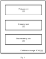
- Fig. 1 illustrates an exemplary diagram of the Conference Manager (CM) for low bandwidth video conferencing, in accordance with some embodiments of the present disclosure.
- the CM 100 includes a producer unit 101, a consumer unit 102, and a data streaming unit 103.
- the producer unit 101 and the consumer unit 102 described herein are the video producer and the video consumer respectively, disclosed in Indian patent application number 201821005659 (title: ADAPTIVE RESTful REAL-TIME LIVE MEDIA STREAMING).
- Indian patent application number 201821005659 title: ADAPTIVE RESTful REAL-TIME LIVE MEDIA STREAMING.
- the CM 100 is configured to host the producer unit 101 and the consumer unit 102, along with other components, and control and synchronize working of the producer unit 101 and the consumer unit 102 at a transmitting end and a receiving end of a communication network during a conference session, in order to facilitate the video conferencing in a low bandwidth network.
- the CM 100 is hosted at the receiving end as well as at the transmitting end.
- the CM 100 at the transmitting end is configured to initiate the conference session by calling the receiving end. If the call is answered by the receiving end, then the CM initiates the producer unit 101 and the consumer unit 102 at the transmitting unit 101, for the purpose of video transmission and video reception respectively.
- the CM 100 checks whether connection between the producer unit 101 at the transmitting end and the consumer unit 102 at the receiving end is successful or not. If the connection is successful, then the video transmission is performed between the producer unit 101 at the transmitting end and the consumer unit 102 at the receiving end. If the connection is unsuccessful, then the CM facilitates only audio communication between the transmitting end and the receiving end, using an associated (audio) communication device, which may be a mobile phone with at least second generation (2G) connectivity.
- an associated (audio) communication device which may be a mobile phone with at least second generation (2G) connectivity.
- CM 100 can be used by the CM 100 to collect the data.
- the CM 100 is deployed for a tele-medicine application in which a doctor examines a patient from a remote location, the doctor would require details regarding certain physiological parameters such as blood sugar level, blood pressure level, heart beat count and so on, in addition to the video and/or audio data, for inspection and diagnosis purpose.
- appropriate sensors can be used for collecting information on various physiological parameters being monitored, and the corresponding data is taken as input by the CM 100 to transmit it to the receiving end.
- CM 100 Various data flow between the CM 100 and other components at the transmitting end, are depicted in Fig. 3a .
- the CM 100 at the transmitting end transmits the audio signal over a Public Switching Telephone Network (PSTN), and the video/sensor data/documents are transmitted over internet connection which may be of low bandwidth i.e. the CM 100 uses a combination of circuit switched and packet switched networks for the purpose of transmitting the data during the conference session.
- PSTN Public Switching Telephone Network
- the CM 100 at the receiving end of the communication network receives the call from the CM 100 at the transmitting end. If the call connection is successfully established, the CM 100 at the receiving end initializes the producer unit 101 and the consumer unit 102 at the receiving end. The producer unit 101 and the consumer unit 102 at the receiving end and the producer unit 101 and the consumer unit 102 at the transmitting end are to be connected to each other for the purpose of the audio/video/sensor data transfer. If the producer unit 101 and the consumer unit 102 at the receiving end and the producer unit 101 and the consumer unit 102 at the transmitting end are not connected, then the CM 100 allows only the audio communication to take place between the transmitting end and the receiving end.
- the CM 100 uses a media mixing unit 204 so as to mix the audio, video, and sensor data being received from the transmitting unit 101.
- One or more suitable mixing circuits may form the mixing unit 204.
- the media mixing unit 204 time-aligns the video data with the corresponding audio data, and then encodes and packages the composite media into a multi-container format, and this data may be uploaded to any associated storage unit (local/remote/cloud). This mechanism is depicted in Fig. 7 .
- the audio signal received from the mobile network and the video/sensor/documents received over the internet are fed as inputs to the mixing unit 204, and output of the mixing unit can be further displayed to one or more person at the receiving end, using one or more appropriate interfaces.
- Various data flow between the CM 100 and other components at the receiving end, are depicted in Fig. 3b .
- the CM 100 is further configured to enable and facilitate a fast block-wise transfer of data between the transmitting end and the receiving end during the conference session.
- the CM 100 enables the fast block-wise data (FBD) transfer if size of the data to be exchanged between the transmitting end and the receiving end exceeds a threshold of data size set in terms of a Maximum Transfer Unit (MTU) for the communication network.
- FBD fast block-wise data
- MTU Maximum Transfer Unit
- all blocks except last block in a message frame corresponding to data being transmitted are sent as non-confirmable requests with a no-response option on a representational state transfer protocol (STP) over a datagram Transport protocol (DTP).
- STP representational state transfer protocol
- DTP datagram Transport protocol
- the last block in the message frame corresponding to data being transmitted is sent as a confirmable request without the no-response option.
- the receiving end Upon receiving the last block (without the no-response option), the receiving end transmits a response message back to the transmitting end. If the response message indicates loss of at least one of the blocks transmitted, the transmitting end identifies position of the at least one block in the message frame and retransmits the at least one block.
- the data transfer is terminated if the response message indicates that all blocks have been received.
- the response message since the response message is sent by the receiving end only after receiving the last block (and not separately for each of the blocks received), amount of load on the network is less. More details pertaining to the FBD transfer is provided with description of Fig. 6 .
- Fig. 2 is a functional block diagram depicting use of the CM in a conferencing system, according to some embodiments of the present disclosure.
- two transceiver units i.e. a first transceiver unit 201 and a second transceiver unit 206 are involved in a conference session.
- the first transceiver unit 201 acts as the transmitting unit and the second transceiver unit 206 acts as the receiving unit.
- the second transceiver unit 206 acts as the transmitting unit and the first transceiver unit 201 acts as the receiving unit.
- both the first transceiver unit 201 and the second transceiver unit 206 act as the transmitting and receiving units in the same conference session (i.e. bi-directional full-duplex communication).
- Each of the transceiver units 201 and 206 include a communication device 202, a visual sensor 203, a media mixing unit 204, and a computing device 205.
- the computing device 205 includes a CM 100.
- the communication device 202 may be any appropriate communication device such as a mobile phone, with at least a 2G network connectivity, and which can capture and transmit audio signals corresponding to the conference session to a receiving end.
- the visual sensor 203 may be a camera that can capture a video corresponding to the conference session. In various embodiments, the visual sensor 203 may be a part of the communication device 202, or may be an independent unit. It is also to be noted that any number of transceiver units can involve/be part of the conference session. For the ease of explanation, only two transceiver units are considered in this embodiment, as depicted in Fig. 2 .
- the CM 100 at the first transceiver unit 201 initializes the producer unit 101, the consumer unit 102, and the data streaming unit 103 when a conference session is started.
- the producer unit 101 captures the video of the patient from the patient location using a visual sensor (a camera), corresponding audio is captured by the communication device 202, and any sensor data to be transmitted is captured by the streaming unit 103 from corresponding sensors.
- the CM 100 at the first transceiver unit transmits the captured video/sensor data/documents if any, over the internet, whereas the audio data is transmitted over a mobile network (PSTN).
- PSTN mobile network
- the consumer unit 102 at the second transceiver unit 206 which is in the doctor's location (a second party), captures the data transmitted by the first transceiver 201.
- the captured audio and video data are mixed using the media mixing unit 204.
- the data which is output of the media mixing unit 204 may be stored in an associated storage space (which may be a cloud based storage system as in Fig.8 ).
- the doctor is then able to view and listen to the contents and the same can be used by the doctor for the purpose of diagnosis.
- the doctor can then advice the patient or someone else sitting at the patient location over the video conferencing.
- the second transceiver unit 206 acts as the transmitting unit and the first transceiver unit 201 acts as the receiving unit.
- a third transceiver unit (not shown in figure) at the location of the specialist doctor can join the conference session, and the audio/video/sensor data/documents and so on can be exchanged.
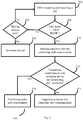
- FIG. 4 is a flow diagram depicting steps involved in initiation activities performed by the CM of FIG. 1 at transmitting end, in accordance with some embodiments of the present disclosure.
- the CM 100 at the transmitting end calls (402) the receiving end. If the call status is not 'OFF-HOOK', which indicates that the receiving end is not available for communication, then the CM 100 at the transmitting end waits for a specific time period, and if the receiving end is still not available even after expiry of the time period, then the call is reattempted. If the call status is 'OFF-HOOK', which indicates that the receiving end is available for communication, the CM 100 starts/initiates (408) the producer unit 101 at the transmitting end and continues the audio conversation.
- the producer unit 101 at the transmitting end tries to establish communication with consumer unit 102 at the receiving end. If the connection is successfully established (410), then the CM 100 triggers (412) producer unit 101-consumer unit 102 communication. If the connection is unsuccessful, then the CM 100 enables (414) audio-only communication.
- FIG. 5 is a flow diagram depicting steps involved in initiation activities performed by the CM of FIG. 1 at receiving end, in accordance with some embodiments of the present disclosure.
- the CM 100 at the receiving end receives (502) a call from the transmitting end. If the call status is not 'OFF-HOOK', which indicates that the transmitting end is not available for communication, then the CM 100 at the receiving end waits for a specific time period, and if the receiving end is still not available even after expiry of the time period, then the call is terminated (508). If the receiving end is available for communication (which is indicated by a call status 'OFF-HOOK'), the CM 100 at the receiving end starts/initiates (510) the consumer unit 101 at the receiving end and continues the audio conversation.
- the consumer unit 102 at the receiving end tries to establish communication with producer unit 101 at the transmitting end. If the connection is successfully established (512), then the CM 100 triggers (514) producer unit 101-consumer unit 101 communication. If the connection is unsuccessful, then the CM 100 enables and continues (516) audio-only communication.
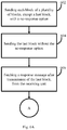
- FIG. 6 is a flow diagram depicting steps involved in the process of fast block-wise transfer being enabled by the CM of FIG. 1 , in accordance with some embodiments of the present disclosure.
- each block/segment of a plurality of blocks in a message frame corresponding to data being transmitted from the transmitting end to the receiving end, except last block, are sent as non-confirmable requests with a no-response option on a representational state transfer protocol (STP) over a datagram Transport protocol (DTP).
- STP representational state transfer protocol
- DTP datagram Transport protocol
- the last block in the message frame corresponding to data being transmitted is sent (604) as a confirmable request without the no-response option.
- the receiving end Upon receiving the last block (without the no-response option), the receiving end transmits a response message back to the transmitting end.
- the transmitting end fetches/collects (606) the response message from the receiving end.
- the response message sent by the receiving end is of a type 'Continue for Lost Segments (CLS)'. If the response message does not contain /is not of CLS type message, then the transmitting end marks the data transmission as successful (610).
- the transmitting end acknowledges (614) the response message, and identifies position of the at least one block in the message frame and retransmits the at least one block/each of the lost segments. Further the block which has been identified as missing/lost is retransmitted by the transmitting end. If any request is timed-out, then the transmitting end terminates (620) the data transfer with a suitable error code.
- the transmitting end After retransmitting all the lost blocks, the transmitting end awaits another response message from the receiving end, and upon receipt of the response message, checks if M-bit is set (which indicates lost blocks). If the response message indicates loss of any block/segment, then the transmitting reiterates steps 614-624. The data transfer is terminated if the response message indicates that all blocks have been received.
- M-bit which indicates lost blocks
- the mechanism of communication disclosed in the Indian patent application number 201821005659 allows data transmission on a low bandwidth network.
- the CM 100 integrates and controls working of the producer unit and the consumer unit at a transmitting and at a receiving end of a communication network so as to facilitate the bi-directional video conferencing.
- the embodiments of present disclosure herein addresses unresolved problem of low bandwidth video conferencing.
- the embodiment thus provides a Conference Manager (CM) which can host a producer unit, a consumer unit, and a data streaming unit which can facilitate the low bandwidth video conferencing.
- CM Conference Manager
- the embodiments herein further provides a mechanism to use the CM in a conference network so as to facilitate the low bandwidth video conferencing between multiple parties involved.
- the hardware device can be any kind of device which can be programmed including e.g. any kind of computer like a server or a personal computer, or the like, or any combination thereof.
- the device may also include means which could be e.g. hardware means like e.g. an application-specific integrated circuit (ASIC), a field-programmable gate array (FPGA), or a combination of hardware and software means, e.g.
- ASIC application-specific integrated circuit
- FPGA field-programmable gate array
- the means can include both hardware means and software means.
- the method embodiments described herein could be implemented in hardware and software.
- the device may also include software means.
- the embodiments may be implemented on different hardware devices, e.g. using a plurality of CPUs.
- the embodiments herein can comprise hardware and software elements.
- the embodiments that are implemented in software include but are not limited to, firmware, resident software, microcode, etc.
- the functions performed by various modules described herein may be implemented in other modules or combinations of other modules.
- a computer-usable or computer readable medium can be any apparatus that can comprise, store, communicate, propagate, or transport the program for use by or in connection with the instruction execution system, apparatus, or device.
- a computer-readable storage medium refers to any type of physical memory on which information or data readable by a processor may be stored.
- a computer-readable storage medium may store instructions for execution by one or more processors, including instructions for causing the processor(s) to perform steps or stages consistent with the embodiments described herein.
- the term "computer-readable medium” should be understood to include tangible items and exclude carrier waves and transient signals, i.e., be non-transitory. Examples include random access memory (RAM), read-only memory (ROM), volatile memory, nonvolatile memory, hard drives, CD ROMs, DVDs, flash drives, disks, and any other known physical storage media.
Landscapes
- Engineering & Computer Science (AREA)
- Signal Processing (AREA)
- Multimedia (AREA)
- Computer Networks & Wireless Communication (AREA)
- General Engineering & Computer Science (AREA)
- Telephonic Communication Services (AREA)
- Two-Way Televisions, Distribution Of Moving Picture Or The Like (AREA)
Abstract
Description
- The present application claims priority from Indian patent application no.
201921003235 - The disclosure herein generally relates to a telecommunication network, and, more particularly, to a Conference Manager (CM) for low bandwidth video conference in the telecommunication network.
- Video conferencing allows two or more parties in different locations to interact with each other by seeing each other, and finds its application in use case scenarios such as personal communication, remote monitoring, tele-medicine and so on. Coverage/signal strength of the telecommunication networks is different in different places. For example, in a city the coverage is usually good and bandwidth and internet speed is also high, whereas in a rural area the coverage and the bandwidth may not be good. During the video conferencing between two parties, if the coverage and bandwidth is not good at location of even one party, it affects quality of the video conferencing session, and may even result in session getting terminated and packet loss.
- While the packet loss and/or the session termination may not be critical if the video conferencing is between two friends, it would be very critical in some other applications. For example, consider tele-medicine domain. In the tele-medicine domain, doctors who are sitting at a remote location can inspect a patient and can suggest medicines. An even more critical application in the tele-medicine domain is remote robot-assisted surgery through video conferencing. In this scenario, the doctor who is at a remote location performs the surgery on a patient using robotic assistance. This requires continuous, uninterrupted, and real-time feed to the doctor from the patient's location, and any network that affects speed/bandwidth may be fatal for the patient.
- Some mechanisms for facilitating low bandwidth communication exist. One of the existing mechanisms identifies characteristics are critical for rendering the media by processing one or more media to be streamed, and then identifies corresponding segments of the media. Further the identified segments are transmitted to destination as reliable requests with guaranteed delivery, and the not so critical segments are transmitted as unreliable requests.
- Embodiments of the present disclosure present technological improvements as solutions to one or more of the above-mentioned technical problems recognized by the inventors in conventional systems. For example, in one embodiment, a Conference Manager (CM), is provided. The CM includes a producer unit, a consumer unit, and a data streaming unit. The CM is configured to handle bi-directional communication between a transmitting end and a receiving end of a communication network the CM is associated with. During this process, at the transmitting end of the communication network, the CM initiates a communication device and a visual sensor at the transmitting end when a conference session is initiated, using the producer unit, and then initiates capturing of an audio signal and a video, using the communication device and the visual sensor. At the receiving end of the communication network, the CM initiates reception of the audio signal and the video from the transmitting end, during the conference session, using the consumer unit. The CM also enables fast block-wise transfer of data, other than the audio signal or the video but related to the conference session, transmitted between the transmitting end and the receiving end to reduce latency if size of the data exceeds a Maximum Transfer Unit (MTU) size of the communication network.
- It is to be understood that both the foregoing general description and the following detailed description are exemplary and explanatory only and are not restrictive of the invention, as claimed.
- The accompanying drawings, which are incorporated in and constitute a part of this disclosure, illustrate exemplary embodiments and, together with the description, serve to explain the disclosed principles:
-
Fig. 1 illustrates an exemplary diagram of the Conference Manager (CM) for low bandwidth video conferencing, in accordance with some embodiments of the present disclosure. -
Fig. 2 is a functional block diagram depicting use of the CM ofFIG. 1 in a conferencing system, in accordance with some embodiments of the present disclosure. -
Fig. 3 illustrates communication between the CM ofFIG. 1 and different components of the conferencing system, in accordance with some embodiments of the present disclosure. -
Fig. 4 is a flow diagram depicting steps involved in initiation activities performed by the CM ofFIG. 1 at transmitting end, in accordance with some embodiments of the present disclosure. -
Fig. 5 is a flow diagram depicting steps involved in initiation activities performed by the CM ofFIG. 1 at receiving end, in accordance with some embodiments of the present disclosure. -
Fig. 6 is a flow diagram depicting steps involved in the process of fast block-wise transfer being enabled by the CM ofFIG. 1 , in accordance with some embodiments of the present disclosure. -
Fig. 7 is a flow diagram depicting steps involved in data packaging by the CM ofFIG. 1 , in accordance with some embodiments of the present disclosure. -
Fig. 8 is an example diagram depicting implementation of the CM ofFIG. 1 in a conferencing system for tele-medicine application, in accordance with some embodiments of the present disclosure. -
Fig. 9 is an example bit arrangement for lost segment indicator used by the CM ofFIG. 1 , in accordance with some embodiments of the present disclosure. - Exemplary embodiments are described with reference to the accompanying drawings. In the figures, the left-most digit(s) of a reference number identifies the figure in which the reference number first appears. Wherever convenient, the same reference numbers are used throughout the drawings to refer to the same or like parts. While examples and features of disclosed principles are described herein, modifications, adaptations, and other implementations are possible without departing from the spirit and scope of the disclosed embodiments. It is intended that the following detailed description be considered as exemplary only, with the true scope and spirit being indicated by the following claims.
- Referring now to the drawings, and more particularly to
FIG. 1 through FIG. 9 , where similar reference characters denote corresponding features consistently throughout the figures, there are shown preferred embodiments and these embodiments are described in the context of the following exemplary system and/or method. -
Fig. 1 illustrates an exemplary diagram of the Conference Manager (CM) for low bandwidth video conferencing, in accordance with some embodiments of the present disclosure. The CM 100 includes aproducer unit 101, aconsumer unit 102, and adata streaming unit 103. - The
producer unit 101 and theconsumer unit 102 described herein are the video producer and the video consumer respectively, disclosed in Indian patent application number201821005659 producer unit 101 and theconsumer unit 102, the entire contents of the patent application number201821005659 - The CM 100 is configured to host the
producer unit 101 and theconsumer unit 102, along with other components, and control and synchronize working of theproducer unit 101 and theconsumer unit 102 at a transmitting end and a receiving end of a communication network during a conference session, in order to facilitate the video conferencing in a low bandwidth network. In a conference system, the CM 100 is hosted at the receiving end as well as at the transmitting end. - The
CM 100 at the transmitting end is configured to initiate the conference session by calling the receiving end. If the call is answered by the receiving end, then the CM initiates theproducer unit 101 and theconsumer unit 102 at the transmittingunit 101, for the purpose of video transmission and video reception respectively. TheCM 100 checks whether connection between theproducer unit 101 at the transmitting end and theconsumer unit 102 at the receiving end is successful or not. If the connection is successful, then the video transmission is performed between theproducer unit 101 at the transmitting end and theconsumer unit 102 at the receiving end. If the connection is unsuccessful, then the CM facilitates only audio communication between the transmitting end and the receiving end, using an associated (audio) communication device, which may be a mobile phone with at least second generation (2G) connectivity. If any additional data such as sensor data, documents and so on are to be transmitted, then appropriate input means at the transmitting end can be used by theCM 100 to collect the data. For example, if theCM 100 is deployed for a tele-medicine application in which a doctor examines a patient from a remote location, the doctor would require details regarding certain physiological parameters such as blood sugar level, blood pressure level, heart beat count and so on, in addition to the video and/or audio data, for inspection and diagnosis purpose. In that scenario, appropriate sensors can be used for collecting information on various physiological parameters being monitored, and the corresponding data is taken as input by theCM 100 to transmit it to the receiving end. Similarly, if any document (in any specific format) is to be sent to the receiving end, the same can be collected and transmitted by theCM 100. Various data flow between theCM 100 and other components at the transmitting end, are depicted inFig. 3a . - In an embodiment, the
CM 100 at the transmitting end transmits the audio signal over a Public Switching Telephone Network (PSTN), and the video/sensor data/documents are transmitted over internet connection which may be of low bandwidth i.e. theCM 100 uses a combination of circuit switched and packet switched networks for the purpose of transmitting the data during the conference session. - The
CM 100 at the receiving end of the communication network receives the call from theCM 100 at the transmitting end. If the call connection is successfully established, theCM 100 at the receiving end initializes theproducer unit 101 and theconsumer unit 102 at the receiving end. Theproducer unit 101 and theconsumer unit 102 at the receiving end and theproducer unit 101 and theconsumer unit 102 at the transmitting end are to be connected to each other for the purpose of the audio/video/sensor data transfer. If theproducer unit 101 and theconsumer unit 102 at the receiving end and theproducer unit 101 and theconsumer unit 102 at the transmitting end are not connected, then theCM 100 allows only the audio communication to take place between the transmitting end and the receiving end. - At the receiving end, the
CM 100 uses amedia mixing unit 204 so as to mix the audio, video, and sensor data being received from the transmittingunit 101. One or more suitable mixing circuits may form themixing unit 204. During the mixing of the audio, video, and other signals, themedia mixing unit 204 time-aligns the video data with the corresponding audio data, and then encodes and packages the composite media into a multi-container format, and this data may be uploaded to any associated storage unit (local/remote/cloud). This mechanism is depicted inFig. 7 . The audio signal received from the mobile network and the video/sensor/documents received over the internet are fed as inputs to themixing unit 204, and output of the mixing unit can be further displayed to one or more person at the receiving end, using one or more appropriate interfaces. Various data flow between theCM 100 and other components at the receiving end, are depicted inFig. 3b . - The
CM 100 is further configured to enable and facilitate a fast block-wise transfer of data between the transmitting end and the receiving end during the conference session. In an embodiment, theCM 100 enables the fast block-wise data (FBD) transfer if size of the data to be exchanged between the transmitting end and the receiving end exceeds a threshold of data size set in terms of a Maximum Transfer Unit (MTU) for the communication network. The steps in the FBD transfer are explained below: - During the FBD transfer, from the transmitting end of the communication network, all blocks except last block in a message frame corresponding to data being transmitted are sent as non-confirmable requests with a no-response option on a representational state transfer protocol (STP) over a datagram Transport protocol (DTP). The last block in the message frame corresponding to data being transmitted is sent as a confirmable request without the no-response option. Upon receiving the last block (without the no-response option), the receiving end transmits a response message back to the transmitting end. If the response message indicates loss of at least one of the blocks transmitted, the transmitting end identifies position of the at least one block in the message frame and retransmits the at least one block. The data transfer is terminated if the response message indicates that all blocks have been received. Here, since the response message is sent by the receiving end only after receiving the last block (and not separately for each of the blocks received), amount of load on the network is less. More details pertaining to the FBD transfer is provided with description of
Fig. 6 . -
Fig. 2 is a functional block diagram depicting use of the CM in a conferencing system, according to some embodiments of the present disclosure. As can be seen inFig. 2 , two transceiver units i.e. afirst transceiver unit 201 and asecond transceiver unit 206 are involved in a conference session. In an embodiment, at an instance thefirst transceiver unit 201 acts as the transmitting unit and thesecond transceiver unit 206 acts as the receiving unit. In another embodiment, at an instance thesecond transceiver unit 206 acts as the transmitting unit and thefirst transceiver unit 201 acts as the receiving unit. In yet another embodiment, both thefirst transceiver unit 201 and thesecond transceiver unit 206 act as the transmitting and receiving units in the same conference session (i.e. bi-directional full-duplex communication). - Each of the
transceiver units communication device 202, avisual sensor 203, amedia mixing unit 204, and acomputing device 205. Thecomputing device 205 includes aCM 100. - The
communication device 202 may be any appropriate communication device such as a mobile phone, with at least a 2G network connectivity, and which can capture and transmit audio signals corresponding to the conference session to a receiving end. Thevisual sensor 203 may be a camera that can capture a video corresponding to the conference session. In various embodiments, thevisual sensor 203 may be a part of thecommunication device 202, or may be an independent unit. It is also to be noted that any number of transceiver units can involve/be part of the conference session. For the ease of explanation, only two transceiver units are considered in this embodiment, as depicted inFig. 2 . - For ease of understanding, consider a video-conference surgery scenario (as depicted in
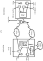
Fig.8 ). Consider that thefirst transceiver unit 201 is located at a patient location (a first party) and thesecond transceiver unit 206 is at a doctor's location. TheCM 100 at thefirst transceiver unit 201 initializes theproducer unit 101, theconsumer unit 102, and thedata streaming unit 103 when a conference session is started. Theproducer unit 101 captures the video of the patient from the patient location using a visual sensor (a camera), corresponding audio is captured by thecommunication device 202, and any sensor data to be transmitted is captured by thestreaming unit 103 from corresponding sensors. TheCM 100 at the first transceiver unit transmits the captured video/sensor data/documents if any, over the internet, whereas the audio data is transmitted over a mobile network (PSTN). - The
consumer unit 102 at thesecond transceiver unit 206, which is in the doctor's location (a second party), captures the data transmitted by thefirst transceiver 201. The captured audio and video data are mixed using themedia mixing unit 204. The data which is output of themedia mixing unit 204 may be stored in an associated storage space (which may be a cloud based storage system as inFig.8 ). The doctor is then able to view and listen to the contents and the same can be used by the doctor for the purpose of diagnosis. The doctor can then advice the patient or someone else sitting at the patient location over the video conferencing. At this stage thesecond transceiver unit 206 acts as the transmitting unit and thefirst transceiver unit 201 acts as the receiving unit. If the doctor requires advice from a specialist doctor, a third transceiver unit (not shown in figure) at the location of the specialist doctor can join the conference session, and the audio/video/sensor data/documents and so on can be exchanged. -
FIG. 4 is a flow diagram depicting steps involved in initiation activities performed by the CM ofFIG. 1 at transmitting end, in accordance with some embodiments of the present disclosure. TheCM 100 at the transmitting end calls (402) the receiving end. If the call status is not 'OFF-HOOK', which indicates that the receiving end is not available for communication, then theCM 100 at the transmitting end waits for a specific time period, and if the receiving end is still not available even after expiry of the time period, then the call is reattempted. If the call status is 'OFF-HOOK', which indicates that the receiving end is available for communication, theCM 100 starts/initiates (408) theproducer unit 101 at the transmitting end and continues the audio conversation. Theproducer unit 101 at the transmitting end tries to establish communication withconsumer unit 102 at the receiving end. If the connection is successfully established (410), then theCM 100 triggers (412) producer unit 101-consumer unit 102 communication. If the connection is unsuccessful, then theCM 100 enables (414) audio-only communication. -
FIG. 5 is a flow diagram depicting steps involved in initiation activities performed by the CM ofFIG. 1 at receiving end, in accordance with some embodiments of the present disclosure. TheCM 100 at the receiving end receives (502) a call from the transmitting end. If the call status is not 'OFF-HOOK', which indicates that the transmitting end is not available for communication, then theCM 100 at the receiving end waits for a specific time period, and if the receiving end is still not available even after expiry of the time period, then the call is terminated (508). If the receiving end is available for communication (which is indicated by a call status 'OFF-HOOK'), theCM 100 at the receiving end starts/initiates (510) theconsumer unit 101 at the receiving end and continues the audio conversation. Theconsumer unit 102 at the receiving end tries to establish communication withproducer unit 101 at the transmitting end. If the connection is successfully established (512), then theCM 100 triggers (514) producer unit 101-consumer unit 101 communication. If the connection is unsuccessful, then theCM 100 enables and continues (516) audio-only communication. -
FIG. 6 is a flow diagram depicting steps involved in the process of fast block-wise transfer being enabled by the CM ofFIG. 1 , in accordance with some embodiments of the present disclosure. - In the Fast Block-wise Data (FBD) transfer, each block/segment of a plurality of blocks in a message frame corresponding to data being transmitted from the transmitting end to the receiving end, except last block, are sent as non-confirmable requests with a no-response option on a representational state transfer protocol (STP) over a datagram Transport protocol (DTP). The last block in the message frame corresponding to data being transmitted is sent (604) as a confirmable request without the no-response option. Upon receiving the last block (without the no-response option), the receiving end transmits a response message back to the transmitting end. The transmitting end fetches/collects (606) the response message from the receiving end. If any of the blocks has been lost during transmission, the response message sent by the receiving end is of a type 'Continue for Lost Segments (CLS)'. If the response message does not contain /is not of CLS type message, then the transmitting end marks the data transmission as successful (610). An example bit arrangement for lost segment indicator is depicted in
FIG. 9 . In the depicted bit arrangement,
N = max message_size
M = more bit
B = lost segment bit-map - If the response message indicates loss of at least one of the blocks transmitted (i.e. the response message contains CLS type), then the transmitting end acknowledges (614) the response message, and identifies position of the at least one block in the message frame and retransmits the at least one block/each of the lost segments. Further the block which has been identified as missing/lost is retransmitted by the transmitting end. If any request is timed-out, then the transmitting end terminates (620) the data transfer with a suitable error code.
- After retransmitting all the lost blocks, the transmitting end awaits another response message from the receiving end, and upon receipt of the response message, checks if M-bit is set (which indicates lost blocks). If the response message indicates loss of any block/segment, then the transmitting reiterates steps 614-624. The data transfer is terminated if the response message indicates that all blocks have been received. Here, since the response message is sent by the receiving end only after receiving the last block (and not separately for each of the blocks received), amount of load on the network is less.
- The mechanism of communication disclosed in the Indian patent application number
201821005659 CM 100 integrates and controls working of the producer unit and the consumer unit at a transmitting and at a receiving end of a communication network so as to facilitate the bi-directional video conferencing. - The written description describes the subject matter herein to enable any person skilled in the art to make and use the embodiments. The scope of the subject matter embodiments is defined by the claims and may include other modifications that occur to those skilled in the art. Such other modifications are intended to be within the scope of the claims if they have similar elements that do not differ from the literal language of the claims or if they include equivalent elements with insubstantial differences from the literal language of the claims.
- The embodiments of present disclosure herein addresses unresolved problem of low bandwidth video conferencing. The embodiment, thus provides a Conference Manager (CM) which can host a producer unit, a consumer unit, and a data streaming unit which can facilitate the low bandwidth video conferencing. Moreover, the embodiments herein further provides a mechanism to use the CM in a conference network so as to facilitate the low bandwidth video conferencing between multiple parties involved.
- It is to be understood that the scope of the protection is extended to such a program and in addition to a computer-readable means having a message therein; such computer-readable storage means contain program-code means for implementation of one or more steps of the method, when the program runs on a server or mobile device or any suitable programmable device. The hardware device can be any kind of device which can be programmed including e.g. any kind of computer like a server or a personal computer, or the like, or any combination thereof. The device may also include means which could be e.g. hardware means like e.g. an application-specific integrated circuit (ASIC), a field-programmable gate array (FPGA), or a combination of hardware and software means, e.g. an ASIC and an FPGA, or at least one microprocessor and at least one memory with software modules located therein. Thus, the means can include both hardware means and software means. The method embodiments described herein could be implemented in hardware and software. The device may also include software means. Alternatively, the embodiments may be implemented on different hardware devices, e.g. using a plurality of CPUs.
- The embodiments herein can comprise hardware and software elements. The embodiments that are implemented in software include but are not limited to, firmware, resident software, microcode, etc. The functions performed by various modules described herein may be implemented in other modules or combinations of other modules. For the purposes of this description, a computer-usable or computer readable medium can be any apparatus that can comprise, store, communicate, propagate, or transport the program for use by or in connection with the instruction execution system, apparatus, or device.
- The illustrated steps are set out to explain the exemplary embodiments shown, and it should be anticipated that ongoing technological development will change the manner in which particular functions are performed. These examples are presented herein for purposes of illustration, and not limitation. Further, the boundaries of the functional building blocks have been arbitrarily defined herein for the convenience of the description. Alternative boundaries can be defined so long as the specified functions and relationships thereof are appropriately performed. Alternatives (including equivalents, extensions, variations, deviations, etc., of those described herein) will be apparent to persons skilled in the relevant art(s) based on the teachings contained herein. Such alternatives fall within the scope and spirit of the disclosed embodiments. Also, the words "comprising," "having," "containing," and "including," and other similar forms are intended to be equivalent in meaning and be open ended in that an item or items following any one of these words is not meant to be an exhaustive listing of such item or items, or meant to be limited to only the listed item or items. It must also be noted that as used herein and in the appended claims, the singular forms "a," "an," and "the" include plural references unless the context clearly dictates otherwise.
- Furthermore, one or more computer-readable storage media may be utilized in implementing embodiments consistent with the present disclosure. A computer-readable storage medium refers to any type of physical memory on which information or data readable by a processor may be stored. Thus, a computer-readable storage medium may store instructions for execution by one or more processors, including instructions for causing the processor(s) to perform steps or stages consistent with the embodiments described herein. The term "computer-readable medium" should be understood to include tangible items and exclude carrier waves and transient signals, i.e., be non-transitory. Examples include random access memory (RAM), read-only memory (ROM), volatile memory, nonvolatile memory, hard drives, CD ROMs, DVDs, flash drives, disks, and any other known physical storage media.
- It is intended that the disclosure and examples be considered as exemplary only, with a true scope and spirit of disclosed embodiments being indicated by the following claims.
Claims (5)
- A Conference Manager (CM) (100), comprising:a producer unit (101);consumer unit (102); anda data streaming unit (103);
wherein the CM (100) is configured to handle bi-directional communication between a transmitting end and a receiving end of a communication network the CM is associated with, comprising:at the transmitting end of the communication network:initiating a communication device and a visual sensor at the transmitting end when a conference session is initiated, by the producer unit (101); andinitiating capturing of an audio signal and a video using the communication device and the visual sensor, by the producer unit (101);at the receiving end of the communication network:
initiating reception of the audio signal and the video from the transmitting end, during the conference session, using the consumer unit (102); andenabling fast block-wise transfer of data transmitted between the transmitting end and the receiving end, other than the audio signal or the video, related to the conference session, to reduce latency if size of the data exceeds a Maximum Transfer Unit (MTU) size of the communication network. - The communication manager (100) as claimed in claim 1, wherein the communication network executes the fast block-wise transfer by:sending (602) all blocks except last block in a message frame corresponding to data being transmitted, as a non-confirmable request with a no-response option on a representational state transfer protocol over a datagram Transport protocol;sending (604) the last block in the message frame corresponding to data being transmitted, as a confirmable request without the no-response option;fetching (606) a response message corresponding to the blocks transmitted, after transmitting the last block;if the response message indicates loss of at least one of the blocks transmitted:identifying position of the at least one block in the message frame; andretransmitting (616) the at least one block; andterminating the data transfer if the response message indicates that all blocks have been received.
- The CM as claimed in claim 1, wherein the CM is used in a conferencing system to facilitate communication between a first party and at least one second party.
- The conferencing system as claimed in claim 3, comprising:a first transceiver unit (201);a communication network; anda second transceiver unit (206);the first transceiver unit (201) comprising:a communication device (202), wherein the communication device captures and transmits a first audio signal from location of the first transceiver unit (201) to the second transceiver unit,and receives a second audio signal from the second transceiver unit;a visual sensor (203), wherein the visual sensor is configured to capture a video of at least one subject which is at the location of the first transceiver unit (201), further wherein the video is transmitted to the second transceiver unit;a computing device (205), comprising:wherein the CM (100) is configured to coordinate capturing of the first audio signal and the video and transmission of the captured first audio signal and the video to the second transceiver unit (206);the Conference Manager (CM), comprising:the producer unit (101), wherein the producer unit (101) is configured to:initiate the communication device (202) and the visual sensor (203) when a conference session is initiated; andinitiate the capturing of the first audio signal and the video;the consumer unit (102), wherein the consumer unit (102) is configured to:
initiate reception of at least one of the second audio signal and a video from the second transceiver unit, during the conference session; anda data streaming unit (103), wherein the data transfer unit enables fast block-wise transfer of any data over the communication network, other than audio signal or the video, related to the conference to reduce latency if size of data exceeds a Maximum Transfer Unit (MTU) size of the communication network;the second transceiver unit (206) comprising:
the Conference Manager (CM), comprising:the producer unit (101); andthe consumer unit (102);wherein the CM is configured to collect and download the first audio signal and the video transmitted by the first transceiver unit. - The conferencing system as claimed in claim 3, wherein the communication network distributes load in transferring the audio signal and the video between a circuit switched network and a packet switched network.
Applications Claiming Priority (1)
| Application Number | Priority Date | Filing Date | Title |
|---|---|---|---|
| IN201921003235 | 2019-01-25 |
Publications (2)
| Publication Number | Publication Date |
|---|---|
| EP3687110A1 true EP3687110A1 (en) | 2020-07-29 |
| EP3687110B1 EP3687110B1 (en) | 2021-11-03 |
Family
ID=69232776
Family Applications (1)
| Application Number | Title | Priority Date | Filing Date |
|---|---|---|---|
| EP20153688.5A Active EP3687110B1 (en) | 2019-01-25 | 2020-01-24 | A conference manager (cm) for low bandwidth video conferencing |
Country Status (2)
| Country | Link |
|---|---|
| US (1) | US11290293B2 (en) |
| EP (1) | EP3687110B1 (en) |
Families Citing this family (1)
| Publication number | Priority date | Publication date | Assignee | Title |
|---|---|---|---|---|
| JP7850562B2 (en) * | 2022-01-31 | 2026-04-23 | 株式会社アイ・オー・データ機器 | Information processing device, information processing method, and program for information processing device |
Citations (1)
| Publication number | Priority date | Publication date | Assignee | Title |
|---|---|---|---|---|
| US20050213730A1 (en) * | 2000-12-26 | 2005-09-29 | Polycom, Inc. | Conference endpoint instructing conference bridge to dial phone number |
Family Cites Families (6)
| Publication number | Priority date | Publication date | Assignee | Title |
|---|---|---|---|---|
| US20020186243A1 (en) | 2001-06-06 | 2002-12-12 | Robert Ellis | Method and system for providing combined video and physiological data over a communication network for patient monitoring |
| US7184602B2 (en) | 2003-05-02 | 2007-02-27 | Microsoft Corp. | System and method for low bandwidth video streaming for face-to-face teleconferencing |
| US8995306B2 (en) * | 2011-04-06 | 2015-03-31 | Cisco Technology, Inc. | Video conferencing with multipoint conferencing units and multimedia transformation units |
| FR2991532B1 (en) * | 2012-06-05 | 2014-07-18 | Thales Sa | TRANSMISSION METHOD IN A MULTI-RECIPIENT NETWORK |
| US9088692B2 (en) * | 2012-06-14 | 2015-07-21 | Polycom, Inc. | Managing the layout of multiple video streams displayed on a destination display screen during a videoconference |
| US10862940B1 (en) * | 2018-07-31 | 2020-12-08 | Glance Networks, Inc. | Low latency live video on a communication session |
-
2020
- 2020-01-24 US US16/752,472 patent/US11290293B2/en active Active
- 2020-01-24 EP EP20153688.5A patent/EP3687110B1/en active Active
Patent Citations (1)
| Publication number | Priority date | Publication date | Assignee | Title |
|---|---|---|---|---|
| US20050213730A1 (en) * | 2000-12-26 | 2005-09-29 | Polycom, Inc. | Conference endpoint instructing conference bridge to dial phone number |
Also Published As
| Publication number | Publication date |
|---|---|
| EP3687110B1 (en) | 2021-11-03 |
| US11290293B2 (en) | 2022-03-29 |
| US20200267010A1 (en) | 2020-08-20 |
Similar Documents
| Publication | Publication Date | Title |
|---|---|---|
| US10187433B2 (en) | Methods and systems for dynamic adjustment of session parameters for effective video collaboration among heterogenous devices | |
| EP2947825A1 (en) | Video communication method, home terminal and home server | |
| EP3679713B1 (en) | Call reconnection | |
| US20170373864A1 (en) | Data transmission method, apparatus, and system | |
| US20210377323A1 (en) | Method and system for responding to video call service | |
| US10530932B2 (en) | Seamless mechanism to connect an active call to another device | |
| CN102984784B (en) | Data are sent by multiple networks | |
| EP2822239A1 (en) | Electronic conference system, bandwidth management method and storage medium in which bandwidth management program is stored | |
| EP3687110B1 (en) | A conference manager (cm) for low bandwidth video conferencing | |
| US20120236927A1 (en) | Transmission apparatus, transmission method, and recording medium | |
| US20080176555A1 (en) | Communication system, server equipment and terminal equipment | |
| CN109963106B (en) | Video image processing method and device, storage medium and terminal | |
| CN104065913B (en) | A kind of instant communication client | |
| EP3783953B1 (en) | Method and system for automatically resuming call after network handover | |
| CN110213272A (en) | Data transmission method and device | |
| CN111193894A (en) | Method and device for establishing data transmission channel, storage medium and system | |
| CN110809330B (en) | Multi-terminal connection establishment method and device, storage medium and electronic device | |
| WO2025130306A1 (en) | Camera apparatus supporting two-way video call | |
| CN114242073B (en) | A method and system for realizing real-time voice human-computer dialogue | |
| US20160182191A1 (en) | Voip system | |
| US8229063B2 (en) | X-ray image reception system | |
| CN107786836A (en) | A kind of audio frequency and video conversation service realizing method and device | |
| US20260075481A1 (en) | Managing call and message continuity (cmc) session | |
| JP2012105017A (en) | Store introduction service system and store terminal | |
| JP5856854B2 (en) | Content transmission method, content transmission apparatus, and content transmission program |
Legal Events
| Date | Code | Title | Description |
|---|---|---|---|
| PUAI | Public reference made under article 153(3) epc to a published international application that has entered the european phase |
Free format text: ORIGINAL CODE: 0009012 |
|
| STAA | Information on the status of an ep patent application or granted ep patent |
Free format text: STATUS: THE APPLICATION HAS BEEN PUBLISHED |
|
| AK | Designated contracting states |
Kind code of ref document: A1 Designated state(s): AL AT BE BG CH CY CZ DE DK EE ES FI FR GB GR HR HU IE IS IT LI LT LU LV MC MK MT NL NO PL PT RO RS SE SI SK SM TR |
|
| AX | Request for extension of the european patent |
Extension state: BA ME |
|
| STAA | Information on the status of an ep patent application or granted ep patent |
Free format text: STATUS: REQUEST FOR EXAMINATION WAS MADE |
|
| 17P | Request for examination filed |
Effective date: 20210127 |
|
| RBV | Designated contracting states (corrected) |
Designated state(s): AL AT BE BG CH CY CZ DE DK EE ES FI FR GB GR HR HU IE IS IT LI LT LU LV MC MK MT NL NO PL PT RO RS SE SI SK SM TR |
|
| GRAP | Despatch of communication of intention to grant a patent |
Free format text: ORIGINAL CODE: EPIDOSNIGR1 |
|
| STAA | Information on the status of an ep patent application or granted ep patent |
Free format text: STATUS: GRANT OF PATENT IS INTENDED |
|
| INTG | Intention to grant announced |
Effective date: 20210514 |
|
| GRAS | Grant fee paid |
Free format text: ORIGINAL CODE: EPIDOSNIGR3 |
|
| GRAA | (expected) grant |
Free format text: ORIGINAL CODE: 0009210 |
|
| STAA | Information on the status of an ep patent application or granted ep patent |
Free format text: STATUS: THE PATENT HAS BEEN GRANTED |
|
| AK | Designated contracting states |
Kind code of ref document: B1 Designated state(s): AL AT BE BG CH CY CZ DE DK EE ES FI FR GB GR HR HU IE IS IT LI LT LU LV MC MK MT NL NO PL PT RO RS SE SI SK SM TR |
|
| REG | Reference to a national code |
Ref country code: GB Ref legal event code: FG4D |
|
| REG | Reference to a national code |
Ref country code: AT Ref legal event code: REF Ref document number: 1444967 Country of ref document: AT Kind code of ref document: T Effective date: 20211115 Ref country code: CH Ref legal event code: EP |
|
| REG | Reference to a national code |
Ref country code: DE Ref legal event code: R096 Ref document number: 602020000867 Country of ref document: DE |
|
| REG | Reference to a national code |
Ref country code: IE Ref legal event code: FG4D |
|
| REG | Reference to a national code |
Ref country code: NL Ref legal event code: FP |
|
| REG | Reference to a national code |
Ref country code: LT Ref legal event code: MG9D |
|
| REG | Reference to a national code |
Ref country code: AT Ref legal event code: MK05 Ref document number: 1444967 Country of ref document: AT Kind code of ref document: T Effective date: 20211103 |
|
| PG25 | Lapsed in a contracting state [announced via postgrant information from national office to epo] |
Ref country code: RS Free format text: LAPSE BECAUSE OF FAILURE TO SUBMIT A TRANSLATION OF THE DESCRIPTION OR TO PAY THE FEE WITHIN THE PRESCRIBED TIME-LIMIT Effective date: 20211103 Ref country code: LT Free format text: LAPSE BECAUSE OF FAILURE TO SUBMIT A TRANSLATION OF THE DESCRIPTION OR TO PAY THE FEE WITHIN THE PRESCRIBED TIME-LIMIT Effective date: 20211103 Ref country code: FI Free format text: LAPSE BECAUSE OF FAILURE TO SUBMIT A TRANSLATION OF THE DESCRIPTION OR TO PAY THE FEE WITHIN THE PRESCRIBED TIME-LIMIT Effective date: 20211103 Ref country code: BG Free format text: LAPSE BECAUSE OF FAILURE TO SUBMIT A TRANSLATION OF THE DESCRIPTION OR TO PAY THE FEE WITHIN THE PRESCRIBED TIME-LIMIT Effective date: 20220203 Ref country code: AT Free format text: LAPSE BECAUSE OF FAILURE TO SUBMIT A TRANSLATION OF THE DESCRIPTION OR TO PAY THE FEE WITHIN THE PRESCRIBED TIME-LIMIT Effective date: 20211103 |
|
| PG25 | Lapsed in a contracting state [announced via postgrant information from national office to epo] |
Ref country code: IS Free format text: LAPSE BECAUSE OF FAILURE TO SUBMIT A TRANSLATION OF THE DESCRIPTION OR TO PAY THE FEE WITHIN THE PRESCRIBED TIME-LIMIT Effective date: 20220303 Ref country code: SE Free format text: LAPSE BECAUSE OF FAILURE TO SUBMIT A TRANSLATION OF THE DESCRIPTION OR TO PAY THE FEE WITHIN THE PRESCRIBED TIME-LIMIT Effective date: 20211103 Ref country code: PT Free format text: LAPSE BECAUSE OF FAILURE TO SUBMIT A TRANSLATION OF THE DESCRIPTION OR TO PAY THE FEE WITHIN THE PRESCRIBED TIME-LIMIT Effective date: 20220303 Ref country code: PL Free format text: LAPSE BECAUSE OF FAILURE TO SUBMIT A TRANSLATION OF THE DESCRIPTION OR TO PAY THE FEE WITHIN THE PRESCRIBED TIME-LIMIT Effective date: 20211103 Ref country code: NO Free format text: LAPSE BECAUSE OF FAILURE TO SUBMIT A TRANSLATION OF THE DESCRIPTION OR TO PAY THE FEE WITHIN THE PRESCRIBED TIME-LIMIT Effective date: 20220203 Ref country code: LV Free format text: LAPSE BECAUSE OF FAILURE TO SUBMIT A TRANSLATION OF THE DESCRIPTION OR TO PAY THE FEE WITHIN THE PRESCRIBED TIME-LIMIT Effective date: 20211103 Ref country code: HR Free format text: LAPSE BECAUSE OF FAILURE TO SUBMIT A TRANSLATION OF THE DESCRIPTION OR TO PAY THE FEE WITHIN THE PRESCRIBED TIME-LIMIT Effective date: 20211103 Ref country code: GR Free format text: LAPSE BECAUSE OF FAILURE TO SUBMIT A TRANSLATION OF THE DESCRIPTION OR TO PAY THE FEE WITHIN THE PRESCRIBED TIME-LIMIT Effective date: 20220204 Ref country code: ES Free format text: LAPSE BECAUSE OF FAILURE TO SUBMIT A TRANSLATION OF THE DESCRIPTION OR TO PAY THE FEE WITHIN THE PRESCRIBED TIME-LIMIT Effective date: 20211103 |
|
| PG25 | Lapsed in a contracting state [announced via postgrant information from national office to epo] |
Ref country code: SM Free format text: LAPSE BECAUSE OF FAILURE TO SUBMIT A TRANSLATION OF THE DESCRIPTION OR TO PAY THE FEE WITHIN THE PRESCRIBED TIME-LIMIT Effective date: 20211103 Ref country code: SK Free format text: LAPSE BECAUSE OF FAILURE TO SUBMIT A TRANSLATION OF THE DESCRIPTION OR TO PAY THE FEE WITHIN THE PRESCRIBED TIME-LIMIT Effective date: 20211103 Ref country code: RO Free format text: LAPSE BECAUSE OF FAILURE TO SUBMIT A TRANSLATION OF THE DESCRIPTION OR TO PAY THE FEE WITHIN THE PRESCRIBED TIME-LIMIT Effective date: 20211103 Ref country code: EE Free format text: LAPSE BECAUSE OF FAILURE TO SUBMIT A TRANSLATION OF THE DESCRIPTION OR TO PAY THE FEE WITHIN THE PRESCRIBED TIME-LIMIT Effective date: 20211103 Ref country code: DK Free format text: LAPSE BECAUSE OF FAILURE TO SUBMIT A TRANSLATION OF THE DESCRIPTION OR TO PAY THE FEE WITHIN THE PRESCRIBED TIME-LIMIT Effective date: 20211103 Ref country code: CZ Free format text: LAPSE BECAUSE OF FAILURE TO SUBMIT A TRANSLATION OF THE DESCRIPTION OR TO PAY THE FEE WITHIN THE PRESCRIBED TIME-LIMIT Effective date: 20211103 |
|
| REG | Reference to a national code |
Ref country code: DE Ref legal event code: R097 Ref document number: 602020000867 Country of ref document: DE |
|
| PG25 | Lapsed in a contracting state [announced via postgrant information from national office to epo] |
Ref country code: MC Free format text: LAPSE BECAUSE OF FAILURE TO SUBMIT A TRANSLATION OF THE DESCRIPTION OR TO PAY THE FEE WITHIN THE PRESCRIBED TIME-LIMIT Effective date: 20211103 |
|
| PLBE | No opposition filed within time limit |
Free format text: ORIGINAL CODE: 0009261 |
|
| STAA | Information on the status of an ep patent application or granted ep patent |
Free format text: STATUS: NO OPPOSITION FILED WITHIN TIME LIMIT |
|
| REG | Reference to a national code |
Ref country code: BE Ref legal event code: MM Effective date: 20220131 |
|
| 26N | No opposition filed |
Effective date: 20220804 |
|
| PG25 | Lapsed in a contracting state [announced via postgrant information from national office to epo] |
Ref country code: LU Free format text: LAPSE BECAUSE OF NON-PAYMENT OF DUE FEES Effective date: 20220124 Ref country code: AL Free format text: LAPSE BECAUSE OF FAILURE TO SUBMIT A TRANSLATION OF THE DESCRIPTION OR TO PAY THE FEE WITHIN THE PRESCRIBED TIME-LIMIT Effective date: 20211103 |
|
| PG25 | Lapsed in a contracting state [announced via postgrant information from national office to epo] |
Ref country code: SI Free format text: LAPSE BECAUSE OF FAILURE TO SUBMIT A TRANSLATION OF THE DESCRIPTION OR TO PAY THE FEE WITHIN THE PRESCRIBED TIME-LIMIT Effective date: 20211103 Ref country code: BE Free format text: LAPSE BECAUSE OF NON-PAYMENT OF DUE FEES Effective date: 20220131 |
|
| PG25 | Lapsed in a contracting state [announced via postgrant information from national office to epo] |
Ref country code: IE Free format text: LAPSE BECAUSE OF NON-PAYMENT OF DUE FEES Effective date: 20220124 |
|
| PG25 | Lapsed in a contracting state [announced via postgrant information from national office to epo] |
Ref country code: IT Free format text: LAPSE BECAUSE OF FAILURE TO SUBMIT A TRANSLATION OF THE DESCRIPTION OR TO PAY THE FEE WITHIN THE PRESCRIBED TIME-LIMIT Effective date: 20211103 |
|
| P01 | Opt-out of the competence of the unified patent court (upc) registered |
Effective date: 20230526 |
|
| PG25 | Lapsed in a contracting state [announced via postgrant information from national office to epo] |
Ref country code: MK Free format text: LAPSE BECAUSE OF FAILURE TO SUBMIT A TRANSLATION OF THE DESCRIPTION OR TO PAY THE FEE WITHIN THE PRESCRIBED TIME-LIMIT Effective date: 20211103 Ref country code: CY Free format text: LAPSE BECAUSE OF FAILURE TO SUBMIT A TRANSLATION OF THE DESCRIPTION OR TO PAY THE FEE WITHIN THE PRESCRIBED TIME-LIMIT Effective date: 20211103 |
|
| PG25 | Lapsed in a contracting state [announced via postgrant information from national office to epo] |
Ref country code: HU Free format text: LAPSE BECAUSE OF FAILURE TO SUBMIT A TRANSLATION OF THE DESCRIPTION OR TO PAY THE FEE WITHIN THE PRESCRIBED TIME-LIMIT; INVALID AB INITIO Effective date: 20200124 |
|
| PG25 | Lapsed in a contracting state [announced via postgrant information from national office to epo] |
Ref country code: TR Free format text: LAPSE BECAUSE OF FAILURE TO SUBMIT A TRANSLATION OF THE DESCRIPTION OR TO PAY THE FEE WITHIN THE PRESCRIBED TIME-LIMIT Effective date: 20211103 |
|
| PG25 | Lapsed in a contracting state [announced via postgrant information from national office to epo] |
Ref country code: MT Free format text: LAPSE BECAUSE OF FAILURE TO SUBMIT A TRANSLATION OF THE DESCRIPTION OR TO PAY THE FEE WITHIN THE PRESCRIBED TIME-LIMIT Effective date: 20211103 |
|
| REG | Reference to a national code |
Ref country code: CH Ref legal event code: U11 Free format text: ST27 STATUS EVENT CODE: U-0-0-U10-U11 (AS PROVIDED BY THE NATIONAL OFFICE) Effective date: 20260201 |
|
| PGFP | Annual fee paid to national office [announced via postgrant information from national office to epo] |
Ref country code: NL Payment date: 20260122 Year of fee payment: 7 |
|
| PGFP | Annual fee paid to national office [announced via postgrant information from national office to epo] |
Ref country code: GB Payment date: 20260126 Year of fee payment: 7 |
|
| PGFP | Annual fee paid to national office [announced via postgrant information from national office to epo] |
Ref country code: DE Payment date: 20260127 Year of fee payment: 7 |
|
| PGFP | Annual fee paid to national office [announced via postgrant information from national office to epo] |
Ref country code: FR Payment date: 20260126 Year of fee payment: 7 |
|
| PGFP | Annual fee paid to national office [announced via postgrant information from national office to epo] |
Ref country code: CH Payment date: 20260201 Year of fee payment: 7 |