EP3686948B1 - Battery module and battery pack - Google Patents
Battery module and battery pack Download PDFInfo
- Publication number
- EP3686948B1 EP3686948B1 EP19180572.0A EP19180572A EP3686948B1 EP 3686948 B1 EP3686948 B1 EP 3686948B1 EP 19180572 A EP19180572 A EP 19180572A EP 3686948 B1 EP3686948 B1 EP 3686948B1
- Authority
- EP
- European Patent Office
- Prior art keywords
- electrode
- battery module
- battery
- gap
- side wall
- Prior art date
- Legal status (The legal status is an assumption and is not a legal conclusion. Google has not performed a legal analysis and makes no representation as to the accuracy of the status listed.)
- Active
Links
Images


Classifications
-
- H—ELECTRICITY
- H01—ELECTRIC ELEMENTS
- H01M—PROCESSES OR MEANS, e.g. BATTERIES, FOR THE DIRECT CONVERSION OF CHEMICAL ENERGY INTO ELECTRICAL ENERGY
- H01M10/00—Secondary cells; Manufacture thereof
- H01M10/04—Construction or manufacture in general
- H01M10/0431—Cells with wound or folded electrodes
-
- H—ELECTRICITY
- H01—ELECTRIC ELEMENTS
- H01M—PROCESSES OR MEANS, e.g. BATTERIES, FOR THE DIRECT CONVERSION OF CHEMICAL ENERGY INTO ELECTRICAL ENERGY
- H01M10/00—Secondary cells; Manufacture thereof
- H01M10/04—Construction or manufacture in general
- H01M10/0481—Compression means other than compression means for stacks of electrodes and separators
-
- H—ELECTRICITY
- H01—ELECTRIC ELEMENTS
- H01M—PROCESSES OR MEANS, e.g. BATTERIES, FOR THE DIRECT CONVERSION OF CHEMICAL ENERGY INTO ELECTRICAL ENERGY
- H01M10/00—Secondary cells; Manufacture thereof
- H01M10/04—Construction or manufacture in general
- H01M10/0472—Vertically superposed cells with vertically disposed plates
-
- H—ELECTRICITY
- H01—ELECTRIC ELEMENTS
- H01M—PROCESSES OR MEANS, e.g. BATTERIES, FOR THE DIRECT CONVERSION OF CHEMICAL ENERGY INTO ELECTRICAL ENERGY
- H01M10/00—Secondary cells; Manufacture thereof
- H01M10/05—Accumulators with non-aqueous electrolyte
- H01M10/058—Construction or manufacture
- H01M10/0587—Construction or manufacture of accumulators having only wound construction elements, i.e. wound positive electrodes, wound negative electrodes and wound separators
-
- H—ELECTRICITY
- H01—ELECTRIC ELEMENTS
- H01M—PROCESSES OR MEANS, e.g. BATTERIES, FOR THE DIRECT CONVERSION OF CHEMICAL ENERGY INTO ELECTRICAL ENERGY
- H01M50/00—Constructional details or processes of manufacture of the non-active parts of electrochemical cells other than fuel cells, e.g. hybrid cells
- H01M50/10—Primary casings; Jackets or wrappings
- H01M50/102—Primary casings; Jackets or wrappings characterised by their shape or physical structure
- H01M50/103—Primary casings; Jackets or wrappings characterised by their shape or physical structure prismatic or rectangular
-
- H—ELECTRICITY
- H01—ELECTRIC ELEMENTS
- H01M—PROCESSES OR MEANS, e.g. BATTERIES, FOR THE DIRECT CONVERSION OF CHEMICAL ENERGY INTO ELECTRICAL ENERGY
- H01M50/00—Constructional details or processes of manufacture of the non-active parts of electrochemical cells other than fuel cells, e.g. hybrid cells
- H01M50/10—Primary casings; Jackets or wrappings
- H01M50/116—Primary casings; Jackets or wrappings characterised by the material
- H01M50/117—Inorganic material
- H01M50/119—Metals
-
- H—ELECTRICITY
- H01—ELECTRIC ELEMENTS
- H01M—PROCESSES OR MEANS, e.g. BATTERIES, FOR THE DIRECT CONVERSION OF CHEMICAL ENERGY INTO ELECTRICAL ENERGY
- H01M50/00—Constructional details or processes of manufacture of the non-active parts of electrochemical cells other than fuel cells, e.g. hybrid cells
- H01M50/10—Primary casings; Jackets or wrappings
- H01M50/131—Primary casings; Jackets or wrappings characterised by physical properties, e.g. gas permeability, size or heat resistance
- H01M50/133—Thickness
-
- H—ELECTRICITY
- H01—ELECTRIC ELEMENTS
- H01M—PROCESSES OR MEANS, e.g. BATTERIES, FOR THE DIRECT CONVERSION OF CHEMICAL ENERGY INTO ELECTRICAL ENERGY
- H01M50/00—Constructional details or processes of manufacture of the non-active parts of electrochemical cells other than fuel cells, e.g. hybrid cells
- H01M50/10—Primary casings; Jackets or wrappings
- H01M50/147—Lids or covers
-
- H—ELECTRICITY
- H01—ELECTRIC ELEMENTS
- H01M—PROCESSES OR MEANS, e.g. BATTERIES, FOR THE DIRECT CONVERSION OF CHEMICAL ENERGY INTO ELECTRICAL ENERGY
- H01M50/00—Constructional details or processes of manufacture of the non-active parts of electrochemical cells other than fuel cells, e.g. hybrid cells
- H01M50/20—Mountings; Secondary casings or frames; Racks, modules or packs; Suspension devices; Shock absorbers; Transport or carrying devices; Holders
- H01M50/204—Racks, modules or packs for multiple batteries or multiple cells
- H01M50/207—Racks, modules or packs for multiple batteries or multiple cells characterised by their shape
- H01M50/209—Racks, modules or packs for multiple batteries or multiple cells characterised by their shape adapted for prismatic or rectangular cells
-
- H—ELECTRICITY
- H01—ELECTRIC ELEMENTS
- H01M—PROCESSES OR MEANS, e.g. BATTERIES, FOR THE DIRECT CONVERSION OF CHEMICAL ENERGY INTO ELECTRICAL ENERGY
- H01M10/00—Secondary cells; Manufacture thereof
- H01M10/04—Construction or manufacture in general
- H01M10/0463—Cells or batteries with horizontal or inclined electrodes
-
- H—ELECTRICITY
- H01—ELECTRIC ELEMENTS
- H01M—PROCESSES OR MEANS, e.g. BATTERIES, FOR THE DIRECT CONVERSION OF CHEMICAL ENERGY INTO ELECTRICAL ENERGY
- H01M2220/00—Batteries for particular applications
- H01M2220/20—Batteries in motive systems, e.g. vehicle, ship, plane
-
- Y—GENERAL TAGGING OF NEW TECHNOLOGICAL DEVELOPMENTS; GENERAL TAGGING OF CROSS-SECTIONAL TECHNOLOGIES SPANNING OVER SEVERAL SECTIONS OF THE IPC; TECHNICAL SUBJECTS COVERED BY FORMER USPC CROSS-REFERENCE ART COLLECTIONS [XRACs] AND DIGESTS
- Y02—TECHNOLOGIES OR APPLICATIONS FOR MITIGATION OR ADAPTATION AGAINST CLIMATE CHANGE
- Y02E—REDUCTION OF GREENHOUSE GAS [GHG] EMISSIONS, RELATED TO ENERGY GENERATION, TRANSMISSION OR DISTRIBUTION
- Y02E60/00—Enabling technologies; Technologies with a potential or indirect contribution to GHG emissions mitigation
- Y02E60/10—Energy storage using batteries
-
- Y—GENERAL TAGGING OF NEW TECHNOLOGICAL DEVELOPMENTS; GENERAL TAGGING OF CROSS-SECTIONAL TECHNOLOGIES SPANNING OVER SEVERAL SECTIONS OF THE IPC; TECHNICAL SUBJECTS COVERED BY FORMER USPC CROSS-REFERENCE ART COLLECTIONS [XRACs] AND DIGESTS
- Y02—TECHNOLOGIES OR APPLICATIONS FOR MITIGATION OR ADAPTATION AGAINST CLIMATE CHANGE
- Y02P—CLIMATE CHANGE MITIGATION TECHNOLOGIES IN THE PRODUCTION OR PROCESSING OF GOODS
- Y02P70/00—Climate change mitigation technologies in the production process for final industrial or consumer products
- Y02P70/50—Manufacturing or production processes characterised by the final manufactured product
Definitions
- the present disclosure relates to a technical filed of battery, and particularly relates to a battery module and a battery pack.
- the secondary battery is also called as a power battery and is a rechargeable battery.
- the secondary battery are used widely.
- the secondary batteries with a low capacity can be used for a small electric vehicle, while the secondary batteries with a high capacity can be used for a large electric vehicle such as a hybrid vehicle or an electric vehicle.
- a busbar is necessary to connect the respective secondary batteries in series or in parallel.
- the busbar is welded to positive electrodes and negative electrodes of the sedentary batteries.
- a battery module includes a plurality of secondary batteries and connecting members for fixing the plurality of secondary batteries.
- a secondary battery mainly includes a case, an electrode assembly and a cap assembly, wherein the electrode assembly is formed by winding or stacking a positive electrode plate, a negative electrode plate and a separator.
- the electrode assembly included in the secondary battery may expand, and thus release a large expansion force to outside.
- the connecting members Since the plurality of secondary batteries included in the battery module are arranged side by side in one direction and the expansion force released by the electrode assembly is in the arrangement direction of the secondary batteries, a large combined force will be formed by the superposition of the expansion forces released by the electrode assemblies included in the plurality of secondary batteries. This not only will cause deterioration of electrical performance of the secondary battery, but also requires the connecting members to have a high structural strength to restrain and offset the expansion force, which generally is achieved volume of the connecting member, and in turn will reduce energy density and space utilization of the secondary battery.
- WO 2017/190907A1 discloses a battery pack including a thermally conductive plate that can be cooled or heated, and an array of electrochemical cells.
- the cells include a stacked or rolled arrangement of electrode plates, and a current collector disposed in the battery cell that forms an electrical connection with the electrode plates and provides a thermal conduction pathway for conducting heat from the electrode plates to the thermally conductive plate.
- KR 20170050875 A1 provides a secondary battery alleviating pressure generated when the secondary battery expands during charging and discharging.
- the secondary battery includes: an electrode assembly; a support plate placed to face the electrode assembly while interposing the electrode assembly; an elastic member connecting an end part of the support plate; and a case accommodating a support band, the support plate and the electrode assembly.
- the embodiments of the present disclosure provide a battery module and a battery pack.
- the battery module has a small expansion amount in an arrangement direction of secondary batteries, and thus can effectively improve safety during use.
- the embodiments of the present invention provide a battery module, comprising: two or more secondary batteries arranged side by side in a first direction, each of which includes a case, an electrode assembly and a closing portion, wherein the case has a receiving hole comprising an opening and extending in a second direction, and the first direction intersects with the second direction, wherein the closing portion is sealingly connected with the case to close the opening, the electrode assembly is disposed in the receiving hole and includes two or more electrode units, the electrode unit includes a first electrode plate, a second electrode plate and a separator, and the two or more electrode units are stacked in the second direction, wherein the electrode unit is formed by winding the first electrode plate, the second electrode plate and the separator, and the electrode unit is formed into a flat shape and has two wide sides and two narrow sides, wherein the two narrow sides are connected to two opposite ends of the wide side in the first direction respectively, the wide side is disposed opposite to the closing portion, and the wide side has an area larger than that of the narrow side; and the case includes a first
- a ratio of the area of the narrow side to that of the wide side is in a range of 1/10 ⁇ 1/2.
- the first electrode plates in adjacent two layers have a first gap corresponding to the narrow side, and the first gap has a dimension of 5 ⁇ m to 50 ⁇ m.
- the first electrode plates in adjacent two layers have a first gap corresponding to the narrow side and a second gap corresponding to the wide side, wherein the first gap has a dimension greater than that of the second gap.
- the case is made of a material of metal.
- a third gap is provided between the narrow side and the first side wall, and the third gap has a dimension of 0.3 mm to 0.9 mm.
- the first side wall and the second side wall each has a thickness less than that of the bottom wall.
- the closing portion includes a cap plate and electrode terminals, all of which are located at one side of the electrode assembly in the second direction, wherein the cap plate is connected to the case, and the electrode terminals are disposed on the cap plate and electrically connected to the electrode assembly.
- the battery module further comprises a first end plate and a second end plate spaced apart from each other in the first direction, wherein the two or more secondary batteries are disposed between the first end plate and the second end plate, and the first end plate and the second end plate each has a Young's modulus less than 30 Gpa.
- the battery module according to the embodiments of the present disclosure includes two or more secondary batteries arranged side by side in the first direction.
- the electrode units included in the respective secondary batteries are stacked in the receiving hole of the case in the second direction.
- the electrode unit of the present embodiment expands, it mainly expands and deforms in the second direction, while with a small expansion amount in the first direction.
- the combined expansion force in the first direction accumulated by the respective secondary batteries is small.
- the battery module does not need a structural member with high strength to restrain and offset the expansion force, or merely needs a structural member with low strength to restrain and offset the expansion force, which can effectively reduce a mass of the entire battery module, make the battery module to be more compact and effectively increase energy density of the battery module.
- the battery module has a small expansion amount in the first direction, safety of the battery module during use can be effectively improved.
- the embodiments of the present disclosure provides a battery pack, comprises a housing having a receiving chamber; and the battery module according to the above embodiments, wherein the battery module is accommodated in the receiving chamber.
- the housing in the second direction, has a first height greater than a second height of the secondary battery and less than twice of the second height of the secondary battery.
- the battery pack comprises two to six battery modules arranged in a width direction of the housing, and each of the battery modules comprises 20 to 32 secondary batteries.
- the secondary battery has a thickness of 50 mm or more, and the secondary battery has a height of 80 mm or more.
- a battery module 10 according to the embodiments of the present disclosure will be described in detail below by reference to Fig. 1 to Fig. 7 .
- the embodiments of the present disclosure provide a battery module 10, comprising two or more secondary batteries 11 according to the present embodiment and busbars, each of which is used for connecting two secondary batteries 11.
- the two or more secondary batteries 11 are arranged side by side in a first direction X, wherein the first direction X is an arrangement direction of the two or more secondary batteries 11.
- One end of the busbar is fixedly connected to one of the two secondary batteries 11, and the other end of the busbar is fixedly connected to the other one of the two secondary batteries 11.
- the secondary battery 11 may be a battery of hard case or soft package.
- the secondary battery 11 includes a case 12, an electrode assembly 13 disposed in the case 12, and a closing portion sealingly connected with the case 12.
- the case 12 of the present embodiment may be formed in a shape of a quadrangular prism or other shapes.
- the case 12 has an internal space for accommodating the electrode assembly 13 and an electrolyte therein.
- the case 12 can be made of a material such as aluminum, aluminum alloy and plastic.
- the electrode assembly 13 of the present embodiment includes two or more electrode units 14.
- the electrode unit 14 of the present embodiment can be formed by stacking or winding a first electrode plate 141, a second electrode plate 142 and a separator 143, and be formed to have a body portion and a tab connected with the body portion.
- the separator 143 is an insulator interposed between the first electrode plate 141 and the second electrode plate 142.
- the electrode unit 14 of the present embodiment is formed by winding the separator 143, the first electrode plate 141 and the second electrode plate 142, and is formed into a flat shape comprising multiple loops.
- the description is made by exemplarily taking the first electrode plate 141 as a positive electrode plate and taking the second electrode plate 142 as a negative electrode plate.
- the first electrode plate 141 may be a negative electrode plate while the second electrode plate 142 is a positive electrode plate.
- a positive active material is coated on a coating region of the positive electrode plate while a negative active material is coated on a coating region of the negative electrode plate.
- a plurality of uncoated regions extending from the body portion serve as the tab.
- the electrode unit 14 includes two tabs, a positive tab and a negative tab, wherein the positive tab is formed by stacking the plurality of uncoated regions extending from the coated region of the positive electrode plate, and the negative tab is formed by stacking the plurality of uncoated regions extending from the coated region of the negative electrode plate.
- the active material layer included in the electrode unit 14 of the present embodiment will expand, thereby causing the entire electrode unit 14 to expand.
- the electrode unit of the present embodiment has a capacity of 50 Ah to 300 Ah.
- the closing portion of the present disclosure may be an aluminum plastic film formed of aluminum alloy, plastic, nylon, or the like, or may be a cap assembly 15 made of a material such as metal.
- the closing portion of the present embodiment is the cap assembly 15, which includes a cap plate 151 and electrode terminals 152. All of the cap plate 151 and the electrode terminals 152 are located on one side of the electrode assembly 13 in a second direction Y.
- the cap assembly 15 is sealingly connected to the case 12 by the cap plate 151.
- the electrode terminals 152 are disposed on the cap plate 151 and are electrically connected to the electrode assembly 13.
- the battery module of the present embodiment includes two or more secondary batteries 11.
- the two or more secondary batteries 11 are arranged side by side in the first direction X.
- the secondary battery 11 includes the case 12 with the receiving hole 12a, and the electrode assembly 13 disposed in the receiving hole 12a, wherein the receiving hole 12a has the opening and extends in the second direction Y, that is, the second direction Y is parallel to an extending direction of the receiving hole 12a.
- the electrode assembly 13 includes two or more electrode units 14, which are stacked in the second direction Y, wherein the second direction Y is parallel to the stacking direction of the two or more electrode units 14.
- the second direction Y is perpendicular to the first direction X, and also is perpendicular to an extending direction of the opening of the receiving hole 12a and that of the closing portion. It can be easily understood that, in the present embodiment, the second direction Y may intersect with and be approximately perpendicular to the first direction X, and the second direction Y may intersect with and be approximately perpendicular to the extending direction of the opening of the receiving hole 12a and that of the closing portion. If the electrode unit 14 of the present embodiment expands, the electrode assembly 13 may generate a first expansion force in the first direction X and a second expansion force in the second direction Y. Since the plurality of the electrode units 14 are stacked, the first expansion force is smaller than the second expansion force.
- the electrode assembly 13 will expand primarily in the second direction Y, and the primary expansion force of the electrode assembly 13 is in the second direction Y.
- the first expansion force of the electrode assembly 13 is small, and thus has a little affection on the case 12.
- the two or more secondary batteries 11 of the present embodiment are arranged side by side in the first direction X, since the second expansion force generated by each secondary battery 11 due to the expansion thereof has a direction intersecting with the first direction X, that is, the second expansion force generated by each secondary battery 11 due to the expansion thereof is in the second direction Y, a large combined force will not be formed by superposition of the second expansion forces generated by the respective secondary batteries 11 in the first direction X.
- the electrode unit 14 includes a wide side 14a and a narrow side 14b.
- the wide side 14a is disposed opposite to the closing portion, which is not limited to the situation that the wide side 14a and a surface of the closing portion towards the wide side 14a are completely opposite to each other in a strict sense, and also includes the situation that the both are opposite to each other partially, and the situation that the both are opposite to each other with the wide side 14a being arched due to expansion and the surface of the closing portion towards the wide side 14a being flat.
- the narrow side 14b is located on one end of the wide side 14a in the first direction X, where the wide side 14a has two opposite ends in the first direction X, and one narrow side 14b is connected to one end of the wide side 14a.
- the wide side 14a has an area larger than that of the narrow side 14b.
- the expansion force generated by the wide side 14a is larger than that generated by the narrow side 14b, which can further reduce the expansion force of the secondary battery 11 in the first direction X.
- a ratio of the area of the narrow side 14b to the area of the wide side 14a is in a range of 1/10-1/2. If the ratio is greater than 1/2, the area of the narrow side 14b is too large, resulting in that the combined force of the first expansion forces is too large; if the ratio is less than 1/10, the area of the wide side 14a is too large in the case where the capacity of the secondary battery 11 is constant, which leads to difficulties in the infiltration of the electrolyte.
- the electrode unit 14 of the present embodiment is preferably formed by winding the first electrode plate 141, a second electrode plate 142 and a separator 143.
- the electrode unit 14 of the present embodiment is formed into a flat shape.
- the electrode unit 14 includes two winding end faces opposite to each other and a winding axis perpendicular to the winding end faces. Referring to Fig. 3 , the electrode unit 14 includes a wide side 14a and a narrow side 14b, wherein the narrow side 14b at least partially includes an arc region, and there are two wide sides 14a and two narrow sides 14b.
- the two wide sides 14a are disposed opposite to each other in the second direction Y, and each extends perpendicular to the second direction Y; and the two narrow sides 14b are disposed opposite to each other in the first direction X and are respectively connected to two opposite ends of each wide side 14a in the first direction.
- the wide sides 14a and the narrow sides 14b are alternately arranged around the winding axis of the electrode unit 14. Adjacent two electrode units 14 are disposed with their respective wide sides 14a being contact with each other.
- both the wide side 14a and the narrow side 14b expand.
- the wide side 14a expand in the second direction Y, and has a larger expansion amount than the narrow side 14b.
- the wide side 14a is in a flat shape while the narrow side 14b is in an arc shape.
- the electrode unit 14 formed by winding in the present embodiment has multiple layers of the first electrode plates 141 in a radial direction.
- the first electrode plates 141 in adjacent two layers have a first gap 16 corresponding to the narrow side 14b, and have a second gap 17 corresponding to the wide side 14a.
- both a dimension L1 of the first gap 16 and a dimension L2 of the second gap 17 refer to a sum of gaps between the separator 143 and the first electrode plate 141 and gaps between the separator 143 and the second electrode plate 142.
- each layer of the first electrode plates 141 will displace in the radial direction of the electrode unit 14 due to the expansion force.
- Both of the first gap 16 and the second gap 17 can absorb the displacement of each layer of the first electrode plates 141, which can effectively reduce an amount of expansion displacement of the narrow side 14b and the wide side 14a of the electrode unit 14, thereby effectively reducing the expansion force released by the entire electrode unit 14 in various directions.
- the dimension L1 of the first gap 16 is greater than the dimension L2 of the second gap 17, so that the first gap 16 can absorb more expansion displacement of the first electrode plate 141 than the second gap 17.
- the narrow side 14b of the electrode unit 14 has a smaller amount of expansion displacement than the wide side 14a of the electrode unit 14, and thus can reduce the accumulation of the expansion force in the first direction X to a greater extent.
- the first gap 16 and the second gap 17 are defined by gaps between the same two layers of the first electrode plates 141.
- the first gap 16 has the dimension L1 of 5 ⁇ m to 50 ⁇ m. If the dimension L1 of the first gap 16 is less than 5 ⁇ m, the narrow side 14b of the electrode unit 14 will contact the case 12 earlier when the electrode unit 14 expands, resulting in that the electrode unit 14 will receive a larger reaction force when it continues to expand after the narrow side 14b has contacted the case 12.
- the case 12 is preferably made of a material of metal.
- the case 12 includes a first side wall 121, a second side wall 122 and a bottom wall 123 connected to the first side wall 121 and the second side wall 122.
- the cap assembly 15 is disposed opposite to the bottom wall 123 in the second direction Y.
- the cap assembly 15 is sealingly connected to the first side wall 121 and the second side wall 122.
- the first side wall 121 has an area larger than that of the second side wall 122, and also larger than that of the bottom wall 123.
- Adjacent two secondary batteries 11 are disposed with the first side walls 121 opposite to each other. Referring to Fig. 4 or Fig.
- the narrow side 14b is disposed corresponding to the first side wall 121.
- the narrow side 14b of the electrode unit 14 may also expand, but with a small expansion amount, and thus, a compressive force exerted on the first side wall 121 by the narrow side 14b is small. Therefore, a combined force of the expansion forces from the respective secondary batteries 11 in the first direction X is small. Further, since the first side wall 121 has a larger area, the deformation of the first side wall 121 can be reduced. Meanwhile, the larger the expansion amount of the electrode unit 14, the less the dimension L1 of the first gap 16 and the dimension L2 of the second gap 17.
- the electrode unit 14 consumes its internal electrolyte, and thus it is necessary to continuously replenish the electrolyte from the outside.
- the first side wall 121 will restrain the narrow side 14b, causing the first gap 16 to become smaller. This will cause that the electrolyte in the case 12 is difficult to be replenished to an interior of the electrode unit 14 through the first gap 16, thereby adversely affecting the electrical performance of the electrode unit 14.
- the first electrode plate 141 or the second electrode plate 142 located at the outermost layer will be subjected to a relatively large tensile stress, and thus is easy to be broken.
- the first side wall 121 of the present embodiment can restrain the narrow side 14b and prevent a too much expansion of the narrow side 14b, thereby effectively reducing a possibility of breakage of the first electrode plate 141 or the second electrode plate 142.
- the first side walls 121 and the second side walls 122 are alternately arranged, forming a cylindrical member with a rectangular cross section.
- the bottom wall 123 is formed into a plate of a rectangular shape, and is sealingly connected with the first side wall 121 and the second side wall 122.
- a third gap 18 is provided between the narrow side 14b and the first side wall 121.
- the third gap 18 has a dimension L3 of 0.3 mm to 0.9 mm. If the dimension L3 of the third gap is less than 0.3 mm, the narrow side 14b of the electrode unit 14 will completely invade the third gap 18, contact and exert a compressive force on the first side wall 121, even when the narrow side 14b expands to a small extent.
- each of the first side wall 121 and the second side wall 122 has a thickness less than a thickness M of the bottom wall 123. Since the main expansion direction of the electrode unit 14 of the present embodiment is in the second direction Y, the electrode unit 14 exerts a larger force on the bottom wall 123 than the first side wall 121 and the second side wall 122 when the electrode unit 14 expands. Increasing the thickness M of the bottom wall 123 can enhance a strength of the bottom wall 123, increase the constraint on the electrode unit 14, and improve deformation resistance of the bottom wall 123. In the embodiment in which the wide side 14a of the electrode unit 14 faces the bottom wall 123, the bottom wall 123 can restrain the expansion of the electrode unit 14, so that the electrode unit 14 cannot expand too much.
- the first gap 16 will not be completely invaded and disappear, thereby ensuring sufficient electrolyte in the first gap 16.
- reducing the thickness of the first side wall 121 and that of the second side wall 122 is beneficial to reduce a weight of the entire secondary battery 11 and thereby conducive to improving the energy density of the secondary battery 11 and the battery module 10.
- the battery module 10 of the present embodiment further includes a first end plate 19 and a second end plate 20, which are spaced apart from each other in the first direction X.
- Two or more secondary batteries 11 are disposed between the first end plate 19 and the second end plate 20.
- the first end plate 19 and the second end plate 20 each has a Young's modulus less than 30 GPa.
- the first end plate 19 and the second end plate 20 each can have a smaller thickness in the first direction X, and the rigidity and strength requirements on the first end plate 19 and the second plate 20 also can be lowered, which is beneficial to reduce weights of the first end plate 19 and the second end plate 20, and also is beneficial to improve the energy density of the secondary battery 11 and the battery module 10. Moreover, limits on materials of the first end plate 19 and the second end plate 20 also can be reduced, and the materials of the first end plate 19 and the second end plate 20 can be selected from a wider range, which can reduce manufacturing difficulties and costs.
- the battery module 10 further includes a connecting member that is connected to both of the first end plate 19 and the second end plate 20.
- the connecting member can fasten the first end plate 19 and the second end plate 20, thereby fastening the respective secondary batteries 11, and improving positional stability of the respective secondary batteries 11.
- the battery module 10 includes two or more secondary batteries 11 arranged side by side in the first direction X.
- the electrode units 14 included in the respective secondary batteries 11 are stacked in the second direction Y.
- the electrode unit 14 of the present embodiment expands, it mainly expands and deforms in the second direction Y, while with a small expansion amount in the first direction X.
- the combined expansion force in the first direction X of the expansion forces of the respective secondary batteries 11 is small.
- the battery module 10 does not need a structural member with high strength to restrain and offset the expansion force, or merely needs a structural member with low strength to restrain and offset the expansion force, which can effectively reduce a mass of the entire the battery module 10, make the battery module 10 to be more compact and effectively increase the energy density of the battery module 10. Meanwhile, since the battery module 10 has a small expansion amount in the first direction X, safety of the battery module during use can be effectively improved.
- an embodiment of the present disclose further provides a battery pack 30.
- the battery pack 30 can be applied to a vehicle such as an automobile.
- the automobile has a receiving housing for accommodating the battery pack 30, and the receiving housing is generally located at the bottom of the automobile. Since a chassis of the automobile is close to the ground and a height of the receiving housing determines a height space of the automobile, it is necessary to lengthen the receiving housing in a longitudinal direction or a width direction of the automobile, to reduce the height space of the automobile, which means lengths of the battery pack 30 and the battery module 10 are correspondingly lengthened, and the expansion force in the length direction will increase correspondingly.
- the battery pack 30 not only can reduce an occupation space in the height direction of the automobile, but also can have an expansion force not too large in the length direction of itself.
- the height direction of the automobile is parallel to the second direction Y, and one of the longitudinal direction or the width direction of the automobile is the same as the first direction X.
- the battery pack 30 of the present embodiment includes a housing 31 and the battery module 10 of the above embodiments disposed in the housing 31. There may be one battery module 10, or two or more battery modules 10.
- the housing 31 of the present embodiment has a receiving chamber 31a for accommodating the battery module 10.
- the housing 31 includes an upper cover 311 and a lower case 312, which can be sealingly connected to each other to seal the battery module 10 within the receiving chamber 31a.
- the battery module 10 accommodated in the receiving chamber 31a can be fixedly connected to the lower case 312.
- the housing 31 has a first height N greater than a second height H of the secondary battery 11 and less than twice of the second height H of the secondary battery 11, wherein the height of the housing 31 is in the same direction as the second direction Y.
- a gap is reserved between the housing 31 and the respective secondary batteries 11 of the battery module 10.
- the battery pack 30 includes two to six battery modules 10 arranged in a width direction of the housing 31.
- Each of the battery modules 10 includes 20 to 32 secondary batteries 11.
- the width direction of the housing 31 is perpendicular to the first direction X and the second direction Y, and a length direction of the housing 31 is the same as the first direction X. Since the secondary battery 11 of the present embodiment has a small expansion amount in the first direction X, more secondary batteries 11 can be arranged side by side in the first direction X, thereby greatly increasing the energy density of the battery module 10.
- the secondary battery 11 has a thickness D (as shown in Fig. 2 ) of 50 mm or more, and a height H (as shown in Fig. 4 ) of 80 mm or more.
- the thickness of the secondary battery 11 has a same direction as the first direction X, and the height of the secondary battery 11 has a same direction as the second direction Y.
- the battery pack 30 of the present embodiment includes a housing 31 and a battery module 10.
- the battery module 10 When expanding, the battery module 10 has a small expansion amount in the length direction of the housing 31, and thus will release a small expansion force in the length direction, and exert a small force on the housing 31.
- the first direction X it is not necessary to use a structural member with high strength to restrain the battery module 10, which is advantageous for reducing a volume and weight of the structural member, thereby facilitating lightweight design of the battery pack 30 and improving the energy density of the battery pack 30.
- the housing 31 it is not necessary for the housing 31 to have a high rigidity and strength in the first direction X, thereby lowering structural requirements on the housing 31.
Landscapes
- Chemical & Material Sciences (AREA)
- Chemical Kinetics & Catalysis (AREA)
- Electrochemistry (AREA)
- General Chemical & Material Sciences (AREA)
- Engineering & Computer Science (AREA)
- Manufacturing & Machinery (AREA)
- Inorganic Chemistry (AREA)
- Battery Mounting, Suspending (AREA)
- Sealing Battery Cases Or Jackets (AREA)
Description
- The present disclosure relates to a technical filed of battery, and particularly relates to a battery module and a battery pack.
- With the development of technology, applications of secondary batteries are becoming more and more extensive, involving production or life. The secondary battery is also called as a power battery and is a rechargeable battery. The secondary battery are used widely. The secondary batteries with a low capacity can be used for a small electric vehicle, while the secondary batteries with a high capacity can be used for a large electric vehicle such as a hybrid vehicle or an electric vehicle. In the case that the secondary batteries are used in a group, a busbar is necessary to connect the respective secondary batteries in series or in parallel. In general, the busbar is welded to positive electrodes and negative electrodes of the sedentary batteries. A battery module includes a plurality of secondary batteries and connecting members for fixing the plurality of secondary batteries.
- A secondary battery mainly includes a case, an electrode assembly and a cap assembly, wherein the electrode assembly is formed by winding or stacking a positive electrode plate, a negative electrode plate and a separator. During charging and discharging, the electrode assembly included in the secondary battery may expand, and thus release a large expansion force to outside.
- Since the plurality of secondary batteries included in the battery module are arranged side by side in one direction and the expansion force released by the electrode assembly is in the arrangement direction of the secondary batteries, a large combined force will be formed by the superposition of the expansion forces released by the electrode assemblies included in the plurality of secondary batteries. This not only will cause deterioration of electrical performance of the secondary battery, but also requires the connecting members to have a high structural strength to restrain and offset the expansion force, which generally is achieved volume of the connecting member, and in turn will reduce energy density and space utilization of the secondary battery.
-
WO 2017/190907A1 discloses a battery pack including a thermally conductive plate that can be cooled or heated, and an array of electrochemical cells. The cells include a stacked or rolled arrangement of electrode plates, and a current collector disposed in the battery cell that forms an electrical connection with the electrode plates and provides a thermal conduction pathway for conducting heat from the electrode plates to the thermally conductive plate. -
KR 20170050875 A1 - The embodiments of the present disclosure provide a battery module and a battery pack. The battery module has a small expansion amount in an arrangement direction of secondary batteries, and thus can effectively improve safety during use.
- The embodiments of the present invention provide a battery module, comprising: two or more secondary batteries arranged side by side in a first direction, each of which includes a case, an electrode assembly and a closing portion, wherein the case has a receiving hole comprising an opening and extending in a second direction, and the first direction intersects with the second direction, wherein the closing portion is sealingly connected with the case to close the opening, the electrode assembly is disposed in the receiving hole and includes two or more electrode units, the electrode unit includes a first electrode plate, a second electrode plate and a separator, and the two or more electrode units are stacked in the second direction, wherein the electrode unit is formed by winding the first electrode plate, the second electrode plate and the separator, and the electrode unit is formed into a flat shape and has two wide sides and two narrow sides, wherein the two narrow sides are connected to two opposite ends of the wide side in the first direction respectively, the wide side is disposed opposite to the closing portion, and the wide side has an area larger than that of the narrow side; and the case includes a first side wall, a second side wall and a bottom wall connected to the first side wall and the second side wall, wherein the first side wall has a larger area than the second side wall and the bottom wall, adjacent two secondary batteries are disposed with the first side walls not the second side walls opposite to each other, and the narrow side of the electrode unit is disposed corresponding to the first side wall.
- According to one aspect of the embodiments of the present disclosure, a ratio of the area of the narrow side to that of the wide side is in a range of 1/10 ∼1/2.
- According to one aspect of the embodiments of the present disclosure, the first electrode plates in adjacent two layers have a first gap corresponding to the narrow side, and the first gap has a dimension of 5 µm to 50 µm.
- According to one aspect of the embodiments of the present disclosure, the first electrode plates in adjacent two layers have a first gap corresponding to the narrow side and a second gap corresponding to the wide side, wherein the first gap has a dimension greater than that of the second gap.
- According to one aspect of the embodiments of the present disclosure, the case is made of a material of metal.
- According to one aspect of the embodiments of the present disclosure, a third gap is provided between the narrow side and the first side wall, and the third gap has a dimension of 0.3 mm to 0.9 mm.
- According to one aspect of the embodiments of the present disclosure, the first side wall and the second side wall each has a thickness less than that of the bottom wall.
- According to one aspect of the embodiments of the present disclosure, the closing portion includes a cap plate and electrode terminals, all of which are located at one side of the electrode assembly in the second direction, wherein the cap plate is connected to the case, and the electrode terminals are disposed on the cap plate and electrically connected to the electrode assembly.
- According to one aspect of the embodiments of the present disclosure, the battery module further comprises a first end plate and a second end plate spaced apart from each other in the first direction, wherein the two or more secondary batteries are disposed between the first end plate and the second end plate, and the first end plate and the second end plate each has a Young's modulus less than 30 Gpa.
- The battery module according to the embodiments of the present disclosure includes two or more secondary batteries arranged side by side in the first direction. The electrode units included in the respective secondary batteries are stacked in the receiving hole of the case in the second direction. When the electrode unit of the present embodiment expands, it mainly expands and deforms in the second direction, while with a small expansion amount in the first direction. Thus, the combined expansion force in the first direction accumulated by the respective secondary batteries is small. In the first direction, the battery module does not need a structural member with high strength to restrain and offset the expansion force, or merely needs a structural member with low strength to restrain and offset the expansion force, which can effectively reduce a mass of the entire battery module, make the battery module to be more compact and effectively increase energy density of the battery module. Meanwhile, since the battery module has a small expansion amount in the first direction, safety of the battery module during use can be effectively improved.
- On a further aspect, the embodiments of the present disclosure provides a battery pack, comprises a housing having a receiving chamber; and the battery module according to the above embodiments, wherein the battery module is accommodated in the receiving chamber.
- According to a further aspect of the embodiments of the present disclosure, in the second direction, the housing has a first height greater than a second height of the secondary battery and less than twice of the second height of the secondary battery.
- According to a further aspect of the embodiments of the present disclosure, the battery pack comprises two to six battery modules arranged in a width direction of the housing, and each of the battery modules comprises 20 to 32 secondary batteries.
- According to a further aspect of the embodiments of the present disclosure, the secondary battery has a thickness of 50 mm or more, and the secondary battery has a height of 80 mm or more.
- Features, advantages, and technical effects of exemplary embodiments of the present disclosure will be described below with reference to accompanying drawings.
-
Fig. 1 is a schematic diagram showing a configuration of a battery module according to an embodiment of the present disclosure; -
Fig. 2 is a schematic exploded diagram showing a configuration of a secondary battery according to an embodiment of the present disclosure; -
Fig. 3 is a schematic diagram showing a configuration of an electrode unit according to an embodiment of the present disclosure; -
Fig. 4 is a cross-sectional view showing a configuration of a secondary battery according to an embodiment of the present disclosure; -
Fig. 5 is an enlarged view of a portion A inFig. 4 ; -
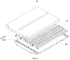
Fig. 6 is a schematic exploded diagram showing a configuration of a battery pack according to an embodiment of the present disclosure; and -
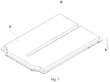
Fig. 7 is a schematic diagram showing a configuration of a battery pack according to a further embodiment of the present disclosure. - In the above drawings, the drawings are not drawn to scale.
- Reference numerals:
- 10, battery module;
- 11, secondary battery;
- 12, case; 12a, receiving hole; 121, first side wall; 122, second side wall; 123, bottom wall; 13, electrode assembly;
- 14, electrode unit; 14a, wide side; 14b, narrow side; 141, first electrode plate; 142, second electrode plate; 143, separator;
- 15, cap assembly; 151, cap plate; 152, electrode terminal;
- 16, first gap;
- 17, second gap;
- 18, third gap;
- 19, first end plate;
- 20, second end plate;
- 30, battery module;
- 31, housing; 31a, receiving chamber; 311, upper cover; 312, lower case;
- X, first direction; Y, second direction.
- Below, embodiments of the present disclosure will be further described in detail with reference to the drawings and embodiments. The detailed description of the embodiments and the accompanying drawings are intended to exemplarily illustrate the principles of the present disclosure and are not intended to limit the scope of the present disclosure. That is, the present disclosure is not limited to the described embodiments.
- In the description of the present disclosure, it should be noted that, unless otherwise stated, the meaning of "a plurality" is two or more; the orientation or positional relationship indicated by the terms "upper", "lower", "left", "right", "inner", "outer" and the like is merely for the purpose of describing the present disclosure and simplifying the description, and is not intended to indicate or imply that the device or component referred to has a particular orientation, is constructed and operated in a particular orientation, and therefore cannot be understood to be a limitation of the present disclosure. Moreover, the terms "first", "second", "third", "fourth" and the like are used for descriptive purposes only and are not to be construed as indicating or implying relative importance.
- In the description of the present disclosure, it should be noted that, unless otherwise stated, the terms "installation", "connected, and "coupled" are to be understood broadly, and may be, for example, a fixed connection, a disassemble connection, or an integral connection; they can be connected directly or indirectly through an intermediate medium. The specific meaning of the above terms in the present disclosure can be understood by the person skilled in the art according to actual circumstance.
- For better understanding the present disclosure, a
battery module 10 according to the embodiments of the present disclosure will be described in detail below by reference toFig. 1 to Fig. 7 . - As shown in
Fig. 1 , the embodiments of the present disclosure provide abattery module 10, comprising two or moresecondary batteries 11 according to the present embodiment and busbars, each of which is used for connecting twosecondary batteries 11. The two or moresecondary batteries 11 are arranged side by side in a first direction X, wherein the first direction X is an arrangement direction of the two or moresecondary batteries 11. One end of the busbar is fixedly connected to one of the twosecondary batteries 11, and the other end of the busbar is fixedly connected to the other one of the twosecondary batteries 11. In one embodiment, thesecondary battery 11 may be a battery of hard case or soft package. - Referring to
Fig. 2 , thesecondary battery 11 according to an embodiment of the present disclosure includes a case 12, anelectrode assembly 13 disposed in the case 12, and a closing portion sealingly connected with the case 12. - The case 12 of the present embodiment may be formed in a shape of a quadrangular prism or other shapes. The case 12 has an internal space for accommodating the
electrode assembly 13 and an electrolyte therein. The case 12 can be made of a material such as aluminum, aluminum alloy and plastic. - Referring to
Fig. 3 , theelectrode assembly 13 of the present embodiment includes two ormore electrode units 14. Theelectrode unit 14 of the present embodiment can be formed by stacking or winding afirst electrode plate 141, asecond electrode plate 142 and aseparator 143, and be formed to have a body portion and a tab connected with the body portion. Theseparator 143 is an insulator interposed between thefirst electrode plate 141 and thesecond electrode plate 142. Theelectrode unit 14 of the present embodiment is formed by winding theseparator 143, thefirst electrode plate 141 and thesecond electrode plate 142, and is formed into a flat shape comprising multiple loops. In the present embodiment, the description is made by exemplarily taking thefirst electrode plate 141 as a positive electrode plate and taking thesecond electrode plate 142 as a negative electrode plate. In other embodiments, thefirst electrode plate 141 may be a negative electrode plate while thesecond electrode plate 142 is a positive electrode plate. Further, a positive active material is coated on a coating region of the positive electrode plate while a negative active material is coated on a coating region of the negative electrode plate. A plurality of uncoated regions extending from the body portion serve as the tab. Theelectrode unit 14 includes two tabs, a positive tab and a negative tab, wherein the positive tab is formed by stacking the plurality of uncoated regions extending from the coated region of the positive electrode plate, and the negative tab is formed by stacking the plurality of uncoated regions extending from the coated region of the negative electrode plate. During infiltration of the electrolyte in the production or later use of thesecondary battery 11, the active material layer included in theelectrode unit 14 of the present embodiment will expand, thereby causing theentire electrode unit 14 to expand. Alternatively, the electrode unit of the present embodiment has a capacity of 50 Ah to 300 Ah. - The closing portion of the present disclosure may be an aluminum plastic film formed of aluminum alloy, plastic, nylon, or the like, or may be a
cap assembly 15 made of a material such as metal. The closing portion of the present embodiment is thecap assembly 15, which includes acap plate 151 andelectrode terminals 152. All of thecap plate 151 and theelectrode terminals 152 are located on one side of theelectrode assembly 13 in a second direction Y. Thecap assembly 15 is sealingly connected to the case 12 by thecap plate 151. Theelectrode terminals 152 are disposed on thecap plate 151 and are electrically connected to theelectrode assembly 13. - The battery module of the present embodiment includes two or more
secondary batteries 11. The two or moresecondary batteries 11 are arranged side by side in the first direction X. Thesecondary battery 11 includes the case 12 with the receivinghole 12a, and theelectrode assembly 13 disposed in the receivinghole 12a, wherein the receivinghole 12a has the opening and extends in the second direction Y, that is, the second direction Y is parallel to an extending direction of the receivinghole 12a. Theelectrode assembly 13 includes two ormore electrode units 14, which are stacked in the second direction Y, wherein the second direction Y is parallel to the stacking direction of the two ormore electrode units 14. In the present embodiment, the second direction Y is perpendicular to the first direction X, and also is perpendicular to an extending direction of the opening of the receivinghole 12a and that of the closing portion. It can be easily understood that, in the present embodiment, the second direction Y may intersect with and be approximately perpendicular to the first direction X, and the second direction Y may intersect with and be approximately perpendicular to the extending direction of the opening of the receivinghole 12a and that of the closing portion. If theelectrode unit 14 of the present embodiment expands, theelectrode assembly 13 may generate a first expansion force in the first direction X and a second expansion force in the second direction Y. Since the plurality of theelectrode units 14 are stacked, the first expansion force is smaller than the second expansion force. Therefore, theelectrode assembly 13 will expand primarily in the second direction Y, and the primary expansion force of theelectrode assembly 13 is in the second direction Y. In contrast, in the first direction X, the first expansion force of theelectrode assembly 13 is small, and thus has a little affection on the case 12. In the case that the two or moresecondary batteries 11 of the present embodiment are arranged side by side in the first direction X, since the second expansion force generated by eachsecondary battery 11 due to the expansion thereof has a direction intersecting with the first direction X, that is, the second expansion force generated by eachsecondary battery 11 due to the expansion thereof is in the second direction Y, a large combined force will not be formed by superposition of the second expansion forces generated by the respectivesecondary batteries 11 in the first direction X. As such, when fixing thebattery module 10 including two or moresecondary batteries 11 of the present embodiment by using an external fixing member in the first direction X, requirements on rigidity and strength of the fixing member can be lowered, which is beneficial to reduce a volume or weight of the fixing member, and further increase an energy density and space utilization of thesecondary battery 11 and theentire battery module 10, and also is beneficial to improve cycle performance of the secondary battery. - In the present embodiment, the
electrode unit 14 includes awide side 14a and anarrow side 14b. Thewide side 14a is disposed opposite to the closing portion, which is not limited to the situation that thewide side 14a and a surface of the closing portion towards thewide side 14a are completely opposite to each other in a strict sense, and also includes the situation that the both are opposite to each other partially, and the situation that the both are opposite to each other with thewide side 14a being arched due to expansion and the surface of the closing portion towards thewide side 14a being flat. Thenarrow side 14b is located on one end of thewide side 14a in the first direction X, where thewide side 14a has two opposite ends in the first direction X, and onenarrow side 14b is connected to one end of thewide side 14a. Thewide side 14a has an area larger than that of thenarrow side 14b. Thus, the expansion force generated by thewide side 14a is larger than that generated by thenarrow side 14b, which can further reduce the expansion force of thesecondary battery 11 in the first direction X. Preferably, a ratio of the area of thenarrow side 14b to the area of thewide side 14a is in a range of 1/10-1/2. If the ratio is greater than 1/2, the area of thenarrow side 14b is too large, resulting in that the combined force of the first expansion forces is too large; if the ratio is less than 1/10, the area of thewide side 14a is too large in the case where the capacity of thesecondary battery 11 is constant, which leads to difficulties in the infiltration of the electrolyte. - The
electrode unit 14 of the present embodiment is preferably formed by winding thefirst electrode plate 141, asecond electrode plate 142 and aseparator 143. Theelectrode unit 14 of the present embodiment is formed into a flat shape. Theelectrode unit 14 includes two winding end faces opposite to each other and a winding axis perpendicular to the winding end faces. Referring toFig. 3 , theelectrode unit 14 includes awide side 14a and anarrow side 14b, wherein thenarrow side 14b at least partially includes an arc region, and there are twowide sides 14a and twonarrow sides 14b. The twowide sides 14a are disposed opposite to each other in the second direction Y, and each extends perpendicular to the second direction Y; and the twonarrow sides 14b are disposed opposite to each other in the first direction X and are respectively connected to two opposite ends of eachwide side 14a in the first direction. Thewide sides 14a and thenarrow sides 14b are alternately arranged around the winding axis of theelectrode unit 14. Adjacent twoelectrode units 14 are disposed with their respectivewide sides 14a being contact with each other. When theelectrode unit 14 of the present embodiment expands, both thewide side 14a and thenarrow side 14b expand. Thewide side 14a expand in the second direction Y, and has a larger expansion amount than thenarrow side 14b. In one example, thewide side 14a is in a flat shape while thenarrow side 14b is in an arc shape. - Referring to
Fig. 3 , theelectrode unit 14 formed by winding in the present embodiment has multiple layers of thefirst electrode plates 141 in a radial direction. Thefirst electrode plates 141 in adjacent two layers have afirst gap 16 corresponding to thenarrow side 14b, and have asecond gap 17 corresponding to thewide side 14a. Here, both a dimension L1 of thefirst gap 16 and a dimension L2 of thesecond gap 17 refer to a sum of gaps between theseparator 143 and thefirst electrode plate 141 and gaps between theseparator 143 and thesecond electrode plate 142. When the active material coated on thefirst electrode plate 141 or thesecond electrode plate 142 of theelectrode unit 14 expands, each layer of thefirst electrode plates 141 will displace in the radial direction of theelectrode unit 14 due to the expansion force. Both of thefirst gap 16 and thesecond gap 17 can absorb the displacement of each layer of thefirst electrode plates 141, which can effectively reduce an amount of expansion displacement of thenarrow side 14b and thewide side 14a of theelectrode unit 14, thereby effectively reducing the expansion force released by theentire electrode unit 14 in various directions. In one embodiment, the dimension L1 of thefirst gap 16 is greater than the dimension L2 of thesecond gap 17, so that thefirst gap 16 can absorb more expansion displacement of thefirst electrode plate 141 than thesecond gap 17. As a result, thenarrow side 14b of theelectrode unit 14 has a smaller amount of expansion displacement than thewide side 14a of theelectrode unit 14, and thus can reduce the accumulation of the expansion force in the first direction X to a greater extent. In one embodiment, thefirst gap 16 and thesecond gap 17 are defined by gaps between the same two layers of thefirst electrode plates 141. In one embodiment, thefirst gap 16 has the dimension L1 of 5 µm to 50 µm. If the dimension L1 of thefirst gap 16 is less than 5 µm, thenarrow side 14b of theelectrode unit 14 will contact the case 12 earlier when theelectrode unit 14 expands, resulting in that theelectrode unit 14 will receive a larger reaction force when it continues to expand after thenarrow side 14b has contacted the case 12. This will further cause the electrolyte in thefirst gap 16 to be squeezed out, thereby causing that the lithium ion cannot be normally transferred, which adversely affects service life of thesecondary battery 11. Meanwhile, since thenarrow side 14b of theelectrode unit 14 is restrained by the case 12, the expansion force will be transferred to thewide side 14a, thereby causing the expansion force to be accumulated too much in the second direction Y. If the dimension L1 of thefirst gap 16 is greater than 50 µm, thefirst gap 16 between the adjacent two layers of thefirst electrode plates 141 is too large, thereby causing that a transfer time of the lithium ion is too long, which will thus lead to a poor dynamic performance on thenarrow side 14b and easy occurrence of lithium plating. - The case 12 according to the present embodiment is preferably made of a material of metal. Referring to
Fig. 2 , the case 12 includes afirst side wall 121, asecond side wall 122 and abottom wall 123 connected to thefirst side wall 121 and thesecond side wall 122. Thecap assembly 15 is disposed opposite to thebottom wall 123 in the second direction Y. Thecap assembly 15 is sealingly connected to thefirst side wall 121 and thesecond side wall 122. Thefirst side wall 121 has an area larger than that of thesecond side wall 122, and also larger than that of thebottom wall 123. Adjacent twosecondary batteries 11 are disposed with thefirst side walls 121 opposite to each other. Referring toFig. 4 orFig. 5 , thenarrow side 14b is disposed corresponding to thefirst side wall 121. In some particular cases, thenarrow side 14b of theelectrode unit 14 may also expand, but with a small expansion amount, and thus, a compressive force exerted on thefirst side wall 121 by thenarrow side 14b is small. Therefore, a combined force of the expansion forces from the respectivesecondary batteries 11 in the first direction X is small. Further, since thefirst side wall 121 has a larger area, the deformation of thefirst side wall 121 can be reduced. Meanwhile, the larger the expansion amount of theelectrode unit 14, the less the dimension L1 of thefirst gap 16 and the dimension L2 of thesecond gap 17. During use, theelectrode unit 14 consumes its internal electrolyte, and thus it is necessary to continuously replenish the electrolyte from the outside. When theelectrode unit 14 expands, thefirst side wall 121 will restrain thenarrow side 14b, causing thefirst gap 16 to become smaller. This will cause that the electrolyte in the case 12 is difficult to be replenished to an interior of theelectrode unit 14 through thefirst gap 16, thereby adversely affecting the electrical performance of theelectrode unit 14. Moreover, when theelectrode unit 14 expands, thefirst electrode plate 141 or thesecond electrode plate 142 located at the outermost layer will be subjected to a relatively large tensile stress, and thus is easy to be broken. Thefirst side wall 121 of the present embodiment can restrain thenarrow side 14b and prevent a too much expansion of thenarrow side 14b, thereby effectively reducing a possibility of breakage of thefirst electrode plate 141 or thesecond electrode plate 142. In one embodiment, there are twofirst side walls 121 and twosecond side walls 122. Thefirst side walls 121 and thesecond side walls 122 are alternately arranged, forming a cylindrical member with a rectangular cross section. Thebottom wall 123 is formed into a plate of a rectangular shape, and is sealingly connected with thefirst side wall 121 and thesecond side wall 122. - In one embodiment, referring to
Fig. 5 , athird gap 18 is provided between thenarrow side 14b and thefirst side wall 121. Thethird gap 18 has a dimension L3 of 0.3 mm to 0.9 mm. If the dimension L3 of the third gap is less than 0.3 mm, thenarrow side 14b of theelectrode unit 14 will completely invade thethird gap 18, contact and exert a compressive force on thefirst side wall 121, even when thenarrow side 14b expands to a small extent. This will cause that a too large compressive force is exerted on thefirst side wall 121 by theelectrode unit 14 when thenarrow side 14b of theelectrode unit 14 reaches maximum expansion amount, thereby causing deformation of thefirst side wall 121 or even deformation of theentire battery module 10 in the first direction X. If the dimension L3 of thethird gap 18 is greater than 0.9 mm, thenarrow side 14b of theelectrode unit 14 cannot completely invade thethird gap 18 and contact thefirst side wall 121 until it expands to a relatively great extent, thereby causing that thefirst side wall 121 cannot effectively restrain theelectrode unit 14. This will further cause a too much expansion of thenarrow side 14b of theelectrode unit 14, thereby causing thefirst electrode plate 141 or thesecond electrode plate 142 at the outermost layer to be broken. - In one embodiment, each of the
first side wall 121 and thesecond side wall 122 has a thickness less than a thickness M of thebottom wall 123. Since the main expansion direction of theelectrode unit 14 of the present embodiment is in the second direction Y, theelectrode unit 14 exerts a larger force on thebottom wall 123 than thefirst side wall 121 and thesecond side wall 122 when theelectrode unit 14 expands. Increasing the thickness M of thebottom wall 123 can enhance a strength of thebottom wall 123, increase the constraint on theelectrode unit 14, and improve deformation resistance of thebottom wall 123. In the embodiment in which thewide side 14a of theelectrode unit 14 faces thebottom wall 123, thebottom wall 123 can restrain the expansion of theelectrode unit 14, so that theelectrode unit 14 cannot expand too much. As a result, thefirst gap 16 will not be completely invaded and disappear, thereby ensuring sufficient electrolyte in thefirst gap 16. Further, reducing the thickness of thefirst side wall 121 and that of thesecond side wall 122 is beneficial to reduce a weight of the entiresecondary battery 11 and thereby conducive to improving the energy density of thesecondary battery 11 and thebattery module 10. - Referring to
Fig. 1 , thebattery module 10 of the present embodiment further includes afirst end plate 19 and asecond end plate 20, which are spaced apart from each other in the first direction X. Two or moresecondary batteries 11 are disposed between thefirst end plate 19 and thesecond end plate 20. Thefirst end plate 19 and thesecond end plate 20 each has a Young's modulus less than 30 GPa. Since the expansion force of eachsecondary battery 11 included in thebattery module 10 of the present embodiment is small in the first direction X, thefirst end plate 19 and thesecond end plate 20 each can have a smaller thickness in the first direction X, and the rigidity and strength requirements on thefirst end plate 19 and thesecond plate 20 also can be lowered, which is beneficial to reduce weights of thefirst end plate 19 and thesecond end plate 20, and also is beneficial to improve the energy density of thesecondary battery 11 and thebattery module 10. Moreover, limits on materials of thefirst end plate 19 and thesecond end plate 20 also can be reduced, and the materials of thefirst end plate 19 and thesecond end plate 20 can be selected from a wider range, which can reduce manufacturing difficulties and costs. In one embodiment, thebattery module 10 further includes a connecting member that is connected to both of thefirst end plate 19 and thesecond end plate 20. The connecting member can fasten thefirst end plate 19 and thesecond end plate 20, thereby fastening the respectivesecondary batteries 11, and improving positional stability of the respectivesecondary batteries 11. - The
battery module 10 according to the embodiments of the present disclosure includes two or moresecondary batteries 11 arranged side by side in the first direction X. Theelectrode units 14 included in the respectivesecondary batteries 11 are stacked in the second direction Y. When theelectrode unit 14 of the present embodiment expands, it mainly expands and deforms in the second direction Y, while with a small expansion amount in the first direction X. Thus, the combined expansion force in the first direction X of the expansion forces of the respectivesecondary batteries 11 is small. In the first direction X, thebattery module 10 does not need a structural member with high strength to restrain and offset the expansion force, or merely needs a structural member with low strength to restrain and offset the expansion force, which can effectively reduce a mass of the entire thebattery module 10, make thebattery module 10 to be more compact and effectively increase the energy density of thebattery module 10. Meanwhile, since thebattery module 10 has a small expansion amount in the first direction X, safety of the battery module during use can be effectively improved. - Referring to
Fig. 6 andFig. 7 , an embodiment of the present disclose further provides abattery pack 30. Thebattery pack 30 can be applied to a vehicle such as an automobile. The automobile has a receiving housing for accommodating thebattery pack 30, and the receiving housing is generally located at the bottom of the automobile. Since a chassis of the automobile is close to the ground and a height of the receiving housing determines a height space of the automobile, it is necessary to lengthen the receiving housing in a longitudinal direction or a width direction of the automobile, to reduce the height space of the automobile, which means lengths of thebattery pack 30 and thebattery module 10 are correspondingly lengthened, and the expansion force in the length direction will increase correspondingly. Therefore, it is required that thebattery pack 30 not only can reduce an occupation space in the height direction of the automobile, but also can have an expansion force not too large in the length direction of itself. The height direction of the automobile is parallel to the second direction Y, and one of the longitudinal direction or the width direction of the automobile is the same as the first direction X. - The
battery pack 30 of the present embodiment includes ahousing 31 and thebattery module 10 of the above embodiments disposed in thehousing 31. There may be onebattery module 10, or two ormore battery modules 10. - The
housing 31 of the present embodiment has a receivingchamber 31a for accommodating thebattery module 10. In one embodiment, thehousing 31 includes anupper cover 311 and a lower case 312, which can be sealingly connected to each other to seal thebattery module 10 within the receivingchamber 31a. Thebattery module 10 accommodated in the receivingchamber 31a can be fixedly connected to the lower case 312. - In one embodiment, the
housing 31 has a first height N greater than a second height H of thesecondary battery 11 and less than twice of the second height H of thesecondary battery 11, wherein the height of thehousing 31 is in the same direction as the second direction Y. In this case, a gap is reserved between thehousing 31 and the respectivesecondary batteries 11 of thebattery module 10. When theelectrode unit 14 expands too much and exerts a too large force to thecap assembly 15, the gap can provide a space for thecap assembly 15 so that thecap assembly 15 can be disconnected from the case 12, which can reduce a possibility of an explosion of thesecondary battery 11 that expands too much while cannot be relieved. - In one embodiment, the
battery pack 30 includes two to sixbattery modules 10 arranged in a width direction of thehousing 31. Each of thebattery modules 10 includes 20 to 32secondary batteries 11. In the present embodiment, the width direction of thehousing 31 is perpendicular to the first direction X and the second direction Y, and a length direction of thehousing 31 is the same as the first direction X. Since thesecondary battery 11 of the present embodiment has a small expansion amount in the first direction X, moresecondary batteries 11 can be arranged side by side in the first direction X, thereby greatly increasing the energy density of thebattery module 10. - In one embodiment, the
secondary battery 11 has a thickness D (as shown inFig. 2 ) of 50 mm or more, and a height H (as shown inFig. 4 ) of 80 mm or more. The thickness of thesecondary battery 11 has a same direction as the first direction X, and the height of thesecondary battery 11 has a same direction as the second direction Y. - The
battery pack 30 of the present embodiment includes ahousing 31 and abattery module 10. When expanding, thebattery module 10 has a small expansion amount in the length direction of thehousing 31, and thus will release a small expansion force in the length direction, and exert a small force on thehousing 31. As a result, in the first direction X, it is not necessary to use a structural member with high strength to restrain thebattery module 10, which is advantageous for reducing a volume and weight of the structural member, thereby facilitating lightweight design of thebattery pack 30 and improving the energy density of thebattery pack 30. Meanwhile, it is not necessary for thehousing 31 to have a high rigidity and strength in the first direction X, thereby lowering structural requirements on thehousing 31. - Although the present disclosure has been described with reference to the preferred embodiments, various modifications may be made to the present disclosure and components may be replaced with equivalents without departing from the scope of the present disclosure. In particular, the technical features mentioned in the various embodiments can be combined in any manner as long as there is no structural conflict. The present disclosure is not limited to the specific embodiments disclosed herein, but includes all technical solutions falling within the scope of the claims.
Claims (13)
- A battery module (10), comprising:two or more secondary batteries (11) arranged side by side in a first direction (X), each of which includes a case (12), an electrode assembly (13) and a closing portion, wherein the case (12) has a receiving hole (12a) comprising an opening and extending in a second direction (Y), and the first direction (X) intersects with the second direction (Y), wherein the closing portion is sealingly connected with the case (12) to close the opening, the electrode assembly (13) is disposed in the receiving hole (12a) and includes two or more electrode units (14), the electrode unit (14) includes a first electrode plate (141), a second electrode plate (142) and a separator (143), and the two or more electrode units (14) are stacked in the second direction (Y), characterized in that,the electrode unit (14) is formed by winding the first electrode plate (141), the second electrode plate (142) and the separator (143), and the electrode unit (14) is formed into a flat shape and has two wide sides (14a) and two narrow sides (14b), wherein the two narrow sides (14b) are connected to two opposite ends of the wide side (14a) in the first direction (X) respectively, the wide side (14a) is disposed opposite to the closing portion, and the wide side (14a) has an area larger than that of the narrow side (14b); andthe case (12) comprises a first side wall (121), a second side wall (122) and a bottom wall (123) connected to the first side wall (121) and the second side wall (122), wherein the first side wall (121) has a larger area than the second side wall (122) and the bottom wall (123), adjacent two secondary batteries (11) are disposed with the first side walls (121) not the second side walls (122) opposite to each other, and the narrow side (14b) of the electrode unit (14) is disposed corresponding to the first side wall (121).
- The battery module (10) of claim 1, characterized in that, a ratio of the area of the narrow side (14b) to that of the wide side (14a) is in a range of 1/10 ∼1/2.
- The battery module (10) of claim 1, characterized in that, the first electrode plates (141) in adjacent two layers have a first gap (16) corresponding to the narrow side (14b), and the first gap (16) has a dimension (L1) of 5 µm to 50 µm.
- The battery module (10) of claim 1, characterized in that, the first electrode plates (141) in adjacent two layers have a first gap (16) corresponding to the narrow side (14b) and a second gap (17) corresponding to the wide side (14a), wherein the first gap (16) has a dimension greater than that of the second gap (17).
- The battery module (10) of any of claims 1-4, characterized in that, the case (12) is made of a material of metal.
- The battery module (10) of claim 5, characterized in that, a third gap (18) is provided between the narrow side (14b) and the first side wall (121), and the third gap (18) has a dimension (L3) of 0.3 mm to 0.9 mm.
- The battery module (10) of claim 5 or 6, characterized in that, the first side wall (121) and the second side wall (122) each has a thickness less than that of the bottom wall (123).
- The battery module (10) of any of claims 1 to 7, characterized in that, the closing portion includes a cap plate (151) and electrode terminals (152), all of which are located at one side of the electrode assembly (13) in the second direction (Y), wherein the cap plate (151) is connected to the case (12), and the electrode terminals (152) are disposed on the cap plate (151) and electrically connected to the electrode assembly (13).
- The battery module (10) of any of claims 1 to 8, characterized in that, the battery module (10) further comprises a first end plate (19) and a second end plate (20) spaced apart from each other in the first direction (X), wherein the two or more secondary batteries (11) are disposed between the first end plate (19) and the second end plate (20), and the first end plate (19) and the second end plate (20) each has a Young's modulus less than 30 Gpa.
- A battery pack (30), comprising:a housing (31) having a receiving chamber (31a); andthe battery module (10) according to any of claims 1 to 9, wherein the battery module (10) is accommodated in the receiving chamber (31a).
- The battery pack (30) of claim 10, characterized in that, in the second direction (Y), the housing (31) has a first height (N) greater than a second height (H) of the secondary battery (11) and less than twice of the second height (H) of the secondary battery (11).
- The battery pack (30) of claim 10 or 11, characterized in that, the battery pack (30) comprises two to six battery modules (10) arranged in a width direction of the housing (31), and each of the battery modules (10) comprises 20 to 32 secondary batteries (11).
- The battery pack (30) of any of claims 10-12, characterized in that, the secondary battery (11) has a thickness (D) of 50 mm or more, and the secondary battery has a height (H) of 80 mm or more.
Priority Applications (1)
| Application Number | Priority Date | Filing Date | Title |
|---|---|---|---|
| PL19180572T PL3686948T3 (en) | 2018-12-29 | 2019-06-17 | Battery module and battery pack |
Applications Claiming Priority (1)
| Application Number | Priority Date | Filing Date | Title |
|---|---|---|---|
| CN201811646277.6A CN111384332B (en) | 2018-12-29 | 2018-12-29 | Battery modules and battery packs |
Publications (2)
| Publication Number | Publication Date |
|---|---|
| EP3686948A1 EP3686948A1 (en) | 2020-07-29 |
| EP3686948B1 true EP3686948B1 (en) | 2021-11-03 |
Family
ID=66912716
Family Applications (1)
| Application Number | Title | Priority Date | Filing Date |
|---|---|---|---|
| EP19180572.0A Active EP3686948B1 (en) | 2018-12-29 | 2019-06-17 | Battery module and battery pack |
Country Status (5)
| Country | Link |
|---|---|
| US (1) | US11139540B2 (en) |
| EP (1) | EP3686948B1 (en) |
| CN (1) | CN111384332B (en) |
| PL (1) | PL3686948T3 (en) |
| WO (1) | WO2020134747A1 (en) |
Families Citing this family (6)
| Publication number | Priority date | Publication date | Assignee | Title |
|---|---|---|---|---|
| CN111463367B (en) * | 2019-01-22 | 2024-09-06 | 宁德时代新能源科技股份有限公司 | Secondary battery and battery module |
| JP7208200B2 (en) * | 2020-09-09 | 2023-01-18 | プライムプラネットエナジー&ソリューションズ株式会社 | A battery, a battery case provided for the battery, and a battery case member for constructing the battery case |
| CN113654741B (en) * | 2021-08-27 | 2024-02-09 | 浙江机电职业技术学院 | Automatic monitoring and early warning system and monitoring method for tightness of power battery pack |
| CN115832561B (en) * | 2021-12-23 | 2025-02-18 | 宁德时代新能源科技股份有限公司 | Batteries and electrical devices |
| CN116325323B (en) * | 2022-01-12 | 2025-09-26 | 宁德时代新能源科技股份有限公司 | Battery, electrical device, method and device for preparing battery |
| JP2024014075A (en) * | 2022-07-21 | 2024-02-01 | プライムプラネットエナジー&ソリューションズ株式会社 | Energy storage module |
Family Cites Families (27)
| Publication number | Priority date | Publication date | Assignee | Title |
|---|---|---|---|---|
| ES2193849B1 (en) * | 2001-07-31 | 2005-03-01 | S.E. Acumulador Tudor, S.A. | BATTERY OF ELECTRIC ACCUMULATORS. |
| CN101467282A (en) * | 2005-10-03 | 2009-06-24 | Tdk兰达株式会社 | Battery pack |
| EP2223362B1 (en) * | 2007-10-19 | 2024-02-07 | Energizer Brands, LLC | Lithium-iron disulfide cell design |
| CN101626065A (en) * | 2008-07-11 | 2010-01-13 | 比亚迪股份有限公司 | Battery case and battery thereof |
| KR101222369B1 (en) * | 2011-01-05 | 2013-01-15 | 로베르트 보쉬 게엠베하 | Battery and battery pack comprising the same |
| DE102011078984A1 (en) | 2011-07-12 | 2013-01-17 | Bayerische Motoren Werke Aktiengesellschaft | High voltage storage unit i.e. battery, for supplying power to drive of motor car, has contact elements arranged on inner side of lid such that electrical interconnection between modules is separable during opening of lid |
| CN103094500A (en) | 2011-10-31 | 2013-05-08 | 浙江南都电源动力股份有限公司 | Shell system, battery and battery support having improved laminate |
| KR20140137180A (en) * | 2013-05-22 | 2014-12-02 | 삼성에스디아이 주식회사 | Rechargeable battery |
| DE112015005478T5 (en) | 2014-12-03 | 2017-08-24 | Kabushiki Kaisha Toyota Jidoshokki | ENERGY STORAGE DEVICE |
| KR101776898B1 (en) | 2014-12-24 | 2017-09-08 | 주식회사 엘지화학 | Battery Module |
| JP2016152203A (en) * | 2015-02-19 | 2016-08-22 | 日立オートモティブシステムズ株式会社 | Battery pack |
| KR102415884B1 (en) | 2015-11-02 | 2022-07-04 | 에스케이온 주식회사 | Secondary battery |
| CN105609882B (en) | 2016-03-18 | 2024-06-04 | 东莞烯谷新能源科技有限公司 | Internal multi-core stack energy storage device |
| US11289746B2 (en) | 2016-05-03 | 2022-03-29 | Bosch Battery Systems Llc | Cooling arrangement for an energy storage device |
| CN105957991B (en) | 2016-07-12 | 2018-12-04 | 宁德时代新能源科技股份有限公司 | Battery module |
| CN206490120U (en) | 2017-02-28 | 2017-09-12 | 宁德时代新能源科技股份有限公司 | Battery modules |
| CN207183466U (en) | 2017-09-19 | 2018-04-03 | 宁德时代新能源科技股份有限公司 | Heat exchange device and battery module |
| CN107919443A (en) | 2017-12-12 | 2018-04-17 | 江苏双登富朗特新能源有限公司 | The battery of the external sheath of coiled lithium ion battery |
| CN108198989B (en) | 2018-01-16 | 2021-01-12 | 宁德时代新能源科技股份有限公司 | Connecting member and rechargeable battery |
| CN108428921A (en) * | 2018-02-01 | 2018-08-21 | 宁德时代新能源科技股份有限公司 | Secondary battery |
| CN208173635U (en) * | 2018-04-20 | 2018-11-30 | 宁德时代新能源科技股份有限公司 | Secondary cell and battery modules |
| CN209298235U (en) | 2018-12-29 | 2019-08-23 | 宁德时代新能源科技股份有限公司 | Secondary battery and battery module |
| CN209217103U (en) | 2018-12-29 | 2019-08-06 | 宁德时代新能源科技股份有限公司 | Secondary battery and battery module |
| CN209217068U (en) * | 2018-12-29 | 2019-08-06 | 宁德时代新能源科技股份有限公司 | Battery modules and battery packs |
| CN209217104U (en) | 2018-12-29 | 2019-08-06 | 宁德时代新能源科技股份有限公司 | Secondary battery and battery module |
| CN209232866U (en) | 2018-12-29 | 2019-08-09 | 宁德时代新能源科技股份有限公司 | Secondary battery and battery module |
| CN209571433U (en) | 2019-01-22 | 2019-11-01 | 宁德时代新能源科技股份有限公司 | Secondary battery and battery module |
-
2018
- 2018-12-29 CN CN201811646277.6A patent/CN111384332B/en active Active
-
2019
- 2019-06-11 US US16/437,932 patent/US11139540B2/en active Active
- 2019-06-17 PL PL19180572T patent/PL3686948T3/en unknown
- 2019-06-17 EP EP19180572.0A patent/EP3686948B1/en active Active
- 2019-11-21 WO PCT/CN2019/119941 patent/WO2020134747A1/en not_active Ceased
Also Published As
| Publication number | Publication date |
|---|---|
| EP3686948A1 (en) | 2020-07-29 |
| US20200212412A1 (en) | 2020-07-02 |
| CN111384332A (en) | 2020-07-07 |
| CN111384332B (en) | 2024-10-01 |
| PL3686948T3 (en) | 2022-01-31 |
| US11139540B2 (en) | 2021-10-05 |
| WO2020134747A1 (en) | 2020-07-02 |
Similar Documents
| Publication | Publication Date | Title |
|---|---|---|
| EP3686948B1 (en) | Battery module and battery pack | |
| EP3800686B1 (en) | Secondary battery and battery module | |
| US11251493B2 (en) | Battery pack | |
| EP3883033B1 (en) | Secondary battery and battery module | |
| CN209217069U (en) | Secondary battery and battery module | |
| CN209217068U (en) | Battery modules and battery packs | |
| WO2023000511A1 (en) | Battery module, battery, electrical device, method and device for manufacturing battery | |
| EP2677587A1 (en) | Secondary battery | |
| EP4261992B1 (en) | Battery module case and battery module comprising the same | |
| US12212013B2 (en) | Battery, electric apparatus, and method and apparatus for manufacturing battery | |
| US12087957B2 (en) | Battery, apparatus using battery, and preparation method and preparation device of battery | |
| EP3869608B1 (en) | Battery module and battery pack | |
| US20250364663A1 (en) | Battery, and electrical device | |
| JP7161672B2 (en) | assembled battery | |
| EP3675202B1 (en) | Secondary battery and battery module | |
| CN115051121A (en) | Battery with a battery cell | |
| US20260106258A1 (en) | Battery module and battery pack including the same | |
| EP4618249A1 (en) | Battery module | |
| US20240322302A1 (en) | Battery cell, battery, electric apparatus, and preparation method and apparatus of battery cell | |
| CN218887363U (en) | Battery case and large capacity battery | |
| EP4664646A1 (en) | Battery assembly | |
| KR20250123320A (en) | Battery pack | |
| KR20250123592A (en) | Busbar assembly, cell assembly including the same and cell group including the same |
Legal Events
| Date | Code | Title | Description |
|---|---|---|---|
| PUAI | Public reference made under article 153(3) epc to a published international application that has entered the european phase |
Free format text: ORIGINAL CODE: 0009012 |
|
| STAA | Information on the status of an ep patent application or granted ep patent |
Free format text: STATUS: THE APPLICATION HAS BEEN PUBLISHED |
|
| AK | Designated contracting states |
Kind code of ref document: A1 Designated state(s): AL AT BE BG CH CY CZ DE DK EE ES FI FR GB GR HR HU IE IS IT LI LT LU LV MC MK MT NL NO PL PT RO RS SE SI SK SM TR |
|
| AX | Request for extension of the european patent |
Extension state: BA ME |
|
| STAA | Information on the status of an ep patent application or granted ep patent |
Free format text: STATUS: REQUEST FOR EXAMINATION WAS MADE |
|
| 17P | Request for examination filed |
Effective date: 20210126 |
|
| RBV | Designated contracting states (corrected) |
Designated state(s): AL AT BE BG CH CY CZ DE DK EE ES FI FR GB GR HR HU IE IS IT LI LT LU LV MC MK MT NL NO PL PT RO RS SE SI SK SM TR |
|
| REG | Reference to a national code |
Ref country code: DE Ref legal event code: R079 Ref document number: 602019008859 Country of ref document: DE Free format text: PREVIOUS MAIN CLASS: H01M0002020000 Ipc: H01M0010040000 |
|
| GRAP | Despatch of communication of intention to grant a patent |
Free format text: ORIGINAL CODE: EPIDOSNIGR1 |
|
| STAA | Information on the status of an ep patent application or granted ep patent |
Free format text: STATUS: GRANT OF PATENT IS INTENDED |
|
| RIC1 | Information provided on ipc code assigned before grant |
Ipc: H01M 10/04 20060101AFI20210623BHEP Ipc: H01M 50/103 20210101ALI20210623BHEP Ipc: H01M 50/119 20210101ALI20210623BHEP Ipc: H01M 50/209 20210101ALI20210623BHEP |
|
| INTG | Intention to grant announced |
Effective date: 20210715 |
|
| GRAS | Grant fee paid |
Free format text: ORIGINAL CODE: EPIDOSNIGR3 |
|
| GRAA | (expected) grant |
Free format text: ORIGINAL CODE: 0009210 |
|
| STAA | Information on the status of an ep patent application or granted ep patent |
Free format text: STATUS: THE PATENT HAS BEEN GRANTED |
|
| AK | Designated contracting states |
Kind code of ref document: B1 Designated state(s): AL AT BE BG CH CY CZ DE DK EE ES FI FR GB GR HR HU IE IS IT LI LT LU LV MC MK MT NL NO PL PT RO RS SE SI SK SM TR |
|
| REG | Reference to a national code |
Ref country code: GB Ref legal event code: FG4D |
|
| REG | Reference to a national code |
Ref country code: AT Ref legal event code: REF Ref document number: 1444794 Country of ref document: AT Kind code of ref document: T Effective date: 20211115 Ref country code: CH Ref legal event code: EP |
|
| REG | Reference to a national code |
Ref country code: DE Ref legal event code: R096 Ref document number: 602019008859 Country of ref document: DE |
|
| REG | Reference to a national code |
Ref country code: IE Ref legal event code: FG4D |
|
| REG | Reference to a national code |
Ref country code: SE Ref legal event code: TRGR |
|
| REG | Reference to a national code |
Ref country code: NL Ref legal event code: FP |
|
| REG | Reference to a national code |
Ref country code: LT Ref legal event code: MG9D |
|
| REG | Reference to a national code |
Ref country code: AT Ref legal event code: MK05 Ref document number: 1444794 Country of ref document: AT Kind code of ref document: T Effective date: 20211103 |
|
| PG25 | Lapsed in a contracting state [announced via postgrant information from national office to epo] |
Ref country code: RS Free format text: LAPSE BECAUSE OF FAILURE TO SUBMIT A TRANSLATION OF THE DESCRIPTION OR TO PAY THE FEE WITHIN THE PRESCRIBED TIME-LIMIT Effective date: 20211103 Ref country code: LT Free format text: LAPSE BECAUSE OF FAILURE TO SUBMIT A TRANSLATION OF THE DESCRIPTION OR TO PAY THE FEE WITHIN THE PRESCRIBED TIME-LIMIT Effective date: 20211103 Ref country code: FI Free format text: LAPSE BECAUSE OF FAILURE TO SUBMIT A TRANSLATION OF THE DESCRIPTION OR TO PAY THE FEE WITHIN THE PRESCRIBED TIME-LIMIT Effective date: 20211103 Ref country code: BG Free format text: LAPSE BECAUSE OF FAILURE TO SUBMIT A TRANSLATION OF THE DESCRIPTION OR TO PAY THE FEE WITHIN THE PRESCRIBED TIME-LIMIT Effective date: 20220203 Ref country code: AT Free format text: LAPSE BECAUSE OF FAILURE TO SUBMIT A TRANSLATION OF THE DESCRIPTION OR TO PAY THE FEE WITHIN THE PRESCRIBED TIME-LIMIT Effective date: 20211103 |
|
| PG25 | Lapsed in a contracting state [announced via postgrant information from national office to epo] |
Ref country code: IS Free format text: LAPSE BECAUSE OF FAILURE TO SUBMIT A TRANSLATION OF THE DESCRIPTION OR TO PAY THE FEE WITHIN THE PRESCRIBED TIME-LIMIT Effective date: 20220303 Ref country code: PT Free format text: LAPSE BECAUSE OF FAILURE TO SUBMIT A TRANSLATION OF THE DESCRIPTION OR TO PAY THE FEE WITHIN THE PRESCRIBED TIME-LIMIT Effective date: 20220303 Ref country code: NO Free format text: LAPSE BECAUSE OF FAILURE TO SUBMIT A TRANSLATION OF THE DESCRIPTION OR TO PAY THE FEE WITHIN THE PRESCRIBED TIME-LIMIT Effective date: 20220203 Ref country code: LV Free format text: LAPSE BECAUSE OF FAILURE TO SUBMIT A TRANSLATION OF THE DESCRIPTION OR TO PAY THE FEE WITHIN THE PRESCRIBED TIME-LIMIT Effective date: 20211103 Ref country code: HR Free format text: LAPSE BECAUSE OF FAILURE TO SUBMIT A TRANSLATION OF THE DESCRIPTION OR TO PAY THE FEE WITHIN THE PRESCRIBED TIME-LIMIT Effective date: 20211103 Ref country code: GR Free format text: LAPSE BECAUSE OF FAILURE TO SUBMIT A TRANSLATION OF THE DESCRIPTION OR TO PAY THE FEE WITHIN THE PRESCRIBED TIME-LIMIT Effective date: 20220204 Ref country code: ES Free format text: LAPSE BECAUSE OF FAILURE TO SUBMIT A TRANSLATION OF THE DESCRIPTION OR TO PAY THE FEE WITHIN THE PRESCRIBED TIME-LIMIT Effective date: 20211103 |
|
| PG25 | Lapsed in a contracting state [announced via postgrant information from national office to epo] |
Ref country code: SM Free format text: LAPSE BECAUSE OF FAILURE TO SUBMIT A TRANSLATION OF THE DESCRIPTION OR TO PAY THE FEE WITHIN THE PRESCRIBED TIME-LIMIT Effective date: 20211103 Ref country code: SK Free format text: LAPSE BECAUSE OF FAILURE TO SUBMIT A TRANSLATION OF THE DESCRIPTION OR TO PAY THE FEE WITHIN THE PRESCRIBED TIME-LIMIT Effective date: 20211103 Ref country code: RO Free format text: LAPSE BECAUSE OF FAILURE TO SUBMIT A TRANSLATION OF THE DESCRIPTION OR TO PAY THE FEE WITHIN THE PRESCRIBED TIME-LIMIT Effective date: 20211103 Ref country code: EE Free format text: LAPSE BECAUSE OF FAILURE TO SUBMIT A TRANSLATION OF THE DESCRIPTION OR TO PAY THE FEE WITHIN THE PRESCRIBED TIME-LIMIT Effective date: 20211103 Ref country code: DK Free format text: LAPSE BECAUSE OF FAILURE TO SUBMIT A TRANSLATION OF THE DESCRIPTION OR TO PAY THE FEE WITHIN THE PRESCRIBED TIME-LIMIT Effective date: 20211103 Ref country code: CZ Free format text: LAPSE BECAUSE OF FAILURE TO SUBMIT A TRANSLATION OF THE DESCRIPTION OR TO PAY THE FEE WITHIN THE PRESCRIBED TIME-LIMIT Effective date: 20211103 |
|
| REG | Reference to a national code |
Ref country code: DE Ref legal event code: R097 Ref document number: 602019008859 Country of ref document: DE |
|
| PLBE | No opposition filed within time limit |
Free format text: ORIGINAL CODE: 0009261 |
|
| STAA | Information on the status of an ep patent application or granted ep patent |
Free format text: STATUS: NO OPPOSITION FILED WITHIN TIME LIMIT |
|
| 26N | No opposition filed |
Effective date: 20220804 |
|
| PG25 | Lapsed in a contracting state [announced via postgrant information from national office to epo] |
Ref country code: AL Free format text: LAPSE BECAUSE OF FAILURE TO SUBMIT A TRANSLATION OF THE DESCRIPTION OR TO PAY THE FEE WITHIN THE PRESCRIBED TIME-LIMIT Effective date: 20211103 |
|
| PG25 | Lapsed in a contracting state [announced via postgrant information from national office to epo] |
Ref country code: SI Free format text: LAPSE BECAUSE OF FAILURE TO SUBMIT A TRANSLATION OF THE DESCRIPTION OR TO PAY THE FEE WITHIN THE PRESCRIBED TIME-LIMIT Effective date: 20211103 |
|
| PG25 | Lapsed in a contracting state [announced via postgrant information from national office to epo] |
Ref country code: MC Free format text: LAPSE BECAUSE OF FAILURE TO SUBMIT A TRANSLATION OF THE DESCRIPTION OR TO PAY THE FEE WITHIN THE PRESCRIBED TIME-LIMIT Effective date: 20211103 |
|
| REG | Reference to a national code |
Ref country code: CH Ref legal event code: PL |
|
| PG25 | Lapsed in a contracting state [announced via postgrant information from national office to epo] |
Ref country code: LU Free format text: LAPSE BECAUSE OF NON-PAYMENT OF DUE FEES Effective date: 20220617 Ref country code: LI Free format text: LAPSE BECAUSE OF NON-PAYMENT OF DUE FEES Effective date: 20220630 Ref country code: IE Free format text: LAPSE BECAUSE OF NON-PAYMENT OF DUE FEES Effective date: 20220617 Ref country code: CH Free format text: LAPSE BECAUSE OF NON-PAYMENT OF DUE FEES Effective date: 20220630 |
|
| P01 | Opt-out of the competence of the unified patent court (upc) registered |
Effective date: 20230516 |
|
| PG25 | Lapsed in a contracting state [announced via postgrant information from national office to epo] |
Ref country code: MK Free format text: LAPSE BECAUSE OF FAILURE TO SUBMIT A TRANSLATION OF THE DESCRIPTION OR TO PAY THE FEE WITHIN THE PRESCRIBED TIME-LIMIT Effective date: 20211103 Ref country code: CY Free format text: LAPSE BECAUSE OF FAILURE TO SUBMIT A TRANSLATION OF THE DESCRIPTION OR TO PAY THE FEE WITHIN THE PRESCRIBED TIME-LIMIT Effective date: 20211103 |
|
| PG25 | Lapsed in a contracting state [announced via postgrant information from national office to epo] |
Ref country code: HU Free format text: LAPSE BECAUSE OF FAILURE TO SUBMIT A TRANSLATION OF THE DESCRIPTION OR TO PAY THE FEE WITHIN THE PRESCRIBED TIME-LIMIT; INVALID AB INITIO Effective date: 20190617 |
|
| PG25 | Lapsed in a contracting state [announced via postgrant information from national office to epo] |
Ref country code: TR Free format text: LAPSE BECAUSE OF FAILURE TO SUBMIT A TRANSLATION OF THE DESCRIPTION OR TO PAY THE FEE WITHIN THE PRESCRIBED TIME-LIMIT Effective date: 20211103 |
|
| REG | Reference to a national code |
Ref country code: DE Ref legal event code: R081 Ref document number: 602019008859 Country of ref document: DE Owner name: CONTEMPORARY AMPEREX TECHNOLOGY (HONG KONG) LI, HK Free format text: FORMER OWNER: CONTEMPORARY AMPEREX TECHNOLOGY CO., LIMITED, NINGDE CITY, FUJIAN, CN |
|
| REG | Reference to a national code |
Ref country code: NL Ref legal event code: PD Owner name: CONTEMPORARY AMPEREX TECHNOLOGY (HONG KONG) LIMITED; CN Free format text: DETAILS ASSIGNMENT: CHANGE OF OWNER(S), ASSIGNMENT; FORMER OWNER NAME: CONTEMPORARY AMPEREX TECHNOLOGY CO., LIMITED Effective date: 20240819 |
|
| REG | Reference to a national code |
Ref country code: GB Ref legal event code: 732E Free format text: REGISTERED BETWEEN 20240808 AND 20240814 |
|
| PG25 | Lapsed in a contracting state [announced via postgrant information from national office to epo] |
Ref country code: MT Free format text: LAPSE BECAUSE OF FAILURE TO SUBMIT A TRANSLATION OF THE DESCRIPTION OR TO PAY THE FEE WITHIN THE PRESCRIBED TIME-LIMIT Effective date: 20211103 |
|
| REG | Reference to a national code |
Ref country code: BE Ref legal event code: PD Owner name: CONTEMPORARY AMPEREX TECHNOLOGY (HONG KONG) LIMITED; CN Free format text: DETAILS ASSIGNMENT: CHANGE OF OWNER(S), ASSIGNMENT; FORMER OWNER NAME: CONTEMPORARY AMPEREX TECHNOLOGY CO., LIMITED Effective date: 20240807 |
|
| PGFP | Annual fee paid to national office [announced via postgrant information from national office to epo] |
Ref country code: SE Payment date: 20250310 Year of fee payment: 7 |
|
| PGFP | Annual fee paid to national office [announced via postgrant information from national office to epo] |
Ref country code: NL Payment date: 20250409 Year of fee payment: 7 |
|
| PGFP | Annual fee paid to national office [announced via postgrant information from national office to epo] |
Ref country code: DE Payment date: 20250402 Year of fee payment: 7 |
|
| PGFP | Annual fee paid to national office [announced via postgrant information from national office to epo] |
Ref country code: GB Payment date: 20250401 Year of fee payment: 7 |
|
| PGFP | Annual fee paid to national office [announced via postgrant information from national office to epo] |
Ref country code: IT Payment date: 20250522 Year of fee payment: 7 Ref country code: BE Payment date: 20250410 Year of fee payment: 7 |
|
| PGFP | Annual fee paid to national office [announced via postgrant information from national office to epo] |
Ref country code: FR Payment date: 20250409 Year of fee payment: 7 |
|
| PGFP | Annual fee paid to national office [announced via postgrant information from national office to epo] |
Ref country code: PL Payment date: 20260327 Year of fee payment: 8 |