EP3686767B1 - Method, device and system for identifying a device - Google Patents
Method, device and system for identifying a device Download PDFInfo
- Publication number
- EP3686767B1 EP3686767B1 EP19305101.8A EP19305101A EP3686767B1 EP 3686767 B1 EP3686767 B1 EP 3686767B1 EP 19305101 A EP19305101 A EP 19305101A EP 3686767 B1 EP3686767 B1 EP 3686767B1
- Authority
- EP
- European Patent Office
- Prior art keywords
- head
- function
- mounted device
- data
- tag
- Prior art date
- Legal status (The legal status is an assumption and is not a legal conclusion. Google has not performed a legal analysis and makes no representation as to the accuracy of the status listed.)
- Active
Links
Images

Classifications
-
- H—ELECTRICITY
- H04—ELECTRIC COMMUNICATION TECHNIQUE
- H04W—WIRELESS COMMUNICATION NETWORKS
- H04W4/00—Services specially adapted for wireless communication networks; Facilities therefor
- H04W4/80—Services using short range communication, e.g. near-field communication [NFC], radio-frequency identification [RFID] or low energy communication
-
- G—PHYSICS
- G02—OPTICS
- G02C—SPECTACLES; SUNGLASSES OR GOGGLES INSOFAR AS THEY HAVE THE SAME FEATURES AS SPECTACLES; CONTACT LENSES
- G02C7/00—Optical parts
- G02C7/02—Lenses; Lens systems ; Methods of designing lenses
- G02C7/024—Methods of designing ophthalmic lenses
- G02C7/027—Methods of designing ophthalmic lenses considering wearer's parameters
-
- G—PHYSICS
- G06—COMPUTING OR CALCULATING; COUNTING
- G06K—GRAPHICAL DATA READING; PRESENTATION OF DATA; RECORD CARRIERS; HANDLING RECORD CARRIERS
- G06K7/00—Methods or arrangements for sensing record carriers, e.g. for reading patterns
- G06K7/10—Methods or arrangements for sensing record carriers, e.g. for reading patterns by electromagnetic radiation, e.g. optical sensing; by corpuscular radiation
- G06K7/10009—Methods or arrangements for sensing record carriers, e.g. for reading patterns by electromagnetic radiation, e.g. optical sensing; by corpuscular radiation sensing by radiation using wavelengths larger than 0.1 mm, e.g. radio-waves or microwaves
- G06K7/10366—Methods or arrangements for sensing record carriers, e.g. for reading patterns by electromagnetic radiation, e.g. optical sensing; by corpuscular radiation sensing by radiation using wavelengths larger than 0.1 mm, e.g. radio-waves or microwaves the interrogation device being adapted for miscellaneous applications
- G06K7/10376—Methods or arrangements for sensing record carriers, e.g. for reading patterns by electromagnetic radiation, e.g. optical sensing; by corpuscular radiation sensing by radiation using wavelengths larger than 0.1 mm, e.g. radio-waves or microwaves the interrogation device being adapted for miscellaneous applications the interrogation device being adapted for being moveable
- G06K7/10396—Methods or arrangements for sensing record carriers, e.g. for reading patterns by electromagnetic radiation, e.g. optical sensing; by corpuscular radiation sensing by radiation using wavelengths larger than 0.1 mm, e.g. radio-waves or microwaves the interrogation device being adapted for miscellaneous applications the interrogation device being adapted for being moveable the interrogation device being wearable, e.g. as a glove, bracelet, or ring
-
- G—PHYSICS
- G02—OPTICS
- G02B—OPTICAL ELEMENTS, SYSTEMS OR APPARATUS
- G02B27/00—Optical systems or apparatus not provided for by any of the groups G02B1/00 - G02B26/00, G02B30/00
- G02B27/01—Head-up displays
- G02B27/017—Head mounted
-
- G—PHYSICS
- G02—OPTICS
- G02C—SPECTACLES; SUNGLASSES OR GOGGLES INSOFAR AS THEY HAVE THE SAME FEATURES AS SPECTACLES; CONTACT LENSES
- G02C7/00—Optical parts
- G02C7/02—Lenses; Lens systems ; Methods of designing lenses
- G02C7/024—Methods of designing ophthalmic lenses
- G02C7/028—Special mathematical design techniques
-
- G—PHYSICS
- G02—OPTICS
- G02C—SPECTACLES; SUNGLASSES OR GOGGLES INSOFAR AS THEY HAVE THE SAME FEATURES AS SPECTACLES; CONTACT LENSES
- G02C7/00—Optical parts
- G02C7/02—Lenses; Lens systems ; Methods of designing lenses
- G02C7/06—Lenses; Lens systems ; Methods of designing lenses bifocal; multifocal ; progressive
- G02C7/061—Spectacle lenses with progressively varying focal power
-
- G—PHYSICS
- G02—OPTICS
- G02C—SPECTACLES; SUNGLASSES OR GOGGLES INSOFAR AS THEY HAVE THE SAME FEATURES AS SPECTACLES; CONTACT LENSES
- G02C7/00—Optical parts
- G02C7/02—Lenses; Lens systems ; Methods of designing lenses
- G02C7/08—Auxiliary lenses; Arrangements for varying focal length
- G02C7/081—Ophthalmic lenses with variable focal length
- G02C7/083—Electrooptic lenses
-
- G—PHYSICS
- G02—OPTICS
- G02C—SPECTACLES; SUNGLASSES OR GOGGLES INSOFAR AS THEY HAVE THE SAME FEATURES AS SPECTACLES; CONTACT LENSES
- G02C7/00—Optical parts
- G02C7/10—Filters, e.g. for facilitating adaptation of the eyes to the dark; Sunglasses
- G02C7/101—Filters, e.g. for facilitating adaptation of the eyes to the dark; Sunglasses having an electro-optical light valve
-
- G—PHYSICS
- G06—COMPUTING OR CALCULATING; COUNTING
- G06K—GRAPHICAL DATA READING; PRESENTATION OF DATA; RECORD CARRIERS; HANDLING RECORD CARRIERS
- G06K17/00—Methods or arrangements for effecting co-operative working between equipments covered by two or more of main groups G06K1/00 - G06K15/00, e.g. automatic card files incorporating conveying and reading operations
- G06K17/0022—Methods or arrangements for effecting co-operative working between equipments covered by two or more of main groups G06K1/00 - G06K15/00, e.g. automatic card files incorporating conveying and reading operations arrangements or provisions for transferring data to distant stations, e.g. from a sensing device
- G06K17/0029—Methods or arrangements for effecting co-operative working between equipments covered by two or more of main groups G06K1/00 - G06K15/00, e.g. automatic card files incorporating conveying and reading operations arrangements or provisions for transferring data to distant stations, e.g. from a sensing device the arrangement being specially adapted for wireless interrogation of grouped or bundled articles tagged with wireless record carriers
-
- G—PHYSICS
- G06—COMPUTING OR CALCULATING; COUNTING
- G06K—GRAPHICAL DATA READING; PRESENTATION OF DATA; RECORD CARRIERS; HANDLING RECORD CARRIERS
- G06K7/00—Methods or arrangements for sensing record carriers, e.g. for reading patterns
-
- G—PHYSICS
- G06—COMPUTING OR CALCULATING; COUNTING
- G06K—GRAPHICAL DATA READING; PRESENTATION OF DATA; RECORD CARRIERS; HANDLING RECORD CARRIERS
- G06K7/00—Methods or arrangements for sensing record carriers, e.g. for reading patterns
- G06K7/10—Methods or arrangements for sensing record carriers, e.g. for reading patterns by electromagnetic radiation, e.g. optical sensing; by corpuscular radiation
-
- G—PHYSICS
- G06—COMPUTING OR CALCULATING; COUNTING
- G06K—GRAPHICAL DATA READING; PRESENTATION OF DATA; RECORD CARRIERS; HANDLING RECORD CARRIERS
- G06K7/00—Methods or arrangements for sensing record carriers, e.g. for reading patterns
- G06K7/10—Methods or arrangements for sensing record carriers, e.g. for reading patterns by electromagnetic radiation, e.g. optical sensing; by corpuscular radiation
- G06K7/10009—Methods or arrangements for sensing record carriers, e.g. for reading patterns by electromagnetic radiation, e.g. optical sensing; by corpuscular radiation sensing by radiation using wavelengths larger than 0.1 mm, e.g. radio-waves or microwaves
- G06K7/10019—Methods or arrangements for sensing record carriers, e.g. for reading patterns by electromagnetic radiation, e.g. optical sensing; by corpuscular radiation sensing by radiation using wavelengths larger than 0.1 mm, e.g. radio-waves or microwaves resolving collision on the communication channels between simultaneously or concurrently interrogated record carriers.
- G06K7/10079—Methods or arrangements for sensing record carriers, e.g. for reading patterns by electromagnetic radiation, e.g. optical sensing; by corpuscular radiation sensing by radiation using wavelengths larger than 0.1 mm, e.g. radio-waves or microwaves resolving collision on the communication channels between simultaneously or concurrently interrogated record carriers. the collision being resolved in the spatial domain, e.g. temporary shields for blindfolding the interrogator in specific directions
- G06K7/10089—Methods or arrangements for sensing record carriers, e.g. for reading patterns by electromagnetic radiation, e.g. optical sensing; by corpuscular radiation sensing by radiation using wavelengths larger than 0.1 mm, e.g. radio-waves or microwaves resolving collision on the communication channels between simultaneously or concurrently interrogated record carriers. the collision being resolved in the spatial domain, e.g. temporary shields for blindfolding the interrogator in specific directions the interrogation device using at least one directional antenna or directional interrogation field to resolve the collision
- G06K7/10099—Methods or arrangements for sensing record carriers, e.g. for reading patterns by electromagnetic radiation, e.g. optical sensing; by corpuscular radiation sensing by radiation using wavelengths larger than 0.1 mm, e.g. radio-waves or microwaves resolving collision on the communication channels between simultaneously or concurrently interrogated record carriers. the collision being resolved in the spatial domain, e.g. temporary shields for blindfolding the interrogator in specific directions the interrogation device using at least one directional antenna or directional interrogation field to resolve the collision the directional field being used for pinpointing the location of the record carrier, e.g. for finding or locating an RFID tag amongst a plurality of RFID tags, each RFID tag being associated with an object, e.g. for physically locating the RFID tagged object in a warehouse
-
- G—PHYSICS
- G06—COMPUTING OR CALCULATING; COUNTING
- G06K—GRAPHICAL DATA READING; PRESENTATION OF DATA; RECORD CARRIERS; HANDLING RECORD CARRIERS
- G06K7/00—Methods or arrangements for sensing record carriers, e.g. for reading patterns
- G06K7/10—Methods or arrangements for sensing record carriers, e.g. for reading patterns by electromagnetic radiation, e.g. optical sensing; by corpuscular radiation
- G06K7/10009—Methods or arrangements for sensing record carriers, e.g. for reading patterns by electromagnetic radiation, e.g. optical sensing; by corpuscular radiation sensing by radiation using wavelengths larger than 0.1 mm, e.g. radio-waves or microwaves
- G06K7/10366—Methods or arrangements for sensing record carriers, e.g. for reading patterns by electromagnetic radiation, e.g. optical sensing; by corpuscular radiation sensing by radiation using wavelengths larger than 0.1 mm, e.g. radio-waves or microwaves the interrogation device being adapted for miscellaneous applications
- G06K7/10376—Methods or arrangements for sensing record carriers, e.g. for reading patterns by electromagnetic radiation, e.g. optical sensing; by corpuscular radiation sensing by radiation using wavelengths larger than 0.1 mm, e.g. radio-waves or microwaves the interrogation device being adapted for miscellaneous applications the interrogation device being adapted for being moveable
- G06K7/10386—Methods or arrangements for sensing record carriers, e.g. for reading patterns by electromagnetic radiation, e.g. optical sensing; by corpuscular radiation sensing by radiation using wavelengths larger than 0.1 mm, e.g. radio-waves or microwaves the interrogation device being adapted for miscellaneous applications the interrogation device being adapted for being moveable the interrogation device being of the portable or hand-handheld type, e.g. incorporated in ubiquitous hand-held devices such as PDA or mobile phone, or in the form of a portable dedicated RFID reader
-
- H—ELECTRICITY
- H04—ELECTRIC COMMUNICATION TECHNIQUE
- H04B—TRANSMISSION
- H04B1/00—Details of transmission systems, not covered by a single one of groups H04B3/00 - H04B13/00; Details of transmission systems not characterised by the medium used for transmission
- H04B1/38—Transceivers, i.e. devices in which transmitter and receiver form a structural unit and in which at least one part is used for functions of transmitting and receiving
- H04B1/3827—Portable transceivers
- H04B1/385—Transceivers carried on the body, e.g. in helmets
-
- H—ELECTRICITY
- H04—ELECTRIC COMMUNICATION TECHNIQUE
- H04B—TRANSMISSION
- H04B5/00—Near-field transmission systems, e.g. inductive or capacitive transmission systems
- H04B5/70—Near-field transmission systems, e.g. inductive or capacitive transmission systems specially adapted for specific purposes
- H04B5/77—Near-field transmission systems, e.g. inductive or capacitive transmission systems specially adapted for specific purposes for interrogation
-
- H—ELECTRICITY
- H04—ELECTRIC COMMUNICATION TECHNIQUE
- H04W—WIRELESS COMMUNICATION NETWORKS
- H04W4/00—Services specially adapted for wireless communication networks; Facilities therefor
- H04W4/02—Services making use of location information
- H04W4/023—Services making use of location information using mutual or relative location information between multiple location based services [LBS] targets or of distance thresholds
-
- G—PHYSICS
- G02—OPTICS
- G02B—OPTICAL ELEMENTS, SYSTEMS OR APPARATUS
- G02B27/00—Optical systems or apparatus not provided for by any of the groups G02B1/00 - G02B26/00, G02B30/00
- G02B27/01—Head-up displays
- G02B27/0101—Head-up displays characterised by optical features
- G02B2027/0138—Head-up displays characterised by optical features comprising image capture systems, e.g. camera
-
- G—PHYSICS
- G02—OPTICS
- G02B—OPTICAL ELEMENTS, SYSTEMS OR APPARATUS
- G02B27/00—Optical systems or apparatus not provided for by any of the groups G02B1/00 - G02B26/00, G02B30/00
- G02B27/01—Head-up displays
- G02B27/0101—Head-up displays characterised by optical features
- G02B2027/014—Head-up displays characterised by optical features comprising information/image processing systems
-
- H—ELECTRICITY
- H04—ELECTRIC COMMUNICATION TECHNIQUE
- H04B—TRANSMISSION
- H04B1/00—Details of transmission systems, not covered by a single one of groups H04B3/00 - H04B13/00; Details of transmission systems not characterised by the medium used for transmission
- H04B1/38—Transceivers, i.e. devices in which transmitter and receiver form a structural unit and in which at least one part is used for functions of transmitting and receiving
- H04B1/3827—Portable transceivers
- H04B1/385—Transceivers carried on the body, e.g. in helmets
- H04B2001/3866—Transceivers carried on the body, e.g. in helmets carried on the head
Definitions
- the invention relates to a method for identifying a distinct device within a given range of a head-mounted device.
- the invention relates to a head-mounted device comprising a processor adapted to carry the method of the invention, and to a system comprising said head-mounted device and at least an electronic wireless tag.
- Clouclip is selling a device allowing to detect the proximity of an electronic screen.
- such technology does not permit to identify an object within proximity.
- Other examples of devices are described in US 2008/191846 A1 , against which the independent claims are delimited, US 2018/167549 A1 , US 10149958 B1 and WO 2011/053442 A1 .
- the invention proposes a method for identifying a distinct device within a given range distance of the head-mounted device, the head-mounted device comprises receiving means adapted to receive wireless signals and a memory adapted to store data, a function controller adapted to control at least one function of the head-mounted device and at least a controllable active optical lens, the method comprising:
- the method according to the invention allows to accurately identify a device within a predefined range of the head-mounted device.
- Another object of the invention relates to a head-mounted device comprising:
- the invention further relates to a system comprising:
- the invention relates to a method implemented with a head-mounted device for identifying a distinct device within a given range distance of the head-mounted device.
- the head-mounted device 2 comprises receiving means 4.
- the receiving means 4 are adapted to receive signals, such as for example wireless signals emitted by an electronic wireless tag 8.
- Intrinsic properties of the receiving means 4 and the electronic wireless tag 8 define a maximal range distance in which a distinct device can be identify. For example, such predefined range distance may be limited by the sensibility of the receiving means or the power of the wireless signal emitted by the electronic wireless tag 8.
- the wireless signals may comprise signals such Bluetooth and/or Wifi and/or Near Field Communication (NFC) and/or Long Range Wide-Area Network (LoRa or LoRaWAN) and/or Low Power Wide-Area Network (SigFox) and/or radio and/or electromagnetic fields signals.
- NFC Near Field Communication
- LoRa or LoRaWAN Long Range Wide-Area Network
- SigFox Low Power Wide-Area Network
- beacon signals are signals that indicate the proximity or location of a device or its readiness to perform a task.
- the head-mounted device further comprises a memory 6.
- the memory 6 of the head-mounted is adapted to store data, such as for example the data received by the receiving means 4 of the head-mounted device 2.
- the electronic wireless tags 8 are placed on a distinct devices 10 and emit a specific wireless signal that allows identifying said distinct device 10.
- the method for identifying a distinct device comprises a step S1 of receiving tag data.
- the tag data are received by the receiving means of the head-mounted device.
- the tag data correspond to the wireless signals emitted by at least one electronic wireless tag placed on a distinct device.
- the electronic wireless tag placed on a distinct device may be a passive electronic wireless tag.
- a passive electronic wireless tag only emits an identifying signal which is specific to said passive electronic wireless tag.
- the electronic wireless tag placed on a distinct device may be an active electronic wireless tag.
- An active electronic wireless tag may process data and emit data, such as for example the processed data or an identifying signal.
- the method for identifying a distinct device further comprises a step S2 of storing the received data.
- the received data are stored in the memory of the head-mounted device.
- the received data comprises at least the tag data received by the receiving means of the head-mounted device.
- the method for identifying a distinct device further comprises a step S3 of identifying a device.
- the device is identified based on the stored data.
- the stored data comprises at least the tag data stored in the memory of the head-mounted device.
- the method according to the invention allows to accurately identify a device within a predefined range of the head-mounted device.
- the method for identifying a distinct device may comprise prior to the tag data receiving step, a calibrating step during which the head-mounted device and the at least one electronic wireless tag are calibrated.
- the method for identifying a distinct device may further comprise a distance determining step S11. The distance between the head-mounted device and the distinct device is determined based on the received tag data.
- tag data received by the receiving means of the head-mounted device are analyzed so as to determine a distance between the head-mounted device and the distinct device on which the electronic wireless tag is placed.
- At least one receiving mean of the head-mounted device receives a wireless signal emitted by at least an electronic wireless tag placed on a distinct device. Knowing the intrinsic characteristics of the receiving mean of the head-mounted device receiving the wireless signal and the intrinsic characteristics of the electronic wireless tag, using basic calculation methods, the position of the electronic wireless tag may be determined, and thus the distance between the distinct device and the head-mounted device can be determined.
- the distance between the distinct device and the head-mounted device may be determined using basic triangulation calculation between at least one receiving mean of the head-mounted device receiving wireless signals emitted by at least two electronic wireless tags placed on a single distinct device, or between at least two receiving means of the head-mounted device receiving wireless signals emitted by at least one electronic wireless tag placed on a single distinct device
- the determined distance is further stored in the memory of the head-mounted device.
- the determined distance stored in the memory corresponds to the distance data.
- the method for identifying a distinct device may comprise an angle determining step S12a.
- the angle between at least one receiving mean of the head-mounted device and at least two electronic wireless tags placed on at least one distinct device is determined based on the received tag data.
- tag data emitted by at least two electronic wireless tags 8 are received by at least one receiving mean 4 of the head-mounted device 2.
- the tag data are further analyzed so as to determine an angle between said at least one receiving mean 4 and the at least two electronic wireless tags 8, and thus between the head-mounted device 2 and the distinct device 10 on which the at least two electronic wireless tags 8 are placed.
- the determined angle is further stored in the memory of the head-mounted device.
- the determined angle stored in the memory corresponds to the angle data.
- the method for identifying a distinct device may comprise an angle determining step S12b.
- the angle between at least two receiving means of the head-mounted device and at one electronic wireless tag placed on at least one distinct device is determined based on the received tag data.
- tag data emitted by at least one electronic wireless tag 8 is received by at least two receiving means 4 of the head-mounted device 2.
- the tag data are further analyzed so as to determine an angle between said at least two receiving means 4 and the at least one electronic wireless tag 8, and thus between the head-mounted device 2 and the distinct device 10 on which the at least one electronic wireless tags is placed.
- the determined angle is further stored in the memory of the head-mounted device.
- the determined angle stored in the memory corresponds to the angle data.
- the method for identifying a distinct device may comprise an environment determining step S13.
- environment data are determined based on the received tag data.
- the environment data are indicative of the environment of the person.
- the environment data may relate to any parameter of the environment of the person that may have an impact on the behavior of the person wearing the head-mounted device, in particular on the visual behavior of said person.
- the environment data may relate to spectral features and intensity of the light received by the person.
- the environment data may relate to temperature and/or humidity of the environment of the person, the amount and/or the type of allergens and/or pollutants contained in the environment of the person and/or an indication of the localization of the person such as indoor or outdoor and/or the place of carrying out an activity of the person, proximity to relief and/or water, etc.
- the determined environment data are further stored in the memory of the head-mounted device so that the stored data further comprise environment data.
- the method for identifying a distinct device may comprise an activity determining step S4.
- activity data are determined based on the identified device and the stored data.
- the activity data are indicative of the activity carried on by the person wearing the head-mounted device.
- the activity data may be indicative of the time spent by the wearer of the head-mounted device doing said activity.
- the activity carried on by the person wearing the head-mounted device may be for example, but not limited to, driving, sport, playing golf, playing tennis, practicing archery, reading, teeth brushing, paragliding, etc.
- the determined activity data are further stored in the memory of the head-mounted device so that the stored data further comprise activity data.
- the method for identifying a distinct device may further comprise a viewing distance determining step S5.
- the viewing distance of a person wearing the head-mounted device is determined based on the stored data.
- the stored data may comprise tag data, and/or distance data, and/or angle data, and/or environment data, and/or activity data.
- the viewing distance corresponds to the distance between the person wearing the head-mounted device and the object seen by said person.
- the head-mounted device comprising receiving means adapted to receive wireless signals and a memory adapted to store data may further comprise a function controller adapted to control at least one function of said head-mounted device.
- the controllable function of the head-mounted device may relate to an optical function, a recording function, or a notification function.
- the function of the head-mounted device may be a recording function controlling an activable camera placed on the head-mounted device.
- the method for identifying a distinct device further comprises a function modifying step S6.
- At least one function of the head-mounted is modified based on the stored data.
- the controllable function is controlled by a function controller of the head-mounted device.
- the head-mounted device may identify that the wearer is using a distinct device comprising a wireless tag and modify a controllable function of said head-mounted device to adapt it to the utilization of said device.
- the at least one function of the head-mounted device is modified based on the stored data when at least two distinct devices comprising a wireless tag are identified by the head-mounted device.
- the modification of the function of the head-mounted device comprises acting on the activation of a controllable function of the head-mounted device.
- the modification of the function of the head-mounted device comprises adapting said controllable function.
- the at least one function of the head-mounted device modified during the function modifying step may comprise at least a notification function.
- the function controller of the head-mounted device may modify or activate/deactivate the notification function of the head-mounted device during the function modifying step based on the stored data.
- the notification function corresponds to a function adapted to send a notification to the person wearing the head-mounted device.
- the notification function may emit a sound signal, and/or a visual signal, and/or a vibration signal to the wearer of the head-mounted device.
- the head-mounted device may receive tag data identifying the driver seat of a car. Based on the received tag data stored in the memory, the head-mounted may determine that the wearer of the head-mounted device is driving a car. Based on such data, the controller of the head-mounted device may turn off the notification function of the head-mounted device that for example emits a sound every time the wearer receives an email.
- the head-mounted device may further comprise at least a controllable active lens.
- the at least one function of the head-mounted device modified during the function modifying step comprises at least an optical function.
- the function controller of the head-mounted device may modify the optical function of the controllable active lens of the head-mounted device during the function modifying step based on the stored data.
- the optical function corresponds to a function providing for each gaze direction the effect of the optical lens on the light ray passing through the optical lens.
- the head-mounted device may receive tag data identifying for example a screen. Based on the received tag data that are stored in the memory, the head-mounted may determine that the wearer of the head-mounted device is looking at the screen and that the television is placed at for example 10 meters from the wearer. Based on such data, the controller of the head-mounted device may adapt the optical function of the controllable active lens to correct, for example, a myopia of the wearer.
- the optical function may comprise dioptric function, light absorption, polarizing capability, reinforcement of contrast capacity, etc.
- the modified optical function of the controllable active lens of the head-mounted device may correspond to a transmission function.
- the function controller of the head-mounted device may modify the transmission function of the controllable active lens of the head-mounted device during the function modifying step based on the stored data.
- Such transmission function may for example be adapted to filter a specific range of light ray.
- the head-mounted device may comprise a controllable active lens comprising an electrochromic function.
- the head-mounted device may modify the electrochromic function so as to de-activate a class 4 electrochromic function.
- the modified optical function of the controllable active lens of the head-mounted device may correspond to a dioptric function.
- the function controller of the head-mounted device may modify the dioptric function of the controllable active lens of the head-mounted device during the function modifying step based on the stored data.
- the dioptric function corresponds to the optical lens power (mean power, astigmatism etc.) as a function of the gaze direction.
- the modified optical function of the controllable active lens of the head-mounted device may correspond to a polarization function.
- the function controller of the head-mounted device may modify the polarization function of the controllable active lens of the head-mounted device during the function modifying step based on the stored data.
- the head-mounted device may comprise emitting means.
- the function of the head-mounted device modified during the function modifying step may comprise at least a transmitting function.
- the head-mounted device identifying a device comprising a wireless tag and corresponding to a car may activate a transmitting function.
- Said transmitting function may transmit a signal to a connected device such as for example a smart watch to de-activate a pedometer function of said connected device.
- the head-mounted device identifying a device comprising a Bluetooth tag and corresponding to a bicycle may activate a transmitting function.
- Said transmitting function may transmit a signal to a connected device such as for example a smart watch to activate an activity tracking function of said connected device.
- the activity tracking function may for example measure and store the evolution of the heart rhythm of the wearer, and/or the amount of energy used by the wearer, and/or the distance covered.
- the head-mounted device may comprise a sensor.
- the function of head-mounted device modified during the function modifying step may comprise at least a visual behavior recording function.
- the sensor of the head-mounted device may record in real time the visual behavior of the wearer.
- the visual behavior of the wearer may relate, for example to the eyelids activity of the user, such as opening frequency and force or shift in the near point of convergence.
- the visual behavior data recorded in real-time may further be stored in the stored data.
- the head-mounted device may determine the level of fatigue of the user based on the stored visual behavior data.
- the head-mounted device identifying a device comprising a wireless tag and corresponding to a car may activate the visual behavior recording function to determine the level of fatigue of the wearer. Based on the determined level of fatigue, the head-mounted device may alert the wearer of the risk of driving a car in such state of fatigue.
- the method for identifying a distinct device may further comprise a data processing step S7.
- the stored data are processed to determine at least part of a visual profile of the wearer of the head-mounted device.
- Another aspect of the invention relates to a head-mounted device comprising one or more sequences of instructions that are accessible to a processor.
- the sequences of instructions when executed by the processor, cause the processor to carry out the method according to the invention for identifying a distinct device.
- the head-mounted device may further comprise emitting and receiving means.
- the invention further relates to a system comprising at least an electronic wireless tag and at least a head-mounted device.
- the at least one electronic wireless tag emits at least a wireless signal.
- the at least one wireless signal allows identifying the electronic wireless tag.
- the electronic wireless tag may be a passive electronic wireless tag.
- a passive electronic wireless tag only emits an identifying signal which is specific to said passive electronic wireless tag.
- the electronic wireless tag may be an active electronic wireless tag.
- An active electronic wireless tag may process data and emit data, such as for example the processed data or an identifying signal.
- the at least one head-mounted device comprises receiving means.
- the receiving means are adapted to receive the wireless signal of the electronic wireless tag.
- the received wireless signal corresponds to the tag data.
- the at least one head-mounted device also comprises a memory.
- the memory is adapted to store the received tag data.
- the memory further comprises an executable program that when executed allows to identify the electronic wireless tag based on the receive data.
Landscapes
- Physics & Mathematics (AREA)
- Engineering & Computer Science (AREA)
- Health & Medical Sciences (AREA)
- General Physics & Mathematics (AREA)
- Ophthalmology & Optometry (AREA)
- General Health & Medical Sciences (AREA)
- Computer Networks & Wireless Communication (AREA)
- Toxicology (AREA)
- Signal Processing (AREA)
- Theoretical Computer Science (AREA)
- Optics & Photonics (AREA)
- Artificial Intelligence (AREA)
- Computer Vision & Pattern Recognition (AREA)
- Electromagnetism (AREA)
- Mathematical Physics (AREA)
- General Engineering & Computer Science (AREA)
- Radar Systems Or Details Thereof (AREA)
- User Interface Of Digital Computer (AREA)
- Measurement Of The Respiration, Hearing Ability, Form, And Blood Characteristics Of Living Organisms (AREA)
Description
- The invention relates to a method for identifying a distinct device within a given range of a head-mounted device.
- Additionally, the invention relates to a head-mounted device comprising a processor adapted to carry the method of the invention, and to a system comprising said head-mounted device and at least an electronic wireless tag.
- Being able to determine the activity of a person, or its environment is an essential parameter that may help to enhance said person's performances, comfort, or security.
- Usually, systems used to determine a person's environment or activity require complex technical means. Additionally, such common systems often lack reliability due to the multiplicity of possible environments/activity.
- For example, Clouclip is selling a device allowing to detect the proximity of an electronic screen. However, such technology does not permit to identify an object within proximity. Other examples of devices are described in
US 2008/191846 A1 , against which the independent claims are delimited,US 2018/167549 A1 ,US 10149958 B1 WO 2011/053442 A1 . - Therefore there is a need to provide an accurate and simple method to determine and identify a device within proximity of a person, and a person's environment or activity.
- To this end, the invention proposes a method for identifying a distinct device within a given range distance of the head-mounted device, the head-mounted device comprises receiving means adapted to receive wireless signals and a memory adapted to store data, a function controller adapted to control at least one function of the head-mounted device and at least a controllable active optical lens, the method comprising:
- a tag data receiving step during which tag data identifying at least one electronic wireless tag placed on the distinct device are received by the receiving means of the head-mounted device,
- a storing step during which the received data comprising the tag data are stored in the memory of the head-mounted device,
- an identification step during which the distinct device is identified based on the stored data,
- a function modifying step during which said at least one function of the head-mounted device is modified based on the stored data,
- Advantageously, the method according to the invention allows to accurately identify a device within a predefined range of the head-mounted device.
- According to further embodiments which can be considered alone or in combination:
- the method further comprises a distance determining step during which the distance between the head-mounted device and the distinct device is determined based on the received tag data, and wherein the determined distance is stored in the memory of the head-mounted device, so that the stored data further comprise distance data; and /or
- the method further comprises an angle determining step during which the angle between the head-mounted device and at least two electronic tags placed on the distinct device is determined based on the received tag data, and wherein the determined angle is stored in the memory of the head-mounted device, so that the stored data further comprise angle data; and/or
- the method further comprises an angle determining step during which the angle between at least two receiving means of the head-mounted device and an electronic tag placed on the distinct device is determined based on the received tag data, and wherein the determined angle is stored in the memory of the head-mounted device, so that the stored data further comprise angle data; and/or
- the method further comprises a viewing distance determining step during which the viewing distance of a wearer of the head-mounted device is determined based on the stored data; and/or
- the method further comprises an environment determining step during which environment data are determined based on the received tag data, and wherein the determined environment data are stored in the memory of the head-mounted device, so that the stored data further comprise environment data; and/or
- the method further comprises an activity determining step during which the activity of a wearer is determined based on the stored data, and wherein the determined activity is stored in the memory of the head-mounted device, so that the stored data further comprise activity data; and/or
- the modification of the function of the head-mounted device comprises acting on the activation of said function; and/or
- the modification of the function of the head-mounted device comprises adapting the function; and/or
- the at least one function of the head-mounted device comprises at least a notification function adapted to send a notification to the wearer; and/or
- the modified active optical function is an active transmission function and wherein during the function modifying step the transmission function is modified based on the stored data; and/or
- the modified active optical function is an active dioptric function and wherein during the function modifying step the dioptric function is modified to be adapted to the wearer based on the stored data; and/or
- the modified active optical function is an active polarization function and wherein during the function modifying step the polarization function is modified to be adapted to the wearer based on the stored data; and/or
- the method further comprises a data processing step during which the stored data are processed to determine at least part of a visual profile of the wearer of the head-mounted device; and/or
- the wireless signals received by the head-mounted device comprise Bluetooth and/or Wifi and/or NFC and/or LoRa and/or SigFox and/or radio and/or electromagnetic field signals
- Another object of the invention relates to a head-mounted device comprising:
- at least a controllable active lens; a function controller adapted to control at least one function of the head-mounted device;
- receiving means adapted to receive signals,
- a processor,
- a memory configured to store one or more sequences of instructions one or more stored sequences of instructions that are accessible to a processor, and which, when executed by the processor, causes the processor to carry out a method comprising:
- a tag data receiving step during which tag data identifying an electronic wireless tag placed on the distinct device are received by the receiving means of the head-mounted device,
- a storing step during which the stored data comprising the tag data are stored in the memory of the head-mounted device.
- an identification step during which the device is identified based on the stored data, and
- a function modifying step during which said at least one function of the head-mounted device is modified based on the stored data,
- According to further embodiments which can be considered alone or in combination:
- the head-mounted devices further comprises emitting means; and/or
- the head-mounted devices further comprises receiving means.
- The invention further relates to a system comprising:
- at least an electronic wireless tag, the at least one electronic tag emitting an identifying wireless signal,
- at least a head-mounted device according to the invention.
- Embodiments of the invention will now be described, by way of example only, and with reference to the following drawings in which:
-
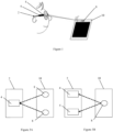
Figure 1 illustrates a head-mounted device receiving tag data emitted by an electronic Bluetooth tag placed on a device, and -
Figure 2 illustrates a chart-flow embodiment of the method for identifying a distinct device within a given range distance of a head-mounted device, -
Figure 3 illustrates a head-mounted device receiving tag data emitted by electronic wireless tags placed on a device. - Elements in the figures are illustrated for simplicity and clarity and have not necessarily been drawn to scale. For example, the dimensions of some of the elements in the figure may be exaggerated relative to other elements to help to improve the understanding of the embodiments of the present invention.
- The invention relates to a method implemented with a head-mounted device for identifying a distinct device within a given range distance of the head-mounted device.
- As illustrated on
figure 1 , the head-mounteddevice 2 comprisesreceiving means 4. The receivingmeans 4 are adapted to receive signals, such as for example wireless signals emitted by an electronicwireless tag 8. - Intrinsic properties of the receiving means 4 and the electronic
wireless tag 8 define a maximal range distance in which a distinct device can be identify. For example, such predefined range distance may be limited by the sensibility of the receiving means or the power of the wireless signal emitted by the electronicwireless tag 8. - The wireless signals may comprise signals such Bluetooth and/or Wifi and/or Near Field Communication (NFC) and/or Long Range Wide-Area Network (LoRa or LoRaWAN) and/or Low Power Wide-Area Network (SigFox) and/or radio and/or electromagnetic fields signals.
- The wireless signals are beacon signals. In the sense of the invention, beacon signals are signals that indicate the proximity or location of a device or its readiness to perform a task.
- The head-mounted device further comprises a
memory 6. Thememory 6 of the head-mounted is adapted to store data, such as for example the data received by the receiving means 4 of the head-mounteddevice 2. - Advantageously, the
electronic wireless tags 8 are placed on adistinct devices 10 and emit a specific wireless signal that allows identifying saiddistinct device 10. - As illustrated on
figure 2 , the method for identifying a distinct device according to the invention comprises a step S1 of receiving tag data. The tag data are received by the receiving means of the head-mounted device. - The tag data correspond to the wireless signals emitted by at least one electronic wireless tag placed on a distinct device.
- The electronic wireless tag placed on a distinct device may be a passive electronic wireless tag. A passive electronic wireless tag only emits an identifying signal which is specific to said passive electronic wireless tag.
- Alternatively, the electronic wireless tag placed on a distinct device may be an active electronic wireless tag. An active electronic wireless tag may process data and emit data, such as for example the processed data or an identifying signal.
- The method for identifying a distinct device according to the invention further comprises a step S2 of storing the received data. The received data are stored in the memory of the head-mounted device.
- The received data comprises at least the tag data received by the receiving means of the head-mounted device.
- The method for identifying a distinct device according to the invention further comprises a step S3 of identifying a device. The device is identified based on the stored data.
- The stored data comprises at least the tag data stored in the memory of the head-mounted device.
- Advantageously, the method according to the invention allows to accurately identify a device within a predefined range of the head-mounted device.
- Alternatively, the method for identifying a distinct device may comprise prior to the tag data receiving step, a calibrating step during which the head-mounted device and the at least one electronic wireless tag are calibrated.
- The method for identifying a distinct device may further comprise a distance determining step S11. The distance between the head-mounted device and the distinct device is determined based on the received tag data.
- During the distance determining step S11, tag data received by the receiving means of the head-mounted device are analyzed so as to determine a distance between the head-mounted device and the distinct device on which the electronic wireless tag is placed.
- With reference to
figure 2 , at least one receiving mean of the head-mounted device receives a wireless signal emitted by at least an electronic wireless tag placed on a distinct device. Knowing the intrinsic characteristics of the receiving mean of the head-mounted device receiving the wireless signal and the intrinsic characteristics of the electronic wireless tag, using basic calculation methods, the position of the electronic wireless tag may be determined, and thus the distance between the distinct device and the head-mounted device can be determined. - Alternatively, the distance between the distinct device and the head-mounted device may be determined using basic triangulation calculation between at least one receiving mean of the head-mounted device receiving wireless signals emitted by at least two electronic wireless tags placed on a single distinct device, or between at least two receiving means of the head-mounted device receiving wireless signals emitted by at least one electronic wireless tag placed on a single distinct device
- The determined distance is further stored in the memory of the head-mounted device. The determined distance stored in the memory corresponds to the distance data.
- According to an embodiment of the invention illustrated on
figure 2 , the method for identifying a distinct device may comprise an angle determining step S12a. - During the angle determining step S12a, the angle between at least one receiving mean of the head-mounted device and at least two electronic wireless tags placed on at least one distinct device is determined based on the received tag data.
- With reference to
figure 3A , tag data emitted by at least twoelectronic wireless tags 8 are received by at least one receiving mean 4 of the head-mounteddevice 2. The tag data are further analyzed so as to determine an angle between said at least one receiving mean 4 and the at least twoelectronic wireless tags 8, and thus between the head-mounteddevice 2 and thedistinct device 10 on which the at least twoelectronic wireless tags 8 are placed. - The determined angle is further stored in the memory of the head-mounted device. The determined angle stored in the memory corresponds to the angle data.
- According to another embodiment of the invention illustrated on
figure 2 , the method for identifying a distinct device may comprise an angle determining step S12b. - During the angle determining step S12b, the angle between at least two receiving means of the head-mounted device and at one electronic wireless tag placed on at least one distinct device is determined based on the received tag data.
- With reference to
figure 3B , tag data emitted by at least oneelectronic wireless tag 8 is received by at least two receiving means 4 of the head-mounteddevice 2. The tag data are further analyzed so as to determine an angle between said at least two receiving means 4 and the at least oneelectronic wireless tag 8, and thus between the head-mounteddevice 2 and thedistinct device 10 on which the at least one electronic wireless tags is placed. - The determined angle is further stored in the memory of the head-mounted device. The determined angle stored in the memory corresponds to the angle data.
- According to an embodiment of the invention illustrated on
figure 2 , the method for identifying a distinct device may comprise an environment determining step S13. - During the environment determining step S13, environment data are determined based on the received tag data. The environment data are indicative of the environment of the person.
- The environment data may relate to any parameter of the environment of the person that may have an impact on the behavior of the person wearing the head-mounted device, in particular on the visual behavior of said person.
- For example, the environment data may relate to spectral features and intensity of the light received by the person. Furthermore, the environment data may relate to temperature and/or humidity of the environment of the person, the amount and/or the type of allergens and/or pollutants contained in the environment of the person and/or an indication of the localization of the person such as indoor or outdoor and/or the place of carrying out an activity of the person, proximity to relief and/or water, etc.
- The determined environment data are further stored in the memory of the head-mounted device so that the stored data further comprise environment data.
- With reference to
figure 2 , the method for identifying a distinct device may comprise an activity determining step S4. - During the activity determining step S4, activity data are determined based on the identified device and the stored data. The activity data are indicative of the activity carried on by the person wearing the head-mounted device. Furthermore, the activity data may be indicative of the time spent by the wearer of the head-mounted device doing said activity.
- The activity carried on by the person wearing the head-mounted device may be for example, but not limited to, driving, sport, playing golf, playing tennis, practicing archery, reading, teeth brushing, paragliding, etc.
- The determined activity data are further stored in the memory of the head-mounted device so that the stored data further comprise activity data.
- With reference to
figure 2 , the method for identifying a distinct device may further comprise a viewing distance determining step S5. - During the viewing distance determining step S5, the viewing distance of a person wearing the head-mounted device is determined based on the stored data. The stored data may comprise tag data, and/or distance data, and/or angle data, and/or environment data, and/or activity data.
- In the sense of the invention, the viewing distance corresponds to the distance between the person wearing the head-mounted device and the object seen by said person.
- The head-mounted device comprising receiving means adapted to receive wireless signals and a memory adapted to store data may further comprise a function controller adapted to control at least one function of said head-mounted device.
- The controllable function of the head-mounted device may relate to an optical function, a recording function, or a notification function.
- For example, the function of the head-mounted device may be a recording function controlling an activable camera placed on the head-mounted device.
- As illustrated on
figure 2 , the method for identifying a distinct device further comprises a function modifying step S6. - During the function modifying step S6, at least one function of the head-mounted is modified based on the stored data. The controllable function is controlled by a function controller of the head-mounted device.
- For example, the head-mounted device may identify that the wearer is using a distinct device comprising a wireless tag and modify a controllable function of said head-mounted device to adapt it to the utilization of said device.
- According to an embodiment of the invention, the at least one function of the head-mounted device is modified based on the stored data when at least two distinct devices comprising a wireless tag are identified by the head-mounted device.
- According to an embodiment of the invention, the modification of the function of the head-mounted device comprises acting on the activation of a controllable function of the head-mounted device.
- According to another embodiment of the invention, the modification of the function of the head-mounted device comprises adapting said controllable function.
- The at least one function of the head-mounted device modified during the function modifying step may comprise at least a notification function.
- The function controller of the head-mounted device may modify or activate/deactivate the notification function of the head-mounted device during the function modifying step based on the stored data.
- In the sense of the invention, the notification function corresponds to a function adapted to send a notification to the person wearing the head-mounted device.
- For example, the notification function may emit a sound signal, and/or a visual signal, and/or a vibration signal to the wearer of the head-mounted device.
- For example, the head-mounted device may receive tag data identifying the driver seat of a car. Based on the received tag data stored in the memory, the head-mounted may determine that the wearer of the head-mounted device is driving a car. Based on such data, the controller of the head-mounted device may turn off the notification function of the head-mounted device that for example emits a sound every time the wearer receives an email.
- The head-mounted device may further comprise at least a controllable active lens.
- The at least one function of the head-mounted device modified during the function modifying step comprises at least an optical function.
- The function controller of the head-mounted device may modify the optical function of the controllable active lens of the head-mounted device during the function modifying step based on the stored data.
- In the sense of the invention, the optical function corresponds to a function providing for each gaze direction the effect of the optical lens on the light ray passing through the optical lens.
- For example, the head-mounted device may receive tag data identifying for example a screen. Based on the received tag data that are stored in the memory, the head-mounted may determine that the wearer of the head-mounted device is looking at the screen and that the television is placed at for example 10 meters from the wearer. Based on such data, the controller of the head-mounted device may adapt the optical function of the controllable active lens to correct, for example, a myopia of the wearer.
- The optical function may comprise dioptric function, light absorption, polarizing capability, reinforcement of contrast capacity, etc.
- According to an embodiment of the invention, the modified optical function of the controllable active lens of the head-mounted device may correspond to a transmission function.
- Accordingly, the function controller of the head-mounted device may modify the transmission function of the controllable active lens of the head-mounted device during the function modifying step based on the stored data.
- Such transmission function may for example be adapted to filter a specific range of light ray.
- For example, the head-mounted device may comprise a controllable active lens comprising an electrochromic function. In response to the identification of a device corresponding to the driver seat of a car and comprising a wireless tag, the head-mounted device may modify the electrochromic function so as to de-activate a
class 4 electrochromic function. - According to another embodiment of the invention, the modified optical function of the controllable active lens of the head-mounted device may correspond to a dioptric function.
- Accordingly, the function controller of the head-mounted device may modify the dioptric function of the controllable active lens of the head-mounted device during the function modifying step based on the stored data.
- The dioptric function corresponds to the optical lens power (mean power, astigmatism etc.) as a function of the gaze direction.
- According to another embodiment of the invention, the modified optical function of the controllable active lens of the head-mounted device may correspond to a polarization function.
- Accordingly, the function controller of the head-mounted device may modify the polarization function of the controllable active lens of the head-mounted device during the function modifying step based on the stored data.
- According to an embodiment of the invention, the head-mounted device may comprise emitting means.
- The function of the head-mounted device modified during the function modifying step may comprise at least a transmitting function.
- For example, the head-mounted device identifying a device comprising a wireless tag and corresponding to a car may activate a transmitting function. Said transmitting function may transmit a signal to a connected device such as for example a smart watch to de-activate a pedometer function of said connected device.
- For example, the head-mounted device identifying a device comprising a Bluetooth tag and corresponding to a bicycle may activate a transmitting function. Said transmitting function may transmit a signal to a connected device such as for example a smart watch to activate an activity tracking function of said connected device. The activity tracking function may for example measure and store the evolution of the heart rhythm of the wearer, and/or the amount of energy used by the wearer, and/or the distance covered.
- According to an embodiment of the invention, the head-mounted device may comprise a sensor.
- The function of head-mounted device modified during the function modifying step may comprise at least a visual behavior recording function. The sensor of the head-mounted device may record in real time the visual behavior of the wearer. The visual behavior of the wearer may relate, for example to the eyelids activity of the user, such as opening frequency and force or shift in the near point of convergence. The visual behavior data recorded in real-time may further be stored in the stored data.
- The head-mounted device may determine the level of fatigue of the user based on the stored visual behavior data.
- For example, the head-mounted device identifying a device comprising a wireless tag and corresponding to a car may activate the visual behavior recording function to determine the level of fatigue of the wearer. Based on the determined level of fatigue, the head-mounted device may alert the wearer of the risk of driving a car in such state of fatigue.
- As represented on
figure 2 , the method for identifying a distinct device may further comprise a data processing step S7. - During the data processing step S7, the stored data are processed to determine at least part of a visual profile of the wearer of the head-mounted device.
- Another aspect of the invention relates to a head-mounted device comprising one or more sequences of instructions that are accessible to a processor. The sequences of instructions, when executed by the processor, cause the processor to carry out the method according to the invention for identifying a distinct device.
- The head-mounted device may further comprise emitting and receiving means.
- The invention further relates to a system comprising at least an electronic wireless tag and at least a head-mounted device.
- The at least one electronic wireless tag emits at least a wireless signal. The at least one wireless signal allows identifying the electronic wireless tag.
- The electronic wireless tag may be a passive electronic wireless tag. A passive electronic wireless tag only emits an identifying signal which is specific to said passive electronic wireless tag.
- Alternatively, the electronic wireless tag may be an active electronic wireless tag. An active electronic wireless tag may process data and emit data, such as for example the processed data or an identifying signal.
- The at least one head-mounted device comprises receiving means. The receiving means are adapted to receive the wireless signal of the electronic wireless tag. The received wireless signal corresponds to the tag data.
- The at least one head-mounted device also comprises a memory. The memory is adapted to store the received tag data.
- The memory further comprises an executable program that when executed allows to identify the electronic wireless tag based on the receive data.
- The invention has been described above with the aid of embodiments without limitation of the general inventive concept.
- Many further modifications and variations will suggest themselves to those skilled in the art upon making reference to the foregoing illustrative embodiments, which are given by way of example only and which are not intended to limit the scope of the invention, that being determined solely by the appended claims.
- In the claims, the word "comprising" does not exclude other elements or steps, and the indefinite article "a" or "an" does not exclude a plurality. The mere fact that different features are recited in mutually different dependent claims does not indicate that a combination of these features cannot be advantageously used. Any reference signs in the claims should not be construed as limiting the scope of the invention.
Claims (13)
- Method for identifying a distinct device (10) within a given range distance of a head-mounted device (2), the head-mounted device (2) comprises:- receiving means (4) adapted to receive wireless signals,- a memory (6) adapted to store data,- a function controller adapted to control at least one function of the head-mounted device, and- at least one controllable active optical lens, the method comprising:characterized in that the method further comprises:- a tag data receiving step during which tag data identifying at least one electronic wireless tag (8) placed on the distinct device (10) are received by the receiving means (4) of the head-mounted device (2),- a storing step during which the received data comprising the tag data are stored in the memory (6) of the head-mounted device (2),- an identification step during which the distinct device (10) is identified based on the stored data,- a function modifying step during which said at least one function of the head-mounted device (2) is modified based on the stored data,wherein the function of the head-mounted device (2) modified during the function modifying step is an optical function of the active optical lens.
- The method according to claim 1, further comprising a distance determining step during which the distance between the head-mounted device (2) and the distinct device (10) is determined based on the received tag data, and wherein the determined distance is stored in the memory (6) of the head-mounted device (2), so that the stored data further comprise distance data.
- The method according to any of claim 1 or 2, further comprising an angle determining step during which the angle between the head-mounted device (2) and at least two electronic tags (8) placed on the distinct device is determined based on the received tag data, and wherein the determined angle is stored in the memory (6) of the head-mounted device (2), so that the stored data further comprise angle data.
- The method according to claim 1 or 2, further comprising an angle determining step during which the angle between at least two receiving means (4) of the head-mounted device (2) and an electronic tag (8) placed on the distinct device (10) is determined based on the received tag data, and wherein the determined angle is stored in the memory (6) of the head-mounted device (2), so that the stored data further comprise angle data.
- The method according to claim 3 or 4, wherein the method further comprises a viewing distance determining step during which the viewing distance of a wearer of the head-mounted device (2) is determined based on the stored data.
- The method according to claim 1, wherein the modification of the function of the head-mounted device (2) comprises acting on the activation of said function.
- The method according to claim 1, wherein the modification of the function of the head-mounted device (2) comprises adapting the function.
- The method according to any of claims 1 to 7, wherein the at least one function of the head-mounted device (2) comprises at least a notification function adapted to send a notification to the wearer.
- The method according to claim 1, wherein the modified active optical function is an active transmission function and wherein during the function modifying step the transmission function is modified based on the stored data.
- The method according to claim 1, wherein the modified active optical function is an active dioptric function and wherein during the function modifying step the dioptric function is modified to be adapted to the wearer based on the stored data.
- The method according to any of the preceding claims, wherein the method further comprises a data processing step during which the stored data are processed to determine at least part of a visual profile of the wearer of the head-mounted device (2).
- A head-mounted device (2) comprising:- at least a controllable active lens;- a function controller adapted to control at least one function of the head-mounted device;- receiving means (4) adapted to receive signals,- a processor,- a memory (6) configured to store one or more sequences of instructions that are accessible to a processor, and which, when executed by the processor, causes the processor to carry out a method comprising:characterized in that the one or more sequences of instructions that are accessible to a processor, and which, when executed by the processor, further causes the processor to carry out a method comprising:- a tag data receiving step during which tag data identifying an electronic wireless tag (8) placed on a distinct device (10) are received by receiving means (4) of the head-mounted device (2),- a storing step during which the received data comprising the tag data are stored in the memory (6) of the head-mounted device (2), and- an identification step during which the distinct device (10) is identified based on the stored data,- a function modifying step during which said at least one function of the head-mounted device (2) is modified based on the stored data,wherein the function of the head-mounted device (2) modified during the function modifying step is an optical function of the active optical lens.
- A system comprising:- at least an electronic wireless tag (8), the at least one electronic tag emitting an identifying wireless signal,- at least a head-mounted device (2) according to claim 12.
Priority Applications (3)
| Application Number | Priority Date | Filing Date | Title |
|---|---|---|---|
| EP19305101.8A EP3686767B1 (en) | 2019-01-25 | 2019-01-25 | Method, device and system for identifying a device |
| CN202010073283.8A CN111491280A (en) | 2019-01-25 | 2020-01-22 | Method for identifying a device |
| US16/751,756 US12092902B2 (en) | 2019-01-25 | 2020-01-24 | Head-mounted device configured to identify a device within a specific distance, and method of operation |
Applications Claiming Priority (1)
| Application Number | Priority Date | Filing Date | Title |
|---|---|---|---|
| EP19305101.8A EP3686767B1 (en) | 2019-01-25 | 2019-01-25 | Method, device and system for identifying a device |
Publications (2)
| Publication Number | Publication Date |
|---|---|
| EP3686767A1 EP3686767A1 (en) | 2020-07-29 |
| EP3686767B1 true EP3686767B1 (en) | 2024-05-22 |
Family
ID=65628722
Family Applications (1)
| Application Number | Title | Priority Date | Filing Date |
|---|---|---|---|
| EP19305101.8A Active EP3686767B1 (en) | 2019-01-25 | 2019-01-25 | Method, device and system for identifying a device |
Country Status (3)
| Country | Link |
|---|---|
| US (1) | US12092902B2 (en) |
| EP (1) | EP3686767B1 (en) |
| CN (1) | CN111491280A (en) |
Family Cites Families (18)
| Publication number | Priority date | Publication date | Assignee | Title |
|---|---|---|---|---|
| US7264354B2 (en) * | 1999-07-02 | 2007-09-04 | E-Vision, Llc | Method and apparatus for correcting vision using an electro-active phoropter |
| US7639138B2 (en) * | 2007-02-12 | 2009-12-29 | At&T Intellectual Property I, L.P. | Methods and apparatus to visualize locations of radio frequency identification (RFID) tagged items |
| US8248210B2 (en) * | 2009-06-30 | 2012-08-21 | Intermec Ip Corp. | Method and system to determine the position, orientation, size, and movement of RFID tagged objects |
| US8890657B2 (en) * | 2009-10-30 | 2014-11-18 | Symbol Technologies, Inc. | System and method for operating an RFID system with head tracking |
| JP5490918B2 (en) * | 2009-12-04 | 2014-05-14 | パロット | Electronically controlled focusing ophthalmic device |
| US8791795B2 (en) * | 2010-09-28 | 2014-07-29 | Hand Held Products, Inc. | Terminal for line-of-sight RFID tag reading |
| WO2012061440A2 (en) * | 2010-11-01 | 2012-05-10 | Nike International Ltd. | Wearable device assembly having athletic functionality |
| EP2677889A1 (en) | 2011-02-22 | 2014-01-01 | Joelmar Pty Ltd | Survival and location enhancement garment and headgear |
| WO2014128810A1 (en) * | 2013-02-22 | 2014-08-28 | ソニー株式会社 | Head-mounted display and image display device |
| EP2833196B1 (en) | 2013-08-02 | 2016-03-16 | ESSILOR INTERNATIONAL (Compagnie Générale d'Optique) | A method of controlling a programmable ophthalmic lens device |
| WO2015032824A1 (en) * | 2013-09-04 | 2015-03-12 | Essilor International (Compagnie Generale D'optique) | Methods and systems for augmented reality |
| EP3042152B1 (en) | 2013-09-04 | 2022-11-09 | Essilor International | Navigation method based on a see-through head-mounted device |
| CN105917639B (en) * | 2013-11-15 | 2019-03-19 | 福瑞佛克斯系统有限公司 | Position Tag Camera Focusing System |
| US10149958B1 (en) * | 2015-07-17 | 2018-12-11 | Bao Tran | Systems and methods for computer assisted operation |
| US20180338709A1 (en) * | 2015-12-01 | 2018-11-29 | Koninklijke Philips N.V. | Activity identification and tracking |
| EP3258308A1 (en) * | 2016-06-13 | 2017-12-20 | ESSILOR INTERNATIONAL (Compagnie Générale d'Optique) | Frame for a head mounted device |
| EP3318915B1 (en) * | 2016-11-04 | 2020-04-22 | Essilor International | Method for determining an optical performance of a head mounted display device |
| US10528780B2 (en) * | 2016-12-12 | 2020-01-07 | Symbol Technologies, Llc | Wearable mobile electronic devices |
-
2019
- 2019-01-25 EP EP19305101.8A patent/EP3686767B1/en active Active
-
2020
- 2020-01-22 CN CN202010073283.8A patent/CN111491280A/en active Pending
- 2020-01-24 US US16/751,756 patent/US12092902B2/en active Active
Also Published As
| Publication number | Publication date |
|---|---|
| EP3686767A1 (en) | 2020-07-29 |
| US20200241321A1 (en) | 2020-07-30 |
| US12092902B2 (en) | 2024-09-17 |
| CN111491280A (en) | 2020-08-04 |
Similar Documents
| Publication | Publication Date | Title |
|---|---|---|
| US9997043B2 (en) | Comprehensive system and method of universal real-time linking of real objects to a machine, network, internet, or software service | |
| US9785806B2 (en) | Low-frequency receiving for radio frequency identification | |
| US11663896B2 (en) | Comprehensive system and method of universal real-time linking of real objects to a machine, network, internet, or software service | |
| US20100090809A1 (en) | Method and apparatus for transmitting sensor status of radio frequency identification tag | |
| JP7317399B2 (en) | Electronic device and system for guiding ball drop point | |
| US10610733B2 (en) | Smart weight-lifting pin | |
| EP3293723A1 (en) | Method, storage medium, and electronic device for displaying images | |
| KR20170098109A (en) | Method for selection of transmission Antenna and electronic device supporting the same | |
| KR20170024913A (en) | Noise Cancelling Electronic Device and Noise Cancelling Method Using Plurality of Microphones | |
| US10206059B1 (en) | Positioning system and positioning method | |
| US10380468B2 (en) | Proactive transmission of measured values to mobile devices | |
| KR20160121058A (en) | Method and apparatus for operating a sensor of electronic device | |
| EP3278174B1 (en) | A monitoring system of the position of a head mounted device | |
| KR20180108192A (en) | Method for determining location, electronic apparatus and storage medium | |
| US9436859B2 (en) | Ad hoc localization using a movable reader and movable id tags | |
| KR20170059235A (en) | Method of function operation and electronic device supporting the same | |
| KR102240719B1 (en) | Method for obtaining location information and an electronic device thereof | |
| KR20160136928A (en) | Method for calibrating geomagnetic sensor and Electronic device using the same | |
| US12092902B2 (en) | Head-mounted device configured to identify a device within a specific distance, and method of operation | |
| EP3113134B1 (en) | A user fatigue level analysis component | |
| US10782542B2 (en) | Method for controlling an ophthalmic system on the basis of a measurement and information obtained by an external electronic device | |
| US10009872B2 (en) | Mobile device, operating method thereof, and non-transitory computer readable storage medium for controlling an external device | |
| US11035924B2 (en) | Method for locating animals using radio waves | |
| US20170344577A1 (en) | Biological information measuring apparatus, communication system, and communication method | |
| US20160058334A1 (en) | Activity status information computation system |
Legal Events
| Date | Code | Title | Description |
|---|---|---|---|
| PUAI | Public reference made under article 153(3) epc to a published international application that has entered the european phase |
Free format text: ORIGINAL CODE: 0009012 |
|
| STAA | Information on the status of an ep patent application or granted ep patent |
Free format text: STATUS: THE APPLICATION HAS BEEN PUBLISHED |
|
| AK | Designated contracting states |
Kind code of ref document: A1 Designated state(s): AL AT BE BG CH CY CZ DE DK EE ES FI FR GB GR HR HU IE IS IT LI LT LU LV MC MK MT NL NO PL PT RO RS SE SI SK SM TR |
|
| AX | Request for extension of the european patent |
Extension state: BA ME |
|
| STAA | Information on the status of an ep patent application or granted ep patent |
Free format text: STATUS: REQUEST FOR EXAMINATION WAS MADE |
|
| 17P | Request for examination filed |
Effective date: 20210128 |
|
| RBV | Designated contracting states (corrected) |
Designated state(s): AL AT BE BG CH CY CZ DE DK EE ES FI FR GB GR HR HU IE IS IT LI LT LU LV MC MK MT NL NO PL PT RO RS SE SI SK SM TR |
|
| STAA | Information on the status of an ep patent application or granted ep patent |
Free format text: STATUS: EXAMINATION IS IN PROGRESS |
|
| 17Q | First examination report despatched |
Effective date: 20210927 |
|
| P01 | Opt-out of the competence of the unified patent court (upc) registered |
Effective date: 20230525 |
|
| GRAP | Despatch of communication of intention to grant a patent |
Free format text: ORIGINAL CODE: EPIDOSNIGR1 |
|
| STAA | Information on the status of an ep patent application or granted ep patent |
Free format text: STATUS: GRANT OF PATENT IS INTENDED |
|
| INTG | Intention to grant announced |
Effective date: 20240306 |
|
| GRAS | Grant fee paid |
Free format text: ORIGINAL CODE: EPIDOSNIGR3 |
|
| GRAA | (expected) grant |
Free format text: ORIGINAL CODE: 0009210 |
|
| STAA | Information on the status of an ep patent application or granted ep patent |
Free format text: STATUS: THE PATENT HAS BEEN GRANTED |
|
| AK | Designated contracting states |
Kind code of ref document: B1 Designated state(s): AL AT BE BG CH CY CZ DE DK EE ES FI FR GB GR HR HU IE IS IT LI LT LU LV MC MK MT NL NO PL PT RO RS SE SI SK SM TR |
|
| REG | Reference to a national code |
Ref country code: GB Ref legal event code: FG4D |
|
| REG | Reference to a national code |
Ref country code: CH Ref legal event code: EP |
|
| REG | Reference to a national code |
Ref country code: DE Ref legal event code: R096 Ref document number: 602019052543 Country of ref document: DE |
|
| REG | Reference to a national code |
Ref country code: IE Ref legal event code: FG4D |
|
| REG | Reference to a national code |
Ref country code: LT Ref legal event code: MG9D |
|
| REG | Reference to a national code |
Ref country code: NL Ref legal event code: MP Effective date: 20240522 |
|
| PG25 | Lapsed in a contracting state [announced via postgrant information from national office to epo] |
Ref country code: IS Free format text: LAPSE BECAUSE OF FAILURE TO SUBMIT A TRANSLATION OF THE DESCRIPTION OR TO PAY THE FEE WITHIN THE PRESCRIBED TIME-LIMIT Effective date: 20240922 |
|
| PG25 | Lapsed in a contracting state [announced via postgrant information from national office to epo] |
Ref country code: BG Free format text: LAPSE BECAUSE OF FAILURE TO SUBMIT A TRANSLATION OF THE DESCRIPTION OR TO PAY THE FEE WITHIN THE PRESCRIBED TIME-LIMIT Effective date: 20240522 |
|
| PG25 | Lapsed in a contracting state [announced via postgrant information from national office to epo] |
Ref country code: HR Free format text: LAPSE BECAUSE OF FAILURE TO SUBMIT A TRANSLATION OF THE DESCRIPTION OR TO PAY THE FEE WITHIN THE PRESCRIBED TIME-LIMIT Effective date: 20240522 Ref country code: FI Free format text: LAPSE BECAUSE OF FAILURE TO SUBMIT A TRANSLATION OF THE DESCRIPTION OR TO PAY THE FEE WITHIN THE PRESCRIBED TIME-LIMIT Effective date: 20240522 |
|
| PG25 | Lapsed in a contracting state [announced via postgrant information from national office to epo] |
Ref country code: GR Free format text: LAPSE BECAUSE OF FAILURE TO SUBMIT A TRANSLATION OF THE DESCRIPTION OR TO PAY THE FEE WITHIN THE PRESCRIBED TIME-LIMIT Effective date: 20240823 |
|
| PG25 | Lapsed in a contracting state [announced via postgrant information from national office to epo] |
Ref country code: PT Free format text: LAPSE BECAUSE OF FAILURE TO SUBMIT A TRANSLATION OF THE DESCRIPTION OR TO PAY THE FEE WITHIN THE PRESCRIBED TIME-LIMIT Effective date: 20240923 |
|
| REG | Reference to a national code |
Ref country code: AT Ref legal event code: MK05 Ref document number: 1689351 Country of ref document: AT Kind code of ref document: T Effective date: 20240522 |
|
| PG25 | Lapsed in a contracting state [announced via postgrant information from national office to epo] |
Ref country code: NL Free format text: LAPSE BECAUSE OF FAILURE TO SUBMIT A TRANSLATION OF THE DESCRIPTION OR TO PAY THE FEE WITHIN THE PRESCRIBED TIME-LIMIT Effective date: 20240522 |
|
| PG25 | Lapsed in a contracting state [announced via postgrant information from national office to epo] |
Ref country code: ES Free format text: LAPSE BECAUSE OF FAILURE TO SUBMIT A TRANSLATION OF THE DESCRIPTION OR TO PAY THE FEE WITHIN THE PRESCRIBED TIME-LIMIT Effective date: 20240522 |
|
| PG25 | Lapsed in a contracting state [announced via postgrant information from national office to epo] |
Ref country code: AT Free format text: LAPSE BECAUSE OF FAILURE TO SUBMIT A TRANSLATION OF THE DESCRIPTION OR TO PAY THE FEE WITHIN THE PRESCRIBED TIME-LIMIT Effective date: 20240522 |
|
| PG25 | Lapsed in a contracting state [announced via postgrant information from national office to epo] |
Ref country code: PL Free format text: LAPSE BECAUSE OF FAILURE TO SUBMIT A TRANSLATION OF THE DESCRIPTION OR TO PAY THE FEE WITHIN THE PRESCRIBED TIME-LIMIT Effective date: 20240522 |
|
| PG25 | Lapsed in a contracting state [announced via postgrant information from national office to epo] |
Ref country code: LV Free format text: LAPSE BECAUSE OF FAILURE TO SUBMIT A TRANSLATION OF THE DESCRIPTION OR TO PAY THE FEE WITHIN THE PRESCRIBED TIME-LIMIT Effective date: 20240522 |
|
| PG25 | Lapsed in a contracting state [announced via postgrant information from national office to epo] |
Ref country code: PT Free format text: LAPSE BECAUSE OF FAILURE TO SUBMIT A TRANSLATION OF THE DESCRIPTION OR TO PAY THE FEE WITHIN THE PRESCRIBED TIME-LIMIT Effective date: 20240923 Ref country code: PL Free format text: LAPSE BECAUSE OF FAILURE TO SUBMIT A TRANSLATION OF THE DESCRIPTION OR TO PAY THE FEE WITHIN THE PRESCRIBED TIME-LIMIT Effective date: 20240522 Ref country code: NO Free format text: LAPSE BECAUSE OF FAILURE TO SUBMIT A TRANSLATION OF THE DESCRIPTION OR TO PAY THE FEE WITHIN THE PRESCRIBED TIME-LIMIT Effective date: 20240822 Ref country code: NL Free format text: LAPSE BECAUSE OF FAILURE TO SUBMIT A TRANSLATION OF THE DESCRIPTION OR TO PAY THE FEE WITHIN THE PRESCRIBED TIME-LIMIT Effective date: 20240522 Ref country code: LV Free format text: LAPSE BECAUSE OF FAILURE TO SUBMIT A TRANSLATION OF THE DESCRIPTION OR TO PAY THE FEE WITHIN THE PRESCRIBED TIME-LIMIT Effective date: 20240522 Ref country code: IS Free format text: LAPSE BECAUSE OF FAILURE TO SUBMIT A TRANSLATION OF THE DESCRIPTION OR TO PAY THE FEE WITHIN THE PRESCRIBED TIME-LIMIT Effective date: 20240922 Ref country code: HR Free format text: LAPSE BECAUSE OF FAILURE TO SUBMIT A TRANSLATION OF THE DESCRIPTION OR TO PAY THE FEE WITHIN THE PRESCRIBED TIME-LIMIT Effective date: 20240522 Ref country code: GR Free format text: LAPSE BECAUSE OF FAILURE TO SUBMIT A TRANSLATION OF THE DESCRIPTION OR TO PAY THE FEE WITHIN THE PRESCRIBED TIME-LIMIT Effective date: 20240823 Ref country code: FI Free format text: LAPSE BECAUSE OF FAILURE TO SUBMIT A TRANSLATION OF THE DESCRIPTION OR TO PAY THE FEE WITHIN THE PRESCRIBED TIME-LIMIT Effective date: 20240522 Ref country code: ES Free format text: LAPSE BECAUSE OF FAILURE TO SUBMIT A TRANSLATION OF THE DESCRIPTION OR TO PAY THE FEE WITHIN THE PRESCRIBED TIME-LIMIT Effective date: 20240522 Ref country code: BG Free format text: LAPSE BECAUSE OF FAILURE TO SUBMIT A TRANSLATION OF THE DESCRIPTION OR TO PAY THE FEE WITHIN THE PRESCRIBED TIME-LIMIT Effective date: 20240522 Ref country code: AT Free format text: LAPSE BECAUSE OF FAILURE TO SUBMIT A TRANSLATION OF THE DESCRIPTION OR TO PAY THE FEE WITHIN THE PRESCRIBED TIME-LIMIT Effective date: 20240522 Ref country code: RS Free format text: LAPSE BECAUSE OF FAILURE TO SUBMIT A TRANSLATION OF THE DESCRIPTION OR TO PAY THE FEE WITHIN THE PRESCRIBED TIME-LIMIT Effective date: 20240822 |
|
| PG25 | Lapsed in a contracting state [announced via postgrant information from national office to epo] |
Ref country code: DK Free format text: LAPSE BECAUSE OF FAILURE TO SUBMIT A TRANSLATION OF THE DESCRIPTION OR TO PAY THE FEE WITHIN THE PRESCRIBED TIME-LIMIT Effective date: 20240522 |
|
| PG25 | Lapsed in a contracting state [announced via postgrant information from national office to epo] |
Ref country code: EE Free format text: LAPSE BECAUSE OF FAILURE TO SUBMIT A TRANSLATION OF THE DESCRIPTION OR TO PAY THE FEE WITHIN THE PRESCRIBED TIME-LIMIT Effective date: 20240522 |
|
| PG25 | Lapsed in a contracting state [announced via postgrant information from national office to epo] |
Ref country code: CZ Free format text: LAPSE BECAUSE OF FAILURE TO SUBMIT A TRANSLATION OF THE DESCRIPTION OR TO PAY THE FEE WITHIN THE PRESCRIBED TIME-LIMIT Effective date: 20240522 |
|
| PG25 | Lapsed in a contracting state [announced via postgrant information from national office to epo] |
Ref country code: SK Free format text: LAPSE BECAUSE OF FAILURE TO SUBMIT A TRANSLATION OF THE DESCRIPTION OR TO PAY THE FEE WITHIN THE PRESCRIBED TIME-LIMIT Effective date: 20240522 Ref country code: RO Free format text: LAPSE BECAUSE OF FAILURE TO SUBMIT A TRANSLATION OF THE DESCRIPTION OR TO PAY THE FEE WITHIN THE PRESCRIBED TIME-LIMIT Effective date: 20240522 |
|
| PG25 | Lapsed in a contracting state [announced via postgrant information from national office to epo] |
Ref country code: SM Free format text: LAPSE BECAUSE OF FAILURE TO SUBMIT A TRANSLATION OF THE DESCRIPTION OR TO PAY THE FEE WITHIN THE PRESCRIBED TIME-LIMIT Effective date: 20240522 |
|
| PG25 | Lapsed in a contracting state [announced via postgrant information from national office to epo] |
Ref country code: SM Free format text: LAPSE BECAUSE OF FAILURE TO SUBMIT A TRANSLATION OF THE DESCRIPTION OR TO PAY THE FEE WITHIN THE PRESCRIBED TIME-LIMIT Effective date: 20240522 Ref country code: SK Free format text: LAPSE BECAUSE OF FAILURE TO SUBMIT A TRANSLATION OF THE DESCRIPTION OR TO PAY THE FEE WITHIN THE PRESCRIBED TIME-LIMIT Effective date: 20240522 Ref country code: RO Free format text: LAPSE BECAUSE OF FAILURE TO SUBMIT A TRANSLATION OF THE DESCRIPTION OR TO PAY THE FEE WITHIN THE PRESCRIBED TIME-LIMIT Effective date: 20240522 Ref country code: EE Free format text: LAPSE BECAUSE OF FAILURE TO SUBMIT A TRANSLATION OF THE DESCRIPTION OR TO PAY THE FEE WITHIN THE PRESCRIBED TIME-LIMIT Effective date: 20240522 Ref country code: DK Free format text: LAPSE BECAUSE OF FAILURE TO SUBMIT A TRANSLATION OF THE DESCRIPTION OR TO PAY THE FEE WITHIN THE PRESCRIBED TIME-LIMIT Effective date: 20240522 Ref country code: CZ Free format text: LAPSE BECAUSE OF FAILURE TO SUBMIT A TRANSLATION OF THE DESCRIPTION OR TO PAY THE FEE WITHIN THE PRESCRIBED TIME-LIMIT Effective date: 20240522 |
|
| PG25 | Lapsed in a contracting state [announced via postgrant information from national office to epo] |
Ref country code: IT Free format text: LAPSE BECAUSE OF FAILURE TO SUBMIT A TRANSLATION OF THE DESCRIPTION OR TO PAY THE FEE WITHIN THE PRESCRIBED TIME-LIMIT Effective date: 20240522 |
|
| REG | Reference to a national code |
Ref country code: DE Ref legal event code: R097 Ref document number: 602019052543 Country of ref document: DE |
|
| PLBE | No opposition filed within time limit |
Free format text: ORIGINAL CODE: 0009261 |
|
| STAA | Information on the status of an ep patent application or granted ep patent |
Free format text: STATUS: NO OPPOSITION FILED WITHIN TIME LIMIT |
|
| PG25 | Lapsed in a contracting state [announced via postgrant information from national office to epo] |
Ref country code: SI Free format text: LAPSE BECAUSE OF FAILURE TO SUBMIT A TRANSLATION OF THE DESCRIPTION OR TO PAY THE FEE WITHIN THE PRESCRIBED TIME-LIMIT Effective date: 20240522 |
|
| 26N | No opposition filed |
Effective date: 20250225 |
|
| REG | Reference to a national code |
Ref country code: CH Ref legal event code: PL |
|
| PG25 | Lapsed in a contracting state [announced via postgrant information from national office to epo] |
Ref country code: SE Free format text: LAPSE BECAUSE OF FAILURE TO SUBMIT A TRANSLATION OF THE DESCRIPTION OR TO PAY THE FEE WITHIN THE PRESCRIBED TIME-LIMIT Effective date: 20240522 |
|
| PG25 | Lapsed in a contracting state [announced via postgrant information from national office to epo] |
Ref country code: MC Free format text: LAPSE BECAUSE OF FAILURE TO SUBMIT A TRANSLATION OF THE DESCRIPTION OR TO PAY THE FEE WITHIN THE PRESCRIBED TIME-LIMIT Effective date: 20240522 Ref country code: LU Free format text: LAPSE BECAUSE OF NON-PAYMENT OF DUE FEES Effective date: 20250125 |
|
| PG25 | Lapsed in a contracting state [announced via postgrant information from national office to epo] |
Ref country code: BE Free format text: LAPSE BECAUSE OF NON-PAYMENT OF DUE FEES Effective date: 20250131 |
|
| PG25 | Lapsed in a contracting state [announced via postgrant information from national office to epo] |
Ref country code: CH Free format text: LAPSE BECAUSE OF NON-PAYMENT OF DUE FEES Effective date: 20250131 |
|
| REG | Reference to a national code |
Ref country code: BE Ref legal event code: MM Effective date: 20250131 |
|
| PG25 | Lapsed in a contracting state [announced via postgrant information from national office to epo] |
Ref country code: IE Free format text: LAPSE BECAUSE OF NON-PAYMENT OF DUE FEES Effective date: 20250125 |
|
| PGFP | Annual fee paid to national office [announced via postgrant information from national office to epo] |
Ref country code: GB Payment date: 20260127 Year of fee payment: 8 |
|
| PGFP | Annual fee paid to national office [announced via postgrant information from national office to epo] |
Ref country code: DE Payment date: 20260128 Year of fee payment: 8 |
|
| PGFP | Annual fee paid to national office [announced via postgrant information from national office to epo] |
Ref country code: FR Payment date: 20260126 Year of fee payment: 8 |