EP3686702B1 - Torque-limiter health monitoring - Google Patents
Torque-limiter health monitoring Download PDFInfo
- Publication number
- EP3686702B1 EP3686702B1 EP20156474.7A EP20156474A EP3686702B1 EP 3686702 B1 EP3686702 B1 EP 3686702B1 EP 20156474 A EP20156474 A EP 20156474A EP 3686702 B1 EP3686702 B1 EP 3686702B1
- Authority
- EP
- European Patent Office
- Prior art keywords
- sensor
- torque
- limiter
- ball
- distance
- Prior art date
- Legal status (The legal status is an assumption and is not a legal conclusion. Google has not performed a legal analysis and makes no representation as to the accuracy of the status listed.)
- Active
Links
Images




Classifications
-
- G—PHYSICS
- G05—CONTROLLING; REGULATING
- G05D—SYSTEMS FOR CONTROLLING OR REGULATING NON-ELECTRIC VARIABLES
- G05D17/00—Control of torque; Control of mechanical power
- G05D17/02—Control of torque; Control of mechanical power characterised by the use of electric means
-
- F—MECHANICAL ENGINEERING; LIGHTING; HEATING; WEAPONS; BLASTING
- F16—ENGINEERING ELEMENTS AND UNITS; GENERAL MEASURES FOR PRODUCING AND MAINTAINING EFFECTIVE FUNCTIONING OF MACHINES OR INSTALLATIONS; THERMAL INSULATION IN GENERAL
- F16D—COUPLINGS FOR TRANSMITTING ROTATION; CLUTCHES; BRAKES
- F16D3/00—Yielding couplings, i.e. with means permitting movement between the connected parts during the drive
- F16D3/16—Universal joints in which flexibility is produced by means of pivots or sliding or rolling connecting parts
- F16D3/20—Universal joints in which flexibility is produced by means of pivots or sliding or rolling connecting parts one coupling part entering a sleeve of the other coupling part and connected thereto by sliding or rolling members
- F16D3/22—Universal joints in which flexibility is produced by means of pivots or sliding or rolling connecting parts one coupling part entering a sleeve of the other coupling part and connected thereto by sliding or rolling members the rolling members being balls, rollers, or the like, guided in grooves or sockets in both coupling parts
-
- F—MECHANICAL ENGINEERING; LIGHTING; HEATING; WEAPONS; BLASTING
- F16—ENGINEERING ELEMENTS AND UNITS; GENERAL MEASURES FOR PRODUCING AND MAINTAINING EFFECTIVE FUNCTIONING OF MACHINES OR INSTALLATIONS; THERMAL INSULATION IN GENERAL
- F16D—COUPLINGS FOR TRANSMITTING ROTATION; CLUTCHES; BRAKES
- F16D43/00—Automatic clutches
- F16D43/02—Automatic clutches actuated entirely mechanically
- F16D43/20—Automatic clutches actuated entirely mechanically controlled by torque, e.g. overload-release clutches, slip-clutches with means by which torque varies the clutching pressure
- F16D43/202—Automatic clutches actuated entirely mechanically controlled by torque, e.g. overload-release clutches, slip-clutches with means by which torque varies the clutching pressure of the ratchet type
- F16D43/204—Automatic clutches actuated entirely mechanically controlled by torque, e.g. overload-release clutches, slip-clutches with means by which torque varies the clutching pressure of the ratchet type with intermediate balls or rollers
- F16D43/206—Automatic clutches actuated entirely mechanically controlled by torque, e.g. overload-release clutches, slip-clutches with means by which torque varies the clutching pressure of the ratchet type with intermediate balls or rollers moving axially between engagement and disengagement
-
- F—MECHANICAL ENGINEERING; LIGHTING; HEATING; WEAPONS; BLASTING
- F16—ENGINEERING ELEMENTS AND UNITS; GENERAL MEASURES FOR PRODUCING AND MAINTAINING EFFECTIVE FUNCTIONING OF MACHINES OR INSTALLATIONS; THERMAL INSULATION IN GENERAL
- F16D—COUPLINGS FOR TRANSMITTING ROTATION; CLUTCHES; BRAKES
- F16D7/00—Slip couplings, e.g. slipping on overload, for absorbing shock
- F16D7/005—Slip couplings, e.g. slipping on overload, for absorbing shock the torque being transmitted and limited by rolling friction, e.g. ball bearings axially loaded
-
- F—MECHANICAL ENGINEERING; LIGHTING; HEATING; WEAPONS; BLASTING
- F16—ENGINEERING ELEMENTS AND UNITS; GENERAL MEASURES FOR PRODUCING AND MAINTAINING EFFECTIVE FUNCTIONING OF MACHINES OR INSTALLATIONS; THERMAL INSULATION IN GENERAL
- F16D—COUPLINGS FOR TRANSMITTING ROTATION; CLUTCHES; BRAKES
- F16D7/00—Slip couplings, e.g. slipping on overload, for absorbing shock
- F16D7/04—Slip couplings, e.g. slipping on overload, for absorbing shock of the ratchet type
- F16D7/06—Slip couplings, e.g. slipping on overload, for absorbing shock of the ratchet type with intermediate balls or rollers
- F16D7/08—Slip couplings, e.g. slipping on overload, for absorbing shock of the ratchet type with intermediate balls or rollers moving axially between engagement and disengagement
-
- F—MECHANICAL ENGINEERING; LIGHTING; HEATING; WEAPONS; BLASTING
- F16—ENGINEERING ELEMENTS AND UNITS; GENERAL MEASURES FOR PRODUCING AND MAINTAINING EFFECTIVE FUNCTIONING OF MACHINES OR INSTALLATIONS; THERMAL INSULATION IN GENERAL
- F16D—COUPLINGS FOR TRANSMITTING ROTATION; CLUTCHES; BRAKES
- F16D7/00—Slip couplings, e.g. slipping on overload, for absorbing shock
- F16D7/04—Slip couplings, e.g. slipping on overload, for absorbing shock of the ratchet type
- F16D7/06—Slip couplings, e.g. slipping on overload, for absorbing shock of the ratchet type with intermediate balls or rollers
- F16D7/10—Slip couplings, e.g. slipping on overload, for absorbing shock of the ratchet type with intermediate balls or rollers moving radially between engagement and disengagement
-
- G—PHYSICS
- G01—MEASURING; TESTING
- G01B—MEASURING LENGTH, THICKNESS OR SIMILAR LINEAR DIMENSIONS; MEASURING ANGLES; MEASURING AREAS; MEASURING IRREGULARITIES OF SURFACES OR CONTOURS
- G01B21/00—Measuring arrangements or details thereof, where the measuring technique is not covered by the other groups of this subclass, unspecified or not relevant
- G01B21/16—Measuring arrangements or details thereof, where the measuring technique is not covered by the other groups of this subclass, unspecified or not relevant for measuring distance of clearance between spaced objects
-
- G—PHYSICS
- G01—MEASURING; TESTING
- G01M—TESTING STATIC OR DYNAMIC BALANCE OF MACHINES OR STRUCTURES; TESTING OF STRUCTURES OR APPARATUS, NOT OTHERWISE PROVIDED FOR
- G01M13/00—Testing of machine parts
- G01M13/02—Gearings; Transmission mechanisms
- G01M13/022—Power-transmitting couplings or clutches
-
- G—PHYSICS
- G05—CONTROLLING; REGULATING
- G05B—CONTROL OR REGULATING SYSTEMS IN GENERAL; FUNCTIONAL ELEMENTS OF SUCH SYSTEMS; MONITORING OR TESTING ARRANGEMENTS FOR SUCH SYSTEMS OR ELEMENTS
- G05B23/00—Testing or monitoring of control systems or parts thereof
- G05B23/02—Electric testing or monitoring
- G05B23/0205—Electric testing or monitoring by means of a monitoring system capable of detecting and responding to faults
- G05B23/0259—Electric testing or monitoring by means of a monitoring system capable of detecting and responding to faults characterized by the response to fault detection
- G05B23/0283—Predictive maintenance, e.g. involving the monitoring of a system and, based on the monitoring results, taking decisions on the maintenance schedule of the monitored system; Estimating remaining useful life [RUL]
-
- B—PERFORMING OPERATIONS; TRANSPORTING
- B64—AIRCRAFT; AVIATION; COSMONAUTICS
- B64D—EQUIPMENT FOR FITTING IN OR TO AIRCRAFT; FLIGHT SUITS; PARACHUTES; ARRANGEMENT OR MOUNTING OF POWER PLANTS OR PROPULSION TRANSMISSIONS IN AIRCRAFT
- B64D45/00—Aircraft indicators or protectors not otherwise provided for
- B64D2045/0085—Devices for aircraft health monitoring, e.g. monitoring flutter or vibration
-
- B—PERFORMING OPERATIONS; TRANSPORTING
- B64—AIRCRAFT; AVIATION; COSMONAUTICS
- B64D—EQUIPMENT FOR FITTING IN OR TO AIRCRAFT; FLIGHT SUITS; PARACHUTES; ARRANGEMENT OR MOUNTING OF POWER PLANTS OR PROPULSION TRANSMISSIONS IN AIRCRAFT
- B64D45/00—Aircraft indicators or protectors not otherwise provided for
-
- F—MECHANICAL ENGINEERING; LIGHTING; HEATING; WEAPONS; BLASTING
- F16—ENGINEERING ELEMENTS AND UNITS; GENERAL MEASURES FOR PRODUCING AND MAINTAINING EFFECTIVE FUNCTIONING OF MACHINES OR INSTALLATIONS; THERMAL INSULATION IN GENERAL
- F16H—GEARING
- F16H35/00—Gearings or mechanisms with other special functional features
- F16H35/10—Arrangements or devices for absorbing overload or preventing damage by overload
- F16H2035/106—Monitoring of overload
Definitions
- the following description relates to torque-limiters and, more specifically, to health monitoring of aircraft actuation systems.
- a predictive system in claim 1 and includes a torque-limiter comprising a ball-ramp mechanism, a sensor disposed to sense a condition of the torque-limiter, the condition comprising a distance between plates of the ball-ramp mechanism, and a processing system.
- the processing system is coupled to the sensor and configured to process readings of the sensor, to calculate whether the condition of the torque-limiter is indicative of degradation or failure incidents based on the readings being processed and to determine whether an action should be taken based on a calculation result.
- the processing system calculates that the condition of the torque-limiter is indicative of the degradation or failure incidents based on the condition exceeding a first threshold or reaching a second threshold, respectively
- the torque-limiter and the sensor are mounted in a housing.
- the senor includes at least one or more proximity sensors.
- the at least one or more proximity sensors include at least one or more of an optical sensor, an electromagnetic sensor, a Hall Effect sensor, a linear variable differential transformer (LVDT) sensor and a capacitive sensor.
- an optical sensor an electromagnetic sensor
- a Hall Effect sensor a Hall Effect sensor
- LVDT linear variable differential transformer
- the processing system includes at least one or more of a controller and a prognostic maintenance computer.
- the action includes arranging maintenance.
- a predictive system for use with a ball-ramp mechanism.
- the ball-ramp mechanism includes a first plate to which an input shaft is coupled, a second plate to which an output shaft is coupled and a ball element which is disposable within complementary recesses in the first and second plates.
- the predictive system includes a sensor disposed to sense a distance between the first and second plates in a dimension defined along a longitudinal axis of the input and output shafts and a processing system.
- the processing system is coupled to the sensor and configured to process readings of the sensor, to calculate whether the distance between the first and second plates is indicative of degradation or failure incidents based on the readings being processed and to determine whether an action should be taken based on a calculation result.
- a predictive system is provided and may be used with a torque-limiter or another suitable similar mechanism.
- the predictive system includes a sensor that monitors changes in the available system torque over time using a springloaded ball-ramp mechanism.
- the sensor can be located at various points along a driveline, in a power drive unit or in an actuator.
- the ball-ramp mechanism allows torque to be passed from one shaft to another shaft without its plates moving relative to one another. However, if torque exceeds a predefined value, the balls of the ball-ramp mechanism will rise in the pockets of the plates and push the plates apart.
- the ball-ramp mechanism will provide for a visual indication after an incident of the plates being pushed apart. This visual indication must be observed manually requiring time and, in some cases, the removal of surrounding paneling.
- the sensor can continuously monitor relative plate movement and send signals that are indicative of relative plate movement to a processing system. The processing system can then determine whether the relative plate movement is greater than a predetermined threshold without exceeding overload limits while taking into consideration component wear over time and other similar issues. In addition, the processing system can take an action based on its determination so as to avoid or prevent overload conditions.
- a predictive system 10 (see FIGS. 2 and 3 ) is provided for use with a torque-limiter, such as a ball-ramp mechanism or another similar mechanism of an aircraft 30, for example.
- the aircraft 30 includes a fuselage 31 and a wing 32 extending outwardly from the fuselage 31.
- the wing 32 includes one or more flight control surfaces 33, such as slats or flaps, that are arranged along a trailing edge of the wing 32 and which are pivotable relative to a major plane of the wing 32 for executing various flight maneuvers.
- the pivoting of the flight control surfaces 33 is driven by a control unit 34 which is coupled to the flight control surfaces 33 by way of a drivetrain 35 and a series of linear or rotary actuators 36.
- Torque for powering the pivoting is generated in the control unit 34 and transmitted along the drivetrain 35 through one or more torque-limiters 37 that may be separate from (see FIG. 1A ) or integrated within (see FIG. 1B ) the actuators 36.
- Each of the torque-limiters 37 operate by preventing application of excessive load to aircraft structures in the case of an external issue. Often, the actuators 36 fail as a result of internal tare losses that exceed design parameters due to water ingress or faulty maintenance leading to corrosion or gear wear. The failure in turn leads to high input torque being required to make the actuator 36 move or respond. Eventually, the problem decays until the required torque exceeds a threshold of the torque-limiters 37.
- Conventional torque-limiter systems include tripped spring indicators that provide a visual indication of a trip incident. This trip indication needs to be observed, however, and such observation is typically preceded by removal of one or more aircraft panels.
- a sensor is provided to sense conditions of the torque-limiters 37 which do not necessarily rise to the level of a full tripping incident. Such conditions, once sensed or detected, may be compared against prior flight data and other information to aid in a determination that maintenance is or is not required.
- a torque-limiter 37 is provided as a ball-ramp mechanism 40.
- the ball-ramp mechanism 40 includes an input shaft 41 and an output shaft 42 which may be components of the drivetrain 35 of FIGS. 1A and 1B .
- the ball-ramp mechanism 40 further includes a first plate 43 to which the input shaft 41 is coupled, a second plate 44 to which the output shaft 42 is coupled, a ball element 45 which is disposable within complementary recesses 430 and 440 in the first and second plates 43 and 44, respectively, and a spring-loading assembly 46 that biases the first plate 43 toward the second plate 44 on either side of the ball element 45.
- the ball element 45 is secured within the complementary recesses 430 and 440 so that torque can be transmitted from the input shaft 41, to the first plate 43, to the ball element 45, to the second plate 44 and finally to the output shaft 42.
- the ball element 45 may translate slightly outwardly from the recesses 430 and 440 without actually leaving the recesses 430 and 440. This will have the effect of pushing the first and second plates 43 and 44 slightly apart but will still permit torque transmission from the input shaft 41 to the output shaft 42.
- the ball element 45 may translate completely out from the recesses 430 and 440. This will have the effect of pushing the first and second plates 43 and 44 apart and will prevent torque transmission from the input shaft 41 to the output shaft 42.
- the predictive system 10 includes at least one or more sensors (hereinafter referred to as "a sensor") 11, a processing system 12 and a housing 13 in which the torque-limiter 37/ball-ramp mechanism 40 and the sensor 11 are mounted so as to be normally fixed relative to one another.
- the sensor 11 may be provided as at least one or more of an optical sensor, an electromagnetic sensor, a Hall Effect sensor, a linear variable differential transformer (LVDT) sensor and a capacitive sensor.
- the sensor 11 is disposed to sense a condition of the torque-limiter 37 or, more particularly, the ball-ramp mechanism 40.
- sensor 11 may sense a first distance D1 (see FIGS.
- first and second distances D1 and D2 may but are not required to extend along a dimension that is defined along a longitudinal axis of the input and output shafts 41 and 42.
- the processing system 12 is coupled to the sensor 11 and, in some cases, to at least one or more of the control unit 34 and a flight control computer (FCC) 301 of the aircraft 30.
- the processing system is configured to process readings of the sensor 11, to calculate whether the second distance D2 between the first and second plates 41 and 42 is indicative of degradation or failure incidents in at least any one or more of the drivetrain 35 (see FIGS. 1A and 1B ), the actuators 36 (see FIGS. 1A and 1B ) and the ball-ramp mechanism 40 based on the readings being processed and to determine whether an action should be taken based on a calculation result.
- the processing system 12 may include or be provided as at least one or more of a controller 120 and a prognostic maintenance computer 121.
- the processing system 12 may include a processor 122, such as a central processing unit (CPU), a memory unit 123 and a networking unit 124 by which the processor 122 is communicative with the sensor 11 and, where applicable, the control unit 34 and the FCC 301.
- the memory unit 123 has data stored thereon which is reflective of at least historical sensor readings 11 from the ball-ramp mechanism 40 or from other ball-ramp mechanisms and executable instructions. When executed by the processor 122, the executable instructions cause the processor 122 and the processing system 12 as a whole to operate as described herein.
- the ball-ramp mechanism 40 is operating normally with the ball element 45 secured in the recesses 430 and 440.
- the sensor 11 senses that the first distance D1 between the sensor 11 and the first plate 43 is large enough to infer that the second distance D2 is short due to the ball element 45 being secured in the recesses 430 and 440.
- the ball-ramp mechanism 40 is able to transmit torque but is not operating normally due to the ball element 45 translating slightly outwardly from the recesses 430 and 440.
- the sensor 11 senses that the first distance D 1 between the sensor 11 and the first plate 43 is reduced as compared to the first distance D1 of FIG. 4 and thus it can be inferred that the second distance D2 is correspondingly elevated due to the ball element 45 being unsecured in but not completely removed from the recesses 430 and 440.
- the ball-ramp mechanism 40 is incapable of transmitting torque due to the ball element 45 being completely removed from the recesses 430 and 440.
- the sensor 11 senses that the first distance D1 between the sensor 11 and the first plate 43 is reduced as compared to the first distance D1 of FIG. 5 and thus it can be inferred that the second distance D2 is correspondingly elevated as compared to the second distance D2 in FIG. 5 due to the ball element 45 being completely removed from the recesses 430 and 440.
- the condition of the torque-limiter 37 is indicative of an increased torque but not necessarily a torque overload due to the second distance D2 between the first and second plates 43 and 44 of the ball-ramp mechanism 40 exceeding a first threshold but not reaching a second threshold.
- the processing system 12 may predefine the first threshold in accordance with at least the structural features of the ball-ramp mechanism 40 and the historical data of the memory unit 123 and take an action which is consistent with a conclusion that the condition is indicative of some degradative incident in the drivetrain 35, the actuator 36 or the torque-limiter 37/ball-ramp mechanism 40.
- Such action may include identifying a location of the torque-limiter 37 in question so that remote panel removal and inspection is not needed and at least one of instructing the control unit 34 to reduce applied torque by way of the controller 120 and arranging for maintenance by way of the prognostic maintenance computer 121 (e.g., scheduling an inspection or repair, ordering parts, etc.).
- the condition of the torque-limiter 37 is indicative of a torque overload due to the second distance D2 between the first and second plates 43 and 44 of the ball-ramp mechanism 40 reaching or substantially reaching the second threshold (the second threshold may not be able to be exceeded).
- the processing system 12 may take an action which is consistent with a conclusion that the condition is indicative of some failure incident in the drivetrain 35, the actuator 36, the torque-limiter 37 or the ball-ramp mechanism 40.
- Such action may include identifying a location of the torque-limiter 37 in question so that remote panel removal and inspection is not needed, instructing the control unit 34 to reduce or cease applied torque by way of the controller 120 and arranging for maintenance by way of the prognostic maintenance computer 121 (e.g., scheduling an inspection or repair, ordering parts, etc.).
- the method includes sensing a condition of the torque-limiter, such as a distance between plates of a ball-ramp mechanism (block 701), calculating whether the condition of the torque-limiter is indicative of a degradation or failure incident (block 702), determining whether an action should be taken based on a calculation result (block 703) and taking the action based on a result of the determining of block 703 (block 704).
- a condition of the torque-limiter such as a distance between plates of a ball-ramp mechanism
- the calculating of block 702 may include calculating that the distance exceeds a first threshold without reaching a second threshold (block 701), determining that the condition is indicative of the degradation incident based on the distance exceeding the first threshold without reaching the second threshold (block 7022), calculating that the distance reaches the second threshold (block 7023) and determining that the condition is indicative of the failure incident based on the distance reaching the second threshold (block 7024).
- the action in an event of a degradation incident, may include identifying a location of the torque-limiter in question so that remote panel removal and inspection is not needed and at least one of instructing the control unit to reduce applied torque by way of the controller and arranging for maintenance by way of the prognostic maintenance computer (e.g., scheduling an inspection or repair, ordering parts, etc.).
- the action in an event of a failure incident, may include identifying a location of the torque-limiter in question so that remote panel removal and inspection is not needed, instructing the control unit to reduce applied torque by way of the controller and arranging for maintenance by way of the prognostic maintenance computer (e.g., scheduling an inspection or repair, ordering parts, etc.).
Landscapes
- Engineering & Computer Science (AREA)
- General Engineering & Computer Science (AREA)
- Mechanical Engineering (AREA)
- Physics & Mathematics (AREA)
- General Physics & Mathematics (AREA)
- Automation & Control Theory (AREA)
- Testing Of Devices, Machine Parts, Or Other Structures Thereof (AREA)
- Transmission Devices (AREA)
- One-Way And Automatic Clutches, And Combinations Of Different Clutches (AREA)
- Management, Administration, Business Operations System, And Electronic Commerce (AREA)
- Details Of Spanners, Wrenches, And Screw Drivers And Accessories (AREA)
- Control Of Transmission Device (AREA)
Description
- The following description relates to torque-limiters and, more specifically, to health monitoring of aircraft actuation systems.
- Preventative maintenance in actuation systemis becoming increasingly important in various fields, including, for example, aircraft technologies as airlines strive to increase operational efficiency. One way to achieve this goal is to have a predictive system available to anticipate failures before they occur. Currently, on-condition service results in unscheduled repairs with potential delays due to parts and maintenance crews being unavailable right away. On the other hand, predictive systems allow operators to make arrangements for repair (e.g., by obtaining parts and ensuring availabilities of maintenance crews) in advance and thus reduce time required to return an aircraft to service. Advanced planning can also reduce inventories for operator or service centers as parts can be ordered ahead of repair times.
US 2015/0076283 relates to a method of monitoring a flap system, and a flap system.EP 2666716 relates to an integrated torque limiter/no-back device. - According to an aspect of the disclosure, a predictive system is provided in claim 1 and includes a torque-limiter comprising a ball-ramp mechanism, a sensor disposed to sense a condition of the torque-limiter, the condition comprising a distance between plates of the ball-ramp mechanism, and a processing system. The processing system is coupled to the sensor and configured to process readings of the sensor, to calculate whether the condition of the torque-limiter is indicative of degradation or failure incidents based on the readings being processed and to determine whether an action should be taken based on a calculation result. The processing system calculates that the condition of the torque-limiter is indicative of the degradation or failure incidents based on the condition exceeding a first threshold or reaching a second threshold, respectively
- [deleted]
- In accordance with additional or alternative embodiments, the torque-limiter and the sensor are mounted in a housing.
- In accordance with additional or alternative embodiments, the sensor includes at least one or more proximity sensors.
- In accordance with additional or alternative embodiments, the at least one or more proximity sensors include at least one or more of an optical sensor, an electromagnetic sensor, a Hall Effect sensor, a linear variable differential transformer (LVDT) sensor and a capacitive sensor.
- In accordance with additional or alternative embodiments, the processing system includes at least one or more of a controller and a prognostic maintenance computer.
- [deleted]
- In accordance with additional or alternative embodiments, the action includes arranging maintenance.
- According to another example of the disclosure, a predictive system is provided for use with a ball-ramp mechanism. The ball-ramp mechanism includes a first plate to which an input shaft is coupled, a second plate to which an output shaft is coupled and a ball element which is disposable within complementary recesses in the first and second plates. The predictive system includes a sensor disposed to sense a distance between the first and second plates in a dimension defined along a longitudinal axis of the input and output shafts and a processing system. The processing system is coupled to the sensor and configured to process readings of the sensor, to calculate whether the distance between the first and second plates is indicative of degradation or failure incidents based on the readings being processed and to determine whether an action should be taken based on a calculation result.
- [deleted]
- [deleted]
- [deleted]
- [deleted]
- [deleted]
- [deleted]
- [deleted]
- [deleted]
- [deleted]
- [deleted]
- [deleted]
- These and other advantages and features will become more apparent from the following description taken in conjunction with the drawings.
- The subject matter, which is regarded as the disclosure, is particularly pointed out and distinctly claimed in the claims at the conclusion of the specification. The foregoing and other features, and advantages of the disclosure are apparent from the following detailed description taken in conjunction with the accompanying drawings in which:
-
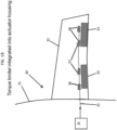
FIG. 1A is a partially cutaway top-down view of a portion of an aircraft in accordance with embodiments; -
FIG. 1B is a partially cutaway top-down view of a portion of an aircraft in accordance with alternative embodiments; -
FIG. 2 is a schematic diagram of a predictive system for use with a torque-limiter of the aircraft ofFIGS. 1A and1B ; -
FIG. 3 is a schematic diagram of a processing system of the predictive system ofFIG. 2 ; -
FIG. 4 is an illustration of an operation of the predictive and processing systems ofFIGS. 2 and 3 ; -
FIG. 5 is an illustration of an operation of the predictive and processing systems ofFIGS. 2 and 3 ; -
FIG. 6 is an illustration of an operation of the predictive and processing systems ofFIGS. 2 and 3 ; and -
FIG. 7 is a flow diagram illustrating a method of operating a predictive system in accordance with embodiments. - These and other advantages and features will become more apparent from the following description taken in conjunction with the drawings.
- As will be described below, a predictive system is provided and may be used with a torque-limiter or another suitable similar mechanism. In the case of the predictive system being used with a torque-limiter and in the case of the torque-limiter being provided as a ball-ramp mechanism, the predictive system includes a sensor that monitors changes in the available system torque over time using a springloaded ball-ramp mechanism. The sensor can be located at various points along a driveline, in a power drive unit or in an actuator. Under normal conditions, the ball-ramp mechanism allows torque to be passed from one shaft to another shaft without its plates moving relative to one another. However, if torque exceeds a predefined value, the balls of the ball-ramp mechanism will rise in the pockets of the plates and push the plates apart. In conventional applications, the ball-ramp mechanism will provide for a visual indication after an incident of the plates being pushed apart. This visual indication must be observed manually requiring time and, in some cases, the removal of surrounding paneling. In the predictive system, however, the sensor can continuously monitor relative plate movement and send signals that are indicative of relative plate movement to a processing system. The processing system can then determine whether the relative plate movement is greater than a predetermined threshold without exceeding overload limits while taking into consideration component wear over time and other similar issues. In addition, the processing system can take an action based on its determination so as to avoid or prevent overload conditions.
- With reference to
FIGS. 1A ,1B ,2 and 3 , a predictive system 10 (seeFIGS. 2 and 3 ) is provided for use with a torque-limiter, such as a ball-ramp mechanism or another similar mechanism of anaircraft 30, for example. - In the exemplary cases of
FIGS. 1A and1B , theaircraft 30 includes afuselage 31 and awing 32 extending outwardly from thefuselage 31. Thewing 32 includes one or moreflight control surfaces 33, such as slats or flaps, that are arranged along a trailing edge of thewing 32 and which are pivotable relative to a major plane of thewing 32 for executing various flight maneuvers. The pivoting of the flight control surfaces 33 is driven by acontrol unit 34 which is coupled to theflight control surfaces 33 by way of adrivetrain 35 and a series of linear orrotary actuators 36. Torque for powering the pivoting is generated in thecontrol unit 34 and transmitted along thedrivetrain 35 through one or more torque-limiters 37 that may be separate from (seeFIG. 1A ) or integrated within (seeFIG. 1B ) theactuators 36. - Each of the torque-
limiters 37 operate by preventing application of excessive load to aircraft structures in the case of an external issue. Often, theactuators 36 fail as a result of internal tare losses that exceed design parameters due to water ingress or faulty maintenance leading to corrosion or gear wear. The failure in turn leads to high input torque being required to make theactuator 36 move or respond. Eventually, the problem decays until the required torque exceeds a threshold of the torque-limiters 37. - Conventional torque-limiter systems include tripped spring indicators that provide a visual indication of a trip incident. This trip indication needs to be observed, however, and such observation is typically preceded by removal of one or more aircraft panels. As will be described herein, a sensor is provided to sense conditions of the torque-
limiters 37 which do not necessarily rise to the level of a full tripping incident. Such conditions, once sensed or detected, may be compared against prior flight data and other information to aid in a determination that maintenance is or is not required. - As shown in
FIG. 2 , a torque-limiter 37 is provided as a ball-ramp mechanism 40. The ball-ramp mechanism 40 includes aninput shaft 41 and anoutput shaft 42 which may be components of thedrivetrain 35 ofFIGS. 1A and1B . The ball-ramp mechanism 40 further includes afirst plate 43 to which theinput shaft 41 is coupled, asecond plate 44 to which theoutput shaft 42 is coupled, aball element 45 which is disposable withincomplementary recesses second plates loading assembly 46 that biases thefirst plate 43 toward thesecond plate 44 on either side of theball element 45. - During normal operations, the
ball element 45 is secured within thecomplementary recesses input shaft 41, to thefirst plate 43, to theball element 45, to thesecond plate 44 and finally to theoutput shaft 42. However, in a case in which elevated torque is applied to the ball-ramp mechanism 40 as a result of, for example, the correspondingactuator 36 being corroded but not excessively corroded, theball element 45 may translate slightly outwardly from therecesses recesses second plates input shaft 41 to theoutput shaft 42. In a case in which excessive torque is applied to the ball-ramp mechanism 40 as a result of, for example, the correspondingactuator 36 being excessively corroded, exhibiting degraded lubrication, exhibiting excessive gear or bearing wear or experiencing an introduction of foreign material (e.g., sand, dust, etc.) or in the case of degradation of another related or unrelated component, theball element 45 may translate completely out from therecesses second plates input shaft 41 to theoutput shaft 42. - The
predictive system 10 includes at least one or more sensors (hereinafter referred to as "a sensor") 11, aprocessing system 12 and ahousing 13 in which the torque-limiter 37/ball-ramp mechanism 40 and thesensor 11 are mounted so as to be normally fixed relative to one another. Thesensor 11 may be provided as at least one or more of an optical sensor, an electromagnetic sensor, a Hall Effect sensor, a linear variable differential transformer (LVDT) sensor and a capacitive sensor. In any case, thesensor 11 is disposed to sense a condition of the torque-limiter 37 or, more particularly, the ball-ramp mechanism 40. In accordance with embodiments,sensor 11 may sense a first distance D1 (seeFIGS. 4-6 ) between thefirst plate 41 and thesensor 11 such that thesensor 11 effectively senses a second distance D2 (seeFIGS. 4-6 ) between the first andsecond plates output shafts - With continued reference to
FIG. 2 and with additional reference toFIG. 3 , theprocessing system 12 is coupled to thesensor 11 and, in some cases, to at least one or more of thecontrol unit 34 and a flight control computer (FCC) 301 of theaircraft 30. The processing system is configured to process readings of thesensor 11, to calculate whether the second distance D2 between the first andsecond plates FIGS. 1A and1B ), the actuators 36 (seeFIGS. 1A and1B ) and the ball-ramp mechanism 40 based on the readings being processed and to determine whether an action should be taken based on a calculation result. To this end, theprocessing system 12 may include or be provided as at least one or more of acontroller 120 and aprognostic maintenance computer 121. In any case, theprocessing system 12 may include aprocessor 122, such as a central processing unit (CPU), amemory unit 123 and anetworking unit 124 by which theprocessor 122 is communicative with thesensor 11 and, where applicable, thecontrol unit 34 and theFCC 301. Thememory unit 123 has data stored thereon which is reflective of at leasthistorical sensor readings 11 from the ball-ramp mechanism 40 or from other ball-ramp mechanisms and executable instructions. When executed by theprocessor 122, the executable instructions cause theprocessor 122 and theprocessing system 12 as a whole to operate as described herein. - Exemplary operations of the
processing system 12 will now be described with reference toFIGS. 4-6 . - As shown in
FIG. 4 , the ball-ramp mechanism 40 is operating normally with theball element 45 secured in therecesses sensor 11 senses that the first distance D1 between thesensor 11 and thefirst plate 43 is large enough to infer that the second distance D2 is short due to theball element 45 being secured in therecesses - As shown in
FIG. 5 , the ball-ramp mechanism 40 is able to transmit torque but is not operating normally due to theball element 45 translating slightly outwardly from therecesses sensor 11 senses that the first distance D 1 between thesensor 11 and thefirst plate 43 is reduced as compared to the first distance D1 ofFIG. 4 and thus it can be inferred that the second distance D2 is correspondingly elevated due to theball element 45 being unsecured in but not completely removed from therecesses - As shown in
FIG. 6 , the ball-ramp mechanism 40 is incapable of transmitting torque due to theball element 45 being completely removed from therecesses sensor 11 senses that the first distance D1 between thesensor 11 and thefirst plate 43 is reduced as compared to the first distance D1 ofFIG. 5 and thus it can be inferred that the second distance D2 is correspondingly elevated as compared to the second distance D2 inFIG. 5 due to theball element 45 being completely removed from therecesses - For the case illustrated in
FIG. 5 , the condition of the torque-limiter 37 is indicative of an increased torque but not necessarily a torque overload due to the second distance D2 between the first andsecond plates ramp mechanism 40 exceeding a first threshold but not reaching a second threshold. In this case, theprocessing system 12 may predefine the first threshold in accordance with at least the structural features of the ball-ramp mechanism 40 and the historical data of thememory unit 123 and take an action which is consistent with a conclusion that the condition is indicative of some degradative incident in thedrivetrain 35, theactuator 36 or the torque-limiter 37/ball-ramp mechanism 40. Such action may include identifying a location of the torque-limiter 37 in question so that remote panel removal and inspection is not needed and at least one of instructing thecontrol unit 34 to reduce applied torque by way of thecontroller 120 and arranging for maintenance by way of the prognostic maintenance computer 121 (e.g., scheduling an inspection or repair, ordering parts, etc.). - For the case illustrated in
FIG. 6 , the condition of the torque-limiter 37 is indicative of a torque overload due to the second distance D2 between the first andsecond plates ramp mechanism 40 reaching or substantially reaching the second threshold (the second threshold may not be able to be exceeded). In this case, theprocessing system 12 may take an action which is consistent with a conclusion that the condition is indicative of some failure incident in thedrivetrain 35, theactuator 36, the torque-limiter 37 or the ball-ramp mechanism 40. Such action may include identifying a location of the torque-limiter 37 in question so that remote panel removal and inspection is not needed, instructing thecontrol unit 34 to reduce or cease applied torque by way of thecontroller 120 and arranging for maintenance by way of the prognostic maintenance computer 121 (e.g., scheduling an inspection or repair, ordering parts, etc.). - With reference to
FIG. 7 , a method of operating a predictive system for a torque-limiter as described above is provided. As shown inFIG. 7 , the method includes sensing a condition of the torque-limiter, such as a distance between plates of a ball-ramp mechanism (block 701), calculating whether the condition of the torque-limiter is indicative of a degradation or failure incident (block 702), determining whether an action should be taken based on a calculation result (block 703) and taking the action based on a result of the determining of block 703 (block 704). - In accordance with embodiments, the calculating of
block 702 may include calculating that the distance exceeds a first threshold without reaching a second threshold (block 701), determining that the condition is indicative of the degradation incident based on the distance exceeding the first threshold without reaching the second threshold (block 7022), calculating that the distance reaches the second threshold (block 7023) and determining that the condition is indicative of the failure incident based on the distance reaching the second threshold (block 7024). - In accordance with further embodiments, in an event of a degradation incident, the action may include identifying a location of the torque-limiter in question so that remote panel removal and inspection is not needed and at least one of instructing the control unit to reduce applied torque by way of the controller and arranging for maintenance by way of the prognostic maintenance computer (e.g., scheduling an inspection or repair, ordering parts, etc.). Meanwhile, in an event of a failure incident, the action may include identifying a location of the torque-limiter in question so that remote panel removal and inspection is not needed, instructing the control unit to reduce applied torque by way of the controller and arranging for maintenance by way of the prognostic maintenance computer (e.g., scheduling an inspection or repair, ordering parts, etc.).
Claims (6)
- A predictive system (10), comprising:a torque-limiter (37) comprising a ball-ramp mechanism (40);a sensor (11) disposed to sense a condition of the torque-limiter , the condition comprising a distance between plates of the ball-ramp mechanism; and characterized by:a processing system (12) coupled to the sensor and configured to process readings of the sensor, to calculate whether the condition of the torque-limiter is indicative of degradation or failure incidents based on the readings being processed and to determine whether an action should be taken based on a calculation result;wherein the processing system (12) is configured to calculate that the condition of the torque-limiter is indicative of the degradation or failure incidents based on the condition exceeding a first threshold or reaching a second threshold, respectively.
- The predictive system according to claim 1, wherein:the plates of the ball-ramp mechanism comprise first and second plates (43, 44) and the distance (D2) between the plates comprises a distance between interior faces of the first plate and the second plate;the predictive system further comprises a housing (13) in which the torque-limiter (37) and the sensor (11) are mounted so as to be normally fixed relative to one another; andthe sensor is configured to sense a distance (D1) between the sensor and an exterior face of the first plate from which the processing system is configured to calculate the distance between the plates when the degradation or failure incidents are in effect.
- The predictive system according to any preceding claim, wherein the sensor (11) comprises at least one or more proximity sensors.
- The predictive system according to claim 3, wherein the at least one or more proximity sensors comprise at least one or more of an optical sensor, an electromagnetic sensor, a Hall Effect sensor, a linear variable differential transformer (LVDT) sensor and a capacitive sensor.
- The predictive system according to any preceding claim, wherein the processing system (12) comprises at least one or more of a controller (120) and a prognostic maintenance computer (121).
- The predictive system according to any preceding claim, wherein the action comprises arranging maintenance.
Applications Claiming Priority (2)
| Application Number | Priority Date | Filing Date | Title |
|---|---|---|---|
| US15/683,400 US10473163B2 (en) | 2017-08-22 | 2017-08-22 | Torque-limiter health monitoring |
| EP18189723.2A EP3447596B1 (en) | 2017-08-22 | 2018-08-20 | Torque-limiter health monitoring |
Related Parent Applications (2)
| Application Number | Title | Priority Date | Filing Date |
|---|---|---|---|
| EP18189723.2A Division-Into EP3447596B1 (en) | 2017-08-22 | 2018-08-20 | Torque-limiter health monitoring |
| EP18189723.2A Division EP3447596B1 (en) | 2017-08-22 | 2018-08-20 | Torque-limiter health monitoring |
Publications (2)
| Publication Number | Publication Date |
|---|---|
| EP3686702A1 EP3686702A1 (en) | 2020-07-29 |
| EP3686702B1 true EP3686702B1 (en) | 2024-09-25 |
Family
ID=63517651
Family Applications (2)
| Application Number | Title | Priority Date | Filing Date |
|---|---|---|---|
| EP20156474.7A Active EP3686702B1 (en) | 2017-08-22 | 2018-08-20 | Torque-limiter health monitoring |
| EP18189723.2A Active EP3447596B1 (en) | 2017-08-22 | 2018-08-20 | Torque-limiter health monitoring |
Family Applications After (1)
| Application Number | Title | Priority Date | Filing Date |
|---|---|---|---|
| EP18189723.2A Active EP3447596B1 (en) | 2017-08-22 | 2018-08-20 | Torque-limiter health monitoring |
Country Status (5)
| Country | Link |
|---|---|
| US (1) | US10473163B2 (en) |
| EP (2) | EP3686702B1 (en) |
| JP (1) | JP7173789B2 (en) |
| BR (1) | BR102018016997B1 (en) |
| CA (1) | CA3013600A1 (en) |
Families Citing this family (6)
| Publication number | Priority date | Publication date | Assignee | Title |
|---|---|---|---|---|
| US11174015B2 (en) * | 2019-02-05 | 2021-11-16 | Textron Innovations Inc. | Multimode clutch assemblies having engagement status sensors |
| US11293403B2 (en) * | 2019-04-09 | 2022-04-05 | General Electric Company | System and method for preventing catastrophic damage in drivetrain of a wind turbine |
| DE102019120319A1 (en) * | 2019-07-26 | 2021-01-28 | Deutsches Zentrum für Luft- und Raumfahrt e.V. | Safety couplings and robotic device |
| GB2586960A (en) * | 2019-08-09 | 2021-03-17 | The Shadow Robot Company Ltd | A tendon tension sensing apparatus and a clutch mechanism for a mechanical effector device |
| US11485476B2 (en) * | 2019-10-25 | 2022-11-01 | Hamilton Sundstrand Corporation | Driveline torque monitoring for long-term health assessment |
| US11697510B2 (en) * | 2020-01-30 | 2023-07-11 | The Boeing Company | Monitoring health of safety brakes in auxiliary lift devices |
Family Cites Families (12)
| Publication number | Priority date | Publication date | Assignee | Title |
|---|---|---|---|---|
| US4176733A (en) | 1978-04-26 | 1979-12-04 | Sundstrand Corporation | Combination no-back brake and torque limiter assembly |
| US4317424A (en) | 1980-06-19 | 1982-03-02 | The Boeing Company | Torque limiter trip indicator |
| US4578993A (en) * | 1983-12-30 | 1986-04-01 | Sundstrand Corporation | Failure detection system for geared rotary actuator mechanism |
| US5545109A (en) | 1991-05-11 | 1996-08-13 | Hayakawa; Toshio | Torque limiter |
| US7114601B2 (en) | 2003-04-14 | 2006-10-03 | Curtiss-Wright Controls, Inc. | Torque transfer limiting arrangement for a rotational drive shaft |
| US8393442B2 (en) | 2008-08-14 | 2013-03-12 | Hamilton Sundstrand Corporation | High gain asymmetry brake |
| JP5003658B2 (en) * | 2008-11-17 | 2012-08-15 | トヨタ自動車株式会社 | Torque limiter |
| US9651126B2 (en) | 2010-09-30 | 2017-05-16 | Hamilton Sundstrand Corporation | Cone brake load limiter method and apparatus |
| US9255632B2 (en) | 2012-05-23 | 2016-02-09 | Hamilton Sundstrand Corporation | Integrated torque limiter/no-back device |
| US8978840B2 (en) | 2012-11-19 | 2015-03-17 | Hamilton Sundstrand Corporation | Asymmetry brake with torque limit |
| DE102013013340B4 (en) * | 2013-08-09 | 2023-08-10 | Liebherr-Aerospace Lindenberg Gmbh | Flap system for an aircraft high-lift system or engine actuation and method for monitoring a flap system |
| EP2960152B1 (en) | 2014-06-23 | 2017-09-06 | Goodrich Actuation Systems Ltd. | Torque limitation systems and methods |
-
2017
- 2017-08-22 US US15/683,400 patent/US10473163B2/en active Active
-
2018
- 2018-08-07 CA CA3013600A patent/CA3013600A1/en active Pending
- 2018-08-20 BR BR102018016997-1A patent/BR102018016997B1/en active IP Right Grant
- 2018-08-20 EP EP20156474.7A patent/EP3686702B1/en active Active
- 2018-08-20 EP EP18189723.2A patent/EP3447596B1/en active Active
- 2018-08-22 JP JP2018155113A patent/JP7173789B2/en active Active
Also Published As
| Publication number | Publication date |
|---|---|
| EP3447596B1 (en) | 2020-03-18 |
| US10473163B2 (en) | 2019-11-12 |
| EP3447596A1 (en) | 2019-02-27 |
| US20190063508A1 (en) | 2019-02-28 |
| JP2019039560A (en) | 2019-03-14 |
| BR102018016997A2 (en) | 2019-03-26 |
| BR102018016997B1 (en) | 2022-08-30 |
| JP7173789B2 (en) | 2022-11-16 |
| CA3013600A1 (en) | 2019-02-22 |
| EP3686702A1 (en) | 2020-07-29 |
Similar Documents
| Publication | Publication Date | Title |
|---|---|---|
| EP3447596B1 (en) | Torque-limiter health monitoring | |
| US8960031B2 (en) | Aircraft stabilizer actuator | |
| CN106335645B (en) | Condition monitoring of drives in an aircraft | |
| EP3012191B1 (en) | Method for determining a state of a component in a high lift system of an aircraft, high lift system of an aircraft and aircraft having such a high lift system | |
| EP2543589B1 (en) | Primary flight controls | |
| US20130001357A1 (en) | Horizontal stabilizer trim actuator failure detection system and method using position sensors | |
| EP2595023A2 (en) | Aircraft control apparatus and aircraft control system | |
| EP3461746B1 (en) | Prognostic health monitoring and jam detection for use with an aircraft | |
| US10234012B1 (en) | Systems and methods for actively monitoring health of a no back brake device | |
| EP2241948B1 (en) | Actuator monitoring circuit, controller, and actuator unit | |
| Mazzoleni et al. | Development of a reliable electro-mechanical actuator for primary control surfaces in small aircrafts | |
| US11661035B2 (en) | Fault diagnostics in aircraft windshield wiper systems | |
| WO2016205092A1 (en) | No-back brake functionality monitor | |
| US20240326987A1 (en) | Actuation system | |
| EP2719596B1 (en) | System and method of determining a status of a brake assembly | |
| US20240151184A1 (en) | Method of determining an operating condition of a valve of an aircraft system | |
| Koopmans et al. | Function-based analysis and redesign of a flyable electromechanical actuator test stand | |
| BR102019026674B1 (en) | Actuation system, aircraft actuation system, and method for preventing excessive loads on an actuation system. | |
| Wang et al. | Rerearch on a prognostic and health monitoring approach for emas in the flight control system |
Legal Events
| Date | Code | Title | Description |
|---|---|---|---|
| PUAI | Public reference made under article 153(3) epc to a published international application that has entered the european phase |
Free format text: ORIGINAL CODE: 0009012 |
|
| STAA | Information on the status of an ep patent application or granted ep patent |
Free format text: STATUS: THE APPLICATION HAS BEEN PUBLISHED |
|
| AC | Divisional application: reference to earlier application |
Ref document number: 3447596 Country of ref document: EP Kind code of ref document: P |
|
| AK | Designated contracting states |
Kind code of ref document: A1 Designated state(s): AL AT BE BG CH CY CZ DE DK EE ES FI FR GB GR HR HU IE IS IT LI LT LU LV MC MK MT NL NO PL PT RO RS SE SI SK SM TR |
|
| RIN1 | Information on inventor provided before grant (corrected) |
Inventor name: MILLER, CHRISTIAN Inventor name: HARRINGTON, ERIK Inventor name: HILL, DAVID G. Inventor name: BARGER, VICTOR Inventor name: MAYER, TIMOTHY MICHAEL Inventor name: GALLAGHER, RACHEL Inventor name: BISHOP, YUNIYA S. Inventor name: PEREZ, ARTEMIO Inventor name: CRANDALL-SEIBERT, CORY M. |
|
| RIN1 | Information on inventor provided before grant (corrected) |
Inventor name: MAYER, TIMOTHY MICHAEL Inventor name: HILL, DAVID G. Inventor name: CRANDALL-SEIBERT, CORY M. Inventor name: MILLER, CHRISTIAN Inventor name: GALLAGHER, RACHEL Inventor name: BARGER, VICTOR Inventor name: BISHOP, YUNIYA S. Inventor name: HARRINGTON, ERIK Inventor name: PEREZ, ARTEMIO |
|
| STAA | Information on the status of an ep patent application or granted ep patent |
Free format text: STATUS: REQUEST FOR EXAMINATION WAS MADE |
|
| 17P | Request for examination filed |
Effective date: 20210119 |
|
| RBV | Designated contracting states (corrected) |
Designated state(s): AL AT BE BG CH CY CZ DE DK EE ES FI FR GB GR HR HU IE IS IT LI LT LU LV MC MK MT NL NO PL PT RO RS SE SI SK SM TR |
|
| STAA | Information on the status of an ep patent application or granted ep patent |
Free format text: STATUS: EXAMINATION IS IN PROGRESS |
|
| 17Q | First examination report despatched |
Effective date: 20211126 |
|
| GRAP | Despatch of communication of intention to grant a patent |
Free format text: ORIGINAL CODE: EPIDOSNIGR1 |
|
| STAA | Information on the status of an ep patent application or granted ep patent |
Free format text: STATUS: GRANT OF PATENT IS INTENDED |
|
| INTG | Intention to grant announced |
Effective date: 20240326 |
|
| GRAS | Grant fee paid |
Free format text: ORIGINAL CODE: EPIDOSNIGR3 |
|
| GRAA | (expected) grant |
Free format text: ORIGINAL CODE: 0009210 |
|
| STAA | Information on the status of an ep patent application or granted ep patent |
Free format text: STATUS: THE PATENT HAS BEEN GRANTED |
|
| AC | Divisional application: reference to earlier application |
Ref document number: 3447596 Country of ref document: EP Kind code of ref document: P |
|
| AK | Designated contracting states |
Kind code of ref document: B1 Designated state(s): AL AT BE BG CH CY CZ DE DK EE ES FI FR GB GR HR HU IE IS IT LI LT LU LV MC MK MT NL NO PL PT RO RS SE SI SK SM TR |
|
| REG | Reference to a national code |
Ref country code: GB Ref legal event code: FG4D |
|
| REG | Reference to a national code |
Ref country code: CH Ref legal event code: EP |
|
| REG | Reference to a national code |
Ref country code: DE Ref legal event code: R096 Ref document number: 602018074862 Country of ref document: DE |
|
| REG | Reference to a national code |
Ref country code: IE Ref legal event code: FG4D |
|
| REG | Reference to a national code |
Ref country code: LT Ref legal event code: MG9D |
|
| PG25 | Lapsed in a contracting state [announced via postgrant information from national office to epo] |
Ref country code: NO Free format text: LAPSE BECAUSE OF FAILURE TO SUBMIT A TRANSLATION OF THE DESCRIPTION OR TO PAY THE FEE WITHIN THE PRESCRIBED TIME-LIMIT Effective date: 20241225 |
|
| PG25 | Lapsed in a contracting state [announced via postgrant information from national office to epo] |
Ref country code: GR Free format text: LAPSE BECAUSE OF FAILURE TO SUBMIT A TRANSLATION OF THE DESCRIPTION OR TO PAY THE FEE WITHIN THE PRESCRIBED TIME-LIMIT Effective date: 20241226 Ref country code: FI Free format text: LAPSE BECAUSE OF FAILURE TO SUBMIT A TRANSLATION OF THE DESCRIPTION OR TO PAY THE FEE WITHIN THE PRESCRIBED TIME-LIMIT Effective date: 20240925 |
|
| PG25 | Lapsed in a contracting state [announced via postgrant information from national office to epo] |
Ref country code: BG Free format text: LAPSE BECAUSE OF FAILURE TO SUBMIT A TRANSLATION OF THE DESCRIPTION OR TO PAY THE FEE WITHIN THE PRESCRIBED TIME-LIMIT Effective date: 20240925 |
|
| PG25 | Lapsed in a contracting state [announced via postgrant information from national office to epo] |
Ref country code: LV Free format text: LAPSE BECAUSE OF FAILURE TO SUBMIT A TRANSLATION OF THE DESCRIPTION OR TO PAY THE FEE WITHIN THE PRESCRIBED TIME-LIMIT Effective date: 20240925 |
|
| PG25 | Lapsed in a contracting state [announced via postgrant information from national office to epo] |
Ref country code: RS Free format text: LAPSE BECAUSE OF FAILURE TO SUBMIT A TRANSLATION OF THE DESCRIPTION OR TO PAY THE FEE WITHIN THE PRESCRIBED TIME-LIMIT Effective date: 20241225 |
|
| REG | Reference to a national code |
Ref country code: NL Ref legal event code: MP Effective date: 20240925 |
|
| PG25 | Lapsed in a contracting state [announced via postgrant information from national office to epo] |
Ref country code: RS Free format text: LAPSE BECAUSE OF FAILURE TO SUBMIT A TRANSLATION OF THE DESCRIPTION OR TO PAY THE FEE WITHIN THE PRESCRIBED TIME-LIMIT Effective date: 20241225 Ref country code: NO Free format text: LAPSE BECAUSE OF FAILURE TO SUBMIT A TRANSLATION OF THE DESCRIPTION OR TO PAY THE FEE WITHIN THE PRESCRIBED TIME-LIMIT Effective date: 20241225 Ref country code: LV Free format text: LAPSE BECAUSE OF FAILURE TO SUBMIT A TRANSLATION OF THE DESCRIPTION OR TO PAY THE FEE WITHIN THE PRESCRIBED TIME-LIMIT Effective date: 20240925 Ref country code: GR Free format text: LAPSE BECAUSE OF FAILURE TO SUBMIT A TRANSLATION OF THE DESCRIPTION OR TO PAY THE FEE WITHIN THE PRESCRIBED TIME-LIMIT Effective date: 20241226 Ref country code: FI Free format text: LAPSE BECAUSE OF FAILURE TO SUBMIT A TRANSLATION OF THE DESCRIPTION OR TO PAY THE FEE WITHIN THE PRESCRIBED TIME-LIMIT Effective date: 20240925 Ref country code: BG Free format text: LAPSE BECAUSE OF FAILURE TO SUBMIT A TRANSLATION OF THE DESCRIPTION OR TO PAY THE FEE WITHIN THE PRESCRIBED TIME-LIMIT Effective date: 20240925 |
|
| REG | Reference to a national code |
Ref country code: AT Ref legal event code: MK05 Ref document number: 1727163 Country of ref document: AT Kind code of ref document: T Effective date: 20240925 |
|
| PG25 | Lapsed in a contracting state [announced via postgrant information from national office to epo] |
Ref country code: NL Free format text: LAPSE BECAUSE OF FAILURE TO SUBMIT A TRANSLATION OF THE DESCRIPTION OR TO PAY THE FEE WITHIN THE PRESCRIBED TIME-LIMIT Effective date: 20240925 |
|
| PG25 | Lapsed in a contracting state [announced via postgrant information from national office to epo] |
Ref country code: IS Free format text: LAPSE BECAUSE OF FAILURE TO SUBMIT A TRANSLATION OF THE DESCRIPTION OR TO PAY THE FEE WITHIN THE PRESCRIBED TIME-LIMIT Effective date: 20250125 Ref country code: PT Free format text: LAPSE BECAUSE OF FAILURE TO SUBMIT A TRANSLATION OF THE DESCRIPTION OR TO PAY THE FEE WITHIN THE PRESCRIBED TIME-LIMIT Effective date: 20250127 |
|
| PG25 | Lapsed in a contracting state [announced via postgrant information from national office to epo] |
Ref country code: SM Free format text: LAPSE BECAUSE OF FAILURE TO SUBMIT A TRANSLATION OF THE DESCRIPTION OR TO PAY THE FEE WITHIN THE PRESCRIBED TIME-LIMIT Effective date: 20240925 Ref country code: RO Free format text: LAPSE BECAUSE OF FAILURE TO SUBMIT A TRANSLATION OF THE DESCRIPTION OR TO PAY THE FEE WITHIN THE PRESCRIBED TIME-LIMIT Effective date: 20240925 |
|
| PG25 | Lapsed in a contracting state [announced via postgrant information from national office to epo] |
Ref country code: ES Free format text: LAPSE BECAUSE OF FAILURE TO SUBMIT A TRANSLATION OF THE DESCRIPTION OR TO PAY THE FEE WITHIN THE PRESCRIBED TIME-LIMIT Effective date: 20240925 |
|
| PG25 | Lapsed in a contracting state [announced via postgrant information from national office to epo] |
Ref country code: AT Free format text: LAPSE BECAUSE OF FAILURE TO SUBMIT A TRANSLATION OF THE DESCRIPTION OR TO PAY THE FEE WITHIN THE PRESCRIBED TIME-LIMIT Effective date: 20240925 Ref country code: EE Free format text: LAPSE BECAUSE OF FAILURE TO SUBMIT A TRANSLATION OF THE DESCRIPTION OR TO PAY THE FEE WITHIN THE PRESCRIBED TIME-LIMIT Effective date: 20240925 |
|
| PG25 | Lapsed in a contracting state [announced via postgrant information from national office to epo] |
Ref country code: CZ Free format text: LAPSE BECAUSE OF FAILURE TO SUBMIT A TRANSLATION OF THE DESCRIPTION OR TO PAY THE FEE WITHIN THE PRESCRIBED TIME-LIMIT Effective date: 20240925 Ref country code: PL Free format text: LAPSE BECAUSE OF FAILURE TO SUBMIT A TRANSLATION OF THE DESCRIPTION OR TO PAY THE FEE WITHIN THE PRESCRIBED TIME-LIMIT Effective date: 20240925 |
|
| PG25 | Lapsed in a contracting state [announced via postgrant information from national office to epo] |
Ref country code: SK Free format text: LAPSE BECAUSE OF FAILURE TO SUBMIT A TRANSLATION OF THE DESCRIPTION OR TO PAY THE FEE WITHIN THE PRESCRIBED TIME-LIMIT Effective date: 20240925 |
|
| REG | Reference to a national code |
Ref country code: DE Ref legal event code: R097 Ref document number: 602018074862 Country of ref document: DE |
|
| PG25 | Lapsed in a contracting state [announced via postgrant information from national office to epo] |
Ref country code: DK Free format text: LAPSE BECAUSE OF FAILURE TO SUBMIT A TRANSLATION OF THE DESCRIPTION OR TO PAY THE FEE WITHIN THE PRESCRIBED TIME-LIMIT Effective date: 20240925 |
|
| PLBE | No opposition filed within time limit |
Free format text: ORIGINAL CODE: 0009261 |
|
| STAA | Information on the status of an ep patent application or granted ep patent |
Free format text: STATUS: NO OPPOSITION FILED WITHIN TIME LIMIT |
|
| 26N | No opposition filed |
Effective date: 20250626 |
|
| PG25 | Lapsed in a contracting state [announced via postgrant information from national office to epo] |
Ref country code: SE Free format text: LAPSE BECAUSE OF FAILURE TO SUBMIT A TRANSLATION OF THE DESCRIPTION OR TO PAY THE FEE WITHIN THE PRESCRIBED TIME-LIMIT Effective date: 20240925 |
|
| PGFP | Annual fee paid to national office [announced via postgrant information from national office to epo] |
Ref country code: DE Payment date: 20250812 Year of fee payment: 8 |
|
| PGFP | Annual fee paid to national office [announced via postgrant information from national office to epo] |
Ref country code: IT Payment date: 20250808 Year of fee payment: 8 |
|
| PGFP | Annual fee paid to national office [announced via postgrant information from national office to epo] |
Ref country code: GB Payment date: 20250826 Year of fee payment: 8 |
|
| PGFP | Annual fee paid to national office [announced via postgrant information from national office to epo] |
Ref country code: FR Payment date: 20250829 Year of fee payment: 8 |
|
| PG25 | Lapsed in a contracting state [announced via postgrant information from national office to epo] |
Ref country code: HR Free format text: LAPSE BECAUSE OF FAILURE TO SUBMIT A TRANSLATION OF THE DESCRIPTION OR TO PAY THE FEE WITHIN THE PRESCRIBED TIME-LIMIT Effective date: 20240925 |
|
| REG | Reference to a national code |
Ref country code: CH Ref legal event code: H13 Free format text: ST27 STATUS EVENT CODE: U-0-0-H10-H13 (AS PROVIDED BY THE NATIONAL OFFICE) Effective date: 20260324 |
|
| PG25 | Lapsed in a contracting state [announced via postgrant information from national office to epo] |
Ref country code: MC Free format text: LAPSE BECAUSE OF FAILURE TO SUBMIT A TRANSLATION OF THE DESCRIPTION OR TO PAY THE FEE WITHIN THE PRESCRIBED TIME-LIMIT Effective date: 20240925 |
|
| PG25 | Lapsed in a contracting state [announced via postgrant information from national office to epo] |
Ref country code: LU Free format text: LAPSE BECAUSE OF NON-PAYMENT OF DUE FEES Effective date: 20250820 |
|
| PG25 | Lapsed in a contracting state [announced via postgrant information from national office to epo] |
Ref country code: CH Free format text: LAPSE BECAUSE OF NON-PAYMENT OF DUE FEES Effective date: 20250831 |