EP3686469A1 - Device for connecting a tubular element, a combination of a device with a tubular element and a bonding compound, as well as a method for connecting the device with a tubular element - Google Patents
Device for connecting a tubular element, a combination of a device with a tubular element and a bonding compound, as well as a method for connecting the device with a tubular element Download PDFInfo
- Publication number
- EP3686469A1 EP3686469A1 EP20153284.3A EP20153284A EP3686469A1 EP 3686469 A1 EP3686469 A1 EP 3686469A1 EP 20153284 A EP20153284 A EP 20153284A EP 3686469 A1 EP3686469 A1 EP 3686469A1
- Authority
- EP
- European Patent Office
- Prior art keywords
- tubular element
- recess
- cylindrical channel
- channel
- hose
- Prior art date
- Legal status (The legal status is an assumption and is not a legal conclusion. Google has not performed a legal analysis and makes no representation as to the accuracy of the status listed.)
- Granted
Links
Images



Classifications
-
- F—MECHANICAL ENGINEERING; LIGHTING; HEATING; WEAPONS; BLASTING
- F16—ENGINEERING ELEMENTS AND UNITS; GENERAL MEASURES FOR PRODUCING AND MAINTAINING EFFECTIVE FUNCTIONING OF MACHINES OR INSTALLATIONS; THERMAL INSULATION IN GENERAL
- F16L—PIPES; JOINTS OR FITTINGS FOR PIPES; SUPPORTS FOR PIPES, CABLES OR PROTECTIVE TUBING; MEANS FOR THERMAL INSULATION IN GENERAL
- F16L33/00—Arrangements for connecting hoses to rigid members; Rigid hose-connectors, i.e. single members engaging both hoses
- F16L33/32—Arrangements for connecting hoses to rigid members; Rigid hose-connectors, i.e. single members engaging both hoses comprising parts outside the hoses only
-
- F—MECHANICAL ENGINEERING; LIGHTING; HEATING; WEAPONS; BLASTING
- F16—ENGINEERING ELEMENTS AND UNITS; GENERAL MEASURES FOR PRODUCING AND MAINTAINING EFFECTIVE FUNCTIONING OF MACHINES OR INSTALLATIONS; THERMAL INSULATION IN GENERAL
- F16L—PIPES; JOINTS OR FITTINGS FOR PIPES; SUPPORTS FOR PIPES, CABLES OR PROTECTIVE TUBING; MEANS FOR THERMAL INSULATION IN GENERAL
- F16L33/00—Arrangements for connecting hoses to rigid members; Rigid hose-connectors, i.e. single members engaging both hoses
- F16L33/34—Arrangements for connecting hoses to rigid members; Rigid hose-connectors, i.e. single members engaging both hoses with bonding obtained by vulcanisation, gluing, melting, or the like
-
- B—PERFORMING OPERATIONS; TRANSPORTING
- B29—WORKING OF PLASTICS; WORKING OF SUBSTANCES IN A PLASTIC STATE IN GENERAL
- B29C—SHAPING OR JOINING OF PLASTICS; SHAPING OF MATERIAL IN A PLASTIC STATE, NOT OTHERWISE PROVIDED FOR; AFTER-TREATMENT OF THE SHAPED PRODUCTS, e.g. REPAIRING
- B29C65/00—Joining or sealing of preformed parts, e.g. welding of plastics materials; Apparatus therefor
- B29C65/48—Joining or sealing of preformed parts, e.g. welding of plastics materials; Apparatus therefor using adhesives, i.e. using supplementary joining material; solvent bonding
- B29C65/52—Joining or sealing of preformed parts, e.g. welding of plastics materials; Apparatus therefor using adhesives, i.e. using supplementary joining material; solvent bonding characterised by the way of applying the adhesive
- B29C65/54—Joining or sealing of preformed parts, e.g. welding of plastics materials; Apparatus therefor using adhesives, i.e. using supplementary joining material; solvent bonding characterised by the way of applying the adhesive between pre-assembled parts
-
- B—PERFORMING OPERATIONS; TRANSPORTING
- B29—WORKING OF PLASTICS; WORKING OF SUBSTANCES IN A PLASTIC STATE IN GENERAL
- B29C—SHAPING OR JOINING OF PLASTICS; SHAPING OF MATERIAL IN A PLASTIC STATE, NOT OTHERWISE PROVIDED FOR; AFTER-TREATMENT OF THE SHAPED PRODUCTS, e.g. REPAIRING
- B29C66/00—General aspects of processes or apparatus for joining preformed parts
- B29C66/01—General aspects dealing with the joint area or with the area to be joined
- B29C66/05—Particular design of joint configurations
- B29C66/10—Particular design of joint configurations particular design of the joint cross-sections
- B29C66/12—Joint cross-sections combining only two joint-segments; Tongue and groove joints; Tenon and mortise joints; Stepped joint cross-sections
- B29C66/122—Joint cross-sections combining only two joint-segments, i.e. one of the parts to be joined comprising only two joint-segments in the joint cross-section
- B29C66/1222—Joint cross-sections combining only two joint-segments, i.e. one of the parts to be joined comprising only two joint-segments in the joint cross-section comprising at least a lapped joint-segment
-
- B—PERFORMING OPERATIONS; TRANSPORTING
- B29—WORKING OF PLASTICS; WORKING OF SUBSTANCES IN A PLASTIC STATE IN GENERAL
- B29C—SHAPING OR JOINING OF PLASTICS; SHAPING OF MATERIAL IN A PLASTIC STATE, NOT OTHERWISE PROVIDED FOR; AFTER-TREATMENT OF THE SHAPED PRODUCTS, e.g. REPAIRING
- B29C66/00—General aspects of processes or apparatus for joining preformed parts
- B29C66/01—General aspects dealing with the joint area or with the area to be joined
- B29C66/05—Particular design of joint configurations
- B29C66/10—Particular design of joint configurations particular design of the joint cross-sections
- B29C66/12—Joint cross-sections combining only two joint-segments; Tongue and groove joints; Tenon and mortise joints; Stepped joint cross-sections
- B29C66/122—Joint cross-sections combining only two joint-segments, i.e. one of the parts to be joined comprising only two joint-segments in the joint cross-section
- B29C66/1224—Joint cross-sections combining only two joint-segments, i.e. one of the parts to be joined comprising only two joint-segments in the joint cross-section comprising at least a butt joint-segment
-
- B—PERFORMING OPERATIONS; TRANSPORTING
- B29—WORKING OF PLASTICS; WORKING OF SUBSTANCES IN A PLASTIC STATE IN GENERAL
- B29C—SHAPING OR JOINING OF PLASTICS; SHAPING OF MATERIAL IN A PLASTIC STATE, NOT OTHERWISE PROVIDED FOR; AFTER-TREATMENT OF THE SHAPED PRODUCTS, e.g. REPAIRING
- B29C66/00—General aspects of processes or apparatus for joining preformed parts
- B29C66/01—General aspects dealing with the joint area or with the area to be joined
- B29C66/32—Measures for keeping the burr form under control; Avoiding burr formation; Shaping the burr
- B29C66/322—Providing cavities in the joined article to collect the burr
-
- B—PERFORMING OPERATIONS; TRANSPORTING
- B29—WORKING OF PLASTICS; WORKING OF SUBSTANCES IN A PLASTIC STATE IN GENERAL
- B29C—SHAPING OR JOINING OF PLASTICS; SHAPING OF MATERIAL IN A PLASTIC STATE, NOT OTHERWISE PROVIDED FOR; AFTER-TREATMENT OF THE SHAPED PRODUCTS, e.g. REPAIRING
- B29C66/00—General aspects of processes or apparatus for joining preformed parts
- B29C66/50—General aspects of joining tubular articles; General aspects of joining long products, i.e. bars or profiled elements; General aspects of joining single elements to tubular articles, hollow articles or bars; General aspects of joining several hollow-preforms to form hollow or tubular articles
- B29C66/51—Joining tubular articles, profiled elements or bars; Joining single elements to tubular articles, hollow articles or bars; Joining several hollow-preforms to form hollow or tubular articles
- B29C66/52—Joining tubular articles, bars or profiled elements
- B29C66/522—Joining tubular articles
-
- B—PERFORMING OPERATIONS; TRANSPORTING
- B29—WORKING OF PLASTICS; WORKING OF SUBSTANCES IN A PLASTIC STATE IN GENERAL
- B29C—SHAPING OR JOINING OF PLASTICS; SHAPING OF MATERIAL IN A PLASTIC STATE, NOT OTHERWISE PROVIDED FOR; AFTER-TREATMENT OF THE SHAPED PRODUCTS, e.g. REPAIRING
- B29C66/00—General aspects of processes or apparatus for joining preformed parts
- B29C66/50—General aspects of joining tubular articles; General aspects of joining long products, i.e. bars or profiled elements; General aspects of joining single elements to tubular articles, hollow articles or bars; General aspects of joining several hollow-preforms to form hollow or tubular articles
- B29C66/51—Joining tubular articles, profiled elements or bars; Joining single elements to tubular articles, hollow articles or bars; Joining several hollow-preforms to form hollow or tubular articles
- B29C66/53—Joining single elements to tubular articles, hollow articles or bars
- B29C66/534—Joining single elements to open ends of tubular or hollow articles or to the ends of bars
- B29C66/5344—Joining single elements to open ends of tubular or hollow articles or to the ends of bars said single elements being substantially annular, i.e. of finite length, e.g. joining flanges to tube ends
-
- B—PERFORMING OPERATIONS; TRANSPORTING
- B29—WORKING OF PLASTICS; WORKING OF SUBSTANCES IN A PLASTIC STATE IN GENERAL
- B29C—SHAPING OR JOINING OF PLASTICS; SHAPING OF MATERIAL IN A PLASTIC STATE, NOT OTHERWISE PROVIDED FOR; AFTER-TREATMENT OF THE SHAPED PRODUCTS, e.g. REPAIRING
- B29C66/00—General aspects of processes or apparatus for joining preformed parts
- B29C66/70—General aspects of processes or apparatus for joining preformed parts characterised by the composition, physical properties or the structure of the material of the parts to be joined; Joining with non-plastics material
- B29C66/74—Joining plastics material to non-plastics material
- B29C66/742—Joining plastics material to non-plastics material to metals or their alloys
-
- F—MECHANICAL ENGINEERING; LIGHTING; HEATING; WEAPONS; BLASTING
- F16—ENGINEERING ELEMENTS AND UNITS; GENERAL MEASURES FOR PRODUCING AND MAINTAINING EFFECTIVE FUNCTIONING OF MACHINES OR INSTALLATIONS; THERMAL INSULATION IN GENERAL
- F16L—PIPES; JOINTS OR FITTINGS FOR PIPES; SUPPORTS FOR PIPES, CABLES OR PROTECTIVE TUBING; MEANS FOR THERMAL INSULATION IN GENERAL
- F16L13/00—Non-disconnectable pipe joints, e.g. soldered, adhesive, or caulked joints
- F16L13/10—Adhesive or cemented joints
-
- F—MECHANICAL ENGINEERING; LIGHTING; HEATING; WEAPONS; BLASTING
- F16—ENGINEERING ELEMENTS AND UNITS; GENERAL MEASURES FOR PRODUCING AND MAINTAINING EFFECTIVE FUNCTIONING OF MACHINES OR INSTALLATIONS; THERMAL INSULATION IN GENERAL
- F16L—PIPES; JOINTS OR FITTINGS FOR PIPES; SUPPORTS FOR PIPES, CABLES OR PROTECTIVE TUBING; MEANS FOR THERMAL INSULATION IN GENERAL
- F16L13/00—Non-disconnectable pipe joints, e.g. soldered, adhesive, or caulked joints
- F16L13/10—Adhesive or cemented joints
- F16L13/11—Adhesive or cemented joints using materials which fill the space between parts of a joint before hardening
- F16L13/116—Adhesive or cemented joints using materials which fill the space between parts of a joint before hardening for socket pipes
-
- F—MECHANICAL ENGINEERING; LIGHTING; HEATING; WEAPONS; BLASTING
- F16—ENGINEERING ELEMENTS AND UNITS; GENERAL MEASURES FOR PRODUCING AND MAINTAINING EFFECTIVE FUNCTIONING OF MACHINES OR INSTALLATIONS; THERMAL INSULATION IN GENERAL
- F16L—PIPES; JOINTS OR FITTINGS FOR PIPES; SUPPORTS FOR PIPES, CABLES OR PROTECTIVE TUBING; MEANS FOR THERMAL INSULATION IN GENERAL
- F16L33/00—Arrangements for connecting hoses to rigid members; Rigid hose-connectors, i.e. single members engaging both hoses
- F16L33/18—Arrangements for connecting hoses to rigid members; Rigid hose-connectors, i.e. single members engaging both hoses characterised by the use of additional sealing means
-
- B—PERFORMING OPERATIONS; TRANSPORTING
- B29—WORKING OF PLASTICS; WORKING OF SUBSTANCES IN A PLASTIC STATE IN GENERAL
- B29L—INDEXING SCHEME ASSOCIATED WITH SUBCLASS B29C, RELATING TO PARTICULAR ARTICLES
- B29L2023/00—Tubular articles
- B29L2023/005—Hoses, i.e. flexible
Definitions
- the invention relates to a device for connecting a tubular element, such as a hose or pipe, to another part of a hydraulic or pneumatic system, which device comprises a body having a connection end and a tubular element insertion end, having a cylindrical channel extending from the connection end to the tubular element insertion end, where the connection end serves the purpose of connecting to another part of the hydraulic or pneumatic system, and wherein the cylindrical channel comprises a first part and a second part, wherein the first part is arranged in the tubular element insertion end and wherein the second part is arranged in the connection end.
- hose fittings are attached by crimping the fitting on the hose in order to create a hose assembly.
- the deformation of the hose fitting requires special crimping machines which need to apply a high mechanical force to the fitting. Obtaining a consistent deformation without introducing unwanted bending, cracking or fracture is difficult.
- the tightness of the seal obtained by the depression of the surface of the hose is furthermore determined by the extent to which a consistent depression across the entire circumference of the hose is achieved by the crimping action.
- the plastic deformation of the fitting through the crimping action which is typically only path controlled, can easily result in vulnerabilities of the assembly through reduced wall thickness, fractures or unequal force distribution.
- the crimping machines used for attaching a crimp fitting to a hose require crimping dies that correspond with the type of fitting and its diameter. There are a lot of different combinations that need to be accounted for and a new combination of a hose and a fitting often requires a new set of dies as well. This is especially cumbersome in case a fitting needs to be replaced in the field, meaning that a lot of variants of tools have to be brought on site. Also getting proper access to a fitting with the required crimping machines may be rather tedious, especially when replacing a fitting in situ.
- Typical crimping hose fittings furthermore support the hose from the inside, in order to achieve a high clamping force between the fitting and the hose. This however introduces a reduction to the internal diameter which has a negative impact on flow characteristics such as for example causing an unwanted pressure drop across the assembly or causing turbulent flow and furthermore induces mechanical stress in the fitting.
- Attaching an end face structure to a tubular element by applying an adhesive is for example known from WO2012008371 .
- the passages between the reinforced hose and the sleeve are filled with an adhesive, but the passages are not sealed on the hose end. Forces applied to the hose thus have to be transferred to the sleeve via the adhesive on to the circumferential inner surface of the sleeve only. The force transfer between the adhesive and the sleeve is thus only dependent on the adhesive strength of the adhesive.
- the tubular element insertion end comprises at a middle section a recess extending radially from the cylindrical channel, along the entire circumference and which recess borders the second part of the cylindrical channel; and in that the tubular element insertion end comprises at least one bore connecting said recess with the outer surface of the body.
- a means for introducing a bonding compound to the device is provided.
- This allows a tubular element to be retained by the fitting without crimping, achieving a sealed connection between the tubular element and the fitting through the bonding compound.
- Such connection can be achieved by simply inserting the tubular element into the tubular element insertion end, and by hermetically sealing the gap between the tubular element, the recess and the second part of the cylindrical channel, before supplying a bonding compound through a bore into the recess. The bonding compound then retains the tubular element and in the same time provides the seal between the tubular element and the device.
- the first part is of larger diameter than the second part of the cylindrical channel and wherein the first part and second part are concentric when viewed in axial direction of the cylindrical channel.
- At least one protrusion is arranged in the first part of the cylindrical channel.
- the protrusion(s) can aid in the positioning of the tubular element in the fitting, so that assembly is simplified even more.
- the protrusion(s) can also act as a positioning aid, or more specifically a stop, so that the bonding compound can also reach the cut face of the tubular element.
- the invention also relates to a combination of a device according to the invention, a tubular element and a bonding compound, wherein the outer diameter of the tubular element corresponds with the inner diameter of the first part of the cylindrical channel and where the tubular element end extends into the middle section comprising the recess and where the recess is filled with a bonding compound.
- the inner diameter of the tubular element corresponds with the inner diameter of the second part of the cylindrical channel.
- the invention also relates to a method for connecting a device according to the invention with a tubular element, wherein the method comprises the steps of:
- a fitting can be easily connected with a tubular element, taking the respective diameters to correspond and by applying the bonding compound to affix and seal connection between the tubular element and the device.
- the method involves no steps which include a high mechanical force and therefor does not necessitate machines to be used to make the connection.
- Sealing the tubular channel from the recess can be achieved by inserting a sealing body into the tubular channel or by abutting a sealing body to the annular surface on the end of the tubular element.
- a surface can be exposed within the recess that improves the bond between the tubular element and the bonding compound.
- the bonding compound can as such also act as a viscoelastic barrier to provide damping and absorb vibrational forces.
- the fitting with the recess provides a chemically and mechanically stable setting for applying advanced adhesives or bonding compounds without requiring operators to supply further equipment. This means that operators do not require any specific expertise or equipment to make the combination.
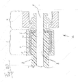
- Figure 1 shows a cross-sectional view of a hydraulic hose coupling 1, 2 according to the invention.
- the body of the coupling has an end 1 for inserting a hydraulic hose and an end 2 for coupling to another part of a hydraulic system.
- a cylindrical channel 3, 4 extends from the hose insertion end 1 to the coupling end 2.
- the first part of the cylindrical channel 3 is arranged in the hose insertion end 1 and the second part of the cylindrical channel 4 is arranged in the coupling end 2.
- the hose insertion end 1 has a recess 5 and a bore 6 connecting the recess 5 to the outer surface of the coupling.
- the first part of the channel 3 has diameter D 1 and the second part of the channel 4 has diameter D 2 and D 1 is larger than D 2 .
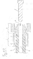
- Figures 2A - 2D show schematically different steps of an embodiment of a method according to the invention.
- Figure 2A shows a hydraulic hose 7 which has an outer diameter D 3 and the inside of the hose 8 has diameter D 4 , a coupling 1, 2 as depicted in Figure 1 and a mandrel 9 having diameter D 2 .
- the diameters D 1 and D 3 of the first part of the channel 3 respectively the hydraulic hose 7 correspond and the diameters D 2 and D 4 of the second part of the channel 4 and mandrel 9 respectively the inside of the hose 8 correspond.
- the hydraulic hose 7 is being inserted into the hose insertion end 1 in the shown step.
- Figure 2B shows the hose coupling 1, 2 with the hydraulic hose 7 inserted into the hose insertion end 1.
- the hydraulic hose 7 is inserted partially along the recess 5, leaving a space 10 between the end of the hydraulic hose 7 and the body of the coupling 1, 2.
- the mandrel 9 is inserted into the coupling end 2 in the shown step, sealing the inside of the hose 8 from the space 10 and the second part of the channel 4.
- Figure 2C shows the hose coupling 1, 2 with the hydraulic hose 7 inserted.
- the mandrel 9 is inserted into the second part of the channel 4.
- the mandrel 9 extends into the inside of the hydraulic hose 8 to seal the inside of the hydraulic hose 8 from the space 10 and thereby from the recess 5 as well.
- a bonding compound 11 is supplied to the recess 5 as well as to the space 10 through the bore 6 such that the recess 5 as well as the space 10 is filled.
- Figure 2D shows the obtained combination 12 comprising the hose coupling 1, 2 with the hydraulic hose 7 inserted and where the bonding compound 11 fills the recess 5 and the space 10.
- An unrestricted and continuous passage is formed by the inside of the hose 8, the bonding compound 11 in the space 10 and the second part of the channel 4.
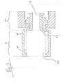
- Figure 3 shows a cross-sectional view of a second embodiment of a hose coupling 21, 22 according to the invention.
- the body of the coupling has an end 21 for inserting a hydraulic hose and an end 22 for coupling to another part of a hydraulic system.
- a cylindrical channel 23, 24 extends from the hose insertion end 21 to the coupling end 22.
- the first part of the cylindrical channel 23 is arranged in the hose insertion end 21 and the second part of the cylindrical channel 24 is arranged in the coupling end 22.
- the hose insertion end 21 has a recess 25 and a bore 26 connecting the recess 25 to the outer surface of the coupling.
- a protrusion 27 inside the first part of the channel 23 acts as a depth stop for a hose, ensuring proper insertion depth when a hydraulic hose is combined with the coupling 21, 22.
Landscapes
- Engineering & Computer Science (AREA)
- General Engineering & Computer Science (AREA)
- Mechanical Engineering (AREA)
- Non-Disconnectible Joints And Screw-Threaded Joints (AREA)
- Joints That Cut Off Fluids, And Hose Joints (AREA)
- Quick-Acting Or Multi-Walled Pipe Joints (AREA)
Abstract
Description
- The invention relates to a device for connecting a tubular element, such as a hose or pipe, to another part of a hydraulic or pneumatic system, which device comprises a body having a connection end and a tubular element insertion end, having a cylindrical channel extending from the connection end to the tubular element insertion end, where the connection end serves the purpose of connecting to another part of the hydraulic or pneumatic system, and wherein the cylindrical channel comprises a first part and a second part, wherein the first part is arranged in the tubular element insertion end and wherein the second part is arranged in the connection end.
- Typically hydraulic hose fittings are attached by crimping the fitting on the hose in order to create a hose assembly. The deformation of the hose fitting requires special crimping machines which need to apply a high mechanical force to the fitting. Obtaining a consistent deformation without introducing unwanted bending, cracking or fracture is difficult. The tightness of the seal obtained by the depression of the surface of the hose is furthermore determined by the extent to which a consistent depression across the entire circumference of the hose is achieved by the crimping action.
- The plastic deformation of the fitting through the crimping action, which is typically only path controlled, can easily result in vulnerabilities of the assembly through reduced wall thickness, fractures or unequal force distribution.
- The crimping machines used for attaching a crimp fitting to a hose require crimping dies that correspond with the type of fitting and its diameter. There are a lot of different combinations that need to be accounted for and a new combination of a hose and a fitting often requires a new set of dies as well. This is especially cumbersome in case a fitting needs to be replaced in the field, meaning that a lot of variants of tools have to be brought on site. Also getting proper access to a fitting with the required crimping machines may be rather tedious, especially when replacing a fitting in situ.
- Typical crimping hose fittings furthermore support the hose from the inside, in order to achieve a high clamping force between the fitting and the hose. This however introduces a reduction to the internal diameter which has a negative impact on flow characteristics such as for example causing an unwanted pressure drop across the assembly or causing turbulent flow and furthermore induces mechanical stress in the fitting.
- Today's fittings are mainly manufactured from metal, because of its great deformation properties which are required for crimping. Alternative materials such as composites like ultra strength polymers or polymer-metal matrices can not easily be applied, even though the alternative materials may introduce other benefits compared to metal.
- Attaching an end face structure to a tubular element by applying an adhesive is for example known from
WO2012008371 . - The passages between the reinforced hose and the sleeve are filled with an adhesive, but the passages are not sealed on the hose end. Forces applied to the hose thus have to be transferred to the sleeve via the adhesive on to the circumferential inner surface of the sleeve only. The force transfer between the adhesive and the sleeve is thus only dependent on the adhesive strength of the adhesive.
- It is an object of the invention to reduce or even remove the above mentioned disadvantages.
- This object is achieved according to the invention with a device according to the preamble, which is characterized in that the tubular element insertion end comprises at a middle section a recess extending radially from the cylindrical channel, along the entire circumference and which recess borders the second part of the cylindrical channel; and in that the tubular element insertion end comprises at least one bore connecting said recess with the outer surface of the body.
- By having the recess connected with the outer surface of the body, a means for introducing a bonding compound to the device is provided. This allows a tubular element to be retained by the fitting without crimping, achieving a sealed connection between the tubular element and the fitting through the bonding compound. Such connection can be achieved by simply inserting the tubular element into the tubular element insertion end, and by hermetically sealing the gap between the tubular element, the recess and the second part of the cylindrical channel, before supplying a bonding compound through a bore into the recess. The bonding compound then retains the tubular element and in the same time provides the seal between the tubular element and the device. Forces subjected to the hose are transferred via the bonding compound onto the sleeve both by adhesive strength as well as the shape defined connection of bounding compound and sleeve due to the cavity. This results in a stronger connection between the bonding compound and the sleeve.
- In a preferred embodiment of the device, the first part is of larger diameter than the second part of the cylindrical channel and wherein the first part and second part are concentric when viewed in axial direction of the cylindrical channel. By selecting the larger diameter to correspond with the outer diameter of the tubular element and the smaller diameter to correspond to the inner diameter of the tubular element, an assembly can be made which has no restrictions in the inner diameter. Furthermore, such an embodiment allows the tubular element to fully seal the recess. The reduced diameter also acts as a stop to indicate that the tubular element has been inserted sufficiently far.
- In another embodiment of the device according to the invention at least one protrusion is arranged in the first part of the cylindrical channel. The protrusion(s) can aid in the positioning of the tubular element in the fitting, so that assembly is simplified even more. The protrusion(s) can also act as a positioning aid, or more specifically a stop, so that the bonding compound can also reach the cut face of the tubular element.
- The invention also relates to a combination of a device according to the invention, a tubular element and a bonding compound, wherein the outer diameter of the tubular element corresponds with the inner diameter of the first part of the cylindrical channel and where the tubular element end extends into the middle section comprising the recess and where the recess is filled with a bonding compound.
- In another preferred embodiment of the combination according to the invention the inner diameter of the tubular element corresponds with the inner diameter of the second part of the cylindrical channel.
- The invention also relates to a method for connecting a device according to the invention with a tubular element, wherein the method comprises the steps of:
- providing a tubular element having a tubular channel;
- providing a device according to the invention;
- inserting the tubular element into the tubular element insertion end and at least partially along the recess;
- sealing the recess from the tubular channel and the second part of the cylindrical channel of the device;
- providing a bonding compound;
- filling the recess supplying the bonding compound via the at least one bore.
- With the method according to the invention, a fitting can be easily connected with a tubular element, taking the respective diameters to correspond and by applying the bonding compound to affix and seal connection between the tubular element and the device. The method involves no steps which include a high mechanical force and therefor does not necessitate machines to be used to make the connection. Sealing the tubular channel from the recess can be achieved by inserting a sealing body into the tubular channel or by abutting a sealing body to the annular surface on the end of the tubular element. Furthermore, by skiving the end of the tubular element, e.g. a reinforced hose, a surface can be exposed within the recess that improves the bond between the tubular element and the bonding compound.
- The bonding compound can as such also act as a viscoelastic barrier to provide damping and absorb vibrational forces.
- The fitting with the recess provides a chemically and mechanically stable setting for applying advanced adhesives or bonding compounds without requiring operators to supply further equipment. This means that operators do not require any specific expertise or equipment to make the combination.
- A further embodiment of the method according to the invention further comprises the steps of:
- providing a sealing body;
- inserting the sealing body into the cylindrical channel sealing the second part of the cylindrical channel;
- These and other features of the invention will be elucidated in conjunction with the accompanying drawings.
-
Figure 1 shows a cross-sectional view of a first embodiment of the device according to the invention. -
Figures 2A - 2D shows different steps of an embodiment of the method according to the invention. -
Figure 3 shows a cross-sectional view of a second embodiment of the device according to the invention. -
Figure 1 shows a cross-sectional view of ahydraulic hose coupling 1, 2 according to the invention. The body of the coupling has an end 1 for inserting a hydraulic hose and anend 2 for coupling to another part of a hydraulic system. Acylindrical channel coupling end 2. The first part of thecylindrical channel 3 is arranged in the hose insertion end 1 and the second part of thecylindrical channel 4 is arranged in thecoupling end 2. - The hose insertion end 1 has a recess 5 and a bore 6 connecting the recess 5 to the outer surface of the coupling.
- The first part of the
channel 3 has diameter D1 and the second part of thechannel 4 has diameter D2 and D1 is larger than D2. -
Figures 2A - 2D show schematically different steps of an embodiment of a method according to the invention. -
Figure 2A shows a hydraulic hose 7 which has an outer diameter D3 and the inside of thehose 8 has diameter D4, acoupling 1, 2 as depicted inFigure 1 and a mandrel 9 having diameter D2. The diameters D1 and D3 of the first part of thechannel 3 respectively the hydraulic hose 7 correspond and the diameters D2 and D4 of the second part of thechannel 4 and mandrel 9 respectively the inside of thehose 8 correspond. - The hydraulic hose 7 is being inserted into the hose insertion end 1 in the shown step.
-
Figure 2B shows thehose coupling 1, 2 with the hydraulic hose 7 inserted into the hose insertion end 1. The hydraulic hose 7 is inserted partially along the recess 5, leaving aspace 10 between the end of the hydraulic hose 7 and the body of thecoupling 1, 2. - The mandrel 9 is inserted into the
coupling end 2 in the shown step, sealing the inside of thehose 8 from thespace 10 and the second part of thechannel 4. -
Figure 2C shows thehose coupling 1, 2 with the hydraulic hose 7 inserted. The mandrel 9 is inserted into the second part of thechannel 4. The mandrel 9 extends into the inside of thehydraulic hose 8 to seal the inside of thehydraulic hose 8 from thespace 10 and thereby from the recess 5 as well. A bonding compound 11 is supplied to the recess 5 as well as to thespace 10 through the bore 6 such that the recess 5 as well as thespace 10 is filled. - Finally, the mandrel 9 is removed in the shown step.
-
Figure 2D shows the obtainedcombination 12 comprising thehose coupling 1, 2 with the hydraulic hose 7 inserted and where the bonding compound 11 fills the recess 5 and thespace 10. An unrestricted and continuous passage is formed by the inside of thehose 8, the bonding compound 11 in thespace 10 and the second part of thechannel 4. -
Figure 3 shows a cross-sectional view of a second embodiment of ahose coupling end 21 for inserting a hydraulic hose and anend 22 for coupling to another part of a hydraulic system. Acylindrical channel hose insertion end 21 to thecoupling end 22. The first part of thecylindrical channel 23 is arranged in thehose insertion end 21 and the second part of thecylindrical channel 24 is arranged in thecoupling end 22. - The
hose insertion end 21 has arecess 25 and a bore 26 connecting therecess 25 to the outer surface of the coupling. - A
protrusion 27 inside the first part of thechannel 23 acts as a depth stop for a hose, ensuring proper insertion depth when a hydraulic hose is combined with thecoupling - It will be clear to the person skilled in the art, that the second embodiment of the
hose coupling hose coupling 1, 2 as shown infigures 1 ,2A - 2D .
Claims (8)
- Device (1, 2; 21, 22) for connecting a tubular element (7), such as a hose or pipe, to another part of a hydraulic or pneumatic system, which device (1, 2; 21, 22) comprises a body having a connection end (2; 22) and a tubular element insertion end (1; 21), having a cylindrical channel (3, 4; 23, 24) extending from the connection end (2; 22) to the tubular element insertion end (1; 21), where the connection end (2; 22) serves the purpose of connecting to another part of the hydraulic or pneumatic system, and wherein the cylindrical channel (3, 4; 23, 24) comprises a first part (3; 23) and a second part (4; 24), wherein the first part (3; 23) is arranged in the tubular element insertion end (1; 21) and wherein the second part (4; 24) is arranged in the connection end (2; 22),
characterized in that
the tubular element insertion end (1; 21) comprises at a middle section a recess (5; 25) extending radially from the first part of the cylindrical channel (3; 23), along the entire circumference and which recess (5; 25) borders the second part of the cylindrical channel (4; 24); and
in that the tubular element insertion end (1; 21) comprises at least one bore (6; 26) connecting said recess (5; 25) with the outer surface of the body. - Device (1, 2; 21, 22) according to claim , characterized in that the first part (3; 23) is of larger diameter than the second part (4; 24) of the cylindrical channel (3, 4; 23; 24) and wherein the first part (3; 23) and second part (4; 24) are concentric when viewed in axial direction of the cylindrical channel (3, 4; 23, 24).
- Device (21,22) according to claim , characterized in that at least one protrusion (27) is arranged in the first part of the cylindrical channel (23).
- A combination (12) of a device (1, 2; 21, 22) according to any of the claims - , a tubular element (7) and a bonding compound (11), wherein the outer diameter (D3) of the tubular element (7) corresponds with the inner diameter (D1) of the first part of the cylindrical channel (3; 23) and where the tubular element (7) end extends into the middle section comprising the recess (5; 25) and where the recess (5; 25) is filled with a bonding compound (11).
- A combination (12) according to claim where the inner diameter (D4) of the tubular element (7) corresponds with the inner diameter (D2) of the second part of the cylindrical channel (4; 24).
- Method for connecting a device (1,2; 21, 22) according to the invention with a tubular element (7), wherein the method comprises the steps of:- providing a tubular element (7) having a tubular channel (8);- providing a device (1,2; 21, 22) according to any of the claims - ;- inserting the tubular element (7) into the tubular element insertion end (1; 21) and at least partially along the recess (5; 25);- sealing the recess (5; 25) from the tubular channel (8) and the second part (4; 24) of the cylindrical channel of the device (1,2; 21, 22);- providing a bonding compound (11);- filling the recess (5; 25) supplying the bonding compound (11) via the at least one bore (6; 26).
- Method according to claim , wherein the recess (5; 25) is sealed by inserting the tubular element (7) at least up to the second part of the cylindrical channel (4; 24) .
- Method according to claim , further comprising the steps of:- providing a sealing body (9);- inserting the sealing body (9) into the cylindrical channel (3, 4; 23, 24) sealing the second part (4; 24) of the cylindrical channel;
wherein the sealing body (9) is inserted partially into the tubular channel (8) to seal the tubular channel (8) from the recess (5; 25);- after filling the recess (5; 25) with the bonding compound (11), removing the sealing body (9) from the second part (4; 24) of the cylindrical channel.
Applications Claiming Priority (1)
| Application Number | Priority Date | Filing Date | Title |
|---|---|---|---|
| GB1901014.9A GB2580693B (en) | 2019-01-25 | 2019-01-25 | Device for connecting a tubular element, a combination of a device with a tubular element and a bonding compound, as well as a method for connecting the |
Publications (2)
| Publication Number | Publication Date |
|---|---|
| EP3686469A1 true EP3686469A1 (en) | 2020-07-29 |
| EP3686469B1 EP3686469B1 (en) | 2021-12-22 |
Family
ID=65656019
Family Applications (1)
| Application Number | Title | Priority Date | Filing Date |
|---|---|---|---|
| EP20153284.3A Active EP3686469B1 (en) | 2019-01-25 | 2020-01-23 | A method for connecting a device with a tubular element |
Country Status (6)
| Country | Link |
|---|---|
| US (1) | US11435017B2 (en) |
| EP (1) | EP3686469B1 (en) |
| CN (1) | CN111486288B (en) |
| DK (1) | DK3686469T3 (en) |
| ES (1) | ES2912735T3 (en) |
| GB (1) | GB2580693B (en) |
Citations (6)
| Publication number | Priority date | Publication date | Assignee | Title |
|---|---|---|---|---|
| US3916502A (en) * | 1971-09-17 | 1975-11-04 | Luigi Bagnulo | Method of establishing a pipe joint |
| GB2159902A (en) * | 1984-06-07 | 1985-12-11 | British Gas Corp | Sealing pipe joints |
| US4605466A (en) * | 1980-11-28 | 1986-08-12 | The Goodyear Tire & Rubber Company | Hose coupling method |
| WO2012008371A1 (en) | 2010-07-13 | 2012-01-19 | 株式会社トヨックス | End face structure of reinforced hose and method for treating end face of hose, and coating cap |
| US20120043752A1 (en) * | 2004-03-24 | 2012-02-23 | Ips, Corporation - Weld-On Division | Pipe joints |
| US20130043676A1 (en) * | 2011-08-16 | 2013-02-21 | Newage Industries, Inc. | Overmolded seal for barbed tubing connection |
Family Cites Families (13)
| Publication number | Priority date | Publication date | Assignee | Title |
|---|---|---|---|---|
| US2920910A (en) * | 1955-12-14 | 1960-01-12 | Resistoflex Corp | Reinforced hose end fittings |
| US3051511A (en) * | 1958-07-14 | 1962-08-28 | Thomas L Fawick | Hose coupling having fluid pressure balancing means |
| DE1902520A1 (en) * | 1969-01-18 | 1970-08-06 | Harald Krakar | Fittings for pipe connections |
| US4647080A (en) * | 1985-02-04 | 1987-03-03 | Price Brothers Company | Pipe joint |
| US4927999A (en) * | 1986-10-14 | 1990-05-22 | Georg Fischer Ag | Apparatus for fusion joining plastic pipe |
| DE19945541C1 (en) * | 1999-09-23 | 2001-07-26 | Parker Hannifin Gmbh | Method to fix nipple insert to hose having reinforcement inlay involves pressing sleeve over hose body on reinforcement inlay and arranging precrimped ring between hose and sleeve to engage inlay |
| JP4227045B2 (en) * | 2004-03-10 | 2009-02-18 | 三菱電機株式会社 | Tubular member joining method and tubular member joining structure |
| CN101016967A (en) * | 2006-11-21 | 2007-08-15 | 阎金波 | Thin-walled stainless steel tube sealing, sticking and fastening connection method |
| CN201237048Y (en) * | 2008-05-22 | 2009-05-13 | 何永水 | Soldering type stainless steel bellows used for water system air conditioner |
| US8757672B2 (en) * | 2009-08-19 | 2014-06-24 | Ipex Technologies, Inc. | Pipe fitting with a solvent cement barrier |
| FR2949529B1 (en) * | 2009-08-27 | 2015-04-24 | Coutier Moulage Gen Ind | SEALING DEVICE FOR CONNECTION BETWEEN A METALLIC TUBULAR ELEMENT AND A TUBULAR ELEMENT PRODUCED IN SYNTHETIC MATERIAL |
| GB2521612A (en) * | 2013-12-23 | 2015-07-01 | Eaton Ind Ip Gmbh & Co Kg | Hose connection |
| CN105605354A (en) * | 2016-01-26 | 2016-05-25 | 华尔达(厦门)塑胶有限公司 | Pipe fitting connecting structure and manufacturing method thereof |
-
2019
- 2019-01-25 GB GB1901014.9A patent/GB2580693B/en active Active
-
2020
- 2020-01-22 CN CN202010076076.8A patent/CN111486288B/en active Active
- 2020-01-23 EP EP20153284.3A patent/EP3686469B1/en active Active
- 2020-01-23 ES ES20153284T patent/ES2912735T3/en active Active
- 2020-01-23 DK DK20153284.3T patent/DK3686469T3/en active
- 2020-01-24 US US16/751,210 patent/US11435017B2/en active Active
Patent Citations (6)
| Publication number | Priority date | Publication date | Assignee | Title |
|---|---|---|---|---|
| US3916502A (en) * | 1971-09-17 | 1975-11-04 | Luigi Bagnulo | Method of establishing a pipe joint |
| US4605466A (en) * | 1980-11-28 | 1986-08-12 | The Goodyear Tire & Rubber Company | Hose coupling method |
| GB2159902A (en) * | 1984-06-07 | 1985-12-11 | British Gas Corp | Sealing pipe joints |
| US20120043752A1 (en) * | 2004-03-24 | 2012-02-23 | Ips, Corporation - Weld-On Division | Pipe joints |
| WO2012008371A1 (en) | 2010-07-13 | 2012-01-19 | 株式会社トヨックス | End face structure of reinforced hose and method for treating end face of hose, and coating cap |
| US20130043676A1 (en) * | 2011-08-16 | 2013-02-21 | Newage Industries, Inc. | Overmolded seal for barbed tubing connection |
Also Published As
| Publication number | Publication date |
|---|---|
| DK3686469T3 (en) | 2022-03-21 |
| GB2580693B (en) | 2023-03-15 |
| US11435017B2 (en) | 2022-09-06 |
| ES2912735T3 (en) | 2022-05-27 |
| US20200240562A1 (en) | 2020-07-30 |
| GB2580693A (en) | 2020-07-29 |
| CN111486288B (en) | 2022-08-19 |
| EP3686469B1 (en) | 2021-12-22 |
| GB201901014D0 (en) | 2019-03-13 |
| CN111486288A (en) | 2020-08-04 |
Similar Documents
| Publication | Publication Date | Title |
|---|---|---|
| US20240076950A1 (en) | Punch and inject tool for downhole casing and method for use thereof | |
| US11603951B2 (en) | Pinned composite pipe end-fitting | |
| CN1086784C (en) | Expandable pin plug for automated use | |
| FI91102C (en) | Method for performing a leak-free joint in a rigid pipe | |
| CN1138081C (en) | Pipe joint and connecting method thereof | |
| US7722085B2 (en) | Undersea pipe including an internal liner | |
| CZ26899A3 (en) | Tubular joint | |
| CA2645212A1 (en) | Connection between a lateral and main pipe and method for making same remotely | |
| CN103442822A (en) | Method and set of components for producing a tubular structural part, in particular a built-up camshaft | |
| EP3686469B1 (en) | A method for connecting a device with a tubular element | |
| TWI331115B (en) | Systems adapted to cooperate with an aperture forming tool and methods | |
| US8919822B2 (en) | Fitting system for a hydraulic tuning cable | |
| CN111963802B (en) | Hose connector, hose line and method for producing a hose connector | |
| US10343877B2 (en) | Component for replacing pipes, method of use, and kit of parts for use in removing pipes | |
| EP1321704A2 (en) | End fitting for tubular members and method of applying same | |
| CN109891206B (en) | Method of producing a pressure transmitter system | |
| JP4721848B2 (en) | Expansion anchor for pinning method and pinning method using the same | |
| US9752709B2 (en) | Hydraulic fitting insert | |
| EP4119831B1 (en) | Pipeline sanitation system and method for repairing a pipeline | |
| EP0843120A1 (en) | Method for securing a fitting to a hose and hose assembly obtained by such a method | |
| JP2004132431A (en) | Sealing method and structure of oil / hydraulic piping system opening | |
| GB2314904A (en) | Expandable sealing plug assembly for pipe wall opening and method using such | |
| US20120126482A1 (en) | Tube sealing device and a sealing element for such a device | |
| CN102481615B (en) | Method for obtaining openings in a hollow body component and hollow body component provided with one or more openings obtained using said method | |
| SU1409401A1 (en) | Method of rivetting parts made of fibrous composite materials |
Legal Events
| Date | Code | Title | Description |
|---|---|---|---|
| PUAI | Public reference made under article 153(3) epc to a published international application that has entered the european phase |
Free format text: ORIGINAL CODE: 0009012 |
|
| STAA | Information on the status of an ep patent application or granted ep patent |
Free format text: STATUS: THE APPLICATION HAS BEEN PUBLISHED |
|
| AK | Designated contracting states |
Kind code of ref document: A1 Designated state(s): AL AT BE BG CH CY CZ DE DK EE ES FI FR GB GR HR HU IE IS IT LI LT LU LV MC MK MT NL NO PL PT RO RS SE SI SK SM TR |
|
| AX | Request for extension of the european patent |
Extension state: BA ME |
|
| STAA | Information on the status of an ep patent application or granted ep patent |
Free format text: STATUS: REQUEST FOR EXAMINATION WAS MADE |
|
| 17P | Request for examination filed |
Effective date: 20210129 |
|
| RBV | Designated contracting states (corrected) |
Designated state(s): AL AT BE BG CH CY CZ DE DK EE ES FI FR GB GR HR HU IE IS IT LI LT LU LV MC MK MT NL NO PL PT RO RS SE SI SK SM TR |
|
| GRAP | Despatch of communication of intention to grant a patent |
Free format text: ORIGINAL CODE: EPIDOSNIGR1 |
|
| STAA | Information on the status of an ep patent application or granted ep patent |
Free format text: STATUS: GRANT OF PATENT IS INTENDED |
|
| RIC1 | Information provided on ipc code assigned before grant |
Ipc: F16L 33/32 20060101AFI20210608BHEP Ipc: F16L 33/34 20060101ALI20210608BHEP Ipc: B29C 65/48 20060101ALI20210608BHEP |
|
| INTG | Intention to grant announced |
Effective date: 20210701 |
|
| RIN1 | Information on inventor provided before grant (corrected) |
Inventor name: DONMEZ, HASAN BARCA Inventor name: APTIOGULLARI, ERHAN Inventor name: KARAYAGIZ, SALIH Inventor name: MUCO, RECEP |
|
| GRAS | Grant fee paid |
Free format text: ORIGINAL CODE: EPIDOSNIGR3 |
|
| GRAA | (expected) grant |
Free format text: ORIGINAL CODE: 0009210 |
|
| STAA | Information on the status of an ep patent application or granted ep patent |
Free format text: STATUS: THE PATENT HAS BEEN GRANTED |
|
| AK | Designated contracting states |
Kind code of ref document: B1 Designated state(s): AL AT BE BG CH CY CZ DE DK EE ES FI FR GB GR HR HU IE IS IT LI LT LU LV MC MK MT NL NO PL PT RO RS SE SI SK SM TR |
|
| REG | Reference to a national code |
Ref country code: GB Ref legal event code: FG4D |
|
| REG | Reference to a national code |
Ref country code: CH Ref legal event code: EP |
|
| REG | Reference to a national code |
Ref country code: DE Ref legal event code: R096 Ref document number: 602020001314 Country of ref document: DE |
|
| REG | Reference to a national code |
Ref country code: AT Ref legal event code: REF Ref document number: 1457288 Country of ref document: AT Kind code of ref document: T Effective date: 20220115 |
|
| REG | Reference to a national code |
Ref country code: IE Ref legal event code: FG4D |
|
| REG | Reference to a national code |
Ref country code: DK Ref legal event code: T3 Effective date: 20220317 |
|
| REG | Reference to a national code |
Ref country code: LT Ref legal event code: MG9D |
|
| PG25 | Lapsed in a contracting state [announced via postgrant information from national office to epo] |
Ref country code: RS Free format text: LAPSE BECAUSE OF FAILURE TO SUBMIT A TRANSLATION OF THE DESCRIPTION OR TO PAY THE FEE WITHIN THE PRESCRIBED TIME-LIMIT Effective date: 20211222 Ref country code: LT Free format text: LAPSE BECAUSE OF FAILURE TO SUBMIT A TRANSLATION OF THE DESCRIPTION OR TO PAY THE FEE WITHIN THE PRESCRIBED TIME-LIMIT Effective date: 20211222 Ref country code: FI Free format text: LAPSE BECAUSE OF FAILURE TO SUBMIT A TRANSLATION OF THE DESCRIPTION OR TO PAY THE FEE WITHIN THE PRESCRIBED TIME-LIMIT Effective date: 20211222 Ref country code: BG Free format text: LAPSE BECAUSE OF FAILURE TO SUBMIT A TRANSLATION OF THE DESCRIPTION OR TO PAY THE FEE WITHIN THE PRESCRIBED TIME-LIMIT Effective date: 20220322 |
|
| REG | Reference to a national code |
Ref country code: NL Ref legal event code: MP Effective date: 20211222 |
|
| REG | Reference to a national code |
Ref country code: AT Ref legal event code: MK05 Ref document number: 1457288 Country of ref document: AT Kind code of ref document: T Effective date: 20211222 |
|
| PG25 | Lapsed in a contracting state [announced via postgrant information from national office to epo] |
Ref country code: SE Free format text: LAPSE BECAUSE OF FAILURE TO SUBMIT A TRANSLATION OF THE DESCRIPTION OR TO PAY THE FEE WITHIN THE PRESCRIBED TIME-LIMIT Effective date: 20211222 Ref country code: NO Free format text: LAPSE BECAUSE OF FAILURE TO SUBMIT A TRANSLATION OF THE DESCRIPTION OR TO PAY THE FEE WITHIN THE PRESCRIBED TIME-LIMIT Effective date: 20220322 Ref country code: LV Free format text: LAPSE BECAUSE OF FAILURE TO SUBMIT A TRANSLATION OF THE DESCRIPTION OR TO PAY THE FEE WITHIN THE PRESCRIBED TIME-LIMIT Effective date: 20211222 Ref country code: HR Free format text: LAPSE BECAUSE OF FAILURE TO SUBMIT A TRANSLATION OF THE DESCRIPTION OR TO PAY THE FEE WITHIN THE PRESCRIBED TIME-LIMIT Effective date: 20211222 Ref country code: GR Free format text: LAPSE BECAUSE OF FAILURE TO SUBMIT A TRANSLATION OF THE DESCRIPTION OR TO PAY THE FEE WITHIN THE PRESCRIBED TIME-LIMIT Effective date: 20220323 |
|
| REG | Reference to a national code |
Ref country code: ES Ref legal event code: PC2A Owner name: DANFOSS POWER SOLUTIONS II TECHNOLOGY A/S Effective date: 20220621 |
|
| RAP2 | Party data changed (patent owner data changed or rights of a patent transferred) |
Owner name: DANFOSS POWER SOLUTIONS II TECHNOLOGY A/S |
|
| PG25 | Lapsed in a contracting state [announced via postgrant information from national office to epo] |
Ref country code: NL Free format text: LAPSE BECAUSE OF FAILURE TO SUBMIT A TRANSLATION OF THE DESCRIPTION OR TO PAY THE FEE WITHIN THE PRESCRIBED TIME-LIMIT Effective date: 20211222 |
|
| PG25 | Lapsed in a contracting state [announced via postgrant information from national office to epo] |
Ref country code: SM Free format text: LAPSE BECAUSE OF FAILURE TO SUBMIT A TRANSLATION OF THE DESCRIPTION OR TO PAY THE FEE WITHIN THE PRESCRIBED TIME-LIMIT Effective date: 20211222 Ref country code: SK Free format text: LAPSE BECAUSE OF FAILURE TO SUBMIT A TRANSLATION OF THE DESCRIPTION OR TO PAY THE FEE WITHIN THE PRESCRIBED TIME-LIMIT Effective date: 20211222 Ref country code: RO Free format text: LAPSE BECAUSE OF FAILURE TO SUBMIT A TRANSLATION OF THE DESCRIPTION OR TO PAY THE FEE WITHIN THE PRESCRIBED TIME-LIMIT Effective date: 20211222 Ref country code: PT Free format text: LAPSE BECAUSE OF FAILURE TO SUBMIT A TRANSLATION OF THE DESCRIPTION OR TO PAY THE FEE WITHIN THE PRESCRIBED TIME-LIMIT Effective date: 20220422 Ref country code: EE Free format text: LAPSE BECAUSE OF FAILURE TO SUBMIT A TRANSLATION OF THE DESCRIPTION OR TO PAY THE FEE WITHIN THE PRESCRIBED TIME-LIMIT Effective date: 20211222 Ref country code: CZ Free format text: LAPSE BECAUSE OF FAILURE TO SUBMIT A TRANSLATION OF THE DESCRIPTION OR TO PAY THE FEE WITHIN THE PRESCRIBED TIME-LIMIT Effective date: 20211222 |
|
| REG | Reference to a national code |
Ref country code: DE Ref legal event code: R081 Ref document number: 602020001314 Country of ref document: DE Owner name: DANFOSS POWER SOLUTIONS II TECHNOLOGY A/S, DK Free format text: FORMER OWNER: EATON INTELLIGENT POWER LIMITED, DUBLIN, IE Ref country code: DE Ref legal event code: R081 Ref document number: 602020001314 Country of ref document: DE Owner name: DANFOSS A/S, DK Free format text: FORMER OWNER: EATON INTELLIGENT POWER LIMITED, DUBLIN, IE |
|
| PG25 | Lapsed in a contracting state [announced via postgrant information from national office to epo] |
Ref country code: PL Free format text: LAPSE BECAUSE OF FAILURE TO SUBMIT A TRANSLATION OF THE DESCRIPTION OR TO PAY THE FEE WITHIN THE PRESCRIBED TIME-LIMIT Effective date: 20211222 Ref country code: AT Free format text: LAPSE BECAUSE OF FAILURE TO SUBMIT A TRANSLATION OF THE DESCRIPTION OR TO PAY THE FEE WITHIN THE PRESCRIBED TIME-LIMIT Effective date: 20211222 |
|
| REG | Reference to a national code |
Ref country code: DE Ref legal event code: R097 Ref document number: 602020001314 Country of ref document: DE |
|
| PG25 | Lapsed in a contracting state [announced via postgrant information from national office to epo] |
Ref country code: MC Free format text: LAPSE BECAUSE OF FAILURE TO SUBMIT A TRANSLATION OF THE DESCRIPTION OR TO PAY THE FEE WITHIN THE PRESCRIBED TIME-LIMIT Effective date: 20211222 Ref country code: IS Free format text: LAPSE BECAUSE OF FAILURE TO SUBMIT A TRANSLATION OF THE DESCRIPTION OR TO PAY THE FEE WITHIN THE PRESCRIBED TIME-LIMIT Effective date: 20220422 |
|
| REG | Reference to a national code |
Ref country code: BE Ref legal event code: MM Effective date: 20220131 |
|
| PLBE | No opposition filed within time limit |
Free format text: ORIGINAL CODE: 0009261 |
|
| STAA | Information on the status of an ep patent application or granted ep patent |
Free format text: STATUS: NO OPPOSITION FILED WITHIN TIME LIMIT |
|
| PG25 | Lapsed in a contracting state [announced via postgrant information from national office to epo] |
Ref country code: LU Free format text: LAPSE BECAUSE OF NON-PAYMENT OF DUE FEES Effective date: 20220123 Ref country code: AL Free format text: LAPSE BECAUSE OF FAILURE TO SUBMIT A TRANSLATION OF THE DESCRIPTION OR TO PAY THE FEE WITHIN THE PRESCRIBED TIME-LIMIT Effective date: 20211222 |
|
| 26N | No opposition filed |
Effective date: 20220923 |
|
| PG25 | Lapsed in a contracting state [announced via postgrant information from national office to epo] |
Ref country code: BE Free format text: LAPSE BECAUSE OF NON-PAYMENT OF DUE FEES Effective date: 20220131 |
|
| PG25 | Lapsed in a contracting state [announced via postgrant information from national office to epo] |
Ref country code: IE Free format text: LAPSE BECAUSE OF NON-PAYMENT OF DUE FEES Effective date: 20220123 |
|
| PG25 | Lapsed in a contracting state [announced via postgrant information from national office to epo] |
Ref country code: SI Free format text: LAPSE BECAUSE OF FAILURE TO SUBMIT A TRANSLATION OF THE DESCRIPTION OR TO PAY THE FEE WITHIN THE PRESCRIBED TIME-LIMIT Effective date: 20211222 |
|
| P01 | Opt-out of the competence of the unified patent court (upc) registered |
Effective date: 20230617 |
|
| REG | Reference to a national code |
Ref country code: CH Ref legal event code: PL |
|
| PG25 | Lapsed in a contracting state [announced via postgrant information from national office to epo] |
Ref country code: LI Free format text: LAPSE BECAUSE OF NON-PAYMENT OF DUE FEES Effective date: 20230131 Ref country code: CH Free format text: LAPSE BECAUSE OF NON-PAYMENT OF DUE FEES Effective date: 20230131 |
|
| REG | Reference to a national code |
Ref country code: ES Ref legal event code: PC2A Owner name: DANFOSS A/S Effective date: 20240416 |
|
| PG25 | Lapsed in a contracting state [announced via postgrant information from national office to epo] |
Ref country code: MK Free format text: LAPSE BECAUSE OF FAILURE TO SUBMIT A TRANSLATION OF THE DESCRIPTION OR TO PAY THE FEE WITHIN THE PRESCRIBED TIME-LIMIT Effective date: 20211222 Ref country code: CY Free format text: LAPSE BECAUSE OF FAILURE TO SUBMIT A TRANSLATION OF THE DESCRIPTION OR TO PAY THE FEE WITHIN THE PRESCRIBED TIME-LIMIT Effective date: 20211222 |
|
| PG25 | Lapsed in a contracting state [announced via postgrant information from national office to epo] |
Ref country code: HU Free format text: LAPSE BECAUSE OF FAILURE TO SUBMIT A TRANSLATION OF THE DESCRIPTION OR TO PAY THE FEE WITHIN THE PRESCRIBED TIME-LIMIT; INVALID AB INITIO Effective date: 20200123 |
|
| PG25 | Lapsed in a contracting state [announced via postgrant information from national office to epo] |
Ref country code: TR Free format text: LAPSE BECAUSE OF FAILURE TO SUBMIT A TRANSLATION OF THE DESCRIPTION OR TO PAY THE FEE WITHIN THE PRESCRIBED TIME-LIMIT Effective date: 20211222 |
|
| GBPC | Gb: european patent ceased through non-payment of renewal fee |
Effective date: 20240123 |
|
| PG25 | Lapsed in a contracting state [announced via postgrant information from national office to epo] |
Ref country code: MT Free format text: LAPSE BECAUSE OF FAILURE TO SUBMIT A TRANSLATION OF THE DESCRIPTION OR TO PAY THE FEE WITHIN THE PRESCRIBED TIME-LIMIT Effective date: 20211222 |
|
| PG25 | Lapsed in a contracting state [announced via postgrant information from national office to epo] |
Ref country code: GB Free format text: LAPSE BECAUSE OF NON-PAYMENT OF DUE FEES Effective date: 20240123 |
|
| PG25 | Lapsed in a contracting state [announced via postgrant information from national office to epo] |
Ref country code: GB Free format text: LAPSE BECAUSE OF NON-PAYMENT OF DUE FEES Effective date: 20240123 |
|
| REG | Reference to a national code |
Ref country code: DE Ref legal event code: R081 Ref document number: 602020001314 Country of ref document: DE Owner name: DANFOSS A/S, DK Free format text: FORMER OWNER: DANFOSS POWER SOLUTIONS II TECHNOLOGY A/S, NORDBORG, DK |
|
| PGFP | Annual fee paid to national office [announced via postgrant information from national office to epo] |
Ref country code: FR Payment date: 20251222 Year of fee payment: 7 |
|
| PGFP | Annual fee paid to national office [announced via postgrant information from national office to epo] |
Ref country code: ES Payment date: 20260212 Year of fee payment: 7 |
|
| PGFP | Annual fee paid to national office [announced via postgrant information from national office to epo] |
Ref country code: DK Payment date: 20260113 Year of fee payment: 7 Ref country code: DE Payment date: 20251203 Year of fee payment: 7 |
|
| PGFP | Annual fee paid to national office [announced via postgrant information from national office to epo] |
Ref country code: IT Payment date: 20251219 Year of fee payment: 7 |