EP3686459A1 - Pulley stopper and pulley device including same - Google Patents
Pulley stopper and pulley device including same Download PDFInfo
- Publication number
- EP3686459A1 EP3686459A1 EP19870062.7A EP19870062A EP3686459A1 EP 3686459 A1 EP3686459 A1 EP 3686459A1 EP 19870062 A EP19870062 A EP 19870062A EP 3686459 A1 EP3686459 A1 EP 3686459A1
- Authority
- EP
- European Patent Office
- Prior art keywords
- fastener
- clamp
- pulley
- stopper
- pulley stopper
- Prior art date
- Legal status (The legal status is an assumption and is not a legal conclusion. Google has not performed a legal analysis and makes no representation as to the accuracy of the status listed.)
- Granted
Links
Images




Classifications
-
- F—MECHANICAL ENGINEERING; LIGHTING; HEATING; WEAPONS; BLASTING
- F16—ENGINEERING ELEMENTS AND UNITS; GENERAL MEASURES FOR PRODUCING AND MAINTAINING EFFECTIVE FUNCTIONING OF MACHINES OR INSTALLATIONS; THERMAL INSULATION IN GENERAL
- F16H—GEARING
- F16H7/00—Gearings for conveying rotary motion by endless flexible members
- F16H7/08—Means for varying tension of belts, ropes or chains
-
- F—MECHANICAL ENGINEERING; LIGHTING; HEATING; WEAPONS; BLASTING
- F16—ENGINEERING ELEMENTS AND UNITS; GENERAL MEASURES FOR PRODUCING AND MAINTAINING EFFECTIVE FUNCTIONING OF MACHINES OR INSTALLATIONS; THERMAL INSULATION IN GENERAL
- F16H—GEARING
- F16H7/00—Gearings for conveying rotary motion by endless flexible members
- F16H7/02—Gearings for conveying rotary motion by endless flexible members with belts; with V-belts
-
- F—MECHANICAL ENGINEERING; LIGHTING; HEATING; WEAPONS; BLASTING
- F16—ENGINEERING ELEMENTS AND UNITS; GENERAL MEASURES FOR PRODUCING AND MAINTAINING EFFECTIVE FUNCTIONING OF MACHINES OR INSTALLATIONS; THERMAL INSULATION IN GENERAL
- F16H—GEARING
- F16H7/00—Gearings for conveying rotary motion by endless flexible members
- F16H7/18—Means for guiding or supporting belts, ropes, or chains
- F16H7/20—Mountings for rollers or pulleys
-
- F—MECHANICAL ENGINEERING; LIGHTING; HEATING; WEAPONS; BLASTING
- F16—ENGINEERING ELEMENTS AND UNITS; GENERAL MEASURES FOR PRODUCING AND MAINTAINING EFFECTIVE FUNCTIONING OF MACHINES OR INSTALLATIONS; THERMAL INSULATION IN GENERAL
- F16H—GEARING
- F16H7/00—Gearings for conveying rotary motion by endless flexible members
- F16H7/24—Equipment for mounting belts, ropes, or chains
-
- B—PERFORMING OPERATIONS; TRANSPORTING
- B63—SHIPS OR OTHER WATERBORNE VESSELS; RELATED EQUIPMENT
- B63B—SHIPS OR OTHER WATERBORNE VESSELS; EQUIPMENT FOR SHIPPING
- B63B21/00—Tying-up; Shifting, towing, or pushing equipment; Anchoring
- B63B21/04—Fastening or guiding equipment for chains, ropes, hawsers, or the like
- B63B21/08—Clamping devices
-
- F—MECHANICAL ENGINEERING; LIGHTING; HEATING; WEAPONS; BLASTING
- F16—ENGINEERING ELEMENTS AND UNITS; GENERAL MEASURES FOR PRODUCING AND MAINTAINING EFFECTIVE FUNCTIONING OF MACHINES OR INSTALLATIONS; THERMAL INSULATION IN GENERAL
- F16H—GEARING
- F16H7/00—Gearings for conveying rotary motion by endless flexible members
- F16H7/08—Means for varying tension of belts, ropes or chains
- F16H2007/0842—Mounting or support of tensioner
-
- F—MECHANICAL ENGINEERING; LIGHTING; HEATING; WEAPONS; BLASTING
- F16—ENGINEERING ELEMENTS AND UNITS; GENERAL MEASURES FOR PRODUCING AND MAINTAINING EFFECTIVE FUNCTIONING OF MACHINES OR INSTALLATIONS; THERMAL INSULATION IN GENERAL
- F16H—GEARING
- F16H7/00—Gearings for conveying rotary motion by endless flexible members
- F16H7/08—Means for varying tension of belts, ropes or chains
- F16H2007/0846—Means for varying tension of belts, ropes or chains comprising a mechanical stopper
Definitions
- the present invention relates to a pulley stopper and a pulley apparatus including the same, and more particularly, it relates to a pulley stopper that stops movement of a belt, and a pulley apparatus including the same.
- a V-belt is a V-shaped belt made of cloth and rubber, which is used by wrapping it on a V-shaped pulley. After replacing or motoring a current V-belt, as a method for determining whether or not a device is normally barred, the pulley or the V-belt is barred by hand. That is the V-belt is manually barred.
- a problem such as an accident in which a body part such as a user's finger is caught between the pulley and the V-belt due to inertia of a facility, which is a weighted object, often occurs.
- Exemplary embodiments of the present invention have been made in an effort to solve the above-stated problems of the conventionally proposed methods, and thus the exemplary embodiments of the present invention provide a pulley stopper, and a pulley device including the same, to provide a highly versatile stopper for various types of pulleys and V-belts, and to facilitate the fastening operation of the stopper by simplifying the fastening process.
- a pulley stopper includes: a clamp portion that includes a bar-shaped upper clamp and a bar-shaped lower clamp; and fasteners that are respectively disposed at opposite ends of the clamp portion to couple the upper clamp and the lower clamp, wherein the fasteners and the clamp portion are coupled by using a clip-type method, and thus the upper clamp and the lower clamp are fixed side by side through the coupling of the fastener such that movement of a belt disposed between the upper clamp and the lower clamp is stopped.
- the lower clamp may include a pin coupling portion to which one end of the fastener is coupled by a pin-coupling method, and the other end of the fastener may be rotatable about a fixed axis of the pin coupling portion.
- a groove through which that fastener moves while the end of the fastener rotates may be formed in each side surface of the upper clamp and the lower clamp.
- the other end of the fastener may be coupled to the upper clamp through rotation of the nut of the fastener by a bolt-nut coupling method such that a gap between the upper clamp and the lower clamp that are disposed side by side may be adjusted.
- the pulley stopper may further include a washer provided in a portion where the nut of the fastener and the upper clamp contact each other.
- a material of the washer may be made of brass.
- a material of the bolt of the fastener may be monomer casting nylon (M/C nylon), PBC, and brass.
- the fastener may include: a first fastener that is disposed at one end of the clamp portion; and a second fastener that is disposed in parallel with the first fastener at the other end of the clamp portion.
- At least one of the first fastener and the second fastener may be formed as a clip-type.
- a material of the clamp portion may be monomer casting (M/C) nylon.
- a material of the clamp portion may be polyoxymethylene (POM).
- a pulley apparatus may include the above-described pulley stopper.
- a pulley stopper coupled by a clip method can be used to simplify a fastening process and facilitate a fastening operation of the stopper, and thus it is possible to increase versatility of the stopper.
- FIG. 1 is a front view of a pulley stopper according to an exemplary embodiment of the present invention
- FIG. 2 is a side view of the pulley stopper according to the exemplary embodiment of the present invention.
- a pulley stopper 10 includes a clamp portion 100 including bar-shaped upper and lower clamps 110 and 120, and fasteners 200 that are respectively disposed at opposite ends of the clamp portion 100 to combine the upper clamp 110 and the lower clamp 120.
- the fastener 200 and the clamp portion 100 are coupled by using a clip-type method, and a moving method of the fastener 200 using the clip-type method will be described in detail with reference to FIG. 3 .
- a pin coupling portion 250 to which one end of the fastener 200 is coupled by a pin-coupling method may be included in the lower clamp 120.
- grooves 130 through which the fastener 200 moves while the other end of the fastener 200 bars may be formed at each side surface of the upper clamp 110 and the lower clamp 120 as paths for movement of the fastener 200.
- Each groove 130 is a gap that is sufficient to allow bolts 230 of the fastener 200 to pass therethrough, which may serve as a moving passage of the bolts 230 and simultaneously hold the bolts 230.
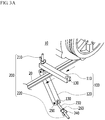
- FIG. 3A shows a state before coupling of the pulley stopper according to the exemplary embodiment of the present invention
- FIG. 3B shows a state after coupling of the pulley stopper according to the exemplary embodiment of the present invention.
- FIG. 3A shows a state of the fastener 200 removed from the groove 130 of the upper clamp 130, and thus a gap between the upper clamp 110 and the lower clamp 120 can be widened such that the belt 20 can move through the widened space.
- FIG. 3A shows a state of the fastener 200 removed from the groove 130 of the upper clamp 130, and thus a gap between the upper clamp 110 and the lower clamp 120 can be widened such that the belt 20 can move through the widened space.
- 3B shows a state of the fastener 200 inserted into the groove 130 of the upper clamp 110, and the upper clamp 110 and the lower clamp 120 are coupled side by side in a fixed manner with a narrow gap therebetween through the coupling of the fastening portion 200 such that movement of the belt 20 disposed between the upper clamp 110 and the lower clamp 120 can be stopped.
- the fastening portion 200 may include a first fastener 210 disposed at one end of the clamp portion 100, and a second fastener 220 that is disposed in parallel with the first fastener 210 at the other end of the clamp portion 100.
- the first fastener 210 and the second fastener 220 are both illustrated as a clip type, but this is not restrictive. Only one of the first fastener 210 and the second fastener 220 may be formed as the clip type. That is, at least one of the first fastener 210 and the second fastener 220 may be formed as the clip type.
- the clamp portion 200 coupled to the other fastener 200 which is not formed as the clip type, is in a state such that the groove 130 is not formed therein, and thus the fastener 200 may be fixed to the clamp portion 100 by being inserted therein.
- a material of the bolt 230 of the fastener 200 may be monomer casting nylon (M/C nylon), PBC, or brass, and a material of the clamp 100 may be M/C nylon, but this is not restrictive.
- the material of the clamp portion 100 may be polyoxymethylene (POMe), and may prevent damage to the pulley and the V belt 20 due to friction with the clamp portion 100.
- the other end of the fastener 200 has a bolt 230-nut 240 coupling, and the other end of the fastener 200 is coupled to the upper clamp 110 through rotation of the nut 240 of the fastener 200 such that the upper clamp 110 and the lower clamp 120 can be fixed side by side. That is, when the upper clamp 110 and the lower clamp 120 are disposed in parallel with each other, a gap between the upper clamp 110 and the lower clamp 120 can be adjusted through the rotation of the nut 240. As described, the belt 20 can be stopped by applying the pulley stopper 10 of the present invention to the belt 20 of various thicknesses by adjusting the gap between the upper clamp 110 and the lower clamp 120.
- the pulley stopper 10 may further include a washer 260 at a portion where the nut 240 of the fastener 200 and the upper clamp 110 contact each other. Since a ring-shaped washer 260 is disposed in a portion where the bolt 230 and the nut 240 are fixed, pressure applied to the corresponding portion can be dispersed, thereby protecting a working surface, and the waster 260 can increase a fastening effect of the bolt 230 and the nut 240.
- the washer 260 may be made of brass, but it is not restrictive.
- FIG. 4 shows a pulley apparatus where a pulley stopper is coupled thereto according to an exemplary embodiment of the present invention.
- a pulley apparatus 30 may include a pulley stopper 10 that includes a clamp portion that includes bar-shaped upper and lower clamps and fasteners that are respectively disposed at opposite ends of the clamp portion to couple the upper clamp and the lower clamp, and the fastener and the clamp portion are coupled as a clip type such that the upper clamp and the lower clamp are fixed side by side through the coupling of the fastener, thereby stopping movement of a belt 20 disposed between the upper clamp and the lower clamp.
- the present invention relates to a pulley stopper, which is intended to solve the problem of the conventional low versatility pulley device, and provides a highly versatile pulley stopper that can be used for various types of pulleys and V-belts, and simplifies a fastening process using a clip type of method such that a fastening process of the pulley stopper become easy.
Landscapes
- Engineering & Computer Science (AREA)
- General Engineering & Computer Science (AREA)
- Mechanical Engineering (AREA)
- Devices For Conveying Motion By Means Of Endless Flexible Members (AREA)
- Pulleys (AREA)
- Clamps And Clips (AREA)
Abstract
Description
- This application claims priority to and the benefit of Korean Patent Application No.
10-2018-0136600 - The present invention relates to a pulley stopper and a pulley apparatus including the same, and more particularly, it relates to a pulley stopper that stops movement of a belt, and a pulley apparatus including the same.
- A V-belt is a V-shaped belt made of cloth and rubber, which is used by wrapping it on a V-shaped pulley. After replacing or motoring a current V-belt, as a method for determining whether or not a device is normally barred, the pulley or the V-belt is barred by hand. That is the V-belt is manually barred. As described above, during the manual process, a problem such as an accident in which a body part such as a user's finger is caught between the pulley and the V-belt due to inertia of a facility, which is a weighted object, often occurs.
- For some pulleys, although manual barring equipment is in-house built and in use, since the pulley is very diverse in shape and size, there is no equipment that can be used universally. Further, in case of specific work requiring fixing of the pulley, a shaft of the pulley is fixed by using a pipe wrench or the like. However, in this case, a coating of the shaft is damaged, and the pulley and the V-belt may also be damaged.
- In the present invention, to alleviate the above problems, it is necessary to develop universal equipment that can fix pulleys of various sizes and shapes while minimizing damage to pulleys and V-belts.
- Exemplary embodiments of the present invention have been made in an effort to solve the above-stated problems of the conventionally proposed methods, and thus the exemplary embodiments of the present invention provide a pulley stopper, and a pulley device including the same, to provide a highly versatile stopper for various types of pulleys and V-belts, and to facilitate the fastening operation of the stopper by simplifying the fastening process.
- However, the problems to be solved by the exemplary embodiments of the present invention are not limited to the above-described problem, and can be variously extended in a range of technical ideas included in the present invention.
- A pulley stopper according to an exemplary embodiment of the present invention includes: a clamp portion that includes a bar-shaped upper clamp and a bar-shaped lower clamp; and fasteners that are respectively disposed at opposite ends of the clamp portion to couple the upper clamp and the lower clamp, wherein the fasteners and the clamp portion are coupled by using a clip-type method, and thus the upper clamp and the lower clamp are fixed side by side through the coupling of the fastener such that movement of a belt disposed between the upper clamp and the lower clamp is stopped.
- The lower clamp may include a pin coupling portion to which one end of the fastener is coupled by a pin-coupling method, and the other end of the fastener may be rotatable about a fixed axis of the pin coupling portion.
- A groove through which that fastener moves while the end of the fastener rotates may be formed in each side surface of the upper clamp and the lower clamp.
- The other end of the fastener may be coupled to the upper clamp through rotation of the nut of the fastener by a bolt-nut coupling method such that a gap between the upper clamp and the lower clamp that are disposed side by side may be adjusted.
- The pulley stopper may further include a washer provided in a portion where the nut of the fastener and the upper clamp contact each other.
- A material of the washer may be made of brass.
- A material of the bolt of the fastener may be monomer casting nylon (M/C nylon), PBC, and brass.
- The fastener may include: a first fastener that is disposed at one end of the clamp portion; and a second fastener that is disposed in parallel with the first fastener at the other end of the clamp portion.
- At least one of the first fastener and the second fastener may be formed as a clip-type.
- A material of the clamp portion may be monomer casting (M/C) nylon.
- A material of the clamp portion may be polyoxymethylene (POM).
- In addition, a pulley apparatus according to another exemplary embodiment of the present invention may include the above-described pulley stopper.
- According to exemplary embodiments of the present invention, a pulley stopper coupled by a clip method can be used to simplify a fastening process and facilitate a fastening operation of the stopper, and thus it is possible to increase versatility of the stopper.
-
-
FIG. 1 is a front view of a pulley stopper according to an exemplary embodiment of the present invent. -
FIG. 2 is a side view of the pulley stopper according to the exemplary embodiment of the present invention. -
FIG. 3A shows a state before coupling of the pulley stopper according to the exemplary embodiment of the present invention. -
FIG. 3B shows a state after coupling of the pulley stopper according to the exemplary embodiment of the present invention. -
FIG. 4 shows a pulley apparatus where a pulley stopper is coupled thereto according to an exemplary embodiment of the present invention. - In the following detailed description, only certain exemplary embodiments of the present invention have been shown and described, simply by way of illustration. As those skilled in the art would realize, the described embodiments may be modified in various different ways, all without departing from the spirit or scope of the present invention.
- Accordingly, the drawings and description are to be regarded as illustrative in nature and not restrictive. Like reference numerals designate like elements throughout the specification
- In addition, the size and thickness of each configuration shown in the drawing is arbitrarily shown for convenience of description, and therefore, the present invention is not necessarily limited to that shown. In the drawings, the thickness of layers, films, panels, regions, etc., are exaggerated for clarity. In the drawings, for convenience of explanation, the thicknesses of some layers and regions are exaggerated.
- It will be understood that when an element such as a layer, film, region, or substrate is referred to as being "on" another element, it can be directly on the other element or intervening elements may also be present. In contrast, when an element is referred to as being "directly on" another element, there are no intervening elements present. Further, throughout the specification, the word "on" means positioning on or below the object portion, but does not essentially mean positioning on the upper side of the object portion based on a gravitational direction.
- In addition, unless explicitly described to the contrary, the word "comprise" and variations such as "comprises" or "comprising" will be understood to imply the inclusion of stated elements but not the exclusion of any other elements.
-
FIG. 1 is a front view of a pulley stopper according to an exemplary embodiment of the present invention, andFIG. 2 is a side view of the pulley stopper according to the exemplary embodiment of the present invention. - As shown in
FIG. 1 andFIG. 2 , apulley stopper 10 according to an exemplary embodiment of the present invention includes aclamp portion 100 including bar-shaped upper andlower clamps fasteners 200 that are respectively disposed at opposite ends of theclamp portion 100 to combine theupper clamp 110 and thelower clamp 120. - The
fastener 200 and theclamp portion 100 are coupled by using a clip-type method, and a moving method of thefastener 200 using the clip-type method will be described in detail with reference toFIG. 3 . First, as a configuration for enabling thefastener 200 to move through a clip-type method as shown inFIG. 1 andFIG. 2 , apin coupling portion 250 to which one end of thefastener 200 is coupled by a pin-coupling method, may be included in thelower clamp 120. When thefastener 200 moves while rotating about thepin coupling portion 250 as an axis, grooves 130 through which thefastener 200 moves while the other end of thefastener 200 bars may be formed at each side surface of theupper clamp 110 and thelower clamp 120 as paths for movement of thefastener 200. Eachgroove 130 is a gap that is sufficient to allowbolts 230 of thefastener 200 to pass therethrough, which may serve as a moving passage of thebolts 230 and simultaneously hold thebolts 230. -
FIG. 3A shows a state before coupling of the pulley stopper according to the exemplary embodiment of the present invention, andFIG. 3B shows a state after coupling of the pulley stopper according to the exemplary embodiment of the present invention. - As shown in
FIG. 3A andFIG. 3B , the other end of thefastener 200 can rotate about a fixed axis of thepin coupling portion 250, and thus may be coupled in a manner of being inserted into and removed from thegroove 130 of theupper clamp 110.FIG. 3A shows a state of thefastener 200 removed from thegroove 130 of theupper clamp 130, and thus a gap between theupper clamp 110 and thelower clamp 120 can be widened such that thebelt 20 can move through the widened space.FIG. 3B shows a state of thefastener 200 inserted into thegroove 130 of theupper clamp 110, and theupper clamp 110 and thelower clamp 120 are coupled side by side in a fixed manner with a narrow gap therebetween through the coupling of thefastening portion 200 such that movement of thebelt 20 disposed between theupper clamp 110 and thelower clamp 120 can be stopped. - The
fastening portion 200 may include afirst fastener 210 disposed at one end of theclamp portion 100, and asecond fastener 220 that is disposed in parallel with thefirst fastener 210 at the other end of theclamp portion 100. InFIG. 1 to FIG. 3 , thefirst fastener 210 and thesecond fastener 220 are both illustrated as a clip type, but this is not restrictive. Only one of thefirst fastener 210 and thesecond fastener 220 may be formed as the clip type. That is, at least one of thefirst fastener 210 and thesecond fastener 220 may be formed as the clip type. In this case, theclamp portion 200 coupled to theother fastener 200, which is not formed as the clip type, is in a state such that thegroove 130 is not formed therein, and thus thefastener 200 may be fixed to theclamp portion 100 by being inserted therein. - A material of the
bolt 230 of thefastener 200 may be monomer casting nylon (M/C nylon), PBC, or brass, and a material of theclamp 100 may be M/C nylon, but this is not restrictive. Depending on exemplary embodiments, the material of theclamp portion 100 may be polyoxymethylene (POMe), and may prevent damage to the pulley and theV belt 20 due to friction with theclamp portion 100. - As shown in
FIG. 1 FIG. 3 , the other end of thefastener 200 has a bolt 230-nut 240 coupling, and the other end of thefastener 200 is coupled to theupper clamp 110 through rotation of thenut 240 of thefastener 200 such that theupper clamp 110 and thelower clamp 120 can be fixed side by side. That is, when theupper clamp 110 and thelower clamp 120 are disposed in parallel with each other, a gap between theupper clamp 110 and thelower clamp 120 can be adjusted through the rotation of thenut 240. As described, thebelt 20 can be stopped by applying thepulley stopper 10 of the present invention to thebelt 20 of various thicknesses by adjusting the gap between theupper clamp 110 and thelower clamp 120. - In addition, the
pulley stopper 10 may further include awasher 260 at a portion where thenut 240 of thefastener 200 and theupper clamp 110 contact each other. Since a ring-shapedwasher 260 is disposed in a portion where thebolt 230 and thenut 240 are fixed, pressure applied to the corresponding portion can be dispersed, thereby protecting a working surface, and thewaster 260 can increase a fastening effect of thebolt 230 and thenut 240. Thewasher 260 may be made of brass, but it is not restrictive. -
FIG. 4 shows a pulley apparatus where a pulley stopper is coupled thereto according to an exemplary embodiment of the present invention. - As shown in
FIG. 4 , apulley apparatus 30 according to an exemplary embodiment of the present invention may include apulley stopper 10 that includes a clamp portion that includes bar-shaped upper and lower clamps and fasteners that are respectively disposed at opposite ends of the clamp portion to couple the upper clamp and the lower clamp, and the fastener and the clamp portion are coupled as a clip type such that the upper clamp and the lower clamp are fixed side by side through the coupling of the fastener, thereby stopping movement of abelt 20 disposed between the upper clamp and the lower clamp. - As described above, the present invention relates to a pulley stopper, which is intended to solve the problem of the conventional low versatility pulley device, and provides a highly versatile pulley stopper that can be used for various types of pulleys and V-belts, and simplifies a fastening process using a clip type of method such that a fastening process of the pulley stopper become easy.
- While this invention has been described in connection with what is presently considered to be practical exemplary embodiments, it is to be understood that the invention is not limited to the disclosed embodiments. On the contrary, it is intended to cover various modifications and equivalent arrangements included within the spirit and scope of the appended claims.
-
- 10:
- pulley stopper
- 20:
- belt
- 30:
- pulley apparatus
- 100:
- clamp portion
- 110:
- upper clamp
- 120:
- lower clamp
- 130:
- groove
- 200:
- fastener
- 210:
- first fastener
- 220:
- second fastener
- 230:
- bolt
- 240:
- nut
- 250:
- pin coupling portion
- 260:
- washer
Claims (12)
- A pulley stopper comprising:a clamp portion that includes a bar-shaped upper clamp and a bar-shaped lower clamp; andfasteners that are respectively disposed at opposite ends of the clamp portion to couple the upper clamp and the lower clamp,wherein the fasteners and the clamp portion are coupled by using a clip-type method, and thus the upper clamp and the lower clamp are fixed side by side through the coupling of the fastener such that movement of a belt disposed between the upper clamp and the lower clamp is stopped.
- The pulley stopper of claim 1, wherein the lower clamp comprises a pin coupling portion to which one end of the fastener is coupled by a pin-coupling method, and the other end of the fastener is rotatable about a fixed axis of the pin coupling portion.
- The pulley stopper of claim 2, wherein a groove through which that fastener moves while the end of the fastener rotates is formed in each side surface of the upper clamp and the lower clamp.
- The pulley stopper of claim 2, wherein the other end of the fastener is coupled to the upper clamp through rotation of the nut of the fastener by a bolt-nut coupling method such that a gap between the upper clamp and the lower clamp that are disposed side by side is adjusted.
- The pulley stopper of claim 4, further comprising a washer provided in a portion where the nut of the fastener and the upper clamp contact each other.
- The pulley stopper of claim 4, wherein a material of the washer is made of brass.
- The pulley stopper of claim 4, wherein a material of the bolt of the fastener is monomer casting nylon (M/C nylon), PBC, and brass.
- The pulley stopper of claim 1, wherein the fastener comprises:a first fastener that is disposed at one end of the clamp portion; anda second fastener that is disposed in parallel with the first fastener at the other end of the clamp portion.
- The pulley stopper of claim 8, wherein at least one of the first fastener and the second fastener is formed as a clip-type.
- The pulley stopper of claim 1, wherein a material of the clamp portion is monomer casting (M/C) nylon.
- The pulley stopper of claim 1, wherein a material of the clamp portion is polyoxymethylene (POM).
- A pulley apparatus comprising the pulley stopper of claim 1.
Applications Claiming Priority (2)
| Application Number | Priority Date | Filing Date | Title |
|---|---|---|---|
| KR1020180136600A KR102429273B1 (en) | 2018-11-08 | 2018-11-08 | Pulley stopper and pulley apparatus including the same |
| PCT/KR2019/010226 WO2020096178A1 (en) | 2018-11-08 | 2019-08-12 | Pulley stopper and pulley device including same |
Publications (3)
| Publication Number | Publication Date |
|---|---|
| EP3686459A1 true EP3686459A1 (en) | 2020-07-29 |
| EP3686459A4 EP3686459A4 (en) | 2020-12-30 |
| EP3686459B1 EP3686459B1 (en) | 2024-03-06 |
Family
ID=70611062
Family Applications (1)
| Application Number | Title | Priority Date | Filing Date |
|---|---|---|---|
| EP19870062.7A Active EP3686459B1 (en) | 2018-11-08 | 2019-08-12 | Pulley stopper and pulley device including same |
Country Status (6)
| Country | Link |
|---|---|
| US (1) | US11530738B2 (en) |
| EP (1) | EP3686459B1 (en) |
| JP (1) | JP7039103B2 (en) |
| KR (1) | KR102429273B1 (en) |
| CN (1) | CN111417795B (en) |
| WO (1) | WO2020096178A1 (en) |
Family Cites Families (27)
| Publication number | Priority date | Publication date | Assignee | Title |
|---|---|---|---|---|
| JPS58652A (en) * | 1981-06-23 | 1983-01-05 | Nok Corp | Jointing method of belt |
| KR900006565Y1 (en) * | 1988-03-12 | 1990-07-26 | 남정호 | Device for water furification by rotating contactor |
| US5725269A (en) | 1993-05-13 | 1998-03-10 | Flexible Steel Lacing Company | Conveyor belt clamping and pulling apparatus |
| US5431371A (en) | 1993-05-13 | 1995-07-11 | Flexible Steel Lacing Company | Conveyor belt clamping and pulling apparatus |
| US5401011A (en) * | 1994-05-31 | 1995-03-28 | Gatenby; Alan D. | Belt clamp |
| KR980003513A (en) * | 1996-06-18 | 1998-03-30 | 이우복 | Belt tension measuring device |
| US6068318A (en) | 1997-10-27 | 2000-05-30 | Freund; Leslie John | Clamp for conveyor belts |
| US6068567A (en) * | 1998-06-29 | 2000-05-30 | Thompson; Gene | Tensioning device |
| EP1451486B1 (en) | 2001-12-05 | 2008-03-19 | Litens Automotive | Timing belt tensioner with stops controlled by frictional brake |
| JP4359820B2 (en) | 2003-04-15 | 2009-11-11 | Smc株式会社 | Driving force transmission belt fixing mechanism |
| JP4007421B2 (en) * | 2002-10-08 | 2007-11-14 | Smc株式会社 | Electric actuator |
| JP2004174160A (en) | 2002-11-29 | 2004-06-24 | Heiwa Corp | Pachinko ball lifting/polishing machine |
| DE10341197A1 (en) * | 2003-09-04 | 2005-03-31 | Contitech Antriebssysteme Gmbh | Tool for mounting an elastic belt on a rigid belt drive |
| KR20050040319A (en) * | 2003-10-28 | 2005-05-03 | 현대자동차주식회사 | Special washer of damper pulley |
| US7810219B2 (en) * | 2006-09-08 | 2010-10-12 | Designatronics, Inc. | Clamp for timing belt |
| JP2009008220A (en) * | 2007-06-29 | 2009-01-15 | Kashiyama Kogyo Kk | Wing nut looseness prevention member |
| WO2009089265A2 (en) | 2008-01-08 | 2009-07-16 | Cloyes Gear And Products, Inc. | Captive fastener apparatus for chain guide or tensioner arm |
| US8701867B2 (en) | 2008-06-26 | 2014-04-22 | Laitram, L.L.C. | Conveyor with a gentle retractable stop |
| KR20100083565A (en) * | 2009-01-14 | 2010-07-22 | 한재형 | Apparatus for sensing breakage in timing belt |
| US20110062644A1 (en) | 2009-09-14 | 2011-03-17 | Adam Zehnder | Conveyor belt clamp |
| KR101336264B1 (en) | 2012-05-03 | 2013-12-16 | 김명진 | Easy adjustable pipe wrench |
| DE102012218071A1 (en) * | 2012-10-03 | 2014-06-12 | Hilti Aktiengesellschaft | Hand-held tool device with a braking device for braking a machining tool |
| US20160341290A1 (en) * | 2015-05-20 | 2016-11-24 | Foxlink Image Technology Co., Ltd. | Belt transmission mechanism |
| CN205118121U (en) * | 2015-11-13 | 2016-03-30 | 兰州兰石集团有限公司 | Tower driving band centre gripping connecting device for beam -pumping unit |
| KR20170083303A (en) * | 2016-01-08 | 2017-07-18 | 한국철도공사 | Pulley Rotation Tool for Exchange of V-belt |
| US10288148B2 (en) * | 2017-05-31 | 2019-05-14 | Deere & Company | Feed conveyor belt and coupler |
| CN107630985A (en) * | 2017-10-23 | 2018-01-26 | 湖南龙舟农机股份有限公司 | A kind of chain stretching device and rotating rotary cultivator |
-
2018
- 2018-11-08 KR KR1020180136600A patent/KR102429273B1/en active Active
-
2019
- 2019-08-12 WO PCT/KR2019/010226 patent/WO2020096178A1/en not_active Ceased
- 2019-08-12 EP EP19870062.7A patent/EP3686459B1/en active Active
- 2019-08-12 JP JP2020527745A patent/JP7039103B2/en active Active
- 2019-08-12 CN CN201980005470.8A patent/CN111417795B/en active Active
- 2019-08-12 US US16/754,195 patent/US11530738B2/en active Active
Also Published As
| Publication number | Publication date |
|---|---|
| EP3686459A4 (en) | 2020-12-30 |
| CN111417795A (en) | 2020-07-14 |
| US11530738B2 (en) | 2022-12-20 |
| US20210215233A1 (en) | 2021-07-15 |
| CN111417795B (en) | 2023-04-21 |
| KR102429273B1 (en) | 2022-08-03 |
| JP7039103B2 (en) | 2022-03-22 |
| WO2020096178A1 (en) | 2020-05-14 |
| JP2021509460A (en) | 2021-03-25 |
| KR20200053229A (en) | 2020-05-18 |
| EP3686459B1 (en) | 2024-03-06 |
Similar Documents
| Publication | Publication Date | Title |
|---|---|---|
| US3807885A (en) | Mechanical collar for a shaft | |
| KR102746064B1 (en) | Fastening device for measuring apparatuses on pipes | |
| US3964139A (en) | Syringe holder | |
| US7272878B2 (en) | Cam actuated clamp apparatus | |
| US20190299264A1 (en) | Device for processing cross section of pipe | |
| CN107249756B (en) | fluid applicator | |
| EP1104499B1 (en) | Clamp apparatus | |
| EP1152110A3 (en) | Locking power clamp | |
| DE112012005753B4 (en) | Electric tensioning device | |
| US11530738B2 (en) | Pulley stopper and pulley apparatus including the same | |
| US2691201A (en) | Wave guide clamp | |
| JP3604691B2 (en) | Locking device used for shaft or tube | |
| US6067693A (en) | Clamp with a pair of separable and adjustable arms | |
| EP4034339A1 (en) | Apparatus and method for mounting o-ring and robot | |
| US4225124A (en) | Mechanism for transforming a translation movement into a rotation movement followed by a translation movement, and applications of the mechanism | |
| CN216309681U (en) | Rotation type peeling rate tester | |
| US11865603B2 (en) | Device to reduce tool marks in incremental forming | |
| WO2022254470A1 (en) | Apparatus and method for applying a tubular label to an item | |
| JP2553843Y2 (en) | Cable fixing device for industrial robots | |
| CN222697071U (en) | Dismounting device and dismounting tool for automobile lower control arm | |
| JP4180209B2 (en) | Curtain opening and closing device for greenhouse and clip used in the device | |
| US20250128908A1 (en) | Flexible tubing guidance device | |
| SU1640605A1 (en) | Machine for friction and wear testing of materials | |
| US3638272A (en) | Device for clamping of buffing and polishing cloths | |
| CN209043912U (en) | Sample analyser and its grabbing device |
Legal Events
| Date | Code | Title | Description |
|---|---|---|---|
| STAA | Information on the status of an ep patent application or granted ep patent |
Free format text: STATUS: UNKNOWN |
|
| STAA | Information on the status of an ep patent application or granted ep patent |
Free format text: STATUS: THE INTERNATIONAL PUBLICATION HAS BEEN MADE |
|
| PUAI | Public reference made under article 153(3) epc to a published international application that has entered the european phase |
Free format text: ORIGINAL CODE: 0009012 |
|
| STAA | Information on the status of an ep patent application or granted ep patent |
Free format text: STATUS: REQUEST FOR EXAMINATION WAS MADE |
|
| 17P | Request for examination filed |
Effective date: 20200416 |
|
| AK | Designated contracting states |
Kind code of ref document: A1 Designated state(s): AL AT BE BG CH CY CZ DE DK EE ES FI FR GB GR HR HU IE IS IT LI LT LU LV MC MK MT NL NO PL PT RO RS SE SI SK SM TR |
|
| AX | Request for extension of the european patent |
Extension state: BA ME |
|
| A4 | Supplementary search report drawn up and despatched |
Effective date: 20201130 |
|
| RIC1 | Information provided on ipc code assigned before grant |
Ipc: F16H 7/02 20060101ALI20201124BHEP Ipc: F16H 7/20 20060101ALI20201124BHEP Ipc: F16H 7/08 20060101AFI20201124BHEP |
|
| STAA | Information on the status of an ep patent application or granted ep patent |
Free format text: STATUS: EXAMINATION IS IN PROGRESS |
|
| 17Q | First examination report despatched |
Effective date: 20211018 |
|
| DAV | Request for validation of the european patent (deleted) | ||
| DAX | Request for extension of the european patent (deleted) | ||
| GRAP | Despatch of communication of intention to grant a patent |
Free format text: ORIGINAL CODE: EPIDOSNIGR1 |
|
| STAA | Information on the status of an ep patent application or granted ep patent |
Free format text: STATUS: GRANT OF PATENT IS INTENDED |
|
| INTG | Intention to grant announced |
Effective date: 20231122 |
|
| GRAS | Grant fee paid |
Free format text: ORIGINAL CODE: EPIDOSNIGR3 |
|
| GRAA | (expected) grant |
Free format text: ORIGINAL CODE: 0009210 |
|
| STAA | Information on the status of an ep patent application or granted ep patent |
Free format text: STATUS: THE PATENT HAS BEEN GRANTED |
|
| AK | Designated contracting states |
Kind code of ref document: B1 Designated state(s): AL AT BE BG CH CY CZ DE DK EE ES FI FR GB GR HR HU IE IS IT LI LT LU LV MC MK MT NL NO PL PT RO RS SE SI SK SM TR |
|
| REG | Reference to a national code |
Ref country code: CH Ref legal event code: EP |
|
| REG | Reference to a national code |
Ref country code: IE Ref legal event code: FG4D |
|
| REG | Reference to a national code |
Ref country code: DE Ref legal event code: R096 Ref document number: 602019047990 Country of ref document: DE |
|
| REG | Reference to a national code |
Ref country code: LT Ref legal event code: MG9D |
|
| PG25 | Lapsed in a contracting state [announced via postgrant information from national office to epo] |
Ref country code: LT Free format text: LAPSE BECAUSE OF FAILURE TO SUBMIT A TRANSLATION OF THE DESCRIPTION OR TO PAY THE FEE WITHIN THE PRESCRIBED TIME-LIMIT Effective date: 20240306 |
|
| REG | Reference to a national code |
Ref country code: NL Ref legal event code: MP Effective date: 20240306 |
|
| PG25 | Lapsed in a contracting state [announced via postgrant information from national office to epo] |
Ref country code: GR Free format text: LAPSE BECAUSE OF FAILURE TO SUBMIT A TRANSLATION OF THE DESCRIPTION OR TO PAY THE FEE WITHIN THE PRESCRIBED TIME-LIMIT Effective date: 20240607 |
|
| PG25 | Lapsed in a contracting state [announced via postgrant information from national office to epo] |
Ref country code: HR Free format text: LAPSE BECAUSE OF FAILURE TO SUBMIT A TRANSLATION OF THE DESCRIPTION OR TO PAY THE FEE WITHIN THE PRESCRIBED TIME-LIMIT Effective date: 20240306 Ref country code: RS Free format text: LAPSE BECAUSE OF FAILURE TO SUBMIT A TRANSLATION OF THE DESCRIPTION OR TO PAY THE FEE WITHIN THE PRESCRIBED TIME-LIMIT Effective date: 20240606 |
|
| PG25 | Lapsed in a contracting state [announced via postgrant information from national office to epo] |
Ref country code: ES Free format text: LAPSE BECAUSE OF FAILURE TO SUBMIT A TRANSLATION OF THE DESCRIPTION OR TO PAY THE FEE WITHIN THE PRESCRIBED TIME-LIMIT Effective date: 20240306 |
|
| PG25 | Lapsed in a contracting state [announced via postgrant information from national office to epo] |
Ref country code: RS Free format text: LAPSE BECAUSE OF FAILURE TO SUBMIT A TRANSLATION OF THE DESCRIPTION OR TO PAY THE FEE WITHIN THE PRESCRIBED TIME-LIMIT Effective date: 20240606 Ref country code: NO Free format text: LAPSE BECAUSE OF FAILURE TO SUBMIT A TRANSLATION OF THE DESCRIPTION OR TO PAY THE FEE WITHIN THE PRESCRIBED TIME-LIMIT Effective date: 20240606 Ref country code: LT Free format text: LAPSE BECAUSE OF FAILURE TO SUBMIT A TRANSLATION OF THE DESCRIPTION OR TO PAY THE FEE WITHIN THE PRESCRIBED TIME-LIMIT Effective date: 20240306 Ref country code: HR Free format text: LAPSE BECAUSE OF FAILURE TO SUBMIT A TRANSLATION OF THE DESCRIPTION OR TO PAY THE FEE WITHIN THE PRESCRIBED TIME-LIMIT Effective date: 20240306 Ref country code: GR Free format text: LAPSE BECAUSE OF FAILURE TO SUBMIT A TRANSLATION OF THE DESCRIPTION OR TO PAY THE FEE WITHIN THE PRESCRIBED TIME-LIMIT Effective date: 20240607 Ref country code: FI Free format text: LAPSE BECAUSE OF FAILURE TO SUBMIT A TRANSLATION OF THE DESCRIPTION OR TO PAY THE FEE WITHIN THE PRESCRIBED TIME-LIMIT Effective date: 20240306 Ref country code: ES Free format text: LAPSE BECAUSE OF FAILURE TO SUBMIT A TRANSLATION OF THE DESCRIPTION OR TO PAY THE FEE WITHIN THE PRESCRIBED TIME-LIMIT Effective date: 20240306 Ref country code: BG Free format text: LAPSE BECAUSE OF FAILURE TO SUBMIT A TRANSLATION OF THE DESCRIPTION OR TO PAY THE FEE WITHIN THE PRESCRIBED TIME-LIMIT Effective date: 20240306 |
|
| REG | Reference to a national code |
Ref country code: AT Ref legal event code: MK05 Ref document number: 1663807 Country of ref document: AT Kind code of ref document: T Effective date: 20240306 |
|
| PG25 | Lapsed in a contracting state [announced via postgrant information from national office to epo] |
Ref country code: SE Free format text: LAPSE BECAUSE OF FAILURE TO SUBMIT A TRANSLATION OF THE DESCRIPTION OR TO PAY THE FEE WITHIN THE PRESCRIBED TIME-LIMIT Effective date: 20240306 Ref country code: LV Free format text: LAPSE BECAUSE OF FAILURE TO SUBMIT A TRANSLATION OF THE DESCRIPTION OR TO PAY THE FEE WITHIN THE PRESCRIBED TIME-LIMIT Effective date: 20240306 |
|
| PG25 | Lapsed in a contracting state [announced via postgrant information from national office to epo] |
Ref country code: NL Free format text: LAPSE BECAUSE OF FAILURE TO SUBMIT A TRANSLATION OF THE DESCRIPTION OR TO PAY THE FEE WITHIN THE PRESCRIBED TIME-LIMIT Effective date: 20240306 |
|
| PG25 | Lapsed in a contracting state [announced via postgrant information from national office to epo] |
Ref country code: NL Free format text: LAPSE BECAUSE OF FAILURE TO SUBMIT A TRANSLATION OF THE DESCRIPTION OR TO PAY THE FEE WITHIN THE PRESCRIBED TIME-LIMIT Effective date: 20240306 |
|
| PG25 | Lapsed in a contracting state [announced via postgrant information from national office to epo] |
Ref country code: IS Free format text: LAPSE BECAUSE OF FAILURE TO SUBMIT A TRANSLATION OF THE DESCRIPTION OR TO PAY THE FEE WITHIN THE PRESCRIBED TIME-LIMIT Effective date: 20240706 |
|
| PG25 | Lapsed in a contracting state [announced via postgrant information from national office to epo] |
Ref country code: PT Free format text: LAPSE BECAUSE OF FAILURE TO SUBMIT A TRANSLATION OF THE DESCRIPTION OR TO PAY THE FEE WITHIN THE PRESCRIBED TIME-LIMIT Effective date: 20240708 Ref country code: SM Free format text: LAPSE BECAUSE OF FAILURE TO SUBMIT A TRANSLATION OF THE DESCRIPTION OR TO PAY THE FEE WITHIN THE PRESCRIBED TIME-LIMIT Effective date: 20240306 |
|
| PG25 | Lapsed in a contracting state [announced via postgrant information from national office to epo] |
Ref country code: EE Free format text: LAPSE BECAUSE OF FAILURE TO SUBMIT A TRANSLATION OF THE DESCRIPTION OR TO PAY THE FEE WITHIN THE PRESCRIBED TIME-LIMIT Effective date: 20240306 Ref country code: CZ Free format text: LAPSE BECAUSE OF FAILURE TO SUBMIT A TRANSLATION OF THE DESCRIPTION OR TO PAY THE FEE WITHIN THE PRESCRIBED TIME-LIMIT Effective date: 20240306 |
|
| PG25 | Lapsed in a contracting state [announced via postgrant information from national office to epo] |
Ref country code: AT Free format text: LAPSE BECAUSE OF FAILURE TO SUBMIT A TRANSLATION OF THE DESCRIPTION OR TO PAY THE FEE WITHIN THE PRESCRIBED TIME-LIMIT Effective date: 20240306 |
|
| PG25 | Lapsed in a contracting state [announced via postgrant information from national office to epo] |
Ref country code: PL Free format text: LAPSE BECAUSE OF FAILURE TO SUBMIT A TRANSLATION OF THE DESCRIPTION OR TO PAY THE FEE WITHIN THE PRESCRIBED TIME-LIMIT Effective date: 20240306 |
|
| PG25 | Lapsed in a contracting state [announced via postgrant information from national office to epo] |
Ref country code: SK Free format text: LAPSE BECAUSE OF FAILURE TO SUBMIT A TRANSLATION OF THE DESCRIPTION OR TO PAY THE FEE WITHIN THE PRESCRIBED TIME-LIMIT Effective date: 20240306 |
|
| PG25 | Lapsed in a contracting state [announced via postgrant information from national office to epo] |
Ref country code: SM Free format text: LAPSE BECAUSE OF FAILURE TO SUBMIT A TRANSLATION OF THE DESCRIPTION OR TO PAY THE FEE WITHIN THE PRESCRIBED TIME-LIMIT Effective date: 20240306 Ref country code: SK Free format text: LAPSE BECAUSE OF FAILURE TO SUBMIT A TRANSLATION OF THE DESCRIPTION OR TO PAY THE FEE WITHIN THE PRESCRIBED TIME-LIMIT Effective date: 20240306 Ref country code: RO Free format text: LAPSE BECAUSE OF FAILURE TO SUBMIT A TRANSLATION OF THE DESCRIPTION OR TO PAY THE FEE WITHIN THE PRESCRIBED TIME-LIMIT Effective date: 20240306 Ref country code: PT Free format text: LAPSE BECAUSE OF FAILURE TO SUBMIT A TRANSLATION OF THE DESCRIPTION OR TO PAY THE FEE WITHIN THE PRESCRIBED TIME-LIMIT Effective date: 20240708 Ref country code: PL Free format text: LAPSE BECAUSE OF FAILURE TO SUBMIT A TRANSLATION OF THE DESCRIPTION OR TO PAY THE FEE WITHIN THE PRESCRIBED TIME-LIMIT Effective date: 20240306 Ref country code: IS Free format text: LAPSE BECAUSE OF FAILURE TO SUBMIT A TRANSLATION OF THE DESCRIPTION OR TO PAY THE FEE WITHIN THE PRESCRIBED TIME-LIMIT Effective date: 20240706 Ref country code: EE Free format text: LAPSE BECAUSE OF FAILURE TO SUBMIT A TRANSLATION OF THE DESCRIPTION OR TO PAY THE FEE WITHIN THE PRESCRIBED TIME-LIMIT Effective date: 20240306 Ref country code: CZ Free format text: LAPSE BECAUSE OF FAILURE TO SUBMIT A TRANSLATION OF THE DESCRIPTION OR TO PAY THE FEE WITHIN THE PRESCRIBED TIME-LIMIT Effective date: 20240306 Ref country code: AT Free format text: LAPSE BECAUSE OF FAILURE TO SUBMIT A TRANSLATION OF THE DESCRIPTION OR TO PAY THE FEE WITHIN THE PRESCRIBED TIME-LIMIT Effective date: 20240306 |
|
| PG25 | Lapsed in a contracting state [announced via postgrant information from national office to epo] |
Ref country code: IT Free format text: LAPSE BECAUSE OF FAILURE TO SUBMIT A TRANSLATION OF THE DESCRIPTION OR TO PAY THE FEE WITHIN THE PRESCRIBED TIME-LIMIT Effective date: 20240306 |
|
| REG | Reference to a national code |
Ref country code: DE Ref legal event code: R097 Ref document number: 602019047990 Country of ref document: DE |
|
| PG25 | Lapsed in a contracting state [announced via postgrant information from national office to epo] |
Ref country code: IT Free format text: LAPSE BECAUSE OF FAILURE TO SUBMIT A TRANSLATION OF THE DESCRIPTION OR TO PAY THE FEE WITHIN THE PRESCRIBED TIME-LIMIT Effective date: 20240306 |
|
| PLBE | No opposition filed within time limit |
Free format text: ORIGINAL CODE: 0009261 |
|
| STAA | Information on the status of an ep patent application or granted ep patent |
Free format text: STATUS: NO OPPOSITION FILED WITHIN TIME LIMIT |
|
| PG25 | Lapsed in a contracting state [announced via postgrant information from national office to epo] |
Ref country code: DK Free format text: LAPSE BECAUSE OF FAILURE TO SUBMIT A TRANSLATION OF THE DESCRIPTION OR TO PAY THE FEE WITHIN THE PRESCRIBED TIME-LIMIT Effective date: 20240306 |
|
| PG25 | Lapsed in a contracting state [announced via postgrant information from national office to epo] |
Ref country code: DK Free format text: LAPSE BECAUSE OF FAILURE TO SUBMIT A TRANSLATION OF THE DESCRIPTION OR TO PAY THE FEE WITHIN THE PRESCRIBED TIME-LIMIT Effective date: 20240306 |
|
| 26N | No opposition filed |
Effective date: 20241209 |
|
| REG | Reference to a national code |
Ref country code: CH Ref legal event code: PL |
|
| PG25 | Lapsed in a contracting state [announced via postgrant information from national office to epo] |
Ref country code: LU Free format text: LAPSE BECAUSE OF NON-PAYMENT OF DUE FEES Effective date: 20240812 |
|
| PG25 | Lapsed in a contracting state [announced via postgrant information from national office to epo] |
Ref country code: MC Free format text: LAPSE BECAUSE OF FAILURE TO SUBMIT A TRANSLATION OF THE DESCRIPTION OR TO PAY THE FEE WITHIN THE PRESCRIBED TIME-LIMIT Effective date: 20240306 Ref country code: CH Free format text: LAPSE BECAUSE OF NON-PAYMENT OF DUE FEES Effective date: 20240831 Ref country code: SI Free format text: LAPSE BECAUSE OF FAILURE TO SUBMIT A TRANSLATION OF THE DESCRIPTION OR TO PAY THE FEE WITHIN THE PRESCRIBED TIME-LIMIT Effective date: 20240306 |
|
| REG | Reference to a national code |
Ref country code: BE Ref legal event code: MM Effective date: 20240831 |
|
| PG25 | Lapsed in a contracting state [announced via postgrant information from national office to epo] |
Ref country code: BE Free format text: LAPSE BECAUSE OF NON-PAYMENT OF DUE FEES Effective date: 20240831 |
|
| PG25 | Lapsed in a contracting state [announced via postgrant information from national office to epo] |
Ref country code: IE Free format text: LAPSE BECAUSE OF NON-PAYMENT OF DUE FEES Effective date: 20240812 |
|
| PGFP | Annual fee paid to national office [announced via postgrant information from national office to epo] |
Ref country code: DE Payment date: 20250721 Year of fee payment: 7 |
|
| PGFP | Annual fee paid to national office [announced via postgrant information from national office to epo] |
Ref country code: GB Payment date: 20250722 Year of fee payment: 7 |
|
| PGFP | Annual fee paid to national office [announced via postgrant information from national office to epo] |
Ref country code: FR Payment date: 20250725 Year of fee payment: 7 |
|
| PG25 | Lapsed in a contracting state [announced via postgrant information from national office to epo] |
Ref country code: CY Free format text: LAPSE BECAUSE OF FAILURE TO SUBMIT A TRANSLATION OF THE DESCRIPTION OR TO PAY THE FEE WITHIN THE PRESCRIBED TIME-LIMIT; INVALID AB INITIO Effective date: 20190812 |
|
| PG25 | Lapsed in a contracting state [announced via postgrant information from national office to epo] |
Ref country code: HU Free format text: LAPSE BECAUSE OF FAILURE TO SUBMIT A TRANSLATION OF THE DESCRIPTION OR TO PAY THE FEE WITHIN THE PRESCRIBED TIME-LIMIT; INVALID AB INITIO Effective date: 20190812 |