EP3686428B1 - Linear compressor and method for controlling linear compressor - Google Patents
Linear compressor and method for controlling linear compressor Download PDFInfo
- Publication number
- EP3686428B1 EP3686428B1 EP19203024.5A EP19203024A EP3686428B1 EP 3686428 B1 EP3686428 B1 EP 3686428B1 EP 19203024 A EP19203024 A EP 19203024A EP 3686428 B1 EP3686428 B1 EP 3686428B1
- Authority
- EP
- European Patent Office
- Prior art keywords
- current
- motor
- relay
- linear
- control unit
- Prior art date
- Legal status (The legal status is an assumption and is not a legal conclusion. Google has not performed a legal analysis and makes no representation as to the accuracy of the status listed.)
- Not-in-force
Links
Images


Classifications
-
- F—MECHANICAL ENGINEERING; LIGHTING; HEATING; WEAPONS; BLASTING
- F04—POSITIVE - DISPLACEMENT MACHINES FOR LIQUIDS; PUMPS FOR LIQUIDS OR ELASTIC FLUIDS
- F04B—POSITIVE-DISPLACEMENT MACHINES FOR LIQUIDS; PUMPS
- F04B49/00—Control, e.g. of pump delivery, or pump pressure of, or safety measures for, machines, pumps, or pumping installations, not otherwise provided for, or of interest apart from, groups F04B1/00 - F04B47/00
- F04B49/12—Control, e.g. of pump delivery, or pump pressure of, or safety measures for, machines, pumps, or pumping installations, not otherwise provided for, or of interest apart from, groups F04B1/00 - F04B47/00 by varying the length of stroke of the working members
-
- F—MECHANICAL ENGINEERING; LIGHTING; HEATING; WEAPONS; BLASTING
- F04—POSITIVE - DISPLACEMENT MACHINES FOR LIQUIDS; PUMPS FOR LIQUIDS OR ELASTIC FLUIDS
- F04B—POSITIVE-DISPLACEMENT MACHINES FOR LIQUIDS; PUMPS
- F04B49/00—Control, e.g. of pump delivery, or pump pressure of, or safety measures for, machines, pumps, or pumping installations, not otherwise provided for, or of interest apart from, groups F04B1/00 - F04B47/00
- F04B49/10—Other safety measures
-
- F—MECHANICAL ENGINEERING; LIGHTING; HEATING; WEAPONS; BLASTING
- F04—POSITIVE - DISPLACEMENT MACHINES FOR LIQUIDS; PUMPS FOR LIQUIDS OR ELASTIC FLUIDS
- F04B—POSITIVE-DISPLACEMENT MACHINES FOR LIQUIDS; PUMPS
- F04B35/00—Piston pumps specially adapted for elastic fluids and characterised by the driving means to their working members, or by combination with, or adaptation to, specific driving engines or motors, not otherwise provided for
- F04B35/04—Piston pumps specially adapted for elastic fluids and characterised by the driving means to their working members, or by combination with, or adaptation to, specific driving engines or motors, not otherwise provided for the means being electric
-
- F—MECHANICAL ENGINEERING; LIGHTING; HEATING; WEAPONS; BLASTING
- F04—POSITIVE - DISPLACEMENT MACHINES FOR LIQUIDS; PUMPS FOR LIQUIDS OR ELASTIC FLUIDS
- F04B—POSITIVE-DISPLACEMENT MACHINES FOR LIQUIDS; PUMPS
- F04B35/00—Piston pumps specially adapted for elastic fluids and characterised by the driving means to their working members, or by combination with, or adaptation to, specific driving engines or motors, not otherwise provided for
- F04B35/04—Piston pumps specially adapted for elastic fluids and characterised by the driving means to their working members, or by combination with, or adaptation to, specific driving engines or motors, not otherwise provided for the means being electric
- F04B35/045—Piston pumps specially adapted for elastic fluids and characterised by the driving means to their working members, or by combination with, or adaptation to, specific driving engines or motors, not otherwise provided for the means being electric using solenoids
-
- F—MECHANICAL ENGINEERING; LIGHTING; HEATING; WEAPONS; BLASTING
- F04—POSITIVE - DISPLACEMENT MACHINES FOR LIQUIDS; PUMPS FOR LIQUIDS OR ELASTIC FLUIDS
- F04B—POSITIVE-DISPLACEMENT MACHINES FOR LIQUIDS; PUMPS
- F04B49/00—Control, e.g. of pump delivery, or pump pressure of, or safety measures for, machines, pumps, or pumping installations, not otherwise provided for, or of interest apart from, groups F04B1/00 - F04B47/00
- F04B49/06—Control using electricity
- F04B49/065—Control using electricity and making use of computers
-
- F—MECHANICAL ENGINEERING; LIGHTING; HEATING; WEAPONS; BLASTING
- F25—REFRIGERATION OR COOLING; COMBINED HEATING AND REFRIGERATION SYSTEMS; HEAT PUMP SYSTEMS; MANUFACTURE OR STORAGE OF ICE; LIQUEFACTION SOLIDIFICATION OF GASES
- F25B—REFRIGERATION MACHINES, PLANTS OR SYSTEMS; COMBINED HEATING AND REFRIGERATION SYSTEMS; HEAT PUMP SYSTEMS
- F25B1/00—Compression machines, plants or systems with non-reversible cycle
- F25B1/02—Compression machines, plants or systems with non-reversible cycle with compressor of reciprocating-piston type
-
- F—MECHANICAL ENGINEERING; LIGHTING; HEATING; WEAPONS; BLASTING
- F25—REFRIGERATION OR COOLING; COMBINED HEATING AND REFRIGERATION SYSTEMS; HEAT PUMP SYSTEMS; MANUFACTURE OR STORAGE OF ICE; LIQUEFACTION SOLIDIFICATION OF GASES
- F25B—REFRIGERATION MACHINES, PLANTS OR SYSTEMS; COMBINED HEATING AND REFRIGERATION SYSTEMS; HEAT PUMP SYSTEMS
- F25B49/00—Arrangement or mounting of control or safety devices
- F25B49/02—Arrangement or mounting of control or safety devices for compression type machines, plants or systems
- F25B49/022—Compressor control arrangements
-
- H—ELECTRICITY
- H02—GENERATION; CONVERSION OR DISTRIBUTION OF ELECTRIC POWER
- H02K—DYNAMO-ELECTRIC MACHINES
- H02K41/00—Propulsion systems in which a rigid body is moved along a path due to dynamo-electric interaction between the body and a magnetic field travelling along the path
- H02K41/02—Linear motors; Sectional motors
-
- F—MECHANICAL ENGINEERING; LIGHTING; HEATING; WEAPONS; BLASTING
- F04—POSITIVE - DISPLACEMENT MACHINES FOR LIQUIDS; PUMPS FOR LIQUIDS OR ELASTIC FLUIDS
- F04B—POSITIVE-DISPLACEMENT MACHINES FOR LIQUIDS; PUMPS
- F04B2203/00—Motor parameters
- F04B2203/02—Motor parameters of rotating electric motors
- F04B2203/0201—Current
-
- F—MECHANICAL ENGINEERING; LIGHTING; HEATING; WEAPONS; BLASTING
- F04—POSITIVE - DISPLACEMENT MACHINES FOR LIQUIDS; PUMPS FOR LIQUIDS OR ELASTIC FLUIDS
- F04B—POSITIVE-DISPLACEMENT MACHINES FOR LIQUIDS; PUMPS
- F04B2203/00—Motor parameters
- F04B2203/04—Motor parameters of linear electric motors
- F04B2203/0401—Current
-
- F—MECHANICAL ENGINEERING; LIGHTING; HEATING; WEAPONS; BLASTING
- F04—POSITIVE - DISPLACEMENT MACHINES FOR LIQUIDS; PUMPS FOR LIQUIDS OR ELASTIC FLUIDS
- F04B—POSITIVE-DISPLACEMENT MACHINES FOR LIQUIDS; PUMPS
- F04B2203/00—Motor parameters
- F04B2203/04—Motor parameters of linear electric motors
- F04B2203/0402—Voltage
-
- F—MECHANICAL ENGINEERING; LIGHTING; HEATING; WEAPONS; BLASTING
- F05—INDEXING SCHEMES RELATING TO ENGINES OR PUMPS IN VARIOUS SUBCLASSES OF CLASSES F01-F04
- F05B—INDEXING SCHEME RELATING TO WIND, SPRING, WEIGHT, INERTIA OR LIKE MOTORS, TO MACHINES OR ENGINES FOR LIQUIDS COVERED BY SUBCLASSES F03B, F03D AND F03G
- F05B2210/00—Working fluid
- F05B2210/10—Kind or type
- F05B2210/14—Refrigerants with particular properties, e.g. HFC-134a
-
- F—MECHANICAL ENGINEERING; LIGHTING; HEATING; WEAPONS; BLASTING
- F05—INDEXING SCHEMES RELATING TO ENGINES OR PUMPS IN VARIOUS SUBCLASSES OF CLASSES F01-F04
- F05B—INDEXING SCHEME RELATING TO WIND, SPRING, WEIGHT, INERTIA OR LIKE MOTORS, TO MACHINES OR ENGINES FOR LIQUIDS COVERED BY SUBCLASSES F03B, F03D AND F03G
- F05B2270/00—Control
- F05B2270/30—Control parameters, e.g. input parameters
-
- F—MECHANICAL ENGINEERING; LIGHTING; HEATING; WEAPONS; BLASTING
- F25—REFRIGERATION OR COOLING; COMBINED HEATING AND REFRIGERATION SYSTEMS; HEAT PUMP SYSTEMS; MANUFACTURE OR STORAGE OF ICE; LIQUEFACTION SOLIDIFICATION OF GASES
- F25B—REFRIGERATION MACHINES, PLANTS OR SYSTEMS; COMBINED HEATING AND REFRIGERATION SYSTEMS; HEAT PUMP SYSTEMS
- F25B2400/00—Component parts or details not otherwise provided for in this subclass
- F25B2400/07—Details of compressors or related parts
- F25B2400/073—Linear compressors
Definitions
- the present disclosure related to a linear compressor and a control method thereof, and more particularly, to a linear compressor that controls the movement of a piston without a separate sensor and a control method thereof.
- a compressor is an apparatus for converting mechanical energy into compressive energy of a compressible fluid and is used as a part of a refrigeration apparatus, for example, a refrigerator or an air conditioner.
- Compressors may be categorized into reciprocating compressors, rotary compressors, and scroll compressors.
- the reciprocating compressor has a compression space formed between a piston and a cylinder to suction or discharge a working gas, thereby compressing refrigerant by the piston linearly reciprocating inside the cylinder.
- the rotary compressor has a compression space formed between a cylinder and an eccentrically rotating roller to suction or discharge a working gas, thereby compressing refrigerant by the roller eccentrically rotating along an inner wall of the cylinder.
- the scroll compressor has a compression space formed between an orbiting scroll and a fixed scroll to suction or discharge a working gas, thereby compressing refrigerant by the orbiting scroll rotating along with the fixed scroll.
- a reciprocating compressor suctions, compresses, and discharges a refrigerant gas by an inner piston linearly reciprocating inside a cylinder.
- Reciprocating compressors are classified into a recipro-type compressor and a linear-type compressor according to a piston driving scheme.
- a recipro-type compressor is a type of compressor in which a crankshaft is coupled to a rotating motor and a piston is coupled to the crankshaft to convert a rotational movement of the motor into a linearly reciprocating movement.
- a linear-type compressor is a type of compressor in which a piston is connected to a linearly moving mover of a motor to convert a linear movement of the motor into a reciprocating movement of the piston.
- Reciprocating compressors include an electric power unit for generating a driving force and a compression unit for receiving the driving force from the power unit and compressing a fluid.
- a motor is used as the electric power unit, and a linear motor is used for the linear compressor.
- a linear motor itself generates a linear driving force and thus needs no mechanical conversion device and has a less complex structure. Also, a linear motor can reduce loss due to energy conversion and can significantly reduce noise because it has no connecting parts causing friction and abrasion. Also, when a linear-type reciprocating compressor (hereinafter referred to as a linear compressor) is used in a refrigerator or air conditioner, a compression ratio may be changed by changing a stroke voltage applied to the linear compressor, thereby allowing the linear compressor to be used even for variable freezing capacity control.
- a linear-type reciprocating compressor hereinafter referred to as a linear compressor
- the linear compressor may operate in a first mode in which power is increased or in a second mode in which power consumption is reduced depending on an operating state of a relay provided therein.
- the linear compressor that is set to the first mode and the linear compressor that is set to the second mode have different inductance values.
- control unit of the linear compressor controls the operation of the compressor using different parameters according to the set mode.
- the control unit when a failure occurs in the relay provided in the compressor, the control unit cannot accurately control the operation of the linear compressor. That is, the control unit controls the operation of the compressor by using parameters corresponding to the second mode while failure occurs in the relay and thus the switching from the first mode to the second mode is not performed. In this case, a stroke estimate, a phase difference between stroke and current, and the like may be accurately computed.
- US 6 715 301 B2 relates to an apparatus and a method for controlling a driving of the reciprocating compressor for a refrigerator using a linear motor in which capacitance is varied according to a variation of a driving load.
- CN 105 890 247 A discloses an air conditioner, and a control method and device for a compressor of the air conditioner, in which a pressure switch for controlling starting and stopping of the compressor is arranged inside the air conditioner.
- JP H05 164058 A and WO 2008/139922 A1 disclose methods to detect failure of a relay of a compressor system.
- the present invention provides a linear compressor capable of monitoring whether a failure has occurred in the relay provided in the linear compressor.
- the present invention also provides a linear compressor capable of accurately controlling the operation of the linear compressor even when a relay provided in the linear compressor fails.
- control unit detects whether the relay fails based on a changed in current sensed before and after the operation state of the relay is changed.
- the control unit calculates a magnitude of a first current, which is a current flowing in the linear motor before the state of the relay is switched, calculates a magnitude of a second current, which is a current flowing in the linear motor after the state of the relay is switched, and compares the magnitude of the first current and the magnitude of the second current to determine whether the relay fails.
- control unit calculates a ratio between the first current and the second current and determines that the relay fails when the calculated ratio is in a previously set range.
- control unit operates the linear motor under the same condition while calculating the magnitude of the first current and the magnitude of the second current.
- a power setpoint applied to the linear motor while the control unit calculates the magnitude of the first current corresponds to a power setpoint applied to the linear motor while the control unit calculates the magnitude of the second current.
- the set range is set based on a constant associated with the linear motor.
- control unit determines that the relay is normal when the calculated ratio is not in the previously set range.
- the linear compressor further includes an inductor having a value varying depending on the state of the relay.
- the linear compressor further includes an inverter having a plurality of switching elements to supply power to the linear motor, wherein the inductor is connected between the switching elements.
- linear compressor according to the present invention, it is possible to accurately compute the stroke of the linear compressor or the phase difference between the stroke and the motor current even when the relay fails.
- the present invention disclosed herein may be applied to a device and method for controlling a linear compressor.
- the invention disclosed herein is not limited thereto, but may be applied to control devices, control methods, motor control devices, motor control methods, motor noise test devices, and motor noise test methods for all existing compressors to which the present invention is applicable.
- FIG. 1 is a block diagram showing a configuration of a control device of a reciprocating compressor according to an embodiment of the present invention.
- the control device of the reciprocating compressor includes a sensing unit a configured to sense a motor voltage and a motor current associated with a motor.
- the sensing unit includes a voltage detection unit 21 configured to detect a motor voltage applied to a motor and a current detection unit 22 configured to detect a motor current applied to the motor.
- the voltage detection unit 21 and the current detection unit 22 may deliver information associated with the detected motor voltage and motor current to a control unit 25 or a stroke estimation unit 23.
- the compressor or the control device thereof may include the stroke estimation unit 23 configured to estimate a stroke on the basis of the detected motor current and motor voltage, and the motor parameters, a comparator 24 configured to compare the stroke estimate and a stroke setpoint, and the control unit 25 configured to change the voltage applied to the motor to control the stroke.
- FIG. 1 the components of the control device shown in FIG. 1 are not essential and thus a compressor control device having more or fewer components can be implemented.
- the compressor control device is allocable to the reciprocating compressor, but the following description will be based on the linear compressor.
- control unit 25 of the linear compressor may be present separately from a refrigerator control unit mounted on a refrigerator to control the operation of the refrigerator. Accordingly, the control unit 25 of the linear compressor may be defined as a compressor control unit.
- the voltage detection unit 21 is configured to detect the motor voltage applied to the compressor motor.
- the voltage detection unit 21 may include a rectification part and a direct current (DC) link part.
- the rectification part may rectify alternating current (AC) power having a voltage of a predetermined magnitude and output a DC voltage
- the DC link part 12 may include two capacitors.
- the current detection unit 22 is configured to detect the motor current applied to the motor. In some cases, the current detection unit 22 may sense a current flowing a coil of the compressor motor.
- the stroke estimation unit 23 computes the stroke estimate using the detected motor current and motor voltage and the motor parameters and apply the computed stroke estimate to the comparator 24.
- the comparator 24 may compare the stroke estimate and the stroke setpoint and apply a difference signal thereof to the control unit 25. Then, the control unit 25 may control the stroke by changing the voltage applied to the motor.
- control unit 25 decreases the applied motor voltage when the stroke estimate is larger than the stroke setpoint and increases the applied motor voltage when the stroke estimate is smaller than the stroke setpoint.
- the relay diagnosis unit 26 may determine whether the operation of the relay is normal. A method of determining whether the operation of the relay is normal will be described below with reference to FIG. 3 .
- the relay provided in the compressor and a circuit configuration near the relay are shown.
- the motor of the compressor is supplied with power by an inverter consisting of a plurality of switching elements S1, S2, S3, and S4.
- the relay a first inductor L1, and a second inductor L2 area provided between a first node N1, which is a contact point between the first switch S1 and the second switch S2, and a second node N2, which is a contact point between the third switch S3 and the fourth switch S4.
- the control device of the refrigerator may generate a switching signal for switching the operation mode of the linear compressor as necessary.
- the control device of the refrigerator may generate the switching signal such that the relay of the linear compressor is connected to point A.
- the inductance formed between the compressor and the switch may correspond to the inductance value of the first inductor L1.
- a state in which the relay is connected to point A is defined as a first operation mode of the linear compressor.
- the control device of the refrigerator may generate the switching signal such that the relay of the linear compressor is connected to point B.
- the inductance formed between the compressor and the switch may correspond to the inductance values of the first inductor L1 and the second inductor L2.
- a state in which the relay is connected to point B is defined as a first operation mode of the linear compressor.
- the linear compressor further comprises an inductor L1, L2 having a value that varies depending on the state of the relay.
- the linear compressor further comprises an inverter S1 to S4 having a plurality of switching elements to supply power to the linear motor.
- the inductor L1, L2 is connected between the switching elements S1 to S4.
- a switching signal for a relay operation mode may be generated (S301). That is, a switching signal for changing the operation mode of the linear compressor may be generated.
- the switching signal may be generated by a control device of an electronic device having the compressor or by a mechanical switch provided in the linear compressor.
- the control unit 25 calculates the magnitude of a first current, which is a current value before the relay is switched (S302).
- the control unit 25 may switch the operation mode of the relay (S303). Meanwhile, the control unit 25 may operate a linear motor under the same condition while calculating the magnitude of the first current and the magnitude of the second current. In addition, the control unit 25 may control a power setpoint applied to the linear motor while the control unit calculates the magnitude of the first current corresponds to a power setpoint applied to the linear motor while the control unit calculates the magnitude of the second current.
- the control unit 25 calculates the magnitude of a second current, which is a current value after the operation mode of the relay is switched (S304).
- control unit 25 determines whether a ratio between the magnitude of the first current and the magnitude of the second current is in a previously set range (S305).
- the range is set based on a constant associated with the linear motor.
- the control unit 25 determines that a failure has occurred in the relay (S306) and then resets parameters associated with the stroke computation (S307). Meanwhile, the control unit 25 may calculate a variation of the second current with respect to the first current and determine whether the relay fails based on the calculated variation.
- control unit may determine that the relay is normal (S308).
- the refrigerator 700 may include a linear compressor 11 and a refrigerator control unit 710, and the refrigerator control unit 710 may generate a mode switching signal for switching the operation mode of the linear compressor.
- the linear compressor 11 may comprise a cylinder configured to form a compression space, a piston configured to move in the cylinder, a linear motor configured to drive the piston, and a current detection unit 22 configured to sense a current flowing in the linear motor.
- the linear compressor 11 may further comprise a relay configured to change an operation mode of the linear motor when the mode switching signal is generated by the refrigerator control unit 710.
- the refrigerator control unit 710 periodically detects a change in load of the refrigerator. When a load variation is greater than or equal to a reference, the refrigerator control unit 710 may generate a mode switching signal such that the relay included in the linear compressor is connected to point A. Also, when there is a need to increase a cooling force of the refrigerator, the refrigerator control unit 710 may generate a mode switching signal such that the relay included in the linear compressor is connected to point A.
- the refrigerator control unit 710 may generate a mode switching signal such that the relay included in the linear compressor is connected to point B under general driving conditions.
- the refrigerator control unit may communicate with the compressor control unit (or the control unit 25) and may receive, from the compressor control unit, information regarding whether the relay included in the linear compressor fails.
- the compressor control unit 25 is configured to set at least one parameter for computing a stroke of the piston according to the operation mode changed by the relay.
- the compressor control unit 25 may calculate a magnitude of a first current, which is a current flowing in the linear motor before the state of the relay is switched, calculate a magnitude of a second current, which is a current flowing in the linear motor after the state of the relay is switched, and compare the magnitude of the first current and the magnitude of the second current to determine whether the relay fails.
- the compressor control unit 25 may calculate a ratio between the first current and the second current and determines that the relay fails when the calculated ratio is in a previously set range.
- the refrigerator may include an output unit such as a display and a communication unit such as a WiFi module. Accordingly, the refrigerator control unit may output the information regarding whether the relay fails, which is received from the compressor control unit, to the display of the refrigerator or may transmit the information to a user terminal by means of the communication unit.
- an output unit such as a display
- a communication unit such as a WiFi module.
- the refrigerator control unit may output the information regarding whether the relay fails, which is received from the compressor control unit, to the display of the refrigerator or may transmit the information to a user terminal by means of the communication unit.
- linear compressor according to the present invention, it is possible to accurately compute the stroke of the linear compressor or the phase difference between the stroke and the motor current even when the relay fails.
Landscapes
- Engineering & Computer Science (AREA)
- Mechanical Engineering (AREA)
- General Engineering & Computer Science (AREA)
- Physics & Mathematics (AREA)
- Thermal Sciences (AREA)
- Chemical & Material Sciences (AREA)
- Combustion & Propulsion (AREA)
- Electromagnetism (AREA)
- Power Engineering (AREA)
- Computer Hardware Design (AREA)
- Control Of Positive-Displacement Pumps (AREA)
Description
- The present disclosure related to a linear compressor and a control method thereof, and more particularly, to a linear compressor that controls the movement of a piston without a separate sensor and a control method thereof.
- Generally, a compressor is an apparatus for converting mechanical energy into compressive energy of a compressible fluid and is used as a part of a refrigeration apparatus, for example, a refrigerator or an air conditioner.
- Compressors may be categorized into reciprocating compressors, rotary compressors, and scroll compressors. The reciprocating compressor has a compression space formed between a piston and a cylinder to suction or discharge a working gas, thereby compressing refrigerant by the piston linearly reciprocating inside the cylinder. Also, the rotary compressor has a compression space formed between a cylinder and an eccentrically rotating roller to suction or discharge a working gas, thereby compressing refrigerant by the roller eccentrically rotating along an inner wall of the cylinder. The scroll compressor has a compression space formed between an orbiting scroll and a fixed scroll to suction or discharge a working gas, thereby compressing refrigerant by the orbiting scroll rotating along with the fixed scroll.
- A reciprocating compressor suctions, compresses, and discharges a refrigerant gas by an inner piston linearly reciprocating inside a cylinder. Reciprocating compressors are classified into a recipro-type compressor and a linear-type compressor according to a piston driving scheme.
- A recipro-type compressor is a type of compressor in which a crankshaft is coupled to a rotating motor and a piston is coupled to the crankshaft to convert a rotational movement of the motor into a linearly reciprocating movement. A linear-type compressor is a type of compressor in which a piston is connected to a linearly moving mover of a motor to convert a linear movement of the motor into a reciprocating movement of the piston.
- Reciprocating compressors include an electric power unit for generating a driving force and a compression unit for receiving the driving force from the power unit and compressing a fluid. Generally, a motor is used as the electric power unit, and a linear motor is used for the linear compressor.
- A linear motor itself generates a linear driving force and thus needs no mechanical conversion device and has a less complex structure. Also, a linear motor can reduce loss due to energy conversion and can significantly reduce noise because it has no connecting parts causing friction and abrasion. Also, when a linear-type reciprocating compressor (hereinafter referred to as a linear compressor) is used in a refrigerator or air conditioner, a compression ratio may be changed by changing a stroke voltage applied to the linear compressor, thereby allowing the linear compressor to be used even for variable freezing capacity control.
- Generally, the linear compressor may operate in a first mode in which power is increased or in a second mode in which power consumption is reduced depending on an operating state of a relay provided therein. The linear compressor that is set to the first mode and the linear compressor that is set to the second mode have different inductance values.
- Accordingly, the control unit of the linear compressor controls the operation of the compressor using different parameters according to the set mode.
- In this case, when a failure occurs in the relay provided in the compressor, the control unit cannot accurately control the operation of the linear compressor. That is, the control unit controls the operation of the compressor by using parameters corresponding to the second mode while failure occurs in the relay and thus the switching from the first mode to the second mode is not performed. In this case, a stroke estimate, a phase difference between stroke and current, and the like may be accurately computed.
- Accordingly, when a linear compressor has operation modes switched by the relay operation, it is necessary to diagnose whether or not the relay operates normally and determine control parameters according to the diagnosis result.
-
US 6 715 301 B2 relates to an apparatus and a method for controlling a driving of the reciprocating compressor for a refrigerator using a linear motor in which capacitance is varied according to a variation of a driving load. -
CN 105 890 247 A discloses an air conditioner, and a control method and device for a compressor of the air conditioner, in which a pressure switch for controlling starting and stopping of the compressor is arranged inside the air conditioner. -
JP H05 164058 A WO 2008/139922 A1 disclose methods to detect failure of a relay of a compressor system. - The invention is specified by the independent claim. Preferred embodiments are defined in the dependent claims.
- The present invention provides a linear compressor capable of monitoring whether a failure has occurred in the relay provided in the linear compressor.
- The present invention also provides a linear compressor capable of accurately controlling the operation of the linear compressor even when a relay provided in the linear compressor fails.
- To achieve these and other advantages and in accordance with the purpose of this specification, as embodied and broadly described herein, there is provided a linear compressor as defined by
independent claim 1. - In particular, the control unit detects whether the relay fails based on a changed in current sensed before and after the operation state of the relay is changed.
- According to the invention, the control unit calculates a magnitude of a first current, which is a current flowing in the linear motor before the state of the relay is switched, calculates a magnitude of a second current, which is a current flowing in the linear motor after the state of the relay is switched, and compares the magnitude of the first current and the magnitude of the second current to determine whether the relay fails.
- According to the invention, the control unit calculates a ratio between the first current and the second current and determines that the relay fails when the calculated ratio is in a previously set range.
- In an embodiment, the control unit operates the linear motor under the same condition while calculating the magnitude of the first current and the magnitude of the second current.
- In an embodiment, a power setpoint applied to the linear motor while the control unit calculates the magnitude of the first current corresponds to a power setpoint applied to the linear motor while the control unit calculates the magnitude of the second current.
- In an embodiment, the set range is set based on a constant associated with the linear motor.
- In an embodiment, the control unit determines that the relay is normal when the calculated ratio is not in the previously set range.
- In an embodiment, the linear compressor further includes an inductor having a value varying depending on the state of the relay.
- In an embodiment, the linear compressor further includes an inverter having a plurality of switching elements to supply power to the linear motor, wherein the inductor is connected between the switching elements.
- With the linear compressor according to the present invention, a user may check whether the relay fails, and thus it is possible to prevent an unnecessary increase in repair cost.
- Also, with the linear compressor according to the present invention, it is possible to accurately compute the stroke of the linear compressor or the phase difference between the stroke and the motor current even when the relay fails.
-
-
FIG. 1 is a conceptual view showing a compressor failure diagnosis apparatus. -
FIG. 2 is a circuit diagram showing a motor circuit of a compressor to be diagnosed. -
FIG. 3 is a graph for comparing an electric current flowing in the main winding of the motor and an electric current flowing in the auxiliary winding. -
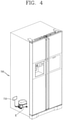
FIG. 4 is a conceptual view of a refrigerator having a linear compressor. - The present invention disclosed herein may be applied to a device and method for controlling a linear compressor. However, the invention disclosed herein is not limited thereto, but may be applied to control devices, control methods, motor control devices, motor control methods, motor noise test devices, and motor noise test methods for all existing compressors to which the present invention is applicable.
- Also, in the description of the technology disclosed in this specification, a detailed description of related arts will be omitted when it is determined that the description may obscure the scope of the technology disclosed in this specification. Also, it should be noted that the accompanying drawings are merely illustrated to easily understand the technical scope disclosed in the specification, and therefore, they should not be construed to limit the scope of the invention as defined by the independent claims.
- In the following description of the present invention, the configuration and corresponding effects of the present invention will be described to solve the above problems.
- An embodiment associated with elements of a linear compressor will be described below with reference to
FIG. 1 . -
FIG. 1 is a block diagram showing a configuration of a control device of a reciprocating compressor according to an embodiment of the present invention. - As shown in
FIG. 1 , the control device of the reciprocating compressor according to an embodiment of the present invention includes a sensing unit a configured to sense a motor voltage and a motor current associated with a motor. - In detail, referring to
FIG. 1 , the sensing unit includes avoltage detection unit 21 configured to detect a motor voltage applied to a motor and acurrent detection unit 22 configured to detect a motor current applied to the motor. Thevoltage detection unit 21 and thecurrent detection unit 22 may deliver information associated with the detected motor voltage and motor current to acontrol unit 25 or astroke estimation unit 23. - Also, as shown in
FIG. 1 , the compressor or the control device thereof according to the present invention may include thestroke estimation unit 23 configured to estimate a stroke on the basis of the detected motor current and motor voltage, and the motor parameters, acomparator 24 configured to compare the stroke estimate and a stroke setpoint, and thecontrol unit 25 configured to change the voltage applied to the motor to control the stroke. - It will be appreciated that the components of the control device shown in
FIG. 1 are not essential and thus a compressor control device having more or fewer components can be implemented. - Meanwhile, the compressor control device according to an embodiment of the present invention is allocable to the reciprocating compressor, but the following description will be based on the linear compressor.
- Also, the
control unit 25 of the linear compressor may be present separately from a refrigerator control unit mounted on a refrigerator to control the operation of the refrigerator. Accordingly, thecontrol unit 25 of the linear compressor may be defined as a compressor control unit. - The components thereof will be described below.
- The
voltage detection unit 21 is configured to detect the motor voltage applied to the compressor motor. In some embodiments, thevoltage detection unit 21 may include a rectification part and a direct current (DC) link part. The rectification part may rectify alternating current (AC) power having a voltage of a predetermined magnitude and output a DC voltage, and the DC link part 12 may include two capacitors. - Also, the
current detection unit 22 is configured to detect the motor current applied to the motor. In some cases, thecurrent detection unit 22 may sense a current flowing a coil of the compressor motor. - Also, the
stroke estimation unit 23 computes the stroke estimate using the detected motor current and motor voltage and the motor parameters and apply the computed stroke estimate to thecomparator 24. - In this case, the
stroke estimation unit 23 computes the strokeestimate using Equation 1 below:
- Thus, the
comparator 24 may compare the stroke estimate and the stroke setpoint and apply a difference signal thereof to thecontrol unit 25. Then, thecontrol unit 25 may control the stroke by changing the voltage applied to the motor. - That is, the
control unit 25 decreases the applied motor voltage when the stroke estimate is larger than the stroke setpoint and increases the applied motor voltage when the stroke estimate is smaller than the stroke setpoint. - The
relay diagnosis unit 26 may determine whether the operation of the relay is normal. A method of determining whether the operation of the relay is normal will be described below with reference toFIG. 3 . - Referring to
FIG. 2 , the relay provided in the compressor and a circuit configuration near the relay are shown. - As shown in
FIG. 2 , the motor of the compressor is supplied with power by an inverter consisting of a plurality of switching elements S1, S2, S3, and S4. In this case, the relay, a first inductor L1, and a second inductor L2 area provided between a first node N1, which is a contact point between the first switch S1 and the second switch S2, and a second node N2, which is a contact point between the third switch S3 and the fourth switch S4. - When the linear compressor shown in
FIG. 2 is installed in the refrigerator, the control device of the refrigerator may generate a switching signal for switching the operation mode of the linear compressor as necessary. - That is, when the refrigerator requires larger cooling power, the control device of the refrigerator may generate the switching signal such that the relay of the linear compressor is connected to point A. In this case, the inductance formed between the compressor and the switch may correspond to the inductance value of the first inductor L1. Hereinafter, a state in which the relay is connected to point A is defined as a first operation mode of the linear compressor.
- In a normal case, the control device of the refrigerator may generate the switching signal such that the relay of the linear compressor is connected to point B. In this case, the inductance formed between the compressor and the switch may correspond to the inductance values of the first inductor L1 and the second inductor L2. Hereinafter, a state in which the relay is connected to point B is defined as a first operation mode of the linear compressor. Thus, the linear compressor further comprises an inductor L1, L2 having a value that varies depending on the state of the relay. In addition, the linear compressor further comprises an inverter S1 to S4 having a plurality of switching elements to supply power to the linear motor. In this regard, the inductor L1, L2 is connected between the switching elements S1 to S4.
- A method of determining whether the relay configured as shown in
FIG. 2 fails will be described in detail below with reference toFIG. 3 . - First, a switching signal for a relay operation mode may be generated (S301). That is, a switching signal for changing the operation mode of the linear compressor may be generated. The switching signal may be generated by a control device of an electronic device having the compressor or by a mechanical switch provided in the linear compressor.
- When the switching signal is generated, the
control unit 25 calculates the magnitude of a first current, which is a current value before the relay is switched (S302). - When the magnitude of the first current is calculated, the
control unit 25 may switch the operation mode of the relay (S303). Meanwhile, thecontrol unit 25 may operate a linear motor under the same condition while calculating the magnitude of the first current and the magnitude of the second current. In addition, thecontrol unit 25 may control a power setpoint applied to the linear motor while the control unit calculates the magnitude of the first current corresponds to a power setpoint applied to the linear motor while the control unit calculates the magnitude of the second current. - The
control unit 25 calculates the magnitude of a second current, which is a current value after the operation mode of the relay is switched (S304). - Also, the
control unit 25 determines whether a ratio between the magnitude of the first current and the magnitude of the second current is in a previously set range (S305). In this regard, the range is set based on a constant associated with the linear motor. - When the ratio between the magnitude of the first current and the magnitude of the second current is in the previously set range, the
control unit 25 determines that a failure has occurred in the relay (S306) and then resets parameters associated with the stroke computation (S307). Meanwhile, thecontrol unit 25 may calculate a variation of the second current with respect to the first current and determine whether the relay fails based on the calculated variation. - On the other hand, when the ratio between the magnitude of the first current and the magnitude of the second current is not in the previously set range, the control unit may determine that the relay is normal (S308).
- Referring to
FIG. 4 , arefrigerator 700 having the linear compressor is shown. Therefrigerator 700 may include a linear compressor 11 and arefrigerator control unit 710, and therefrigerator control unit 710 may generate a mode switching signal for switching the operation mode of the linear compressor. Referring toFIG 1 and4 , the linear compressor 11 may comprise a cylinder configured to form a compression space, a piston configured to move in the cylinder, a linear motor configured to drive the piston, and acurrent detection unit 22 configured to sense a current flowing in the linear motor. Referring toFIG 2 and4 , the linear compressor 11 may further comprise a relay configured to change an operation mode of the linear motor when the mode switching signal is generated by therefrigerator control unit 710. - In detail, the
refrigerator control unit 710 periodically detects a change in load of the refrigerator. When a load variation is greater than or equal to a reference, therefrigerator control unit 710 may generate a mode switching signal such that the relay included in the linear compressor is connected to point A. Also, when there is a need to increase a cooling force of the refrigerator, therefrigerator control unit 710 may generate a mode switching signal such that the relay included in the linear compressor is connected to point A. - On the other hand, the
refrigerator control unit 710 may generate a mode switching signal such that the relay included in the linear compressor is connected to point B under general driving conditions. - The refrigerator control unit may communicate with the compressor control unit (or the control unit 25) and may receive, from the compressor control unit, information regarding whether the relay included in the linear compressor fails. In this regard, with the
compressor control unit 25 is configured to set at least one parameter for computing a stroke of the piston according to the operation mode changed by the relay. In addition, thecompressor control unit 25 may calculate a magnitude of a first current, which is a current flowing in the linear motor before the state of the relay is switched, calculate a magnitude of a second current, which is a current flowing in the linear motor after the state of the relay is switched, and compare the magnitude of the first current and the magnitude of the second current to determine whether the relay fails. Meanwhile, when the mode switching signal is generated by therefrigerator control unit 710, thecompressor control unit 25 may calculate a ratio between the first current and the second current and determines that the relay fails when the calculated ratio is in a previously set range. - Although not shown in
FIG. 4 , the refrigerator may include an output unit such as a display and a communication unit such as a WiFi module. Accordingly, the refrigerator control unit may output the information regarding whether the relay fails, which is received from the compressor control unit, to the display of the refrigerator or may transmit the information to a user terminal by means of the communication unit. - With the linear compressor according to the present invention, a user may check whether the relay fails, and thus it is possible to prevent an unnecessary increase in repair cost.
- Also, with the linear compressor according to the present invention, it is possible to accurately compute the stroke of the linear compressor or the phase difference between the stroke and the motor current even when the relay fails.
Claims (8)
- A linear compressor comprising:a cylinder configured to form a compression space;a piston configured to move in the cylinder;a linear motor configured to drive the piston;a voltage detection unit (21) configured to detect the motor voltage applied to the linear motor;a current detection unit (22) configured to sense a current flowing in the linear motor;a relay configured to change an operation mode of the linear motor;a stroke estimation unit (23) configured to compute a stroke estimate using the detected motor current and motor voltage and the motor parameters, the stroke estimation unit (23) configured to compute the stroke estimate using Equation 1 below:
 a control unit (25) configured to set at least one parameter associated with the computation of the stroke estimate according to the operation mode changed by the relay, wherein the control unit (25) is configured to:calculate a magnitude of a first current, which is a current flowing in the linear motor before the state of the relay is switched,calculate a magnitude of a second current, which is a current flowing in the linear motor after the state of the relay is switched,compare the magnitude of the first current and the magnitude of the second current to determine whether the relay fails,calculate a ratio between the first current and the second current and to determine that the relay fails when the calculated ratio is in a previously set range, andwhen the relay fails, reset parameters associated with the computation of the stroke estimate.
 - The linear compressor of claim 1, wherein the control unit (25) is configured to operate the linear motor under a same condition while calculating the magnitude of the first current and the magnitude of the second current.
- The linear compressor of any one of claims 1 and 2, wherein the control unit is configured to apply a power setpoint to the linear motor while the control unit (25) calculates the magnitude of the first current, wherein the applied power setpoint corresponds to a power setpoint applied to the linear motor while the control unit calculates the magnitude of the second current.
- The linear compressor of any one of claims 1 to 3, wherein the range is set based on a constant associated with the linear motor.
- The linear compressor of any one of claims 1 to 4, wherein the control unit (25) determines that the relay is normal when the calculated ratio is not in the previously set range.
- The linear compressor of any one of claims 1 to 5, further comprising an inductor (L1, L2) having an inductance value that varies depending on the state of the relay.
- The linear compressor of claim 6, further comprising an inverter (S1 to S4) having a plurality of switching elements configured to supply power to the linear motor,
wherein the inductor (L1, L2) is connected between the switching elements. - A refrigerator (700) having a linear compressor according to any one of claims 1 to 7.
Applications Claiming Priority (1)
| Application Number | Priority Date | Filing Date | Title |
|---|---|---|---|
| KR1020190009891A KR102652591B1 (en) | 2019-01-25 | 2019-01-25 | Linear compressor and method for controlling linear compressor |
Publications (2)
| Publication Number | Publication Date |
|---|---|
| EP3686428A1 EP3686428A1 (en) | 2020-07-29 |
| EP3686428B1 true EP3686428B1 (en) | 2022-02-23 |
Family
ID=68280991
Family Applications (1)
| Application Number | Title | Priority Date | Filing Date |
|---|---|---|---|
| EP19203024.5A Not-in-force EP3686428B1 (en) | 2019-01-25 | 2019-10-14 | Linear compressor and method for controlling linear compressor |
Country Status (3)
| Country | Link |
|---|---|
| US (1) | US11384755B2 (en) |
| EP (1) | EP3686428B1 (en) |
| KR (1) | KR102652591B1 (en) |
Families Citing this family (1)
| Publication number | Priority date | Publication date | Assignee | Title |
|---|---|---|---|---|
| US11434883B2 (en) * | 2020-11-19 | 2022-09-06 | Haier Us Appliance Solutions, Inc. | Variable capacity drive circuit for a linear compressor in a refrigeration appliance |
Family Cites Families (12)
| Publication number | Priority date | Publication date | Assignee | Title |
|---|---|---|---|---|
| JPH05164058A (en) * | 1991-12-10 | 1993-06-29 | Fujitsu General Ltd | Air conditioner |
| DE10312234A1 (en) * | 2002-03-20 | 2003-12-18 | Lg Electronics Inc | Operating control device and method for a linear compressor |
| KR100474330B1 (en) * | 2002-05-13 | 2005-03-08 | 엘지전자 주식회사 | Driving comtrol apparatus of reciprocating compressor for refrigerator |
| KR100529937B1 (en) * | 2004-01-08 | 2005-11-22 | 엘지전자 주식회사 | Linear compressor and its method for the same |
| KR20050104434A (en) * | 2004-04-28 | 2005-11-03 | 삼성전자주식회사 | Linear compressor |
| JP4474436B2 (en) * | 2007-05-09 | 2010-06-02 | シャープ株式会社 | Power factor correction circuit, motor drive device and air conditioner |
| US9217429B2 (en) * | 2009-11-18 | 2015-12-22 | Lg Electronics Inc. | Linear compressor |
| US9618004B2 (en) * | 2012-01-25 | 2017-04-11 | Lg Electronics Inc. | Apparatus and method for using a microcomputer and switches to control the flow path for the power of a compressor based upon the compressor's load state |
| CN105890247B (en) * | 2016-04-08 | 2018-08-17 | 广东美的制冷设备有限公司 | The control method and device of air conditioner and its compressor |
| KR20180082895A (en) * | 2017-01-11 | 2018-07-19 | 엘지전자 주식회사 | Linear compressor and method for controlling linear compressor |
| KR102840111B1 (en) * | 2017-01-18 | 2025-07-31 | 엘지전자 주식회사 | Apparatus for controlling linear compressor |
| US10587211B2 (en) * | 2018-04-12 | 2020-03-10 | Haier Us Appliance Solutions, Inc. | Linear compressor and methods of polarity detection |
-
2019
- 2019-01-25 KR KR1020190009891A patent/KR102652591B1/en active Active
- 2019-10-14 EP EP19203024.5A patent/EP3686428B1/en not_active Not-in-force
- 2019-11-01 US US16/671,823 patent/US11384755B2/en active Active
Non-Patent Citations (1)
| Title |
|---|
| None * |
Also Published As
| Publication number | Publication date |
|---|---|
| KR102652591B1 (en) | 2024-04-01 |
| EP3686428A1 (en) | 2020-07-29 |
| US11384755B2 (en) | 2022-07-12 |
| KR20200092686A (en) | 2020-08-04 |
| US20200240406A1 (en) | 2020-07-30 |
Similar Documents
| Publication | Publication Date | Title |
|---|---|---|
| EP3001033B1 (en) | Apparatus and method for controlling a linear compressor | |
| US20050111987A1 (en) | Apparatus and method for controlling operation of reciprocating compressor | |
| EP2620723B1 (en) | Apparatus and method for controlling compressor, and refrigerator having the same | |
| US20060228224A1 (en) | Apparatus for controlling driving of reciprocating compressor and method thereof | |
| EP2071187B1 (en) | Apparatus and method for controlling linear compressor with inverter unit | |
| US20130195613A1 (en) | Apparatus and method for controlling a compressor | |
| US8469674B2 (en) | Operation control device and method of compressor | |
| CN102575657B (en) | Linear compressor | |
| EP2535586A2 (en) | Machine including compressor controlling apparatus and method | |
| EP3686428A1 (en) | Linear compressor and method for controlling linear compressor | |
| US7816873B2 (en) | Linear compressor | |
| JP2008038912A (en) | Compressor internal state estimation device and air conditioner | |
| US20180202430A1 (en) | Apparatus for controlling linear compressor | |
| US11313360B2 (en) | Linear compressor and method for controlling linear compressor | |
| CN111271244A (en) | Linear compressor and control method thereof | |
| KR101800262B1 (en) | Compressor and method for controlling compressor | |
| US11231031B2 (en) | Linear compressor and method for controlling linear compressor | |
| JP4670825B2 (en) | Compressor internal state estimation device and air conditioner | |
| US10982668B2 (en) | Linear compressor and method for controlling linear compressor | |
| KR20200021315A (en) | Linear compressor and method for controlling linear compressor | |
| KR20180082895A (en) | Linear compressor and method for controlling linear compressor | |
| US7352142B2 (en) | Apparatus and method for controlling stroke of reciprocating compressor | |
| US9091272B2 (en) | Apparatus and method for controlling a compressor | |
| KR101748662B1 (en) | Apparatus for controlling linear compressor and method of the same | |
| KR102237724B1 (en) | Linear compressor and method for controlling linear compressor |
Legal Events
| Date | Code | Title | Description |
|---|---|---|---|
| PUAI | Public reference made under article 153(3) epc to a published international application that has entered the european phase |
Free format text: ORIGINAL CODE: 0009012 |
|
| STAA | Information on the status of an ep patent application or granted ep patent |
Free format text: STATUS: REQUEST FOR EXAMINATION WAS MADE |
|
| 17P | Request for examination filed |
Effective date: 20191114 |
|
| AK | Designated contracting states |
Kind code of ref document: A1 Designated state(s): AL AT BE BG CH CY CZ DE DK EE ES FI FR GB GR HR HU IE IS IT LI LT LU LV MC MK MT NL NO PL PT RO RS SE SI SK SM TR |
|
| AX | Request for extension of the european patent |
Extension state: BA ME |
|
| STAA | Information on the status of an ep patent application or granted ep patent |
Free format text: STATUS: EXAMINATION IS IN PROGRESS |
|
| 17Q | First examination report despatched |
Effective date: 20200803 |
|
| GRAP | Despatch of communication of intention to grant a patent |
Free format text: ORIGINAL CODE: EPIDOSNIGR1 |
|
| STAA | Information on the status of an ep patent application or granted ep patent |
Free format text: STATUS: GRANT OF PATENT IS INTENDED |
|
| INTG | Intention to grant announced |
Effective date: 20210928 |
|
| GRAS | Grant fee paid |
Free format text: ORIGINAL CODE: EPIDOSNIGR3 |
|
| GRAA | (expected) grant |
Free format text: ORIGINAL CODE: 0009210 |
|
| STAA | Information on the status of an ep patent application or granted ep patent |
Free format text: STATUS: THE PATENT HAS BEEN GRANTED |
|
| AK | Designated contracting states |
Kind code of ref document: B1 Designated state(s): AL AT BE BG CH CY CZ DE DK EE ES FI FR GB GR HR HU IE IS IT LI LT LU LV MC MK MT NL NO PL PT RO RS SE SI SK SM TR |
|
| REG | Reference to a national code |
Ref country code: GB Ref legal event code: FG4D |
|
| REG | Reference to a national code |
Ref country code: CH Ref legal event code: EP |
|
| REG | Reference to a national code |
Ref country code: DE Ref legal event code: R096 Ref document number: 602019011825 Country of ref document: DE |
|
| REG | Reference to a national code |
Ref country code: AT Ref legal event code: REF Ref document number: 1470658 Country of ref document: AT Kind code of ref document: T Effective date: 20220315 |
|
| REG | Reference to a national code |
Ref country code: IE Ref legal event code: FG4D |
|
| REG | Reference to a national code |
Ref country code: LT Ref legal event code: MG9D |
|
| REG | Reference to a national code |
Ref country code: NL Ref legal event code: MP Effective date: 20220223 |
|
| REG | Reference to a national code |
Ref country code: AT Ref legal event code: MK05 Ref document number: 1470658 Country of ref document: AT Kind code of ref document: T Effective date: 20220223 |
|
| PG25 | Lapsed in a contracting state [announced via postgrant information from national office to epo] |
Ref country code: SE Free format text: LAPSE BECAUSE OF FAILURE TO SUBMIT A TRANSLATION OF THE DESCRIPTION OR TO PAY THE FEE WITHIN THE PRESCRIBED TIME-LIMIT Effective date: 20220223 Ref country code: RS Free format text: LAPSE BECAUSE OF FAILURE TO SUBMIT A TRANSLATION OF THE DESCRIPTION OR TO PAY THE FEE WITHIN THE PRESCRIBED TIME-LIMIT Effective date: 20220223 Ref country code: PT Free format text: LAPSE BECAUSE OF FAILURE TO SUBMIT A TRANSLATION OF THE DESCRIPTION OR TO PAY THE FEE WITHIN THE PRESCRIBED TIME-LIMIT Effective date: 20220623 Ref country code: NO Free format text: LAPSE BECAUSE OF FAILURE TO SUBMIT A TRANSLATION OF THE DESCRIPTION OR TO PAY THE FEE WITHIN THE PRESCRIBED TIME-LIMIT Effective date: 20220523 Ref country code: NL Free format text: LAPSE BECAUSE OF FAILURE TO SUBMIT A TRANSLATION OF THE DESCRIPTION OR TO PAY THE FEE WITHIN THE PRESCRIBED TIME-LIMIT Effective date: 20220223 Ref country code: LT Free format text: LAPSE BECAUSE OF FAILURE TO SUBMIT A TRANSLATION OF THE DESCRIPTION OR TO PAY THE FEE WITHIN THE PRESCRIBED TIME-LIMIT Effective date: 20220223 Ref country code: HR Free format text: LAPSE BECAUSE OF FAILURE TO SUBMIT A TRANSLATION OF THE DESCRIPTION OR TO PAY THE FEE WITHIN THE PRESCRIBED TIME-LIMIT Effective date: 20220223 Ref country code: ES Free format text: LAPSE BECAUSE OF FAILURE TO SUBMIT A TRANSLATION OF THE DESCRIPTION OR TO PAY THE FEE WITHIN THE PRESCRIBED TIME-LIMIT Effective date: 20220223 Ref country code: BG Free format text: LAPSE BECAUSE OF FAILURE TO SUBMIT A TRANSLATION OF THE DESCRIPTION OR TO PAY THE FEE WITHIN THE PRESCRIBED TIME-LIMIT Effective date: 20220523 |
|
| PG25 | Lapsed in a contracting state [announced via postgrant information from national office to epo] |
Ref country code: PL Free format text: LAPSE BECAUSE OF FAILURE TO SUBMIT A TRANSLATION OF THE DESCRIPTION OR TO PAY THE FEE WITHIN THE PRESCRIBED TIME-LIMIT Effective date: 20220223 Ref country code: LV Free format text: LAPSE BECAUSE OF FAILURE TO SUBMIT A TRANSLATION OF THE DESCRIPTION OR TO PAY THE FEE WITHIN THE PRESCRIBED TIME-LIMIT Effective date: 20220223 Ref country code: GR Free format text: LAPSE BECAUSE OF FAILURE TO SUBMIT A TRANSLATION OF THE DESCRIPTION OR TO PAY THE FEE WITHIN THE PRESCRIBED TIME-LIMIT Effective date: 20220524 Ref country code: FI Free format text: LAPSE BECAUSE OF FAILURE TO SUBMIT A TRANSLATION OF THE DESCRIPTION OR TO PAY THE FEE WITHIN THE PRESCRIBED TIME-LIMIT Effective date: 20220223 Ref country code: AT Free format text: LAPSE BECAUSE OF FAILURE TO SUBMIT A TRANSLATION OF THE DESCRIPTION OR TO PAY THE FEE WITHIN THE PRESCRIBED TIME-LIMIT Effective date: 20220223 |
|
| PG25 | Lapsed in a contracting state [announced via postgrant information from national office to epo] |
Ref country code: IS Free format text: LAPSE BECAUSE OF FAILURE TO SUBMIT A TRANSLATION OF THE DESCRIPTION OR TO PAY THE FEE WITHIN THE PRESCRIBED TIME-LIMIT Effective date: 20220623 |
|
| PG25 | Lapsed in a contracting state [announced via postgrant information from national office to epo] |
Ref country code: SM Free format text: LAPSE BECAUSE OF FAILURE TO SUBMIT A TRANSLATION OF THE DESCRIPTION OR TO PAY THE FEE WITHIN THE PRESCRIBED TIME-LIMIT Effective date: 20220223 Ref country code: SK Free format text: LAPSE BECAUSE OF FAILURE TO SUBMIT A TRANSLATION OF THE DESCRIPTION OR TO PAY THE FEE WITHIN THE PRESCRIBED TIME-LIMIT Effective date: 20220223 Ref country code: RO Free format text: LAPSE BECAUSE OF FAILURE TO SUBMIT A TRANSLATION OF THE DESCRIPTION OR TO PAY THE FEE WITHIN THE PRESCRIBED TIME-LIMIT Effective date: 20220223 Ref country code: EE Free format text: LAPSE BECAUSE OF FAILURE TO SUBMIT A TRANSLATION OF THE DESCRIPTION OR TO PAY THE FEE WITHIN THE PRESCRIBED TIME-LIMIT Effective date: 20220223 Ref country code: DK Free format text: LAPSE BECAUSE OF FAILURE TO SUBMIT A TRANSLATION OF THE DESCRIPTION OR TO PAY THE FEE WITHIN THE PRESCRIBED TIME-LIMIT Effective date: 20220223 Ref country code: CZ Free format text: LAPSE BECAUSE OF FAILURE TO SUBMIT A TRANSLATION OF THE DESCRIPTION OR TO PAY THE FEE WITHIN THE PRESCRIBED TIME-LIMIT Effective date: 20220223 |
|
| REG | Reference to a national code |
Ref country code: DE Ref legal event code: R097 Ref document number: 602019011825 Country of ref document: DE |
|
| PG25 | Lapsed in a contracting state [announced via postgrant information from national office to epo] |
Ref country code: AL Free format text: LAPSE BECAUSE OF FAILURE TO SUBMIT A TRANSLATION OF THE DESCRIPTION OR TO PAY THE FEE WITHIN THE PRESCRIBED TIME-LIMIT Effective date: 20220223 |
|
| PLBE | No opposition filed within time limit |
Free format text: ORIGINAL CODE: 0009261 |
|
| STAA | Information on the status of an ep patent application or granted ep patent |
Free format text: STATUS: NO OPPOSITION FILED WITHIN TIME LIMIT |
|
| 26N | No opposition filed |
Effective date: 20221124 |
|
| PG25 | Lapsed in a contracting state [announced via postgrant information from national office to epo] |
Ref country code: SI Free format text: LAPSE BECAUSE OF FAILURE TO SUBMIT A TRANSLATION OF THE DESCRIPTION OR TO PAY THE FEE WITHIN THE PRESCRIBED TIME-LIMIT Effective date: 20220223 |
|
| PG25 | Lapsed in a contracting state [announced via postgrant information from national office to epo] |
Ref country code: MC Free format text: LAPSE BECAUSE OF FAILURE TO SUBMIT A TRANSLATION OF THE DESCRIPTION OR TO PAY THE FEE WITHIN THE PRESCRIBED TIME-LIMIT Effective date: 20220223 |
|
| REG | Reference to a national code |
Ref country code: CH Ref legal event code: PL |
|
| REG | Reference to a national code |
Ref country code: BE Ref legal event code: MM Effective date: 20221031 |
|
| PG25 | Lapsed in a contracting state [announced via postgrant information from national office to epo] |
Ref country code: LU Free format text: LAPSE BECAUSE OF NON-PAYMENT OF DUE FEES Effective date: 20221014 |
|
| PG25 | Lapsed in a contracting state [announced via postgrant information from national office to epo] |
Ref country code: LI Free format text: LAPSE BECAUSE OF NON-PAYMENT OF DUE FEES Effective date: 20221031 Ref country code: IT Free format text: LAPSE BECAUSE OF FAILURE TO SUBMIT A TRANSLATION OF THE DESCRIPTION OR TO PAY THE FEE WITHIN THE PRESCRIBED TIME-LIMIT Effective date: 20220223 Ref country code: FR Free format text: LAPSE BECAUSE OF NON-PAYMENT OF DUE FEES Effective date: 20221031 Ref country code: CH Free format text: LAPSE BECAUSE OF NON-PAYMENT OF DUE FEES Effective date: 20221031 |
|
| PG25 | Lapsed in a contracting state [announced via postgrant information from national office to epo] |
Ref country code: BE Free format text: LAPSE BECAUSE OF NON-PAYMENT OF DUE FEES Effective date: 20221031 |
|
| PG25 | Lapsed in a contracting state [announced via postgrant information from national office to epo] |
Ref country code: IE Free format text: LAPSE BECAUSE OF NON-PAYMENT OF DUE FEES Effective date: 20221014 |
|
| PGFP | Annual fee paid to national office [announced via postgrant information from national office to epo] |
Ref country code: DE Payment date: 20230905 Year of fee payment: 5 |
|
| PG25 | Lapsed in a contracting state [announced via postgrant information from national office to epo] |
Ref country code: HU Free format text: LAPSE BECAUSE OF FAILURE TO SUBMIT A TRANSLATION OF THE DESCRIPTION OR TO PAY THE FEE WITHIN THE PRESCRIBED TIME-LIMIT; INVALID AB INITIO Effective date: 20191014 |
|
| PG25 | Lapsed in a contracting state [announced via postgrant information from national office to epo] |
Ref country code: CY Free format text: LAPSE BECAUSE OF FAILURE TO SUBMIT A TRANSLATION OF THE DESCRIPTION OR TO PAY THE FEE WITHIN THE PRESCRIBED TIME-LIMIT Effective date: 20220223 |
|
| PG25 | Lapsed in a contracting state [announced via postgrant information from national office to epo] |
Ref country code: MK Free format text: LAPSE BECAUSE OF FAILURE TO SUBMIT A TRANSLATION OF THE DESCRIPTION OR TO PAY THE FEE WITHIN THE PRESCRIBED TIME-LIMIT Effective date: 20220223 |
|
| GBPC | Gb: european patent ceased through non-payment of renewal fee |
Effective date: 20231014 |
|
| PG25 | Lapsed in a contracting state [announced via postgrant information from national office to epo] |
Ref country code: TR Free format text: LAPSE BECAUSE OF FAILURE TO SUBMIT A TRANSLATION OF THE DESCRIPTION OR TO PAY THE FEE WITHIN THE PRESCRIBED TIME-LIMIT Effective date: 20220223 |
|
| PG25 | Lapsed in a contracting state [announced via postgrant information from national office to epo] |
Ref country code: GB Free format text: LAPSE BECAUSE OF NON-PAYMENT OF DUE FEES Effective date: 20231014 |
|
| PG25 | Lapsed in a contracting state [announced via postgrant information from national office to epo] |
Ref country code: GB Free format text: LAPSE BECAUSE OF NON-PAYMENT OF DUE FEES Effective date: 20231014 |
|
| PG25 | Lapsed in a contracting state [announced via postgrant information from national office to epo] |
Ref country code: MT Free format text: LAPSE BECAUSE OF FAILURE TO SUBMIT A TRANSLATION OF THE DESCRIPTION OR TO PAY THE FEE WITHIN THE PRESCRIBED TIME-LIMIT Effective date: 20220223 |
|
| REG | Reference to a national code |
Ref country code: DE Ref legal event code: R119 Ref document number: 602019011825 Country of ref document: DE |
|
| PG25 | Lapsed in a contracting state [announced via postgrant information from national office to epo] |
Ref country code: DE Free format text: LAPSE BECAUSE OF NON-PAYMENT OF DUE FEES Effective date: 20250501 |