EP3686412B1 - System of harness and engine case for aircraft engine - Google Patents
System of harness and engine case for aircraft engine Download PDFInfo
- Publication number
- EP3686412B1 EP3686412B1 EP20153123.3A EP20153123A EP3686412B1 EP 3686412 B1 EP3686412 B1 EP 3686412B1 EP 20153123 A EP20153123 A EP 20153123A EP 3686412 B1 EP3686412 B1 EP 3686412B1
- Authority
- EP
- European Patent Office
- Prior art keywords
- aircraft engine
- harness
- metal shield
- wires
- flange
- Prior art date
- Legal status (The legal status is an assumption and is not a legal conclusion. Google has not performed a legal analysis and makes no representation as to the accuracy of the status listed.)
- Active
Links
Images

Classifications
-
- F—MECHANICAL ENGINEERING; LIGHTING; HEATING; WEAPONS; BLASTING
- F02—COMBUSTION ENGINES; HOT-GAS OR COMBUSTION-PRODUCT ENGINE PLANTS
- F02C—GAS-TURBINE PLANTS; AIR INTAKES FOR JET-PROPULSION PLANTS; CONTROLLING FUEL SUPPLY IN AIR-BREATHING JET-PROPULSION PLANTS
- F02C7/00—Features, components parts, details or accessories, not provided for in, or of interest apart form groups F02C1/00 - F02C6/00; Air intakes for jet-propulsion plants
-
- H—ELECTRICITY
- H01—ELECTRIC ELEMENTS
- H01B—CABLES; CONDUCTORS; INSULATORS; SELECTION OF MATERIALS FOR THEIR CONDUCTIVE, INSULATING OR DIELECTRIC PROPERTIES
- H01B7/00—Insulated conductors or cables characterised by their form
- H01B7/17—Protection against damage caused by external factors, e.g. sheaths or armouring
- H01B7/18—Protection against damage caused by wear, mechanical force or pressure; Sheaths; Armouring
-
- B—PERFORMING OPERATIONS; TRANSPORTING
- B64—AIRCRAFT; AVIATION; COSMONAUTICS
- B64D—EQUIPMENT FOR FITTING IN OR TO AIRCRAFT; FLIGHT SUITS; PARACHUTES; ARRANGEMENT OR MOUNTING OF POWER PLANTS OR PROPULSION TRANSMISSIONS IN AIRCRAFT
- B64D29/00—Power-plant nacelles, fairings or cowlings
-
- F—MECHANICAL ENGINEERING; LIGHTING; HEATING; WEAPONS; BLASTING
- F01—MACHINES OR ENGINES IN GENERAL; ENGINE PLANTS IN GENERAL; STEAM ENGINES
- F01D—NON-POSITIVE DISPLACEMENT MACHINES OR ENGINES, e.g. STEAM TURBINES
- F01D25/00—Component parts, details, or accessories, not provided for in, or of interest apart from, other groups
- F01D25/24—Casings; Casing parts, e.g. diaphragms, casing fastenings
- F01D25/243—Flange connections; Bolting arrangements
-
- H—ELECTRICITY
- H01—ELECTRIC ELEMENTS
- H01B—CABLES; CONDUCTORS; INSULATORS; SELECTION OF MATERIALS FOR THEIR CONDUCTIVE, INSULATING OR DIELECTRIC PROPERTIES
- H01B7/00—Insulated conductors or cables characterised by their form
- H01B7/0045—Cable-harnesses
-
- F—MECHANICAL ENGINEERING; LIGHTING; HEATING; WEAPONS; BLASTING
- F02—COMBUSTION ENGINES; HOT-GAS OR COMBUSTION-PRODUCT ENGINE PLANTS
- F02K—JET-PROPULSION PLANTS
- F02K3/00—Plants including a gas turbine driving a compressor or a ducted fan
- F02K3/02—Plants including a gas turbine driving a compressor or a ducted fan in which part of the working fluid by-passes the turbine and combustion chamber
- F02K3/04—Plants including a gas turbine driving a compressor or a ducted fan in which part of the working fluid by-passes the turbine and combustion chamber the plant including ducted fans, i.e. fans with high volume, low pressure outputs, for augmenting the jet thrust, e.g. of double-flow type
- F02K3/06—Plants including a gas turbine driving a compressor or a ducted fan in which part of the working fluid by-passes the turbine and combustion chamber the plant including ducted fans, i.e. fans with high volume, low pressure outputs, for augmenting the jet thrust, e.g. of double-flow type with front fan
-
- F—MECHANICAL ENGINEERING; LIGHTING; HEATING; WEAPONS; BLASTING
- F05—INDEXING SCHEMES RELATING TO ENGINES OR PUMPS IN VARIOUS SUBCLASSES OF CLASSES F01-F04
- F05D—INDEXING SCHEME FOR ASPECTS RELATING TO NON-POSITIVE-DISPLACEMENT MACHINES OR ENGINES, GAS-TURBINES OR JET-PROPULSION PLANTS
- F05D2220/00—Application
- F05D2220/30—Application in turbines
- F05D2220/32—Application in turbines in gas turbines
- F05D2220/323—Application in turbines in gas turbines for aircraft propulsion, e.g. jet engines
-
- F—MECHANICAL ENGINEERING; LIGHTING; HEATING; WEAPONS; BLASTING
- F05—INDEXING SCHEMES RELATING TO ENGINES OR PUMPS IN VARIOUS SUBCLASSES OF CLASSES F01-F04
- F05D—INDEXING SCHEME FOR ASPECTS RELATING TO NON-POSITIVE-DISPLACEMENT MACHINES OR ENGINES, GAS-TURBINES OR JET-PROPULSION PLANTS
- F05D2240/00—Components
- F05D2240/10—Stators
- F05D2240/14—Casings or housings protecting or supporting assemblies within
-
- H—ELECTRICITY
- H01—ELECTRIC ELEMENTS
- H01R—ELECTRICALLY-CONDUCTIVE CONNECTIONS; STRUCTURAL ASSOCIATIONS OF A PLURALITY OF MUTUALLY-INSULATED ELECTRICAL CONNECTING ELEMENTS; COUPLING DEVICES; CURRENT COLLECTORS
- H01R4/00—Electrically-conductive connections between two or more conductive members in direct contact, i.e. touching one another; Means for effecting or maintaining such contact; Electrically-conductive connections having two or more spaced connecting locations for conductors and using contact members penetrating insulation
- H01R4/28—Clamped connections, spring connections
- H01R4/30—Clamped connections, spring connections utilising a screw or nut clamping member
- H01R4/34—Conductive members located under head of screw
Definitions
- the application relates to electrical wire harnesses used in gas turbine engines, and to a grounding thereof.
- Electrical wire harness may be used in gas turbine engines to concurrently route a plurality of wires in a bundle from one location to another.
- Such electrical wire harnesses may have protective sheaths.
- outer braids may be used to protect the bundles of wires of a harness from the surrounding environment, and from chafing that may result from relative movement between the harness and surrounding engine components. The relative movement may be a result of thermal expansion, vibrations, etc.
- current may flow along electrical wire harnesses.
- FR 2 950 205 A1 discloses an aircraft engine according to the preamble of claim 1, and an aircraft engine according to the preamble of claim 11.
- US 7 500 644 B2 discloses a device for maintaining an positioning harnesses on a turbo-jet engine
- GB 2 463 867 A discloses an electrical harness
- an aircraft engine comprising: an engine case having at least one flange; a harness of wires extending alongside, parallel to, and/or in proximity to, the engine case, the harness of wires including a metal shield sleeve externally covering a bundle of wires in a longitudinal direction, at least one break in the metal shield sleeve to provide at least two sleeve segments of the metal shield sleeve longitudinally spaced along the harness of wires; and a conductive contact between the at least one flange and at least one of the sleeve segments.
- an aircraft engine comprising: an engine case, the engine case having at least one flange; a harness of wires extending alongside, parallel to, and/or in proximity to the engine case, the harness of wires including at least two metal shield sleeves externally covering a bundle of wires in a longitudinal direction, the at least two metal shield sleeves being at least partially electrically insulated from one another; and a conductive contact between the at least one flange and at least one of the metal shield sleeve.
- Fig. 1 illustrates a gas turbine engine 10 of a type preferably provided for use in subsonic flight, generally comprising in serial flow communication a fan 12 through which ambient air is propelled, a compressor section 14 for pressurizing the air, a combustor 16 in which the compressed air is mixed with fuel and ignited for generating an annular stream of hot combustion gases, and a turbine section 18 for extracting energy from the combustion gases.
- Components of the engine 10 are rotatable about a longitudinal center axis 11 of the engine 10.
- Engine cases may be shown as 20, including that of a gear box 19.
- the present description uses an aircraft gas turbine for description purposes, the present description is applicable to any aircraft engine, including hybrid/electric engines, for example.
- an exemplary engine case 20 has case portions 21.
- Fig. 2 shows four different case portions 21, though fewer or more case portions 21 may be present.
- the case portions 21 may be known as shells, casings, etc.
- the case portions 21 may conventionally be made of a metallic material or alloys. In an embodiment, the case portions 21 may be made of other materials as well.
- the case portions 21 may be interconnected to one another by flanges 22, or other such connection members.
- the flanges 22 may be a mated flange pair joining annular case sections 21.
- the flanges 22 may be integral parts of the case portions 21. For example, a case portion 21 is cast with an end flange 22.
- Case portions 21 may be sheet metal worked into the shells According to an embodiment shown in Fig. 3 , adjacent case portions 21 are connected to one another by abutment of end flanges 22. Through holes 23 may be defined in the end flanges 22. The through holes 23 may be in register for fasteners 24 to secure the case portions 21 together.
- the fasteners 24 may be bolts and nuts, as shown, but other fasteners include screws and other threaded fasteners, rivets, clamps, etc. This arrangement is one among others to fixedly secure case portions 21 together, with other arrangements including welding, brazing, etc.
- the harness 30 may be an electrical wiring harness that regroups a plurality of various wires serving different functions, tens of various wires.
- the wires are generically shown at 31.
- Exemplary types of wires that may or may not be present in the harness 30 includes individual wires, twist singles (e.g., inner shielded twist singles), twisted pairs (e.g., shielded), and/or twisted triples/triplex (e.g., shielded), among others.
- Wires may be in various configurations, such as solid-core wires, stranded wires, multiconductor cables, type NM cables.
- Such wires may usually include a conductor wire (e.g., a metallic wire) with an insulating sheath, wire armouring, bedding, insulation, separation material and/or sleeve (e.g., a rubber or polymer such as polyvinyl chloride (PVC)).
- a conductor wire e.g., a metallic wire
- an insulating sheath e.g., a insulating sheath, wire armouring, bedding, insulation, separation material and/or sleeve
- sleeve e.g., a rubber or polymer such as polyvinyl chloride (PVC)
- the harness 30 has a flexible metal shield sleeve or sheath surrounding and enclosing the bundle of wires 31.
- the flexible metal shield sleeve 32 may for instance be an outer overbraid 32 (a.k.a, outer braid, shielding braid, metallic braid).
- the braid 32 may be composed of threads woven tightly around the bundle of wires 31.
- the braid 32 includes threads of metal, and is therefore conductive.
- the braid 32 may result from spindle type braiding machine.
- the overbraid 32 provides a protective layer for the bundle of wires 31, for example to protect the bundle of wires 31 from chafing, heat and/or other wear and tear.
- the braid 32 or like metal shield sleeve is generally not rigid or flexible, to allow some flexibility in routing the harness 30 from one engine location to another.
- the harness 30 may further have a protective insulating sheath 33 covering the flexible metal shield sleeve 32.
- the optional protective insulating sheath 33 may be a rubber or polymer such as polyvinyl chloride (PVC), as examples.
- PVC polyvinyl chloride
- the protective insulating sheath 33 is a tape wound onto the sleeve 32.
- One or more breaks 34 are defined in the metal shield sleeve 32, such that the metal shield sleeve is formed of two or more separate segments, shown as 32A, 32B, etc.
- the outer over braid 32 has three breaks 34 along the length of the harness 30.
- the segments may also be regarded as distinct metal shield sleeves 32A, 32B, 32C separated from one another by the breaks 34.
- Such distinct metal shield sleeves 32A, 32B, 32C may hence cover different longitudinal portions of the bundle of wires 31, with no overlap and/or contact between the distinct metal shield sleeves 32A, 32B, 32C.
- the breaks 34 may also be known as discontinuities in the metal shield sleeve 32, as the sleeve 32 is not continuous along the length of the harness 30.
- the discontinuities are conductive discontinuities, as current may not be conducted along the sleeve 32 due to the break 34.
- the breaks 34 in the harness 30 are of at least 0.2 inch (5.08 mm).
- the breaks 34 are between 0.3 to 0.5 inch (7.62 to 12.7 mm). If the protective insulating sheath 33 is present, it may or may not have a break(s) generally aligned with the break(s) 34. In an embodiment, the protective insulating sheath 33 is continuous, but is pierced for the sleeve 32 to be exposed and/or for a conductor wire to pass through the sheath 33.
- the shields 32 are grounded to the engine case 20, by way of a conductive contact, at bonding points.
- the conductive contact 35 may be in the form of a conductor wire 35 (a.k.a., strap, bond strap) whose conducting portion is conductively connected to one of the shield segments (e.g., 32A, 32B, etc) at one end, and to a flange 22 of the engine case 20 at another end.
- the conductor wire 35 may have an insulating sleeve.
- the conductor wire 35 may have appropriate connectors to be connected at its opposed ends.
- the conductor wire 35 may have a terminal lug 36 or bracket to be retained by the fastener 24 as shown in Fig. 3 .
- the conductive contact may be in the form of a direct conductive contact between the material of the sleeve 32 and that of the flanges 22.
- the conductive contact may be in the form of a direct conductive contact between the material of the sleeve 32 with that of metallic stand-off bracket conductively connected to the flange 22.
- the harness 30 extends in close proximity to the engine case 20.
- the harness 30 extends along the engine case 20.
- the harness 30 may extend lengthwise concurrently with the engine case 20.
- the length of the harness 30 may also be transverse to the engine case 20.
- the harness 30 may be coupled to connectors 41 in a firewall 40 of the gas turbine engine.
- the harness 30 may be fabricated, assembled and/or altered for the breaks 34 or for exposed portions of the sleeve 32 to be at locations corresponding to the location of the flanges 22 on the engine case 20 and/or accessory mounting bolt and brackets 24 that are conductive through a bolt.
- the conductive contact between the segments of the sleeve 32, e.g., at the breaks 34, and additional grounding points aid in diverting current away from the harness 30 onto the engine structure and into engine bond straps 42 and mounts ( Fig. 2 ).
- the configuration described with reference to Figs. 2 and 3 with the locations of the bonding points aligned with the flanges 22 of the engine case portions 21 may facilitate the installation of grounding for the harness 30.
- minimal additional hardware may be required to benefit from the advantages of bonding of the harness 30.
- the breaks 34 in the shielding 32 and the ground points promote the current to take the larger skin of the engine diameter, e.g., that of an engine case 20, rather the smaller diameter harness 30.
- Current traveling along the outer shield 32 of the harness 30 may be forced onto the engine structure through conductive contact 35, and may then tend to remain on the engine structure rather than return back onto the harness 30 through another conductive contact 35 due to the reduced impedance of the larger engine component.
- conductive contact 35 is at one of the breaks 34, and is located aft of the engine mount and engine bond straps to promote the current conducting along the skin of the engine and engine to aircraft bond straps 42 rather than being conducting back onto the harness 30 through conductive wires 35.
- the grounding or bonding arrangement for the harness 30 described above may also be used for other structural components of the gas turbine engine 10, i.e., not necessarily an engine case 20.
- the approach is applicable to any aircraft engine type, and not uniquely applicable to gas turbine engines.
- a definition that may be used for the break 34 is an annular gap between two adjacent sleeves 32, sleeve segments of the sleeve 32, the annular gap surrounding the harness (as do the sleeves 32/sleeve segments).
- the annular gap forms an annular discontinuity in the sleeve 32 for example, resulting in a drop of conductivity. This may be referred to as the two metal shield sleeves 32 being at least partially electrically insulated from one another, i.e., there is at least a drop of conductivity.
Landscapes
- Engineering & Computer Science (AREA)
- Mechanical Engineering (AREA)
- General Engineering & Computer Science (AREA)
- Chemical & Material Sciences (AREA)
- Combustion & Propulsion (AREA)
- Aviation & Aerospace Engineering (AREA)
- Shielding Devices Or Components To Electric Or Magnetic Fields (AREA)
- Insulated Conductors (AREA)
- Details Of Indoor Wiring (AREA)
Description
- The application relates to electrical wire harnesses used in gas turbine engines, and to a grounding thereof.
- Electrical wire harness may be used in gas turbine engines to concurrently route a plurality of wires in a bundle from one location to another. Such electrical wire harnesses may have protective sheaths. For example, outer braids may be used to protect the bundles of wires of a harness from the surrounding environment, and from chafing that may result from relative movement between the harness and surrounding engine components. The relative movement may be a result of thermal expansion, vibrations, etc. As a consequence of the conductivity of metallic fibers conventionally used in outer braids or like protective sleeves for wire bundles, current may flow along electrical wire harnesses.
-
FR 2 950 205 A1 claim 11. -
US 7 500 644 B2 discloses a device for maintaining an positioning harnesses on a turbo-jet engine, andGB 2 463 867 A - According to a first aspect of the invention, there is provided an aircraft engine comprising: an engine case having at least one flange; a harness of wires extending alongside, parallel to, and/or in proximity to, the engine case, the harness of wires including a metal shield sleeve externally covering a bundle of wires in a longitudinal direction, at least one break in the metal shield sleeve to provide at least two sleeve segments of the metal shield sleeve longitudinally spaced along the harness of wires; and a conductive contact between the at least one flange and at least one of the sleeve segments.
- According to another aspect of the invention, there is provided an aircraft engine comprising: an engine case, the engine case having at least one flange; a harness of wires extending alongside, parallel to, and/or in proximity to the engine case, the harness of wires including at least two metal shield sleeves externally covering a bundle of wires in a longitudinal direction, the at least two metal shield sleeves being at least partially electrically insulated from one another; and a conductive contact between the at least one flange and at least one of the metal shield sleeve.
- Reference is now made to the accompanying figures in which:
-
Fig. 1 is a schematic longitudinal section view of a gas turbine engine using a system of harness and engine case in accordance with the present disclosure; -
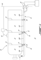
Fig. 2 is a schematic view of a system of harness and engine case in accordance with the present disclosure; and -
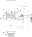
Fig. 3 is a schematic view of a harness of the system ofFig. 2 . -
Fig. 1 illustrates agas turbine engine 10 of a type preferably provided for use in subsonic flight, generally comprising in serial flow communication afan 12 through which ambient air is propelled, acompressor section 14 for pressurizing the air, acombustor 16 in which the compressed air is mixed with fuel and ignited for generating an annular stream of hot combustion gases, and aturbine section 18 for extracting energy from the combustion gases. Components of theengine 10 are rotatable about alongitudinal center axis 11 of theengine 10. Engine cases may be shown as 20, including that of agear box 19. Although the present description uses an aircraft gas turbine for description purposes, the present description is applicable to any aircraft engine, including hybrid/electric engines, for example. - Referring to
Fig. 2 , anexemplary engine case 20 hascase portions 21.Fig. 2 shows fourdifferent case portions 21, though fewer ormore case portions 21 may be present. Thecase portions 21 may be known as shells, casings, etc. Thecase portions 21 may conventionally be made of a metallic material or alloys. In an embodiment, thecase portions 21 may be made of other materials as well. Thecase portions 21 may be interconnected to one another byflanges 22, or other such connection members. Theflanges 22 may be a mated flange pair joiningannular case sections 21. Theflanges 22 may be integral parts of thecase portions 21. For example, acase portion 21 is cast with anend flange 22.Case portions 21 may be sheet metal worked into the shells According to an embodiment shown inFig. 3 ,adjacent case portions 21 are connected to one another by abutment ofend flanges 22. Throughholes 23 may be defined in theend flanges 22. The throughholes 23 may be in register forfasteners 24 to secure thecase portions 21 together. Thefasteners 24 may be bolts and nuts, as shown, but other fasteners include screws and other threaded fasteners, rivets, clamps, etc. This arrangement is one among others to fixedlysecure case portions 21 together, with other arrangements including welding, brazing, etc. - Referring to
Figs. 2 and3 , a harness is generally shown at 30. Theharness 30 may be an electrical wiring harness that regroups a plurality of various wires serving different functions, tens of various wires. InFig. 3 , the wires are generically shown at 31. Exemplary types of wires that may or may not be present in theharness 30 includes individual wires, twist singles (e.g., inner shielded twist singles), twisted pairs (e.g., shielded), and/or twisted triples/triplex (e.g., shielded), among others. Wires may be in various configurations, such as solid-core wires, stranded wires, multiconductor cables, type NM cables. Such wires may usually include a conductor wire (e.g., a metallic wire) with an insulating sheath, wire armouring, bedding, insulation, separation material and/or sleeve (e.g., a rubber or polymer such as polyvinyl chloride (PVC)). - The
harness 30 has a flexible metal shield sleeve or sheath surrounding and enclosing the bundle ofwires 31. The flexiblemetal shield sleeve 32 may for instance be an outer overbraid 32 (a.k.a, outer braid, shielding braid, metallic braid). Thebraid 32 may be composed of threads woven tightly around the bundle ofwires 31. Thebraid 32 includes threads of metal, and is therefore conductive. For example, thebraid 32 may result from spindle type braiding machine. The overbraid 32 provides a protective layer for the bundle ofwires 31, for example to protect the bundle ofwires 31 from chafing, heat and/or other wear and tear. Thebraid 32 or like metal shield sleeve is generally not rigid or flexible, to allow some flexibility in routing theharness 30 from one engine location to another. Theharness 30 may further have a protective insulating sheath 33 covering the flexiblemetal shield sleeve 32. The optional protective insulating sheath 33 may be a rubber or polymer such as polyvinyl chloride (PVC), as examples. As an embodiment, the protective insulating sheath 33 is a tape wound onto thesleeve 32. - One or
more breaks 34 are defined in themetal shield sleeve 32, such that the metal shield sleeve is formed of two or more separate segments, shown as 32A, 32B, etc. In the embodiment ofFig. 2 , the outer overbraid 32 has threebreaks 34 along the length of theharness 30. Although the above description refers to the harness having a singlemetal shield sleeve 32, the segments may also be regarded as distinctmetal shield sleeves breaks 34. Such distinctmetal shield sleeves wires 31, with no overlap and/or contact between the distinctmetal shield sleeves wires 31, from end to end of theharness 30, may have a length L = L1+L2+L3, with 32A covering L1, 32B covering L2, and 32C covering L3, and with afirst break 34 between 32A and 32B, and asecond break 34 between 32B and 32C. Thebreaks 34 may also be known as discontinuities in themetal shield sleeve 32, as thesleeve 32 is not continuous along the length of theharness 30. The discontinuities are conductive discontinuities, as current may not be conducted along thesleeve 32 due to thebreak 34. According to an embodiment, thebreaks 34 in theharness 30 are of at least 0.2 inch (5.08 mm). In an embodiment, thebreaks 34 are between 0.3 to 0.5 inch (7.62 to 12.7 mm). If the protective insulating sheath 33 is present, it may or may not have a break(s) generally aligned with the break(s) 34. In an embodiment, the protective insulating sheath 33 is continuous, but is pierced for thesleeve 32 to be exposed and/or for a conductor wire to pass through the sheath 33. - On either side of the
breaks 34, theshields 32 are grounded to theengine case 20, by way of a conductive contact, at bonding points. For example, theconductive contact 35 may be in the form of a conductor wire 35 (a.k.a., strap, bond strap) whose conducting portion is conductively connected to one of the shield segments (e.g., 32A, 32B, etc) at one end, and to aflange 22 of theengine case 20 at another end. Theconductor wire 35 may have an insulating sleeve. Theconductor wire 35 may have appropriate connectors to be connected at its opposed ends. For example, theconductor wire 35 may have aterminal lug 36 or bracket to be retained by thefastener 24 as shown inFig. 3 . As another embodiment, the conductive contact may be in the form of a direct conductive contact between the material of thesleeve 32 and that of theflanges 22. As another embodiment, the conductive contact may be in the form of a direct conductive contact between the material of thesleeve 32 with that of metallic stand-off bracket conductively connected to theflange 22. - As shown in
Fig. 2 , theharness 30 extends in close proximity to theengine case 20. For example, theharness 30 extends along theengine case 20. For example, theharness 30 may extend lengthwise concurrently with theengine case 20. The length of theharness 30 may also be transverse to theengine case 20. Theharness 30 may be coupled toconnectors 41 in a firewall 40 of the gas turbine engine. Theharness 30 may be fabricated, assembled and/or altered for thebreaks 34 or for exposed portions of thesleeve 32 to be at locations corresponding to the location of theflanges 22 on theengine case 20 and/or accessory mounting bolt andbrackets 24 that are conductive through a bolt. The conductive contact between the segments of thesleeve 32, e.g., at thebreaks 34, and additional grounding points aid in diverting current away from theharness 30 onto the engine structure and into engine bond straps 42 and mounts (Fig. 2 ). - The configuration described with reference to
Figs. 2 and3 , with the locations of the bonding points aligned with theflanges 22 of theengine case portions 21 may facilitate the installation of grounding for theharness 30. For example, minimal additional hardware may be required to benefit from the advantages of bonding of theharness 30. Thebreaks 34 in the shielding 32 and the ground points promote the current to take the larger skin of the engine diameter, e.g., that of anengine case 20, rather thesmaller diameter harness 30. Current traveling along theouter shield 32 of theharness 30 may be forced onto the engine structure throughconductive contact 35, and may then tend to remain on the engine structure rather than return back onto theharness 30 through anotherconductive contact 35 due to the reduced impedance of the larger engine component. According to an embodiment,conductive contact 35 is at one of thebreaks 34, and is located aft of the engine mount and engine bond straps to promote the current conducting along the skin of the engine and engine toaircraft bond straps 42 rather than being conducting back onto theharness 30 throughconductive wires 35. - The above description is meant to be exemplary only, and one skilled in the art will recognize that changes may be made to the embodiments described without departing from the scope of the invention disclosed. For example, the grounding or bonding arrangement for the
harness 30 described above may also be used for other structural components of thegas turbine engine 10, i.e., not necessarily anengine case 20. The approach is applicable to any aircraft engine type, and not uniquely applicable to gas turbine engines. A definition that may be used for thebreak 34 is an annular gap between twoadjacent sleeves 32, sleeve segments of thesleeve 32, the annular gap surrounding the harness (as do thesleeves 32/sleeve segments). The annular gap forms an annular discontinuity in thesleeve 32 for example, resulting in a drop of conductivity. This may be referred to as the twometal shield sleeves 32 being at least partially electrically insulated from one another, i.e., there is at least a drop of conductivity.
Claims (15)
- An aircraft engine (10) comprising:an engine case (20) having at least one flange (22); anda harness of wires (30) extending in proximity to the engine case (20), characterised in that:the harness of wires (30) includes a metal shield sleeve (32) externally covering a bundle of wires (31) in a longitudinal direction, wherein there is at least one break (34) in the metal shield sleeve (32) to provide at least two sleeve segments (32A, 32B, 32C, 32D) of the metal shield sleeve (32) longitudinally spaced along the harness of wires (30); andthe aircraft engine (10) further comprises a conductive contact (35) between the at least one flange (22) and at least one of the sleeve segments (32A...32D).
- The aircraft engine according to claim 1, wherein the metal shield sleeve (32) is an outer braid (32) with metallic content.
- The aircraft engine according to claim 1 or 2, wherein the at least one break (34) has a size of at least 0.2 inches (5.08 mm) between ends of adjacent ones of the separate sleeve segments (32A... 32D).
- The aircraft engine according to any of claims 1 to 3, wherein the at least one break (34) has a maximum size of 0.5 inches (12.7 mm) between ends of adjacent ones of the separate sleeve segments (32A...32D).
- The aircraft engine according to any preceding claim, wherein the conductive contact (35) comprises a conductive wire (35), and the engine further comprises a connector (36) at a junction between the conductive wire (35) and the at least one flange (22).
- The aircraft engine according to claim 5, wherein the connector (36) is a terminal lug (36).
- The aircraft engine according to claim 5 or 6, wherein the conductive wire (35) has an end connected to or adjacent to an end of one of the separate segments (32A...32D) of the metal shield sleeve (32).
- The aircraft engine according to any preceding claim, further comprising an insulating sheath (33) covering the metal shield sleeve (32) and the at least one break (34), an opening being defined in the insulating sheath (33) for said conductive contact (35).
- The aircraft engine according to any preceding claim, wherein the at least one flange (22) includes a mated flange pair joining annular case sections (21).
- The aircraft engine according to any preceding claim, wherein the engine case (20) has a plurality of engine case portions (21) interconnected by the flanges (22), the harness of wires (30) extending along the engine case (20) for one said break (34) to be in proximity to each one of said flanges (22).
- An aircraft engine (10) comprising:an engine case (20) having at least one flange (22); anda harness of wires (30) extending in proximity to the engine case (20), characterised in that:the harness of wires (30) includes at least two metal shield sleeves (32) externally covering a bundle of wires (31) in a longitudinal direction, the at least two metal shield sleeves (32) being at least partially electrically insulated from one another; andthe aircraft engine (10) further comprises a conductive contact (35) between the at least one flange (22) and at least one of the metal shield sleeves (32).
- The aircraft engine according to claim 11, wherein the metal shield sleeves (32) are outer braids with metallic content.
- The aircraft engine according to any of claims 11 and 12, wherein the electrical insulation is provided by a separation (34) between adjacent ends of the metal shield sleeves (32), the separation (34) having a size of at least 0.2 inches (5.08 mm) between ends of adjacent ones of the separate sleeve segments (32A...32D) wherein, optionally the separation (34) has a maximum size of 0.5 inches (12.7 mm) between said adjacent ends.
- The aircraft engine according to any of claims 11 to 13, wherein the at least one flange (22) includes a mated flange pair connecting annular engine case portions (21).
- The aircraft engine according to any of claims 11 to 14, wherein the conductive contact (35) comprises a conductive wire (35), and the engine further comprises a connector (36) at a junction between the conductive wire (35) and the at least one flange (22) wherein optionally the connector (136) is a terminal lug (36).
Applications Claiming Priority (1)
| Application Number | Priority Date | Filing Date | Title |
|---|---|---|---|
| US16/255,444 US11211184B2 (en) | 2019-01-23 | 2019-01-23 | System of harness and engine case for aircraft engine |
Publications (2)
| Publication Number | Publication Date |
|---|---|
| EP3686412A1 EP3686412A1 (en) | 2020-07-29 |
| EP3686412B1 true EP3686412B1 (en) | 2023-05-10 |
Family
ID=69570506
Family Applications (1)
| Application Number | Title | Priority Date | Filing Date |
|---|---|---|---|
| EP20153123.3A Active EP3686412B1 (en) | 2019-01-23 | 2020-01-22 | System of harness and engine case for aircraft engine |
Country Status (4)
| Country | Link |
|---|---|
| US (1) | US11211184B2 (en) |
| EP (1) | EP3686412B1 (en) |
| CA (1) | CA3069191C (en) |
| PL (1) | PL3686412T3 (en) |
Family Cites Families (64)
| Publication number | Priority date | Publication date | Assignee | Title |
|---|---|---|---|---|
| US5152395A (en) | 1990-09-28 | 1992-10-06 | The Boeing Company | Wire carrier and method of using same |
| US5196673A (en) | 1990-11-13 | 1993-03-23 | Tanis Peter G | Aircraft intake pipe bolt heater for electrically preheating an aircraft engine |
| US5458343A (en) | 1994-08-11 | 1995-10-17 | General Electric Company | Aircraft engine firewall seal |
| US5831217A (en) | 1995-11-16 | 1998-11-03 | The Boeing Company | Wire bundle sealing system having individual tubular segments gathered around the wire bundles and containing sealant |
| US5947248A (en) | 1997-08-29 | 1999-09-07 | American Cooling Systems, Llc | Electric fan clutch |
| US6232577B1 (en) | 1998-07-10 | 2001-05-15 | Robert P. Reiff | Apparatus and method for heating cold engines |
| FR2807227B1 (en) | 2000-04-04 | 2002-06-28 | Ecia Equip Composants Ind Auto | ELECTRIC BEAM SLEEVE, CORRESPONDING ASSEMBLY, CORRESPONDING MODULE AND DOOR |
| US6891302B1 (en) | 2000-09-23 | 2005-05-10 | Christopher W. Gabrys | Light-weight high-power electrical machine |
| US8195295B2 (en) | 2008-03-20 | 2012-06-05 | Greatbatch Ltd. | Shielded three-terminal flat-through EMI/energy dissipating filter |
| WO2003014591A2 (en) | 2001-08-09 | 2003-02-20 | Federal-Mogul Powertrain, Inc. | Vibration damping corrugated flexible sleeving |
| US6863930B2 (en) | 2002-09-06 | 2005-03-08 | Delphi Technologies, Inc. | Refractory metal mask and methods for coating an article and forming a sensor |
| US6848652B2 (en) | 2003-02-28 | 2005-02-01 | Sikorsky Aircraft Corporation | Aircraft heater |
| US6745568B1 (en) | 2003-03-27 | 2004-06-08 | Richard K. Squires | Turbo system and method of installing |
| FR2856772B1 (en) | 2003-06-27 | 2006-07-28 | Snecma Moteurs | DEVICE FOR ESTABLISHING AND MAINTAINING ELECTRIC HARNESSES ON A TURBOREACTOR |
| US7219424B2 (en) | 2004-03-11 | 2007-05-22 | Honeywell International, Inc. | Method for temporary repair of the overbraid for metal overbraided wiring harnesses |
| JP2006288107A (en) | 2005-04-01 | 2006-10-19 | Honda Motor Co Ltd | Engine harness outlet structure |
| DE102005015585B3 (en) | 2005-04-05 | 2006-10-05 | Kaniut, Herbert, Dipl.-Ing. | Combination-supersonic-adjustment-nozzle for e.g. injector-centrifugal-turbines-engine, has nozzle stream bundling unit with small supersonic auxiliary nozzles to load initial-intake-injector to increase the intake effect of engines |
| US7516621B2 (en) | 2005-08-04 | 2009-04-14 | Hamilton Sundstrand Corporation | Modular LRU accessory mounting substrate for auxiliary power unit |
| JP2007213884A (en) | 2006-02-08 | 2007-08-23 | Calsonic Kansei Corp | Unit case, conductor therefor, and manufacturing method therefor |
| US20110000206A1 (en) | 2007-01-24 | 2011-01-06 | Torok Aprad | Progressive thermodynamic system |
| US7506619B1 (en) | 2007-10-12 | 2009-03-24 | Freudenberg-Nok General Partnership | Tunable hybrid bracket assembly |
| US8083557B2 (en) | 2008-01-18 | 2011-12-27 | Steven Sullivan | Method and apparatus for powering of amphibious craft |
| US7534965B1 (en) | 2008-01-29 | 2009-05-19 | Thompson David M | Cable grommet with ball and socket |
| US8140242B2 (en) | 2008-05-22 | 2012-03-20 | United Technologies Corp. | Systems and methods involving multiplexed engine control signals |
| GB2460693A (en) | 2008-06-06 | 2009-12-09 | Rolls Royce Plc | Conduit assembly |
| GB2463867A (en) | 2008-09-24 | 2010-03-31 | Rolls Royce Plc | An electrical harness |
| WO2010062788A2 (en) | 2008-11-03 | 2010-06-03 | Mary Geddry | Direct current brushless machine and wind tubrine system |
| US9885313B2 (en) | 2009-03-17 | 2018-02-06 | United Technologes Corporation | Gas turbine engine bifurcation located fan variable area nozzle |
| WO2011024928A1 (en) | 2009-08-24 | 2011-03-03 | Kawanishi Eiji | Hybrid power generator coupled to gravity power generator using balance which has pressure load device |
| US8816711B2 (en) | 2009-08-26 | 2014-08-26 | United Technologies Corporation | Electrical probe assembly |
| FR2950205B1 (en) | 2009-09-11 | 2011-11-11 | Snecma | DEVICE FOR CONNECTING AN INTEGRATED SENSOR TO AN ELECTRIC HARNESS FOR AN AIRCRAFT ENGINE |
| FR2962404B1 (en) | 2010-07-08 | 2012-07-20 | Eurocopter France | ELECTRICAL ARCHITECTURE FOR AN AIRCRAFT WITH A HYBRID MOTORIZED TURNING SAIL |
| CN102418811B (en) | 2010-09-28 | 2014-12-10 | 中国商用飞机有限责任公司 | Sealed wall penetrating piece |
| US20120151934A1 (en) | 2010-12-17 | 2012-06-21 | General Vortex Energy, Inc. | Recuperator with wire mesh |
| US20120173076A1 (en) | 2011-01-04 | 2012-07-05 | Larry Gene Anderson | System and method for diagnosing a turbocharger |
| GB2494133B (en) | 2011-08-30 | 2015-10-07 | Ge Aviat Systems Ltd | Power distribution in aircraft |
| FR2982088B1 (en) | 2011-10-26 | 2013-12-27 | Airbus Operations Sas | ELECTRICAL HARNESS EQUIPPED WITH A DEVICE FOR DISENGAGING ITS ELECTRICALLY CONDUCTIVE ELEMENTS WITH THE RIGHT TO PASS A WALL |
| WO2013126142A2 (en) | 2011-12-29 | 2013-08-29 | Rolls-Royce Corporation | Platform with engine and wiring harness system, platform with controlled system and wiring harness system, and wiring harness system |
| GB2504997A (en) | 2012-08-17 | 2014-02-19 | Caterham Technology And Innovation Ltd | Sports car and range of sports cars |
| US9627874B2 (en) | 2012-09-12 | 2017-04-18 | Unison Industries, Llc | Mounting device and method of assembling the same |
| JP5255147B1 (en) | 2012-10-12 | 2013-08-07 | 英治 川西 | Ship vertical propulsion device |
| CN103775139B (en) | 2012-10-26 | 2015-09-23 | 中航商用航空发动机有限责任公司 | The clearance control system of turbogenerator and the clearance control method of turbogenerator |
| US20140116752A1 (en) | 2012-10-30 | 2014-05-01 | United Technologies Corporation | Lower firewall plate grommet |
| US9725163B2 (en) | 2012-12-24 | 2017-08-08 | Borealis Technical Limited | Electric power connector for aircraft drive wheel drive system |
| JP5987686B2 (en) * | 2012-12-28 | 2016-09-07 | 日立金属株式会社 | Wire harness |
| US9160452B2 (en) | 2012-12-29 | 2015-10-13 | Zephyr Photonics Inc. | Apparatus for modular implementation of multi-function active optical cables |
| GB201305723D0 (en) | 2013-03-28 | 2013-05-15 | Rolls Royce Plc | Mounting arrangement |
| WO2014178731A2 (en) | 2013-04-29 | 2014-11-06 | Robert Gulliver Lynn | A rotor assembly for an open cycle engine, and an open cycle engine |
| JP5935787B2 (en) * | 2013-11-27 | 2016-06-15 | 住友電装株式会社 | Wire harness and wire harness manufacturing method |
| US9205920B2 (en) | 2013-12-30 | 2015-12-08 | Google Inc. | Wiring harness for an aerial vehicle |
| CN103769705B (en) | 2014-01-17 | 2016-06-15 | 清华大学 | A kind of Multifunctional main axis mechanism for dark aperture spark machined |
| JP6134681B2 (en) | 2014-03-24 | 2017-05-24 | ヤンマー株式会社 | engine |
| US9836573B2 (en) | 2014-10-16 | 2017-12-05 | TATA TECHNOLOGIES PTE_Limited | Method and system for multilateral validation of wire harness design outputs |
| US10590855B2 (en) | 2015-02-03 | 2020-03-17 | United Technologies Corporation | Distributed electrical architecture for a gas turbine engine |
| US9963282B2 (en) | 2015-03-28 | 2018-05-08 | Eurotech Distributors, Inc. | Adhesive system apparatus and method |
| JP6304175B2 (en) | 2015-08-19 | 2018-04-04 | 株式会社デンソー | Electric motor |
| CN105513850B (en) | 2015-12-03 | 2017-10-10 | 中国南方航空工业(集团)有限公司 | Aviation piston engine circuit breaker, magneto and aviation piston engine |
| CN105618532B (en) | 2015-12-23 | 2017-11-24 | 中国航空工业集团公司北京航空制造工程研究所 | Gap support unit, gap supporting tool and bending forming method |
| CN205382961U (en) | 2016-01-08 | 2016-07-13 | 沈阳航空航天大学 | Novel brush type sealing structure with elastic support piece |
| CN106505744B (en) | 2016-11-08 | 2018-02-27 | 中国商用飞机有限责任公司北京民用飞机技术研究中心 | Eliminate the aircraft electrical power supply system and its electric energy distribution method of main electric energy transmission wire harness |
| CN106709166B (en) | 2016-12-07 | 2020-05-05 | 中国商用飞机有限责任公司 | Laying method of aircraft wire harness |
| JP6724763B2 (en) * | 2016-12-19 | 2020-07-15 | 住友電装株式会社 | Wire harness |
| JP6708145B2 (en) * | 2017-02-22 | 2020-06-10 | 住友電装株式会社 | Wire harness |
| JP7017440B2 (en) * | 2018-03-07 | 2022-02-08 | 矢崎総業株式会社 | Manufacturing method of electric wire and electric wire |
-
2019
- 2019-01-23 US US16/255,444 patent/US11211184B2/en active Active
-
2020
- 2020-01-21 CA CA3069191A patent/CA3069191C/en active Active
- 2020-01-22 PL PL20153123.3T patent/PL3686412T3/en unknown
- 2020-01-22 EP EP20153123.3A patent/EP3686412B1/en active Active
Also Published As
| Publication number | Publication date |
|---|---|
| CA3069191C (en) | 2025-09-23 |
| US20200234849A1 (en) | 2020-07-23 |
| CA3069191A1 (en) | 2020-07-23 |
| PL3686412T3 (en) | 2023-09-04 |
| EP3686412A1 (en) | 2020-07-29 |
| US11211184B2 (en) | 2021-12-28 |
Similar Documents
| Publication | Publication Date | Title |
|---|---|---|
| US9204497B2 (en) | Electrical structure having a grounding plane | |
| ES2335241T3 (en) | ELECTRIC HARNES SCREENED, IN PARTICULAR FOR AN AIRCRAFT ENGINE. | |
| US9520705B2 (en) | Lightning protection for spaced electrical bundles | |
| US5380224A (en) | Repairable cable assembly | |
| EP2991462B1 (en) | Earthing arrangement for electrical panel | |
| JP2011097692A (en) | Wire harness | |
| EP1410447B1 (en) | Extendible drain members for grounding rfi/emi shielding | |
| CN112292791B (en) | Electrical harness for a turbomachine | |
| US9627788B2 (en) | Electrical harness connector | |
| CN103917413A (en) | Wire harness with protective member | |
| US9520679B2 (en) | Earthing arrangement for electrical panel | |
| CN108075250A (en) | The protection structure and harness of wire joint portion | |
| US9036323B1 (en) | Power feeder shielding for electromagnetic protection | |
| US9559507B2 (en) | Mounting bracket assembly for an electrical cable | |
| CA3069191C (en) | System of harness and engine case for aircraft engine | |
| US6143986A (en) | Method and arrangement for easily repairing electrical harness for aircraft jet engine | |
| US9892826B2 (en) | Electric wire structure and method for electromagnetic shielding of electric wire | |
| CN110431642B (en) | Conductive wire | |
| US8692114B1 (en) | Wiring harness conduits shield interconnect | |
| CN105356166A (en) | Aeroengine cable | |
| US9112343B1 (en) | Power feeder shielding for electromagnetic protection | |
| CN209896404U (en) | Vibration-resistant environment adapter cable | |
| EP3503326B1 (en) | Hybrid electrical harness and method of making | |
| KR20180062685A (en) | Joint terminal for wire applyed shielding resin and shield wire applied shielding resin having it | |
| US8791373B1 (en) | Method and apparatus for providing an electromagnetic pulse shield ground path |
Legal Events
| Date | Code | Title | Description |
|---|---|---|---|
| PUAI | Public reference made under article 153(3) epc to a published international application that has entered the european phase |
Free format text: ORIGINAL CODE: 0009012 |
|
| STAA | Information on the status of an ep patent application or granted ep patent |
Free format text: STATUS: THE APPLICATION HAS BEEN PUBLISHED |
|
| AK | Designated contracting states |
Kind code of ref document: A1 Designated state(s): AL AT BE BG CH CY CZ DE DK EE ES FI FR GB GR HR HU IE IS IT LI LT LU LV MC MK MT NL NO PL PT RO RS SE SI SK SM TR |
|
| AX | Request for extension of the european patent |
Extension state: BA ME |
|
| STAA | Information on the status of an ep patent application or granted ep patent |
Free format text: STATUS: REQUEST FOR EXAMINATION WAS MADE |
|
| 17P | Request for examination filed |
Effective date: 20210129 |
|
| RBV | Designated contracting states (corrected) |
Designated state(s): AL AT BE BG CH CY CZ DE DK EE ES FI FR GB GR HR HU IE IS IT LI LT LU LV MC MK MT NL NO PL PT RO RS SE SI SK SM TR |
|
| GRAP | Despatch of communication of intention to grant a patent |
Free format text: ORIGINAL CODE: EPIDOSNIGR1 |
|
| RIC1 | Information provided on ipc code assigned before grant |
Ipc: F02C 7/00 20060101AFI20221013BHEP |
|
| STAA | Information on the status of an ep patent application or granted ep patent |
Free format text: STATUS: GRANT OF PATENT IS INTENDED |
|
| INTG | Intention to grant announced |
Effective date: 20221117 |
|
| GRAS | Grant fee paid |
Free format text: ORIGINAL CODE: EPIDOSNIGR3 |
|
| GRAA | (expected) grant |
Free format text: ORIGINAL CODE: 0009210 |
|
| STAA | Information on the status of an ep patent application or granted ep patent |
Free format text: STATUS: THE PATENT HAS BEEN GRANTED |
|
| AK | Designated contracting states |
Kind code of ref document: B1 Designated state(s): AL AT BE BG CH CY CZ DE DK EE ES FI FR GB GR HR HU IE IS IT LI LT LU LV MC MK MT NL NO PL PT RO RS SE SI SK SM TR |
|
| REG | Reference to a national code |
Ref country code: GB Ref legal event code: FG4D |
|
| REG | Reference to a national code |
Ref country code: AT Ref legal event code: REF Ref document number: 1566882 Country of ref document: AT Kind code of ref document: T Effective date: 20230515 Ref country code: CH Ref legal event code: EP |
|
| REG | Reference to a national code |
Ref country code: DE Ref legal event code: R096 Ref document number: 602020010554 Country of ref document: DE |
|
| REG | Reference to a national code |
Ref country code: IE Ref legal event code: FG4D |
|
| P01 | Opt-out of the competence of the unified patent court (upc) registered |
Effective date: 20230530 |
|
| REG | Reference to a national code |
Ref country code: LT Ref legal event code: MG9D |
|
| REG | Reference to a national code |
Ref country code: NL Ref legal event code: MP Effective date: 20230510 |
|
| REG | Reference to a national code |
Ref country code: AT Ref legal event code: MK05 Ref document number: 1566882 Country of ref document: AT Kind code of ref document: T Effective date: 20230510 |
|
| PG25 | Lapsed in a contracting state [announced via postgrant information from national office to epo] |
Ref country code: SE Free format text: LAPSE BECAUSE OF FAILURE TO SUBMIT A TRANSLATION OF THE DESCRIPTION OR TO PAY THE FEE WITHIN THE PRESCRIBED TIME-LIMIT Effective date: 20230510 Ref country code: PT Free format text: LAPSE BECAUSE OF FAILURE TO SUBMIT A TRANSLATION OF THE DESCRIPTION OR TO PAY THE FEE WITHIN THE PRESCRIBED TIME-LIMIT Effective date: 20230911 Ref country code: NO Free format text: LAPSE BECAUSE OF FAILURE TO SUBMIT A TRANSLATION OF THE DESCRIPTION OR TO PAY THE FEE WITHIN THE PRESCRIBED TIME-LIMIT Effective date: 20230810 Ref country code: NL Free format text: LAPSE BECAUSE OF FAILURE TO SUBMIT A TRANSLATION OF THE DESCRIPTION OR TO PAY THE FEE WITHIN THE PRESCRIBED TIME-LIMIT Effective date: 20230510 Ref country code: ES Free format text: LAPSE BECAUSE OF FAILURE TO SUBMIT A TRANSLATION OF THE DESCRIPTION OR TO PAY THE FEE WITHIN THE PRESCRIBED TIME-LIMIT Effective date: 20230510 Ref country code: AT Free format text: LAPSE BECAUSE OF FAILURE TO SUBMIT A TRANSLATION OF THE DESCRIPTION OR TO PAY THE FEE WITHIN THE PRESCRIBED TIME-LIMIT Effective date: 20230510 |
|
| PG25 | Lapsed in a contracting state [announced via postgrant information from national office to epo] |
Ref country code: RS Free format text: LAPSE BECAUSE OF FAILURE TO SUBMIT A TRANSLATION OF THE DESCRIPTION OR TO PAY THE FEE WITHIN THE PRESCRIBED TIME-LIMIT Effective date: 20230510 Ref country code: LV Free format text: LAPSE BECAUSE OF FAILURE TO SUBMIT A TRANSLATION OF THE DESCRIPTION OR TO PAY THE FEE WITHIN THE PRESCRIBED TIME-LIMIT Effective date: 20230510 Ref country code: LT Free format text: LAPSE BECAUSE OF FAILURE TO SUBMIT A TRANSLATION OF THE DESCRIPTION OR TO PAY THE FEE WITHIN THE PRESCRIBED TIME-LIMIT Effective date: 20230510 Ref country code: IS Free format text: LAPSE BECAUSE OF FAILURE TO SUBMIT A TRANSLATION OF THE DESCRIPTION OR TO PAY THE FEE WITHIN THE PRESCRIBED TIME-LIMIT Effective date: 20230910 Ref country code: HR Free format text: LAPSE BECAUSE OF FAILURE TO SUBMIT A TRANSLATION OF THE DESCRIPTION OR TO PAY THE FEE WITHIN THE PRESCRIBED TIME-LIMIT Effective date: 20230510 Ref country code: GR Free format text: LAPSE BECAUSE OF FAILURE TO SUBMIT A TRANSLATION OF THE DESCRIPTION OR TO PAY THE FEE WITHIN THE PRESCRIBED TIME-LIMIT Effective date: 20230811 |
|
| PG25 | Lapsed in a contracting state [announced via postgrant information from national office to epo] |
Ref country code: FI Free format text: LAPSE BECAUSE OF FAILURE TO SUBMIT A TRANSLATION OF THE DESCRIPTION OR TO PAY THE FEE WITHIN THE PRESCRIBED TIME-LIMIT Effective date: 20230510 |
|
| PG25 | Lapsed in a contracting state [announced via postgrant information from national office to epo] |
Ref country code: SK Free format text: LAPSE BECAUSE OF FAILURE TO SUBMIT A TRANSLATION OF THE DESCRIPTION OR TO PAY THE FEE WITHIN THE PRESCRIBED TIME-LIMIT Effective date: 20230510 |
|
| PG25 | Lapsed in a contracting state [announced via postgrant information from national office to epo] |
Ref country code: SM Free format text: LAPSE BECAUSE OF FAILURE TO SUBMIT A TRANSLATION OF THE DESCRIPTION OR TO PAY THE FEE WITHIN THE PRESCRIBED TIME-LIMIT Effective date: 20230510 Ref country code: SK Free format text: LAPSE BECAUSE OF FAILURE TO SUBMIT A TRANSLATION OF THE DESCRIPTION OR TO PAY THE FEE WITHIN THE PRESCRIBED TIME-LIMIT Effective date: 20230510 Ref country code: RO Free format text: LAPSE BECAUSE OF FAILURE TO SUBMIT A TRANSLATION OF THE DESCRIPTION OR TO PAY THE FEE WITHIN THE PRESCRIBED TIME-LIMIT Effective date: 20230510 Ref country code: EE Free format text: LAPSE BECAUSE OF FAILURE TO SUBMIT A TRANSLATION OF THE DESCRIPTION OR TO PAY THE FEE WITHIN THE PRESCRIBED TIME-LIMIT Effective date: 20230510 Ref country code: DK Free format text: LAPSE BECAUSE OF FAILURE TO SUBMIT A TRANSLATION OF THE DESCRIPTION OR TO PAY THE FEE WITHIN THE PRESCRIBED TIME-LIMIT Effective date: 20230510 |
|
| REG | Reference to a national code |
Ref country code: DE Ref legal event code: R097 Ref document number: 602020010554 Country of ref document: DE |
|
| PLBE | No opposition filed within time limit |
Free format text: ORIGINAL CODE: 0009261 |
|
| STAA | Information on the status of an ep patent application or granted ep patent |
Free format text: STATUS: NO OPPOSITION FILED WITHIN TIME LIMIT |
|
| 26N | No opposition filed |
Effective date: 20240213 |
|
| PG25 | Lapsed in a contracting state [announced via postgrant information from national office to epo] |
Ref country code: SI Free format text: LAPSE BECAUSE OF FAILURE TO SUBMIT A TRANSLATION OF THE DESCRIPTION OR TO PAY THE FEE WITHIN THE PRESCRIBED TIME-LIMIT Effective date: 20230510 |
|
| PG25 | Lapsed in a contracting state [announced via postgrant information from national office to epo] |
Ref country code: SI Free format text: LAPSE BECAUSE OF FAILURE TO SUBMIT A TRANSLATION OF THE DESCRIPTION OR TO PAY THE FEE WITHIN THE PRESCRIBED TIME-LIMIT Effective date: 20230510 Ref country code: IT Free format text: LAPSE BECAUSE OF FAILURE TO SUBMIT A TRANSLATION OF THE DESCRIPTION OR TO PAY THE FEE WITHIN THE PRESCRIBED TIME-LIMIT Effective date: 20230510 |
|
| PG25 | Lapsed in a contracting state [announced via postgrant information from national office to epo] |
Ref country code: MC Free format text: LAPSE BECAUSE OF FAILURE TO SUBMIT A TRANSLATION OF THE DESCRIPTION OR TO PAY THE FEE WITHIN THE PRESCRIBED TIME-LIMIT Effective date: 20230510 |
|
| PG25 | Lapsed in a contracting state [announced via postgrant information from national office to epo] |
Ref country code: MC Free format text: LAPSE BECAUSE OF FAILURE TO SUBMIT A TRANSLATION OF THE DESCRIPTION OR TO PAY THE FEE WITHIN THE PRESCRIBED TIME-LIMIT Effective date: 20230510 |
|
| REG | Reference to a national code |
Ref country code: CH Ref legal event code: PL |
|
| PG25 | Lapsed in a contracting state [announced via postgrant information from national office to epo] |
Ref country code: LU Free format text: LAPSE BECAUSE OF NON-PAYMENT OF DUE FEES Effective date: 20240122 |
|
| PG25 | Lapsed in a contracting state [announced via postgrant information from national office to epo] |
Ref country code: LU Free format text: LAPSE BECAUSE OF NON-PAYMENT OF DUE FEES Effective date: 20240122 |
|
| PG25 | Lapsed in a contracting state [announced via postgrant information from national office to epo] |
Ref country code: BE Free format text: LAPSE BECAUSE OF NON-PAYMENT OF DUE FEES Effective date: 20240131 |
|
| PG25 | Lapsed in a contracting state [announced via postgrant information from national office to epo] |
Ref country code: CH Free format text: LAPSE BECAUSE OF NON-PAYMENT OF DUE FEES Effective date: 20240131 |
|
| PG25 | Lapsed in a contracting state [announced via postgrant information from national office to epo] |
Ref country code: CH Free format text: LAPSE BECAUSE OF NON-PAYMENT OF DUE FEES Effective date: 20240131 Ref country code: BE Free format text: LAPSE BECAUSE OF NON-PAYMENT OF DUE FEES Effective date: 20240131 |
|
| REG | Reference to a national code |
Ref country code: BE Ref legal event code: MM Effective date: 20240131 |
|
| PG25 | Lapsed in a contracting state [announced via postgrant information from national office to epo] |
Ref country code: BG Free format text: LAPSE BECAUSE OF FAILURE TO SUBMIT A TRANSLATION OF THE DESCRIPTION OR TO PAY THE FEE WITHIN THE PRESCRIBED TIME-LIMIT Effective date: 20230510 |
|
| PG25 | Lapsed in a contracting state [announced via postgrant information from national office to epo] |
Ref country code: BG Free format text: LAPSE BECAUSE OF FAILURE TO SUBMIT A TRANSLATION OF THE DESCRIPTION OR TO PAY THE FEE WITHIN THE PRESCRIBED TIME-LIMIT Effective date: 20230510 |
|
| PG25 | Lapsed in a contracting state [announced via postgrant information from national office to epo] |
Ref country code: IE Free format text: LAPSE BECAUSE OF NON-PAYMENT OF DUE FEES Effective date: 20240122 |
|
| PG25 | Lapsed in a contracting state [announced via postgrant information from national office to epo] |
Ref country code: IE Free format text: LAPSE BECAUSE OF NON-PAYMENT OF DUE FEES Effective date: 20240122 |
|
| PG25 | Lapsed in a contracting state [announced via postgrant information from national office to epo] |
Ref country code: CY Free format text: LAPSE BECAUSE OF FAILURE TO SUBMIT A TRANSLATION OF THE DESCRIPTION OR TO PAY THE FEE WITHIN THE PRESCRIBED TIME-LIMIT; INVALID AB INITIO Effective date: 20200122 |
|
| PG25 | Lapsed in a contracting state [announced via postgrant information from national office to epo] |
Ref country code: HU Free format text: LAPSE BECAUSE OF FAILURE TO SUBMIT A TRANSLATION OF THE DESCRIPTION OR TO PAY THE FEE WITHIN THE PRESCRIBED TIME-LIMIT; INVALID AB INITIO Effective date: 20200122 |
|
| PG25 | Lapsed in a contracting state [announced via postgrant information from national office to epo] |
Ref country code: TR Free format text: LAPSE BECAUSE OF FAILURE TO SUBMIT A TRANSLATION OF THE DESCRIPTION OR TO PAY THE FEE WITHIN THE PRESCRIBED TIME-LIMIT Effective date: 20230510 |
|
| PGFP | Annual fee paid to national office [announced via postgrant information from national office to epo] |
Ref country code: GB Payment date: 20251219 Year of fee payment: 7 |
|
| PGFP | Annual fee paid to national office [announced via postgrant information from national office to epo] |
Ref country code: FR Payment date: 20251217 Year of fee payment: 7 |
|
| PGFP | Annual fee paid to national office [announced via postgrant information from national office to epo] |
Ref country code: DE Payment date: 20251217 Year of fee payment: 7 |
|
| PGFP | Annual fee paid to national office [announced via postgrant information from national office to epo] |
Ref country code: CZ Payment date: 20260105 Year of fee payment: 7 |
|
| PGFP | Annual fee paid to national office [announced via postgrant information from national office to epo] |
Ref country code: PL Payment date: 20260102 Year of fee payment: 7 |