EP3686400B1 - System and method for cleaning cooling passages of a combustion chamber - Google Patents
System and method for cleaning cooling passages of a combustion chamber Download PDFInfo
- Publication number
- EP3686400B1 EP3686400B1 EP20162539.9A EP20162539A EP3686400B1 EP 3686400 B1 EP3686400 B1 EP 3686400B1 EP 20162539 A EP20162539 A EP 20162539A EP 3686400 B1 EP3686400 B1 EP 3686400B1
- Authority
- EP
- European Patent Office
- Prior art keywords
- chamber
- gas turbine
- conduit
- turbine engine
- pressurized fluid
- Prior art date
- Legal status (The legal status is an assumption and is not a legal conclusion. Google has not performed a legal analysis and makes no representation as to the accuracy of the status listed.)
- Active
Links
- 238000001816 cooling Methods 0.000 title claims description 84
- 238000004140 cleaning Methods 0.000 title claims description 60
- 238000002485 combustion reaction Methods 0.000 title claims description 53
- 238000000034 method Methods 0.000 title claims description 18
- 239000012530 fluid Substances 0.000 claims description 97
- 239000002245 particle Substances 0.000 claims description 66
- 230000008878 coupling Effects 0.000 claims description 65
- 238000010168 coupling process Methods 0.000 claims description 65
- 238000005859 coupling reaction Methods 0.000 claims description 65
- 238000004891 communication Methods 0.000 claims description 18
- 238000011144 upstream manufacturing Methods 0.000 claims description 12
- TWNQGVIAIRXVLR-UHFFFAOYSA-N oxo(oxoalumanyloxy)alumane Chemical compound O=[Al]O[Al]=O TWNQGVIAIRXVLR-UHFFFAOYSA-N 0.000 claims description 9
- 239000010419 fine particle Substances 0.000 description 20
- 239000000446 fuel Substances 0.000 description 15
- 239000004576 sand Substances 0.000 description 8
- 239000000428 dust Substances 0.000 description 7
- 238000009825 accumulation Methods 0.000 description 4
- 239000012459 cleaning agent Substances 0.000 description 4
- 238000009434 installation Methods 0.000 description 4
- 230000003628 erosive effect Effects 0.000 description 3
- PNEYBMLMFCGWSK-UHFFFAOYSA-N aluminium oxide Inorganic materials [O-2].[O-2].[O-2].[Al+3].[Al+3] PNEYBMLMFCGWSK-UHFFFAOYSA-N 0.000 description 2
- 229910052593 corundum Inorganic materials 0.000 description 2
- 238000012423 maintenance Methods 0.000 description 2
- 230000002829 reductive effect Effects 0.000 description 2
- 239000000126 substance Substances 0.000 description 2
- 230000032258 transport Effects 0.000 description 2
- 229910001845 yogo sapphire Inorganic materials 0.000 description 2
- 230000002411 adverse Effects 0.000 description 1
- 230000008901 benefit Effects 0.000 description 1
- 230000037406 food intake Effects 0.000 description 1
- 238000002347 injection Methods 0.000 description 1
- 239000007924 injection Substances 0.000 description 1
- 229910052751 metal Inorganic materials 0.000 description 1
- 239000002184 metal Substances 0.000 description 1
- 229910001092 metal group alloy Inorganic materials 0.000 description 1
- 230000036961 partial effect Effects 0.000 description 1
- 229920000642 polymer Polymers 0.000 description 1
- 239000000843 powder Substances 0.000 description 1
- 230000009467 reduction Effects 0.000 description 1
- 230000008439 repair process Effects 0.000 description 1
- 230000002441 reversible effect Effects 0.000 description 1
- 239000007787 solid Substances 0.000 description 1
- 238000005406 washing Methods 0.000 description 1
Images


Classifications
-
- F—MECHANICAL ENGINEERING; LIGHTING; HEATING; WEAPONS; BLASTING
- F01—MACHINES OR ENGINES IN GENERAL; ENGINE PLANTS IN GENERAL; STEAM ENGINES
- F01D—NON-POSITIVE DISPLACEMENT MACHINES OR ENGINES, e.g. STEAM TURBINES
- F01D25/00—Component parts, details, or accessories, not provided for in, or of interest apart from, other groups
- F01D25/002—Cleaning of turbomachines
-
- F—MECHANICAL ENGINEERING; LIGHTING; HEATING; WEAPONS; BLASTING
- F02—COMBUSTION ENGINES; HOT-GAS OR COMBUSTION-PRODUCT ENGINE PLANTS
- F02C—GAS-TURBINE PLANTS; AIR INTAKES FOR JET-PROPULSION PLANTS; CONTROLLING FUEL SUPPLY IN AIR-BREATHING JET-PROPULSION PLANTS
- F02C7/00—Features, components parts, details or accessories, not provided for in, or of interest apart form groups F02C1/00 - F02C6/00; Air intakes for jet-propulsion plants
- F02C7/12—Cooling of plants
- F02C7/16—Cooling of plants characterised by cooling medium
- F02C7/18—Cooling of plants characterised by cooling medium the medium being gaseous, e.g. air
-
- F—MECHANICAL ENGINEERING; LIGHTING; HEATING; WEAPONS; BLASTING
- F02—COMBUSTION ENGINES; HOT-GAS OR COMBUSTION-PRODUCT ENGINE PLANTS
- F02C—GAS-TURBINE PLANTS; AIR INTAKES FOR JET-PROPULSION PLANTS; CONTROLLING FUEL SUPPLY IN AIR-BREATHING JET-PROPULSION PLANTS
- F02C7/00—Features, components parts, details or accessories, not provided for in, or of interest apart form groups F02C1/00 - F02C6/00; Air intakes for jet-propulsion plants
- F02C7/30—Preventing corrosion or unwanted deposits in gas-swept spaces
-
- B—PERFORMING OPERATIONS; TRANSPORTING
- B24—GRINDING; POLISHING
- B24C—ABRASIVE OR RELATED BLASTING WITH PARTICULATE MATERIAL
- B24C11/00—Selection of abrasive materials or additives for abrasive blasts
-
- F—MECHANICAL ENGINEERING; LIGHTING; HEATING; WEAPONS; BLASTING
- F01—MACHINES OR ENGINES IN GENERAL; ENGINE PLANTS IN GENERAL; STEAM ENGINES
- F01D—NON-POSITIVE DISPLACEMENT MACHINES OR ENGINES, e.g. STEAM TURBINES
- F01D25/00—Component parts, details, or accessories, not provided for in, or of interest apart from, other groups
- F01D25/02—De-icing means for engines having icing phenomena
-
- F—MECHANICAL ENGINEERING; LIGHTING; HEATING; WEAPONS; BLASTING
- F05—INDEXING SCHEMES RELATING TO ENGINES OR PUMPS IN VARIOUS SUBCLASSES OF CLASSES F01-F04
- F05D—INDEXING SCHEME FOR ASPECTS RELATING TO NON-POSITIVE-DISPLACEMENT MACHINES OR ENGINES, GAS-TURBINES OR JET-PROPULSION PLANTS
- F05D2220/00—Application
- F05D2220/30—Application in turbines
- F05D2220/32—Application in turbines in gas turbines
-
- F—MECHANICAL ENGINEERING; LIGHTING; HEATING; WEAPONS; BLASTING
- F05—INDEXING SCHEMES RELATING TO ENGINES OR PUMPS IN VARIOUS SUBCLASSES OF CLASSES F01-F04
- F05D—INDEXING SCHEME FOR ASPECTS RELATING TO NON-POSITIVE-DISPLACEMENT MACHINES OR ENGINES, GAS-TURBINES OR JET-PROPULSION PLANTS
- F05D2230/00—Manufacture
- F05D2230/72—Maintenance
-
- F—MECHANICAL ENGINEERING; LIGHTING; HEATING; WEAPONS; BLASTING
- F05—INDEXING SCHEMES RELATING TO ENGINES OR PUMPS IN VARIOUS SUBCLASSES OF CLASSES F01-F04
- F05D—INDEXING SCHEME FOR ASPECTS RELATING TO NON-POSITIVE-DISPLACEMENT MACHINES OR ENGINES, GAS-TURBINES OR JET-PROPULSION PLANTS
- F05D2240/00—Components
- F05D2240/35—Combustors or associated equipment
-
- F—MECHANICAL ENGINEERING; LIGHTING; HEATING; WEAPONS; BLASTING
- F05—INDEXING SCHEMES RELATING TO ENGINES OR PUMPS IN VARIOUS SUBCLASSES OF CLASSES F01-F04
- F05D—INDEXING SCHEME FOR ASPECTS RELATING TO NON-POSITIVE-DISPLACEMENT MACHINES OR ENGINES, GAS-TURBINES OR JET-PROPULSION PLANTS
- F05D2260/00—Function
- F05D2260/20—Heat transfer, e.g. cooling
- F05D2260/204—Heat transfer, e.g. cooling by the use of microcircuits
-
- F—MECHANICAL ENGINEERING; LIGHTING; HEATING; WEAPONS; BLASTING
- F23—COMBUSTION APPARATUS; COMBUSTION PROCESSES
- F23R—GENERATING COMBUSTION PRODUCTS OF HIGH PRESSURE OR HIGH VELOCITY, e.g. GAS-TURBINE COMBUSTION CHAMBERS
- F23R2900/00—Special features of, or arrangements for continuous combustion chambers; Combustion processes therefor
- F23R2900/03041—Effusion cooled combustion chamber walls or domes
Definitions
- the present disclosure generally relates to gas turbine engines, and more particularly relates to a system and method for cleaning cooling passages, such as effusion holes, in a combustion chamber of a gas turbine engine.
- Gas turbine engines may be employed to power various devices.
- a gas turbine engine may be employed to power a mobile platform, such as an aircraft, rotorcraft, etc.
- certain operating environments such as desert operating environments, may cause the gas turbine engine to ingest fine sand and dust particles.
- the ingestion of the fine sand and dust particles may obstruct one or more cooling passages associated with a portion of the gas turbine engine, such as the combustor.
- the obstruction of the one or more cooling passages may reduce an effectiveness of a cooling of the combustion chamber, which may reduce a life expectancy for the combustion chamber.
- JP2001214755A discloses a device for gas turbine plant comprising a combustor washing injection nozzle provided on the downstream side of a gas turbine casing and an ejector connected to a drain pipe set on a pre-mixing duct side opposed to a pre-mixing combustion fuel nozzle provided on the head side of the combustor casing.
- CH660056A5 discloses a method for cleaning the blades of a gas turbine during operation making it possible to intermittently remove the incombustible fuel particles deposited on the turbine blades at any load point of the turbine.
- a cleaning agent is blown directly into the gas turbine blading by means of compressed air.
- the cleaning agent comprises grains, sands and powders of different hardness and grain size. Natural organic or synthetic substances and inorganic substances are used.
- the incombustible particles deposited on the turbine blades are abraded by the flow of cleaning agent without erosion damage occurring on the blades.
- the associated device essentially comprises an air cooler, a booster compressor, an air tank, a cleaning agent tank and a metering device.
- a method as set forth in claim 1 and a system as set forth in claim 4 for cleaning one or more cooling passages associated with a combustion chamber of a gas turbine engine are provided.
- the gas turbine engine includes a compressor section upstream from the combustion chamber and a diffuser and deswirl system downstream from the compressor section.
- the system includes an external source of a pressurized fluid remote from the gas turbine engine.
- the system also includes a chamber including a plurality of particles having a predetermined particle size distribution.
- the chamber having an inlet in fluid communication with the source to receive the pressurized fluid and an outlet in fluid communication with an end wall of the diffuser and deswirl system. At least a portion of the plurality of particles entrained in the pressurized fluid flows through the chamber to clean the one or more cooling passages associated with the combustion chamber.
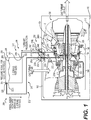
- FIG. 1 A partial, cross-sectional view of a single shaft, twin centrifugal compressor, three stage axial turbine, with a reverse flow annular combustor is shown as an exemplary gas turbine engine 100 in FIG. 1 .
- the gas turbine engine 100 is for use with an aircraft 99, although other arrangements and uses may be provided.
- the gas turbine engine 100 may be, for example, an industrial, automotive, or Aerospace gas turbine such as a generator or compressor set, an auxiliary power unit, a turboshaft, a turboprop, or a turbofan system.
- one or more cooling passages of a combustion chamber of the gas turbine engine 100 may be cleaned by a cooling passage cleaning system 200, 400 of the present disclosure to remove accumulated fine particles, such as fine sand and dust particles, from the one or more cooling features or passages, such as one or more effusion holes.
- a cooling passage cleaning system 200, 400 of the present disclosure to remove accumulated fine particles, such as fine sand and dust particles, from the one or more cooling features or passages, such as one or more effusion holes.
- the gas turbine engine 100 includes an inlet section 102, a compressor section 104, a combustor section 106, a turbine section 108, and an exhaust section 110. Air is directed by the inlet section 102 into the compressor section 104.
- the compressor section 104 includes two centrifugal compressor stages connected to a three stage axial turbine.
- the compressor may be axial, centrifugal or a combination of axial and centrifugal stages.
- the compressor section 104 may be of a single shaft or multiple shaft configuration.
- the compressor section 104 raises the pressure of the air and directs a majority of the high pressure air into the combustor section 106 via a diffuser and deswirl system 155.
- a fraction of the compressed air bypasses the combustor section 106 and is used to cool, among other components, vanes and blades in the turbine section 108.
- the combustor section 106 includes a plenum or combustor plenum 136 receiving the air from the compressor section 104, a fuel delivery system 138 and combustion chamber 124, in which the high pressure air is mixed with fuel and combusted. The high-temperature combusted air is then directed into the turbine section 108.
- the turbine section 108 includes three turbines disposed in axial flow stages. However, it will be appreciated that the number of turbines, and/or the configurations thereof, may vary.
- work is extracted from the high pressure and temperature air exiting the combustor section 106.
- the power generated by the turbine stages drive equipment in the gas turbine engine, compressors, etc. and provide shaft power to other elements of the aircraft 99; generators, pumps, etc.
- the combustor plenum 136 is upstream from the combustion chamber 124 and supplies the combustion chamber 124 with at least air received from the diffuser and deswirl system 155.
- the combustor plenum 136 is upstream from the combustion chamber 124 and is downstream from the diffuser and deswirl system 155.
- the combustor plenum 136 is defined by an annular outer wall 136a, which is spaced apart from a first annular outer wall 140 of the combustion chamber 124 to define a fluid flow passage for the air received from the diffuser and deswirl system 155.
- the fuel delivery system 138 of the combustor section 106 includes one or more fuel delivery components, such as one or more fuel injectors 168.
- the combustion chamber 124 is defined between the first annular outer wall 140, a second annular inner wall 142 and an interconnecting wall or dome 144.
- the first annular outer wall 140 is positioned substantially opposite the second annular inner wall 142 to define the combustion chamber 124.
- the first annular outer wall 140 and the second annular inner wall 142 each define a plurality of cooling features or passages 146 and a plurality of inlet bores 148 about a circumference of the first annular outer wall 140 and the second annular inner wall 142.
- the first annular outer wall 140 and the second annular inner wall 142 each extend from a respective first end 150, 152 to a respective second end 154, 156.
- the dome 144 is substantially U-shaped, and is coupled to the first end 150, 152 of each of the first annular wall outer 140 and the second annular inner wall 142 to enclose the combustion chamber 124.
- the plurality of cooling passages 146 is a plurality of effusion cooling holes, which are each defined through the first annular outer wall 140 and the second annular inner wall 142.
- the plurality of cooling passages 146 may be defined through the first annular outer wall 140 and the second annular inner wall 142 to enable a portion of the air from the compressor section 104 to pass through the first annular outer wall 140 and the second annular inner wall 142 to cool each of the first annular outer wall 140 and the second annular inner wall 142.
- air is received from the diffuser and deswirl system 155, which is downstream of the compressor section 104, and the air flows from the compressor section 104 along a path indicated by arrows A.
- the plurality of cooling passages 146 may be defined through each of the first annular outer wall 140 and the second annular inner wall 142 in various patterns and spacings, which are predetermined based on the cooling requirements of the first annular outer wall 140 and the second annular inner wall 142.
- the cooling passage 146 is defined though the first annular outer wall 140, and has an inlet 158, an outlet 160 and a passageway 162 defined by the first annular outer wall 140.
- the plurality of cooling passages 146 associated with the second annular inner wall 142 are substantially similar to the one of the plurality of cooling passages 146 illustrated in FIG. 3 .
- the inlet 158 receives a portion of the pressurized air from the compressor section 104, which flows through the passageway 162 and exits into the combustion chamber 124 via the outlet 160, as indicated by the arrow A.
- the flow of pressurized air through the passageway 162 cools the first annular outer wall 140 or the second annular inner wall 142.
- the fine particles may be drawn into the gas turbine engine 100 via the inlet section 102 ( FIG. 1 ).
- coarser particles that may also be ingested through the inlet section 102 are reduced to fine particles as they interact with the compressor components and along with the ingested fine particles pass through the compressor section 104 ( FIG. 1 ).
- the fine particles such as the fine sand and dust particles, may accumulate at the inlet 158 and within the passageway 162 near the inlet 158.
- the accumulation of fine particles 164 may at least partially or substantially completely obscure the inlet 158, such that an amount of pressurized air that enters the passageway 162 for cooling is reduced or substantially eliminated. This reduction in the pressurized cooling air may reduce the life of the combustion chamber 124.
- the cooling passage cleaning system 200, 400 substantially removes the accumulation of fine particles 164, which thereby restores the flow of pressurized cooling air through each of the plurality of cooling passages 146.
- the plurality of inlet bores 148 are defined through the first annular outer wall 140 and the second annular inner wall 142 near, adjacent to or at the respective first end 150, 152.
- the plurality of inlet bores 148 each generally have a diameter, which is greater than a diameter of each of the plurality of cooling passages 146.
- the plurality of inlet bores 148 enable the air from the compressor section 104 to enter the combustion chamber 124 for combustion.
- the first annular outer wall 140 also defines a plurality of fuel injector bores 166 about the circumference of the first annular outer wall 140 near, adjacent to or at the first end 150.
- Each of the fuel injector bores 166 receives a respective fuel delivery component, such as the fuel injector 168.
- each of the plurality of fuel injector bores 166 are spaced apart by one or more of the plurality of inlet bores 148.
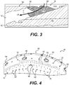
- FIG. 4 a top view of a portion of the first annular outer wall 140 of the combustion chamber 124 is shown. In this example, the fuel injector 168 is removed from each of the plurality of fuel injector bores 166 for clarity.
- the plurality of fuel injector bores 166 are spaced apart by a respective one or more of the plurality of inlet bores 148.
- the first annular outer wall 140 includes a first plurality of inlet bores 148' and a second plurality of inlet bores 148" spaced apart from each other about the circumference of the first annular outer wall 140. It should be understood, however, that the first annular outer wall 140 may have any predetermined arrangement of inlet bores 148.
- the cooling passage cleaning system 200 includes a first or inlet conduit 202, a second or outlet conduit 204, at least one valve 206 and a particle chamber or chamber 208.
- the at least one valve 206 includes a first valve 206a and a second valve 206b.
- the cooling passage cleaning system 200 may also include a controller and a user device, which is in communication with the controller to receive input commands to open or close the at least one valve 206 for cleaning the accumulated fine particles 164 from each of the plurality of cooling passages 146 of the combustion chamber 124.
- the first or inlet conduit 202 is coupled to the chamber 208 and to the gas turbine engine 100.
- the inlet conduit 202 fluidly couples the chamber 208 to the diffuser and deswirl system 155 of the gas turbine engine 100 to enable the introduction of a cleaning fluid 216 ( FIG. 2 ) into the gas turbine engine 100.
- the inlet conduit 202 includes a first conduit section 218, a second conduit section 220 and a plurality of couplings 222a-d. It will be understood, however, that the inlet conduit 202 may comprise a single conduit between the chamber 208 and the diffuser and deswirl system 155, if desired.
- the first conduit section 218 is a flexible pneumatic hose, and includes a first inlet end 224 and a first outlet end 226.
- the first inlet end 224 includes the coupling 222a, which fluidly couples the first inlet end 224 to the chamber 208.
- the first outlet end 226 includes the coupling 222b, which fluidly couples the first conduit section 218 to the first valve 206a.
- the first valve 206a is movable between an opened position and a closed position to enable the first conduit section 218 to be fluidly coupled to the second conduit section 220.
- the second conduit section 220 is disposed substantially entirely or wholly within the aircraft 99, and is a flexible pneumatic hose.
- the second conduit section 220 includes a second inlet end 228 and a second outlet end 230.
- the second inlet end 228 includes the coupling 222c, which fluidly couples the second conduit section 220 to the first valve 206a such that movement of the first valve 206a to the opened position fluidly couples the second conduit section 220 to the first conduit section 218.
- the second outlet end 230 includes the coupling 222d, which fluidly couples the second conduit section 220 to an end wall 232 of the diffuser and deswirl system 155.
- the second conduit section 220 is coupled to the end wall 232 of the diffuser and deswirl system 155 such that the inlet conduit 202 is downstream from the compressor section 104; and upstream from the combustion chamber 124.
- the coupling 222d may be received within a bore defined through the end wall 232 or may be disposed about a bore defined through the end wall 232 to enable fluid communication between the chamber 208 and the diffuser and deswirl system 155 via the end wall 232.
- each of the couplings 222a-d are pneumatic quick disconnect couplings that enable fluid communication between the chamber 208, the first conduit section 218, the second conduit section 220, the first valve 206a and the diffuser and deswirl system 155. It should be noted that while the couplings 222a-d are described and illustrated herein as comprising quick disconnect couplings, any coupling that enables fluid communication between the chamber 208 and the diffuser and deswirl system 155 via the inlet conduit 202 may be employed.
- the second or outlet conduit 204 is coupled to the gas turbine engine 100 and to the chamber 208.
- the outlet conduit 204 fluidly couples the combustor plenum 136 of the gas turbine engine 100 to the chamber 208 to enable the chamber 208 to be pressurized with air from the gas turbine engine 100.
- the outlet conduit 204 includes a third conduit section 240, a fourth conduit section 242 and a second plurality of couplings 244a-d. It will be understood, however, that the outlet conduit 204 may comprise a single conduit between the combustor plenum 136 and the chamber 208, if desired.
- the third conduit section 240 is disposed substantially entirely or wholly within the aircraft 99, and is a flexible pneumatic hose.
- the third conduit section 240 includes a third inlet end 246 and a third outlet end 248.
- the third inlet end 246 includes the coupling 244a, which fluidly couples the third inlet end 246 to the combustor plenum 136.
- the coupling 244a may be received within a bore defined through the combustor plenum 136 or may be disposed about a bore 137 defined through the combustor plenum 136 to enable fluid communication between the combustor plenum 136 and the chamber 208.
- the third inlet end 246 is coupled to the combustor plenum 136 so as to be downstream from the second outlet end 230 in the direction of airflow A through the gas turbine engine 100 as shown in FIG. 2 .
- the inlet conduit 202 is coupled to the combustor plenum 136 so as to be upstream from the outlet conduit 204 in the direction of airflow A through the gas turbine engine 100.
- the third conduit section 240 is coupled to the combustor plenum 136 such that the outlet conduit 204 is also downstream from the compressor section 104 and upstream from the combustion chamber 124.
- the third outlet end 248 includes the coupling 244b, which fluidly couples the third conduit section 240 to the second valve 206b.
- the second valve 206b is movable between an opened position and a closed position to enable the third conduit section 240 to be fluidly coupled to the fourth conduit section 242.
- the fourth conduit section 242 is a flexible pneumatic hose, and includes a fourth inlet end 250 and a fourth outlet end 252.
- the fourth inlet end 250 includes the coupling 244c, which fluidly couples the fourth conduit section 242 to the second valve 206b such that movement of the second valve 206b to the opened position fluidly couples the fourth conduit section 242 to the third conduit section 240.
- the fourth outlet end 252 includes the coupling 244d, which fluidly couples the fourth conduit section 242 to the chamber 208.
- the fourth conduit section 242 is coupled to the chamber 208 to provide the chamber 208 with pressurized air bled from the combustor plenum 136, downstream from the compressor section 104 and upstream from the combustion chamber 124.
- each of the couplings 244a-d are pneumatic quick disconnect couplings that enable fluid communication between the chamber 208, the third conduit section 240, the fourth conduit section 242, the second valve 206b and the diffuser and deswirl system 155. It should be noted that while the couplings 244a-d are described and illustrated herein as comprising quick disconnect couplings, any coupling that enables fluid communication between the chamber 208 and the combustor plenum 136 via the outlet conduit 204 may be employed.
- the at least one valve 206 includes the first valve 206a and the second valve 206b, which are coupled to an installation interface 259 adjacent to the gas turbine engine 100.
- the first valve 206a and the second valve 206b are each one-way valves.
- the first valve 206a is fluidly coupled to the first conduit section 218 and is fluidly coupled to the second conduit section 220 to selectively enable pressurized fluid, with entrained particles, to flow from the chamber 208 into the gas turbine engine 100.
- the second valve 206b is fluidly coupled to the fourth conduit section 242 of the outlet conduit 204 to selectively enable the pressurized air bled from the combustor plenum 136 to flow into the chamber 208.
- the first valve 206a and the second valve 206b are each manual one-way two-port valves, such that user input to a lever or actuator coupled to the respective one of the first valve 206a and the second valve 206b moves a valve member or disc associated with the respective one of the first valve 206a and the second valve 206b between the opened and closed positions.
- a user may manipulate the lever or actuator, by rotating the lever or actuator for example, to move the valve member or disc from an opened position, in which fluid flows through the respective one of the first valve 206a and the second valve 206b; and a closed position, in which fluid is inhibited or prevented from flowing through the respective one of the first valve 206a and the second valve 206b.
- first valve 206a and the second valve 206b are described herein as being manually actuated, it will be understood that one or both of the first valve 206a and the second valve 206b may be responsive to control signals received from a controller to move the valve member or disc of the first valve 206a and the second valve 206b into the opened or closed positions.
- the chamber 208 includes housing 260 having a chamber inlet 262 and a chamber outlet 264.
- the chamber inlet 262 is fluidly coupled to the outlet conduit 204 to receive the pressurized air bled from the combustor plenum 136 of the gas turbine engine 100.
- the chamber outlet 264 is fluidly coupled to the inlet conduit 202 to supply the inlet conduit 202 with the cleaning fluid 216.
- the housing 260 substantially encloses a
- the chamber inlet 262 is defined through one of the plurality of sidewalls at or near the bottom side of the housing 260
- the chamber outlet 264 is defined through one of the plurality of sidewalls at or near the top side of the housing 260 in a vertical direction, such that as the pressurized air enters the chamber 208 it causes at least a portion of the plurality of particles 266 to be airborne. These airborne particles become entrained within pressurized air, which exits the chamber 208 via the chamber outlet 264.
- "entrain” denotes to draw in and transport solid particles by a flow of a fluid.
- the housing 260 is composed of any metal, metal alloy or polymer that is configured to withstand a pressure of the pressurized air received from the gas turbine engine 100 or external pressurized fluid source 408 ( FIGS. 6-7 ). In one example, the housing 260 is configured to withstand about 276 kilopascal (40 pounds per square inch (psi)) higher than a maximum discharge operating pressure of the compressor section 104 associated with the gas turbine engine 100.
- the housing 260 withstands a pressure from about 557 kilopascal (5.5 atmosphere (atm)) to about 6078 kilopascal (60 atmosphere (atm)). In this example, the housing 260 withstands a pressure of at least about 1064 kilopascal (10.5 atmosphere (atm)).
- the cleaning fluid 216 comprises a portion of the plurality of particles 266, which are entrained within the pressurized air bled from the combustor plenum 136 of the gas turbine engine 100 as the pressurized air flows through the chamber 208.
- the cleaning fluid 216 supplied by the inlet conduit 202 through the end wall 232 of the diffuser and deswirl system 155 is a pressurized fluid with an entrained portion of the plurality of particles 266.
- the plurality of particles 266 is a plurality of particles of aluminum oxide, Al 2 O 3 , which have a predetermined particle size distribution.
- the cleaning fluid 216 supplied by the inlet conduit 202 through the end wall 232 of the diffuser and deswirl system 155 is a pressurized fluid with an entrained portion of the plurality of particles 266.
- the plurality of particles 266 is a plurality of particles of aluminum oxide, Al 2 O 3 , which have a predetermined particle size distribution.
- the size distribution of the particles of aluminum oxide is between about 3.5 micrometers to about 200 micrometers.
- the size distribution of the particles of aluminum oxide is between about 3.5 micrometers to about 80 micrometers.
- the plurality of particles 266 is particles of aluminum oxide with a size distribution between about 40 micrometers to about 80 micrometers.
- aluminum oxide is chemically inert, any particles remaining after cleaning will not adversely affect the operation of the gas turbine engine 100.
- the size distribution of the plurality of particles 266 also reduces potential erosion to downstream components, while effectively cleaning the plurality of cooling passages 146.
- the size distribution of the plurality of particles 266 causes the particles to separate from the pressurized air and enter the inlets 158 of respective ones of the plurality of cooling passages 146.
- the plurality of particles 266 impinge upon the accumulated fine particles 164 ( FIG. 1 ), and dislodge the accumulated fine particles 164 from the respective plurality of cooling passages 146, thereby cleaning the plurality of cooling passages 146.
- an exemplary method 300 for cleaning the one or more cooling passages 146 of the combustion chamber 124 is shown.
- the method begins at 302.
- the inlet conduit 202 is fluidly coupled between the chamber outlet 264 and the end wall 232 of the diffuser and deswirl system 155.
- the first conduit section 218 is coupled to the chamber outlet 264, via the coupling 222a, and the first conduit section 218 is fluidly coupled to the second conduit section 220 via the first valve 206a.
- the first valve 206a is coupled to the first conduit section 218 by the coupling 222b and the second conduit section 220 is coupled to the first valve 206a by the coupling 222c at the installation interface 259 while the first valve 206a is in the closed position.
- the second conduit section 220 is fluidly coupled to the end wall 232 of the diffuser and deswirl system 155 via the coupling 222d, such that the second conduit section 220 is contained substantially wholly within the gas turbine engine 100.
- the outlet conduit 204 is fluidly coupled between the combustor plenum 136 and the chamber inlet 262 such that the outlet conduit 204 is downstream from the inlet conduit 202.
- the third conduit section 240 is coupled to the combustor plenum 136, via the coupling 244a, and the third conduit section 240 is fluidly coupled to the fourth conduit section 242 via the second valve 206b.
- the second valve 206b is coupled to the third conduit section 240 by the coupling 244b and the fourth conduit section 242 is coupled to the second valve 206b by the coupling 244c at the installation interface 259 while the second valve 206b is in the closed position.
- the third conduit section 240 is contained substantially wholly within the gas turbine engine 100.
- the fourth conduit section 242 is fluidly coupled to the chamber inlet 262 via the coupling 244d.
- the gas turbine engine 100 is started.
- the starting of the gas turbine engine 100 may be performed via known ways, such as an input to a controller associated with the gas turbine engine 100.
- the second valve 206b is moved from the closed position to the opened position, by moving the lever or actuator coupled to the second valve 206b to manually move the valve member or disc to open the second valve 206b and enable fluid to flow through the second valve 206b.
- the pressurized fluid bled from the combustor plenum 136 is received through the outlet conduit 204. Stated another way, at 312, the pressurized fluid, in this example, pressurized air, is received from a source, which in this example, is the combustor plenum 136 of the gas turbine engine 100.
- the pressurized fluid or air is directed through the chamber inlet 262 such that a portion of the plurality of particles 266 within the chamber 208 is entrained within the pressurized fluid or air.
- the first valve 206a is moved from the closed position to the opened position, by moving the lever or actuator coupled to the first valve 206a to manually move the valve member or disc to open the first valve 206a and enable fluid to flow through the first valve 206a.
- the pressurized fluid with the entrained portion of the plurality of particles i.e.
- the cleaning fluid 216) is injected downstream from the compressor section 104 and upstream from the combustion chamber 124 through the end wall 232 of the diffuser and deswirl system 155 to clean the one or more cooling passages 146 of the combustion chamber 124.
- the method ends at 320.
- the cleaning of the one or more cooling passages 146 may be ended at any time, by manually moving the first valve 206a from the opened position to the closed position, by moving the lever or actuator coupled to the valve member or disc, for example.
- the second valve 206b may then be moved from the opened position to the closed position, by moving the lever or actuator coupled to the valve member or disc, for example.
- the chamber 208 may be disconnected from the installation interface 259 by disconnecting the coupling 222b from the first valve 206a and the coupling 244c from the second valve 206b.
- cooling passage cleaning system 200 as described herein is not limited to the configuration shown in FIGS. 1-5 .
- a cooling passage cleaning system 400 is shown for use with the gas turbine engine 100.
- the cooling passage cleaning system 400 is similar to the cooling passage cleaning system 200 discussed with regard to FIGS. 1-5 , only the differences between the cooling passage cleaning system 200 and the cooling passage cleaning system 400 will be discussed in great detail herein, and the same reference numerals will be used to denote the same or similar components.
- the cooling passage cleaning system 400 includes a first or inlet conduit 402, a second or outlet conduit 404, the at least one valve 206, the particle chamber or chamber 208 and an external pressurized fluid source 408.
- the cooling passage cleaning system 400 may also include a controller and a user device, which is in communication with the controller to receive input commands to open or close the first valve 206a and the second valve 206b for cleaning the accumulated fine particles 164 from each of the plurality of cooling passages 146 of the combustion chamber 124.
- the first or inlet conduit 402 is coupled to the chamber 208 and to the gas turbine engine 100.
- the inlet conduit 402 fluidly couples the chamber 208 to the diffuser and deswirl system 155 of the gas turbine engine 100 to enable the introduction of a cleaning fluid 216' into the gas turbine engine 100.
- the inlet conduit 402 includes the first conduit section 218, a second conduit section 420 and the plurality of couplings 222a-d. It will be understood, however, that the inlet conduit 402 may comprise a single conduit between the chamber 208 and the diffuser and deswirl system 155, if desired.
- the second conduit section 420 is disposed substantially entirely or wholly within the aircraft 99, and is a flexible pneumatic hose.
- the second conduit section 420 includes the second inlet end 228 and a second outlet end 430.
- the second inlet end 228 includes the coupling 222c, which fluidly couples the second conduit section 420 to the first valve 206a such that movement of the first valve 206a to the opened position fluidly couples the second conduit section 420 to the first conduit section 218.
- the second outlet end 430 includes the coupling 222d, which fluidly couples the second conduit section 420 to the end wall 232 of the diffuser and deswirl system 155.
- the second conduit section 420 is coupled to the end wall 232 of the diffuser and deswirl system 155 such that the inlet conduit 402 is downstream from the compressor section 104; and upstream from the combustion chamber 124.
- the coupling 222d may be received within a bore defined through the end wall 232 or may be disposed about a bore defined through the end wall 232 to enable fluid communication between the chamber 208 and the diffuser and deswirl system 155 via the end wall 232.
- the position of the second outlet end 430 in FIG. 7 is merely an example.
- the second outlet end 403 may be coupled to the gas turbine engine 100 at any location between the end wall 232 and the combustor plenum 136.
- the second or outlet conduit 404 is coupled to the external pressurized fluid source 408 and to the chamber 208.
- the outlet conduit 404 fluidly couples the external pressurized fluid source 408 to the chamber 208 to enable the chamber 208 to be pressurized with air from the external pressurized fluid source 408.
- the outlet conduit 404 includes a third conduit section 440, the fourth conduit section 242 and the second plurality of couplings 244a-d It will be understood, however, that the outlet conduit 404 may comprise a single conduit between the external pressurized fluid source 408 and the chamber 208, if desired.
- the third conduit section 440 is a flexible pneumatic hose.
- the third conduit section 440 includes a third inlet end 446 and the third outlet end 248.
- the third inlet end 446 includes the coupling 244a, which fluidly couples the third inlet end 446 to the external pressurized fluid source 408.
- the coupling 244a may be coupled to a coupling 408a of the external pressurized fluid source 408 to enable fluid communication between the external pressurized fluid source 408 and the chamber 208.
- the third outlet end 248 includes the coupling 244b, which fluidly couples the third conduit section 440 to the second valve 206b.
- the fourth conduit section 242 is coupled to the chamber 208 to provide the chamber 208 with pressurized air from the external pressurized fluid source 408.
- the external pressurized fluid source 408 is a source of pressurized air, which is external to or remote from the gas turbine engine 100.
- the external pressurized fluid source 408 is a compressor, which is capable of compressing the air to a pressure of about 276 kilopascal (40 pounds per square inch (psi)) higher than a maximum discharge operating pressure of the compressor section 104 associated with the gas turbine engine 100.
- the external pressurized fluid source 408 compresses the air to a pressure ranging from about 557 kilopascal (5.5 atmosphere (atm)) to about 6078 kilopascal (60 atmosphere (atm)).
- the external pressurized fluid source 408 compresses the air to at least about 1064 kilopascal (10.5 atmosphere (atm)).
- the external pressurized fluid source 408 includes the coupling 408a at an outlet 448.
- the coupling 408a is a pneumatic quick disconnect coupling that enables fluid communication between the third conduit section 440 and the external pressurized fluid source 408. It should be noted that while the coupling 408a is described and illustrated herein as comprising a quick disconnect coupling, any coupling that enables fluid communication between the chamber 208 and the external pressurized fluid source 408 via the outlet conduit 404 may be employed.
- the external pressurized fluid source 408 includes the coupling 408a at an outlet 448.
- the coupling 408a is a pneumatic quick disconnect coupling that enables fluid communication between the third conduit section 440 and the external pressurized fluid source 408. It should be noted that while the coupling 408a is described and illustrated herein as comprising a quick disconnect coupling, any coupling that enables fluid communication between the chamber 208 and the external pressurized fluid source 408 via the outlet conduit 404 may be employed.
- the cleaning fluid 216' comprises a portion of the plurality of particles 266, which are entrained within the pressurized air from the external pressurized fluid source 408 as the pressurized air flows through the chamber 208.
- the cleaning fluid 216' supplied by the inlet conduit 402 through the end wall 232 of the diffuser and deswirl system 155 is a pressurized fluid with an entrained portion of the plurality of particles 266.
- an exemplary method 500 for cleaning the one or more cooling passages 146 of the combustion chamber 124 is shown.
- the method begins at 502.
- the inlet conduit 402 is fluidly coupled between the chamber outlet 264 and the end wall 232 of the diffuser and deswirl system 155.
- the first conduit section 218 is coupled to the chamber outlet 264, via the coupling 222a, and the first conduit section 218 is fluidly coupled to the second conduit section 420 via the first valve 206a.
- the first valve 206a is coupled to the first conduit section 218 by the coupling 222b and the second conduit section 420 is coupled to the first valve 206a by the coupling 222c while the first valve 206a is in the closed position.
- the second conduit section 420 is fluidly coupled to the end wall 232 of the diffuser and deswirl system 155 via the coupling 222d, such that the second conduit section 420 is contained substantially wholly within the gas turbine engine 100.
- the outlet conduit 404 is fluidly coupled between the external pressurized fluid source 408 and the chamber inlet 262.
- the third conduit section 440 is coupled to the external pressurized fluid source 408, via the coupling 244a, and the third conduit section 440 is fluidly coupled to the fourth conduit section 242 via the second valve 206b.
- the second valve 206b is coupled to the third conduit section 440 by the coupling 244b and the fourth conduit section 242 is coupled to the second valve 206b by the coupling 244c while the second valve 206b is in the closed position.
- the fourth conduit section 242 is fluidly coupled to the chamber inlet 262 via the coupling 244d.
- the gas turbine engine 100 is started.
- the starting of the gas turbine engine 100 may be performed via known ways, such as an input to a controller associated with the gas turbine engine 100.
- the second valve 206b is moved from the closed position to the opened position, by moving the lever or actuator coupled to the second valve 206b to manually move the valve member or disc to open the second valve 206b and enable fluid to flow through the second valve 206b.
- the pressurized fluid from the external pressurized fluid source 408 is received through the outlet conduit 204.
- the pressurized fluid in this example, pressurized air
- a source which in this example, is the external pressurized fluid source 408 that is remote from the gas turbine engine 100.
- the pressurized fluid or air is directed through the chamber inlet 262 such that a portion of the plurality of particles 266 within the chamber 208 is entrained within the pressurized fluid or air.
- the first valve 206a is moved from the closed position to the opened position, by moving the lever or actuator coupled to the first valve 206a to manually move the valve member or disc to open the first valve 206a and enable fluid to flow through the first valve 206a.
- the pressurized fluid with the entrained portion of the plurality of particles i.e.
- the cleaning fluid 216' is injected downstream from the compressor section 104 and upstream from the combustion chamber 124 through the end wall 232 of the diffuser and deswirl system 155 to clean the one or more cooling passages 146 of the combustion chamber 124.
- the method ends at 520.
- the cleaning of the one or more cooling passages 146 may be ended at any time, by manually moving the first valve 206a from the opened position to the closed position, by moving the lever or actuator coupled to the valve member or disc, for example.
- the second valve 206b may then be moved from the opened position to the closed position, by moving the lever or actuator coupled to the valve member or disc, for example.
- the chamber 208 may be disconnected from the gas turbine engine 100 by disconnecting the coupling 222b from the first valve 206a.
- the cooling passage cleaning system 200, 400 removes the accumulated fine particles 164 ( FIG. 3 ) from the plurality of cooling passages 146 without requiring the gas turbine engine 100 to be uninstalled from the aircraft 99. This reduces maintenance time and cost. Moreover, as the cooling passage cleaning system 200 may bleed air from the combustor plenum 136 of the gas turbine engine 100 while the gas turbine engine 100 is running, the cooling passage cleaning system 200 may not require a separate pressure source, which may enable the cooling passage cleaning system 200 to operate in rural or remote locations.
- the use of aluminum oxide for the plurality of particles 266, which is inert, enables the plurality of cooling passages 146 to be cleaned by the cooling passage cleaning system 200, 400 and any particle residue to be safely exhausted by the operation of the gas turbine engine 100.
- the size distribution of the plurality of particles 266 also enables the plurality of cooling passages 146 to be cleaned by the cooling passage cleaning system 200, 400 substantially without erosion to downstream components, such as the turbines of the turbine section 108.
- cooling passage cleaning system 200, 400 as described herein is not limited to the configuration shown in FIGS. 1-8 .
- the cooling passage cleaning system 200, 400 is described and illustrated herein as comprising a single cooling passage cleaning system 200, 400, a disclosure as set forth in the appended claims.
Landscapes
- Engineering & Computer Science (AREA)
- Chemical & Material Sciences (AREA)
- Combustion & Propulsion (AREA)
- Mechanical Engineering (AREA)
- General Engineering & Computer Science (AREA)
- Turbine Rotor Nozzle Sealing (AREA)
Description
- The present disclosure generally relates to gas turbine engines, and more particularly relates to a system and method for cleaning cooling passages, such as effusion holes, in a combustion chamber of a gas turbine engine.
- Gas turbine engines may be employed to power various devices. For example, a gas turbine engine may be employed to power a mobile platform, such as an aircraft, rotorcraft, etc. In the example of the gas turbine engine powering a mobile platform, certain operating environments, such as desert operating environments, may cause the gas turbine engine to ingest fine sand and dust particles. The ingestion of the fine sand and dust particles may obstruct one or more cooling passages associated with a portion of the gas turbine engine, such as the combustor. The obstruction of the one or more cooling passages may reduce an effectiveness of a cooling of the combustion chamber, which may reduce a life expectancy for the combustion chamber.
- Accordingly, it is desirable to provide a system and a method for cleaning cooling passages in a combustion chamber, which removes fine particles, such as fine sand and dust particles from the one or more cooling passages to enable effective cooling of the combustion chamber. Furthermore, other desirable features and characteristics of the present invention will become apparent from the subsequent detailed description and the appended claims, taken in conjunction with the accompanying drawings and the foregoing technical field and background.
-
JP2001214755A -
CH660056A5 - According to the invention, a method as set forth in claim 1 and a system as set forth in claim 4 for cleaning one or more cooling passages associated with a combustion chamber of a gas turbine engine are provided. The gas turbine engine includes a compressor section upstream from the combustion chamber and a diffuser and deswirl system downstream from the compressor section. The system includes an external source of a pressurized fluid remote from the gas turbine engine. The system also includes a chamber including a plurality of particles having a predetermined particle size distribution. The chamber having an inlet in fluid communication with the source to receive the pressurized fluid and an outlet in fluid communication with an end wall of the diffuser and deswirl system. At least a portion of the plurality of particles entrained in the pressurized fluid flows through the chamber to clean the one or more cooling passages associated with the combustion chamber.
- The examples and embodiments will hereinafter be described in conjunction with the following drawing figures, wherein like numerals denote like elements, and wherein:
-
FIG. 1 is a schematic cross-sectional illustration of a gas turbine engine including a cooling passage cleaning system according to an example not falling under the scope of the claims; -
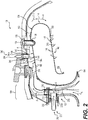
FIG. 2 is a detail cross-sectional illustration of a portion of the gas turbine engine ofFIG. 1 , identified at 2 inFIG. 1 , which includes a portion of the cooling passage cleaning system; -
FIG. 3 is a cross-sectional view of one of a plurality of cooling passages associated with a combustion chamber of the gas turbine engine ofFIG. 1 , taken along line 3-3 ofFIG. 4 , which illustrates an accumulation of fine particles within the one of the plurality of cooling passages; -
FIG. 4 is a top view of a first wall of a combustion chamber of the gas turbine engine ofFIG. 1 , which illustrates a portion of the plurality of cooling passages; -
FIG. 5 is a flow chart illustrating an exemplary method for cleaning the plurality of cooling passages of the combustion chamber of the gas turbine engine ofFIG. 1 not falling under the scope of the claims; -
FIG. 6 is a schematic cross-sectional illustration of the gas turbine engine including another cooling passage cleaning system according to the invention; -
FIG. 7 is a detail cross-sectional illustration of a portion of the gas turbine engine ofFIG. 6 , identified at 7 inFIG. 6 , which includes a portion of the cooling passage cleaning system; and -
FIG. 8 is a flow chart illustrating an exemplary method for cleaning the plurality of cooling passages of the combustion chamber of the gas turbine engine with the cooling passage cleaning system ofFIG. 6 . - The following detailed description is merely exemplary in nature and is not intended to limit the application and uses. Furthermore, there is no intention to be bound by any expressed or implied theory presented in the preceding technical field, background, brief summary or the following detailed description. In addition, those skilled in the art will appreciate that embodiments of the present disclosure may be practiced in conjunction with any component of a gas turbine engine that would benefit from the removal of accumulated fine particles, and that the removal of the accumulated fine particles from the combustion chamber described herein is merely one exemplary embodiment according to the present disclosure. Moreover, while the system and method for cleaning cooling passages is described herein as being used with a combustion chamber of a gas turbine engine onboard a mobile platform or vehicle, such as a bus, motorcycle, train, motor vehicle, marine vessel, aircraft, rotorcraft and the like, the various teachings of the present disclosure may be used with a gas turbine engine associated with a stationary platform, or may be used to address similar cleaning requirements in other types of systems. Further, it should be noted that many alternative or additional functional relationships or physical connections may be present in an embodiment of the present disclosure. In addition, while the figures shown herein depict an example with certain arrangements of elements, additional intervening elements, devices, features, or components may be present in an actual embodiment. It should also be understood that the drawings are merely illustrative and may not be drawn to scale. Those skilled in the art will appreciate that embodiments of the present disclosure may be practiced in conjunction with any number of systems, and that the systems described herein is merely exemplary embodiments of the present disclosure. Furthermore, the connecting lines shown in the various figures contained herein are intended to represent example functional relationships and/or physical couplings between the various elements.
- A partial, cross-sectional view of a single shaft, twin centrifugal compressor, three stage axial turbine, with a reverse flow annular combustor is shown as an exemplary
gas turbine engine 100 inFIG. 1 . In the depicted example falling outside the scope of the claims, thegas turbine engine 100 is for use with anaircraft 99, although other arrangements and uses may be provided. Thegas turbine engine 100 may be, for example, an industrial, automotive, or Aerospace gas turbine such as a generator or compressor set, an auxiliary power unit, a turboshaft, a turboprop, or a turbofan system. As will be discussed herein, one or more cooling passages of a combustion chamber of thegas turbine engine 100 may be cleaned by a coolingpassage cleaning system gas turbine engine 100. Moreover, removing the accumulated fine particles from the one or more cooling passages improves a life expectancy of the combustion chamber, may increase the time interval for required maintenance and also may reduce replacement and repair costs associated with the combustion chamber. - In this example, the
gas turbine engine 100 includes aninlet section 102, acompressor section 104, acombustor section 106, aturbine section 108, and anexhaust section 110. Air is directed by theinlet section 102 into thecompressor section 104. In the embodiment ofFIG. 1 , thecompressor section 104 includes two centrifugal compressor stages connected to a three stage axial turbine. However, in other embodiments, the compressor may be axial, centrifugal or a combination of axial and centrifugal stages. Thecompressor section 104 may be of a single shaft or multiple shaft configuration. In the depicted example, thecompressor section 104 raises the pressure of the air and directs a majority of the high pressure air into thecombustor section 106 via a diffuser anddeswirl system 155. A fraction of the compressed air bypasses thecombustor section 106 and is used to cool, among other components, vanes and blades in theturbine section 108. - In the example of
FIG. 1 , thecombustor section 106 includes a plenum orcombustor plenum 136 receiving the air from thecompressor section 104, afuel delivery system 138 andcombustion chamber 124, in which the high pressure air is mixed with fuel and combusted. The high-temperature combusted air is then directed into theturbine section 108. In this example, theturbine section 108 includes three turbines disposed in axial flow stages. However, it will be appreciated that the number of turbines, and/or the configurations thereof, may vary. In this example, work is extracted from the high pressure and temperature air exiting thecombustor section 106. The power generated by the turbine stages drive equipment in the gas turbine engine, compressors, etc. and provide shaft power to other elements of theaircraft 99; generators, pumps, etc. - With reference to
FIG. 2 , a portion of thecombustor section 106 of the exemplarygas turbine engine 100 ofFIG. 1 is shown in greater detail. In this example, thecombustor plenum 136 is upstream from thecombustion chamber 124 and supplies thecombustion chamber 124 with at least air received from the diffuser anddeswirl system 155. Thus, thecombustor plenum 136 is upstream from thecombustion chamber 124 and is downstream from the diffuser anddeswirl system 155. Thecombustor plenum 136 is defined by an annularouter wall 136a, which is spaced apart from a first annularouter wall 140 of thecombustion chamber 124 to define a fluid flow passage for the air received from the diffuser anddeswirl system 155. Thefuel delivery system 138 of thecombustor section 106 includes one or more fuel delivery components, such as one ormore fuel injectors 168. - The
combustion chamber 124 is defined between the first annularouter wall 140, a second annularinner wall 142 and an interconnecting wall ordome 144. The first annularouter wall 140 is positioned substantially opposite the second annularinner wall 142 to define thecombustion chamber 124. The first annularouter wall 140 and the second annularinner wall 142 each define a plurality of cooling features orpassages 146 and a plurality of inlet bores 148 about a circumference of the first annularouter wall 140 and the second annularinner wall 142. The first annularouter wall 140 and the second annularinner wall 142 each extend from a respectivefirst end second end dome 144 is substantially U-shaped, and is coupled to thefirst end inner wall 142 to enclose thecombustion chamber 124. - In this example, the plurality of cooling
passages 146 is a plurality of effusion cooling holes, which are each defined through the first annularouter wall 140 and the second annularinner wall 142. The plurality of coolingpassages 146 may be defined through the first annularouter wall 140 and the second annularinner wall 142 to enable a portion of the air from thecompressor section 104 to pass through the first annularouter wall 140 and the second annularinner wall 142 to cool each of the first annularouter wall 140 and the second annularinner wall 142. Generally, air is received from the diffuser anddeswirl system 155, which is downstream of thecompressor section 104, and the air flows from thecompressor section 104 along a path indicated by arrows A. The plurality of coolingpassages 146 may be defined through each of the first annularouter wall 140 and the second annularinner wall 142 in various patterns and spacings, which are predetermined based on the cooling requirements of the first annularouter wall 140 and the second annularinner wall 142. - With reference to
FIG. 3 , an exemplary one of the plurality of coolingpassages 146 is shown in greater detail. In this example, thecooling passage 146 is defined though the first annularouter wall 140, and has aninlet 158, anoutlet 160 and apassageway 162 defined by the first annularouter wall 140. It should be noted that the plurality of coolingpassages 146 associated with the second annularinner wall 142 are substantially similar to the one of the plurality of coolingpassages 146 illustrated inFIG. 3 . Theinlet 158 receives a portion of the pressurized air from thecompressor section 104, which flows through thepassageway 162 and exits into thecombustion chamber 124 via theoutlet 160, as indicated by the arrow A. As the pressurized air from thecompressor section 104 is at a lower temperature than the pressurized air within thecombustion chamber 124, the flow of pressurized air through thepassageway 162 cools the first annularouter wall 140 or the second annularinner wall 142. During certain operating conditions, such as in an operating environment that includes fine sand and dust particles, the fine particles may be drawn into thegas turbine engine 100 via the inlet section 102 (FIG. 1 ). As the fine particles pass through thecompressor section 104, coarser particles that may also be ingested through theinlet section 102 are reduced to fine particles as they interact with the compressor components and along with the ingested fine particles pass through the compressor section 104 (FIG. 1 ), and flow with the pressurized air from thecompressor section 104 into one or more of the plurality of coolingpassages 146. As indicated inFIG. 3 , the fine particles, such as the fine sand and dust particles, may accumulate at theinlet 158 and within thepassageway 162 near theinlet 158. An exemplary accumulation of the fine particles, such as fine sand particles, is indicated byreference numeral 164. As shown, in certain instances, the accumulation offine particles 164 may at least partially or substantially completely obscure theinlet 158, such that an amount of pressurized air that enters thepassageway 162 for cooling is reduced or substantially eliminated. This reduction in the pressurized cooling air may reduce the life of thecombustion chamber 124. As will be discussed, the coolingpassage cleaning system fine particles 164, which thereby restores the flow of pressurized cooling air through each of the plurality of coolingpassages 146. - With reference to
FIG. 2 , the plurality of inlet bores 148 are defined through the first annularouter wall 140 and the second annularinner wall 142 near, adjacent to or at the respectivefirst end passages 146. The plurality of inlet bores 148 enable the air from thecompressor section 104 to enter thecombustion chamber 124 for combustion. - The first annular
outer wall 140 also defines a plurality of fuel injector bores 166 about the circumference of the first annularouter wall 140 near, adjacent to or at thefirst end 150. Each of the fuel injector bores 166 receives a respective fuel delivery component, such as thefuel injector 168. Generally, each of the plurality of fuel injector bores 166 are spaced apart by one or more of the plurality of inlet bores 148. For example, with brief reference toFIG. 4 , a top view of a portion of the first annularouter wall 140 of thecombustion chamber 124 is shown. In this example, thefuel injector 168 is removed from each of the plurality of fuel injector bores 166 for clarity. As shown, the plurality of fuel injector bores 166 are spaced apart by a respective one or more of the plurality of inlet bores 148. In addition, in this example, the first annularouter wall 140 includes a first plurality of inlet bores 148' and a second plurality of inlet bores 148" spaced apart from each other about the circumference of the first annularouter wall 140. It should be understood, however, that the first annularouter wall 140 may have any predetermined arrangement of inlet bores 148. - With reference to
FIG. 1 , the coolingpassage cleaning system 200 includes a first orinlet conduit 202, a second oroutlet conduit 204, at least onevalve 206 and a particle chamber orchamber 208. In this example, the at least onevalve 206 includes afirst valve 206a and asecond valve 206b. The coolingpassage cleaning system 200 may also include a controller and a user device, which is in communication with the controller to receive input commands to open or close the at least onevalve 206 for cleaning the accumulatedfine particles 164 from each of the plurality of coolingpassages 146 of thecombustion chamber 124. - The first or
inlet conduit 202 is coupled to thechamber 208 and to thegas turbine engine 100. Theinlet conduit 202 fluidly couples thechamber 208 to the diffuser anddeswirl system 155 of thegas turbine engine 100 to enable the introduction of a cleaning fluid 216 (FIG. 2 ) into thegas turbine engine 100. In one example, theinlet conduit 202 includes afirst conduit section 218, asecond conduit section 220 and a plurality ofcouplings 222a-d. It will be understood, however, that theinlet conduit 202 may comprise a single conduit between thechamber 208 and the diffuser anddeswirl system 155, if desired. - In this example, the
first conduit section 218 is a flexible pneumatic hose, and includes afirst inlet end 224 and afirst outlet end 226. Thefirst inlet end 224 includes thecoupling 222a, which fluidly couples thefirst inlet end 224 to thechamber 208. Thefirst outlet end 226 includes thecoupling 222b, which fluidly couples thefirst conduit section 218 to thefirst valve 206a. As will be discussed, thefirst valve 206a is movable between an opened position and a closed position to enable thefirst conduit section 218 to be fluidly coupled to thesecond conduit section 220. - The
second conduit section 220 is disposed substantially entirely or wholly within theaircraft 99, and is a flexible pneumatic hose. Thesecond conduit section 220 includes asecond inlet end 228 and asecond outlet end 230. Thesecond inlet end 228 includes thecoupling 222c, which fluidly couples thesecond conduit section 220 to thefirst valve 206a such that movement of thefirst valve 206a to the opened position fluidly couples thesecond conduit section 220 to thefirst conduit section 218. Thesecond outlet end 230 includes thecoupling 222d, which fluidly couples thesecond conduit section 220 to anend wall 232 of the diffuser anddeswirl system 155. Generally, thesecond conduit section 220 is coupled to theend wall 232 of the diffuser anddeswirl system 155 such that theinlet conduit 202 is downstream from thecompressor section 104; and upstream from thecombustion chamber 124. Thecoupling 222d may be received within a bore defined through theend wall 232 or may be disposed about a bore defined through theend wall 232 to enable fluid communication between thechamber 208 and the diffuser anddeswirl system 155 via theend wall 232. - In one example, each of the
couplings 222a-d are pneumatic quick disconnect couplings that enable fluid communication between thechamber 208, thefirst conduit section 218, thesecond conduit section 220, thefirst valve 206a and the diffuser anddeswirl system 155. It should be noted that while thecouplings 222a-d are described and illustrated herein as comprising quick disconnect couplings, any coupling that enables fluid communication between thechamber 208 and the diffuser anddeswirl system 155 via theinlet conduit 202 may be employed. - The second or
outlet conduit 204 is coupled to thegas turbine engine 100 and to thechamber 208. Theoutlet conduit 204 fluidly couples thecombustor plenum 136 of thegas turbine engine 100 to thechamber 208 to enable thechamber 208 to be pressurized with air from thegas turbine engine 100. In one example, theoutlet conduit 204 includes athird conduit section 240, afourth conduit section 242 and a second plurality ofcouplings 244a-d. It will be understood, however, that theoutlet conduit 204 may comprise a single conduit between thecombustor plenum 136 and thechamber 208, if desired. - In this example, the
third conduit section 240 is disposed substantially entirely or wholly within theaircraft 99, and is a flexible pneumatic hose. Thethird conduit section 240 includes athird inlet end 246 and athird outlet end 248. Thethird inlet end 246 includes thecoupling 244a, which fluidly couples thethird inlet end 246 to thecombustor plenum 136. Thecoupling 244a may be received within a bore defined through thecombustor plenum 136 or may be disposed about abore 137 defined through thecombustor plenum 136 to enable fluid communication between thecombustor plenum 136 and thechamber 208. Generally, thethird inlet end 246 is coupled to thecombustor plenum 136 so as to be downstream from thesecond outlet end 230 in the direction of airflow A through thegas turbine engine 100 as shown inFIG. 2 . Stated another way, theinlet conduit 202 is coupled to thecombustor plenum 136 so as to be upstream from theoutlet conduit 204 in the direction of airflow A through thegas turbine engine 100. Generally, thethird conduit section 240 is coupled to thecombustor plenum 136 such that theoutlet conduit 204 is also downstream from thecompressor section 104 and upstream from thecombustion chamber 124. As the velocity of the air at the location of thesecond outlet end 230 in the diffuser anddeswirl system 155 is greater than the velocity of the air at the location of thethird inlet end 246 in thecombustor plenum 136, the entrained particles in the cleaningfluid 216 are carried downstream through the diffuser anddeswirl system 155, into and through thecombustor plenum 136 with a minimum return of the entrained particles through thethird inlet end 246. With reference back toFIG. 1 , thethird outlet end 248 includes thecoupling 244b, which fluidly couples thethird conduit section 240 to thesecond valve 206b. As will be discussed, thesecond valve 206b is movable between an opened position and a closed position to enable thethird conduit section 240 to be fluidly coupled to thefourth conduit section 242. - The
fourth conduit section 242 is a flexible pneumatic hose, and includes afourth inlet end 250 and afourth outlet end 252. Thefourth inlet end 250 includes thecoupling 244c, which fluidly couples thefourth conduit section 242 to thesecond valve 206b such that movement of thesecond valve 206b to the opened position fluidly couples thefourth conduit section 242 to thethird conduit section 240. Thefourth outlet end 252 includes thecoupling 244d, which fluidly couples thefourth conduit section 242 to thechamber 208. Generally, thefourth conduit section 242 is coupled to thechamber 208 to provide thechamber 208 with pressurized air bled from thecombustor plenum 136, downstream from thecompressor section 104 and upstream from thecombustion chamber 124. - In one example, each of the
couplings 244a-d are pneumatic quick disconnect couplings that enable fluid communication between thechamber 208, thethird conduit section 240, thefourth conduit section 242, thesecond valve 206b and the diffuser anddeswirl system 155. It should be noted that while thecouplings 244a-d are described and illustrated herein as comprising quick disconnect couplings, any coupling that enables fluid communication between thechamber 208 and thecombustor plenum 136 via theoutlet conduit 204 may be employed. - In this example, the at least one
valve 206 includes thefirst valve 206a and thesecond valve 206b, which are coupled to aninstallation interface 259 adjacent to thegas turbine engine 100. Thefirst valve 206a and thesecond valve 206b are each one-way valves. Thefirst valve 206a is fluidly coupled to thefirst conduit section 218 and is fluidly coupled to thesecond conduit section 220 to selectively enable pressurized fluid, with entrained particles, to flow from thechamber 208 into thegas turbine engine 100. Thesecond valve 206b is fluidly coupled to thefourth conduit section 242 of theoutlet conduit 204 to selectively enable the pressurized air bled from thecombustor plenum 136 to flow into thechamber 208. In one example, thefirst valve 206a and thesecond valve 206b are each manual one-way two-port valves, such that user input to a lever or actuator coupled to the respective one of thefirst valve 206a and thesecond valve 206b moves a valve member or disc associated with the respective one of thefirst valve 206a and thesecond valve 206b between the opened and closed positions. Generally, a user may manipulate the lever or actuator, by rotating the lever or actuator for example, to move the valve member or disc from an opened position, in which fluid flows through the respective one of thefirst valve 206a and thesecond valve 206b; and a closed position, in which fluid is inhibited or prevented from flowing through the respective one of thefirst valve 206a and thesecond valve 206b. While thefirst valve 206a and thesecond valve 206b are described herein as being manually actuated, it will be understood that one or both of thefirst valve 206a and thesecond valve 206b may be responsive to control signals received from a controller to move the valve member or disc of thefirst valve 206a and thesecond valve 206b into the opened or closed positions. - The
chamber 208 includeshousing 260 having achamber inlet 262 and achamber outlet 264. Thechamber inlet 262 is fluidly coupled to theoutlet conduit 204 to receive the pressurized air bled from thecombustor plenum 136 of thegas turbine engine 100. Thechamber outlet 264 is fluidly coupled to theinlet conduit 202 to supply theinlet conduit 202 with the cleaningfluid 216. Thehousing 260 substantially encloses a - In one example, the
chamber inlet 262 is defined through one of the plurality of sidewalls at or near the bottom side of thehousing 260, and thechamber outlet 264 is defined through one of the plurality of sidewalls at or near the top side of thehousing 260 in a vertical direction, such that as the pressurized air enters thechamber 208 it causes at least a portion of the plurality ofparticles 266 to be airborne. These airborne particles become entrained within pressurized air, which exits thechamber 208 via thechamber outlet 264. As used herein, "entrain" denotes to draw in and transport solid particles by a flow of a fluid. Thus, the pressurized air draws in and transports at least a portion of the plurality ofparticles 266 by the flow of the pressurized air through thechamber 208. Thehousing 260 is composed of any metal, metal alloy or polymer that is configured to withstand a pressure of the pressurized air received from thegas turbine engine 100 or external pressurized fluid source 408 (FIGS. 6-7 ). In one example, thehousing 260 is configured to withstand about 276 kilopascal (40 pounds per square inch (psi)) higher than a maximum discharge operating pressure of thecompressor section 104 associated with thegas turbine engine 100. For example, thehousing 260 withstands a pressure from about 557 kilopascal (5.5 atmosphere (atm)) to about 6078 kilopascal (60 atmosphere (atm)). In this example, thehousing 260 withstands a pressure of at least about 1064 kilopascal (10.5 atmosphere (atm)). - Thus, as the pressurized air from the diffuser and
deswirl system 155 enters thechamber 208, a portion of the plurality ofparticles 266 become entrained within the pressurized air stream, and exit thechamber 208 as the cleaningfluid 216 via thechamber outlet 264. Stated another way, the cleaningfluid 216 comprises a portion of the plurality ofparticles 266, which are entrained within the pressurized air bled from thecombustor plenum 136 of thegas turbine engine 100 as the pressurized air flows through thechamber 208. In other words, the cleaningfluid 216 supplied by theinlet conduit 202 through theend wall 232 of the diffuser anddeswirl system 155 is a pressurized fluid with an entrained portion of the plurality ofparticles 266. - In one example, the plurality of
particles 266 is a plurality of particles of aluminum oxide, Al2O3, which have a predetermined particle size distribution. In one example, the the plurality ofparticles 266, which are entrained within the pressurized air bled from thecombustor plenum 136 of thegas turbine engine 100 as the pressurized air flows through thechamber 208. In other words, the cleaningfluid 216 supplied by theinlet conduit 202 through theend wall 232 of the diffuser anddeswirl system 155 is a pressurized fluid with an entrained portion of the plurality ofparticles 266. - In one example, the plurality of
particles 266 is a plurality of particles of aluminum oxide, Al2O3, which have a predetermined particle size distribution. In one example, the size distribution of the particles of aluminum oxide is between about 3.5 micrometers to about 200 micrometers. In a further example, the size distribution of the particles of aluminum oxide is between about 3.5 micrometers to about 80 micrometers. In this example, the plurality ofparticles 266 is particles of aluminum oxide with a size distribution between about 40 micrometers to about 80 micrometers. As aluminum oxide is chemically inert, any particles remaining after cleaning will not adversely affect the operation of thegas turbine engine 100. The size distribution of the plurality ofparticles 266 also reduces potential erosion to downstream components, while effectively cleaning the plurality of coolingpassages 146. In this regard, as the entrained portion of the plurality ofparticles 266 enters thecombustor section 106, the size distribution of the plurality ofparticles 266 causes the particles to separate from the pressurized air and enter theinlets 158 of respective ones of the plurality of coolingpassages 146. As the plurality ofparticles 266 enter therespective inlets 158, the plurality ofparticles 266 impinge upon the accumulated fine particles 164 (FIG. 1 ), and dislodge the accumulatedfine particles 164 from the respective plurality of coolingpassages 146, thereby cleaning the plurality of coolingpassages 146. - With reference to
FIG. 5 , and continued reference toFIGS. 1-4 , anexemplary method 300 for cleaning the one ormore cooling passages 146 of thecombustion chamber 124 is shown. In one example, the method begins at 302. At 304, theinlet conduit 202 is fluidly coupled between thechamber outlet 264 and theend wall 232 of the diffuser anddeswirl system 155. In this example, thefirst conduit section 218 is coupled to thechamber outlet 264, via thecoupling 222a, and thefirst conduit section 218 is fluidly coupled to thesecond conduit section 220 via thefirst valve 206a. Thefirst valve 206a is coupled to thefirst conduit section 218 by thecoupling 222b and thesecond conduit section 220 is coupled to thefirst valve 206a by thecoupling 222c at theinstallation interface 259 while thefirst valve 206a is in the closed position. Thesecond conduit section 220 is fluidly coupled to theend wall 232 of the diffuser anddeswirl system 155 via thecoupling 222d, such that thesecond conduit section 220 is contained substantially wholly within thegas turbine engine 100. - At 306, the
outlet conduit 204 is fluidly coupled between thecombustor plenum 136 and thechamber inlet 262 such that theoutlet conduit 204 is downstream from theinlet conduit 202. In this example, thethird conduit section 240 is coupled to thecombustor plenum 136, via thecoupling 244a, and thethird conduit section 240 is fluidly coupled to thefourth conduit section 242 via thesecond valve 206b. Thesecond valve 206b is coupled to thethird conduit section 240 by thecoupling 244b and thefourth conduit section 242 is coupled to thesecond valve 206b by thecoupling 244c at theinstallation interface 259 while thesecond valve 206b is in the closed position. Thethird conduit section 240 is contained substantially wholly within thegas turbine engine 100. Thefourth conduit section 242 is fluidly coupled to thechamber inlet 262 via thecoupling 244d. - At 308, the
gas turbine engine 100 is started. The starting of thegas turbine engine 100 may be performed via known ways, such as an input to a controller associated with thegas turbine engine 100. At 310, thesecond valve 206b is moved from the closed position to the opened position, by moving the lever or actuator coupled to thesecond valve 206b to manually move the valve member or disc to open thesecond valve 206b and enable fluid to flow through thesecond valve 206b. At 312, the pressurized fluid bled from thecombustor plenum 136 is received through theoutlet conduit 204. Stated another way, at 312, the pressurized fluid, in this example, pressurized air, is received from a source, which in this example, is thecombustor plenum 136 of thegas turbine engine 100. - At 314, the pressurized fluid or air is directed through the
chamber inlet 262 such that a portion of the plurality ofparticles 266 within thechamber 208 is entrained within the pressurized fluid or air. At 316, thefirst valve 206a is moved from the closed position to the opened position, by moving the lever or actuator coupled to thefirst valve 206a to manually move the valve member or disc to open thefirst valve 206a and enable fluid to flow through thefirst valve 206a. At 318, the pressurized fluid with the entrained portion of the plurality of particles (i.e. the cleaning fluid 216) is injected downstream from thecompressor section 104 and upstream from thecombustion chamber 124 through theend wall 232 of the diffuser anddeswirl system 155 to clean the one ormore cooling passages 146 of thecombustion chamber 124. The method ends at 320. - The cleaning of the one or
more cooling passages 146 may be ended at any time, by manually moving thefirst valve 206a from the opened position to the closed position, by moving the lever or actuator coupled to the valve member or disc, for example. Thesecond valve 206b may then be moved from the opened position to the closed position, by moving the lever or actuator coupled to the valve member or disc, for example. Thechamber 208 may be disconnected from theinstallation interface 259 by disconnecting thecoupling 222b from thefirst valve 206a and thecoupling 244c from thesecond valve 206b. - It should be noted that the configuration of the cooling
passage cleaning system 200 as described herein is not limited to the configuration shown inFIGS. 1-5 . In this regard, with reference toFIG. 6 , a coolingpassage cleaning system 400 is shown for use with thegas turbine engine 100. As the coolingpassage cleaning system 400 is similar to the coolingpassage cleaning system 200 discussed with regard toFIGS. 1-5 , only the differences between the coolingpassage cleaning system 200 and the coolingpassage cleaning system 400 will be discussed in great detail herein, and the same reference numerals will be used to denote the same or similar components. - With reference to
FIG. 6 , the coolingpassage cleaning system 400 includes a first orinlet conduit 402, a second oroutlet conduit 404, the at least onevalve 206, the particle chamber orchamber 208 and an external pressurizedfluid source 408. The coolingpassage cleaning system 400 may also include a controller and a user device, which is in communication with the controller to receive input commands to open or close thefirst valve 206a and thesecond valve 206b for cleaning the accumulatedfine particles 164 from each of the plurality of coolingpassages 146 of thecombustion chamber 124. - The first or
inlet conduit 402 is coupled to thechamber 208 and to thegas turbine engine 100. Theinlet conduit 402 fluidly couples thechamber 208 to the diffuser anddeswirl system 155 of thegas turbine engine 100 to enable the introduction of a cleaningfluid 216' into thegas turbine engine 100. In one example, theinlet conduit 402 includes thefirst conduit section 218, asecond conduit section 420 and the plurality ofcouplings 222a-d. It will be understood, however, that theinlet conduit 402 may comprise a single conduit between thechamber 208 and the diffuser anddeswirl system 155, if desired. - The
second conduit section 420 is disposed substantially entirely or wholly within theaircraft 99, and is a flexible pneumatic hose. Thesecond conduit section 420 includes thesecond inlet end 228 and asecond outlet end 430. Thesecond inlet end 228 includes thecoupling 222c, which fluidly couples thesecond conduit section 420 to thefirst valve 206a such that movement of thefirst valve 206a to the opened position fluidly couples thesecond conduit section 420 to thefirst conduit section 218. With reference toFIG. 7 , thesecond outlet end 430 includes thecoupling 222d, which fluidly couples thesecond conduit section 420 to theend wall 232 of the diffuser anddeswirl system 155. Generally, thesecond conduit section 420 is coupled to theend wall 232 of the diffuser anddeswirl system 155 such that theinlet conduit 402 is downstream from thecompressor section 104; and upstream from thecombustion chamber 124. Thecoupling 222d may be received within a bore defined through theend wall 232 or may be disposed about a bore defined through theend wall 232 to enable fluid communication between thechamber 208 and the diffuser anddeswirl system 155 via theend wall 232. It should be noted that the position of thesecond outlet end 430 inFIG. 7 is merely an example. In this regard, the second outlet end 403 may be coupled to thegas turbine engine 100 at any location between theend wall 232 and thecombustor plenum 136. - With reference to
FIG. 6 , the second oroutlet conduit 404 is coupled to the external pressurizedfluid source 408 and to thechamber 208. Theoutlet conduit 404 fluidly couples the external pressurizedfluid source 408 to thechamber 208 to enable thechamber 208 to be pressurized with air from the external pressurizedfluid source 408. In one example, theoutlet conduit 404 includes athird conduit section 440, thefourth conduit section 242 and the second plurality ofcouplings 244a-d It will be understood, however, that theoutlet conduit 404 may comprise a single conduit between the external pressurizedfluid source 408 and thechamber 208, if desired. - In this example, the
third conduit section 440 is a flexible pneumatic hose. Thethird conduit section 440 includes athird inlet end 446 and thethird outlet end 248. Thethird inlet end 446 includes thecoupling 244a, which fluidly couples thethird inlet end 446 to the external pressurizedfluid source 408. Thecoupling 244a may be coupled to acoupling 408a of the external pressurizedfluid source 408 to enable fluid communication between the external pressurizedfluid source 408 and thechamber 208. Thethird outlet end 248 includes thecoupling 244b, which fluidly couples thethird conduit section 440 to thesecond valve 206b. Generally, thefourth conduit section 242 is coupled to thechamber 208 to provide thechamber 208 with pressurized air from the external pressurizedfluid source 408. - The external pressurized
fluid source 408 is a source of pressurized air, which is external to or remote from thegas turbine engine 100. In one example, the external pressurizedfluid source 408 is a compressor, which is capable of compressing the air to a pressure of about 276 kilopascal (40 pounds per square inch (psi)) higher than a maximum discharge operating pressure of thecompressor section 104 associated with thegas turbine engine 100. For example, the external pressurizedfluid source 408 compresses the air to a pressure ranging from about 557 kilopascal (5.5 atmosphere (atm)) to about 6078 kilopascal (60 atmosphere (atm)). In this example, the external pressurizedfluid source 408 compresses the air to at least about 1064 kilopascal (10.5 atmosphere (atm)). The external pressurizedfluid source 408 includes thecoupling 408a at anoutlet 448. Thecoupling 408a is a pneumatic quick disconnect coupling that enables fluid communication between thethird conduit section 440 and the external pressurizedfluid source 408. It should be noted that while thecoupling 408a is described and illustrated herein as comprising a quick disconnect coupling, any coupling that enables fluid communication between thechamber 208 and the external pressurizedfluid source 408 via theoutlet conduit 404 may be employed. - As the pressurized air from the external pressurized
fluid source 408 enters thechamber 208, a portion of the plurality ofparticles 266 become entrained within the pressurized air stream, and exit thechamber 208 as the cleaningfluid 216' via the chamber pressure ranging from about 557 kilopascal (5.5 atmosphere (atm)) to about 6078 kilopascal (60 atmosphere (atm)). In this example, the external pressurizedfluid source 408 compresses the air to at least about 10.5 atmosphere (atm). The external pressurizedfluid source 408 includes thecoupling 408a at anoutlet 448. Thecoupling 408a is a pneumatic quick disconnect coupling that enables fluid communication between thethird conduit section 440 and the external pressurizedfluid source 408. It should be noted that while thecoupling 408a is described and illustrated herein as comprising a quick disconnect coupling, any coupling that enables fluid communication between thechamber 208 and the external pressurizedfluid source 408 via theoutlet conduit 404 may be employed. - As the pressurized air from the external pressurized
fluid source 408 enters thechamber 208, a portion of the plurality ofparticles 266 become entrained within the pressurized air stream, and exit thechamber 208 as the cleaningfluid 216' via thechamber outlet 264. Stated another way, the cleaningfluid 216' comprises a portion of the plurality ofparticles 266, which are entrained within the pressurized air from the external pressurizedfluid source 408 as the pressurized air flows through thechamber 208. In other words, with reference toFIG. 7 , the cleaningfluid 216' supplied by theinlet conduit 402 through theend wall 232 of the diffuser anddeswirl system 155 is a pressurized fluid with an entrained portion of the plurality ofparticles 266. - With reference to
FIG. 8 , and continued reference toFIGS. 6-7 , anexemplary method 500 for cleaning the one ormore cooling passages 146 of thecombustion chamber 124 is shown. In one example, the method begins at 502. At 504, theinlet conduit 402 is fluidly coupled between thechamber outlet 264 and theend wall 232 of the diffuser anddeswirl system 155. In this example, thefirst conduit section 218 is coupled to thechamber outlet 264, via thecoupling 222a, and thefirst conduit section 218 is fluidly coupled to thesecond conduit section 420 via thefirst valve 206a. Thefirst valve 206a is coupled to thefirst conduit section 218 by thecoupling 222b and thesecond conduit section 420 is coupled to thefirst valve 206a by thecoupling 222c while thefirst valve 206a is in the closed position. Thesecond conduit section 420 is fluidly coupled to theend wall 232 of the diffuser anddeswirl system 155 via thecoupling 222d, such that thesecond conduit section 420 is contained substantially wholly within thegas turbine engine 100. - At 506, the
outlet conduit 404 is fluidly coupled between the external pressurizedfluid source 408 and thechamber inlet 262. In this example, thethird conduit section 440 is coupled to the external pressurizedfluid source 408, via thecoupling 244a, and thethird conduit section 440 is fluidly coupled to thefourth conduit section 242 via thesecond valve 206b. Thesecond valve 206b is coupled to thethird conduit section 440 by thecoupling 244b and thefourth conduit section 242 is coupled to thesecond valve 206b by thecoupling 244c while thesecond valve 206b is in the closed position. Thefourth conduit section 242 is fluidly coupled to thechamber inlet 262 via thecoupling 244d. - At 508, the
gas turbine engine 100 is started. The starting of thegas turbine engine 100 may be performed via known ways, such as an input to a controller associated with thegas turbine engine 100. At 510, thesecond valve 206b is moved from the closed position to the opened position, by moving the lever or actuator coupled to thesecond valve 206b to manually move the valve member or disc to open thesecond valve 206b and enable fluid to flow through thesecond valve 206b. At 512, the pressurized fluid from the external pressurizedfluid source 408 is received through theoutlet conduit 204. Stated another way, at 512, the pressurized fluid, in this example, pressurized air, is received from a source, which in this example, is the external pressurizedfluid source 408 that is remote from thegas turbine engine 100. - At 514, the pressurized fluid or air is directed through the
chamber inlet 262 such that a portion of the plurality ofparticles 266 within thechamber 208 is entrained within the pressurized fluid or air. At 516, thefirst valve 206a is moved from the closed position to the opened position, by moving the lever or actuator coupled to thefirst valve 206a to manually move the valve member or disc to open thefirst valve 206a and enable fluid to flow through thefirst valve 206a. At 518, the pressurized fluid with the entrained portion of the plurality of particles (i.e. the cleaningfluid 216') is injected downstream from thecompressor section 104 and upstream from thecombustion chamber 124 through theend wall 232 of the diffuser anddeswirl system 155 to clean the one ormore cooling passages 146 of thecombustion chamber 124. The method ends at 520. - The cleaning of the one or
more cooling passages 146 may be ended at any time, by manually moving thefirst valve 206a from the opened position to the closed position, by moving the lever or actuator coupled to the valve member or disc, for example. Thesecond valve 206b may then be moved from the opened position to the closed position, by moving the lever or actuator coupled to the valve member or disc, for example. Thechamber 208 may be disconnected from thegas turbine engine 100 by disconnecting thecoupling 222b from thefirst valve 206a. - Thus, the cooling
passage cleaning system FIG. 3 ) from the plurality of coolingpassages 146 without requiring thegas turbine engine 100 to be uninstalled from theaircraft 99. This reduces maintenance time and cost. Moreover, as the coolingpassage cleaning system 200 may bleed air from thecombustor plenum 136 of thegas turbine engine 100 while thegas turbine engine 100 is running, the coolingpassage cleaning system 200 may not require a separate pressure source, which may enable the coolingpassage cleaning system 200 to operate in rural or remote locations. Further, the use of aluminum oxide for the plurality ofparticles 266, which is inert, enables the plurality of coolingpassages 146 to be cleaned by the coolingpassage cleaning system gas turbine engine 100. The size distribution of the plurality ofparticles 266 also enables the plurality of coolingpassages 146 to be cleaned by the coolingpassage cleaning system turbine section 108. - Further, it should be noted that the configuration of the cooling
passage cleaning system FIGS. 1-8 . In this regard, while the coolingpassage cleaning system passage cleaning system
Claims (8)
- A method for cleaning one or more cooling passages (146) associated with a combustion chamber (124) of a gas turbine engine (100), the gas turbine engine having a compressor section (104) upstream from the combustion chamber (124), the method comprising:receiving a pressurized fluid from an external pressurized fluid source (408) remote from the gas turbine engine;coupling an outlet conduit (404) to the external pressurized fluid source and an inlet (262) of a chamber (208);directing the pressurized fluid through the inlet of the chamber such that a portion of a plurality of particles (266) within the chamber is entrained within the pressurized fluid;coupling an inlet conduit (402) to an outlet (264) of the chamber and an end wall (232) of a diffuser and deswirl system (155); andinjecting the pressurized fluid with the entrained portion of the plurality of particles downstream from the compressor section through the end wall of a diffuser and deswirl system of the gas turbine engine to clean the one or more cooling passages associated with the combustion chamber.
- The method of Claim 1, wherein the plurality of particles comprise a plurality of aluminum oxide particles having a size distribution between 3.5 micrometers and 80 micrometers.
- The method of Claim 1, further comprising starting the gas turbine engine prior to receiving the pressurized fluid from the external pressurized fluid source, with the operating of the gas turbine engine exhausting residue of the plurality of particles through an exhaust section (110) of the gas turbine engine.
- A system for cleaning one or more cooling passages (146) associated with a combustion chamber (124) of a gas turbine engine (100), the gas turbine engine including a compressor section (104) upstream from the combustion chamber and a diffuser and deswirl system (155) downstream from the compressor section, the system comprising:an external pressurized fluid source (408) remote from the gas turbine engine;an inlet conduit (402) fluidly coupled to an outlet (264) of a chamber (208) and an end wall (232) of the diffuser and deswirl system;an outlet conduit (404) fluidly coupled to the external pressurized fluid source and an inlet (262) of the chamber; andthe chamber including a plurality of particles (266) having a predetermined particle size distribution, the chamber having the inlet in fluid communication with the external pressurized fluid source to receive the pressurized fluid and the outlet in fluid communication with the end wall of the diffuser and deswirl system, with at least a portion of the plurality of particles entrained in the pressurized fluid that flows through the chamber to clean the one or more cooling passages associated with the combustion chamber.
- The system of Claim 4, wherein the outlet conduit includes a third conduit section (440) fluidly coupled to a fourth conduit section (242) with a valve (206b) coupled between the third conduit section and the fourth conduit section, the third conduit section fluidly coupled to the external pressurized fluid source, the fourth conduit section fluidly coupled to the inlet of the chamber.
- The system of Claim 4, wherein the inlet conduit includes a first conduit section (218) fluidly coupled to a second conduit section (420) with a valve (206a) coupled between the first conduit section and the second conduit section, the first conduit section fluidly coupled to the outlet of the chamber, the second conduit section fluidly coupled to the end wall of the diffuser and deswirl system, and the second conduit section is contained substantially wholly within the gas turbine engine.
- The system of Claim 4, wherein the plurality of cooling passages comprise a plurality of effusion cooling holes defined through at least one wall of the combustion chamber.
- The system of Claim 4, wherein the plurality of particles comprise a plurality of aluminum oxide particles having a size distribution between 3.5 micrometers and 80 micrometers.
Applications Claiming Priority (2)
| Application Number | Priority Date | Filing Date | Title |
|---|---|---|---|
| US15/431,907 US10519868B2 (en) | 2017-02-14 | 2017-02-14 | System and method for cleaning cooling passages of a combustion chamber |
| EP18156387.5A EP3361059B1 (en) | 2017-02-14 | 2018-02-13 | System and method for cleaning cooling passages of a combustion chamber |
Related Parent Applications (2)
| Application Number | Title | Priority Date | Filing Date |
|---|---|---|---|
| EP18156387.5A Division EP3361059B1 (en) | 2017-02-14 | 2018-02-13 | System and method for cleaning cooling passages of a combustion chamber |
| EP18156387.5A Division-Into EP3361059B1 (en) | 2017-02-14 | 2018-02-13 | System and method for cleaning cooling passages of a combustion chamber |
Publications (2)
| Publication Number | Publication Date |
|---|---|
| EP3686400A1 EP3686400A1 (en) | 2020-07-29 |
| EP3686400B1 true EP3686400B1 (en) | 2021-08-18 |
Family
ID=61198728
Family Applications (2)
| Application Number | Title | Priority Date | Filing Date |
|---|---|---|---|
| EP20162539.9A Active EP3686400B1 (en) | 2017-02-14 | 2018-02-13 | System and method for cleaning cooling passages of a combustion chamber |
| EP18156387.5A Not-in-force EP3361059B1 (en) | 2017-02-14 | 2018-02-13 | System and method for cleaning cooling passages of a combustion chamber |
Family Applications After (1)
| Application Number | Title | Priority Date | Filing Date |
|---|---|---|---|
| EP18156387.5A Not-in-force EP3361059B1 (en) | 2017-02-14 | 2018-02-13 | System and method for cleaning cooling passages of a combustion chamber |
Country Status (2)
| Country | Link |
|---|---|
| US (2) | US10519868B2 (en) |
| EP (2) | EP3686400B1 (en) |
Families Citing this family (4)
| Publication number | Priority date | Publication date | Assignee | Title |
|---|---|---|---|---|
| US10900377B2 (en) * | 2018-04-23 | 2021-01-26 | Honeywell International Inc. | System and method for monitoring for sand plugging in gas turbine engines |
| US11840032B2 (en) | 2020-07-06 | 2023-12-12 | Pratt & Whitney Canada Corp. | Method of repairing a combustor liner of a gas turbine engine |
| US11959401B1 (en) | 2023-03-24 | 2024-04-16 | Honeywell International Inc. | Deswirl system for gas turbine engine |
| CN117644478B (en) * | 2024-01-30 | 2024-05-17 | 西安格美金属材料有限公司 | Performance improvement method for aircraft multi-stage supercharged jet engine |
Family Cites Families (11)
| Publication number | Priority date | Publication date | Assignee | Title |
|---|---|---|---|---|
| US4065322A (en) | 1976-02-23 | 1977-12-27 | General Electric Company | Contamination removal method |
| CH660056A5 (en) | 1982-07-09 | 1987-03-13 | Bbc Brown Boveri & Cie | Method and device for cleaning the blades of a gas turbine during operation |
| US6279322B1 (en) * | 1999-09-07 | 2001-08-28 | General Electric Company | Deswirler system for centrifugal compressor |
| JP2001214755A (en) | 2000-01-27 | 2001-08-10 | Toshiba Corp | Cleaning apparatus for gas turbine plant and cleaning method thereof |
| AU2003259174A1 (en) | 2002-07-24 | 2004-02-09 | Mark D. Hughes | Methods and compositions for on-line gas turbine cleaning |
| US7531048B2 (en) * | 2004-10-19 | 2009-05-12 | Honeywell International Inc. | On-wing combustor cleaning using direct insertion nozzle, wash agent, and procedure |
| US8371814B2 (en) * | 2009-06-24 | 2013-02-12 | Honeywell International Inc. | Turbine engine components |
| US8535449B2 (en) | 2011-06-22 | 2013-09-17 | Envirochem Solutions Llc | Use of coke compositions for on-line gas turbine cleaning |
| US9631814B1 (en) * | 2014-01-23 | 2017-04-25 | Honeywell International Inc. | Engine assemblies and methods with diffuser vane count and fuel injection assembly count relationships |
| US10267179B2 (en) * | 2014-12-31 | 2019-04-23 | General Electric Company | Dirt extraction apparatus for a gas turbine engine |
| US20170254217A1 (en) * | 2016-03-01 | 2017-09-07 | General Electric Company | Dry Detergent For Cleaning Gas Turbine Engine Components |
-
2017
- 2017-02-14 US US15/431,907 patent/US10519868B2/en not_active Expired - Fee Related
-
2018
- 2018-02-13 EP EP20162539.9A patent/EP3686400B1/en active Active
- 2018-02-13 EP EP18156387.5A patent/EP3361059B1/en not_active Not-in-force
-
2019
- 2019-11-08 US US16/678,476 patent/US11162383B2/en not_active Expired - Fee Related
Also Published As
| Publication number | Publication date |
|---|---|
| US11162383B2 (en) | 2021-11-02 |
| US20200095940A1 (en) | 2020-03-26 |
| EP3686400A1 (en) | 2020-07-29 |
| US20180355801A1 (en) | 2018-12-13 |
| EP3361059A1 (en) | 2018-08-15 |
| EP3361059B1 (en) | 2020-04-29 |
| US10519868B2 (en) | 2019-12-31 |
Similar Documents
| Publication | Publication Date | Title |
|---|---|---|
| US11162383B2 (en) | System and method for cleaning cooling passages of a combustion chamber | |
| EP3213828B1 (en) | System and method for cleaning gas turbine engine components | |
| CN113374580B (en) | Gas turbine engine reverse extraction for coking mitigation | |
| CN106801630B (en) | Shroud assembly for a gas turbine engine | |
| EP3192590B1 (en) | System and method for in situ cleaning of internal components of a gas turbine engine and a related plug assembly | |
| EP3196442B1 (en) | Inlet particle separator for a turbine engine | |
| US9631512B2 (en) | Gas turbine offline compressor wash with buffer air from combustor | |
| US9982599B2 (en) | Dual filtration particle separator | |
| JP2017082792A (en) | Cyclonic separator for turbine engine | |
| US8778091B1 (en) | Compressor wash with air to turbine cooling passages | |
| CN110139976B (en) | Particulate separator assembly for a turbine engine | |
| CN109312664B (en) | Inlet Particle Separator for Turbine Engines | |
| US20220275733A1 (en) | Ejector driven scavenge system for particle separator associated with gas turbine engine | |
| US20140208762A1 (en) | Compressor wash with air to bearing buffering system | |
| EP2271829B1 (en) | Method for cleaning a component of a turbocharger under operation conditions and turbocharger | |
| EP4163022A2 (en) | Removing material buildup from an internal surface within a gas turbine engine system | |
| US10697637B2 (en) | System for oxidant intake |
Legal Events
| Date | Code | Title | Description |
|---|---|---|---|
| PUAI | Public reference made under article 153(3) epc to a published international application that has entered the european phase |
Free format text: ORIGINAL CODE: 0009012 |
|
| STAA | Information on the status of an ep patent application or granted ep patent |
Free format text: STATUS: REQUEST FOR EXAMINATION WAS MADE |
|
| 17P | Request for examination filed |
Effective date: 20200311 |
|
| AC | Divisional application: reference to earlier application |
Ref document number: 3361059 Country of ref document: EP Kind code of ref document: P |
|
| AK | Designated contracting states |
Kind code of ref document: A1 Designated state(s): AL AT BE BG CH CY CZ DE DK EE ES FI FR GB GR HR HU IE IS IT LI LT LU LV MC MK MT NL NO PL PT RO RS SE SI SK SM TR |
|
| GRAP | Despatch of communication of intention to grant a patent |
Free format text: ORIGINAL CODE: EPIDOSNIGR1 |
|
| STAA | Information on the status of an ep patent application or granted ep patent |
Free format text: STATUS: GRANT OF PATENT IS INTENDED |
|
| RIC1 | Information provided on ipc code assigned before grant |
Ipc: B24C 11/00 20060101ALN20210420BHEP Ipc: F01D 25/00 20060101AFI20210420BHEP |
|
| INTG | Intention to grant announced |
Effective date: 20210526 |
|
| GRAS | Grant fee paid |
Free format text: ORIGINAL CODE: EPIDOSNIGR3 |
|
| GRAA | (expected) grant |
Free format text: ORIGINAL CODE: 0009210 |
|
| STAA | Information on the status of an ep patent application or granted ep patent |
Free format text: STATUS: THE PATENT HAS BEEN GRANTED |
|
| AC | Divisional application: reference to earlier application |
Ref document number: 3361059 Country of ref document: EP Kind code of ref document: P |
|
| AK | Designated contracting states |
Kind code of ref document: B1 Designated state(s): AL AT BE BG CH CY CZ DE DK EE ES FI FR GB GR HR HU IE IS IT LI LT LU LV MC MK MT NL NO PL PT RO RS SE SI SK SM TR |
|
| REG | Reference to a national code |
Ref country code: GB Ref legal event code: FG4D |
|
| REG | Reference to a national code |
Ref country code: CH Ref legal event code: EP |
|
| REG | Reference to a national code |
Ref country code: DE Ref legal event code: R096 Ref document number: 602018022214 Country of ref document: DE |
|
| REG | Reference to a national code |
Ref country code: IE Ref legal event code: FG4D Ref country code: AT Ref legal event code: REF Ref document number: 1421834 Country of ref document: AT Kind code of ref document: T Effective date: 20210915 |
|
| REG | Reference to a national code |
Ref country code: LT Ref legal event code: MG9D |
|
| REG | Reference to a national code |
Ref country code: NL Ref legal event code: MP Effective date: 20210818 |
|
| REG | Reference to a national code |
Ref country code: AT Ref legal event code: MK05 Ref document number: 1421834 Country of ref document: AT Kind code of ref document: T Effective date: 20210818 |
|
| PG25 | Lapsed in a contracting state [announced via postgrant information from national office to epo] |
Ref country code: ES Free format text: LAPSE BECAUSE OF FAILURE TO SUBMIT A TRANSLATION OF THE DESCRIPTION OR TO PAY THE FEE WITHIN THE PRESCRIBED TIME-LIMIT Effective date: 20210818 Ref country code: RS Free format text: LAPSE BECAUSE OF FAILURE TO SUBMIT A TRANSLATION OF THE DESCRIPTION OR TO PAY THE FEE WITHIN THE PRESCRIBED TIME-LIMIT Effective date: 20210818 Ref country code: SE Free format text: LAPSE BECAUSE OF FAILURE TO SUBMIT A TRANSLATION OF THE DESCRIPTION OR TO PAY THE FEE WITHIN THE PRESCRIBED TIME-LIMIT Effective date: 20210818 Ref country code: BG Free format text: LAPSE BECAUSE OF FAILURE TO SUBMIT A TRANSLATION OF THE DESCRIPTION OR TO PAY THE FEE WITHIN THE PRESCRIBED TIME-LIMIT Effective date: 20211118 Ref country code: AT Free format text: LAPSE BECAUSE OF FAILURE TO SUBMIT A TRANSLATION OF THE DESCRIPTION OR TO PAY THE FEE WITHIN THE PRESCRIBED TIME-LIMIT Effective date: 20210818 Ref country code: LT Free format text: LAPSE BECAUSE OF FAILURE TO SUBMIT A TRANSLATION OF THE DESCRIPTION OR TO PAY THE FEE WITHIN THE PRESCRIBED TIME-LIMIT Effective date: 20210818 Ref country code: FI Free format text: LAPSE BECAUSE OF FAILURE TO SUBMIT A TRANSLATION OF THE DESCRIPTION OR TO PAY THE FEE WITHIN THE PRESCRIBED TIME-LIMIT Effective date: 20210818 Ref country code: HR Free format text: LAPSE BECAUSE OF FAILURE TO SUBMIT A TRANSLATION OF THE DESCRIPTION OR TO PAY THE FEE WITHIN THE PRESCRIBED TIME-LIMIT Effective date: 20210818 Ref country code: PT Free format text: LAPSE BECAUSE OF FAILURE TO SUBMIT A TRANSLATION OF THE DESCRIPTION OR TO PAY THE FEE WITHIN THE PRESCRIBED TIME-LIMIT Effective date: 20211220 Ref country code: NO Free format text: LAPSE BECAUSE OF FAILURE TO SUBMIT A TRANSLATION OF THE DESCRIPTION OR TO PAY THE FEE WITHIN THE PRESCRIBED TIME-LIMIT Effective date: 20211118 |
|
| PG25 | Lapsed in a contracting state [announced via postgrant information from national office to epo] |
Ref country code: PL Free format text: LAPSE BECAUSE OF FAILURE TO SUBMIT A TRANSLATION OF THE DESCRIPTION OR TO PAY THE FEE WITHIN THE PRESCRIBED TIME-LIMIT Effective date: 20210818 Ref country code: LV Free format text: LAPSE BECAUSE OF FAILURE TO SUBMIT A TRANSLATION OF THE DESCRIPTION OR TO PAY THE FEE WITHIN THE PRESCRIBED TIME-LIMIT Effective date: 20210818 Ref country code: GR Free format text: LAPSE BECAUSE OF FAILURE TO SUBMIT A TRANSLATION OF THE DESCRIPTION OR TO PAY THE FEE WITHIN THE PRESCRIBED TIME-LIMIT Effective date: 20211119 |
|
| PG25 | Lapsed in a contracting state [announced via postgrant information from national office to epo] |
Ref country code: NL Free format text: LAPSE BECAUSE OF FAILURE TO SUBMIT A TRANSLATION OF THE DESCRIPTION OR TO PAY THE FEE WITHIN THE PRESCRIBED TIME-LIMIT Effective date: 20210818 |
|
| PG25 | Lapsed in a contracting state [announced via postgrant information from national office to epo] |
Ref country code: DK Free format text: LAPSE BECAUSE OF FAILURE TO SUBMIT A TRANSLATION OF THE DESCRIPTION OR TO PAY THE FEE WITHIN THE PRESCRIBED TIME-LIMIT Effective date: 20210818 |
|
| REG | Reference to a national code |
Ref country code: DE Ref legal event code: R097 Ref document number: 602018022214 Country of ref document: DE |
|
| PG25 | Lapsed in a contracting state [announced via postgrant information from national office to epo] |
Ref country code: SM Free format text: LAPSE BECAUSE OF FAILURE TO SUBMIT A TRANSLATION OF THE DESCRIPTION OR TO PAY THE FEE WITHIN THE PRESCRIBED TIME-LIMIT Effective date: 20210818 Ref country code: SK Free format text: LAPSE BECAUSE OF FAILURE TO SUBMIT A TRANSLATION OF THE DESCRIPTION OR TO PAY THE FEE WITHIN THE PRESCRIBED TIME-LIMIT Effective date: 20210818 Ref country code: RO Free format text: LAPSE BECAUSE OF FAILURE TO SUBMIT A TRANSLATION OF THE DESCRIPTION OR TO PAY THE FEE WITHIN THE PRESCRIBED TIME-LIMIT Effective date: 20210818 Ref country code: EE Free format text: LAPSE BECAUSE OF FAILURE TO SUBMIT A TRANSLATION OF THE DESCRIPTION OR TO PAY THE FEE WITHIN THE PRESCRIBED TIME-LIMIT Effective date: 20210818 Ref country code: CZ Free format text: LAPSE BECAUSE OF FAILURE TO SUBMIT A TRANSLATION OF THE DESCRIPTION OR TO PAY THE FEE WITHIN THE PRESCRIBED TIME-LIMIT Effective date: 20210818 Ref country code: AL Free format text: LAPSE BECAUSE OF FAILURE TO SUBMIT A TRANSLATION OF THE DESCRIPTION OR TO PAY THE FEE WITHIN THE PRESCRIBED TIME-LIMIT Effective date: 20210818 |
|
| PLBE | No opposition filed within time limit |
Free format text: ORIGINAL CODE: 0009261 |
|
| STAA | Information on the status of an ep patent application or granted ep patent |
Free format text: STATUS: NO OPPOSITION FILED WITHIN TIME LIMIT |
|
| 26N | No opposition filed |
Effective date: 20220519 |
|
| PG25 | Lapsed in a contracting state [announced via postgrant information from national office to epo] |
Ref country code: IT Free format text: LAPSE BECAUSE OF FAILURE TO SUBMIT A TRANSLATION OF THE DESCRIPTION OR TO PAY THE FEE WITHIN THE PRESCRIBED TIME-LIMIT Effective date: 20210818 |
|
| PG25 | Lapsed in a contracting state [announced via postgrant information from national office to epo] |
Ref country code: SI Free format text: LAPSE BECAUSE OF FAILURE TO SUBMIT A TRANSLATION OF THE DESCRIPTION OR TO PAY THE FEE WITHIN THE PRESCRIBED TIME-LIMIT Effective date: 20210818 |
|
| PG25 | Lapsed in a contracting state [announced via postgrant information from national office to epo] |
Ref country code: MC Free format text: LAPSE BECAUSE OF FAILURE TO SUBMIT A TRANSLATION OF THE DESCRIPTION OR TO PAY THE FEE WITHIN THE PRESCRIBED TIME-LIMIT Effective date: 20210818 |
|
| REG | Reference to a national code |
Ref country code: CH Ref legal event code: PL |
|
| REG | Reference to a national code |
Ref country code: BE Ref legal event code: MM Effective date: 20220228 |
|
| GBPC | Gb: european patent ceased through non-payment of renewal fee |
Effective date: 20220213 |
|
| PG25 | Lapsed in a contracting state [announced via postgrant information from national office to epo] |
Ref country code: LU Free format text: LAPSE BECAUSE OF NON-PAYMENT OF DUE FEES Effective date: 20220213 |
|
| PG25 | Lapsed in a contracting state [announced via postgrant information from national office to epo] |
Ref country code: FR Free format text: LAPSE BECAUSE OF NON-PAYMENT OF DUE FEES Effective date: 20220228 |
|
| PG25 | Lapsed in a contracting state [announced via postgrant information from national office to epo] |
Ref country code: LI Free format text: LAPSE BECAUSE OF NON-PAYMENT OF DUE FEES Effective date: 20220228 Ref country code: IE Free format text: LAPSE BECAUSE OF NON-PAYMENT OF DUE FEES Effective date: 20220213 Ref country code: GB Free format text: LAPSE BECAUSE OF NON-PAYMENT OF DUE FEES Effective date: 20220213 Ref country code: CH Free format text: LAPSE BECAUSE OF NON-PAYMENT OF DUE FEES Effective date: 20220228 |
|
| PG25 | Lapsed in a contracting state [announced via postgrant information from national office to epo] |
Ref country code: BE Free format text: LAPSE BECAUSE OF NON-PAYMENT OF DUE FEES Effective date: 20220228 |
|
| PGFP | Annual fee paid to national office [announced via postgrant information from national office to epo] |
Ref country code: DE Payment date: 20230227 Year of fee payment: 6 |
|
| P01 | Opt-out of the competence of the unified patent court (upc) registered |
Effective date: 20230525 |
|
| PG25 | Lapsed in a contracting state [announced via postgrant information from national office to epo] |
Ref country code: MK Free format text: LAPSE BECAUSE OF FAILURE TO SUBMIT A TRANSLATION OF THE DESCRIPTION OR TO PAY THE FEE WITHIN THE PRESCRIBED TIME-LIMIT Effective date: 20210818 Ref country code: CY Free format text: LAPSE BECAUSE OF FAILURE TO SUBMIT A TRANSLATION OF THE DESCRIPTION OR TO PAY THE FEE WITHIN THE PRESCRIBED TIME-LIMIT Effective date: 20210818 |
|
| PG25 | Lapsed in a contracting state [announced via postgrant information from national office to epo] |
Ref country code: HU Free format text: LAPSE BECAUSE OF FAILURE TO SUBMIT A TRANSLATION OF THE DESCRIPTION OR TO PAY THE FEE WITHIN THE PRESCRIBED TIME-LIMIT; INVALID AB INITIO Effective date: 20180213 |
|
| PG25 | Lapsed in a contracting state [announced via postgrant information from national office to epo] |
Ref country code: TR Free format text: LAPSE BECAUSE OF FAILURE TO SUBMIT A TRANSLATION OF THE DESCRIPTION OR TO PAY THE FEE WITHIN THE PRESCRIBED TIME-LIMIT Effective date: 20210818 |
|
| REG | Reference to a national code |
Ref country code: DE Ref legal event code: R119 Ref document number: 602018022214 Country of ref document: DE |
|
| PG25 | Lapsed in a contracting state [announced via postgrant information from national office to epo] |
Ref country code: MT Free format text: LAPSE BECAUSE OF FAILURE TO SUBMIT A TRANSLATION OF THE DESCRIPTION OR TO PAY THE FEE WITHIN THE PRESCRIBED TIME-LIMIT Effective date: 20210818 |
|
| PG25 | Lapsed in a contracting state [announced via postgrant information from national office to epo] |
Ref country code: DE Free format text: LAPSE BECAUSE OF NON-PAYMENT OF DUE FEES Effective date: 20240903 |
|
| PG25 | Lapsed in a contracting state [announced via postgrant information from national office to epo] |
Ref country code: DE Free format text: LAPSE BECAUSE OF NON-PAYMENT OF DUE FEES Effective date: 20240903 |