EP3686337A1 - Water-cooled condenser and integrated washer dryer - Google Patents
Water-cooled condenser and integrated washer dryer Download PDFInfo
- Publication number
- EP3686337A1 EP3686337A1 EP18858674.7A EP18858674A EP3686337A1 EP 3686337 A1 EP3686337 A1 EP 3686337A1 EP 18858674 A EP18858674 A EP 18858674A EP 3686337 A1 EP3686337 A1 EP 3686337A1
- Authority
- EP
- European Patent Office
- Prior art keywords
- water
- boss
- cavity
- cooled condenser
- wall
- Prior art date
- Legal status (The legal status is an assumption and is not a legal conclusion. Google has not performed a legal analysis and makes no representation as to the accuracy of the status listed.)
- Withdrawn
Links
Images


Classifications
-
- D—TEXTILES; PAPER
- D06—TREATMENT OF TEXTILES OR THE LIKE; LAUNDERING; FLEXIBLE MATERIALS NOT OTHERWISE PROVIDED FOR
- D06F—LAUNDERING, DRYING, IRONING, PRESSING OR FOLDING TEXTILE ARTICLES
- D06F58/00—Domestic laundry dryers
- D06F58/20—General details of domestic laundry dryers
- D06F58/24—Condensing arrangements
-
- D—TEXTILES; PAPER
- D06—TREATMENT OF TEXTILES OR THE LIKE; LAUNDERING; FLEXIBLE MATERIALS NOT OTHERWISE PROVIDED FOR
- D06F—LAUNDERING, DRYING, IRONING, PRESSING OR FOLDING TEXTILE ARTICLES
- D06F25/00—Washing machines with receptacles, e.g. perforated, having a rotary movement, e.g. oscillatory movement, the receptacle serving both for washing and for centrifugally separating water from the laundry and having further drying means, e.g. using hot air
Definitions
- the present disclosure relates to a technical field of integrated washer dryer, for example, a water-cooled condenser and an integrated washer dryer.
- a drying principle of the integrated washer dryer is generally as follows: the air is heated by a set of heating elements, the heated air is taken into a drum of the washing machine by a fan, after clothes in the drum are heated, moisture on the clothes evaporates into hot and humid air, and then the hot and humid air is drawn into the condenser by the fan.
- the hot and humid air is condensed in the condenser via direct or indirect contact with a cooling medium to turn into condensate water and flow out along an inner wall of the condenser, the dried air enters the drum after being heated by the heating elements, and such circulation may achieve a purpose of drying clothes.
- debris of the clothes might enter the condenser from an inner cylinder following circulating air and accumulate in the condenser. As drying cycles increase, threads of clothes will gradually accumulate in multiple portions of the condenser. The accumulation of the debris of clothes will block exchange of the circulating air, making an air resistance greater, a circulating air volume smaller, drying performance attenuated, and even causing machine failure.
- the present disclosure provides a water-cooled condenser, which may clean debris such as threads and hair inside the condenser, avoiding affecting a circulating air volume inside the condenser, reducing air resistance, and avoiding affecting a condensation process of the condensate water.
- a water-cooled condenser includes a condenser body, where the condenser body has a hollow interior to form a cavity, an upper end of the condenser body is provided with a water inlet that is in communication with the cavity; and a boss disposed on an inner wall of the cavity and provided with a boss hole; where when flushing water is introduced into the water inlet, the boss is configured to splash the flushing water around after the flushing water collides with the boss, so as to flush the inner wall of the condenser body; and when condensate water is introduced into the water inlet, the boss is configured to flow the condensate water out from the boss hole.
- the boss is disposed on the inner wall of the cavity and adjacent to the water inlet.
- the boss is integrally formed with a side wall of the condenser body.
- the boss is formed by recessing the side wall of the condenser body inward the cavity.
- the boss is long-strip shaped and is perpendicular to a flow direction of waterflow.
- an end portion of the boss is bent upward and forms a groove with the inner wall of the cavity, and the end portion of the boss is inclined from top to bottom away from a center of the cavity.
- an inner wall of the groove includes a first guide surface and a second guide surface
- the first guide surface is connected to the inner wall of the cavity and is a flat surface or a concave arc surface
- the second guide surface is connected to the first guide surface and is an inclined surface
- the boss hole is adjacent to a connection between the boss and the cavity, and is in communication with a flow path of the condensate water.
- the present disclosure further provides an integrated washer dryer, which may flush debris such as threads in the condenser to avoid affecting the drying performance and reduce failure rate of the integrated washer dryer.
- an integrated washer dryer including a drum; a drying device, air outlet of which is in communication with the drum; and a water-cooled condenser described above, where a hot and humid air inlet of the water-cooled condenser is in communication with the drum, and a dry air outlet of the water-cooled condenser is in communication with the drying device.
- the present embodiment provides a water-cooled condenser, which may be applied to an integrated washer dryer for condensing hot and humid air to achieve drying effect.
- the water-cooled condenser includes a condenser body 1, the condenser body 1 has a hollow interior to form a cavity 11, the condenser body 1 is provided with a hot and humid air inlet 13, a dry air outlet 14, and a condensate water inlet that are respectively in communication with the cavity 11.
- the hot and humid air enters the cavity 11 from the hot and humid air inlet 13 and exchanges heat with the condensate water that enters the cavity 11 through the condensate water inlet
- the hot and humid air is condensed into liquid after giving out heat, and is discharged out of the cavity 11 together with the condensate water; at the same time, the hot and humid air turns into dry air and is discharged from the dry air outlet 14 to complete a heat exchange process.
- the water-cooled condenser in the present embodiment further includes a boss 2 and a water inlet 12, where the water inlet 12 is the condensate water inlet.
- flushing water may be introduced through the water inlet 12, and the water inlet 12 is located at an upper end of the condenser body 1, so that the flushing water may flush the inner wall of the cavity 11 from top to bottom.
- the boss 2 is disposed on the inner wall of cavity 11, and the water inlet 12 is in communication with the cavity 11 and is used to introduce the flushing water to flush the inner wall of the cavity 11, so that the water-cooled condenser has a function of cleaning debris such as threads.
- the flushing water when the flushing water enters the cavity 11 from the water inlet 12, and due to a large flow of the flushing water, the flushing water collides with the boss 2, so that the flushing water is scattered by the boss 2 and splashed around and upward to flush the inner wall of the condenser body 1, and then the threads or hairs attached to the inner wall are flushed away and discharged out of the condenser body 1 together with the flushing water.
- the flushing water may have a certain pressure, which is conducive to the upward splashing of the flushing water, thereby increasing a flushing area and a flushing force.
- the boss 2 in order to increase the flushing area and improve the flushing effect on the inner wall of water scattered by the boss 2, the boss 2 may be disposed on the inner wall of the cavity and adjacent to the water inlet 12, so that the water scattered by the boss 2 flush the inner wall of the cavity 11 from the top of the cavity 11, where the flushing area is large and the flushing effect is good.
- the boss 2 in order to collide all the flushing water with the boss 2 after the flushing water enters the cavity 11 so as to splash the water around and upward, the boss 2 may be long-strip shaped and perpendicular to a flow direction of the flushing water, such that a blocking effect is applied to the flushing water and the flushing water collides with the boss and is scattered.
- an end portion of the boss 2 is bent upward and forms a groove with the inner wall of the cavity 11, and the end portion of the boss 2 is inclined, from top to bottom, away from a center of the cavity, that is, the end portion of the boss 2 expands outward, so as to provide a certain guiding effect for the flushing water, so that the flushing water is splashed upward along the end portion of the boss 2, to flush the inner wall of the cavity 11.
- the inner wall of the groove includes a first guide surface 22 and a second guide surface 23, the first guide surface 22 is connected to the inner wall of the cavity, the second guide surface 23 is connected to the first guide surface 22, and the first guide surface 22 is a flat surface and the second guide surface 23 is an inclined surface, so that the end portion of the boss 2 is expanded outward.
- the first guide surface 22 may also be a curved surface that is recessed inward, as long as a certain guiding effect for the flushing water is provided to splash the flushing water upward.
- boss 2 may be transited to the inner wall of the cavity 11 on a side adjacent to the water inlet 12 via an inclined surface or a curved surface, each of which plays a guiding effect on the flushing water, thereby splashing the flushing water upward and increasing the splash area.
- the condensate water needs to be introduced in a working process of the water-cooled condenser.
- the condensate water inlet and the water inlet 12 may be a same inlet.
- condensation is needed, the condensate water is introduced via the inlet; and when the inner wall of the cavity 11 needs to be flushed, flushing water is introduced via the inlet.
- the boss 2 when the condensate water is introduced, in order to prevent the condensate water from being splashed upward by the guiding effect of the boss 2 to affect the condensation effect, as shown in FIG. 2 , the boss 2 is further provided with a boss hole 21. Due to a small flow of the condensate water, after introduced via the water inlet 12, the condensate water will directly flow out through the boss hole 21 to avoid being guided by the boss 2. As shown in FIG. 6 , the boss hole 21 may be adjacent to a connection between the boss 2 and the cavity 11, so that after introduced from the water inlet 12, the condensate water naturally enters the boss hole 21 along the inner wall of the cavity 11.
- the boss hole 21 may also be in communication with the flow path of the condensate water, so that the condensate water continues to flow according to the flow path of the condensate water to achieve a better condensation purpose.
- the boss 2 may be integrally formed with a side wall of the condenser body 1, for example, the boss 2 may be a convex structure formed by recessing the side wall of the condenser body 1 inward the cavity 11, or a convex structure convexly arranged on the inner wall of the cavity 11.
- the boss 2 being integrally formed with the condenser body 1 may improve the impact resistance of the boss 2.
- the boss 2 may be a separate structure, which may be fixed to the inner wall of the cavity 11 by a fastening device, as long as the effect of scattering and splashing the flushing water may be achieved.
- the present embodiment further provides an integrated washer dryer, including a drum 5, a drying device, and the above-mentioned water-cooled condenser, where an air outlet of the drying device is in communication with the drum 5, a hot and humid air inlet 13 of the water-cooled condenser is in communication with the drum 5, and a dry air outlet 14 of the water-cooled condenser is in communication with the drying device.
- an integrated washer dryer including a drum 5, a drying device, and the above-mentioned water-cooled condenser, where an air outlet of the drying device is in communication with the drum 5, a hot and humid air inlet 13 of the water-cooled condenser is in communication with the drum 5, and a dry air outlet 14 of the water-cooled condenser is in communication with the drying device.
- the drying device includes a drying fan 3 and a heating device 4, where the air is heated by the heating device 4 and then enters the drum 5 through the air outlet to heat the clothes; the hot and humid air with moisture enters the water-cooled condenser through the hot and humid air inlet 13 of the water-cooled condenser, that is, to enter the cavity 11, the hot and humid air is condensed into liquid by the water-cooled condenser and flows out with the condensate water; and the dried dry air is introduced into the heating device 4 by the drying air and enters a next cycle.
- the water-cooled condenser in the integrated washer dryer provided in the present embodiment has the function of cleaning debris such as threads.
- the flushing water entering the interior of the condenser body 1 is scattered, and the scattered water is splashed toward multiple directions under the guiding effect of the boss 2, thereby flushing the inner wall of the condenser body 1 with a large flushing area, and flushing away debris such as threads attached to the inner wall of the condenser body 1, so that the circulating air volume inside the condenser body 1 is ensured and the air resistance is reduced, thereby improving the drying effect of the integrated washer dryer and reducing the failure rate of the integrated washer dryer.
- the condensate water When the condensate water is introduced, due to a small flow of the condensate water, the condensate water will flow out through the boss hole, so as to avoid changing the flow path of the condensate water to affect the condensation effect after the condensate water is splashed along the boss.
Landscapes
- Engineering & Computer Science (AREA)
- Textile Engineering (AREA)
- Detail Structures Of Washing Machines And Dryers (AREA)
Abstract
Description
- This disclosure claims priority to Chinese patent application No.
201710847510.6 filed on September 19, 2017 - The present disclosure relates to a technical field of integrated washer dryer, for example, a water-cooled condenser and an integrated washer dryer.
- With the improvement of economic level and changes of the environment, more and more users are paying attention to the drum-type integrated washer dryer.
- A drying principle of the integrated washer dryer is generally as follows: the air is heated by a set of heating elements, the heated air is taken into a drum of the washing machine by a fan, after clothes in the drum are heated, moisture on the clothes evaporates into hot and humid air, and then the hot and humid air is drawn into the condenser by the fan. The hot and humid air is condensed in the condenser via direct or indirect contact with a cooling medium to turn into condensate water and flow out along an inner wall of the condenser, the dried air enters the drum after being heated by the heating elements, and such circulation may achieve a purpose of drying clothes.
- In a drying process, debris of the clothes might enter the condenser from an inner cylinder following circulating air and accumulate in the condenser. As drying cycles increase, threads of clothes will gradually accumulate in multiple portions of the condenser. The accumulation of the debris of clothes will block exchange of the circulating air, making an air resistance greater, a circulating air volume smaller, drying performance attenuated, and even causing machine failure.
- The present disclosure provides a water-cooled condenser, which may clean debris such as threads and hair inside the condenser, avoiding affecting a circulating air volume inside the condenser, reducing air resistance, and avoiding affecting a condensation process of the condensate water.
- A water-cooled condenser includes a condenser body, where the condenser body has a hollow interior to form a cavity, an upper end of the condenser body is provided with a water inlet that is in communication with the cavity; and a boss disposed on an inner wall of the cavity and provided with a boss hole; where when flushing water is introduced into the water inlet, the boss is configured to splash the flushing water around after the flushing water collides with the boss, so as to flush the inner wall of the condenser body; and when condensate water is introduced into the water inlet, the boss is configured to flow the condensate water out from the boss hole.
- In one embodiment, the boss is disposed on the inner wall of the cavity and adjacent to the water inlet.
- In one embodiment, the boss is integrally formed with a side wall of the condenser body.
- In one embodiment, the boss is formed by recessing the side wall of the condenser body inward the cavity.
- In one embodiment, the boss is long-strip shaped and is perpendicular to a flow direction of waterflow.
- In one embodiment, an end portion of the boss is bent upward and forms a groove with the inner wall of the cavity, and the end portion of the boss is inclined from top to bottom away from a center of the cavity.
- In one embodiment, an inner wall of the groove includes a first guide surface and a second guide surface, the first guide surface is connected to the inner wall of the cavity and is a flat surface or a concave arc surface, and the second guide surface is connected to the first guide surface and is an inclined surface.
- In one embodiment, the boss hole is adjacent to a connection between the boss and the cavity, and is in communication with a flow path of the condensate water.
- The present disclosure further provides an integrated washer dryer, which may flush debris such as threads in the condenser to avoid affecting the drying performance and reduce failure rate of the integrated washer dryer.
- Provided is an integrated washer dryer, including a drum; a drying device, air outlet of which is in communication with the drum; and a water-cooled condenser described above, where a hot and humid air inlet of the water-cooled condenser is in communication with the drum, and a dry air outlet of the water-cooled condenser is in communication with the drying device.
-
-
FIG. 1 is a structural schematic diagram of a water-cooled condenser according to an embodiment; -
FIG. 2 is a sectional view I of the water-cooled condenser according to an embodiment; -
FIG. 3 is a sectional view II of the water-cooled condenser according to an embodiment; -
FIG. 4 is a partial enlarged view of a part A ofFIG. 3 ; -
FIG. 5 is a schematic diagram of a flow path of flushing water in the water-cooled condenser according to an embodiment; -
FIG. 6 is a schematic diagram of a flow path of condensate water in the water-cooled condenser according to an embodiment; and -
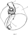
FIG. 7 is a partial structural schematic diagram of an integrated washer dryer according to an embodiment. - In the drawings:
1. condenser body; 11. cavity; 12. water inlet; 13. hot and humid air inlet; 14. dry air outlet; 2. boss; 21. boss hole; 22. first guide surface; 23. second guide surface; 3, drying fan; 4, heating device; 5. drum. - The present disclosure is described hereinafter through specific embodiments in conjunction with the accompanying drawings.
- As shown in
FIGS. 1 to 6 , the present embodiment provides a water-cooled condenser, which may be applied to an integrated washer dryer for condensing hot and humid air to achieve drying effect. - The water-cooled condenser includes a condenser body 1, the condenser body 1 has a hollow interior to form a
cavity 11, the condenser body 1 is provided with a hot andhumid air inlet 13, adry air outlet 14, and a condensate water inlet that are respectively in communication with thecavity 11. After the hot and humid air enters thecavity 11 from the hot andhumid air inlet 13 and exchanges heat with the condensate water that enters thecavity 11 through the condensate water inlet, the hot and humid air is condensed into liquid after giving out heat, and is discharged out of thecavity 11 together with the condensate water; at the same time, the hot and humid air turns into dry air and is discharged from thedry air outlet 14 to complete a heat exchange process. - In a condensation process of the hot and humid air, debris such as threads or hair might enter the
cavity 11 together with the hot and humid air and attach to an inner wall of thecavity 11. In order to avoid accumulation of the debris, such as threads, and increase air resistance of warm air to affect the drying effect, the water-cooled condenser in the present embodiment further includes aboss 2 and awater inlet 12, where thewater inlet 12 is the condensate water inlet. In an embodiment, flushing water may be introduced through thewater inlet 12, and thewater inlet 12 is located at an upper end of the condenser body 1, so that the flushing water may flush the inner wall of thecavity 11 from top to bottom. Theboss 2 is disposed on the inner wall ofcavity 11, and thewater inlet 12 is in communication with thecavity 11 and is used to introduce the flushing water to flush the inner wall of thecavity 11, so that the water-cooled condenser has a function of cleaning debris such as threads. - As shown in
FIG. 5 , when the flushing water enters thecavity 11 from thewater inlet 12, and due to a large flow of the flushing water, the flushing water collides with theboss 2, so that the flushing water is scattered by theboss 2 and splashed around and upward to flush the inner wall of the condenser body 1, and then the threads or hairs attached to the inner wall are flushed away and discharged out of the condenser body 1 together with the flushing water. In order to improve the flushing effect of the flushing water, the flushing water may have a certain pressure, which is conducive to the upward splashing of the flushing water, thereby increasing a flushing area and a flushing force. - As shown in
FIG. 3 , in order to increase the flushing area and improve the flushing effect on the inner wall of water scattered by theboss 2, theboss 2 may be disposed on the inner wall of the cavity and adjacent to thewater inlet 12, so that the water scattered by theboss 2 flush the inner wall of thecavity 11 from the top of thecavity 11, where the flushing area is large and the flushing effect is good. - In an embodiment, in order to collide all the flushing water with the
boss 2 after the flushing water enters thecavity 11 so as to splash the water around and upward, theboss 2 may be long-strip shaped and perpendicular to a flow direction of the flushing water, such that a blocking effect is applied to the flushing water and the flushing water collides with the boss and is scattered. - As shown in
FIG. 4 , in order to splash the flushing water upward when colliding with theboss 2 so as to increase the flushing area of the flushing water, an end portion of theboss 2 is bent upward and forms a groove with the inner wall of thecavity 11, and the end portion of theboss 2 is inclined, from top to bottom, away from a center of the cavity, that is, the end portion of theboss 2 expands outward, so as to provide a certain guiding effect for the flushing water, so that the flushing water is splashed upward along the end portion of theboss 2, to flush the inner wall of thecavity 11. The inner wall of the groove includes afirst guide surface 22 and asecond guide surface 23, thefirst guide surface 22 is connected to the inner wall of the cavity, thesecond guide surface 23 is connected to thefirst guide surface 22, and thefirst guide surface 22 is a flat surface and thesecond guide surface 23 is an inclined surface, so that the end portion of theboss 2 is expanded outward. Thefirst guide surface 22 may also be a curved surface that is recessed inward, as long as a certain guiding effect for the flushing water is provided to splash the flushing water upward. - In addition, the
boss 2 may be transited to the inner wall of thecavity 11 on a side adjacent to thewater inlet 12 via an inclined surface or a curved surface, each of which plays a guiding effect on the flushing water, thereby splashing the flushing water upward and increasing the splash area. - The condensate water needs to be introduced in a working process of the water-cooled condenser. To simplify a structure of the condenser body 1, the condensate water inlet and the
water inlet 12 may be a same inlet. When condensation is needed, the condensate water is introduced via the inlet; and when the inner wall of thecavity 11 needs to be flushed, flushing water is introduced via the inlet. - In an embodiment, when the condensate water is introduced, in order to prevent the condensate water from being splashed upward by the guiding effect of the
boss 2 to affect the condensation effect, as shown inFIG. 2 , theboss 2 is further provided with aboss hole 21. Due to a small flow of the condensate water, after introduced via thewater inlet 12, the condensate water will directly flow out through theboss hole 21 to avoid being guided by theboss 2. As shown inFIG. 6 , theboss hole 21 may be adjacent to a connection between theboss 2 and thecavity 11, so that after introduced from thewater inlet 12, the condensate water naturally enters theboss hole 21 along the inner wall of thecavity 11. At the same time, in order to avoid changes of a flow path of the condensate water to affect the condensation effect, theboss hole 21 may also be in communication with the flow path of the condensate water, so that the condensate water continues to flow according to the flow path of the condensate water to achieve a better condensation purpose. - When the flushing water is introduced, due to the large flow of the flushing water, the flushing water cannot pass through the
boss hole 21, so that the flushing water may only flow along theboss 2 and splash upward while colliding with theboss 2, thereby increasing the flushing area of the scattered water. - In the present embodiment, the
boss 2 may be integrally formed with a side wall of the condenser body 1, for example, theboss 2 may be a convex structure formed by recessing the side wall of the condenser body 1 inward thecavity 11, or a convex structure convexly arranged on the inner wall of thecavity 11. Theboss 2 being integrally formed with the condenser body 1 may improve the impact resistance of theboss 2. Theboss 2 may be a separate structure, which may be fixed to the inner wall of thecavity 11 by a fastening device, as long as the effect of scattering and splashing the flushing water may be achieved. - As shown in
FIG.7 , the present embodiment further provides an integrated washer dryer, including a drum 5, a drying device, and the above-mentioned water-cooled condenser, where an air outlet of the drying device is in communication with the drum 5, a hot andhumid air inlet 13 of the water-cooled condenser is in communication with the drum 5, and adry air outlet 14 of the water-cooled condenser is in communication with the drying device. The drying device includes a drying fan 3 and a heating device 4, where the air is heated by the heating device 4 and then enters the drum 5 through the air outlet to heat the clothes; the hot and humid air with moisture enters the water-cooled condenser through the hot andhumid air inlet 13 of the water-cooled condenser, that is, to enter thecavity 11, the hot and humid air is condensed into liquid by the water-cooled condenser and flows out with the condensate water; and the dried dry air is introduced into the heating device 4 by the drying air and enters a next cycle. - The water-cooled condenser in the integrated washer dryer provided in the present embodiment has the function of cleaning debris such as threads. By providing the
boss 2, the flushing water entering the interior of the condenser body 1 is scattered, and the scattered water is splashed toward multiple directions under the guiding effect of theboss 2, thereby flushing the inner wall of the condenser body 1 with a large flushing area, and flushing away debris such as threads attached to the inner wall of the condenser body 1, so that the circulating air volume inside the condenser body 1 is ensured and the air resistance is reduced, thereby improving the drying effect of the integrated washer dryer and reducing the failure rate of the integrated washer dryer. When the condensate water is introduced, due to a small flow of the condensate water, the condensate water will flow out through the boss hole, so as to avoid changing the flow path of the condensate water to affect the condensation effect after the condensate water is splashed along the boss.
Claims (9)
- A water-cooled condenser, comprising:a condenser body (1), wherein the condenser body (1) has a hollow interior to form a cavity (11), an upper end of the condenser body (1) is provided with a water inlet (12) that is in communication with the cavity (11); anda boss (2) disposed on an inner wall of the cavity (11) and provided with a boss hole (21);wherein the boss is configured to, in response to flushing water being introduced into the water inlet (12), splash the flushing water around after the flushing water collides with the boss, so as to flush the inner wall of the condenser body (1); andthe boss is further configured to, in response to condensate water being introduced into the water inlet (12), flow the condensate water out from the boss hole (21).
- The water-cooled condenser according to claim 1, wherein the boss (2) is disposed on the inner wall of the cavity (11) and adjacent to the water inlet (12).
- The water-cooled condenser according to claim 2, wherein the boss (2) is integrally formed with a side wall of the condenser body (1).
- The water-cooled condenser according to claim 3, wherein the boss (2) is formed by recessing the side wall of the condenser body (1) inward the cavity (11).
- The water-cooled condenser according to any one of claims 1-4, wherein the boss (2) is long-strip shaped and is perpendicular to a flow direction of waterflow.
- The water-cooled condenser according to any one of claims 1-4, wherein an end portion of the boss (2) is bent upward and forms a groove with the inner wall of the cavity (11), and the end portion of the boss (2) is inclined from top to bottom away from a center of the cavity (11).
- The water-cooled condenser according to claim 6, wherein an inner wall of the groove comprises a first guide surface (22) and a second guide surface (23), the first guide surface (22) is connected to the inner wall of the cavity (11) and is a flat surface or a concave arc surface, and the second guide surface (23) is connected to the first guide surface (22) and is an inclined surface.
- The water-cooled condenser according to any one of claims 1-4, wherein the boss hole (21) is adjacent to a connection between the boss (2) and the cavity (11), and is in communication with a flow path of the condensate water.
- An integrated washer dryer, comprising:a drum (5);a drying device, an air outlet of which is in communication with the drum (5); anda water-cooled condenser according to any one of claims 1-8, wherein a hot and humid air inlet of the water-cooled condenser is in communication with the drum (5), and a dry air outlet of the water-cooled condenser is in communication with an air inlet of the drying device.
Applications Claiming Priority (2)
| Application Number | Priority Date | Filing Date | Title |
|---|---|---|---|
| CN201710847510.6A CN109518440B (en) | 2017-09-19 | 2017-09-19 | Water-cooled condenser and washing and drying integrated machine |
| PCT/CN2018/105994 WO2019057008A1 (en) | 2017-09-19 | 2018-09-17 | Water-cooled condenser and integrated washer dryer |
Publications (2)
| Publication Number | Publication Date |
|---|---|
| EP3686337A1 true EP3686337A1 (en) | 2020-07-29 |
| EP3686337A4 EP3686337A4 (en) | 2021-06-23 |
Family
ID=65768386
Family Applications (1)
| Application Number | Title | Priority Date | Filing Date |
|---|---|---|---|
| EP18858674.7A Withdrawn EP3686337A4 (en) | 2017-09-19 | 2018-09-17 | WATER-COOLED CONDENSER AND INTEGRATED WASH-DRYER |
Country Status (3)
| Country | Link |
|---|---|
| EP (1) | EP3686337A4 (en) |
| CN (1) | CN109518440B (en) |
| WO (1) | WO2019057008A1 (en) |
Families Citing this family (5)
| Publication number | Priority date | Publication date | Assignee | Title |
|---|---|---|---|---|
| CN110804850B (en) * | 2018-07-19 | 2022-04-26 | 重庆海尔滚筒洗衣机有限公司 | Condenser for washing and drying integrated machine and control method of washing and drying integrated machine |
| CN113445281B (en) * | 2020-03-25 | 2025-08-19 | 青岛海尔智能技术研发有限公司 | Lint removal module and washing and drying machine |
| CN113668206B (en) * | 2020-05-13 | 2025-04-25 | 青岛海尔智能技术研发有限公司 | Washing machine and dryer |
| CN115821554B (en) * | 2021-09-17 | 2025-11-25 | 青岛海尔洗涤电器有限公司 | Drying equipment |
| CN116122030A (en) * | 2021-11-15 | 2023-05-16 | 合肥海尔滚筒洗衣机有限公司 | Washing and drying integrated machine condenser structure and washing and drying integrated machine |
Family Cites Families (13)
| Publication number | Priority date | Publication date | Assignee | Title |
|---|---|---|---|---|
| US2843943A (en) * | 1953-11-02 | 1958-07-22 | Whirlpool Co | Combined washer and drier |
| GB8507722D0 (en) * | 1985-03-25 | 1985-05-01 | Hotpoint Ltd | Washing machines |
| DE19511344C2 (en) * | 1995-03-28 | 2003-04-17 | Miele & Cie | Program-controlled washer dryer |
| KR100629333B1 (en) * | 2004-04-09 | 2006-09-29 | 엘지전자 주식회사 | Washing device heating method and washing method |
| KR100631574B1 (en) * | 2005-08-13 | 2006-10-09 | 엘지전자 주식회사 | Condensation Laundry Dryer |
| CN101387059B (en) * | 2007-09-11 | 2010-11-03 | 博西华电器(江苏)有限公司 | Control method of laundry washing equipment with drying program |
| CN102517860B (en) * | 2011-12-19 | 2016-08-31 | 青岛海尔滚筒洗衣机有限公司 | Drying system and the thread waste clearing method for same of drying system |
| CN103572569B (en) * | 2012-07-27 | 2017-02-15 | 博西华电器(江苏)有限公司 | Household appliance with water supply component |
| CN203569351U (en) * | 2013-07-05 | 2014-04-30 | 海尔集团公司 | Integrated washing-drying machine |
| CN204690433U (en) * | 2015-04-15 | 2015-10-07 | 无锡小天鹅股份有限公司 | For washing machine condenser and there is its roller washing machine |
| CN105544166B (en) * | 2016-02-03 | 2018-03-30 | 海信(山东)冰箱有限公司 | A kind of water condensing unit and washing-drying integral machine |
| CN205688218U (en) * | 2016-06-12 | 2016-11-16 | 海信(山东)冰箱有限公司 | A kind of condenser and washing-drying integral machine |
| CN206189149U (en) * | 2016-09-30 | 2017-05-24 | 无锡小天鹅股份有限公司 | A all -in -one washer dryer that is used for all -in -one washer dryer's condenser assembly and has it |
-
2017
- 2017-09-19 CN CN201710847510.6A patent/CN109518440B/en active Active
-
2018
- 2018-09-17 WO PCT/CN2018/105994 patent/WO2019057008A1/en not_active Ceased
- 2018-09-17 EP EP18858674.7A patent/EP3686337A4/en not_active Withdrawn
Also Published As
| Publication number | Publication date |
|---|---|
| WO2019057008A1 (en) | 2019-03-28 |
| EP3686337A4 (en) | 2021-06-23 |
| CN109518440A (en) | 2019-03-26 |
| CN109518440B (en) | 2022-04-19 |
Similar Documents
| Publication | Publication Date | Title |
|---|---|---|
| CN109554901B (en) | A drying washing machine | |
| WO2020088331A1 (en) | Washing machine | |
| EP2169107B1 (en) | Drying appliance comprising a spraying device | |
| CN105544166B (en) | A kind of water condensing unit and washing-drying integral machine | |
| CN207452524U (en) | A drum washing and drying machine | |
| WO2019057008A1 (en) | Water-cooled condenser and integrated washer dryer | |
| JP2014046133A (en) | Clothes dryer | |
| JP5982342B2 (en) | Drum washing machine | |
| KR100617110B1 (en) | Drying Drum Washing Machine | |
| CN109518441A (en) | A kind of water cooled condenser and washing-drying integral machine | |
| KR20060055576A (en) | washer | |
| CN103882663B (en) | A kind of dryer collecting box structure and dryer | |
| EP1621662A2 (en) | Washing machine | |
| KR101141641B1 (en) | structure for condensing duct of drum type washing machine with laundry drying function | |
| JP7466004B2 (en) | Condensers for drying equipment and drying equipment | |
| KR100556420B1 (en) | Drying Drum Washing Machine | |
| KR20110033410A (en) | Condensation Dryer | |
| KR100662567B1 (en) | washer | |
| KR100781245B1 (en) | Drying Type Switching Dryer of Drum Washing Machine | |
| CN109295653B (en) | Washing and drying integrated machine and condenser thereof | |
| CN223240416U (en) | Base device and clothes treatment equipment | |
| KR20050101738A (en) | Drum-type washing machine with dryer | |
| KR20070075484A (en) | Water-cooled condensers in laundry processing equipment | |
| CN111021013B (en) | Base and clothes treatment device | |
| CN113668205B (en) | Condensation thread-removing mechanism and washing and drying machine |
Legal Events
| Date | Code | Title | Description |
|---|---|---|---|
| STAA | Information on the status of an ep patent application or granted ep patent |
Free format text: STATUS: THE INTERNATIONAL PUBLICATION HAS BEEN MADE |
|
| PUAI | Public reference made under article 153(3) epc to a published international application that has entered the european phase |
Free format text: ORIGINAL CODE: 0009012 |
|
| STAA | Information on the status of an ep patent application or granted ep patent |
Free format text: STATUS: REQUEST FOR EXAMINATION WAS MADE |
|
| 17P | Request for examination filed |
Effective date: 20200420 |
|
| AK | Designated contracting states |
Kind code of ref document: A1 Designated state(s): AL AT BE BG CH CY CZ DE DK EE ES FI FR GB GR HR HU IE IS IT LI LT LU LV MC MK MT NL NO PL PT RO RS SE SI SK SM TR |
|
| AX | Request for extension of the european patent |
Extension state: BA ME |
|
| DAV | Request for validation of the european patent (deleted) | ||
| DAX | Request for extension of the european patent (deleted) | ||
| A4 | Supplementary search report drawn up and despatched |
Effective date: 20210521 |
|
| RIC1 | Information provided on ipc code assigned before grant |
Ipc: D06F 58/24 20060101AFI20210517BHEP Ipc: D06F 25/00 20060101ALI20210517BHEP |
|
| STAA | Information on the status of an ep patent application or granted ep patent |
Free format text: STATUS: EXAMINATION IS IN PROGRESS |
|
| 17Q | First examination report despatched |
Effective date: 20230504 |
|
| STAA | Information on the status of an ep patent application or granted ep patent |
Free format text: STATUS: THE APPLICATION IS DEEMED TO BE WITHDRAWN |
|
| 18D | Application deemed to be withdrawn |
Effective date: 20250301 |