EP3686148B1 - A safety apparatus for an escalator and an escalator comprising the safety apparatus - Google Patents
A safety apparatus for an escalator and an escalator comprising the safety apparatus Download PDFInfo
- Publication number
- EP3686148B1 EP3686148B1 EP20153378.3A EP20153378A EP3686148B1 EP 3686148 B1 EP3686148 B1 EP 3686148B1 EP 20153378 A EP20153378 A EP 20153378A EP 3686148 B1 EP3686148 B1 EP 3686148B1
- Authority
- EP
- European Patent Office
- Prior art keywords
- escalator
- skirt
- profile
- safety apparatus
- section
- Prior art date
- Legal status (The legal status is an assumption and is not a legal conclusion. Google has not performed a legal analysis and makes no representation as to the accuracy of the status listed.)
- Active
Links
Images



Classifications
-
- B—PERFORMING OPERATIONS; TRANSPORTING
- B66—HOISTING; LIFTING; HAULING
- B66B—ELEVATORS; ESCALATORS OR MOVING WALKWAYS
- B66B29/00—Safety devices of escalators or moving walkways
- B66B29/005—Applications of security monitors
-
- B—PERFORMING OPERATIONS; TRANSPORTING
- B66—HOISTING; LIFTING; HAULING
- B66B—ELEVATORS; ESCALATORS OR MOVING WALKWAYS
- B66B21/00—Kinds or types of escalators or moving walkways
- B66B21/02—Escalators
- B66B21/04—Escalators linear type
-
- B—PERFORMING OPERATIONS; TRANSPORTING
- B66—HOISTING; LIFTING; HAULING
- B66B—ELEVATORS; ESCALATORS OR MOVING WALKWAYS
- B66B23/00—Component parts of escalators or moving walkways
- B66B23/22—Balustrades
- B66B23/225—Lighting systems therefor
-
- B—PERFORMING OPERATIONS; TRANSPORTING
- B66—HOISTING; LIFTING; HAULING
- B66B—ELEVATORS; ESCALATORS OR MOVING WALKWAYS
- B66B25/00—Control of escalators or moving walkways
- B66B25/006—Monitoring for maintenance or repair
-
- B—PERFORMING OPERATIONS; TRANSPORTING
- B66—HOISTING; LIFTING; HAULING
- B66B—ELEVATORS; ESCALATORS OR MOVING WALKWAYS
- B66B29/00—Safety devices of escalators or moving walkways
- B66B29/02—Safety devices of escalators or moving walkways responsive to, or preventing, jamming by foreign objects
Definitions
- the present disclosure relates to an escalator skirt safety apparatus for an escalator and an escalator comprising such escalator skirt safety apparatus.
- the skirt of the escalator is located on both sides of the escalator, and mainly plays a role of safety and beauty. Due to the special nature of the working structure, there must be a gap of different size between the skirt and the steps, and the gap is likely to cause accidents, such as the passengers' shoes, pants, and even the fingers of children being clamped. Therefore, a skirt brush, that is, a skirt anti-pinch device, is usually installed on the skirt of the escalator, which can prevent foreign objects from entering the gap between the skirt and the steps; or an illumination device is installed on the skirt of the escalator, which can alert passengers to stay away from the gap. In addition, for example, during the maintenance of the escalator, the operator sets the escalator to a disabled state. Considering safety factors, it is necessary to ensure that the escalator remains in a disabled state when someone or an object enters the escalator. Generally, sensors are installed on the skirt to detect whether people or objects enter the escalator.
- the escalator generally comprises an upper horizontal section, a lower horizontal section, and an inclined section, and at the curved section between the horizontal section and the inclined section, the skirt of the escalator is bent. Due to the limitation of the manufacturing materials and processing technology of the skirt, the height of the skirt in the height direction of the escalator should not be too large, otherwise the mechanical strength of the skirt is not enough, so it is prone to problems such as fracture and it even makes it is impossible to form. Therefore, the space for installing additional devices on the skirt is limited. In addition, installing additional devices on the skirt requires processing a profile with a mounting groove, and placing additional devices along the curved section of the skirt usually requires a curved profile.
- the height of the profile in the height direction of the escalator should not be too large, otherwise the profile with the mounting groove will be deformed at the curved section. This further increases the difficulty of installing additional devices on the skirt.
- a skirt brush is installed on the skirt, or only sensors are installed on the skirt, or both the skirt brush and the light strip are installed on the skirt, or both the skirt brush and the sensors are installed on the skirt. There is no technology to install the skirt brush, the illumination device and the sensors on the skirt.
- US20160368741A1 discloses a safety apparatus according to the preamble of claim 1. It discloses an escalator or a moving walkway, the escalator or the moving walkway has two access regions, each with a comb plate, and a conveying region arranged between the access regions. The conveying region extends between the two comb plates of the access regions. At least one projection projects into the conveying region at at least one stationary part of the escalator or moving walkway. At least one monitoring sensor is arranged at least partly in the at least one projection.
- the document CN206915553U discloses an anti-pinch structure of automatic gangway which belongs to gangway technical field.
- the structure includes a skirt, a skirt brush holder provided on the skirt, a skirt brush provided on the skirt brush holder, and a photoelectric sensor device provided on the skirt brush holder.
- the photoelectric sensor device is located in the middle section of the whole skirt, the photoelectric sensor unit device is located below the skirt brush.
- the skirt brush is used to prevent shoes, trouser legs and skirts from being involved in the gap between the skirt and causing foot extrusion and other accidents.
- the photoelectric sensor device is installed in the middle section of the whole skirt.
- the document CN106494986A discloses a skirt board anti-pinch device and an escalator.
- the skirt board anti-pinch device comprises a skirt board, an anti-pinch mechanism and a lighting assembly.
- the anti-pinch mechanism is arranged on the skirt board and comprises a fixing base.
- the fixing base is provided with a connecting plate and an anti-kicking part.
- a safety containing cavity is formed between the anti-kicking part and an escalator stair.
- the lighting assembly comprises a lampshade. The lampshade and the connecting plate are connected in a clamped manner, and the lampshade is pressed on the fixing base.
- the safety containing cavity is formed between the anti-kicking part and the escalator stair, and therefore it is guaranteed that the emergent rays of the lighting assembly cannot be shielded, and a good lighting effect is guaranteed. Meanwhile, the problem that due to the dark rays and other factors, passenger feet kick and pedal the lighting assembly, and consequently a lamp is damaged can be solved through the safety containing cavity, safety usage and the service life of the lighting assembly and the skirt board anti-pinch device are ensured, and the subsequent maintaining and replacing cost is reduced.
- the document US20160185573A1 discloses a lighting system for attachment to a human conveyor, such as to an escalator or moving sidewalk.
- the system comprises an elongate body having two or more grooves extending longitudinally along a substantial length of the elongate body, wherein the grooves contain an elongate rope light and an elongate brush, respectively.
- the rope light can be placed in the upper groove or in the lower groove. Alternatively, rope lights can be placed in both grooves and the brush eliminated.
- the document WO2008080423A1 discloses a people conveyor (2) having a people transportation band (4), a stationary lateral structure (14) laterally adjacent to the transportation band (4), and a brush guard (16) attached to the lateral structure (14) and extending along the transportation band (4) and over a lateral margin (18) of the transportation band (4), and further comprising a brush guard illumination means (34) extending together with the brush guard (16).
- an object of the present disclosure is to provide an escalator skirt safety apparatus for an escalator and an escalator comprising such escalator skirt safety apparatus.
- a skirt brush, an illumination device and sensors are integrated into the escalator skirt safety apparatus, and the escalator skirt safety apparatus has a small volume, a simple structure and a low cost, and is safe and beautiful.
- the present disclosure relates to an escalator skirt safety apparatus for an escalator, the escalator skirt safety apparatus is disposed on a skirt of the escalator along a length of the skirt, and the escalator skirt safety apparatus comprises a one-piece profile which comprises, along a length of the profile, a rear wall, an upper portion at an upper end of the rear wall and extending toward a step side, and a lower portion at a lower end of the rear wall and extending toward the step side, wherein a plurality of sensor holes are provided on the rear wall; and the escalator skirt safety apparatus further comprises an illumination device, a skirt brush, and a plurality of photoelectric sensors, wherein the illumination device is disposed on the profile and emits illumination light toward the step side, wherein the skirt brush is disposed on the lower portion of the profile along the length of the profile, wherein the plurality of photoelectric sensors are mounted to be respectively aligned with the plurality of sensor holes on the rear wall so as to emit and/or receive optical signals through the pluralit
- the profile comprises an upper horizontal section, an inclined section, a lower horizontal section, an upper curved section disposed between the upper horizontal section and the inclined section, and a lower curved section disposed between the inclined section and the lower horizontal section.
- a plurality of mounting holes are provided on a rear wall of the upper curved section and a rear wall of the lower curved section, and the escalator skirt safety apparatus is mounted on the skirt at the upper curved section and the lower curved section by providing screws in the plurality of mounting holes.
- a closed upper cavity is formed by the upper portions and the rear walls of the upper curved section and the lower curved section
- a closed lower cavity is formed by the lower portions and the rear walls of the upper curved section and the lower curved section.
- an open upper mounting cavity is formed by the upper portions and the rear walls of the upper horizontal section, the inclined section and the lower horizontal section, and an open lower mounting cavity is formed by the lower portions and the rear walls of the upper horizontal section, the inclined section and the lower horizontal section.
- the escalator skirt safety apparatus is mounted on the skirt by providing sunk screws in the open upper mounting cavity and lower mounting cavity at the upper horizontal section, the lower horizontal section and the inclined section.
- the escalator skirt safety apparatus further comprises a light-transmissive cover, wherein the light-transmissive cover is disposed at ends on the step side of the upper portion and the lower portion along the length of the profile.
- the upper portion comprises an upper protrusion at the end thereof on the step side
- the lower portion comprises a lower protrusion at the end thereof on the step side, wherein the light-transmissive cover is snapped onto the profile by the upper protrusion and the lower protrusion.
- the upper portion of the profile is provided with a first groove, and the illumination device is disposed in the first groove.
- the first groove is inclined such that the illumination device emits illumination light obliquely toward the step side.
- the lower portion of the profile is provided with a first groove, and the illumination device is disposed in the first groove.
- the lower portion of the profile is provided with a second groove, and the skirt brush is disposed in the second groove.
- the plurality of sensor holes are uniformly distributed along the length of the profile.
- the illumination device is an LED light strip that extends along the length of the profile.
- the illumination device is a plurality of LED lamps uniformly distributed along the length of the profile.
- the present disclosure also relates to an escalator comprising steps and two skirts on two sides of the steps, which is characterized in that, the escalator further comprises the escalator skirt safety apparatus as described above, wherein the escalator skirt safety apparatus is disposed on at least one of the skirts.
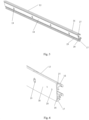
- Fig. 1 shows a one-piece profile 1 of a safety apparatus for an escalator of the present disclosure.
- the safety device is disposed on the skirt of the escalator along the length of the skirt.
- the movement direction of the escalator is basically the left-to-right direction x in the figure
- the height direction of the escalator is the bottom-to-top direction y
- the width direction of the escalator is the direction z perpendicular to the movement direction and the height direction.
- Steps (not shown) of the escalator are arranged between two skirts of the escalator along the width direction z.
- the one-piece profile 1 in Fig. 1 is disposed along the length of the skirt, and in the movement direction x of the escalator, the profile 1 comprises an upper horizontal section 11, an inclined section 12, a lower horizontal section 13, an upper curved section 14 disposed between the upper horizontal section and the inclined, and a lower curved section 15 disposed between the inclined section and the lower horizontal section.
- the profile 1 of the safety apparatus may comprise only the upper horizontal section 11, the inclined section 12 and the lower horizontal section 13.
- Fig. 2 shows a partial schematic view of the profile of the safety apparatus of the present disclosure.
- the bottom-to-top direction y in Fig. 2 is the height direction of the escalator
- the direction x is the movement direction of the escalator
- the direction z is the width direction of the escalator.
- the steps of the escalator are provided along the width direction z.
- the profile 1 comprises a rear wall 18, an upper portion 16 at the upper end of the rear wall and extending toward the step side, and a lower portion 17 at the lower end of the rear wall and extending toward the step side.
- a plurality of sensor holes 19 are provided on the rear wall 18 along the length of the profile 1.
- the rear wall 18 of the lower curved section of the profile 1 comprises a plurality of mounting holes 20.
- the rear wall of the upper curved section also comprises a plurality of mounting holes.
- the safety apparatus is mounted on the skirt along the length of the skirt by screws passing through the plurality of mounting holes 20 and corresponding holes on the skirt.
- the plurality of sensor holes 19 are uniformly distributed along the length of the profile.
- the sensor holes of the present disclosure may also be unevenly distributed on the rear wall of the profile.
- Fig. 3 shows a sectional view of one embodiment of the safety apparatus 100.
- the right-to-left direction z shown in Fig. 3 is the width direction of the escalator, and the bottom-to-top direction y is the height direction of the escalator.
- the steps of the escalator are provided along the width direction z.
- the safety apparatus 100 further comprises a light-transmissive cover 2, an illumination device 3, a skirt brush 4, and a plurality of photoelectric sensors 5.
- the light-transmissive cover 2 may be, for example, a transparent or translucent cover.
- the safety apparatus may not comprise the light-transmissive cover, or the illumination device itself may comprise a light-transmissive cover.
- the light-transmissive cover 2 is disposed at the ends on the step side of the upper portion 16 and the lower portion 17 along the length of the profile 1.
- the illumination device 3 is arranged on the upper portion 16 of the profile 1 and emits illumination light towards the step side.
- the illumination device may also be arranged in other parts of the profile.
- the skirt brush 4 is arranged on the lower portion 17 of the profile along the length of the profile 1.
- each photoelectric sensor 5 is aligned with each sensor hole 19 on the rear wall 18 to emit and/or receive optical signals through each sensor hole.
- the photoelectric sensor 5 can be mounted on the rear wall 18 of the profile 1.
- the plurality of sensor holes 19 are uniformly distributed along the length of the profile, so that the plurality of photoelectric sensors 5 can be uniformly distributed along the length of the profile, but the present disclosure is not limited thereto, and the sensor distribution may be non-uniform.
- the photoelectric sensors 5 ensure that the escalator is always in a disabled state, which will not cause accidental injury to people and improve the safety of the escalator.
- Fig. 4 is a sectional view of one embodiment of the safety apparatus 100 of the present disclosure.
- the upper portion 16 comprises an upper protrusion 21 at its end on the step side (i.e., at its end remote from the skirt 200), and the lower portion comprises a lower protrusion 22 at its end on the step side (i.e., at its end remote from the skirt 200), wherein the light-transmissive cover 2 is snapped onto the profile 1 by means of the upper protrusion 21 and the lower protrusion 22.
- the light-transmissive cover can also be mounted on the profile by screws or bonded to the profile, and the installation manner of the light-transmissive cover of the present disclosure is not limited to the above embodiments.
- the profile 1 shown in Fig. 4 is mounted on one side of the skirt 200, the photoelectric sensor 5 is aligned with the sensor hole 19 on the rear wall 18 and the corresponding hole on the skirt 200, and is mounted on the other side of the skirt by a bracket fixed to the skirt 200.
- the upper portion 16 of the profile may be provided with a first groove 23, and the illumination device 3 is disposed in the first groove 23.
- the first groove 23 may be set to be parallel to the skirt 200.
- the first groove 23 may also be provided in the lower portion 17 of the profile.
- the first groove 23 is inclined with respect to the width direction z of the escalator, so that the illumination device 3 is disposed obliquely in the profile 1 and emits the illumination light toward the step side. In this way, the safety apparatus can be compact and occupy a smaller volume.
- the illumination device 3 shown in Figs. 3 and 4 is an LED light strip extending along the length of the profile 1.
- the illumination device may be a plurality of LED lamps, which are uniformly distributed along the length of the profile.
- the lower portion 17 of the profile may be provided with a second groove 24 in which the skirt brush 4 is arranged.
- the profile 1 comprises two second grooves 24. According to actual needs, the profile may comprise only one second groove 24.
- the number of skirt brushes in the safety apparatus of the present disclosure is not limited to the embodiments described herein.
- the skirt device, the illumination device and the sensors are integrated in the safety apparatus of the present disclosure, so the volume is small, the structure is simple, the cost is low, and the apparatus is safe and beautiful.
- Fig. 2 shows the lower curved section, a part of the lower horizontal section and a part of the inclined section of the profile
- Fig. 5 shows an enlarged schematic view of a part of the inclined section of the profile shown in Fig. 2
- Fig. 6 shows an enlarged schematic view of a part of the lower curved section of the profile shown in Fig. 2
- Fig. 7 shows an enlarged schematic view of a part of the lower horizontal section of the profile shown in Fig. 2 .
- the rear wall 18 together with the upper portion 16 and the lower portion 17 of the lower curved section 15 in Fig. 6 form a closed upper cavity 25 and a closed lower cavity 26, respectively.
- the upper curved section 14 also has a closed upper cavity 25 and a closed lower cavity 26 formed by the rear wall 18 together with the upper portion 16 and the lower portion 17, respectively.
- the rear wall 18 and the upper section 16 of the inclined section 12 and the lower horizontal section 13 form an open upper mounting cavity 27, and the rear wall 18 and the lower section 17 of the inclined section 12 and the lower horizontal section 13 form an open lower mounting cavity 28.
- the safety apparatus is mounted on the skirt by providing screws in a plurality of mounting holes 20.
- the safety apparatus is mounted on the skirt 200 by providing sunk screws in the open upper mounting cavity 27 and the open lower mounting cavity 28, as shown in the sectional views of Figs. 3 and 4 .
- the rear wall 18 of the upper horizontal section, the lower horizontal section and the inclined section may not comprise mounting holes.
- the present disclosure can freely set the position of the sunk screws through the open mounting cavity formed along the length of the profile, and it is not necessary to manufacture precisely aligned mounting holes in the profile and the skirt, thereby improving the installation freedom of the safety apparatus and reducing processing accuracy requirements for safety apparatus and skirts.
- the upper horizontal section, the lower horizontal section and the inclined section of the profile 1 may further comprise a process cavity 29 located below the lower mounting cavity 28.
- the upper horizontal section, the lower horizontal section, and the inclined section of the profile may also comprise a closed upper cavity and a closed lower cavity, and the profile is mounted on the skirt through mounting holes with screws.
- Fig. 8 shows a schematic diagram of one embodiment of an escalator 300 according to the present disclosure.
- the escalator 300 includes steps (not shown in Fig. 8 ) and two skirts 200 located on both sides of the steps.
- the safety apparatus 100 of the present disclosure is disposed on two skirts 200 of the escalator 300 shown in Fig. 8 . According to the actual situation, the safety apparatus 100 of the present disclosure may be disposed on only one skirt 200 of the escalator 300.
- the photoelectric sensor 5 may be an active infrared sensor, which comprises a transmitting system and a receiving system, wherein the transmitting system emits an infrared beam in the width direction of the escalator, and the infrared beam is received by the receiving system located on the skirt on the other side of the escalator. Therefore an infrared beam warning line is formed.
- the infrared beam is blocked, and the sensor detects that a person or an object enters the escalator, thereby keeping the escalator in a disabled state.
- the safety apparatuses comprising such an active infrared sensor are provided on two skirts of the escalator.
- the photoelectric sensor 5 may be, for example, a passive infrared sensor that senses infrared radiation of a human body.
- the infrared sensor detects the infrared radiation of the human body, and then the escalator is kept in the disabled state.
- the safety apparatus comprising such a passive infrared sensor may be provided on only one skirt of the escalator, or on two skirts of the escalator.
- the photoelectric sensor of the present disclosure is not limited to the above two cases, and the photoelectric sensor of the present disclosure may also be a sensor that emits visible light.
Landscapes
- Escalators And Moving Walkways (AREA)
Description
- The present disclosure relates to an escalator skirt safety apparatus for an escalator and an escalator comprising such escalator skirt safety apparatus.
- The skirt of the escalator is located on both sides of the escalator, and mainly plays a role of safety and beauty. Due to the special nature of the working structure, there must be a gap of different size between the skirt and the steps, and the gap is likely to cause accidents, such as the passengers' shoes, pants, and even the fingers of children being clamped. Therefore, a skirt brush, that is, a skirt anti-pinch device, is usually installed on the skirt of the escalator, which can prevent foreign objects from entering the gap between the skirt and the steps; or an illumination device is installed on the skirt of the escalator, which can alert passengers to stay away from the gap. In addition, for example, during the maintenance of the escalator, the operator sets the escalator to a disabled state. Considering safety factors, it is necessary to ensure that the escalator remains in a disabled state when someone or an object enters the escalator. Generally, sensors are installed on the skirt to detect whether people or objects enter the escalator.
- The escalator generally comprises an upper horizontal section, a lower horizontal section, and an inclined section, and at the curved section between the horizontal section and the inclined section, the skirt of the escalator is bent. Due to the limitation of the manufacturing materials and processing technology of the skirt, the height of the skirt in the height direction of the escalator should not be too large, otherwise the mechanical strength of the skirt is not enough, so it is prone to problems such as fracture and it even makes it is impossible to form. Therefore, the space for installing additional devices on the skirt is limited. In addition, installing additional devices on the skirt requires processing a profile with a mounting groove, and placing additional devices along the curved section of the skirt usually requires a curved profile. Due to the limitation of the material of the profile and the processing technology, the height of the profile in the height direction of the escalator should not be too large, otherwise the profile with the mounting groove will be deformed at the curved section. This further increases the difficulty of installing additional devices on the skirt. Considering the installation space limitation and aesthetic factors, in the prior art, usually only a skirt brush is installed on the skirt, or only sensors are installed on the skirt, or both the skirt brush and the light strip are installed on the skirt, or both the skirt brush and the sensors are installed on the skirt. There is no technology to install the skirt brush, the illumination device and the sensors on the skirt.
- The document
US20160368741A1 discloses a safety apparatus according to the preamble ofclaim 1. It discloses an escalator or a moving walkway, the escalator or the moving walkway has two access regions, each with a comb plate, and a conveying region arranged between the access regions. The conveying region extends between the two comb plates of the access regions. At least one projection projects into the conveying region at at least one stationary part of the escalator or moving walkway. At least one monitoring sensor is arranged at least partly in the at least one projection. - The document
CN206915553U discloses an anti-pinch structure of automatic gangway which belongs to gangway technical field. The structure includes a skirt, a skirt brush holder provided on the skirt, a skirt brush provided on the skirt brush holder, and a photoelectric sensor device provided on the skirt brush holder. The photoelectric sensor device is located in the middle section of the whole skirt, the photoelectric sensor unit device is located below the skirt brush. In the present technical solutions, the skirt brush is used to prevent shoes, trouser legs and skirts from being involved in the gap between the skirt and causing foot extrusion and other accidents. At the same time, the photoelectric sensor device is installed in the middle section of the whole skirt. By using the infrared detection function, it has a strong prevention function for passengers to approach the gap between the skirt and the steps, and further improves the safety protection performance of the gangway. - The document
CN106494986A discloses a skirt board anti-pinch device and an escalator. The skirt board anti-pinch device comprises a skirt board, an anti-pinch mechanism and a lighting assembly. The anti-pinch mechanism is arranged on the skirt board and comprises a fixing base. The fixing base is provided with a connecting plate and an anti-kicking part. A safety containing cavity is formed between the anti-kicking part and an escalator stair. The lighting assembly comprises a lampshade. The lampshade and the connecting plate are connected in a clamped manner, and the lampshade is pressed on the fixing base. Accordingly, the safety containing cavity is formed between the anti-kicking part and the escalator stair, and therefore it is guaranteed that the emergent rays of the lighting assembly cannot be shielded, and a good lighting effect is guaranteed. Meanwhile, the problem that due to the dark rays and other factors, passenger feet kick and pedal the lighting assembly, and consequently a lamp is damaged can be solved through the safety containing cavity, safety usage and the service life of the lighting assembly and the skirt board anti-pinch device are ensured, and the subsequent maintaining and replacing cost is reduced. - The document
US20160185573A1 discloses a lighting system for attachment to a human conveyor, such as to an escalator or moving sidewalk. The system comprises an elongate body having two or more grooves extending longitudinally along a substantial length of the elongate body, wherein the grooves contain an elongate rope light and an elongate brush, respectively. The rope light can be placed in the upper groove or in the lower groove. Alternatively, rope lights can be placed in both grooves and the brush eliminated. - The document
WO2008080423A1 discloses a people conveyor (2) having a people transportation band (4), a stationary lateral structure (14) laterally adjacent to the transportation band (4), and a brush guard (16) attached to the lateral structure (14) and extending along the transportation band (4) and over a lateral margin (18) of the transportation band (4), and further comprising a brush guard illumination means (34) extending together with the brush guard (16). - Therefore, an object of the present disclosure is to provide an escalator skirt safety apparatus for an escalator and an escalator comprising such escalator skirt safety apparatus. A skirt brush, an illumination device and sensors are integrated into the escalator skirt safety apparatus, and the escalator skirt safety apparatus has a small volume, a simple structure and a low cost, and is safe and beautiful.
- The present disclosure relates to an escalator skirt safety apparatus for an escalator, the escalator skirt safety apparatus is disposed on a skirt of the escalator along a length of the skirt, and the escalator skirt safety apparatus comprises a one-piece profile which comprises, along a length of the profile, a rear wall, an upper portion at an upper end of the rear wall and extending toward a step side, and a lower portion at a lower end of the rear wall and extending toward the step side, wherein a plurality of sensor holes are provided on the rear wall; and the escalator skirt safety apparatus further comprises an illumination device, a skirt brush, and a plurality of photoelectric sensors, wherein the illumination device is disposed on the profile and emits illumination light toward the step side, wherein the skirt brush is disposed on the lower portion of the profile along the length of the profile, wherein the plurality of photoelectric sensors are mounted to be respectively aligned with the plurality of sensor holes on the rear wall so as to emit and/or receive optical signals through the plurality of sensor holes, and wherein the plurality of sensor holes are distributed along the length of the profile.
- Preferably, in a movement direction of the escalator, the profile comprises an upper horizontal section, an inclined section, a lower horizontal section, an upper curved section disposed between the upper horizontal section and the inclined section, and a lower curved section disposed between the inclined section and the lower horizontal section.
- Preferably, a plurality of mounting holes are provided on a rear wall of the upper curved section and a rear wall of the lower curved section, and the escalator skirt safety apparatus is mounted on the skirt at the upper curved section and the lower curved section by providing screws in the plurality of mounting holes.
- Preferably, a closed upper cavity is formed by the upper portions and the rear walls of the upper curved section and the lower curved section, and a closed lower cavity is formed by the lower portions and the rear walls of the upper curved section and the lower curved section.
- Preferably, an open upper mounting cavity is formed by the upper portions and the rear walls of the upper horizontal section, the inclined section and the lower horizontal section, and an open lower mounting cavity is formed by the lower portions and the rear walls of the upper horizontal section, the inclined section and the lower horizontal section.
- Preferably, the escalator skirt safety apparatus is mounted on the skirt by providing sunk screws in the open upper mounting cavity and lower mounting cavity at the upper horizontal section, the lower horizontal section and the inclined section.
- Preferably, the escalator skirt safety apparatus further comprises a light-transmissive cover, wherein the light-transmissive cover is disposed at ends on the step side of the upper portion and the lower portion along the length of the profile.
- Preferably, the upper portion comprises an upper protrusion at the end thereof on the step side, and the lower portion comprises a lower protrusion at the end thereof on the step side, wherein the light-transmissive cover is snapped onto the profile by the upper protrusion and the lower protrusion.
- Preferably, the upper portion of the profile is provided with a first groove, and the illumination device is disposed in the first groove.
- Preferably, the first groove is inclined such that the illumination device emits illumination light obliquely toward the step side.
- Preferably, the lower portion of the profile is provided with a first groove, and the illumination device is disposed in the first groove.
- Preferably, the lower portion of the profile is provided with a second groove, and the skirt brush is disposed in the second groove.
- Preferably, the plurality of sensor holes are uniformly distributed along the length of the profile.
- Preferably, the illumination device is an LED light strip that extends along the length of the profile.
- Preferably, the illumination device is a plurality of LED lamps uniformly distributed along the length of the profile.
- The present disclosure also relates to an escalator comprising steps and two skirts on two sides of the steps, which is characterized in that, the escalator further comprises the escalator skirt safety apparatus as described above, wherein the escalator skirt safety apparatus is disposed on at least one of the skirts.
- Features and advantages of the present disclosure will become more apparent from following detailed description of preferred embodiments of the present disclosure with reference to attached drawings. In order to better show the relationship between the components in the drawings, the drawings are not drawn to scale. In the figures:
-
FIG. 1 is an overall schematic view of a profile of one embodiment of a safety apparatus of the present disclosure, -
FIG. 2 is a partial schematic view of a profile of one embodiment of the safety apparatus of the present disclosure, which shows a lower curved section, a part of a lower horizontal section and a part of an inclined section of the profile, -
FIG.3 is a sectional view of one embodiment of the safety apparatus of the present disclosure, -
FIG.4 is a sectional view of one embodiment of the safety apparatus of the present disclosure, in which the sensor is mounted through a bracket to align with the sensor hole of the profile, -
FIG.5 is a partially enlarged schematic diagram of the inclined section of the profile shown inFIG. 2 , -
FIG. 6 is a partially enlarged schematic diagram of the lower curved section of the profile shown inFIG. 2 , -
FIG. 7 is a partially enlarged schematic diagram of the lower horizontal section of the profile shown inFig. 2 , and -
FIG. 8 is a schematic diagram of an escalator of the present disclosure, which shows the safety apparatus of the present disclosure being provided on the skirt of the escalator. - Various exemplary embodiments of the present disclosure will be described in detail with reference to the accompanying drawings. Here, it should be noted that, in the drawings, the same reference numerals are given to components having substantially the same or similar structures and functions, and repeated descriptions thereof will be omitted. Unless otherwise specified, the terms "movement direction", "height direction", "width direction", and the like herein are all described with respect to the drawings of the present disclosure.
- The drawings of the description are illustrative and used to describe the concept of the present disclosure. The drawings show the shape and relationship of the various components.
- Hereafter, preferable embodiments of the present disclosure are described with reference to
Fig. 1 to Fig. 8 . -
Fig. 1 shows a one-piece profile 1 of a safety apparatus for an escalator of the present disclosure. The safety device is disposed on the skirt of the escalator along the length of the skirt. As illustrated inFig. 1 , the movement direction of the escalator is basically the left-to-right direction x in the figure, the height direction of the escalator is the bottom-to-top direction y, and the width direction of the escalator is the direction z perpendicular to the movement direction and the height direction. Steps (not shown) of the escalator are arranged between two skirts of the escalator along the width direction z. - In addition, the one-
piece profile 1 inFig. 1 is disposed along the length of the skirt, and in the movement direction x of the escalator, theprofile 1 comprises an upperhorizontal section 11, aninclined section 12, a lowerhorizontal section 13, an uppercurved section 14 disposed between the upper horizontal section and the inclined, and a lowercurved section 15 disposed between the inclined section and the lower horizontal section. In other embodiments of the present disclosure, theprofile 1 of the safety apparatus may comprise only the upperhorizontal section 11, theinclined section 12 and the lowerhorizontal section 13. -
Fig. 2 shows a partial schematic view of the profile of the safety apparatus of the present disclosure. The bottom-to-top direction y inFig. 2 is the height direction of the escalator, the direction x is the movement direction of the escalator, and the direction z is the width direction of the escalator. The steps of the escalator are provided along the width direction z. As shown inFig. 2 , along the length of theprofile 1, theprofile 1 comprises arear wall 18, anupper portion 16 at the upper end of the rear wall and extending toward the step side, and alower portion 17 at the lower end of the rear wall and extending toward the step side. "Upper" and "lower" in this description are described with respect to the position in the height direction of the escalator, but the present disclosure is not limited thereto. A plurality of sensor holes 19 are provided on therear wall 18 along the length of theprofile 1. As shown inFig. 2 , therear wall 18 of the lower curved section of theprofile 1 comprises a plurality of mountingholes 20. As the same as the lower curved section, the rear wall of the upper curved section also comprises a plurality of mounting holes. - For example, the safety apparatus is mounted on the skirt along the length of the skirt by screws passing through the plurality of mounting
holes 20 and corresponding holes on the skirt. - For example, the plurality of sensor holes 19 are uniformly distributed along the length of the profile. Of course, the sensor holes of the present disclosure may also be unevenly distributed on the rear wall of the profile.
-
Fig. 3 shows a sectional view of one embodiment of thesafety apparatus 100. The right-to-left direction z shown inFig. 3 is the width direction of the escalator, and the bottom-to-top direction y is the height direction of the escalator. The steps of the escalator are provided along the width direction z. As shown inFig. 3 , thesafety apparatus 100 further comprises a light-transmissive cover 2, anillumination device 3, a skirt brush 4, and a plurality ofphotoelectric sensors 5. The light-transmissive cover 2 may be, for example, a transparent or translucent cover. - In other embodiments of the present disclosure, the safety apparatus may not comprise the light-transmissive cover, or the illumination device itself may comprise a light-transmissive cover.
- As shown in
Figs. 1 and3 , the light-transmissive cover 2 is disposed at the ends on the step side of theupper portion 16 and thelower portion 17 along the length of theprofile 1. Theillumination device 3 is arranged on theupper portion 16 of theprofile 1 and emits illumination light towards the step side. The illumination device may also be arranged in other parts of the profile. As shown inFigs. 1 and3 , the skirt brush 4 is arranged on thelower portion 17 of the profile along the length of theprofile 1. As shown inFigs. 2 to 3 , eachphotoelectric sensor 5 is aligned with eachsensor hole 19 on therear wall 18 to emit and/or receive optical signals through each sensor hole. - For example, the
photoelectric sensor 5 can be mounted on therear wall 18 of theprofile 1. - As shown in
Fig. 2 , the plurality of sensor holes 19 are uniformly distributed along the length of the profile, so that the plurality ofphotoelectric sensors 5 can be uniformly distributed along the length of the profile, but the present disclosure is not limited thereto, and the sensor distribution may be non-uniform. - During the maintenance of the escalator, the
photoelectric sensors 5 ensure that the escalator is always in a disabled state, which will not cause accidental injury to people and improve the safety of the escalator. -
Fig. 4 is a sectional view of one embodiment of thesafety apparatus 100 of the present disclosure. - As shown in
Fig. 4 , in the width direction z of the escalator, theupper portion 16 comprises anupper protrusion 21 at its end on the step side (i.e., at its end remote from the skirt 200), and the lower portion comprises alower protrusion 22 at its end on the step side (i.e., at its end remote from the skirt 200), wherein the light-transmissive cover 2 is snapped onto theprofile 1 by means of theupper protrusion 21 and thelower protrusion 22. The light-transmissive cover can also be mounted on the profile by screws or bonded to the profile, and the installation manner of the light-transmissive cover of the present disclosure is not limited to the above embodiments. - For example, the
profile 1 shown inFig. 4 is mounted on one side of theskirt 200, thephotoelectric sensor 5 is aligned with thesensor hole 19 on therear wall 18 and the corresponding hole on theskirt 200, and is mounted on the other side of the skirt by a bracket fixed to theskirt 200. - The
upper portion 16 of the profile may be provided with afirst groove 23, and theillumination device 3 is disposed in thefirst groove 23. Thefirst groove 23 may be set to be parallel to theskirt 200. Of course, thefirst groove 23 may also be provided in thelower portion 17 of the profile. For example, as shown inFigs. 3 and 4 , thefirst groove 23 is inclined with respect to the width direction z of the escalator, so that theillumination device 3 is disposed obliquely in theprofile 1 and emits the illumination light toward the step side. In this way, the safety apparatus can be compact and occupy a smaller volume. - For example, the
illumination device 3 shown inFigs. 3 and 4 is an LED light strip extending along the length of theprofile 1. Alternatively, the illumination device may be a plurality of LED lamps, which are uniformly distributed along the length of the profile. - The
lower portion 17 of the profile may be provided with asecond groove 24 in which the skirt brush 4 is arranged. As shown inFigs. 3 and 4 , theprofile 1 comprises twosecond grooves 24. According to actual needs, the profile may comprise only onesecond groove 24. The number of skirt brushes in the safety apparatus of the present disclosure is not limited to the embodiments described herein. - The skirt device, the illumination device and the sensors are integrated in the safety apparatus of the present disclosure, so the volume is small, the structure is simple, the cost is low, and the apparatus is safe and beautiful.
-
Fig. 2 shows the lower curved section, a part of the lower horizontal section and a part of the inclined section of the profile;Fig. 5 shows an enlarged schematic view of a part of the inclined section of the profile shown inFig. 2 ;Fig. 6 shows an enlarged schematic view of a part of the lower curved section of the profile shown inFig. 2 ; andFig. 7 shows an enlarged schematic view of a part of the lower horizontal section of the profile shown inFig. 2 . Therear wall 18 together with theupper portion 16 and thelower portion 17 of the lowercurved section 15 inFig. 6 form a closedupper cavity 25 and a closedlower cavity 26, respectively. Like the lowercurved section 15, the uppercurved section 14 also has a closedupper cavity 25 and a closedlower cavity 26 formed by therear wall 18 together with theupper portion 16 and thelower portion 17, respectively. As shown inFig. 5 andFig. 7 , therear wall 18 and theupper section 16 of theinclined section 12 and the lowerhorizontal section 13 form an open upper mountingcavity 27, and therear wall 18 and thelower section 17 of theinclined section 12 and the lowerhorizontal section 13 form an open lower mountingcavity 28. For example, at the upper curved section and the lower curved section, the safety apparatus is mounted on the skirt by providing screws in a plurality of mountingholes 20. For example, at the upper horizontal section, the lower horizontal section and the inclined section, the safety apparatus is mounted on theskirt 200 by providing sunk screws in the open upper mountingcavity 27 and the open lower mountingcavity 28, as shown in the sectional views ofFigs. 3 and 4 . As shown inFigs. 5 and7 , therear wall 18 of the upper horizontal section, the lower horizontal section and the inclined section may not comprise mounting holes. - The present disclosure can freely set the position of the sunk screws through the open mounting cavity formed along the length of the profile, and it is not necessary to manufacture precisely aligned mounting holes in the profile and the skirt, thereby improving the installation freedom of the safety apparatus and reducing processing accuracy requirements for safety apparatus and skirts.
- In addition, as shown in
Figs. 5 and7 , in order to facilitate molding, the upper horizontal section, the lower horizontal section and the inclined section of theprofile 1 may further comprise aprocess cavity 29 located below the lower mountingcavity 28. - In other embodiments of the present disclosure, the upper horizontal section, the lower horizontal section, and the inclined section of the profile may also comprise a closed upper cavity and a closed lower cavity, and the profile is mounted on the skirt through mounting holes with screws.
-
Fig. 8 shows a schematic diagram of one embodiment of anescalator 300 according to the present disclosure. Theescalator 300 includes steps (not shown inFig. 8 ) and twoskirts 200 located on both sides of the steps. Thesafety apparatus 100 of the present disclosure is disposed on twoskirts 200 of theescalator 300 shown inFig. 8 . According to the actual situation, thesafety apparatus 100 of the present disclosure may be disposed on only oneskirt 200 of theescalator 300. - For example, the
photoelectric sensor 5 may be an active infrared sensor, which comprises a transmitting system and a receiving system, wherein the transmitting system emits an infrared beam in the width direction of the escalator, and the infrared beam is received by the receiving system located on the skirt on the other side of the escalator. Therefore an infrared beam warning line is formed. When an obstacle exists in the path of the infrared beam, the infrared beam is blocked, and the sensor detects that a person or an object enters the escalator, thereby keeping the escalator in a disabled state. At this time, the safety apparatuses comprising such an active infrared sensor are provided on two skirts of the escalator. - Alternatively, the
photoelectric sensor 5 may be, for example, a passive infrared sensor that senses infrared radiation of a human body. When someone enters the escalator in the disabled state, the infrared sensor detects the infrared radiation of the human body, and then the escalator is kept in the disabled state. At this time, the safety apparatus comprising such a passive infrared sensor may be provided on only one skirt of the escalator, or on two skirts of the escalator. - Of course, the photoelectric sensor of the present disclosure is not limited to the above two cases, and the photoelectric sensor of the present disclosure may also be a sensor that emits visible light.
Claims (15)
- An escalator skirt safety apparatus (100),the escalator skirt safety apparatus (100) being disposed on a skirt (200) of the escalator (300) along a length of the skirt (200),whereinthe safety apparatus comprises a profile (1) which comprises, along a length of the profile (1), a rear wall (18), an upper portion (16) at an upper end of the rear wall (18) and extending toward a step side, and a lower portion (17) at a lower end of the rear wall (18) and extending toward the step side,the safety apparatus further comprises an illumination device (3), a skirt brush (4), and a plurality of photoelectric sensors (5),wherein the illumination device (3) is disposed on the profile (1) and emits illumination light toward the step side,wherein the skirt brush (4) is disposed on the lower portion (17) of the profile (1) along the length of the profile,characterized in thatthe profile (1) is a one-piece profile,wherein a plurality of sensor holes (19) are provided on the rear wall (18),wherein the plurality of photoelectric sensors (5) are mounted to be respectively aligned with the plurality of sensor holes (19) on the rear wall (18) so as to emit and/or receive optical signals through the plurality of sensor holes (19), andwherein the plurality of sensor holes (19) are distributed along the length of the profile (1).
- The escalator skirt safety apparatus according to claim 1, characterized in that, in a movement direction of the escalator, the profile comprises an upper horizontal section (11), an inclined section (12), a lower horizontal section (13), an upper curved section (14) disposed between the upper horizontal section (11) and the inclined section (12), and a lower curved section (15) disposed between the inclined section (12) and the lower horizontal section (13).
- The escalator skirt safety apparatus according to claim 2, characterized in that, a plurality of mounting holes (20) are provided on a rear wall (18) of the upper curved section (14) and a rear wall (18) of the lower curved section (15), and the safety apparatus is mounted on the skirt at the upper curved section (14) and the lower curved section (15) by providing screws in the plurality of mounting holes (20).
- The escalator skirt safety apparatus according to claim 2 or claim 3, characterized in that, a closed upper cavity (25) is formed by the upper portions (16) and the rear walls (18) of the upper curved section (14) and the lower curved section (15), and a closed lower cavity (26) is formed by the lower portions (17) and the rear walls (18) of the upper curved section (14) and the lower curved section (15).
- The escalator skirt safety apparatus according to claim 4, characterized in that, an open upper mounting cavity (27) is formed by the upper portions (16) and the rear walls (18) of the upper horizontal section (11), the inclined section (12) and the lower horizontal section (13), and an open lower mounting cavity (28) is formed by the lower portions (17) and the rear walls (18) of the upper horizontal section (11), the inclined section (12) and the lower horizontal section (13).
- The escalator skirt safety apparatus according to claim 5, characterized in that, the safety apparatus is mounted on the skirt by providing sunk screws in the open upper mounting cavity (27) and the open lower mounting cavity (28) at the upper horizontal section (11), the lower horizontal section (13) and the inclined section (12).
- The escalator skirt safety apparatus according to claim 1, characterized in that, the safety apparatus further comprises a light-transmissive cover (2), wherein the light-transmissive cover (2) is disposed at ends on the step side of the upper portion (16) and the lower portion (17) along the length of the profile (1).
- The escalator skirt safety apparatus according to claim 7, characterized in that, the upper portion (16) comprises an upper protrusion (21) at the end thereof on the step side, and the lower portion (17) comprises a lower protrusion (22) at the end thereof on the step side, wherein the light-transmissive cover (2) is snapped onto the profile (1) by the upper protrusion (21) and the lower protrusion (22).
- The escalator skirt safety apparatus according to claim 1, characterized in that, the upper portion (16) of the profile (1) is provided with a first groove (23), and the illumination device (3) is disposed in the first groove (23).
- The escalator skirt safety apparatus according to claim 9, characterized in that, the first groove (23) is inclined such that the illumination device (3) emits illumination light obliquely toward the step side.
- The escalator skirt safety apparatus according to claim 1, characterized in that, the lower portion (17) of the profile (1) is provided with a first groove (23), and the illumination device (3) is disposed in the first groove (23).
- The escalator skirt safety apparatus according to claim 1, characterized in that, the lower portion (17) of the profile (1) is provided with a second groove (24), and the skirt brush (4) is disposed in the second groove (24).
- The safety apparatus according to claim 1, characterized in that, the plurality of sensor holes are uniformly distributed along the length of the profile.
- The escalator skirt safety apparatus according to claim 1, characterized in that, the illumination device (3) is an LED light strip that extends along the length of the profile (1) or the illumination device (3) is a plurality of LED lamps uniformly distributed along the length of the profile (1).
- An escalator comprising steps and two skirts on two sides of the steps, characterized in that, the escalator (300) further comprises the escalator skirt safety apparatus (100) according to any one of the preceding claims 1-14, wherein the escalator skirt safety apparatus (100) is disposed on at least one of the skirts (200).
Applications Claiming Priority (1)
| Application Number | Priority Date | Filing Date | Title |
|---|---|---|---|
| CN201910077240.4A CN109573802B (en) | 2019-01-25 | 2019-01-25 | Safety device for escalator and escalator including the safety device |
Publications (2)
| Publication Number | Publication Date |
|---|---|
| EP3686148A1 EP3686148A1 (en) | 2020-07-29 |
| EP3686148B1 true EP3686148B1 (en) | 2023-05-03 |
Family
ID=65917773
Family Applications (1)
| Application Number | Title | Priority Date | Filing Date |
|---|---|---|---|
| EP20153378.3A Active EP3686148B1 (en) | 2019-01-25 | 2020-01-23 | A safety apparatus for an escalator and an escalator comprising the safety apparatus |
Country Status (3)
| Country | Link |
|---|---|
| US (1) | US11072516B2 (en) |
| EP (1) | EP3686148B1 (en) |
| CN (1) | CN109573802B (en) |
Families Citing this family (4)
| Publication number | Priority date | Publication date | Assignee | Title |
|---|---|---|---|---|
| US11591182B2 (en) | 2018-06-05 | 2023-02-28 | Girard Larivière Inc. | Presence detection system and method |
| CN112357740B (en) * | 2020-12-02 | 2022-04-08 | 厦门市特种设备检验检测院 | Escalator with anti-pinch device and operation method thereof |
| JP7477476B2 (en) * | 2021-03-17 | 2024-05-01 | 株式会社日立製作所 | Passenger conveyor |
| US20250051141A1 (en) * | 2023-08-10 | 2025-02-13 | Otis Elevator Company | Escalator entrapment detection system |
Family Cites Families (16)
| Publication number | Priority date | Publication date | Assignee | Title |
|---|---|---|---|---|
| WO2008080423A1 (en) * | 2006-12-28 | 2008-07-10 | Otis Elevator Company | People conveyor with brush guard lighting |
| CN201193173Y (en) * | 2008-04-11 | 2009-02-11 | 康力电梯股份有限公司 | Automatic staircase |
| CN201873428U (en) * | 2010-08-25 | 2011-06-22 | 上海龙裕电梯配件有限公司 | Illuminating and anti-clamping device for double row type apron plates of escalator and moving pavement |
| CN203382354U (en) * | 2013-07-23 | 2014-01-08 | 怡达快速电梯有限公司 | Apron board anti-pinch device of escalator |
| RU2647391C2 (en) * | 2013-12-20 | 2018-03-15 | Инвенцио Аг | Control sensor arrangement in the escalator or in the travolator |
| JP6290005B2 (en) * | 2014-05-30 | 2018-03-07 | 三菱電機ビルテクノサービス株式会社 | Endless conveyor |
| US20160185573A1 (en) * | 2014-12-31 | 2016-06-30 | Charles Anthony MULLINS | Escalator skirt lighting |
| CN107662873B (en) * | 2016-07-29 | 2021-08-24 | 奥的斯电梯公司 | Sensor assembly, safety system and passenger conveyor |
| KR20190043573A (en) * | 2016-09-09 | 2019-04-26 | 가부시키가이샤 네지로 | Sensor structure, sensor structure attachment member, patterning method of sensor structure |
| CN106494986A (en) * | 2016-11-09 | 2017-03-15 | 日立电梯(广州)自动扶梯有限公司 | Anti-clamping device for skirt plate and escalator |
| CN206915553U (en) * | 2017-06-06 | 2018-01-23 | 美迪斯智能装备有限公司 | An automatic gangway anti-pinch structure |
| EP3543194A1 (en) * | 2018-03-23 | 2019-09-25 | Otis Elevator Company | Drive belt for a people conveyor |
| US20200173645A1 (en) * | 2018-11-30 | 2020-06-04 | Johnson Controls Technology Company | Multicolor led display of actuator function |
| US10858221B2 (en) * | 2018-12-19 | 2020-12-08 | Otis Elevator Company | People conveyor drive and people conveyor |
| CN209507390U (en) * | 2019-01-25 | 2019-10-18 | 通力电梯有限公司 | The safety device of escalator and escalator comprising the safety device |
| EP3747821B1 (en) * | 2019-06-04 | 2024-11-27 | Otis Elevator Company | Belt-driven people conveyors |
-
2019
- 2019-01-25 CN CN201910077240.4A patent/CN109573802B/en active Active
-
2020
- 2020-01-21 US US16/748,047 patent/US11072516B2/en active Active
- 2020-01-23 EP EP20153378.3A patent/EP3686148B1/en active Active
Also Published As
| Publication number | Publication date |
|---|---|
| CN109573802B (en) | 2024-11-15 |
| US20200239283A1 (en) | 2020-07-30 |
| CN109573802A (en) | 2019-04-05 |
| EP3686148A1 (en) | 2020-07-29 |
| US11072516B2 (en) | 2021-07-27 |
Similar Documents
| Publication | Publication Date | Title |
|---|---|---|
| US11072516B2 (en) | Safety apparatus for an escalator and an escalator comprising the safety apparatus | |
| US6129442A (en) | Lighting device for systems used for conveying people | |
| US7775339B2 (en) | Passenger conveyor | |
| US4798274A (en) | Balustrade for a passenger conveyor | |
| CN103896143A (en) | Passenger transmitting equipment and the lighting device thereof | |
| JP4967672B2 (en) | Passenger conveyor safety device | |
| AU2001261342A1 (en) | A deflector assembly for an escalator, walkway, or conveyor | |
| JP2005008413A (en) | Lighting system for moving sidewalk or escalator installation and moving sidewalk or escalator installation equipped with lighting system | |
| CN214243413U (en) | Anti-clamping device of escalator and escalator | |
| EP3286125B1 (en) | An elevator system and a method of adapting an elevator system | |
| CN210457135U (en) | A skirt lighting device and escalator | |
| CN209507390U (en) | The safety device of escalator and escalator comprising the safety device | |
| JP6310875B2 (en) | Passenger conveyor | |
| JPH09323884A (en) | Escalator | |
| KR101969448B1 (en) | Handrail lamp device | |
| CN215516302U (en) | Elevator guards and escalators | |
| JP5388055B2 (en) | Passenger conveyor | |
| KR200447245Y1 (en) | Lighting equipment of passenger transport equipment | |
| JPH09323882A (en) | Lighting equipment for passenger conveyor | |
| JPS6137194B2 (en) | ||
| CN112110319A (en) | Skirtboard lighting device and escalator | |
| WO2002049942A1 (en) | Deflector for an escalator or moving sidewalk | |
| JPH0120376Y2 (en) | ||
| JP2012144305A (en) | Safety apparatus for passenger conveyor | |
| HK40043056A (en) | An apron board lighting device and escalator |
Legal Events
| Date | Code | Title | Description |
|---|---|---|---|
| PUAI | Public reference made under article 153(3) epc to a published international application that has entered the european phase |
Free format text: ORIGINAL CODE: 0009012 |
|
| STAA | Information on the status of an ep patent application or granted ep patent |
Free format text: STATUS: THE APPLICATION HAS BEEN PUBLISHED |
|
| AK | Designated contracting states |
Kind code of ref document: A1 Designated state(s): AL AT BE BG CH CY CZ DE DK EE ES FI FR GB GR HR HU IE IS IT LI LT LU LV MC MK MT NL NO PL PT RO RS SE SI SK SM TR |
|
| AX | Request for extension of the european patent |
Extension state: BA ME |
|
| STAA | Information on the status of an ep patent application or granted ep patent |
Free format text: STATUS: REQUEST FOR EXAMINATION WAS MADE |
|
| 17P | Request for examination filed |
Effective date: 20210127 |
|
| RBV | Designated contracting states (corrected) |
Designated state(s): AL AT BE BG CH CY CZ DE DK EE ES FI FR GB GR HR HU IE IS IT LI LT LU LV MC MK MT NL NO PL PT RO RS SE SI SK SM TR |
|
| GRAP | Despatch of communication of intention to grant a patent |
Free format text: ORIGINAL CODE: EPIDOSNIGR1 |
|
| STAA | Information on the status of an ep patent application or granted ep patent |
Free format text: STATUS: GRANT OF PATENT IS INTENDED |
|
| INTG | Intention to grant announced |
Effective date: 20221125 |
|
| GRAS | Grant fee paid |
Free format text: ORIGINAL CODE: EPIDOSNIGR3 |
|
| GRAA | (expected) grant |
Free format text: ORIGINAL CODE: 0009210 |
|
| STAA | Information on the status of an ep patent application or granted ep patent |
Free format text: STATUS: THE PATENT HAS BEEN GRANTED |
|
| AK | Designated contracting states |
Kind code of ref document: B1 Designated state(s): AL AT BE BG CH CY CZ DE DK EE ES FI FR GB GR HR HU IE IS IT LI LT LU LV MC MK MT NL NO PL PT RO RS SE SI SK SM TR |
|
| REG | Reference to a national code |
Ref country code: GB Ref legal event code: FG4D |
|
| REG | Reference to a national code |
Ref country code: DE Ref legal event code: R096 Ref document number: 602020010222 Country of ref document: DE |
|
| REG | Reference to a national code |
Ref country code: AT Ref legal event code: REF Ref document number: 1564461 Country of ref document: AT Kind code of ref document: T Effective date: 20230515 Ref country code: CH Ref legal event code: EP |
|
| REG | Reference to a national code |
Ref country code: IE Ref legal event code: FG4D |
|
| P01 | Opt-out of the competence of the unified patent court (upc) registered |
Effective date: 20230525 |
|
| REG | Reference to a national code |
Ref country code: LT Ref legal event code: MG9D |
|
| REG | Reference to a national code |
Ref country code: NL Ref legal event code: MP Effective date: 20230503 |
|
| REG | Reference to a national code |
Ref country code: AT Ref legal event code: MK05 Ref document number: 1564461 Country of ref document: AT Kind code of ref document: T Effective date: 20230503 |
|
| PG25 | Lapsed in a contracting state [announced via postgrant information from national office to epo] |
Ref country code: SE Free format text: LAPSE BECAUSE OF FAILURE TO SUBMIT A TRANSLATION OF THE DESCRIPTION OR TO PAY THE FEE WITHIN THE PRESCRIBED TIME-LIMIT Effective date: 20230503 Ref country code: PT Free format text: LAPSE BECAUSE OF FAILURE TO SUBMIT A TRANSLATION OF THE DESCRIPTION OR TO PAY THE FEE WITHIN THE PRESCRIBED TIME-LIMIT Effective date: 20230904 Ref country code: NO Free format text: LAPSE BECAUSE OF FAILURE TO SUBMIT A TRANSLATION OF THE DESCRIPTION OR TO PAY THE FEE WITHIN THE PRESCRIBED TIME-LIMIT Effective date: 20230803 Ref country code: NL Free format text: LAPSE BECAUSE OF FAILURE TO SUBMIT A TRANSLATION OF THE DESCRIPTION OR TO PAY THE FEE WITHIN THE PRESCRIBED TIME-LIMIT Effective date: 20230503 Ref country code: ES Free format text: LAPSE BECAUSE OF FAILURE TO SUBMIT A TRANSLATION OF THE DESCRIPTION OR TO PAY THE FEE WITHIN THE PRESCRIBED TIME-LIMIT Effective date: 20230503 Ref country code: AT Free format text: LAPSE BECAUSE OF FAILURE TO SUBMIT A TRANSLATION OF THE DESCRIPTION OR TO PAY THE FEE WITHIN THE PRESCRIBED TIME-LIMIT Effective date: 20230503 |
|
| PG25 | Lapsed in a contracting state [announced via postgrant information from national office to epo] |
Ref country code: RS Free format text: LAPSE BECAUSE OF FAILURE TO SUBMIT A TRANSLATION OF THE DESCRIPTION OR TO PAY THE FEE WITHIN THE PRESCRIBED TIME-LIMIT Effective date: 20230503 Ref country code: PL Free format text: LAPSE BECAUSE OF FAILURE TO SUBMIT A TRANSLATION OF THE DESCRIPTION OR TO PAY THE FEE WITHIN THE PRESCRIBED TIME-LIMIT Effective date: 20230503 Ref country code: LV Free format text: LAPSE BECAUSE OF FAILURE TO SUBMIT A TRANSLATION OF THE DESCRIPTION OR TO PAY THE FEE WITHIN THE PRESCRIBED TIME-LIMIT Effective date: 20230503 Ref country code: LT Free format text: LAPSE BECAUSE OF FAILURE TO SUBMIT A TRANSLATION OF THE DESCRIPTION OR TO PAY THE FEE WITHIN THE PRESCRIBED TIME-LIMIT Effective date: 20230503 Ref country code: IS Free format text: LAPSE BECAUSE OF FAILURE TO SUBMIT A TRANSLATION OF THE DESCRIPTION OR TO PAY THE FEE WITHIN THE PRESCRIBED TIME-LIMIT Effective date: 20230903 Ref country code: HR Free format text: LAPSE BECAUSE OF FAILURE TO SUBMIT A TRANSLATION OF THE DESCRIPTION OR TO PAY THE FEE WITHIN THE PRESCRIBED TIME-LIMIT Effective date: 20230503 Ref country code: GR Free format text: LAPSE BECAUSE OF FAILURE TO SUBMIT A TRANSLATION OF THE DESCRIPTION OR TO PAY THE FEE WITHIN THE PRESCRIBED TIME-LIMIT Effective date: 20230804 |
|
| PG25 | Lapsed in a contracting state [announced via postgrant information from national office to epo] |
Ref country code: FI Free format text: LAPSE BECAUSE OF FAILURE TO SUBMIT A TRANSLATION OF THE DESCRIPTION OR TO PAY THE FEE WITHIN THE PRESCRIBED TIME-LIMIT Effective date: 20230503 |
|
| PG25 | Lapsed in a contracting state [announced via postgrant information from national office to epo] |
Ref country code: SK Free format text: LAPSE BECAUSE OF FAILURE TO SUBMIT A TRANSLATION OF THE DESCRIPTION OR TO PAY THE FEE WITHIN THE PRESCRIBED TIME-LIMIT Effective date: 20230503 |
|
| PG25 | Lapsed in a contracting state [announced via postgrant information from national office to epo] |
Ref country code: SM Free format text: LAPSE BECAUSE OF FAILURE TO SUBMIT A TRANSLATION OF THE DESCRIPTION OR TO PAY THE FEE WITHIN THE PRESCRIBED TIME-LIMIT Effective date: 20230503 Ref country code: SK Free format text: LAPSE BECAUSE OF FAILURE TO SUBMIT A TRANSLATION OF THE DESCRIPTION OR TO PAY THE FEE WITHIN THE PRESCRIBED TIME-LIMIT Effective date: 20230503 Ref country code: RO Free format text: LAPSE BECAUSE OF FAILURE TO SUBMIT A TRANSLATION OF THE DESCRIPTION OR TO PAY THE FEE WITHIN THE PRESCRIBED TIME-LIMIT Effective date: 20230503 Ref country code: EE Free format text: LAPSE BECAUSE OF FAILURE TO SUBMIT A TRANSLATION OF THE DESCRIPTION OR TO PAY THE FEE WITHIN THE PRESCRIBED TIME-LIMIT Effective date: 20230503 Ref country code: DK Free format text: LAPSE BECAUSE OF FAILURE TO SUBMIT A TRANSLATION OF THE DESCRIPTION OR TO PAY THE FEE WITHIN THE PRESCRIBED TIME-LIMIT Effective date: 20230503 Ref country code: CZ Free format text: LAPSE BECAUSE OF FAILURE TO SUBMIT A TRANSLATION OF THE DESCRIPTION OR TO PAY THE FEE WITHIN THE PRESCRIBED TIME-LIMIT Effective date: 20230503 |
|
| REG | Reference to a national code |
Ref country code: DE Ref legal event code: R097 Ref document number: 602020010222 Country of ref document: DE |
|
| PLBE | No opposition filed within time limit |
Free format text: ORIGINAL CODE: 0009261 |
|
| STAA | Information on the status of an ep patent application or granted ep patent |
Free format text: STATUS: NO OPPOSITION FILED WITHIN TIME LIMIT |
|
| 26N | No opposition filed |
Effective date: 20240206 |
|
| PG25 | Lapsed in a contracting state [announced via postgrant information from national office to epo] |
Ref country code: SI Free format text: LAPSE BECAUSE OF FAILURE TO SUBMIT A TRANSLATION OF THE DESCRIPTION OR TO PAY THE FEE WITHIN THE PRESCRIBED TIME-LIMIT Effective date: 20230503 |
|
| PG25 | Lapsed in a contracting state [announced via postgrant information from national office to epo] |
Ref country code: SI Free format text: LAPSE BECAUSE OF FAILURE TO SUBMIT A TRANSLATION OF THE DESCRIPTION OR TO PAY THE FEE WITHIN THE PRESCRIBED TIME-LIMIT Effective date: 20230503 Ref country code: IT Free format text: LAPSE BECAUSE OF FAILURE TO SUBMIT A TRANSLATION OF THE DESCRIPTION OR TO PAY THE FEE WITHIN THE PRESCRIBED TIME-LIMIT Effective date: 20230503 |
|
| PG25 | Lapsed in a contracting state [announced via postgrant information from national office to epo] |
Ref country code: MC Free format text: LAPSE BECAUSE OF FAILURE TO SUBMIT A TRANSLATION OF THE DESCRIPTION OR TO PAY THE FEE WITHIN THE PRESCRIBED TIME-LIMIT Effective date: 20230503 |
|
| PG25 | Lapsed in a contracting state [announced via postgrant information from national office to epo] |
Ref country code: MC Free format text: LAPSE BECAUSE OF FAILURE TO SUBMIT A TRANSLATION OF THE DESCRIPTION OR TO PAY THE FEE WITHIN THE PRESCRIBED TIME-LIMIT Effective date: 20230503 |
|
| REG | Reference to a national code |
Ref country code: CH Ref legal event code: PL |
|
| PG25 | Lapsed in a contracting state [announced via postgrant information from national office to epo] |
Ref country code: LU Free format text: LAPSE BECAUSE OF NON-PAYMENT OF DUE FEES Effective date: 20240123 |
|
| PG25 | Lapsed in a contracting state [announced via postgrant information from national office to epo] |
Ref country code: LU Free format text: LAPSE BECAUSE OF NON-PAYMENT OF DUE FEES Effective date: 20240123 |
|
| PG25 | Lapsed in a contracting state [announced via postgrant information from national office to epo] |
Ref country code: BE Free format text: LAPSE BECAUSE OF NON-PAYMENT OF DUE FEES Effective date: 20240131 |
|
| PG25 | Lapsed in a contracting state [announced via postgrant information from national office to epo] |
Ref country code: CH Free format text: LAPSE BECAUSE OF NON-PAYMENT OF DUE FEES Effective date: 20240131 |
|
| PG25 | Lapsed in a contracting state [announced via postgrant information from national office to epo] |
Ref country code: CH Free format text: LAPSE BECAUSE OF NON-PAYMENT OF DUE FEES Effective date: 20240131 Ref country code: BE Free format text: LAPSE BECAUSE OF NON-PAYMENT OF DUE FEES Effective date: 20240131 |
|
| REG | Reference to a national code |
Ref country code: BE Ref legal event code: MM Effective date: 20240131 |
|
| PG25 | Lapsed in a contracting state [announced via postgrant information from national office to epo] |
Ref country code: BG Free format text: LAPSE BECAUSE OF FAILURE TO SUBMIT A TRANSLATION OF THE DESCRIPTION OR TO PAY THE FEE WITHIN THE PRESCRIBED TIME-LIMIT Effective date: 20230503 |
|
| PG25 | Lapsed in a contracting state [announced via postgrant information from national office to epo] |
Ref country code: BG Free format text: LAPSE BECAUSE OF FAILURE TO SUBMIT A TRANSLATION OF THE DESCRIPTION OR TO PAY THE FEE WITHIN THE PRESCRIBED TIME-LIMIT Effective date: 20230503 |
|
| PG25 | Lapsed in a contracting state [announced via postgrant information from national office to epo] |
Ref country code: IE Free format text: LAPSE BECAUSE OF NON-PAYMENT OF DUE FEES Effective date: 20240123 |
|
| PG25 | Lapsed in a contracting state [announced via postgrant information from national office to epo] |
Ref country code: IE Free format text: LAPSE BECAUSE OF NON-PAYMENT OF DUE FEES Effective date: 20240123 |
|
| PG25 | Lapsed in a contracting state [announced via postgrant information from national office to epo] |
Ref country code: CY Free format text: LAPSE BECAUSE OF FAILURE TO SUBMIT A TRANSLATION OF THE DESCRIPTION OR TO PAY THE FEE WITHIN THE PRESCRIBED TIME-LIMIT; INVALID AB INITIO Effective date: 20200123 |
|
| PG25 | Lapsed in a contracting state [announced via postgrant information from national office to epo] |
Ref country code: HU Free format text: LAPSE BECAUSE OF FAILURE TO SUBMIT A TRANSLATION OF THE DESCRIPTION OR TO PAY THE FEE WITHIN THE PRESCRIBED TIME-LIMIT; INVALID AB INITIO Effective date: 20200123 |
|
| PG25 | Lapsed in a contracting state [announced via postgrant information from national office to epo] |
Ref country code: TR Free format text: LAPSE BECAUSE OF FAILURE TO SUBMIT A TRANSLATION OF THE DESCRIPTION OR TO PAY THE FEE WITHIN THE PRESCRIBED TIME-LIMIT Effective date: 20230503 |
|
| PGFP | Annual fee paid to national office [announced via postgrant information from national office to epo] |
Ref country code: GB Payment date: 20260123 Year of fee payment: 7 |
|
| PGFP | Annual fee paid to national office [announced via postgrant information from national office to epo] |
Ref country code: DE Payment date: 20260121 Year of fee payment: 7 |
|
| PGFP | Annual fee paid to national office [announced via postgrant information from national office to epo] |
Ref country code: FR Payment date: 20260123 Year of fee payment: 7 |